

Page 1

P3N1-E112-02EN
XG2000 Hardware Guide
Page 2

Page 3

Preface
You have purchased the XG2000, a compact, 20 port 10 Gigabit Ethernet layer 2 switch that
achieves unsurpassed standards of high throughput and low-latency performance.
This manual explains the procedures required to install your XG2000 and should be read and
understood before you start using your XG2000.
First edition (February 2007)
Second edition (March 2007)
All Rights Reserved, Copyright © PFU LIMITED 2007
Preface 1
Page 4
For Safe Use of the XG2000
This manual contains important information to ensure the safe use of your XG2000.
Be sure to thoroughly read and understand its contents before attempting to use the XG2000.
After reading, store this manual in a safe place for future reference.
PFU has made every effort to ensure the safety of the user and others, and to prevent property
damage. When using the XG2000, follow the instructions given in this manual.
Warning notations
Warnings are included throughout this manual in order to prevent injury to the user and/or
material damage. These are two levels of warnings, both of which are composed of a symbol
and a message describing the issue.
WARNING
CAUTION
This symbol indicates the possibility of serious or fatal injury if the
XG2000 is not used properly.
This symbol indicates the possibility of minor or moderate personal
injury, as well as damage to the XG2000 and/or to other users and
their property, if the XG2000 is not used properly.
2 For Safe Use of the XG2000
Page 5
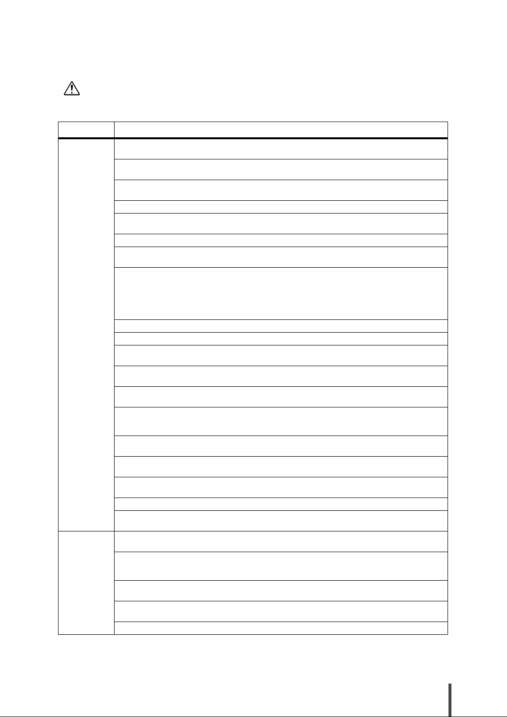
WARNING
not used properly.
For your safety and that of others, please follow these guidelines.
Category Warning
This symbol indicates the possibility of serious or fatal injury if the XG2000 is
Danger of
electric shock
or fire
Danger of
breakage and
injury
Never attempt to disassemble, dismantle, upgrade, or recycle the XG2000 by yourself.
Do not place objects on the XG2000, as there is a risk of electric shock, fire, and/or damage.
Do not install the XG2000 where it will be exposed to direct sunlight, close to a heating device, or in an
environment with much dust and high humidity, as there is a risk of electric shock and fire.
For XG2000 models with cooling vents, do not block off the vents as these prevent the internal parts of the
XG2000 from reaching high temperature, and there is a risk of fire.
Do not wrap the running XG2000 with a cloth. Doing so keeps the heat in, and may cause a fire.
Avoid getting any liquids (such as coffee) or pieces of metal (such as paper clips) into the XG2000, as there
is a risk of electric shock and fire. To avoid foreign objects getting into the XG2000, never place objects on it.
Do not put your fingers into the LAN jack, as there is a risk of electric shock.
Do not use the XG2000 with any voltage other than that specified on the device, as there is a risk of electric
shock and fire.
Should the XG2000 start giving off heat, smoke, and/or a strange smell, immediately disconnect the power
plug from the power outlet. To make this easy, the XG2000 should be located close to the power outlet
(wall socket or power strip), and the power outlet must be readily accessible.
After the power is disconnected, contact the vendor's service department immediately. Continued use of
the XG2000 may cause an electric shock and fire.
Note that in this case, the state of data in transmission is not guaranteed.(P.35)
If the power plug or power socket is dirty, clean it with a dry cloth. Continued use may cause a fire.(P.34)
Do not touch the power plug with wet hands, as there is a risk of electric shock.(P.34)
Insert the power plug completely into the power socket.
A partially inserted power plug may cause an electric shock, give off smoke, and/or catch fire.(P.35)
When you remove a power plug from its outlet, be sure to pull the only power plug itself. Pulling on the
power cord itself may expose the cores or break the cord, and cause electric shock or fire.(P.35)
If the XG2000 is to be left unused for any significant period, remove the power plug from the outlet for
safety reasons. Failure to do so may cause a fire or damage.(P.35)
Do not damage or remodel the power cords, as this may cause electric shock or fire.
Do not place any object on, wrap any object with, pull and/or kick the power cords, as there is a risk of electric shock and fire.(P.34)
Never overload a power outlet with multiple devices.
If too many devices are connected, the power socket may overheat and cause a fire.
When you remove a power plug from an outlet, be sure to pull the power plug itself.
A power plug damaged by incorrect removal may cause an electric shock and fire.
Do not use the XG2000 with a damaged power cord, a damaged power plug, and/or a loose socket.
Continued use under these conditions may cause an electric shock and fire.(P.34)
Do not bundle the power cords. Doing so increases the heat density, and may cause a fire.
Unplug the XG2000 during thunder-storms. Continued use under these conditions risks lightning damage
to the XG2000, and may cause a fire.(P.35)
Do not place the XG2000 on its side or stack up multiple XG2000s.
Ignoring this may damage the XG2000 or injure the operator.
Do not install the XG2000 in an unstable place (such as on a slanted surface or a place subjected to vibrations).
Doing so may cause injury or device damage.
Do not place any objects or perform any work on the XG2000.
Ignoring this may damage the XG2000 or injure the operator.
Never leave the plastic bags the XG2000 was packed in around where children can find them, as they may
suck them into their mouths or place them over their heads in fun, with a severe risk of choking and asphyxia.
Do not dispose the XG2000 with other wastes. If burnt, the XG2000 can explode.
For Safe Use of the XG2000 3
Page 6
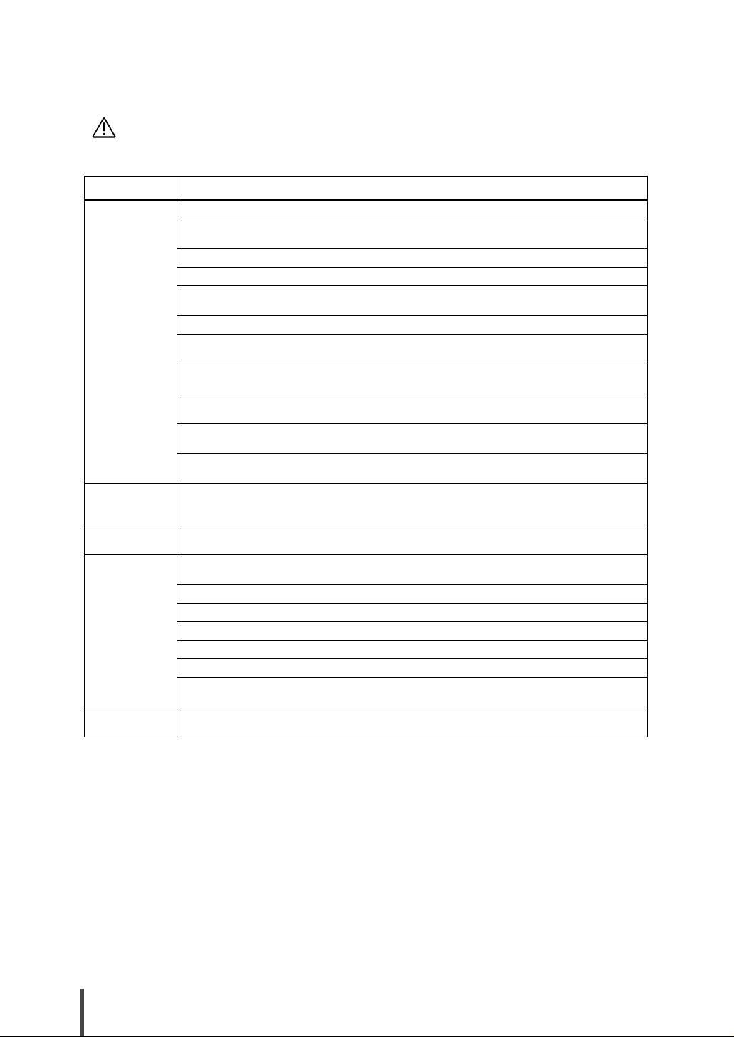
CAUTION
well as damage to the XG2000 and/or to other users and their property, if the
XG2000 is not used properly.
Category Caution
This symbol indicates the possibility of minor or moderate personal injury, as
Danger of device
damage
Danger of
electromagnetic
interference
Danger of
electric shock
Danger when
rackmounting
Danger when
cleaning
Do not place the XG2000 on its side or stack up multiple XG2000s. Doing so may damage the XG2000.
Do not install the XG2000 in an unstable place (such as on a slanted surface or a place subjected to
vibrations). Doing so may damage the XG2000.
Do not place any objects or perform any work on the XG2000. Doing so may damage the XG2000.
Install the XG2000 inside a building. Using the XG2000 outside may damage it.
Do not use the XG2000 in areas of extremely high temperature, low temperature, or a area where the
temperature goes up and down suddenly. Installing the XG2000 in such areas may damage it.
Do not expose the XG2000 to seawater. Installing the XG2000 in such areas may damage it.
Do not use the XG2000 in a place subjected to shock or vibrations. Using the XG2000 in such a place
may damage it.
Do not use the XG2000 in a place where chemicals are being sprayed or may otherwise come in contact
with it. Using the XG2000 in such a place may damage it.
Do not use the XG2000 near objects which generate strong magnetic fields, such as microwave ovens.
Using the XG2000 in such place may damage it.
Do not use the XG2000 with foreign objects (liquids and/or pieces of metal) inside it. Using the XG2000
in such a condition may damage it.
When moving the XG2000, be sure to remove the power plug from the outlet first. No doing so may damage it.
Do not use the XG2000 near a radio or a TV.
Doing so can interfere with the radio and TV reception.
To avoid an electric shock, do not open the cover unless you are a maintenance engineer.
When performing maintenance on the XG2000, be sure to remove the power plug from the outlet first.
Only use the XG2000 if the temperature inside the rack is 40°C or less. Ignoring this may damage the
XG2000.(P.26)
Ensure that the rack is sufficiently ventilated and that excess heat is properly exhausted.(P.26)
Check that the configuration of devices in the rack does not overload the power supply.(P.26)
To ensure the stability of the rack, fix it to the wall or floor as appropriate.(P.26)
Do not install the XG2000 in a rack if it would make it unstable.(P.26)
Check that all units installed in the rack are correctly connected to a grounded power source.(P.26)
When installing and removing the XG2000 from a rack, be sure to hold it by both sides. At least two people should work together.(P.26)(P.30)
When cleaning the XG2000, only use a soft cloth, and wipe it gently.
4 For Safe Use of the XG2000
Page 7
No self maintenance
Never attempt to dismantle or modify the XG2000 yourself. This is extremely dangerous
since the XG2000 includes both high voltage and high temperature components.
If maintenance is required, contact the vendor's service department.
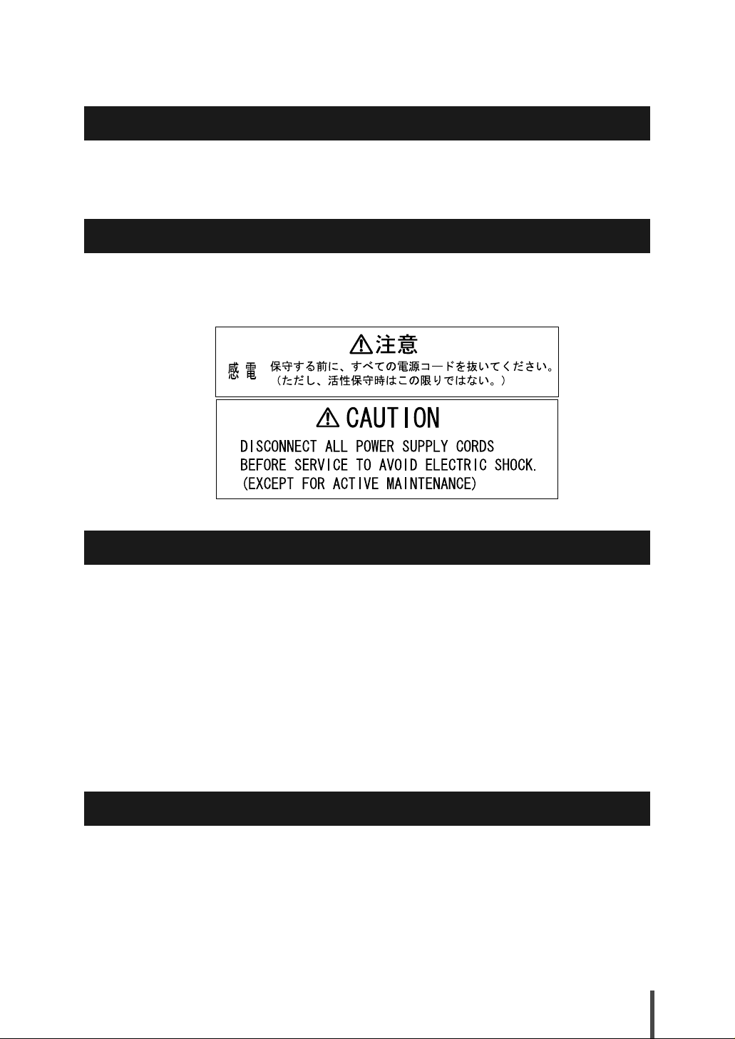
Warning label
The following warning label may be found on the top of XG2000. Do not attempt to remove
this warning label. If you cannot read the details written in the warning label because of dirt or
wear, contact the vendor's service department for a replacement label.
Safety precautions
• The expected life of the XG2000 is approximately five years, assuming use at an ambient
temperature of 25°C.
• Use of this hardware guide, the XG2000, its firmware, and the management software are
the responsibility of the user.
• Fujitsu and its partners accept no responsibility for any errors or data loss arising from use
of the XG2000. Before using the XG2000, it should be understood that the XG2000 is not
guaranteed against failure for any more than the original purchase price.
• Fujitsu and its partners do not approve of any use of the firmware provided with the
XG2000, or of any authorized firmware upgrades, for any purpose other than installation
on the XG2000. Modification and disassemble are not permitted at all.
• When connecting up the fiber optic cables, check that there is no dust, foreign objects or
fingerprints on the connector surfaces.
For security
A default login password is set before the XG2000 is shipped. For security reasons, a new
password should be chosen before the XG2000 is used.
For Safe Use of the XG2000 5
Page 8

Electromagnetic compatibility (USA)
FCC PART 15B (2005) Class A
FCC WARNING:
Changes or modifications not expressly approved by the party responsible for compliance
could void the user’s authority to operate the equipment.
NOTE: This equipment has been tested and found to comply with the limits for a Class A digital device, pursuant to Part 15 of the FCC Rules. These limits are designed to provide reasonable protection against harmful interference when the equipment is operated in a
commercial environment. This equipment generates uses, and can radiate radio frequency
energy and. If not installed and used in accordance with the instrucrtion manual, may cause
harmful interference to radio communications. Operation of this equipment in a residential
area is likely to cause harmful interference in which case the user will be required to correct
the interference at his own expense.
Electromagnetic compatibility (CANADA)
Industry Canada Interference-Causing Equipment Standard ICES-003 Class A.
This Class A digital appartatus compies with Canedian ICES-003.
Cet appareil numérique de la classe A est conforme à la norme NMB-003 du Canada.
Electromagnetic compatibility (EU)
EN55022(2006) Class A
EN61000-3-2(2000)
EN61000-3-3(1995)+A1(2001)
EN55024(1998) + A1(2001) + A2(2003)
Warning
This is a product which meets Class A of EN55022. In a domestic environment this product may
cause raido interference in which case the user may be required to take adequate meausers.
Safety
CAN/CSA C22.2 No. 60950-1, UL60950-1 and EN60950-1
Static electricity
Under certain conditions, twisted pair cables can become charged with static electricity. Connecting a statically charged twisted pair cable to a device can cause the device or its LAN
port to operate falsely or to become damaged.
Use a static removal tool to discharge twisted pair cables to ground immediately before connecting them to devices.
Note that a discharged twisted pair cable that has been left unconnected for a long time may
become statically charged again.
6 For Safe Use of the XG2000
Page 9

High safety
[Use for the high safety required case]
The XG2000 is designed, developed and manufactured as contemplated for general use,
including without limitation, general office use, personal use, household use, and ordinary
industrial use, but is not designed, developed and manufactured for use in situations with
accompanying fatal risks or dangers that, unless extremely high safety is secured, could lead
directly to death, personal injury, severe physical damage or other loss (hereinafter "High
Safety Required Use"), including without limitation, nuclear reaction control in nuclear facility,
aircraft flight control, air traffic control, mass transport control, medical life support system,
and missile launch control in weapon systems.
Do not use the XG2000 for High Safety Required Use without otherwise ensuring the safety
level required. Fujitsu and its related companies assume no liability whatsoever for damages
arising from use of the XG2000 by the user in high-safety applications, and for any claims or
compensation for damages by the user or a third party.
Laser safety
The XG2000 can install a class 1 laser module (XFP module), and can emit invisible laser
light. Do not look into the 10 Gigabit Ethernet port openings. The following warning applies to
the XG2000’s laser:
• The XG2000 can install XFP modules, which are laser devices.
In the USA, these XFP modules are certified as Class 1 laser products that conform to the
requirements of the Department of Health and Human Services (DHHS) regulation 21 CFR
Subchapter J, and this certification is indicated by a label attached to each XFP module.
Outside the USA, these XFP modules are certified as Class 1 laser products that conform
to the requirements given in IEC825-1 (1993) and Amendment11 (1996) of EN60825-1
(1994).
• Even when cables are not connected, invisible laser light may be still emitted from the
port openings. To avoid this laser light, never peer into the port openings.
* XFP module which install in XG2000 must be selected from our specified. (refer to the
specified module list)
For Safe Use of the XG2000 7
Page 10

About This Manual
This section explains who this manual is aimed at, describes the layout of the manual, and gives a
description of the symbols used in this manual.
Targeted reader and expected knowledge
This manual is written for an administrator who has responsibility for network system configuration, maintenance, and management.
Understanding the following knowledge is expected.
• Basic knowledge of networks, intranets and the internet.
• Basic knowledge of system management.
• Basic knowledge of system security.
This manual does not give any explanation of network protocol terms.
Organization
This manual is organized as follows.
Chapter 1 Installation
This chapter lists the items that should be in the XG2000 package, describes the
names and functions of the various components of the XG2000.
Chapter 2 Installation and Operation
This chapter explains how to install, connect, and start the XG2000.
Chapter 3 Troubleshooting
This chapter describes what you should do when your XG2000 has problems.
Appendix
This appendix explains the specifications of the XG2000, and should be referred to
as necessary.
Related manuals
The following manuals are related to this manual. Consult them as required.
• XG2000 Hardware Guide (this manual)
This manual describes the hardware of the XG2000.
• XG2000 User's Guide
This manual describes a variety of operations and procedures, including the installation
and maintenance of the XG2000.
When referring to the "XG2000 User’s Guide", the manual name is usually abbreviated as
"User's Guide".
The user's guide is an online manual, contained in the "XG2000 User's Guide CD-ROM".
8 About This Manual
Page 11
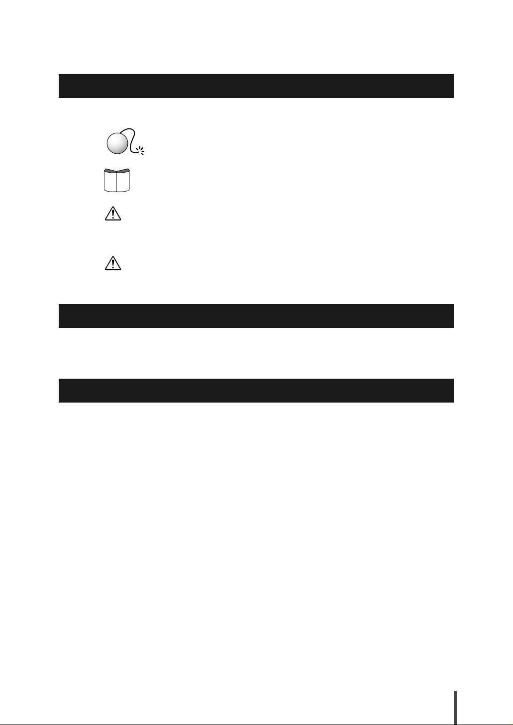
Symbols used in this manual
This manual uses the following symbols.
This symbol indicates a point that operator should pay attention to.
AttentionAttention
This symbol indicates a section which describes related informa-
ReferRefer
tion.
WARNING
CAUTION
This symbol means "Danger! You are in a situation that could
result in bodily injury". Before continuing, make yourself aware of
the hazards involved and become familiar with common ways of
preventing accidents.
This symbol means "Be careful, or you might do something that
could damage your equipment or result in loss of data".
Trademarks and abbreviations used in this manual
Company names and products names referred in this manual are registered trademarks or
trademarks of respective companies.
The trademark ™ and ® have been omitted from this manual.
Product Information
The latest product information including technical information, update information, are available from the following web site:
http://www.pfu.fujitsu.com/products/xg
About This Manual 9
Page 12

10 About This Manual
Page 13

Contents
Preface .........................................................................................................1
For Safe Use of the XG2000 ........................................................................2
Warning notations .............................................................................................. 2
No self maintenance .......................................................................................... 5
Warning label .....................................................................................................5
Safety precautions ............................................................................................. 5
For security ........................................................................................................ 5
Electromagnetic compatibility (USA) .................................................................. 6
Electromagnetic compatibility (CANADA) .......................................................... 6
Electromagnetic compatibility (EU) .................................................................... 6
Safety .................................................................................................................6
Static electricity ..................................................................................................6
High safety ......................................................................................................... 7
Laser safety ....................................................................................................... 7
About This Manual ........................................................................................ 8
Targeted reader and expected knowledge ........................................................ 8
Organization ....................................................................................................... 8
Related manuals ................................................................................................8
Symbols used in this manual ............................................................................. 9
Trademarks and abbreviations used in this manual .......................................... 9
Product Information ............................................................................................9
1
2
3
A
A
Chapter 1 Installation ...................................................................... 13
1-1 Parts List .....................................................................................................14
1-2 XG2000 Components .................................................................................16
1-3 Labels ......................................................................................................... 19
Chapter 2 Installation and Operation ............................................ 23
2-1 Installation Overview ..................................................................................24
2-2 Installation Procedure .................................................................................25
2-2-1 Installation requirements ............................................................................ 25
2-2-2 Installing the XG2000 in a rack ..................................................................26
2-2-3 Uninstalling the XG2000 from a rack ..........................................................30
2-3 Installation of XFP modules ........................................................................31
2-3-1 Installing the XFP modules ......................................................................... 31
2-3-2 Uninstalling the XFP modules ....................................................................32
2-4 Cable Connection .......................................................................................33
2-4-1 Connecting the fiber optic cables ............................................................... 33
2-4-2 Connecting the power cords ....................................................................... 34
2-5 Basic Operation ..........................................................................................35
2-5-1 Turning the XG2000 on ..............................................................................35
2-5-2 Turning the XG2000 off ..............................................................................35
Contents 11
Page 14

Chapter 3 Troubleshooting ............................................................ 37
3-1 Start-up Problems .......................................................................................38
3-2 Hardware Problems ....................................................................................39
Appendix............................................................................................. 41
Appendix-A Specifications ...................................................................................42
A.1 Product Specifications ................................................................................42
A.2 Installation Specifications ........................................................................... 42
12 Contents
Page 15

Installation
This chapter lists the items that should be in the XG2000 package, describes the names
and functions of the various components of the XG2000.
1
1-1 Parts List.................................................................................................14
1-2 XG2000 Components .............................................................................16
1-3 Labels .....................................................................................................19
Page 16

1-1 Parts List
Before proceeding, check that all of the following parts were included in your XG2000 package.
Contact the vendor's service department if any parts are missing and/or the manual has any missing or wrongly collated pages.
Keep the hardware guide (this manual) and the CD-ROM in a safe place.
XG2000
Power code × 2
Rack Mounting Brackets × 2
Rail R Rail L
Serial Cross Cable
Rack Mounting Bracket B × 2
CD-ROM
Hardware Guide
(this manual)
• XG2000 The XG2000 itself.
• CD-ROM Contains documents necessary to operate the XG2000.
• Power Cord A 3-pin cable to connect the XG2000 to a power supply.
• Serial Cross Cable A cable to connect the XG2000 to a PC when the settings need
• Hardware Guide A manual describing the XG2000 hardware and related mat-
14 Installation
Rack Nuts
× 8
Cage Nuts
× 8
Rack Screws (Small)
to be adjusted.
ters (this manual).
× 14
Rack Screws (Large)
× 8
Page 17

• Rack Mounting Brackets Brackets for mounting the XG2000 in a rack. Attach each rack
mounting bracket to the right and left sides of the XG2000, and
fasten to the rack posts with the rack screws (large).
• Rack Mounting Bracket B
A bracket for mounting the XG2000 in a rack. Attach the rack
mounting bracket B to the back-right and back-left sides of the
XG2000, and fasten to the rail (attached to the back-right rack
post) with the rack screws (small).
• Rail R A rail that are attached to the back-right rack post and into
which the back rack mounting bracked are slid and fastened
when mounting the XG2000 in a rack.
• Rail L A rail that are attached to the back-left rack post and into which
the back rack mounting bracked are slid and fastened when
mounting the XG2000 in a rack.
• Rack Nuts When the rack post holes are round, use the rack nuts to fas-
ten the XG2000 and the rails to the rack posts with the rack
screws (large).
• Cage Nuts When the rack post holes are square, use the rack nuts to fas-
ten the XG2000 and the rails to the rack posts with the rack
screws (large).
• Rack Screws (Small) Flat-head screws for fixing the rack mounting brackets and
rack mounting bracket B to the XG2000, and fixing the rack
mounting bracket B to the rails.
• Rack Screws (Large) Pan-head screws for fixing the XG2000 and the rails to the
rack posts.
1
Parts List 15
Page 18

1-2 XG2000 Components
This section explains the names and functions of the various XG2000 components, including the
various indicator LEDs.
XG2000 front
The following explains the names and functions of the components at the front of the
XG2000.
Port 1 - 20
upper stand : odd number
lower stand : even number
• Ports 1-20 XFP modules which connect to the IEEE802.3 ae/ak compliant
• Link/Act LEDs (Green) Displays the condition of respective port.
• Dump Switch Used to collect maintenance information.
• Mng-LAN Used when performing maintenance or adjusting the settings
- Mng - LAN Speed LED (Orange) Lights if the link is 100BASE-TX.
- Mng - LAN Link LED (Green) Lights when the link is established.
• Serial Port Used when performing maintenance or adjusting the settings
•
Status LED (Green) Lights when the XG2000 is in an operable state.
• Alarm LED (Orange) Lights when there is a problem with the XG2000.
•
Power LED (Green) Lights when the XG2000 is receiving power.
Link/Act LED
Link/Act LED
10 Gigabit network served by the XG2000. Connection method
varies depending on which XFP modules are installed.
Each LED lights when a link is established on its port.
The link is established about few seconds after the received
signal is detected.
(LAN connection).
(Console connection).
Mng-LAN Speed LED
Mng-LAN Link LED
Serial Port
Dump Switch
Mng-LAN
Status LED (Status)
Alarm LED (Alarm)
Power LED (Power)
16 Installation
Page 19

XG2000 rear
The following explains the names and functions of the components at the rear of the XG2000.
Power Supply Unit Power Supply UnitRear Fan Unit Rear Fan Unit
1
Rear Fan LED Rear Fan LED
• Rear Fan Unit Exhaust fan.
- Rear Fan LED (Green/Orange) Green LED lights when the Rear Fan Units is in nor-
• Power Supply Unit Supplies power to the XG2000 (includes an exhaust fan).
- Power Supply LED (Green/Orange)
AttentionAttention
In order to avoid a negative effect on the cooling of the XG2000, the Rear Fan Unit
screws should be kept tight at all times.
Power Inlet Power Inlet
Power Supply LED Power Supply LED
mal operation.
Orange LED when there is a problem with the Rear
Fan Unit.
Green LED lights when the XG2000 is on.
Orange LED lights when there is a problem with the
Power Supply Unit.
XG2000 Components 17
Page 20

Display LEDs
There are three main indicator LEDs on the front of the XG2000: Power LED, Alarm LED, and
Status LED. The following explains the LED display under various conditions.
XG2000 Condition
Power Alarm Status
Off Off Off Off
Starting up Power just turned on On Off Off
System starting up On Off *1 Blinking
System start-up completed On Off *1 On
Operable On Off *1 On
After shutdown Off On Off
*1: If the XG2000 is operating normally.
LED
If a problem occurs, the front panel LEDs and the LEDs on the individual parts can be used to
identify the trouble:
XG2000 Condition
Problem
detected
*2: Only detectable and indicated when two power supply units are installed and connected to separate,
*3: Condition of the Alarm LED will depend on the state of the system.
*4: Condition of the Status LED will depend on the state of the system.
Startup error On ---*3 Blinking ---
Rear fan error On On ---*4 Rear Fan LED: Orange
Power fan error On On ---*4 Power Supply LED: Orange
No AC supply *2 On On ---*4 Power Supply LED: Orange
Power supply error On On ---*4 Power Supply LED: Orange
Voltage error On On ---*4 ---
Temperature error On On ---*4 ---
System dump in
progress
independent power supplies.
Power Alarm Status LED on failed part
On On ---*4 ---
LED
Note that the XG2000 will shut itself off when the Temperature error is detected.
Any problems other than those that occur during start up are recorded in the event log. For
details of the event log, refer to the "XG2000 User’s Guide".
18 Installation
Page 21

1-3 Labels
A warning sticker, FCC Label, FCC Canada Label, CSA/CE Label, product nameplate, product ID
label, and MAC label are to be found in various places on the XG2000.
MAC Label
Product ID Label
Product ID Label
MAC Label
1
CSA/CE Label
FCC Canada Label
FCC Label
Warning Sticker
Product Nameplate
Top view of XG2000
Product Nameplate
Right view of XG2000
Warning sticker
Obey the following warning:
Labels 19
Page 22

FCC Label
This indicates statement of Part 15 fo FCC rules.
FCC Canada Label
This indicates notification of CSA.
CSA/CE Label
This indicates CE Marking.
20 Installation
Page 23

Product nameplate
This indicates the model, part number, serial number, etc.
Model
Part Number
Serial Number
MODEL.
PART NO. PA
SER NO. P
1 50/60Hz **** Kg
100-240V
*** **** A/INPUT
******
*****
******
PFU Limited
a Fujitsu company
Product ID Label
This indicates the model and serial number.
MODEL *****
SER. NO *********
MAC Label
This indicates the MAC address:
Model
Serial Number
Rev.
0 1 2 3 4 5 6 7 8 9
Label
0 1 2 3 4 5 6 7 8 9
0 1 2 3 4 5 6 7 8 9
MADE IN JAPAN
1
MAC addresses are allotted relative to the address on the MAC label:
Address on the MAC label Location
xx:xx:xx:xx:xx:xx
xx:xx:xx:xx:xx:xx+1
xx:xx:xx:xx:xx:xx+2
xx:xx:xx:xx:xx:xx+3
xx:xx:xx:xx:xx:xx+4
xx:xx:xx:xx:xx:xx+5
xx:xx:xx:xx:xx:xx+6
xx:xx:xx:xx:xx:xx+7
xx:xx:xx:xx:xx:xx+8
xx:xx:xx:xx:xx:xx+9
xx:xx:xx:xx:xx:xx+10
xx:xx:xx:xx:xx:xx+11
xx:xx:xx:xx:xx:xx+12
xx:xx:xx:xx:xx:xx+13
Mng-LAN
XG2000
Port 1
Port 2
Port3
Port 4
Port 5
Port 6
Port 7
Port 8
Port 9
Port 10
Port 11
Port 12
Labels 21
Page 24

Address on the MAC label Location
xx:xx:xx:xx:xx:xx+14
xx:xx:xx:xx:xx:xx+15
xx:xx:xx:xx:xx:xx+16
xx:xx:xx:xx:xx:xx+17
xx:xx:xx:xx:xx:xx+18
xx:xx:xx:xx:xx:xx+19
xx:xx:xx:xx:xx:xx+20
xx:xx:xx:xx:xx:xx+21
Port 13
Port 14
Port 15
Port 16
Port 17
Port 18
Port 19
Port 20
(=yy:yy:yy:yy:yy:yy)
22 Installation
Page 25

Installation and Operation
This chapter explains how the user should proceed from installation to operation of the
XG2000.
2
2-1 Installation Overview ..............................................................................24
2-2 Installation Procedure.............................................................................25
2-2-1 Installation requirements............................................................25
2-2-2 Installing the XG2000 in a rack..................................................26
2-2-3 Uninstalling the XG2000 from a rack .........................................30
2-3 Installation of XFP modules....................................................................31
2-3-1 Installing the XFP modules ........................................................31
2-3-2 Uninstalling the XFP modules....................................................32
2-4 Cable Connection ...................................................................................33
2-4-1 Connecting the fiber optic cables...............................................33
2-4-2 Connecting the power cords ......................................................34
2-5 Basic Operation ...................................................................................... 35
2-5-1 Turning the XG2000 on .............................................................35
2-5-2 Turning the XG2000 off..............................................................35
Page 26

2-1 Installation Overview
This section reviews the flow of work as the user proceeds from installation to operation of the
XG2000.
Install the XG2000 and the proceed with normal operation as follows:
Check the components
1
"1-1 Parts List"
Check the set up area and install the XG2000
2
"For Safe Use of the XG2000", "2-2 Installation Procedure"
Installation of the XFP modules
3
Install the XFP modules in the XG2000.
"2-3-1 Installing the XFP modules"
Connect the cables to the XG2000
4
Connect the required fiber optic cables and power cords to the XG2000.
"2-4 Cable Connection"
Check that the everything is secure
5
Check that the XG2000 doesn’t wobble and that no cables are loose.
Turn the power on
6
Check that the system starts up normally.
"2-5-1 Turning the XG2000 on"
24 Installation and Operation
Page 27

2-2 Installation Procedure
This chapter describes the installation requirements and installation procedure.
2-2-1 Installation requirements
Before installing the XG2000, read " For Safe Use of the XG2000 (P.2)" and comply with the
installation requirements described below.
Space requirements
When installing the XG2000, a certain amount of installation space is necessary.
When installing the rack, the indicated space (800mm of both the front and rear of the rack)
should be reserved as a service area.
The following figures indicate examples of a 540mm (W) × 850mm (D) 19-inch rack and a
700mm (W) × 950mm (D) 19 inch rack.
When installing in any other 19-inch rack, refer to the user guide provided with the rack.
[540mm (W) X 850mm (D) 19-inch rack]
(Unit: mm)
2
Front
[700mm (W) X 950mm (D) 19-inch rack]
(Unit: mm)
Front
Service area
(Front)
800 850
Service area
(Front)
800 950
CAUTION
The XG2000 may be installed in any rack with an internal depth of between 640mm
and 750mm.
Rack
(Top)
Rack
(Top)
Service area
(Rear)
800
Service area
(Rear)
800
540
700
Installation Procedure 25
Page 28

Set up requirements
Only use the XG2000 under the temperature, humidity and other environmental conditions
specified in "A.2 Installation Specifications (P.42)". Using the XG2000 outside the following
ranges can shorten the lifetime or cause the failure of the XG2000.
• Temperature (5 - 40°C)
• Humidity (20 - 80%RH)
When installing the XG2000 in a rack, note the following.
• Certain types of racks cannot be used. To check whether the XG2000 can be installed in
a given rack, contact the vendor's service department.
CAUTION
• Remember that when an installed unit is operating, the temperature inside the rack
will be higher than the external ambient temperature, particularly if the rack contains multiple units. The rack's internal ambient temperature should not be allowed
to exceed the maximum ambient temperature specified for each installed unit. The
maximum ambient temperature allowed for the XG2000 is 40°C.
• A certain amount of air is required for the XG2000 to operate safely. Make sure
that adequate ventilation is provided and that the front and rear air vents are not
obstructed.
• Be careful that the rack is able to supply sufficient power for all the installed units.
To avoid overloading the rack, check the power requirements specified for the
each installed unit. The power requirement of the XG2000 is 0.22KVA.
• Installing the XG2000 in a rack may cause the entire rack to become unstable. To
avoid this, fix the rack to the wall or floor as appropriate.
• Check that all the installed units are correctly grounded. Special care should be
taken if the unit's power supply is not drawn directly from the distribution board
(such as when a power strip is used, for example). When multiple devices are connected to a single power strip, the combined leakage currents can overwhelm the
grounding capacity of the power strip.
• Set the XG2000 nearby the AC outlet, and keep it within the reach of the power
cord for pulling it easily. The XG2000 is shut off by pulling the power cord off the
AC outlet.
2-2-2 Installing the XG2000 in a rack
The following explains how to install the XG2000 in a 19-inch rack.
1. Take the XG2000 out of its box.
26 Installation and Operation
Page 29

2. Fix the nuts and rails to the rack posts.
First, choose nuts, cage nuts or rack nuts, by the type of hole dug in the rack post.
When the rack has square post holes, cage nuts are used. When round holes, rack nuts are
used.
[When the rack has square post holes]
Rack Post
Rack Post
Refer to Detail A
Cage Nuts
Front
Cage Nuts
Rack Post
Cage Nuts
[When the rack has round post holes (top of view)]
Rack Screws (Large)
Rail L
Rail R
Rack Post
Rack Post
Cage Nuts
Spring lugs at the top and bottom
Detail A
Rack Screws
(Large)
2
Rack Post
Cage Nut
Detail B
Front
Rack Post
Refer to Detail B
Refer to Detail C
<<Top of View>>
Rail L
Cage Nut
Detail C
Rack Screw
(Large)
Installation Procedure 27
Page 30

[When the rack has round post holes]
Rack Post
Rack Screws (Large)
Rack Post
Rack Nuts
Front
Rack Nuts
Rack Nuts
Rail L
Refer to Detail A
Rack Post
[When the rack has round post holes (top of view)]
Rack Post
Rail L
Rail R
Rack Nuts
Clip the rack nuts onto the
rack post so that the holes
are lined up.
Detail A
Rack Post
Rack Nut
Rack Screws (Large)
Rack Post
Rack Nut
Detail B
28 Installation and Operation
Front
Rack Post
Refer to Detail B
Refer to Detail C
<<Top of View>>
Detail C
Rack Screw (Large)
Page 31

3. Fix the four rack mounting brackets to the XG2000.
Each of the four rack mounting brackets (two of front side, two of back side) has two holes
that should line up with matching holes on the sides of the XG2000, as shown in the diagram.
Attach each rack mounting bracket using the countersunk bracket screws provided.
Rack Screws (Small)
Rack Screws (Small)
Rack Mounting Bracket
Rack Mounting Bracket B
Rack Screws (Small)
Rack Screws (Small)
4. Slide the XG2000 into the rack and fasten it in place.
Two rack mounting bracket of front side is fixed to the rack post with each of two rack screw
(small). and two rack mounting bracket B of reae side is fixed to the rails (rail R and rail L)
with each of three rack screws (small).
Securely tighten all the screws with a screwdriver.
2
Rack Screws (Large)
Rack Screws (Small)
Installation Procedure 29
Page 32

5. This completes the rack installation procedure.
Rack Post Rack Post
2-2-3 Uninstalling the XG2000 from a rack
The following explains how to uninstall the XG2000 from a rack.
1. Undo the rack screws that were used to fasten the XG2000 to the rack.
Rack Screws (Small)
Rack Screws (Large)
2. Slide the XG2000 forward, and remove it from the rack.
30 Installation and Operation
Page 33

2-3 Installation of XFP modules
This section describes the installation of the XFP modules.
2-3-1 Installing the XFP modules
The following explains how to install the XFP modules in the XG2000.
1. Install the XPF module in the XG2000.
How to install the XFP module is the following,
(1) Insert the XFP module with the cable connector facings outward. In cases installing the
XFP module in an odd port number, the slot connector facings down. Otherwise, in cases
installing the XFP module in an even port number, the slot connector facings up.
(2) Slide the XFP module into the slot until it snaps into place without the lever lifting.
2
Label
Installation of XFP modules 31
Page 34

2-3-2 Uninstalling the XFP modules
The following explains how to uninstall the XFP modules from the XG2000.
1. Uninstall the XPF module from the XG2000.
How to uninstall the XFP module is the following,
(1) Remove the XFP module from the slot. In cases removing the XFP module from an odd
port number, lift off the lever horizontally. Otherwise, in cases removing the XFP module
from an even port number, lift up the lever horizontally.
(2) Pull the XFP module out with the lever.
2
Lever
1
1
2
Lever
32 Installation and Operation
Page 35

2-4 Cable Connection
This section explains how to connect the cables and power cords.
2-4-1 Connecting the fiber optic cables
The cables need to be connected to the XG2000 XFP modules.
1. Connect the fiber optic cables to the XG2000.
Connect the fiber optic cables to the XFP modules (Port 1 - Port 20) on the front of XG2000.
Port 1
Port 2
CAUTION
AttentionAttention
Port 3
Port 4
An fiber optic connector is used when connecting two fiber optic cables. When connectors such as these are used, it is important that they be connected correctly.
If a connector is misconnected, or cleaned incorrectly, it can be damaged. If the Fiber
optic connector is dirty or damaged, data transmission may become errorprone and/
or unstable.
• It is necessary that the connectors be fixed in the correct position, in order to
protect the connector interface against external influences.
• Connection quality is influenced by two factors: the type of connector and whether
it is properly cleaned and connected. Optical losses are often caused by dirty fiber
connectors. Always keep your connectors clean and protect them with a dust
power plug or cover if they are not being used.
• Before connecting any cables or connectors, use an lint-free alcohol pad
(included in the cleaning kit) to clean the ferrule, the protective tube, and the end
of the fiber core. If a large light loss is detected, and the cause is not immediately
clear, clean the connector as a first attempt to resolve the problem.
Port 5
Port 6
Port 7
Port 8
Port 9
Port 10
Port 11
Port 12
Port 13
Port 14
Port 15
Port 16
Port 19
Port 17
Port 18
Port 20
2
Cable Connection 33
Page 36

2-4-2 Connecting the power cords
After connecting the peripheral units, connect the XG2000 power cords.
WARNING
• Do not touch the power plug with wet hands, as there is a risk of electric shock.
• Do not damage or remodel the power cords, as this may cause electric shock or
fire. Placing a heavy object on, pulling, excessively bending, twisting, or overheating a power cord can damage it, and may cause electric shock or fire.
• Do not use the XG2000 with a damaged power cord, a damaged power plug, and/
or a loose socket. Continued use under these conditions may cause a fire.
• If the power plug pins or socket holes are dusty, clean with a dry cloth. Continued
use with a dirty power plug or socket may cause electric shock or fire.
1. Connect the power cords to the XG2000.
Insert the plug at the end of the power cord into the power inlet at the rear of the XG2000.
34 Installation and Operation
Page 37

2-5 Basic Operation
This section explains the basic operation of XG2000.
2-5-1 Turning the XG2000 on
WARNING
• Unplug the XG2000 during thunder-storms. Continued use under these conditions
risks lightning damage to the XG2000, and may cause a fire.
• Insert the power plug completely into the power socket. Using the XG2000 with a
half inserted power plug may cause a fire or damage.
• If the XG2000 is to be left unused for any significant period, remove the power plug
from the outlet for safety reasons. Failure to do so may cause a fire or damage.
CAUTION
Do not move, shock, or vibrate the XG2000 while it is on.
1. Connect the power cord to the power outlet.
Insert the plug at the other end of the power cord into the power strip or wall socket.
The Power LED (Green) on the front of the XG2000 should turn on. The Alarm LED (Orange)
should turn on for a moment, then should turn off. The Status LED (Green) should turn on.
If an error occurs while the XG2000 is starting up, the Alarm LED (Orange) will start blinking.
2
2. When the system has finished starting up, the Status LED (Green) turns on.
2-5-2 Turning the XG2000 off
WARNING
• When you remove a power plug from its outlet, be sure to pull the only power plug
itself. Pulling on the power cord itself may expose the cores or break the cord, and
cause electric shock or fire.
• Should the XG2000 start giving off heat, smoke, and/or a strange smell, immediately disconnect the power plug from the power outlet. To make this easy, the
XG2000 should be located close to the power outlet (wall socket or power strip),
and the power outlet must be readily accessible. After the power is disconnected,
contact the vendor's service department immediately. Continued use of the
XG2000 may cause an electric shock and fire. Note that in this case, the state of
data in transmission is not guaranteed.
1. Execute the "system shutdown" command.
If the firmware has not been updated yet, then execute "system shutdown" from the command line.
For details of the system shutdown dommand, refer to the "Command Reference" section in
ReferRefer
the "XG2000 User's Guide".
2. Disconnect the power cord to the power outlet.
Basic Operation 35
Page 38

36 Installation and Operation
Page 39

Troubleshooting
This chapter describes what you should do when your XG2000 has problems.
3
3-1 Start-up Problems...................................................................................38
3-2 Hardware Problems................................................................................39
Page 40

3-1 Start-up Problems
The following errors may occurs when the XG2000 is started up.
If the cause of the error cannot be resolved, contact the vendor's service department.
The following explains some general errors that can occur. Check if any of these match your problem.
The XG2000 does not turn on
[Symptom] The power code is inserted to the power outlet, but the XG2000 does not power up.
[Cause] Possible causes:
1 Loose cable, or
2 Hardware failure
[Action] Take action in the following with the corresponding number;
1 Check that all cables are connected properly, then (if the XG2000 still doesn't turn on)
or
2 Contact the vendor's service department.
Status LED blinks, but the XG2000 does not start up
[Symptom] The XG2000 has not started within a few minutes of the XG2000 turned on.
The Status LED keeps blinking.
[Cause] Probable hardware failure.
[Action] Contact the vendor's service department.
Alarm LED lights, but the XG2000 does not start up
[Symptom] The XG2000 has not started within a few minutes of the XG2000 turned on.
The Alarm LED (Orange) lights.
[Cause] Probable hardware failure.
[Action] Contact the vendor's service department.
38 Troubleshooting
Page 41

3-2 Hardware Problems
This section explains what should be done when a fan, temperature, Voltage, power supply, or
memory or XFP error occurs. Contact the vendor's service department when the following errors
occurred.
Fan error
When a problem is detected with a fan, the front panel Alarm LED lights up in orange, the
LED of the fan unit in which the error has occurred lights up in orange, and an error is
recorded in the event log. If a fan error occurs, contact the vendor's service department.
Temperature error
When XG2000 overheats, the Alarm LED lights up in orange, and a temperature error is
recorded in the event log. In this case, check that the ambient and internal rack temperatures
are within the specified temperature range, adjust them if they are not and try turning the
XG2000 back on. When error occurs even though the ambient rack temperatures are acceptable, turn the XG2000 off and contact the vendor's service department.
Voltage error
When a voltage problem is detected, the Alarm LED lights up in orange, and an error is
recorded in the event log. In this case, turn the XG2000 off and contact the vendor's service
department.
3
Power supply error
When a power supply problem is detected, the Alarm LED lights up in orange, the power supply LED of the power supply unit in which the error has occurred lights up in orange, and an
error is recorded in the event log. Verify that the AC power supply for the failed power supply
unit is normal and the cable has not come loose.
If some other reason has caused the power supply LED to light up, contact the vendor's service department.
Memory error
Startup diagnostic tests are run after the power is turned. If a memory error is detected at this
stage, the Alarm LED blinks, but an event log entry is not created. If a memory error is
detected during operation, an event log entry is created and the system automatically
reboots. Note that whether or not a memory error results in an event log entry is a matter of
timing.
If memory errors occur repeatedly, contact the vendor's service department.
XFP error
When a problem is detected with a XFP module, an error is recorded in the event log. In addition, if the transceiver in the XFP module overheats, the system shutdown the XFP module.
Hardware Problems 39
Page 42

40 Troubleshooting
Page 43

Appendix
This appendix explains XG2000 specifications.
Appendix-A Specifications ............................................................................42
A.1 Product Specifications ..................................................................42
A.2 Installation Specifications..............................................................42
Page 44

Appendix-A Specifications
This section details the specifications of XG2000.
A.1 Product Specifications
The product specifications of the XG2000 are as follows:
Items Overview
10 Gigabit ports Port1 - Port20 IEEE802.3ae/ak compliant 10 Gigabit Ethernet port × 20
Serial Port RS-232C D-SUB9 × 1
Management LAN Mng-LAN 10BASE-T/100BASE-TX × 1
Indicators LED Power (Green), Alarm (Orange), Status (Green), Rear fan × 2,
A.2 Installation Specifications
The installation specifications of the XG2000 are as follows:
Items Specifications
Dimensions
(Excluding protrusions)
Maximum weight 14kg
Power Cord for 3-pin socket (grounded)
Power source Voltage AC100 (-10%) - 240V (+10%)
Input current 100 - 240 V 2.2 - 1.0 A/Input
Ambient temperature XG2000 on +5 - +40°C (Inlet temperature)
Ambient humidity XG2000 on 20 - 80%RH (Non-condensing)
Temperature gradient XG2000 on 15°C/hr or less (Non-condensing)
Ambient dust 0.15mg/m3 or less
Ambient noise 55dB or less
Electromagnetic compatibility FCC Class A
Service area Front 800mm
Installation 1U in a 19-inch rack
Width 440mm
Depth 480mm
Height 43.8mm
Phase Single-phase
Frequency 50 or 60Hz (+2% / -4%)
XG2000 off 0 - +50°C (Inlet temperature)
XG2000 off 8 - 80%RH (Non-condensing)
XG2000 off
Rear 800mm
(for XFP modules)
Console connection port
Power supply units × 2
CE Marking
42 Appendix
Page 45

XG2000 Hardware Guide
P3N1-E112-02EN
Date of issue: March 2007
Issuing authority: PFU LIMITED
Printed in Japan
• Contents of this manual are not to be reproduced without permission from PFU.
• The contents of this manual may be updated without notice.
• PFU assumes no liability for damages to third party copyrights or other rights
arising from the use of any information in this manual.
• Manuals with missing or wrongly collated pages will be replaced free of charge.
 Loading...