

Fujitsu Waterstage WOYG160LJL, Waterstage WOYK150LJL, Waterstage WSYK170DJ9, Waterstage WOYK170LJL, Waterstage WSYG160DJ6 Installation Manual
Page 1

U0651595_2011_EN_2
10/09/2019
Outdoor unit
WOYG160LJL
WOYK150LJL
WOYK170LJL
Hydraulic unit
WSYG160DJ6
WSYK170DJ9
INSTALLATION
Air to Water Heat Pump Split single service
For professionals. To be kept by the user for future reference
EN
Page 2

■ Installation and maintenance rules
The appliance must be installed and maintained
by an approved professional in accordance with
current regulations and codes of practice.
• Warning, hydraulic unit should not be installed
in an air current.
■ Handling
The outdoor unit must not be placed in a horizontal
position during transport.
If not kept upright during transport, the appliance
could be damaged through displacement of
the refrigerant and damage to the compressor
suspension.
Any damage caused by transportation in a horizontal
position is not covered by the warranty.
If necessary, the outdoor unit may be tilted only
during manual handling (to go through a door or up
a staircase). This operation must be conducted very
carefully and the appliance must be immediately
restored to the upright position.
■ Containment of refrigeration circuits
All refrigeration circuits are sensitive to contamination
from dust and moisture. If such pollutants penetrate
the refrigeration circuit, they can aect the reliability
of the heat pump.
Make sure that the connections and refrigeration
circuits (hydraulic unit, outdoor unit) are
protected correctly.
In the event of a subsequent failure and following
an inspection, the presence of moisture or
foreign bodies in the compressor oil would
automatically void the warranty.
- Check upon receipt that the ttings and refrigeration
circuit caps mounted on hydraulic unit and outdoor
unit are properly seated and secured (cannot be
loosened with bare hands). If this is not the case,
tighten them using a C spanner.
- Check also that the refrigeration connections are
sealed (plastic caps or tubes crimped at the ends
and brazed). If the caps must be removed during
the installation (tubes to be re-cut for example),
put them back as soon as possible.
■ Hydraulic connections
The connection must comply with industry standard
practice according to current regulations.
Remember: Seal everything when tting in
accordance with industry standard practice for
plumbing work:
- Use suitable seals (bre gasket, O-ring).
- Use Teon or hemp tape.
- Use sealing paste (synthetic depending on the
case).
Use glycol/water mix if the minimum ow
temperature is set below 10°C. If you are using a
glycol/water mix, arrange for an annual check on the
quality of the glycol. Use monopropylene glycol only.
The recommended concentration is 30% minimum.
Never use monoethylene glycol.
• In some installations, the presence of dierent
metals can cause corrosion problems; the
formation of metal particles and sludge can
appear in the hydraulic circuit.
• In this case, it is advisable to use a corrosion
inhibitor in the proportions indicated by the
manufacturer.
• You must also ensure that treated water does
not become corrosive.
Page 3
■ Electrical connections
2
1
3
• Before any maintenance operation, ensure
that the general power supply is switched o.
• Specications of electricity supply
The electrical installation must be carried out in
accordance with prevailing rules.
Electrical connections will only be made once all
other installation operations (fastening, assembly,
etc.) have been completed.
Warning!
The contract signed with the energy provider must
be sucient not only to cover the heat pump's power
requirements but also the combined sum of all the
appliances likely to be operating at the same time. If
the power is too low, check the power rating stated
in your contract with your energy provider.
Never use a power socket for the power supply.
The heat pump must be supplied directly with power
(without external switch) by special protected leads
from the electric panel via dedicated bipolar circuit
breakers, C curve for the outdoor unit, C curve for
the electrical heating and domestic water backups
(see tables page 35).
The electrical installation must be tted with a 30mA
RCD.
This appliance is designed to operate using a
nominal voltage of 230 V or 400 V, +/- 10%, 50 Hz
(depending on model).
• General remarks on electrical connections
It is essential to maintain neutral-phase polarity
when making electrical connections.
Rigid wires are preferable for xed installations,
particularly in a building.
Tighten the cables using the cable glands to prevent
the feed wires from being accidentally disconnected.
The earth connection and its continuity must be
ensured.
• Cable glands
To ensure the stability of power (Low Voltage) and
sensor (Extra-Low Voltage) cables, it is essential
that the cable glands are tightened according to the
following recommendations:
Size of cable
gland (PE)
(mm)
PG7 1 to 5 1.3 1
PG9 1.5 to 6 3.3 2.6
PG16 5 to 12 4.3 2.6
Diameter of
cable
(mm)
Cable gland
tightening
torque
(check-nut)
(N.m)
Coupling net
tightening
torque
(N.m)
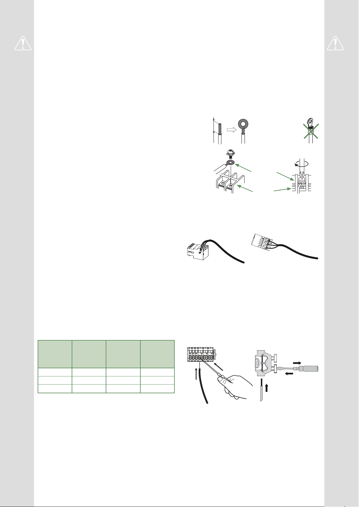
• Connecting to screw terminals
The use of ring, spade or blade terminals or
caps is prohibited.
- Always select wire that complies with current
standards.
- Bare the end of the wire to around 25 mm.
- With round end pliers, form a loop with a diameter
which matches the tightening screws on the
terminal.
- Tighten the terminal screw rmly onto the
loop created. Insucient tightening can cause
overheating, leading to breakdown or even re.
Rigid wires
25 mm
Loop
Lug on
exible wires
prohibited
Screw and special
washer
Terminal
• Connecting to controller boards
- Remove the corresponding connector and make
the connection.
Pre-cabled bundle connector and/or screw connector
• Connecting to spring terminals
- Bare the end of the wire to around 12 mm.
- Push the spring with a screwdriver so that the wire
enters the cage.
- Slide the wire into the opening provided for this
purpose.
- Remove the screwdriver and then check that the
wire stays gripped by the cage by pulling on it.
Page 4

This appliance must be installed by qualied personnel holding a certicate of competence in the
handling of refrigerants.
Contents
Description of the equipment 6
Packing .................................6
Unpacking and supplies ....................6
Denitions ...............................6
Optional equipment ........................6
Operating Range ..........................6
General characteristics .....................7
Description .............................12
Operating principle .......................14
Installation 16
Installation of refrigeration connections ........16 Installation of the outdoor unit ...............18
Installation of the hydraulic unit ..............20
Refrigeration connections 22
Rules and precautions .....................22
Shaping the refrigeration pipes ..............22
Checks and connection ....................25
Filling the installation with gas ...............26
Hydraulic connections 30
Connecting the hydraulic unit to the heating circuit ..30
Filling and bleeding the installation ...........31
Heating circulation pump speed settings .......32
Electrical connections 34
Cable dimensions and protection rating .......35
Outside sensor ..........................42
Electrical connections on the outdoor unit side ..36
Electrical connections on the hydraulic unit side ..38
Room sensor (optional) ....................42
Commissioning 44
Controller Interface 46
User Interface ...........................46
Display Description .......................47
Installer Menu ...........................48
- 4 -
Navigating the Menus .....................48
Modifying Settings ........................49
Temperature control ......................50
Waterstage / Installation / 2011 - EN
Page 5

Controller Menu 52
Menu Structure ..........................52
Installed options .........................53
Hydraulic conguration ....................53
Heat Pump Conguration ..................58
System status ...........................60
Auxiliary functions ........................62
Settings ................................64
Easy Start ..............................68
Basic Hydraulic Layout 70
Electrical Cabling Plans 72
Fault Diagnosis 76
Faults in the Hydraulic Unit .................76 Faults in the Outdoor Unit ..................77
Maintenance of the installation 78
Hydraulic checks .........................78
Checking the outdoor unit ..................78
Electrical checks .........................78
Other maintenance 79
Emptying the hydraulic unit .................79 Distribution valve .........................79
Quick-start procedure 80
Start-up check-list ........................80 Commissioning technical datasheet ..........82
Instructions for the end user 83
Waterstage / Installation / 2011 - EN
- 5 -
Page 6

Description of the equipment
Packing
►
• 1 package : Outdoor unit.
• 1 package : Hydraulic unit and outside temperature
sensor.
Unpacking and supplies
►
While the courier is still present, carefully check the
general appearance of the appliances and check
that the outdoor unit has not been laid in a horizontal
position.
In the event of a dispute, send any relevant reservations
to the carrier in writing within 48 hours and send a copy
of the letter to Customer Services.
Packing contents list
Heat Pump Outdoor unit Hydraulic unit
Model Reference Code
Waterstage SHP 16 WOYG160LJL WSYG160DJ6
Waterstage SHP TRI 15 WOYK150LJL
Waterstage SHP TRI 17 WOYK170LJL
Denitions
►
- Split: The heat pump consists of two elements
(an outdoor unit to be installed outdoors and a hydraulic
unit to be installed inside the dwelling).
- Air/water: The surrounding air is the energy source.
This energy is transmitted to the heating circuit water
by the heat pump.
- Inverter: The fan and compressor speeds are
modulated according to the heating requirements.
This technology enables you to save on energy and
operate on a single-phase power supply, whatever
the heat pump's output, by avoiding pulling signicant
amounts of current at start-up.
- COP (Coecient of Performance): This is the
relationship between the energy transmitted to the
heating circuit and consumed electrical energy.
WSYK170DJ9
Optional equipment
►
• Dual circuit kit (code UTW-KZSXJ)
for connecting 2 heating circuits.
• Regulation extension kit (code UTW-KREXD)
to manage a 2nd heating circuit, swimming pool,
telephone modem etc...
• DHW kit (code UTW-KDWXD)
for connecting a mixed DHW tank
(with built-in electrical backups).
• Boiler connection kit (code UTW-KBSXJ)
for connecting a boiler to the heat pump.
• Room thermostat (code UTW-C55XA),
Wireless room thermostat (code UTW-C58XD)
for correcting the ambient temperature.
• Remote control (code UTW-C74TXF or UTW-C74HXF),
Wireless remote control (code UTW-C78XD)
for correcting the ambient temperature and
programming the heat pump.
• Cooling kit (code UTW-KCLXD).
• High ow rate circulation pump kit (code UTW-PHFXG)
for the installation of 1 underoor heating circuit.
Operating Range
►
This heat pump provides:
- Heating in winter,
- The management of electrical backups, for extra
heating on the coldest days,
or
- Installation with boiler connection* for extra heating on
the coldest days,
- Management of two heating circuits*,
- Production of domestic hot water* (provided that it is
combined with a mixed DHW tank),
- Cooling in summer* (for underoor heating-cooling
system or fan-convectors).
*: These options require the use of additional kits
(see chapter "Required accessory" or "Optional equipment").
- 6 -
Waterstage / Installation / 2011 - EN
Page 7

General characteristics
►
Model name Waterstage SHP 16 TRI 15 TRI 17
Rated heating performances (outdoor temp. / ow temp.)
Heat output
+7°C/+35°C - Underoor heating system kW 16.00 15.00 17.00
-7°C/+35°C - Underoor heating system kW 14.50 13.20 15.00
+7°C/+55°C - Radiator kW 14.50 13.20 15.00
-7°C/+55°C - Radiator kW 10.90 13.20 14.20
Power consumption
+7°C/+35°C - Underoor heating system kW 3.86 3.46 4.10
-7°C/+35°C - Underoor heating system kW 5.27 4.55 5.32
+7°C/+55°C - Radiator kW 5.58 4.77 5.49
-7°C/+55°C - Radiator kW 5.89 6.77 7.40
Coecient of performance (COP) (+7°C/+35°C) 4.15 4.33 4.15
Electrical specications
Electrical voltage (50 HZ) V 230 400 400
Maximum current for appliance A 28 14 14
Nominal current A 17.2 6.43 7.4
Maximum current of the Heating system electrical backup A 26.1 39 39
Power of the Heating system electrical backup kW
6 kW
(single phase)
9 kW
(3-phase)
9 kW
(3-phase)
Circulation pump actual power consumption W 39.5 39.5 39.5
Maximum power consumed by the outdoor unit W 6300 6770 7400
Hydraulic Circuit
Maximum operating pressure MPa (bar) 0.3 (3) 0.3 (3) 0.3 (3)
Available heating pressure at nominal point +7°C / +55°C (Δt8) MPa (bar) 0.05 (0.5) 0.055 (0.55) 0.045 (0.45)
Minimum allowed hydraulic ow rate l/h 600 600 600
Miscellaneous
Weight of outdoor unit Kg 137 138 138
Noise level at 5 m 1 (Outdoor unit) dB (A) 45 45 45
Sound power level in accordance with EN 12102 2 (Outdoor unit) dB (A) 67 67 67
Weight of hydraulic unit (empty / full of water) Kg 53 / 75 53 / 75 53 / 75
Hydraulic unit water capacity l 30 30 30
Noise level at 1 m 1 (Hydraulic unit) dB (A) 37 37 37
Sound power level in accordance with EN 12102 2 (Hydraulic unit) dB (A) 45 45 45
Heating system operating limits
Outdoor temperature min/max °C -25 / +35 -25 / +35 -25 / +35
Max. heating water ow temperature underoor heating °C 45 45 45
Max. heating water ow temperature low temperature radiator °C 60 60 60
Min. ow water temperature °C 8 8 8
Refrigeration circuit
Gas pipe diameters Inches 5/8 5/8 5/8
Liquid Piping Diameters Inches 3/8 3/8 3/8
Factory ll of refrigerant R410A 3 g 3800 3800 3800
Maximum operating pressure MPa (bar) 4.15 (41.5) 4.15 (41.5) 4.15 (41.5)
Minimum / Maximum length of pipes
Maximum length of pipes
5
Maximum level dierence
(Outdoor unit over hydraulic unit and heating only / Other cases)
4 / 6
m 5 / 15 5 / 15 5 / 15
m 30 30 30
m 25 / 15 25 / 15 25 / 15
1
Sound pressure level at (x) m from the appliance, 1.5m off the ground, open eld
directionality 2.
2
The sound power level is a laboratory measurement of the emitted sound power. It
does not correspond to a measurement of the perceived sound power.
Waterstage / Installation / 2011 - EN
3
Refrigerant R410A as per NF EN 378.1 standard.
4
Filling with refrigerant R410A is done at the factory.
5
Taking into account a possible additional ll of refrigerant R410A (see "Additional
lling", page 28).
6
The announced thermal and acoustic performances are measured with 7.5m length
refrigerant lines.
- 7 -
Page 8
■ Waterstage SHP 16
■ Waterstage SHP TRI 15
Waterstage SHP TRI 17
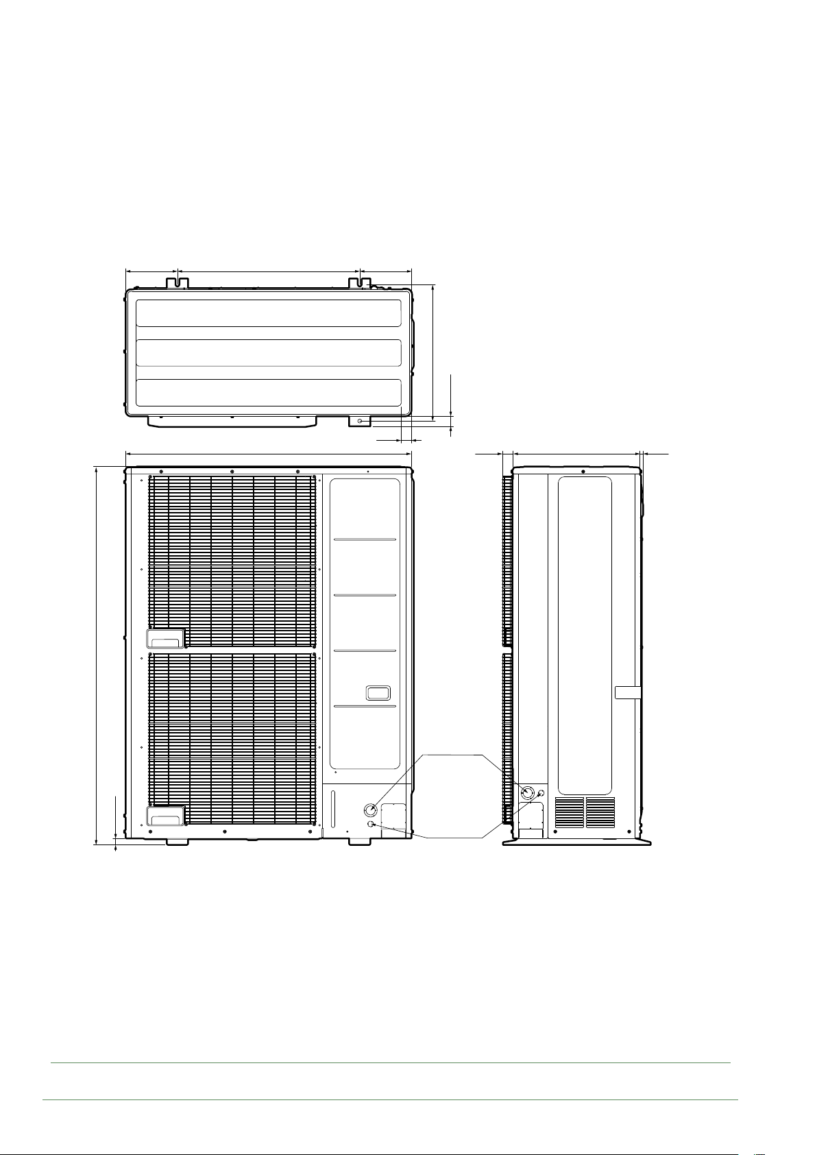
196 196
688
40
1080
515.5
37.7
39.3
480
12.1
1428
23.6
Ø50
Ø34.5
Ø22.2
g. 1 - Dimensions of outdoor units (in mm)
- 8 -
Waterstage / Installation / 2011 - EN
Page 9
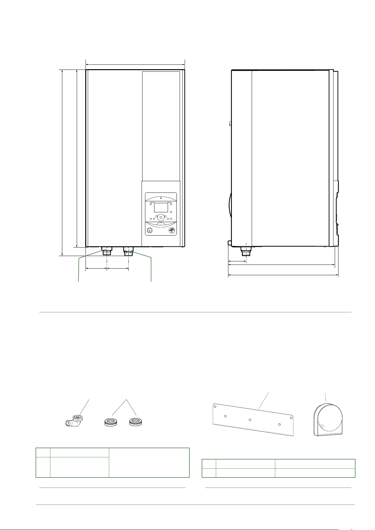
3**
4
8
7
■ Hydraulic unit
805
847
450
9897
Heating return
ø M 26x34
Space requirements of the hydraulic unit, see page 20.
g. 2 - Dimensions of hydraulic unit (in mm)
1*
Heating ow
ø M 26x34
2*
81
471
493
5 6
1 Elbow
Plugs (x9)
2
(depending on
model)
g. 3 - Accessories provided with the outdoor unit
Waterstage / Installation / 2011 - EN
for condensate evacuation.
5 Bracket for attaching hydraulic unit.
6 Outside sensor to monitor the outdoor temp.
g. 4 - Accessories provided with the hydraulic unit
- 9 -
Page 10

0102030405060708090 100
Variable pressure Constant pressure
mCE
8
7
6
5
4
3
2
1
0
0 0,5 1 1,5 2
1
55
3
1 mbar=10 mmCE=100 Pa
88
77
1
mCE
8
7
6
5
4
3
2
1
3
3
/h
1,5 20,50
m
m/h
0
0 0,5 1 1,5 2
g. 5 - Available hydraulic pressures and ow rates
Outside sensor QAC34
32500
30000
27500
43907
10000
2490
1000
338
-50
-25025 50 75
°C
25000
22500
20000
17500
15000
12500
10000
7500
5000
2500
0
88
77
3
1
HP return sensor
HP ow sensor
1 mbar=10 mmCE=100 Pa
55
1
3
3
/h
1,5 20,50
m
m/h
°C
g. 6 - Ohmic sensor values (Hydraulic unit)
- 10 -
Waterstage / Installation / 2011 - EN
Page 11
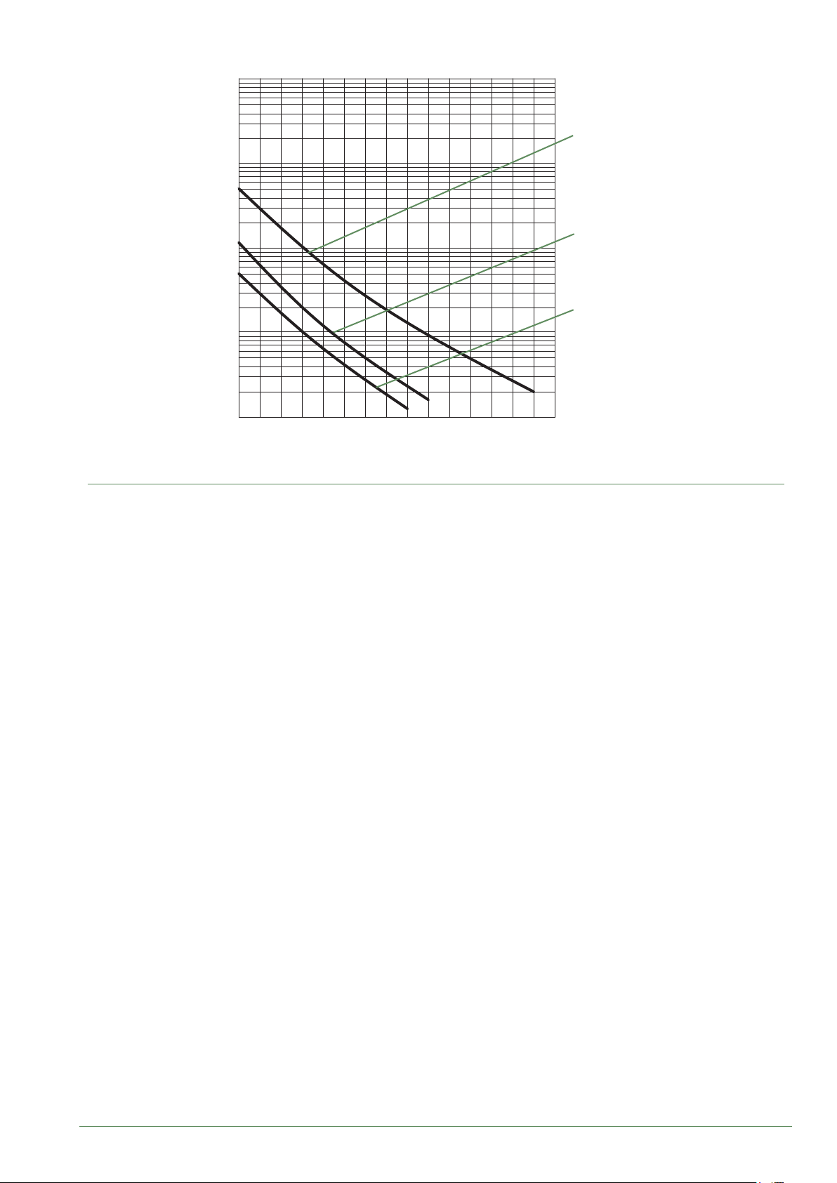
10000
1000
Ohmic value (kΩ)
- Compressor
- Discharge
- Condensation
- Expansion valve
100
10
1
-20 -10 0 10 20 30 40 50 60 70 80 90 100 110 120 130
g. 7 - Ohmic sensor values (Outdoor unit)
- Outdoor unit
- Evaporator inlet
Temperature °C
Waterstage / Installation / 2011 - EN
- 11 -
Page 12

Description
►
■ Waterstage SHP 16
■ Waterstage SHP TRI 15
Waterstage SHP TRI 17
12
8
13
4
1
3
2
5
9
14
1
2
6
7
11
10
Key:
1. High performance and low noise impeller.
2. Electrical motor with variable "Inverter" operation.
3. "Inverter" control unit.
4. Check lights and buttons.
5. Connection terminal blocks
(power supply and interconnection).
6. Refrigerant storage bottle.
7. 4-way valve.
8. Anti-corrosion treated bodywork.
9. Main circuit electronic expansion valve.
10. Noise and thermally insulated "Inverter" compressor with liquid injection port.
11. Refrigeration connection valves (ared connectors) with protective caps.
12. Holding tank with condensate drain hole.
13. High-performance exchange surface evaporator; anti-corrosion treated hydrophilic aluminium ns and
grooved copper tubes.
14. Solenoid valve for liquid injection.
g. 8 - Outdoor unit components
- 12 -
Waterstage / Installation / 2011 - EN
Page 13

■ Hydraulic unit
1
13
15
16
8
14
5
2
67
3 4
8
9
10
11
12
5
Key:
1 - Electric box.
2 - User interface.
3 - Start/stop switch.
4 - Pressure gauge.
5 - Heating circulation pump.
6 - Heating ow.
7 - Heating return.
8 - "Gas" refrigeration connection.
9 - "Liquid" refrigeration connection.
10 - Drain valve.
11 - Safety valve.
12 - Flowmeter
13 - Automatic bleeder valve.
14 - Expansion vessel.
15 - HP electrical backup.
16 - Condenser.
g. 9 - Hydraulic unit components
Waterstage / Installation / 2011 - EN
- 13 -
Page 14
Operating principle
►
The heat pump transmits the energy contained in the
surrounding air into the dwelling to be heated.
The heat pump consists of four main elements, in which
a refrigerant (R410A) circulates.
- In the evaporator (ref. 13, g. 8, page 12):
The calories are taken from the outside air and
transmitted to the refrigerant. Because it has a low
boiling point, it changes from a liquid to a vapour, even
in cold weather (down to -25°C outside temperature).
- In the compressor (ref. 10, g. 8, page 12):
The vaporised refrigerant is pressurised and takes on
even more calories.
- In the condenser (ref. 14, g. 9, page 13):
The energy of the refrigerant is transmitted to the
heating circuit. The refrigerant returns to its liquid state.
- In the expansion valve (ref. 9, g. 8, page 12):
The liqueed refrigerant is returned to a low pressure
and regains its initial temperature and pressure.
The heat pump is equipped with a controller which
controls the room temperature based on the outdoor
temperature measurement. The room thermostat
(option) provides a corrective action for the temperature
control.
The hydraulic unit is tted with an electrical backup or
boiler connection which intervenes to provide additional
heat during the coldest periods.
• Control functions
- The heating circuit's ow temperature is controlled by
the temperature control.
- Depending on the heating ow temperature,
the outdoor unit's power is modulated by the "Inverter"
compressor.
- Control of the backup electrical heating.
- The daily timer program is used to set the periods
where the ambient temperature is comfortable or
reduced.
- Summer/winter time mode switchover is automatic.
- Management of the boiler backup*.
- Room sensor*: The room sensor provides a corrective
action for the temperature control.
- Control of a second heating circuit*.
- Domestic hot water*: Heating timer program.
- Managing cooling*.
* Where the heat pump is tted with options and associated kits.
• Protective functions
- Anti-legionella cycle for domestic hot water.
- Frost protection: Frost protection cuts in if the heating
circuit's ow temperature falls below 5°C (provided
that the heat pump's electrical power supply is not
interrupted).
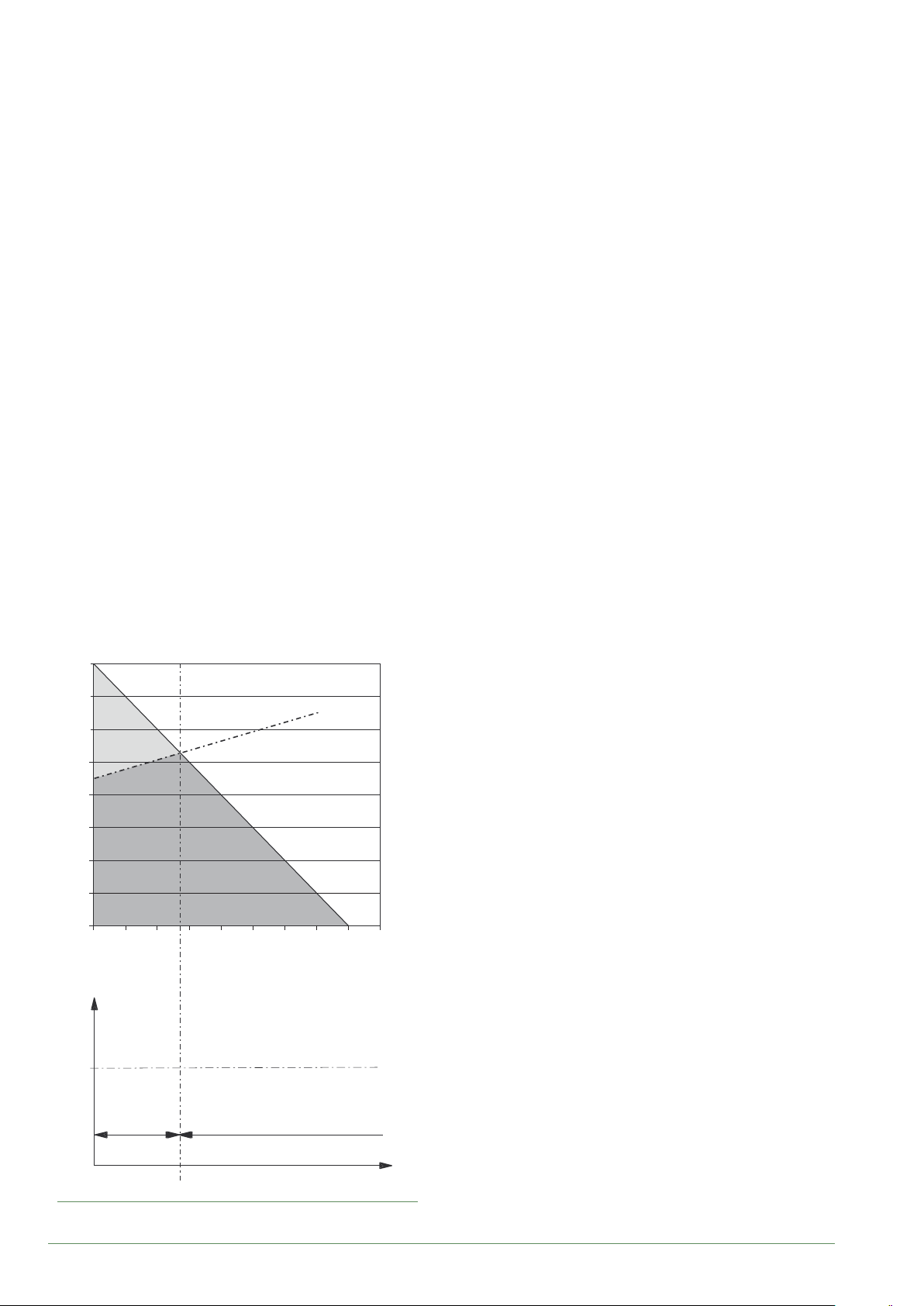
Dwelling heat loss (kW)
8
7
6
Backup
5
4
3
HP power
Heat Pump
2
1
0
-20 -15 -10 -5 0 510152025
HP +
electrical
backup
Outdoor temperature (°C)
Max
authorised HP
start-up temp.
HP only
46
Water return temperature (°C)
Outdoor temperature (°C)
g. 10 - Examples and operating limits
- 14 -
Waterstage / Installation / 2011 - EN
Page 15

• Domestic hot water (DHW) operating principle
Two domestic hot water (DHW) temperatures can be
set: comfort and reduced.
The default DHW program is set to the comfort
temperature between 00:00 and 05:00 and between
14:30 and 17:00 and to the reduced temperature for the
rest of the day. This optimises electrical consumption
while ensuring comfortable heating and water
temperatures.
The reduced temperature setpoint may be useful to
avoid restarting the DHW too often and for too long
during the day.
The production of domestic hot water (DHW) is started
when the temperature in the tank drops to 7°C below
the temperature setpoint.
The heat pump produces the domestic hot water, which
is then additionally heated, if required, by the tank's
electrical backup or by the boiler. To ensure a DHW
setpoint over 55°C, the electrical backup heating must
be left on.
Depending on the setting, the comfort temperature can
be reached 24h/day or only at night or following the
DHW program.
If the contract signed with the energy provider includes
a day/night tari, the electrical backup is subject to the
supplier’s power tari and the comfort temperature may
only be reached at night.
If no particular contract has been signed, the comfort
temperature can be reached at any time, including
during the day.
The production of DHW takes priority over heating;
nevertheless the production of DHW is managed
by cycles that regulate the amount of time assigned
to heating and production of DHW in the event of
simultaneous demand.
Anti-legionella cycles can be programmed.
• Fan convectors with integrated control system
Do not use a room sensor in the area in question.
Air energy
Ev
Electrical
energy
consumed
Dt
Cp
Cn
1kW
PAC
Heat produced
COP 4
4kW
20 °C
PAC - Heating Pump
Ev - Evaporator
Cp - Compressor
Cn - Condenser
Dt - Expansion Valve
g. 11 - Heat pump operating principle
Waterstage / Installation / 2011 - EN
- 15 -
Page 16
Installation
Installation of refrigeration
►
connections
Bend the pipes into position and make holes
for them through the oor or walls either with
their protective caps in place or after brazing.
Keep the protective caps in place or ends
brazed until the appliance is commissioned.
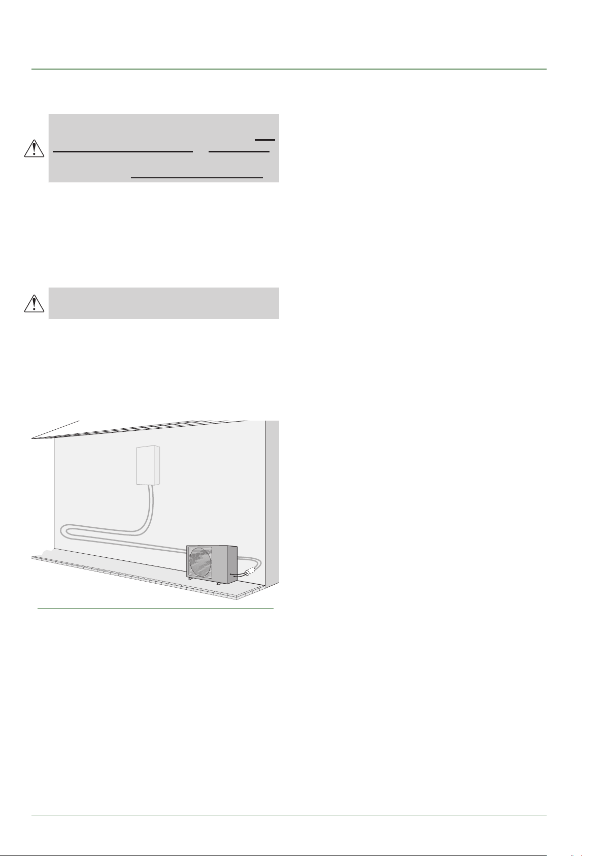
The outdoor unit must be connected to the hydraulic unit
only with brand new separately insulated copper
connections (refrigerant quality).
Maintain the same pipe diameters (g. 19).
Observe the maximum and minimum distances
between the hydraulic unit and the outdoor unit
(g. 19, page 24); the guarantee of performance and
the service lifespan of the system depend on this.
The minimum length of the refrigeration
connections for correct operation is 5 m.
The appliance's warranty will be void if it is operated
with refrigeration connections less than 5 m long
(tolerance +/- 10%).
If the refrigeration connections are exposed to
weathering or UV radiation and the insulation is not
resistant, protection must be provided.
g. 12 - Example of recommendation for layout of
refrigeration connections
- 16 -
Waterstage / Installation / 2011 - EN
Page 17

Page 18

D
Installation of the outdoor unit
►
Installation precautions
▼
The outdoor unit must only be installed
outside. If a shelter is required, it must have
broad openings on all 4 sides and installation
clearances must be observed.
• Choose the location of the appliance after discussion
with the client.
• We recommend choosing a site that is sunny but
sheltered from strong cold prevailing winds.
• The unit must be easily accessible for future installation
and maintenance work (page 20).
• Ensure that connections to the hydraulic unit can be
made easily.
• The outdoor unit is able to withstand bad weather but
avoid installing it in a position where it is likely to be
exposed to signicant dirt or owing water (under a
defective gutter for example).
• Water may ow out of the outdoor unit when it is
operating. Do not install the unit on a paved terrace;
choose a well-drained location (e.g. gravel or sand).
If installation is carried out in an area where the
temperature stays below 0°C for long periods, check
that the presence of ice does not present any danger.
A drainage pipe can also be connected to the outdoor
unit (see g. 14).
• Nothing should obstruct the air circulation through the
evaporator and out from the fan (g. 13).
• Keep the outdoor unit away from heat sources and
ammable products.
• Make sure that the unit does not disturb the
surrounding area or inhabitants (noise level, draught,
low temperature of the ejected air freezing the plants
in its path).
A ≥ 80 mm
B ≥ 100 mm
C ≥ 200 mm
D ≥ 300 mm
E ≥ 500 mm
F ≥ 600 mm
G ≥ 1000 mm
H ≥ 1500 mm
J ≥ 2000 mm
K ≥ 3000 mm
A
B
D
BB
E
H
G
B
G
G
B
A
B
B
B
D
B
B
H
B
B
D
E
E
H
B
J
F
G
g. 13 - Minimum installation clearances around the outdoor unit (all models)
- 18 -
B
B
H
B
B
H
E
B
B
E
Waterstage / Installation / 2011 - EN
H
K
F
Page 19
• The surface on which the appliance is installed must:
- Be permeable (soil, gravel, etc.).
- Support its weight easily.
- Allow a solid fastening base,
- Not transmit any vibration to the dwelling. Anti-vibratory
blocks are available as an option.
• The wall bracket cannot be used where it is likely to
transmit vibrations. Installing the unit on the ground is
preferred.
Positioning Outdoor Unit
▼
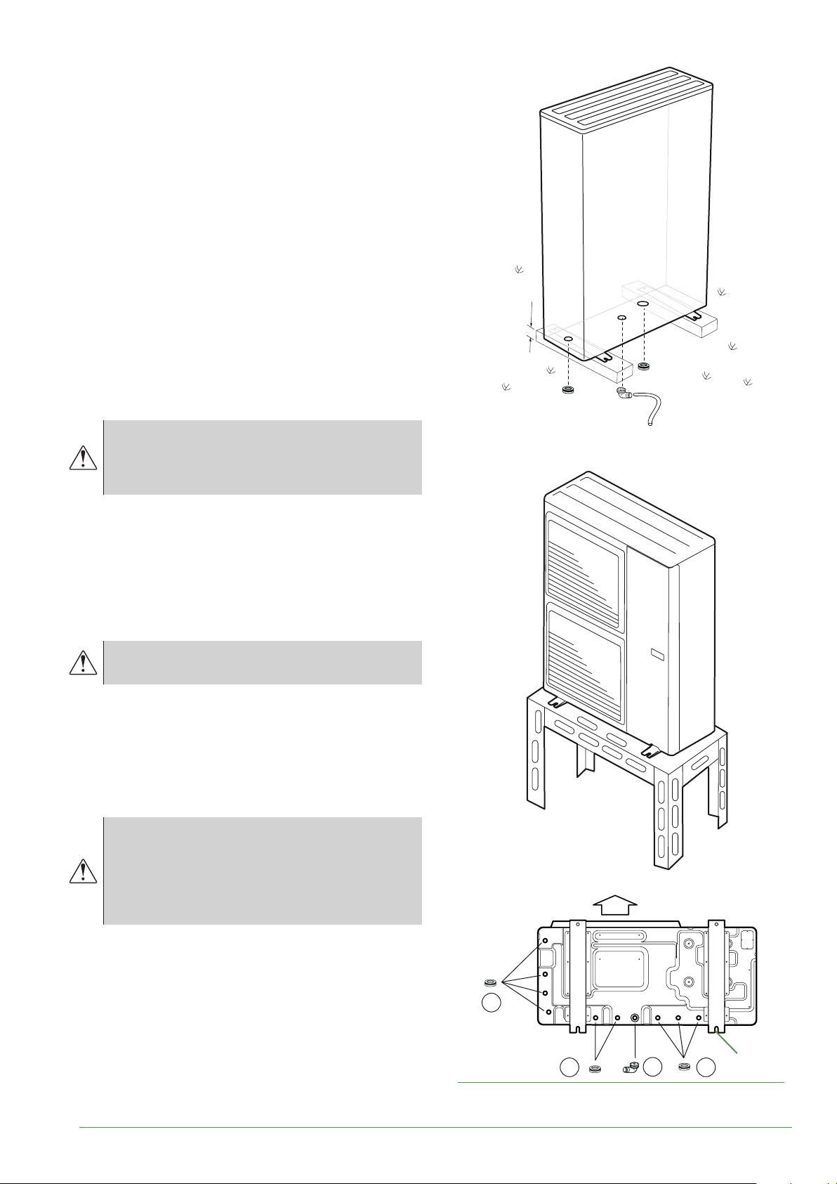
The outdoor unit must be raised at least 50 mm above
ground level. In areas prone to snow, this height should
be increased but should not exceed 1.5 m (gure 12).
- Fasten the outdoor unit by means of screws and
rubber tightening or toothed lock washers to prevent
them from coming loose.
H
In areas with heavy snowfall, if the intake and
outlet of the outdoor unit is blocked with snow,
heating may become dicult and a failure is
likely to occur.
Construct a canopy or place the unit on a high stand
(local conguration).
- Place the unit on a solid stand in order to minimise
impacts and vibrations.
- Do not place the unit directly on the ground as this will
cause problems.
Condensate drain pipe
▼
The outdoor unit can generate a large volume
of water (called condensate).
If the use of a drain pipe is necessary:
- Use the elbow provided (C) and connect a 16 mmdiameter hose for draining the condensate.
- Use the plug(s) provided (B) to block the opening of
the condensate drain pan.
Allow for the condensate to ow away under the force of
gravity (waste water, rain water, gravel bed).
If installation is carried out in an area where the
temperature stays below 0°C for long periods,
equip the drain pipe with trace heating to
avoid it icing up. Trace heating must heat not
only the drain pipe but also the bottom of the
appliance's condensate collection tank.
* In areas with heavy snowfall,
(H) must be higher than the average snow layer.
Air
Waterstage / Installation / 2011 - EN
B
4 holes
B
g. 14 - Installation of the outdoor unit evacuation of
condensates
C
(ø 12 mm)
B
- 19 -
Page 20

Installation of the hydraulic unit
►
Installation precautions
▼
• Choose the location of the appliance after discussion
with the client.
• The installation space should comply with current
regulations.
• To facilitate maintenance and allow access to the
various parts, we recommend that you provide
sucient space all the way around the hydraulic unit.
350 mm
mini
300 mm
mini
1000 mm
- If the refrigeration connection is only performed at the
end of the installation, make sure that the refrigeration
circuit caps* remain in place and tight throughout the
installation.
* (Hydraulic unit side and outdoor unit side).
- After each maintenance operation on the refrigeration
circuit and before the nal connection, take care to
put the caps back in position to avoid any pollution
of the refrigeration circuit (sealing with adhesive is
prohibited).
Positioning the hydraulic unit
▼
- Fix the bracket S securely (4 screws and plugs) to a
strong, at wall (not a light partition) ensuring that it is
correctly levelled.
350 mm
min.
mini
538 mm
min.
mini
• In accordance with EN 378-1 -2017 standard
(Refrigerating systems and heat pumps - Safety and
environmental requirements), the system's hydraulic
unit and all refrigeration connections passing through
inhabited areas must comply with the minimum room
volume requirements shown hereafter.
The minimum volume of a room (in m3) is calculated
using the formula: "uid ll load" (in kg) / 0.39.
Alternatively, you must ensure that
- The location has natural ventilation through another
room where the combined volume of the two rooms
is greater than "liquid ll load" (in kg) / 0.39 kg/m³.
The opening between the two rooms must have a door
clearance of at least 1 cm.
- Or that the location is mechanically ventilated.
Be careful not to bring ammable gas
near the heat pump during installation,
in particular when brazing is required.
The appliances are not reproof and should
not therefore be installed in an explosive
environment.
- To avoid condensation inside the condenser, remove
the refrigeration circuit caps only when making the
refrigeration connections.
300 mm
mini
min.
118 mm
188 mm
418 mm
min.
mini
(S)
g. 15 - Mounting bracket
- Hook the appliance onto its bracket S.
Weight of the appliance (full of water) = 58Kg
- 20 -
Waterstage / Installation / 2011 - EN
Page 21

10
9
19
C
7
7
C
C
C
6
5
B
B
(S)
4
3
2
1
A
A
TX20
8
19
TX20
g. 16 - Removing the casing
Waterstage / Installation / 2011 - EN
D
12
11
D
TX20
D
11
- 21 -
Page 22
Refrigeration connections
This appliance uses refrigerant R410A.
Comply with the legislation on handling of refrigerants.
Rules and precautions
►
Connections must be made on the same day
the installation is lled with gas (see para.
"Filling the installation with gas", page 26).
• Minimum tools required
- Set of pressure gauges (Manifold) with hoses
exclusively designed for HFCs (Hydrouorocarbons).
- Vacuum gauge with isolation valves.
- Vacuum pump specically for HFCs (using a standard
vacuum pump is allowed if, and only if, it is tted with
a non-return valve on the suction side).
- Flaring tool, Pipe-cutter, Deburring tool, Spanners.
- Certied refrigerant leak detector (sensitivity 5g/year).
Using tools that have been in contact with
HCFCs (R22 for example) or CFCs is prohibited.
The manufacturer declines any liability with
regard to the warranty if the above instructions
are not observed.
• Flared connections
Lubricating with mineral oil (for R12, R22)
is prohibited.
- Lubricate only with polyolester oil (POE). If POE is not
available, t without lubrication
Coat the ared surface
with POE refrigeration oil.
Do not use mineral oil.
described above, condensation will form on the
surface of the insulation material. Lastly, use insulating
sleeves whose thermal conductivity will be less than
or equal to 0.045 W/mK if the temperature is equal to
20°C. The insulation must be impermeable in order to
withstand the passage of vapour during the defrosting
cycles (glass wool is prohibited).
Shaping the refrigeration pipes
►
Bending
▼
The refrigeration pipes must be shaped only on a
bending machine or with a bending spring in order to
avoid any risk of crushing or breaking them.
Remove the insulation material from the section of
pipe to be bent.
Do not bend copper to an angle greater than 90°.
Never bend pipes more than 3 times in the
same place otherwise traces of fracturing may
appear (hardening of the metal).
Creating the arings
▼
- Cut the pipe to an appropriate length with a pipe-cutter
without damaging it.
- Carefully deburr it, holding the pipe pointing downward
to avoid introducing lings into the pipe.
- Remove the ared connection nut situated on the
valve to be connected and slide the pipe into the nut.
- Proceed to are it, letting the pipe protrude out of the
aring tool's tube.
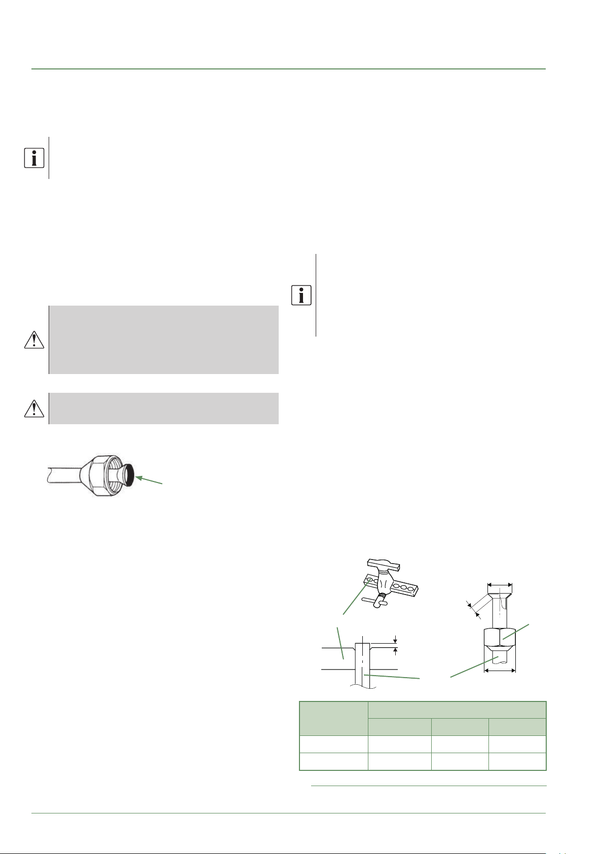
- After aring, check the state of the working radius (L).
This must not present any scratches or signs of
fracturing. Also check the dimension (B).
• Brazing the refrigeration circuit (if necessary)
- Silver brazing (40% minimum recommended).
- Brazing only with dry nitrogen internal ux.
• Other remarks
- After each maintenance operation on the refrigeration
circuit and before nal connection, take care to put
the caps back in position to avoid any pollution of the
refrigeration circuit.
- To eliminate any lings getting into the pipes, use dry
nitrogen to avoid introducing any humidity that may
adversely aect the appliance's operation. In general,
take every precaution to avoid humidity penetrating
into the appliance.
- Proceed with thermal insulation of the gas and liquid
pipes to avoid any condensation. Use pipe insulators
resistant to temperatures over 90°C. In addition, if the
humidity level in areas where the refrigerant pipes are
installed is expected to exceed 70%, protect the pipes
with pipe insulators. Use an insulating material thicker
than 15mm if the humidity level reaches 70 ~ 80%,
and an insulating material thicker than 20mm if
the humidity exceeds 80%. If the recommended
thicknesses are not observed under the conditions
- 22 -
B
-0.4
L
C
C
Flaring tool
Pipe
Dimensions in mm
Pipe ø
L B 0/
9.52 (3/8") 2.5 to 2.7 13.2 22
15.88 (5/8") 2.9 to 3.1 19.7 29
g. 17 - Flaring of the ared connections
Waterstage / Installation / 2011 - EN
Nut
are
Page 23

■ Outdoor unit
Front Side Lower
■ Hydraulic unit
Sortie dessousSortie avant Sortie latérale
g. 18 - Feeding through ared connections
Waterstage / Installation / 2011 - EN
- 23 -
Page 24

HP model Waterstage SHP
gas liquid
Outside unit connections 5/8" 3/8"
Diameter (D1) 5/8" (D2) 3/8"
Refrigeration
connections
Maximum Height Difference
Hydraulic unit connections 5/8" 3/8"
1 Without additional lling of R410A.
2 Taking into account a possible additional ll of refrigerant R410A (see "Additional lling", page 28 ).
3 Outdoor unit over hydraulic unit and heating only / Other cases.
Minimum length (L) 5
Maximum length 1 (L) 15
Maximum length 2 (L) 30
2/3
(D) 25 / 15
Hydraulic
unit
Outdoor unit
Heat Pump
Hydraulic
Heat
Pump
mini
mini
min.
5m
5m
unit
DL
DL
"Liquid” valve
“Gas” valve
"Liquid" refrigerant
connection
D2 diameter
Flared nut
Flared nut
Flared nut
Flared nut
Outdoor unit
"Gas" refrigerant
connection
D1 diameter
g. 19 - Refrigeration connections (authorised diameters and lengths)
- 24 -
Waterstage / Installation / 2011 - EN
Page 25
Checks and connection
►
The refrigeration circuit is very sensitive
to dust and humidity: check that the area
around the connection is clean and dry before
removing the plugs protecting the refrigeration
connectors.
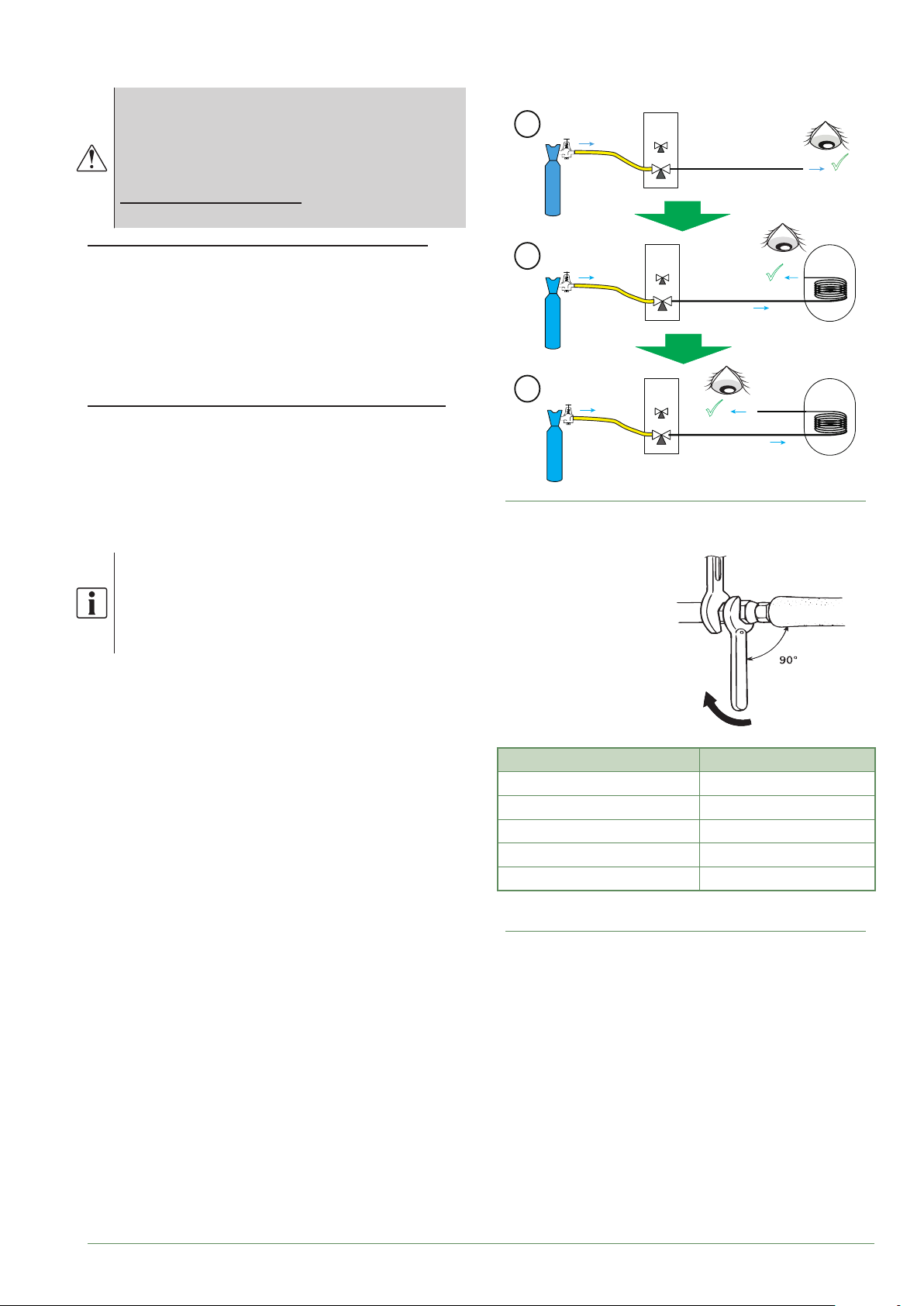
Indicated blowing value: 6 bar for minimum
30 seconds for connection of 20 m.
Checking the gas connection (large diameter).
Connect the gas connection to the outdoor unit.
Blow dry nitrogen into the gas connection and inspect
its end:
- If water or impurities emerge, use a brand new
refrigeration connection.
Otherwise, proceed with aring and connect the
refrigeration connection to the outdoor unit immediately.
Checking the liquid connection (small diameter).
Connect the liquid connection to the hydraulic unit.
Blow nitrogen into the gas-condenser-liquid
connection system and inspect its end (outdoor unit side).
- If water or impurities emerge, use a brand new
refrigeration connection.
- Otherwise, proceed with aring and connect the
refrigeration connection to the outdoor unit immediately.
UE
1
Azote
Nitrogen
2
Azote
Nitrogen
3
Azote
Nitrogen
g. 21 - Checking refrigeration connections
OU
UE
OU
UE
OU
Gas
Liaison
connection
gaz
Liaison
Gas
connection
gaz
gaz
Gas
Liaison
Liquid
connection
liquide
MH*
HIU
MH*
HIU
Take particular care to position the tube
opposite its connector so as not to risk
damaging the threads. A properly aligned
connector can be attached easily by hand
without much force being required.
- Remove the plugs from the pipes and the refrigeration
connections.
- Warning! Avoid positioning the gas pipe in front of the
pump.
- Comply with the indicated tightening torques.
Holding spanner
Torque wrench
Designation Tightening torque
Flared nut 9.52 mm (3/8") 32 to 42 Nm
Flared nut 15.88 mm (5/8") 63 to 77 Nm
Plug (A) 3/8" 20 to 25 Nm
Plug (A) 5/8" 30 to 35 Nm
Plug (B) 3/8", 5/8" 10 to 12 Nm
Plug (A) and (B) : see g. 22, page 27.
g. 20 - Tightening torques
Waterstage / Installation / 2011 - EN
- 25 -
Page 26
Filling the installation with gas
Jeu de manomètres
►
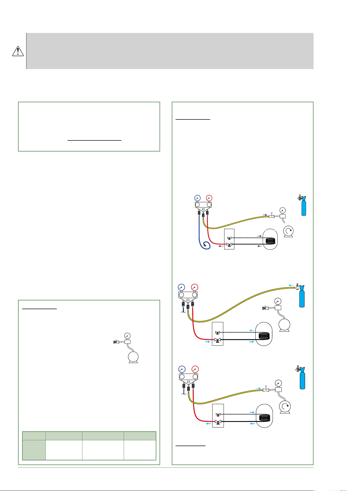
This operation is reserved for installers familiar with the legislation for handling refrigerants.
Creating a vacuum with a calibrated vacuum pump is essential (see APPENDIX 1).
Never use equipment used previously with any refrigerant other than a HFC.
Only remove the refrigeration circuit caps when performing the refrigeration connections.
If the outdoor temperature is below +10°C:
- You must use the triple evacuation method
(see APPENDIX 2).
APPENDIX 2
Triple Evacuation Method
- We recommend installing a dehydrator lter
(and this is highly recommended if the outdoor
temperature is below +5°C).
- Connect the Manifold high-pressure hose to the
lling hole (gas connection). A valve must be tted
to the vacuum pump's hose so you can shut it o.
a) Create a vacuum until the desired value is
reached and maintain this value for 30 mins
(see table in APPENDIX 1),
Set of pressure gauges
(Manifold)
(Manifold)
APPENDIX 1
Method for calibrating and checking a vacuum
pump
- Check the vacuum pump's oil level.
- Connect the vacuum pump
to the vacuum gauge as
shown in the diagram.
Flexible
Plugged
hose
bouché
- Pump down for 3 minutes.
- After 3 minutes, the pump
reaches its threshold vacuum limit and the vacuum
gauge's needle stops moving.
- Compare the obtained pressure value against the
table of values. Depending on the temperature, this
pressure should be lower than that shown in the
table.
=> If this is not the case, replace the gasket, hose
or pump.
T °C 5°C<T<10°C 10°C<T<15°C 15°C < T
Pmax
- bar
- mbar
0.009
9
0.015
15
Vacuum
gauge
Vacuomètre
Pompe
Vacuum
pump
à vide
0.020
20
Low
Basse
pression
Pressure
Lo
Hi
Haute
Pressure
pression
High
UE
OU
Connection
Liaison...
Liquid
liquide
gaz
Gas
MH
HIU
Vacuum
Vacuomètre
Gauge
Vacuum pump
Pompe à vide
b) Switch o the vacuum pump, close the valve at
the end of the service hose (yellow), connect this
hose to the expansion valve on the nitrogen bottle,
ll to 2 bar, close the hose's valve again,
Nitrogen
Hi
Haute
Pressure
pression
High
UE
OU
Connection
Liaison...
Liquid
liquide
Gas
gaz
MH
HIU
Lo
Azote
c) Connect this hose to the vacuum pump again,
switch it on and slowly open the hose's valve.
Lo
Hi
Haute
Pressure
pression
High
UE
OU
Connection
Liaison...
Liquid
liquide
gaz
Gas
MH
HIU
d) Repeat this operation at least three times.
Remember: performing these operations using
refrigerant is strictly prohibited.
- 26 -
Waterstage / Installation / 2011 - EN
Page 27
Seal test
▼
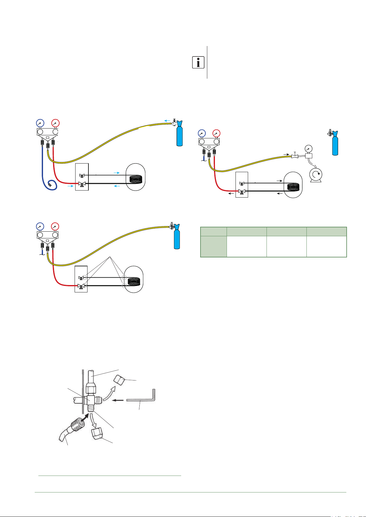
- Remove the protective plug (B) from the lling hole
(Schrader) in the gas valve (large diameter).
- Connect the high pressure hose from the Manifold to
the lling hole (g. 22).
- Connect the nitrogen bottle to the Manifold (only use
dehydrated nitrogen type U).
- Fill the refrigeration circuit with nitrogen to maximum
10 bar (gas-condenser-liquid connection system).
- Maintain this pressure in the circuit for 30 minutes.
Nitrogen
Hi
High
Haute
Pressure
Lo
pression
Liaison...
Connection
UE
OU
Liquid
liquide
Gas
gaz
MH
HIU
Azote
Max 10 bar
10 bars max.
Min 30 mins
30 mn mini
- If a pressure drop occurs, bring it back down to 1 bar
and look for leaks with a leak detector, repair and
repeat the test.
Lo
Hi
High
Haute
Pressure
pression
UE
OU
Liaison...
liquide
gaz
Vanne fermée,
Contrôle pression
Seal test
Contrôle
d’étanchéité
MH
HIU
Valve closed
Creating a vacuum
▼
The triple evacuation method (APPENDIX 2)
is strongly recommended for any installation
and especially when the outdoor temperature
is below 10°C.
- If necessary, calibrate the Manifold pressure gauge(s)
to 0 bar. Adjust the vacuum gauge to current
atmospheric pressure (≈ 1013 mbar).
- Connect the vacuum pump to the Manifold. Connect
a vacuum gauge if the vacuum pump is not equipped
with one.
Lo
Hi
Haute
Pressure
pression
High
UE
OU
Connection
Liaison...
Liquid
liquide
Gas
gaz
MH
HIU
Vacuum
Vacuomètre
Gauge
Vacuum pump
Pompe à vide
- Create a vacuum until the residual pressure* in the
circuit falls below the value given in the following
table (* measured with the vacuum gauge).
T °C 5°C<T<10°C 10°C<T<15°C 15°C < T
Pmax
- bar
- mbar
0.009
9
0.015
15
0.020
20
- Let the pump continue to operate for another 30
minutes minimum after reaching the required vacuum.
- Close the Manifold valve, then stop the vacuum pump
without disconnecting any of the hoses in place.
- Once the pressure is steady and there are no leaks,
empty the nitrogen by leaving the pressure above
atmospheric pressure (between 0.2 and 0.4 bar).
Refrigeration connection
Liaison frigorifique (gaz)
(gas)
Bouchon (A)
Vanne3voies
3-way valve
High-pressure hose (red)
Flexible haute pression
(rouge)
Allen (hex) key (4 mm)
Clé hexagonale/Allen
Filling hole
Orifice de charge
Plug (B)
Bouchon (B)
Plug (A)
(4mm)
g. 22 - Connecting the hose to the gas valve
Waterstage / Installation / 2011 - EN
- 27 -
Page 28
Filling with gas
▼
Additional lling
▼
If additional lling is required, do it before
lling the hydraulic unit with gas. Refer to
paragraph "Additional lling", page 28.
- Remove the access plugs (A) from the valve controls.
- First of all fully open the liquid valve (small) and
then the gas valve (large) using an Allen (hex) key
(anti-clockwise direction) without using excessive
force against the stop.
- Quickly disconnect the hose from the Manifold.
- Ret the 2 original caps (be sure they are clean) and
tighten them to the recommended tightening torque
indicated in the table g. 20, page 25. A seal is
achieved in the caps only with metal to metal.
The outdoor unit does not contain any additional
refrigerant allowing the installation to be bled.
Bleeding by ushing is strictly forbidden.
Final sealing test
▼
The sealing test must be carried out using a certied
gas detector (sensitivity of 5g/year).
Once the refrigeration circuit has been gassed as
described above, check that all the refrigeration
connectors are gas-tight (4 connectors). If the arings
have been made correctly, there should be no leaks.
If necessary, check the seal of the refrigeration valve
caps.
If the event of a leak:
- Return the gas to the outdoor unit (pump down).
The pressure should not drop below atmospheric
pressure (0 relative bar read on the Manifold) so as not
to contaminate the recovered gas with air or moisture.
- Redo the connection,
- Restart the commissioning procedure.
50 g of R410A
for every additional 1 metre
Length of the
connections
Additional load None 750 g
The amount needed to ll the outdoor units corresponds
to the maximum distances between the outdoor unit
and the hydraulic unit as dened here page 24. If the
distances are greater, an additional amount of R410A
is required. For each type of appliance, this additional
amount depends on the distance between the outdoor
unit and the hydraulic unit. Any additional lling with
R410A must be carried out by an approved specialist.
• Example of additional ll:
An outdoor unit which is 17 m away from the hydraulic
unit will require an additional ll of:
Additional ll = (17 - 15) x 50 = 100 g
Filling must be carried out after creating a vacuum and
before gassing the hydraulic unit, as follows:
- Disconnect the vacuum pump (yellow hose) and
connect a bottle of R410A in its place in the uid
extraction position.
- Open the bottle’s valve.
- Bleed the yellow hose by loosening it slightly on the
Manifold side.
- Place the bottle on scales with a minimum accuracy of
10g. Note the weight.
- Carefully open the blue valve slightly and check the
value shown on the scales.
- As soon as the value displayed has dropped by the
value for the calculated additional ll amount, close the
bottle and disconnect it.
- Quickly disconnect the hose connected to the
appliance.
- Proceed to ll the hydraulic unit with gas.
15 m 30 m max.
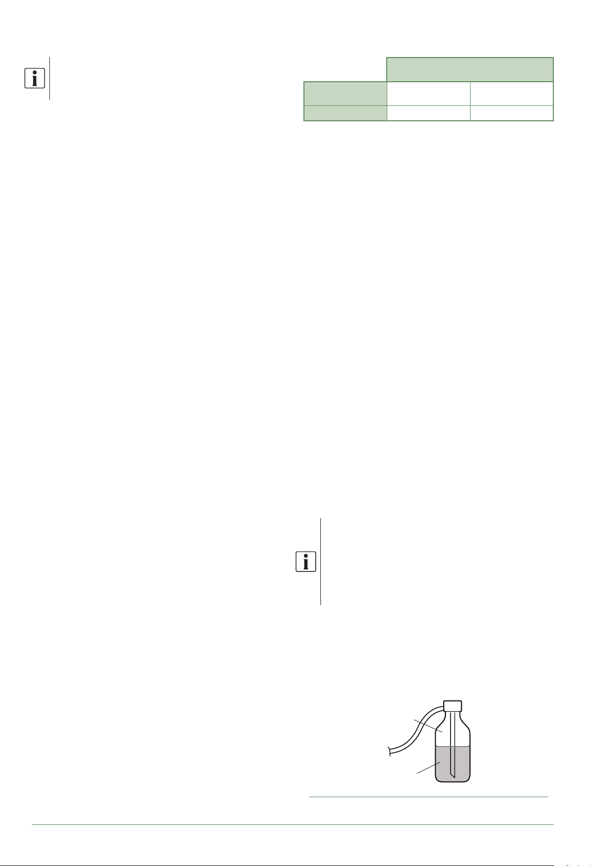
Only use R410A !
Only use tools suitable for R410A
(set of pressure gauges).
Always ll in the liquid phase.
Never exceed the maximum length or
dierence in level.
Gas
R410A
Liquid
g. 23 - Gas bottle R410A
- 28 -
Waterstage / Installation / 2011 - EN
Page 29
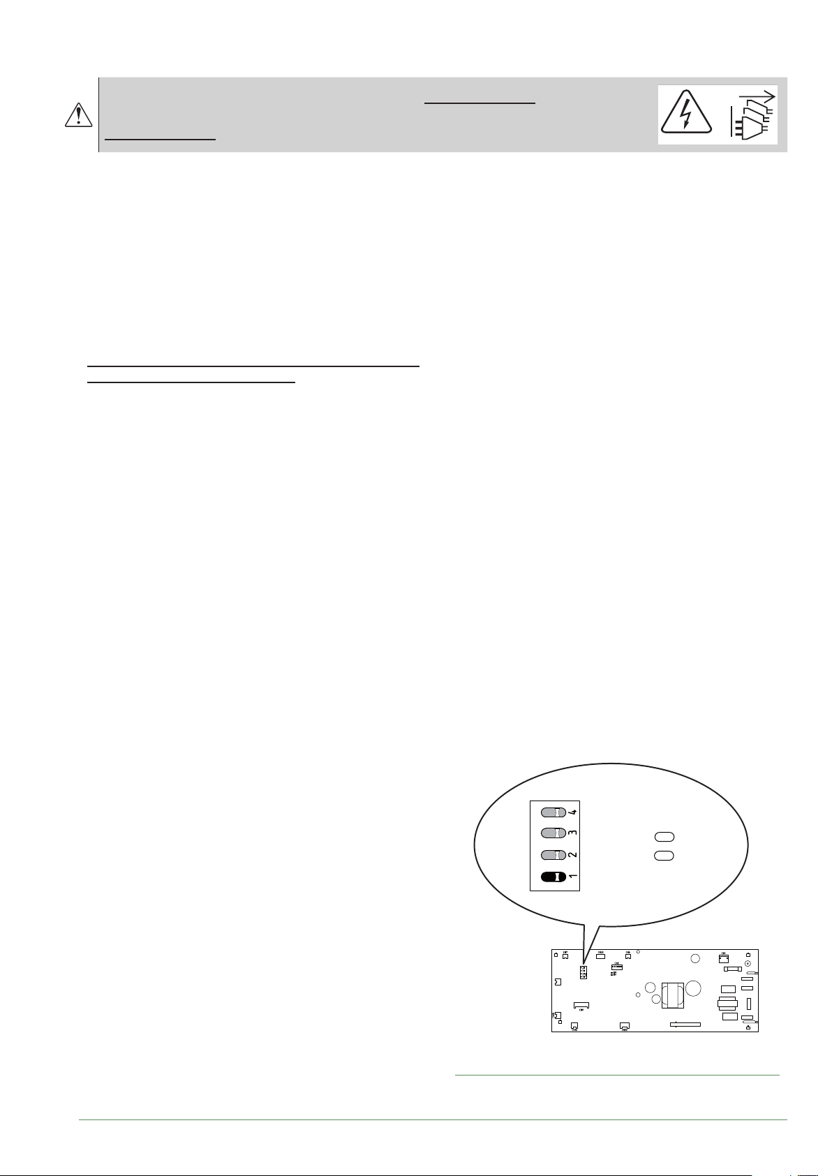
Recovering the refrigerant in the outdoor unit
▼
Before performing any maintenance, make sure that all power supplies have been cut o.
Stored energy: after cutting o the power supplies,
wait for 1 minute before accessing the internal parts of the equipment.
Perform the following procedures to collect the
refrigerant.
- 1- Switch the start/stop switch to the 0 position
(mark 3, g. 9, page 13). Disconnect the outdoor
unit's power supply.
- 2- Remove the front panel. Open the power control
box. Then turn ON the DIP SW1 on the interface
board,
- 3- Reconnect the power supply. Switch
the start/stop switch to position 1.
(The green and red LEDs start ashing; 1s on / 1s o).
The outdoor unit begins cooling operation about
3 minutes after being switched on.
- 4- The circulation pump starts.
- 5- Close the liquid valve on the outdoor unit maximum
30 secs after the outdoor unit starts.
- 6- Close the gas valve on the outdoor unit when
the pressure is below 0.02 relative bar read on the
Manifold, or 1-2 minutes after the liquid valve has been
closed, while the outdoor unit continues to operate.
- 7- Disconnect the power supply.
- 8- Recovery of the refrigerant is complete.
Notes:
- The pump down operation cannot be activated even
if DIP SW1 is set to ON while the heat pump is in
operation.
- Do not forget to switch DIP SW1 back to OFF after
the pump down operation has been completed.
- Select the heating mode.
- If the pump down operation fails, try the
operation again by turning the machine o and
opening the "liquid" and "gas" valves. Then after
2-3 minutes, restart the pump down operation.
Waterstage / Installation / 2011 - EN
DIP SW
LED2
(Green)
LED1
(Red)
ON
Interface Board
g. 24 - Location of DIP switches and LEDs on the
hydraulic unit interface board
- 29 -
Page 30

Hydraulic connections
Connecting the hydraulic unit to the heating circuit
►
Flushing the installation
▼
Before connecting the hydraulic unit to the installation,
rinse out the heating system correctly to eliminate
any particles that may aect the appliance's correct
operation.
Do not use solvents or aromatic hydrocarbons (petrol,
paran, etc.).
In the case of an old installation, provide a suciently
large decanting pot with a drain on the return from the
boiler and at the lowest point in the system in order to
collect and remove any impurities.
Add an alkaline product and a dispersant to the water.
Flush the installation several times before proceeding
to the nal lling.
Connections
▼
The heating circulation pump is built into the hydraulic
unit.
Connect the central heating pipes to the hydraulic unit
correctly according to the direction of circulation.
The pipe between the hydraulic unit and the heat
collector must be at least one inch in diameter
(26x34 mm).
Calculate the diameter of the pipes based on ow rates
and lengths of the hydraulic systems.
Tightening torque: 15 to 35 Nm.
Use union connectors to make it easier to remove the
hydraulic unit.
Try to use connection hoses to avoid transmitting noise
and vibrations to the building.
Connect the drains from the drain valve and the safety
valve to the main sewer system.
Verify that the expansion system is correctly connected.
Check the expansion vessel pressure (pre-inated to 1
bar) and the safety valve is calibrated.
The ow rate of the installation must be at least equal
to the minimum value mentioned in the specications
table "General characteristics", page 7.
The installation of a regulator (other than those included
in our congurations) which reduces or stops the ow
through the hydraulic unit is prohibited.
- 30 -
Waterstage / Installation / 2011 - EN
Page 31
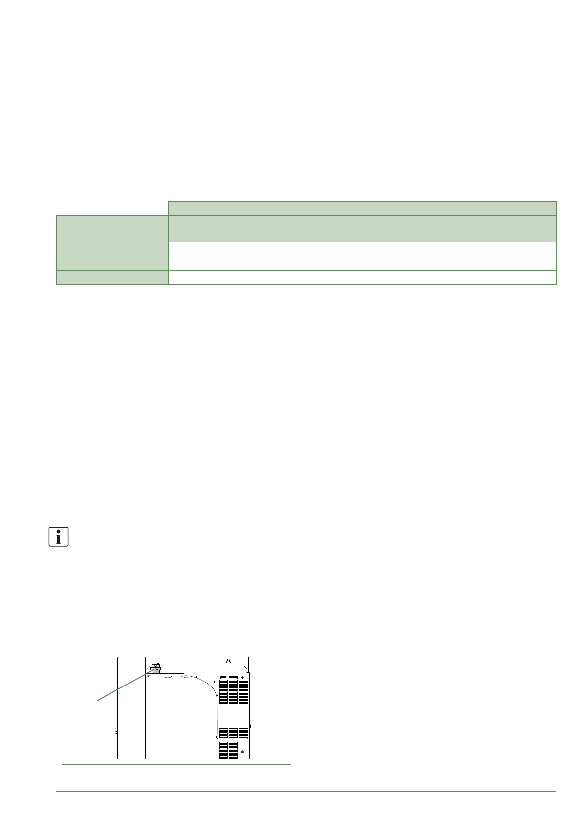
Volume of the heating system
▼
You must maintain the minimum installation water
volume. Install a buer tank on the return from the
heating circuit in case the volume is lower than this
value. Where the system is tted with one or more
thermostatic valves, you must ensure that this minimum
water volume is able to circulate.
Min. volume in litres PER CIRCUIT (excl. HP)
Appliance
Waterstage SHP 16 110 98 55
Waterstage SHP TRI 15 102 90 50
Waterstage SHP TRI 17 119 106 60
Filling and bleeding the installation
►
Check the pipe xings, tightness of the connectors and
the stability of the hydraulic unit.
Check the direction in which the water is circulating and
that all the valves are open.
Proceed to ll the installation.
Do not operate the circulation pump during lling. Open
all the drain valves in the installation and the bleeder
valve on the hydraulic unit to expel the air contained in
the pipes.
Close the drain valves and add water until the pressure
in the hydraulic circuit reaches 1 bar.
Check that the hydraulic circuit has been bled correctly.
Check there are no leaks.
After the " Commissioning", page 44, and once the
machine has started, bleed the hydraulic unit again.
Mandatory
Fan-coil
Recommendation
Radiators
Recommendation
Heating-cooling oor
Precise lling pressure is determined by the
water pressure in the installation.
P
g. 25 - Hydraulic unit automatic bleeder valve
Waterstage / Installation / 2011 - EN
- 31 -
Page 32
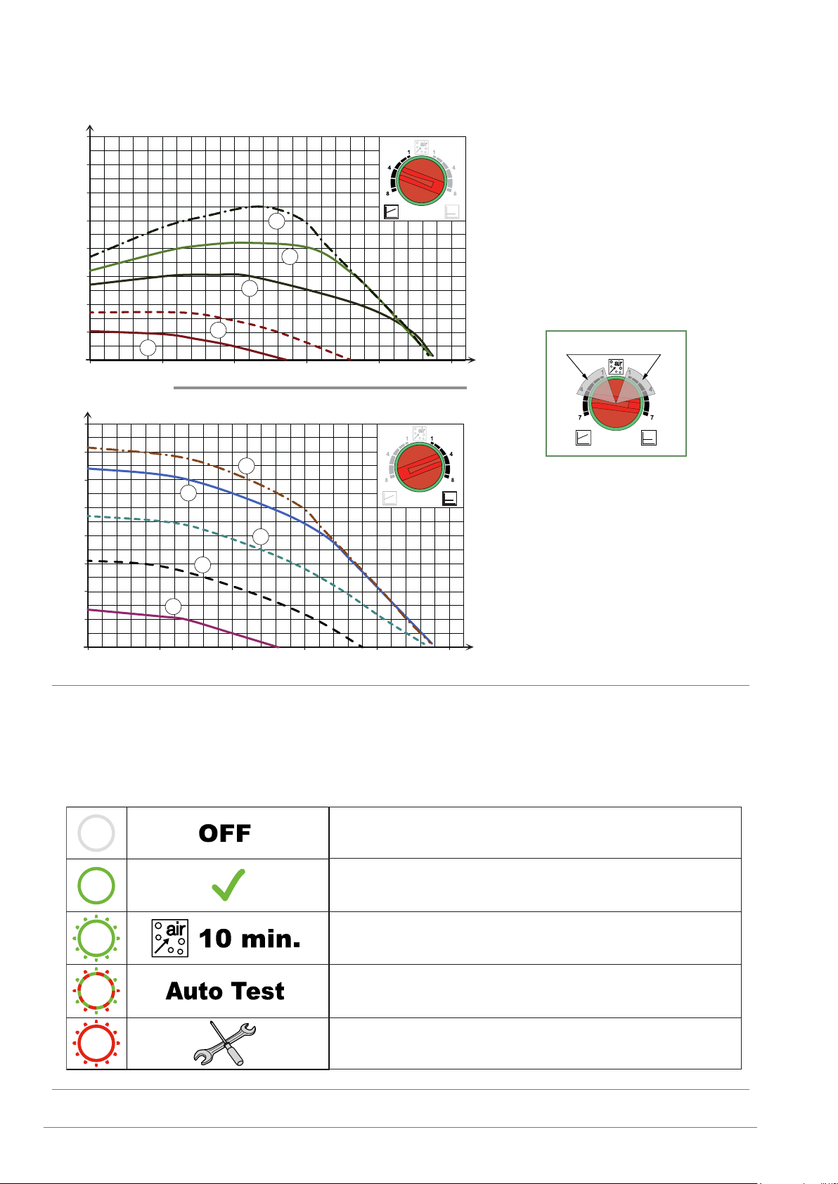
Heating circulation pump speed settings
►
mCE
1 mbar=10 mmCE=100 Pa
8
7
6
5
4
88
77
3
55
2
1
1
3
0
0 0,5 1 1,5 2
mCE
1
1 mbar=10 mmCE=100 Pa
8
7
6
88
5
77
Variable pressure
The circulation pump varies the water
pressure depending on the ow rate.
Recommended for an installation tted with
radiators (particularly any system with
thermostatic valves or zone solenoids).
Ne pas utiliser cette zone
Do not use these zones
3
3
/h
1,5 20,50
m
m/h
4
3
3
55
2
1
1
0
0 0,5 1 1,5 2
1
1,5 20,50
g. 26 - Available hydraulic pressures and ow rates
LED O:
The circulation pump is not working, no power supply.
Green LED On:
The circulation pump is operating normally.
Green LED ashing:
Venting mode in operation (10 minutes).
m
Constant pressure
The circulation pump maintains a constant
water pressure whatever the ow rate.
Recommended for an installation with
constant pressure drops such as an
underoor heating system.
3
3
/h
m/h
g. 27 - Operating signals of the HP circulation pump
- 32 -
Red/green LED ashing:
Operating error with automatic restart.
Red LED ashing:
Operating error.
Waterstage / Installation / 2011 - EN
Page 33
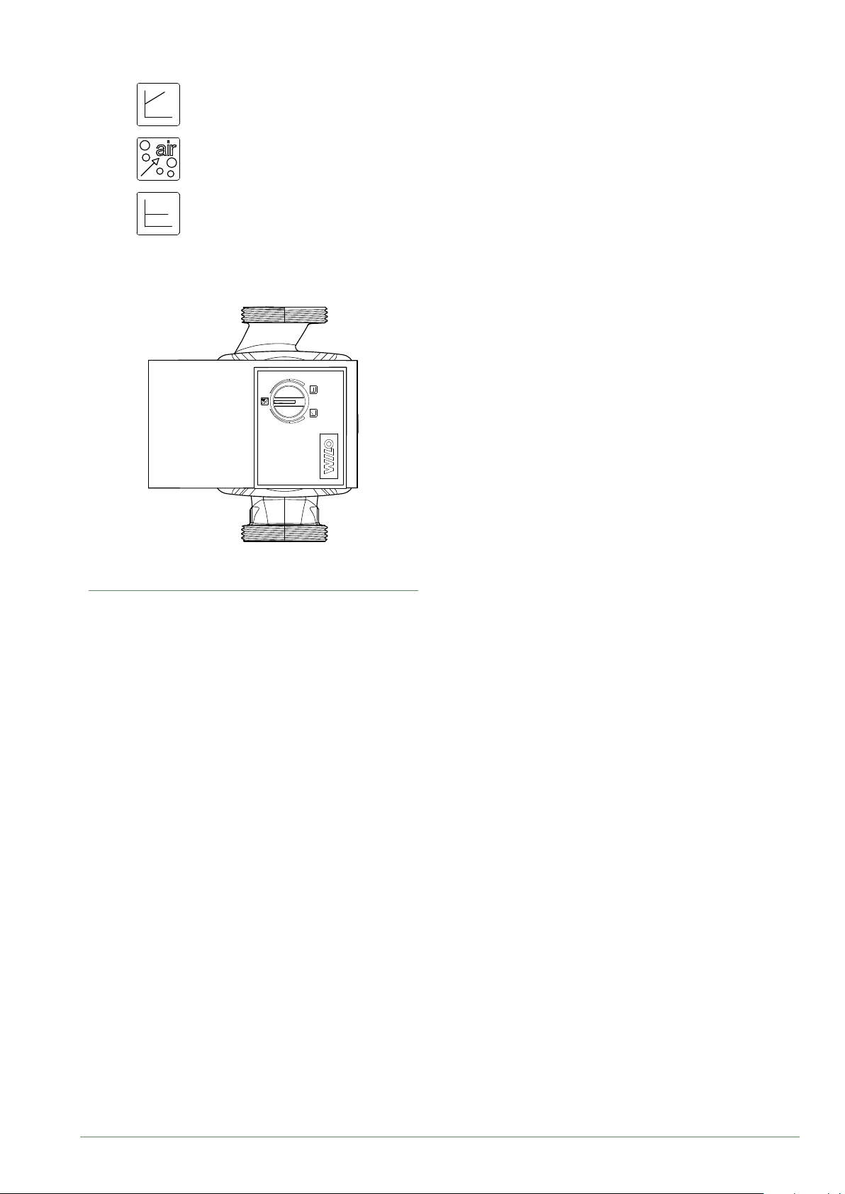
Variable pressure
Pression variable
Gas venting
Dégazage
Constant pressure
Pression constate
Circulation pump fouled or stuck:
If the motor becomes stuck, a start-up cycle is launched.
If the motor remains stuck, it will be permanently
stopped.
Cut o the power supply to the circulation pump for
30 secs in order to free it and allow a new start-up
cycle to begin.
g. 28 - Circulation pump control button
Waterstage / Installation / 2011 - EN
- 33 -
Page 34
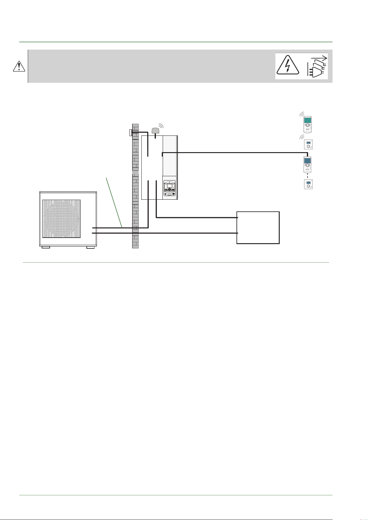
Electrical connections
Before any maintenance operation,
ensure that the general power supply is switched o.
Electrical installation must be performed in accordance with current regulations.
The electrical diagram for the hydraulic unit is shown on g. 43, page 72.
Wireless remote control (option)
Outside sensor
Cable 2 x 0.75 mm²
Interconnection between
outdoor unit and hydraulic unit
Wireless room thermostat (option)
Remote control (option)
Phase, Neutral, Earth, Communication bus)
Cable 4 G 1.5 mm²
Room thermostat (option)
OK
ESC
2
3
1
4
0
bar
Electrical backup power supply
(see table below)
General power supply
(see table below)
g. 29 - Overall layout of electrical connections for a simple installation (1 heating circuit)
or
or
Cable 2 x 0.5 mm²
or
Cable 2 x 0.5 mm²
Electrical
Board
- 34 -
Waterstage / Installation / 2011 - EN
Page 35
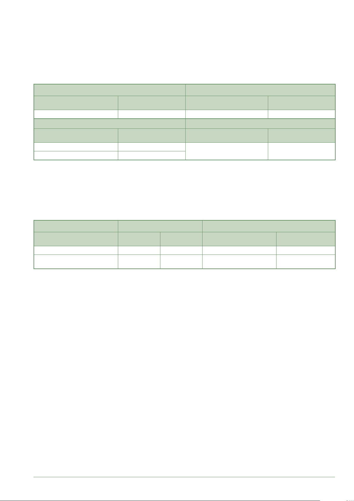
Cable dimensions and protection rating
►
These cable dimensions are provided for information purposes only and do not exempt the installer from checking
that these dimensions match requirements and comply with current standards.
• Outdoor Unit Power Supply
Single phase heat pump Electricity supply 230 V - 50 Hz
Model
Waterstage SHP 16 6300 W 3 G 6 mm² 32 A
3 phase heat pump Electricity supply 400 V - 50 Hz
Model Maximum power
Waterstage SHP TRI 15 6770 W
Waterstage SHP TRI 17 7400 W
Max. power
consumption
Connection cable
(phase, neutral, earth)
Connection cable
(3 phases, neutral, earth)
5 G 2.5 mm² 20 A
(1)
(1)
Circuit breaker
C curve
Circuit breaker
C curve
• Interconnection between outdoor unit and hydraulic unit
The hydraulic unit is powered by the outdoor unit by means of a 4 G 1.5 mm² cable
(phase, neutral, earth, communication bus).
• Electrical backup power supply
The hydraulic unit contains a electrical backup circuit (and a second optional) installed in the storage tank.
Heat pump Electrical backups Electrical backup power supply
Model Power
Waterstage SHP 16 2 x 3 kW 26.1 A 3 G 6 mm² 32 A
Waterstage SHP TRI 15
Waterstage SHP TRI 17
(1)
Cable type 60245 IEC 57 or 60245 IEC 88.
9 kW 3 x 13 A 4 G 2.5 mm² 20 A
Nominal
current
Connection cable
(phase, neutral, earth)
(1)
Circuit breaker
C curve
• DHW power supply (option)
The DHW section is powered directly via a 3 G 1.5 mm² cable (phase, neutral, earth).
Protection by rated circuit breaker (16 A - C curve).
Waterstage / Installation / 2011 - EN
- 35 -
Page 36
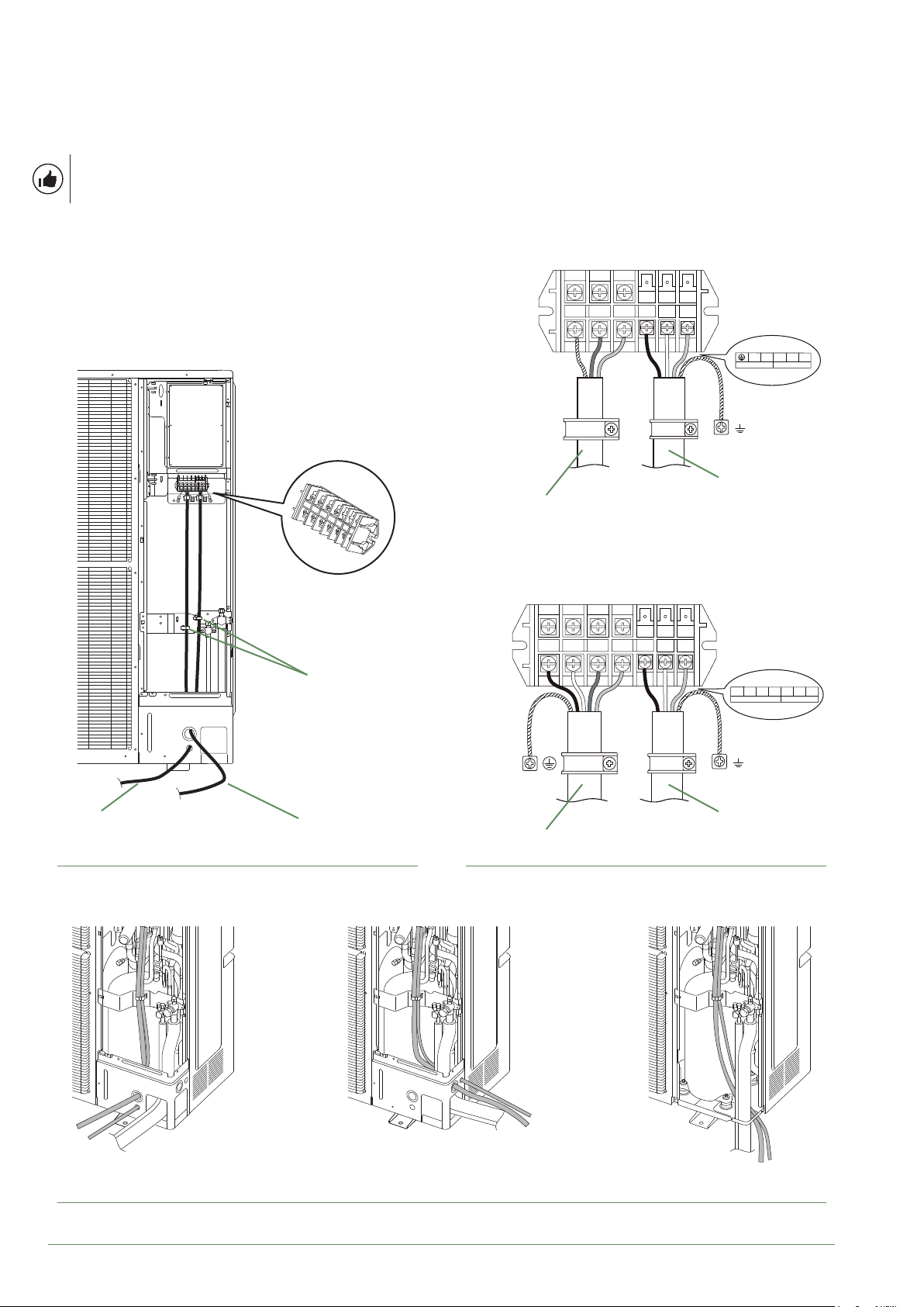
Electrical connections on the outdoor unit side
►
Access to connection terminals:
- Remove the front plate. Remove the screws and front panel.
- Make the connections according to the diagram(s) g. 34, page 40.
Use cable clamps to prevent any power cables from being disconnected accidentally.
■ Waterstage SHP 16
Terminal
L N 1 2 3
POWER INDOOR UNIT
Terminal
Cable clamp
Interconnection
between outdoor unit
and hydraulic unit
electricity supply
Main
g. 30 - Access to outdoor unit's terminal block
Interconnection
Main
electricity supply
between outdoor unit
and hydraulic unit
■ Waterstage SHP TRI 15
Waterstage SHP TRI 17
Terminal
L1 L2 L3 N 1 2 3
POWER INDOOR UNIT
Interconnection
Main
electricity supply
g. 31 - Connections of the outdoor unit's terminal block
between outdoor unit
and hydraulic unit
front
side
g. 32 - Feeding cables and refrigeration connections from the outdoor unit
- 36 -
Sortie dessousSortie latérale Sortie avant
lower
Waterstage / Installation / 2011 - EN
Page 37

Page 38
Electrical connections on the hydraulic unit side
►
Access to connection terminals:
- Remove the front panel (2 screws).
- Open the power control box.
- Make the connections according to the diagram (g. 34).
Do not place the sensor and power supply lines parallel
to each other to avoid interference due to voltage spikes
in the power supply.
Make sure that all electrical cables are housed in the
areas provided for this purpose.
Interconnection between outdoor unit
▼
and hydraulic unit
Match up the terminal block markers on the hydraulic
unit to those of the outdoor unit exactly when connecting
the interconnection cables.
An incorrect connection could result in the destruction
of one or other of the units.
Electrical backups
▼
If the heat pump is not installed with a boiler connection:
- Connect the power supply for the backup to the
electrical panel.
Boiler connection (optional)
▼
If the boiler connection option is used, the
electric backup option must not be connected.
- Please refer to the instructions supplied with the boiler
connection kit.
- Please refer to the instructions supplied with the boiler.
Second heating circuit (optional)
▼
- Refer to the instructions supplied with the double
hydraulic circuit kit.
DHW tank with electrical backup heating
▼
(optional)
If the installation is tted with a DHW tank :
- Please refer to the instructions supplied with the DHW kit.
- Please refer to the instructions supplied with the DHW tank.
You must equipped the DHW electrical backup
heating with a manual reset thermostat.
Contract with Energy Supplier
▼
The heat pump can be set to operate within particular
types of energy contract, e.g. o-peak, day/night.
In particular, domestic hot water (DHW) at the comfort
temperature will be produced at o-peak times when
electricity is at its cheapest.
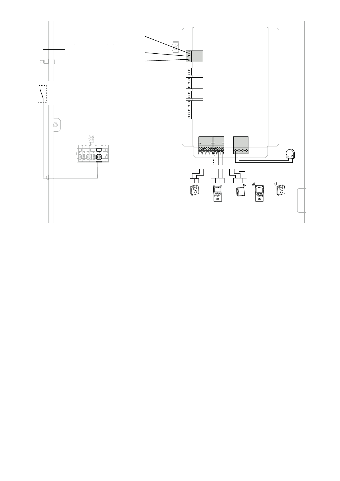
- Connect the "Power Provider" contact to input EX2.
- Set the DHW conguration to "O-Peak".
• 230V on input EX2 = "Peak Hours” information
activated.
Power limitation or EDR (Energy Demand
▼
Reduction)
Power limitation is designed to reduce electricity
consumption when it is too high for the contract signed
with the energy supplier.
- Connect the power limiter device to input EX1.
Heat pump and DHW backups will be shut o in the
event of over-consumption by the dwelling.
• 230 V on input EX1 = power limitation in progress.
Faults external to the heat pump
▼
Any component which reports back information
(Underoor heating safety switch, thermostat, pressure
switch, etc.) may signal an external problem and stop
the heat pump.
- Connect the external component to input EX3.
• 230 V on input EX3 = heat pump stopped
(system displays Error 369).
- 38 -
Waterstage / Installation / 2011 - EN
Page 39
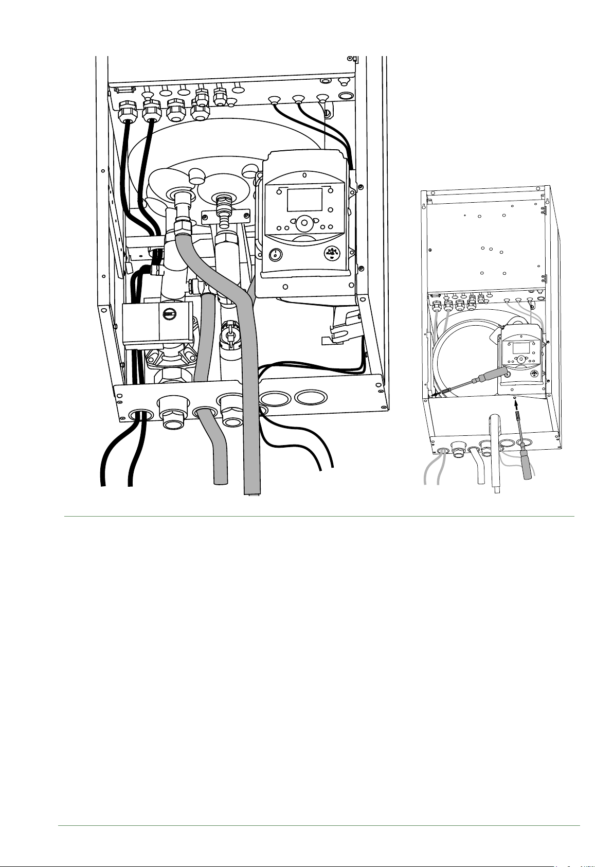
Power cables
g. 33 - Cable passages
Sensor cables
Waterstage / Installation / 2011 - EN
- 39 -
Page 40
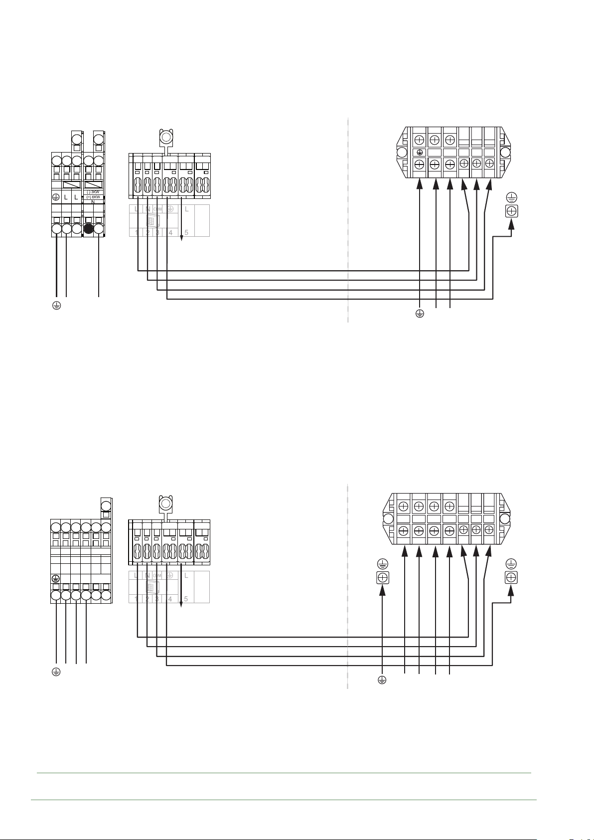
■ Waterstage SHP 16
1 2 3
L
Power supply for
Electrical backup
single phase 230 V
N
5
4
6
towards external
component contact*
Interconnection
between outdoor unit
and hydraulic unit
brown
blue
red
green/yellow
Single phase outdoor unitHydraulic unit
L N
L
Electricity supply
single phase 230 V
1 2 3
N
■ Waterstage SHP TRI 15
Waterstage SHP TRI 17
1 2 3
1 2 3 4 5 6
COMMUN
L1 L2 L3
L1 L2 L3
Power supply for
Electrical backup 3
phase 400 V
5
4
6
towards external
component contact*
brown
blue
red
green/yellow
Interconnection
between outdoor unit
and hydraulic unit
3 phase outdoor unitHydraulic unit
L2 L3 N
L2
L1
Electricity supply
3 phase 400 V
L3
1 2 3L1
N
g. 34 - Connection to terminal blocks and power relay
- 40 -
Waterstage / Installation / 2011 - EN
Page 41
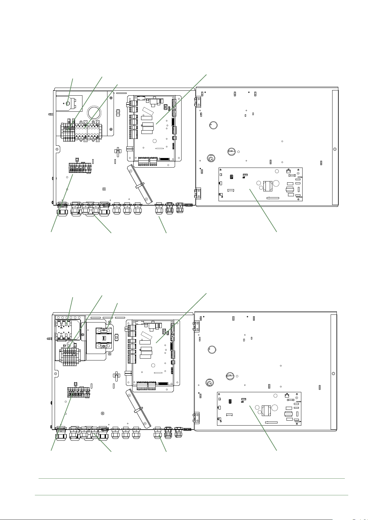
■ Waterstage SHP 16
Safety thermostat
Terminal
Power supply terminal block
Power Relay for electric backup
Cable grommets (power)
HP controller
Cable grommets (sensors)
Interface Board
■ Waterstage SHP TRI 15
Waterstage SHP TRI 17
Safety thermostat
Power supply terminal block
HP controller
Static relay for electric backup
Terminal
g. 35 - Description of the hydraulic unit's electrical control box
Waterstage / Installation / 2011 - EN
Cable grommets (power)
Cable grommets (sensors)
Interface Board
- 41 -
Page 42

Outside sensor
►
The outside sensor is required for correct operation of
the heat pump.
Please see the tting instructions on the sensor’s
packaging.
Place the sensor on the coldest side of the building,
generally the northern or north-western side.
It must not be exposed to morning sun.
It must be installed so as to be easily accessible but at
least 2.5m from the ground.
It is essential that it is not placed near any sources of
heat such as ues, upper parts of doors and windows,
near extractor vents, under balconies and eaves,
or anywhere which would insulate the sensor from
variations in the outdoor air temperature.
- Connect the outside sensor to connector X84
(terminals M and B9) on the heat pump control board.
Room sensor (optional)
►
The room sensor (room unit) is optional.
Please see the tting instructions on the sensor’s
packaging.
The sensor must be installed in the living room area on
an unobstructed wall. It must be installed so as to be
easily accessible.
Avoid direct sources of heat (chimney, television,
cooking surfaces, sun) and draughty areas (ventilation,
door, etc.).
Draughts in buildings are often brought about by cold air
blowing through the electrical ducting. Lag the electrical
ducts if there is a cold draught behind the room sensor.
Installing a room sensor
▼
• Room thermostat
- Connect the sensor to the X86 connector of the heat
pump’s regulator board using the connector provided
(terminals 1, 2).
• Room thermostat radio
- Please refer to the instructions.
Installing a room control unit
▼
• Room control unit
- Connect the sensor to the X86 connector of the heat
pump’s regulator board using the connector provided
(terminals 1, 2 and 3).
• Room control unit radio
- Please refer to the instructions.
Fan convector zone
▼
If the installation is equipped with fan convectors or
dynamic radiators, do not use a room sensor.
- 42 -
Waterstage / Installation / 2011 - EN
Page 43
Power shedding or EJP
Power limitation or EDR
(peak day removal)
(Energy Demand Reduction)
Tariffs, peak times/off-peak times,
Taris, peak times/o-peak times,
External component
contact*
External component contact*
(faults, load
(faults, power limiter, electricity meter)
shedder, power meter)
day / night
day/night
External fault
External fault
EX1
EX2
EX3
X11
X86
L
6
5
or
** Room
thermostat
T55
** Room
control unit
T75
* If the control device does not provide a potential-free contact, the contact must be relayed to create equivalent wiring. In all cases, please
refer to the instruction manuals for the external components (load shedder, power meters) to create the wiring.
** Option
The connection of terminal 3 of the room control unit is not mandatory (lighting of the room control unit).
M B9
654
12 1 3 2
or
X84
654
13 2
or
** Room control
unit radio
T78
Outside
Outdoor
sensor
sensor
** Room
thermostat
radio T58
g. 36 - Connections on the heat pump controller (accessories and options)
Waterstage / Installation / 2011 - EN
- 43 -
Page 44

Commissioning
- Close the installation's main circuit breaker.
Upon initial start-up (or in winter), to preheat the
compressor, engage the installation's main circuit
breaker (outdoor unit power supply) several
hours before starting any tests.
- Press the heat pump's Start/Stop button.
To ensure that inputs EX1, EX2 and EX3 operate
correctly: Check that the electricity supply's
neutral phase polarity has been respected.
When the power is switched on and every time that the ON/
OFF button is switched o and then switched on again,
the outdoor unit will take approximately 4 minutes to
start up, even if the setting is requesting heating.
- Engage the start/stop switch.
To ensure that inputs EX1, EX2 and EX3 operate
correctly: Check that the live-neutral polarity of
the power supply is correct.
When the power is switched on and every time that the
ON/OFF button is switched o and then switched on
again, the outdoor unit will take approximately 4 minutes
to start up, even if the setting is requesting heating.
The display can show error 370 when the
appliance (re)starts. Do not be concerned,
the communication between the outdoor and
hydraulic unit will re-establish itself in a few
moments.
During the regulator initialisation phase, the display
shows all the symbols and then "Data, update" and then
"State heat pump".
- Make all the specic adjustments to the setting.
(Installation conguration):
- Press OK.
- Hold down the key for 3s and select the level of
access used with the aid of the knob. .
- Conrm with the key OK.
- Parameter the heat pump's setting
(Consult the settings' list
On commissioning (or the case of error 10), the electrical
back-up heaters are liable to start up even if the outdoor
temperature at the time is above the heaters’ trigger
temperature.
The regulating system uses an average initial outdoor
temperature of 0°C and requires some time to update
this temperature.
To avoid this situation, the sensor must be connected
correctly. Re-initialise parameter 8703 (commissioning
level, consumer diagnostic menu).
- 44 -
Waterstage / Installation / 2011 - EN
Page 45

Conguring room thermostat
►
(wireless)
To congure the room thermostat and connect it to the
appropriate heating zone:
- Hold down the presence key for more than 3 seconds.
The room thermostat displays RU and a number
ashes.
- Turn the wheel to choose the zone (1, 2).
If the installation is tted with 2 room thermostats,
- First connect one room thermostat and congure
it in zone 2,
- Then connect the other room thermostat and
congure it as default in zone 1.
Conguring room control unit
►
(wireless)
- Hold down the presence key; the room
thermostat displays P1 and a ashing number.
1: Automatic recording: a correction of the setting
with the button is adopted without any particular
conrmation (timeout) or by pressing the mode key.
2: Recording with conrmation: a correction of the
setting with the button is not adopted until the mode
key is pressed.
- Press the presence key again; the room thermostat
displays P2 and a ashing number.
0: OFF: all the operating elements are engaged.
1: ON: the following operating elements are locked:
- Switching over the heating circuit's operating
mode,
- Adjusting the comfort setting,
- Changing the operating level.
The room thermostat displays OFF for 3 seconds when
a locked button is pressed.
During commissioning, after an initialisation period of
approx. 3 minutes, the user’s language must be set:
- Press OK.
- Choose menu "Operator section".
- Choose language.
- Select the language (English, Deutsch, Français,
Italiano, Nederlands, Español, Português, Dansk…).
In the case of 2 heating circuits.
- Choose the allocation of the room control unit
(room appliance 1 or 2…) line 40* (see page 51).
- According to the allocation selected check and, if
necessary, modify the settings for lines 42*, 44*, 48*
(see page 51).
Line Function
40 I Use as... Room appliance 1, 2, P,
This line regulates the use of the room control unit. Depending on how it is used, other settings will be necessary
(lines 42, 44, 48).
42 I Appliance allocation 1 Heating circuit 1,
44 I Operation HC2 (command HC2) Commonly with HC1,
This function enables you to choose whether you wish the room thermostat (as an option) to act on both zones or just
a single zone.
Setting range
or display
User interface 1, 2, P,
Service appliance
Heating circuit 1 & 2,
Heating circuit 1 & P,
All the heating circuits
Independent
Setting
increment
Basic
setting
Room
appliance 1
Heating
circuit 1
Commonly
with HC1
48 I Occupancy control switch function Without,
Heating circuit 1,
Heating circuit 2,
Common
* These parameter lines are only accessible from the room control unit.
Waterstage / Installation / 2011 - EN
- 45 -
Page 46
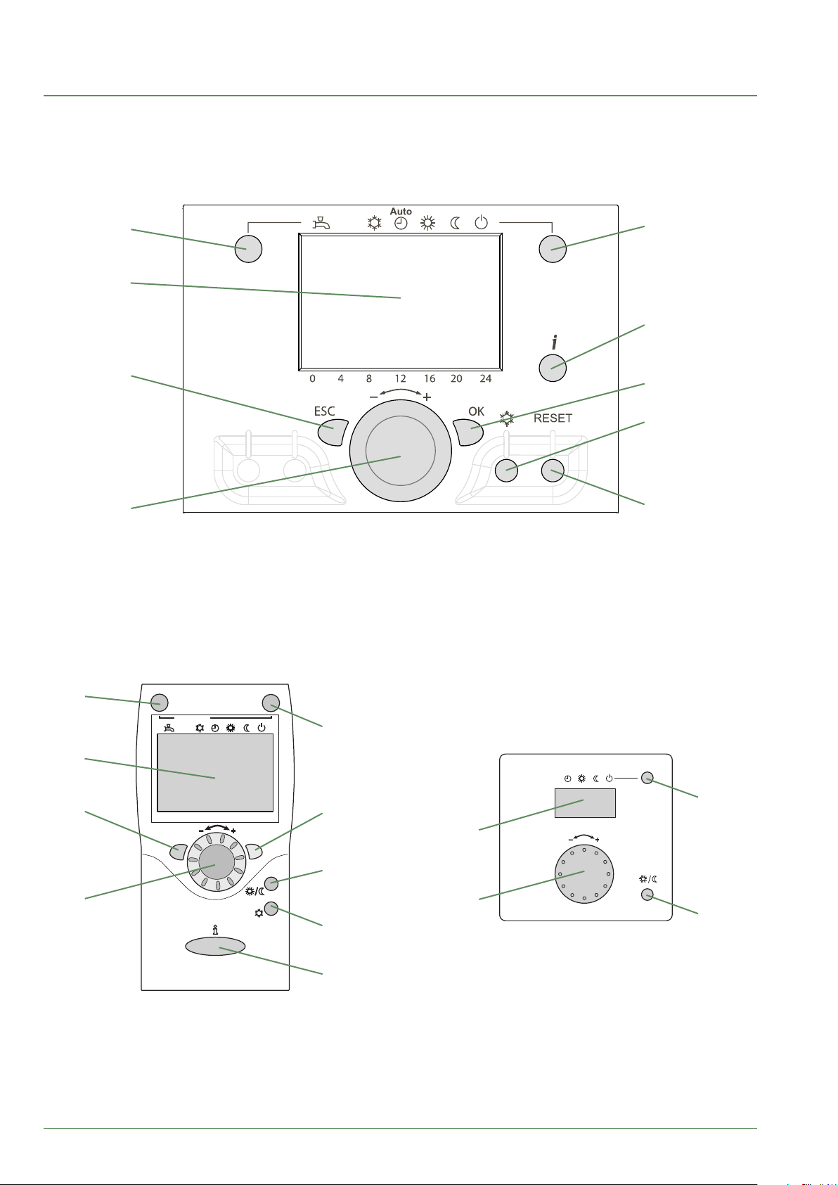
Controller Interface
The user interface, the central ambient unit (option) and the ambient sensor
►
(option)
1
5
2
6
3
7
8
4
9
1
Auto
2
5
Auto
5
3
0 4 8 12 16 20 24
ESC
OK
4
7
11
2
°C
10
11
8
6
- 46 -
Waterstage / Installation / 2011 - EN
Page 47
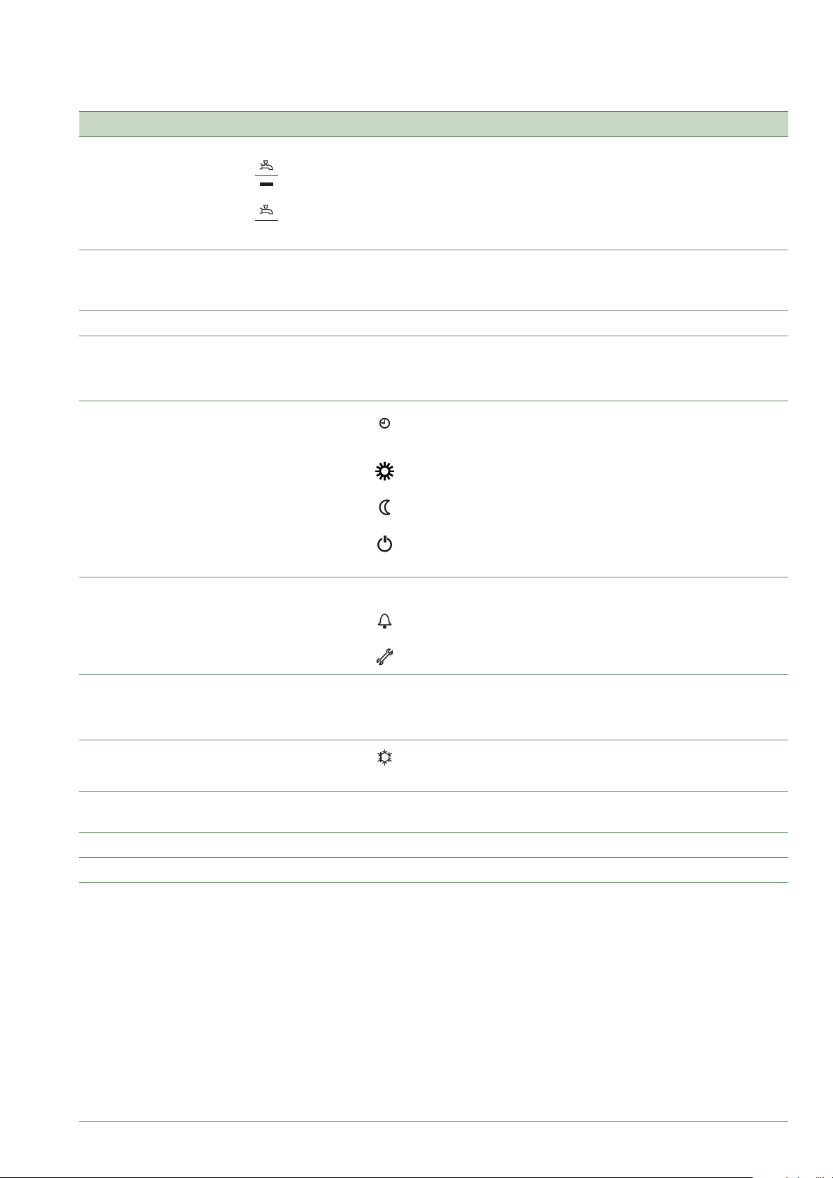
Ref. Functions - Denition of the functions
Arrêt
Auto
1 Selecting the DHW operation
Marche
- Start: Production of DHW in function of the timer programme.
- Stop: Production of the DHW stopped with antifreeze function of the
domestic water active.
- Manual start button: Press the DHW button for 3 s (switches from
"reduced" to "comfort" until the DHW timer programme is switched again).
2 Digital display - Check the operation, read the current temperature of the heating
operation, or a possible fault.
- View the settings.
3 "ESC" output - Exit the menu.
4 Navigation and setting - Setting the comfort temperature value.
- Menu selection
- Setting the parameters.
5 Selecting the heating operation
-
Service heating according to the heating programme
(automatic summer/winter switching).
- Permanent comfort temperature.
- Permanent reduced temperature.
- "Stand-by" operation with antifreeze protection (provided that the
electrical power supply of the heat pump is not interrupted).
6 Displaying information - Miscellaneous information (see "Information display", page 66).
- Reading the error codes (see " Fault Diagnosis", page 74).
- Information on maintenance, special operation.
7 Validation "OK" - Enter the selected menu.
- Validate the parameter settings.
- Validate the comfort temperature value setting.
8 Selection of the refresh mode
- Service cooling according to the heating programme
(automatic summer/winter switching).
9 Reset
(Press and relief)
- Reset the parameters and cancel the error messages.
Do not use during normal operation
10 Setting button - Setting the comfort temperature value.
11 Presence button - Comfort / reduced switching.
Waterstage / Installation / 2011 - EN
- 47 -
Page 48
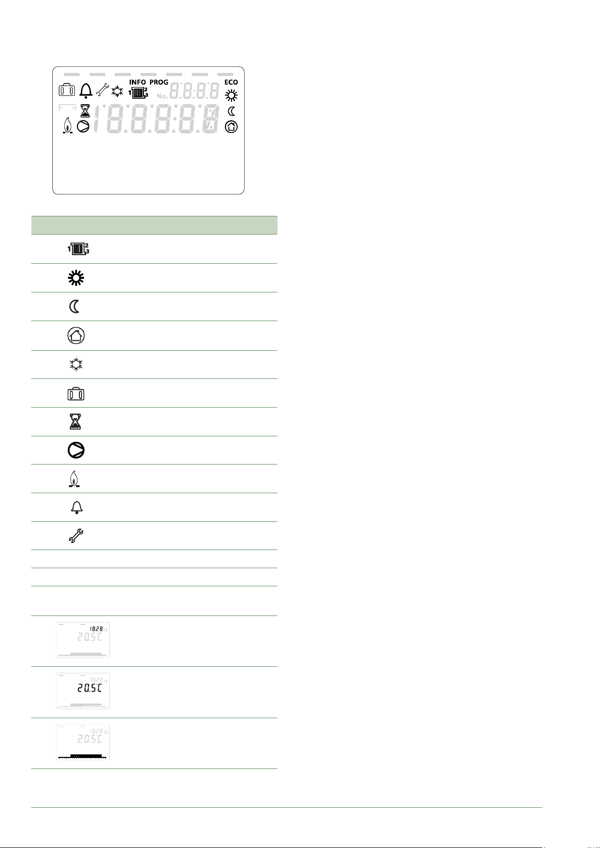
Description of the display
►
Xxxxxxxxxxxxxxxxxxxxxxxxxxx
Xxxxxxxxxxxxxxxxxxxxxxxxxxx
Xxxxxxxxxxxxxxxxxxxxxxxxxxx
Icons Denitions
- Heating mode active with reference
to the heating circuit.
- Heating in comfort mode.
- Heating in reduced mode.
- Heating in "standby" mode
(antifreeze).
- Refresh mode active.
Temperature control
►
The heat pump's operation is subject to the temperature
control.
The heating circuit water temperature setpoint is
adjusted according to the outdoor temperature.
If there are thermostatic valves on the installation,
these must be fully open or set higher than the normal
temperature setpoint.
Setting
▼
During the installation, the temperature control must be
congured to suit the radiators and level of insulation of
the dwelling.
The temperature control graphs (g. 37) refer to a room
temperature setpoint of 20°C.
The temperature control's gradient determines the
impact of variations in the outdoor temperature on
variations in the heating ow temperature.
The steeper the gradient, the more likely a slight
reduction in the outdoor temperature will cause a
signicant increase in the water ow temperature in the
heating circuit.
The temperature control o-set modies the ow
temperature of all graphs, without modifying the gradient
(g. 38).
Corrective actions to take in the case of discomfort are
listed in the table (g. 39).
INFO
PROG
ECO
temperature ambiante
- Holiday function activated.
- Process in progress.
- Compressor operation.
- Burner operation.
- Default message.
- Maintenance, special operation
- Information level activated.
- Programming activated.
- ECO function activated (Heating
stopped temporarily)
- Time /
Parameter number /
Setpoint value.
- 48 -
temperature ambiante
temperature ambiante
- Ambient temperature /
Setpoint value.
- Setpoint information /
Parameter information.
Waterstage / Installation / 2011 - EN
Page 49
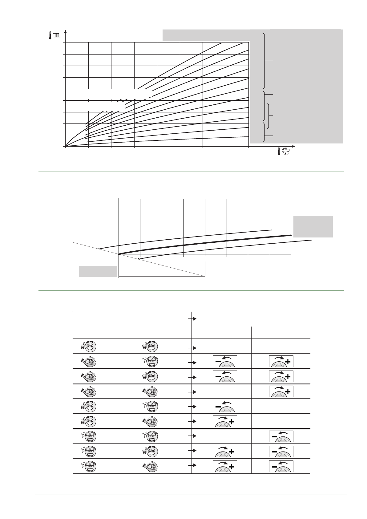
° C
100
90
80
70
With boiler connection
Application relève de chaudière
60
Heat pump application only
Heating ow temperature
Température départ chauffage °C
g. 37 - Heating curve gradient
Application PAC seule
50
40
30
20
30
10
70
60
50
Heating ow
temperature°C
40
30
+4,5
20
Curve o-set
Outdoor temperature
Température extérieure °C
-4,5
10
10
2.753
-100
0
-55
External temperature °C
0
-20
2.5
2.25
2
1.75
1.5
1.25
1
0.75
0.5
0.25
Pente de la
Heating curve gradient
courbe de chauffe
Standard radiator
Radiateur classique
Radiateur BT
Low temperature radiator
(basse température)
Dynamic radiators
Radiateur dynamique
Underoor heating
Plancher chauffant
° C
Heating curve
gradient
0.5
-20-15-10
g. 38 - Transferral of the heating curve
Sensations...
...in mild weather
Good Good
Cold
Cold
Cold Cold
Good
Good
Hot
Hot
Hot
&
&
&
&
&
&
&
&
&
Corrective actions on the temperature control:
...in cold weather Gradient O-set
No correction
No correction
Hot
Good
No correction
Hot
Cold
Hot
No correction
No correction
No correction
Good
Cold
g. 39 - Corrective actions in case of discomfort
Waterstage / Installation / 2011 - EN
- 49 -
Page 50

Controller Menu
OK
General
▼
Only the parameters accessible at the levels:
U - end user.
I - Commissioning
S - Specialist.
are described in this document.
The access levels are specied in the second column of
the table by means of the letters U, I and S.
The OEM parameters are not described and require a
manufacturer access code.
Setting parameters
▼
- Selecting the desired level.
- Scroll the list of menus.
- Selecting the desired menu.
- Scroll the function lines.
- Selecting the desired line.
- Adjusting the parameter.
- Validate the setting by pressing OK.
- To return to the menu, press ESC.
If no setting is made for 8 minutes, the screen
automatically returns to the basic display.
OK
Press and release
Time of day and date Hours / minutes 1 Time 1...24 h
User interface Day/Month 2 Minutes 0...60 min
Heating circuit 1 timer
programme
...
Press for 3
seconds
End user Start-up Specialist OEM
Time of day and date
User interface
Heating circuit 1 timer
programme
...
Recommended settings for the parameters depending on the installation's emitters
▼
End user
OK OK
Year 3
Hours / minutes 1
Day/Month 2
Year 3
End date of summer time 4 01.01...31.12
End date of summer time 5
- 50 -
Heating curve
slope
Curve
displacement
Min.
outgoing value
Max.
initial setpoint
DHW charging
time limitation
Very Low Temperature
Radiators /
Heating-cooling oor
720 (CC1)
1020 (CC2)
721 (CC1)
1021 (CC2)
740 (CC1)
1040 (CC2)
741 (CC1)
1041 (CC2)
5030 Factory (90 min) Factory (90 min) 40 min
0.25 to 0.5 0.5 to 1.25 0.4 to 1.1 1.25 to 3
0 0 4 * 0
Factory (17 °C) Factory (17 °C) 30 or 35 °C
50 °C Factory (55 °C) 65 °C 65 °C
Low temperature
radiators
Dynamic radiators or
fan-coil heaters
Waterstage / Installation / 2011 - EN
Classic
temperature
radiators
Factory
(17 °C)
Factory
(90 min)
Page 51

List of function lines
►
Line Function
Time of day and date
1 U Hours / Minutes 00:00... 23:59 1
2 U Day / Month 01.01... 31.12 1
3 U Year 1900... 2099 1
5 S Start of Summer time (Day / Month) 01.01... 31.12 1 25.03
6 S End of Summer time (Day / Month) 01.01... 31.12 1 25.10
The change of hour will appear at 3:00 rst Sunday after the regulated date.
Operator Section
20 U Language English, Français, Italiano,
22 S Info Temporary, Permanent Temporary
26 S Operation locking On, O O
27 S Programming locking O, On O
28 I Direct setting Automatic storage,
29 I Temperature units
Pressure units
Setting range
or display
Nederlands...
With conrmation
°C, °F
bar, psi
Setting
increment
Basic
setting
English
With
conrmation
°C
bar
44 I Operation HC2 Jointly with HC1
Independently
46 I Operation HC3/P Jointly with HC1
Independently
70 S Display software version
Time program heating / cooling, circuit 1
500 U Pre-selection (Day / Week) Mon-Sun, Mon-Fri, Sat-Sun,
Monday, Tuesday, …
501 U 1st phase On (start) 00:00... --:-- 10 min 6:00
502 U 1st phase O (end) 00:00... --:-- 10 min 22:00
503 U 2nd phase On (start) 00:00... --:-- 10 min --:--
504 U 2nd phase O (end) 00:00... --:-- 10 min --:--
505 U 3rd phase On (start) 00:00... --:-- 10 min --:--
506 U 3rd phase O (end) 00:00... --:-- 10 min --:--
516 U Default values, Circuit 1 No, Yes No
Yes + OK: The default values memorised in the regulator replace and cancel the customised heating programs.
Your customised settings are therefore lost.
Jointly with
HC1
Jointly with
HC1
Mon-Sun
Waterstage / Installation / 2011 - EN
- 51 -
Page 52
Line Function
Time program heating / cooling, circuit 2
Only with the 2nd circuit kit option.
Setting range
or display
Setting
increment
Basic
setting
520 U Pre-selection (Day / Week) Mon-Sun, Mon-Fri, Sat-Sun,
Monday, Tuesday, …
521 U 1st phase On (start) 00:00... --:-- 10 min 6:00
522 U 1st phase O (end) 00:00... --:-- 10 min 22:00
523 U 2nd phase On (start) 00:00... --:-- 10 min --:--
524 U 2nd phase O (end) 00:00... --:-- 10 min --:--
525 U 3rd phase On (start) 00:00... --:-- 10 min --:--
526 U 3rd phase O (end) 00:00... --:-- 10 min --:--
536 U Default values, Circuit 2 No, Yes No
Yes + OK: The default values memorised in the regulator replace and cancel the customised heating programs.
Your customised settings are therefore lost.
Time program 4 / DHW
If the installation is tted with the DHW kit.
560 U Pre-selection (Day / Week) Mon-Sun, Mon-Fri, Sat-Sun,
Monday, Tuesday, …
561 U 1st phase On (start) 00:00... --:-- 10 min 00:00
562 U 1st phase O (end) 00:00... --:-- 10 min 05:00
563 U 2nd phase On (start) 00:00... --:-- 10 min 14:30
564 U 2nd phase O (end) 00:00... --:-- 10 min 17:00
Mon-Sun
Mon-Sun
565 U 3rd phase On (start) 00:00... --:-- 10 min --:--
566 U 3rd phase O (end) 00:00... --:-- 10 min --:--
576 U Default values No, Yes No
Yes + OK: The default values memorised in the regulator replace and cancel the customised heating programs.
Your customised settings are therefore lost.
Holidays, heating circuit 1 (For the Holiday program is active, the heating mode should be on AUTO).
641 U Preselection Period 1 to 8 Period 1
642 U Period Start (Day / Month) 01.01... 31.12 1
643 U Period End (Day / Month) 01.01... 31.12 1
648 U Operating level Frost protection, Reduced Frost
Holidays, heating circuit 2 (For the Holiday program is active, the heating mode should be on AUTO).
If the installation consists of 2 heating circuits (Only with the 2nd circuit kit option).
651 U Preselection Period 1 to 8 Period 1
652 U Period Start (Day / Month) 01.01... 31.12 1
653 U Period End (Day / Month) 01.01... 31.12 1
658 U Operating level Frost protection, Reduced Frost
protection
protection
- 52 -
Waterstage / Installation / 2011 - EN
Page 53
Line Function
Heating adjustment, circuit 1
Setting range
or display
Setting
increment
Basic
setting
710 U Comfort setpoint Reduced setpoint…
Comfort setpoint maximum
712 U Reduced setpoint Frost protection setpoint…
Comfort setpoint
714 U Frost protection setpoint 4 °C… Reduced setpoint 0.5 °C 8 °C
716 S Comfort setpoint maximum 20 °C... 35 °C 1 °C 28 °C
720 I Heating curve slope 0.1... 4 0.02 0.5
(see "Recommended settings for the parameters depending on the installation's emitters", page 50 & g. 37, page 49)
721 I O-set of the heating curve (g. 38, page 49) -4.5 °C... 4.5 °C 0.5 °C 0
730 I Summer / Winter heating limits 8 °C... 30 °C 0.5 °C 18 °C
When the average of the Outdoor temperatures over the past 24 hours reaches 18°C, the regulator switches o the
heating (as an economy measure). During summer mode, the display shows "Eco". This function is only active in
automatic mode.
740 I Flow temp setpoint min 8 °C... Flow temp setpoint max 1 °C 17 °C
(with dynamic radiator, adjust from 30 to 35°C)
741 I Flow temp setpoint max Flow temp setpoint min... 70 °C 1 °C 60 °C
Floor heating system = 50 °C / Radiators = 65 °C.
Important Note : Maximum temperature limitation is not a safety function as required by ground heating.
750 S Room inuence 1%... 100% 1% 50%
0.5 °C 20 °C
0.5 °C 19 °C
If the installation is tted with a room thermostat:
This function enables you to choose the ambient temperature's inuence on the setting.
If no value is entered, the setting is made based on the temperature control.
If the parameter is set at 100%, the setting is only based on the ambient temperature.
760 S Room temperature limitation 0.5... 4 °C 0.5 °C 0.5 °C
As soon as the room temperature = [Setpoint line 710 (ex. 20°C) + Room temperature limitation setpoint line 760
(ex. 0.5 °C)] > 20.5 °C => The heat pump is stopped.
It restarts when the room temperature falls below the setpoint (in the example, Room temperature < 20.0 °C).
780 S Quick setback O, Down to reduced setpoint,
790 S Optimum start control max
(Early start to switch to the comfort setting.)
791 S Optimum stop control max (Early stop to switch
from the comfort setting to the reduced setting.)
800 S Reduced setpoint increase start -30... 10 °C 1 °C --
801 S Reduced setpoint increase end -30... 10 °C 1 °C -5 °C
830 S Mixer valve boost 0... 50 °C 1 °C 0 °C
834 S Actuator running time 30... 873 s 1 s 240 s
Down to frost prot setpoint
0... 360 min 10 min 180 min
0... 360 min 10 min 30 min
O
Waterstage / Installation / 2011 - EN
- 53 -
Page 54
Line Function
850 I Floor curing function (g. 40) O
- O: Early interruption of the current programme, programme inactive.
- Operational heating.
- Heating ready for occupation.
- Operational heating + ready heating.
- Ready heating + operational heating.
- Manual: Manual mode enables you to programme your own concrete slab drying time.The function ends
automatically after 25 days.
Setting range
or display
Setting
increment
Basic
setting
55
50
45
40
35
30
25
20
Heating ow temperature °C
0 1 5 10 18 1
X
Heating ready for occupation
Operational
5 7
heating
1
Operational heating + Heating ready for occupation
g. 40 - Diagram of the concrete slab drying programmes
851 I Floor curing setpoint manually
(if line 850 = manual)
This function enables you to set the custom concrete slab drying temperature. This temperature remains xed.
The concrete slab-drying programme stops automatically after running for 25 days.
856 I Floor curing day current 0... 32
0... 95 °C 1 °C 25 °C
25
Day
Please comply with the
standards and instructions
of the manufacturer of the
building ! A good performance
of this function is only possible
with an installation correctly
implemented (hydraulic,
electricity and adjustments) !
This function can be stopped
by anticipation when setting the
adjustment on "O".
857 I Floor curing day completed 0... 32
900 S Operating mode changeover None, Protection mode,
Reduced, Comfort, Automatic
Operating mode at end of concrete slab drying period
Cooling circuit 1
If the installation is tted with the cooling kit (Only with the cooling kit option).
901 U Operating mode Protection, Automatic, Reduced,
Comfort
902 U Comfort cooling setpoint 17... 40 °C 0,5 °C 24 °C
903 U Reduced setpoint 5... 40°C 26 °C
908 I Flow temp setp at OT° 25°C 6... 35 °C 0,5 °C 20 °C
909 I Flow temp setp at OT° 35°C 6... 35 °C 0,5 °C 16 °C
912 I Cooling limit at OT° 8... 35 °C 0,5 °C 24 °C
913 S Lock time at end of heating / cooling 8... 100 1 h 24 h
918 S Summer comp start at OT° 20... 50 °C 1 °C 26 °C
919 S Summer comp end at OT° 20... 50 °C 1 °C 40 °C
920 S Summer comp setp increase 1... 10 °C 1 °C 4 °C
923 S Flow temp setp min OT° 25°C 6... 35 °C 0.5 °C 18 °C
1 Reduced
Protection
924 S Flow temp setp min OT° 35°C 6... 35 °C 0.5 °C 18 °C
- 54 -
Waterstage / Installation / 2011 - EN
Page 55
Line Function
928 S Room inuence 1... 100 % 1 % 80 %
If the installation is tted with a room thermostat:
This function enables you to choose the ambient temperature's inuence on the setting.
If no value is entered, the setting is made based on the temperature control.
If the parameter is set at 100%, the setting is only based on the ambient temperature.
932 S Room temp limitation 0,5... 4 °C 0,5 °C 0,5 °C
938 S Mixing valve decrease 0... 20 °C 1 °C 0 °C
941 S Actuator running time 30... 873 s 1 s 240 s
963 S With prim contr / system pump No, Yes No*
*Basic setting : 1 circuit = No ; 2 circuits = Yes.
Heating adjustment, Circuit 2
Only with the 2nd circuit kit option (If the installation consists of 2 heating circuits).
Setting range
or display
Setting
increment
Basic
setting
1010 U Comfort setpoint Reduced setpoint…
Comfort setpoint maximum
1012 U Reduced setpoint Frost protection setpoint…
Comfort setpoint
1014 U Frost protection setpoint 4 °C… Reduced setpoint 0.5 °C 8 °C
1016 S Comfort setpoint maximum Comfort temp... 35 °C 1 °C 28 °C
1020 I Heating curve slope 0.1... 4 0.02 0.5
(see "Recommended settings for the parameters depending on the installation's emitters", page 50 & g. 37, page 49)
1021 I O-set of the heating curve (g. 38, page 49) -4.5... 4.5 °C 0.5 °C 0 °C
1030 I Summer / Winter heating limits 8... 30 °C 0.5 °C 18 °C
When the average of the outdoor temperatures over the past 24 hours reaches 18°C, the regulator switches o the
heating (as an economy measure). During summer mode, the display shows "Eco". This function is only active in
automatic mode.
1040 I Flow temp setpoint min 8... 70 °C 1 °C 17 °C
(with dynamic radiator, adjust from 30 to 35°C)
1041 I Flow temp setpoint max 8... 70 °C 1 °C 60 °C
Floor heating system = 50 °C / Radiators = 65 °C.
Important Note : Maximum temperature limitation is not a safety function as required by ground heating.
1050 S Room inuence 1 %... 100 % 1 % 50 %
0.5 °C 20 °C
0.5 °C 19 °C
If the installation is tted with a room thermostat:
This function enables you to choose the ambient temperature's inuence on the setting.
If no value is entered, the setting is made based on the temperature control.
If the parameter is set at 100%, the setting is only based on the ambient temperature.
1060 S Room temperature limitation 0.5... 4 °C 0.5 °C 0.5 °C
As soon as the room temperature = [Setpoint line 1010 (ex. 20°C) + Room temperature limitation setpoint line 1060
(ex. 0,5 °C)] > 20,5 °C => The heat pump is stopped.
It restarts when the room temperature falls below the setpoint (in the example, Room temperature < 20,0 °C).
1080 S Quick setback O, Down to reduced setpoint,
Down to frost prot setpoint
1090 S Optimum start control max 0... 360 min 10 min 180 min
1091 S Optimum stop control max 0... 360 min 10 min 30 min
1100 S Reduced setpoint increase start -30... 10 °C, --°C 1 °C --
1101 S Reduced setpoint increase end -30... 10 °C, --°C 1 °C -5 °C
1130 S Mixer valve increase 0... 50 °C 1 °C 0 °C
1134 S Actuator running time 30... 873 s 1 s 240 s
O
Waterstage / Installation / 2011 - EN
- 55 -
Page 56

Line Function
1150 I Floor curing function (g. 40, page 54) O
- O: Early interruption of the current programme, programme inactive.
- Operational heating.
- Heating ready for occupation.
- Operational heating + ready heating.
- Ready heating + operational heating.
- Manual: Manual mode enables you to programme your own concrete slab drying time.The function ends
automatically after 25 days.
Setting range
or display
Setting
increment
Basic
setting
1151 I Floor curing setpoint manually
(if line 1150 = manual)
This function enables you to set the custom concrete slab drying temperature. This temperature remains xed.
The concrete slab-drying program stops automatically after running for 25 days.
1156 I Floor curing day current 0... 32
1157 I Floor curing day completed 0... 32 0
1200 S Operating mode changeover None, Protection mode,
Operating mode at end of concrete slab drying period.
Cooling circuit 2
If the installation is tted with the cooling kit (Only with the cooling kit option).
1201 U Operating mode Protection, Automatic, Reduced,
1202 U Comfort cooling setpoint 17... 40 °C 0.5 °C 24 °C
1203 U Reduced setpoint 5... 40°C 26 °C
1208 I Flow temp setp at OT° 25°C 6... 35 °C 0.5 °C 20 °C
1209 I Flow temp setp at OT° 35°C 6... 35 °C 0.5 °C 16 °C
1212 I Cooling limit at OT° 8... 35 °C 0.5 °C 24 °C
1213 S Lock time at end of heating / cooling 8... 100 1 h 24 h
0... 95 °C 1 °C 25 °C
Reduced, Comfort, Automatic
Comfort
Reduced
Protection
1218 S Summer comp start at OT° 20... 50 °C 1 °C 26 °C
1219 S Summer comp end at OT° 20... 50 °C 1 °C 40 °C
1220 S Summer comp setp increase 1... 10 °C 1 °C 4 °C
1223 S Flow temp setp min OT° 25°C 6... 35 °C 0.5 °C 18 °C
1224 S Flow temp setp min OT° 35°C 6... 35 °C 0.5 °C 18 °C
1228 S Room inuence 1... 100 % 1 % 80 %
If the installation is tted with a room thermostat:
This function enables you to choose the ambient temperature's inuence on the setting.
If no value is entered, the setting is made based on the temperature control.
If the parameter is set at 100%, the setting is only based on the ambient temperature.
1232 S Room temp limitation 0.5... 4 °C 0.5 °C 0.5 °C
1238 S Mixing valve decrease 0... 20 °C 1 °C 0 °C
1241 S Actuator running time 30... 873 s 1 s 240 s
1263 S With prim contr / system pump No, Yes No*
*Basic setting : 1 circuit = No ; 2 circuits = Yes.
- 56 -
Waterstage / Installation / 2011 - EN
Page 57
Line Function
Domestic hot water
If the installation is tted with the DHW kit.
1600 U Operating mode O, On, Eco On
Setting range
or display
Setting
increment
Basic
setting
1610 U Nominal setpoint Reduced setpoint (line 1612)…
65 °C
The backup electrical system is required to reach this level.
1612 U Reduced setting 8 °C...
Nominal setting (line 1610)
1620 I Release of DHW load 24h / day
Heating circuit time programme
Programme 4 / DHW
O-peak tari (O-peak)
Programme 4 / DHW
and O-peak
24h / day: The temperature of the DHW is constantly maintained at the DHW comfort setting.
Heating circuit time programme: The DHW is produced according to the programming for the ambient temperature
(with 1 hour in advance when switched on).
Programme 4 / DHW: The DHW programme is separate form the heating circuit programme.
O-peak tari* : The electrical backup heating is only authorised to operate during the o-peak period.
T'prog 4/DHW or low-tari *: The electrical backup heating is authorised to operate during the comfort period or o peak.
* - Connect the "Power Provider" contact to input EX2 (see g. 36, page 43). In the case of a day /night contract,
the electric back-ups for the DHW tank are subject to the power supplier's taris. Switching on the electric back-up for
the DHW tank is only authorised during o-peak hours.
1640 I Legionella function O, Periodically (depending line setting 1641),
Fixed weekday (depending line setting 1642)
1 55 °C
1 40 °C
Programme
4 / DHW
O
1641 I Legionella function periodically 1 to 7 1 day 7
1642 S Legionella function weekday Monday, Tuesday,... Saturday
1644 S Legionella funct time
1645 S Legionella funct setpoint
1646 S Legionella funct duration
1647 S Legionella funct circ pump O, On O
1660 S Circulating pump release Time program 3/HCP, DHW release,
Time program 4/DHW, Time program 5
Swimming pool (Only with swimming pool kit option)
2055 U Setpoint solar heating 8... 80 °C 26 °C
2056 U Setpoint source heating 8... 35 °C 22 °C
2057 S Swi di source heating 0.5... 3 °C 0.5 °C
2065 S Charging priority solar Priority 1, Priority 2, Priority 3 Priority 1
2080 S With solar integration No, Yes Yes
DHW release
Waterstage / Installation / 2011 - EN
- 57 -
Page 58
Line Function
Heat pump (HP)
2803 S Overrun time cond pump 8... 240 s 1 s 240s
2843 S Compressor o time min 0... 120 min 1 min 8 min
2844 S Switch-o temp max 8... 100 °C 1 °C 75 °C
2862 S Locking time stage 2 / mod 0... 40 min 1 min 5 min
2873 S Compressor mod run time 10... 600 s 1 s 240 s
2882 S Release integr electric ow 0... 500 °Cmin 1 °Cmin 100 °Cmin
Setting range
or display
Setting
increment
Basic
setting
2884 S Release el ow below OT
2899 I Min ow switch consumers 1...1200 l/h 1 l/h 600 l/h
2916 S Max setpoint HP DHW charg 8... 80 °C 60 °C
2920 S With electrical utility lock (EX1) Locked (Blocked on standby),
Energy meter
3095 --> 3110 : Not used
3113 U Energy brought in Kwh --
3121 --> 3123 : Not used
3124 U Energy brought in heating 1 (N - 1) Kwh --
3125 U Energy brought in DHW 1 Kwh --
3126 U Energy brought in cooling 1 Kwh --
Electrical release - start-up with outdoor
temperature
Released : HP = ON _ Back-up DHW = o _ 1st back-up HP = o _ 2nd back-up HP = o _ Boiler = ON
Locked (Blocked on standby) : HP = o _ Back-up DHW = o _ 1st back-up HP = o _ 2nd back-up HP = o _
Boiler = ON
Cumulation of total consumed electrical energy.
Electrical energy consumed = Electrical energy absorbed by outdoor unit + electric energy absorbed by the heating
electrical backup and / or DHW electrical backup (if installed).
-30... 30 °C 2 °C
Released
Released
3128 --> 3130 : Not used
3131 U Energy brought in heating 2 (N - 2) Kwh --
3132 U Energy brought in DHW 2 Kwh --
3133 U Energy brought in cooling 2 Kwh --
3135 --> 3137 : Not used
3138 U Energy brought in heating 3 (N - 3) Kwh --
3139 U Energy brought in DHW 3 Kwh --
3140 U Energy brought in cooling 3 Kwh --
3142 --> 3144 : Not used
3145 U Energy brought in heating 4 (N - 4) Kwh --
3146 U Energy brought in DHW 4 Kwh --
3147 U Energy brought in cooling 4 Kwh --
3149 --> 3151 : Not used
3152 U Energy brought in heating 5 (N - 5) Kwh --
3153 U Energy brought in DHW 5 Kwh --
3154 U Energy brought in cooling 5 Kwh --
- 58 -
Waterstage / Installation / 2011 - EN
Page 59
Line Function
3156 --> 3158 : Not used
3159 U Energy brought in heating 6 (N - 6) Kwh --
3160 U Energy brought in DHW 6 Kwh --
3161 U Energy brought in cooling 6 Kwh --
3163 --> 3165 : Not used
3166 U Energy brought in heating 7 (N - 7) Kwh --
3167 U Energy brought in DHW 7 Kwh --
3168 U Energy brought in cooling 7 Kwh --
3170 --> 3172 : Not used
3173 U Energy brought in heating 8 (N - 8) Kwh --
3174 U Energy brought in DHW 8 Kwh --
3175 U Energy brought in cooling 8 Kwh --
3177 --> 3179 : Not used
3180 U Energy brought in heating 9 (N - 9) Kwh --
3181 U Energy brought in DHW 9 Kwh --
Setting range
or display
Setting
increment
Basic
setting
3182 U Energy brought in cooling 9 Kwh --
3184 --> 3186 : Not used
3187 U Energy brought in heating 10 (N - 10) Kwh --
3188 U Energy brought in DHW 10 Kwh --
3189 U Energy brought in cooling 10 Kwh --
3190 S Reset xed day storage No, Yes No
Reset the historical counters (1 to 10). The general counter (parameter 3113) is not reset.
3197 S Compressor electrical power 0.1...60 0.1 See table
below
Set the parameter 3197 according to the outdoor unit
Heat Pump Outdoor unit Parameter 3197
Waterstage SHP 16
Waterstage SHP TRI 15
Waterstage SHP TRI 17
3264 --> 3267 : Not used
WOYG160LJL 5.37
WOYK150LJL 4.55
WOYK170LJL 5.32
Note: "Energy" Counters increment as of 1 July each year.
Waterstage / Installation / 2011 - EN
- 59 -
Page 60
Line Function
Additional generator (Boiler connection)
Setting range
or display
Setting
increment
Basic
setting
3692 S With DHW charging Locked, Substitute,
Complement, Instantly
- DHW Instantly : When DHW request, the HP and the boiler are put into operation. The HP will stop when the primary
return temperature is over 55 °C.
- DHW Substitute : If the outdoor temperature is above 2 °C, the operation of the HP when DHW request last 5 minutes
at least. The HP operating time can be extended depending on the outdoor temperature. The boiler will activate then.
3700 S Release below outdoor temperature -50... 50 °C 1 °C 2 °C
3701 S Release above outdoor temperature -50... 50 °C 1 °C --
3705 S Overrun time 0... 120 min 1 min 20 min
3720 S Switching integral (for boiler relief) 0... 500 °Cmin 1 °Cmin 100 °Cmin
3723 S Locking time 1... 120 min 1 min 30 min
Domestic hot water (DHW)
If the installation is tted with the DHW kit.
5024 S Switching di 0... 20 °C 1 °C 7 °C
5030 S Charging time limitation 10... 600 min 10 min 90 min
(with dynamic radiator, adjust 40 min)
5055 S Recooling temp 10... 95 °C 1 °C 65 °C
5057 S Recooling collector O, Summer, Always Summer
5061 S Electric immersion heater release 24h / day, Release of DHW,
Programme 4 / DHW
Substitute
Release of
DHW
5093 S With solar integration No, Yes Yes
Installation conguration
5700 I Pre-setting 1,2,3,... 9 1 1
This control enables you to choose one of the 4 pre-selected installation congurations. The hydraulic layouts for the
various congurations are detailed in the section: "Installation Congurations".
- Pre-setting 1: 1 heating circuit with or without electrical back-up, with DHW tank.
- Pre-setting 2: 2 heating circuits with or without electrical back-up, with DHW tank.
- Pre-setting 3: Boiler connection and 1 heating circuit and DHW tank.
- Pre-setting 4: Boiler connection and 2 heating circuits and DHW tank.
- Pre-setting 5 and more: Not used.
5710 S Heating circuit 1 O, On On
5711 S Cooling circuit 1 O, 4-pipe system cooling,
2-pipe system cooling
Set the parameter to "2-pipe system cooling" with the cooling kit.
5715 S Heating circuit 2 O, On On
5716 S Cooling circuit 2 O, 4-pipe system cooling,
2-pipe system cooling
Set the parameter to "2-pipe system cooling" with the cooling kit.
If the installation consists of 2 heating circuits.
5731 S DHW controlling element Q3 No charging request,
Charging pump,
Diverting valve
O
O
Diverting
valve
5740 S Output el imm heater K6 0,1... 99 kW 2
5740 = Value of the DHW electrical backup - kW
5806 I Type el imm heater ow 1 : 3-stage, 2 : 2-stage excluding,
5811 S Output el imm heater K25 0,1-...99 3
Without electrical backup = 0 ; Single phase electrical backup (Factory setting) = 3 ; 3-phase electrical backup = 9
- 60 -
3 : 2-stage complementary,
4 : Modulating UX
2-stage
complementary
Waterstage / Installation / 2011 - EN
3 :
Page 61
Line Function
5813 S Output el imm heater K26 0,1-...99 3
Without electrical backup = 0 ; Single phase electrical backup 3 kW = 0 ;
Single phase electrical backup 6 kW (Factory setting) = 3 ; 3-phase electrical backup = 0
5950 S Function input H1 (Connector X86, terminals B1 & M) None
0: None, 1: Op'mode change zones+DHW, 2: Optg mode changeover DHW, 3: Op'mode changeover zones,
4: Op'mode changeover zone 1, 5: Op'mode changeover zone 2, 6: Op'mode changeover zone 3,
8: Error/alarm message, 9: Consumer request VK1, 10: Consumer request VK2, 11: Release swi pool source heat,
13: Release swi pool solar, 14: Operating level DHW, 15: Operating level HC1, 16: Operating level HC2,
17: Operating level HC3, 18: Room thermostat HC1, 19: Room thermostat HC2, 20: Room thermostat HC3,
21: DHW ow switch, 24: Pulse count, 26: Dewpoint monitor, 27: Flow temp setp incr hygro, 30: Swi-on command HP stage 1,
35: Status info suppl source, 36: Charg prio DHW sol fuel boil, 43: Ventilation switch 1, 44: Ventilation switch 2,
45: Ventilation switch 3, 50: Flow measurement Hz, 51: Consumer request VK1 10V, 52: Consumer request VK2 10V,
54: Pressure measurement 10V, 55: Humidity measurement 10V, 56: Room temp 10V, 59: Flow measurement 10V,
60: Temp measurement 10V, 61: Air quality measurement 10V
5953 S Input value 1 H1 0
5954 S Function value 1 H1 0
5955 S Input value 2 H1 10
5956 S Function value 2 H1 100
5960 S Function input H3 (Connector X86, terminals B2 & M) None
0: None, 1: Op'mode change zones+DHW, 2: Optg mode changeover DHW, 3: Op'mode changeover zones,
4: Op'mode changeover zone 1, 5: Op'mode changeover zone 2, 6: Op'mode changeover zone 3,
8: Error/alarm message, 9: Consumer request VK1, 10: Consumer request VK2, 11: Release swi pool source heat,
13: Release swi pool solar, 14: Operating level DHW, 15: Operating level HC1, 16: Operating level HC2,
17: Operating level HC3, 18: Room thermostat HC1, 19: Room thermostat HC2, 20: Room thermostat HC3,
21: DHW ow switch, 24: Pulse count, 26: Dewpoint monitor, 27: Flow temp setp incr hygro, 30: Swi-on command HP stage 1,
35: Status info suppl source, 36: Charg prio DHW sol fuel boil, 43: Ventilation switch 1, 44: Ventilation switch 2,
45: Ventilation switch 3, 50: Flow measurement Hz, 51: Consumer request VK1 10V, 52: Consumer request VK2 10V,
54: Pressure measurement 10V, 55: Humidity measurement 10V, 56: Room temp 10V, 59: Flow measurement 10V,
60: Temp measurement 10V, 61: Air quality measurement 10V
Setting range
or display
Setting
increment
Basic
setting
5963 S Input value 1 H3 0
5964 S Function value 1 H3 0
5965 S Input value 2 H3 10
5966 S Function value 2 H3 100
5980 S Function input EX1 Electrical
0: None, 1: Electrical utility lock E6, 2: Low-tari E5, 4: Overload source E14, 5: Pressure switch source E26,
6: Flow switch source E15, 7: Flow switch consumers E24, 8: Manual defrost E17, 9: Common fault HP E20,
10: Fault soft starter E25, 12: Low-pressure switch E9, 13: High-pressure switch E10, 14: Overload compressor 1 E11,
15: Error/alarm message, 16: Mains supervision E21, 18: Pressure di defrost E28, 19: Pres sw source int circ E29,
20: Flow sw source int circ E30, 21: Smart grid E61, 22: Smart grid E62, 25: Optg mode change HCs, 26: DHW push.
5981 S Contact type input EX1 Normally-closed contact (NC)
Normally-opened contact (NO)
5982 S Function input EX2 Low-tari E5
0: None, 1: Electrical utility lock E6, 2: Low-tari E5, 4: Overload source E14, 5: Pressure switch source E26,
6: Flow switch source E15, 7: Flow switch consumers E24, 8: Manual defrost E17, 9: Common fault HP E20,
10: Fault soft starter E25, 12: Low-pressure switch E9, 13: High-pressure switch E10, 14: Overload compressor 1 E11,
15: Error/alarm message, 16: Mains supervision E21, 18: Pressure di defrost E28, 19: Pres sw source int circ E29,
20: Flow sw source int circ E30, 21: Smart grid E61, 22: Smart grid E62, 25: Optg mode change HCs, 26: DHW push.
5983 S Contact type input EX2 Normally-closed contact (NC)
Normally-opened contact (NO)
5985 S Contact type input EX3 Normally-closed contact (NC)
Normally-opened contact (NO)
utility lock E6
NO
NC
NO
6098 S Readjustm collector sensor -20... 20 0
6100 S Readjustm outdoor sensor -3... 3 °C 0.1 °C 0 °C
6117 S Central setp compensation 1... 100°C 5 °C
6120 S Frost protection plant On, O On
Waterstage / Installation / 2011 - EN
- 61 -
Page 62

Line Function
6201 S Reset sensors No, Yes No
6205 S Reset to default parameters No, Yes No
6220 S Software version (RVS) 0... 99 --
6300 S Info 1 OEM 0... 65535 --
6301 S Info 2 OEM 0... 65535 --
LPB system
6600 S Device address 0... 16 1
Error
6710 U Reset Defaut relais No, Yes No
6711 U Reset HP No, Yes No
6800 S History 1 Time, Date, Error code
6802 S History 2 Time, Date, Error code
6804 S History 3 Time, Date, Error code
6806 S History 4 Time, Date, Error code
6808 S History 5 Time, Date, Error code
Setting range
or display
Setting
increment
Basic
setting
6810 S History 6 Time, Date, Error code
6812 S History 7 Time, Date, Error code
6814 S History 8 Time, Date, Error code
6816 S History 9 Time, Date, Error code
6818 S History 10 Time, Date, Error code
Maintenance / special regime
7070 S HP interval --, 1... 240 1 month --
7071 S HP time since maint
Reset ? (no, yes)
7073 S Cur starts compr1/hrs run (since the 6 last weeks)
Reset ? (no, yes)
7141 U Emergency operation O, On O
O: Heat pump functions normally (with boosters if necessary).
On: Heat pump uses the electric boost system or the boiler connection.
Use the “On” position only in Assist mode or Test mode: may result in high power bills.
7142 S Emergency operating function type Manual, Automatic Manual
Manual: Emergency mode is not active when a fault occurs (Emergency mode = OFF).
Automatic: Emergency mode is active when a fault occurs (Emergency mode = ON).
In "Automatic" position, the energy cost can be onerous if the error is not detected and eliminated.
7150 I Simulation outdoor temp -50... 50 °C 0.5 --
0... 240 1 month 0
0... 12 0
- 62 -
Waterstage / Installation / 2011 - EN
Page 63
Line Function
Inputs / outputs test
7700 I Relay test No test
This consists of instructing the regulator's relays one by one and checking their outputs. This enables you to check that
the relays are working and that the cabling is correct. Check that each appliance in the installation is operating correctly.
0: No test, 1: Everything is on STOP, 2: Relay output QX1 : heat pump CC1 (if 1 circuit ) or heat pump CC2 (if 2 circuits),
3: Relay output QX2 : Electrical back-up (1st stage) or Boiler connection distribution valve,
4: Relay output QX3 : Electrical back-up (2nd stage) or Boiler connection contact,
5: Relay output QX4 : DHW distribution valve, 6: Relay output QX5 : DHW Electrical back-up, 7: Relay output QX6 ,
8: Relay output QX31 : Heat circ mix valve open Y1 (or control pilot-wire), 9: Relay output QX32 : Heat circ mix valve close Y2,
10: Relay output QX33 : heat pump CC1 if 2 circuits (mixed circuit, the less hot), 11: Relay output QX34,
12: Relay output QX35 : Swimming pool distribution valve, 13: Relay output QX21 module 1, 14: Relay output QX22 module 1,
15: Relay output QX23 module 1, 16: Relay output QX21 module 2, 17: Relay output QX22 module 2,
18: Relay output QX23 module 2, 19: Not used, 20: Not used, 21: Not used.
The display shows the “Key” symbol. Pressing the Info button displays "Error 368".
Warning: The component being tested is receiving electrical power throughout the test.
7710 I Output UX1 test 0... 100% 1 --
7716 I Output UX2 test 0... 100% 1 --
7722 I Digital output DO2 O, On O
7723 I Heat pump D3 O, On O
7724 I Outputs test UX3 ("Inverter" command) 0... 100 % --
7725 I Voltage value U4 (Ux3) 0... 10 v --
Setting range
or display
Setting
increment
Basic
setting
7804 I Sensor temperature BX1 (HP ow temperature) -28... 350 °C --
7805 I Sensor temperature BX2 (HP return temperature) -28... 350 °C --
7806 I Sensor temperature BX3 (DHW temperature) -28... 350 °C --
7807 I Sensor temperature BX4 (Outdoor temperature) -28... 350 °C --
7858 I Input signal H3
7911 I Input EX1 (Power shedding, EJP) 0, 230 V --
7912 I Input EX2 (Taris day/night) 0, 230 V --
7913 I Input EX3 (External fault) 0, 230 V --
State
8000 I State heating circuit 1 --
8001 I State heating circuit 2 --
8003 I State DHW --
8004 I State cooling circuit 1 --
8006 I State heat pump --
8007 I State solar --
8010 I State buer --
8011 I State swimming pool --
None, Closed (ooo), Open (---)
Pulse, Frequency Hz, Voltage V
,
None
8022 I State supplementary source --
8025 I State cooling circuit 2 --
Waterstage / Installation / 2011 - EN
- 63 -
Page 64
Line Function
Generator diagnosis
8400 I Compressor 1 O, On O
8402 I Electrical resistance ow 1 O, On O
8403 I Electrical resistance ow 2 O, On O
8406 I Condenser pump O, On O
8407 S Speed condenser pump 0...100% --
8410 U Return temp HP 0... 140 °C --
Setpoint (ow) HP --
8412 U Flow temp HP 0... 140 °C --
Setpoint (ow) HP --
8413 U Compressor modulation 0... 100% --
8414 I Modulation electric ow 0... 100% --
8425 S Temp di condensor -50... 140 °C --
8450 S Hours run compressor 1 00:00 --
Setting range
or display
Setting
increment
Basic
setting
8454 S Locking time Heat Pump
Reset ? (no, yes)
8455 S Counter number of locks HP
Reset ? (no, yes)
8456 S Hours run electrical ow
Reset ? (no, yes)
8457 S Start counter electrical ow
Reset ? (no, yes)
8458 I State smart grid Draw disabled, Draw free,
8460 I Heat pump throughput 0... 65535 l/min --
Diagnostics consumers
8700 U Outdoor temperature -50... 50 °C --
8701 U Outdoor temp min
Reset ? (no, yes)
8702 U Outdoor temp max
Reset ? (no, yes)
8703 I Outdoor temp attenuated
Reset ? (no, yes)
This is the average of the outdoor temperature over a 24-hour period.
This value is used for automatic Summer / Winter switchover (line 730).
0... 2730 h --
0... 65535 --
0... 2730 h --
0... 65535 --
Draw wish, Draw forced
-50... 50 °C 50 °C
-50... 50 °C -50 °C
-50... 50 °C --
Draw free
8704 I Outdoor temp composite -50... 50 °C --
The mixed outdoor temperature is a combination of the current outdoor temperature and the average outdoor temperature
calculated by the regulator. This value is used for calculating the initial temperature.
8730 I Heating circuit pump, circuit 1 O, On O
8731 I Mixer valve HC1 open O, On O
8732 I Mixer valve HC1 closed O, On O
8740 U Room temperature 1 0... 50 °C --
Room setting 1 20 °C
8743 U Flow temperature 1 0... 140 °C --
Flow temperature setpoint 1 --
8749 I Room thermostat 1 No demand, Demand No demand
- 64 -
Waterstage / Installation / 2011 - EN
Page 65

Line Function
8756 U Cooling ow temperature 1 0... 140 °C --
Cooling ow temperature setpoint 1 --
8820 I DHW pump O, On O
8821 I El imm heater DHW O, On O
8830 U DHW (domestic hot water) temperature 0... 140 °C --
DHW temperature setpoint 50 °C
8832 I DHW temp 2 0... 140 °C --
8840 S Hours run DHW pump 0... 2730 h --
8841 S Start counter DHW pump 0... 199999 --
8842 S Hours run electric DHW 0... 2730 h --
8843 S Start counter electric DHW 0... 65535 --
8950 I Common ow temperature 0... 140 °C --
Common ow temperature setpoint --
8957 I Common ow setpoint, Refrigerant 0... 140 °C --
9005 I Water pressure 1 -100... 500 bar --
Setting range
or display
Setting
increment
Basic
setting
9006 I Water pressure 2 -100... 500 bar --
9009 I Water pressure 3 -100... 500 bar --
9010 I Measurement room temp 1 0...50 °C --
9011 I Measurement room temp 2 0... 50 °C --
9031 I Relay output QX1 O, On On
9032 I Relay output QX2 O, On On
9033 I Relay output QX3 O, On On
9034 I Relay output QX4 O, On O
9035 I Relay output QX5 O, On O
Waterstage / Installation / 2011 - EN
- 65 -
Page 66
Information display
►
Various data can be displayed by pressing the
button.
Depending on the type of unit, conguration and
operating state, some of the info lines listed below may
not appear.
- Possible error messages from the error code list
(see table, page 74).
- Possible service messages from the maintenance
code list.
- Possible special mode messages.
- Various data (see below).
Designation Line
Floor drying current setpoint. -
Current drying day. -
Terminated drying days. -
State heat pump. 8006
State supplementary source. 8022
State DHW. 8003
State swimming pool. 8011
State heating circuit 1. 8000
State heating circuit 2. 8001
State cooling circuit 1. 8004
Outdoor temperature. 8700
Room temperature 1.
Room setpoint 1.
Flow temperature 1.
Flow temperature setpoint1.
Room temperature 2.
Room setpoint 2.
Flow temperature 2.
Flow temperature setpoint 2.
DHW (domestic hot water) temperature. 8830
Heat pump return temperature.
Setpoint (return) HP.
Heat pump ow temperature.
Setpoint (ow) HP.
Swimming pool temperature.
Swimming pool temperature setpoint.
Minimum remaining stop time for compressor 1. -
Minimum remaining running time for compressor 1. -
8740
8743
8770
8773
8410
8412
8900
- 66 -
Waterstage / Installation / 2011 - EN
Page 67

Page 68
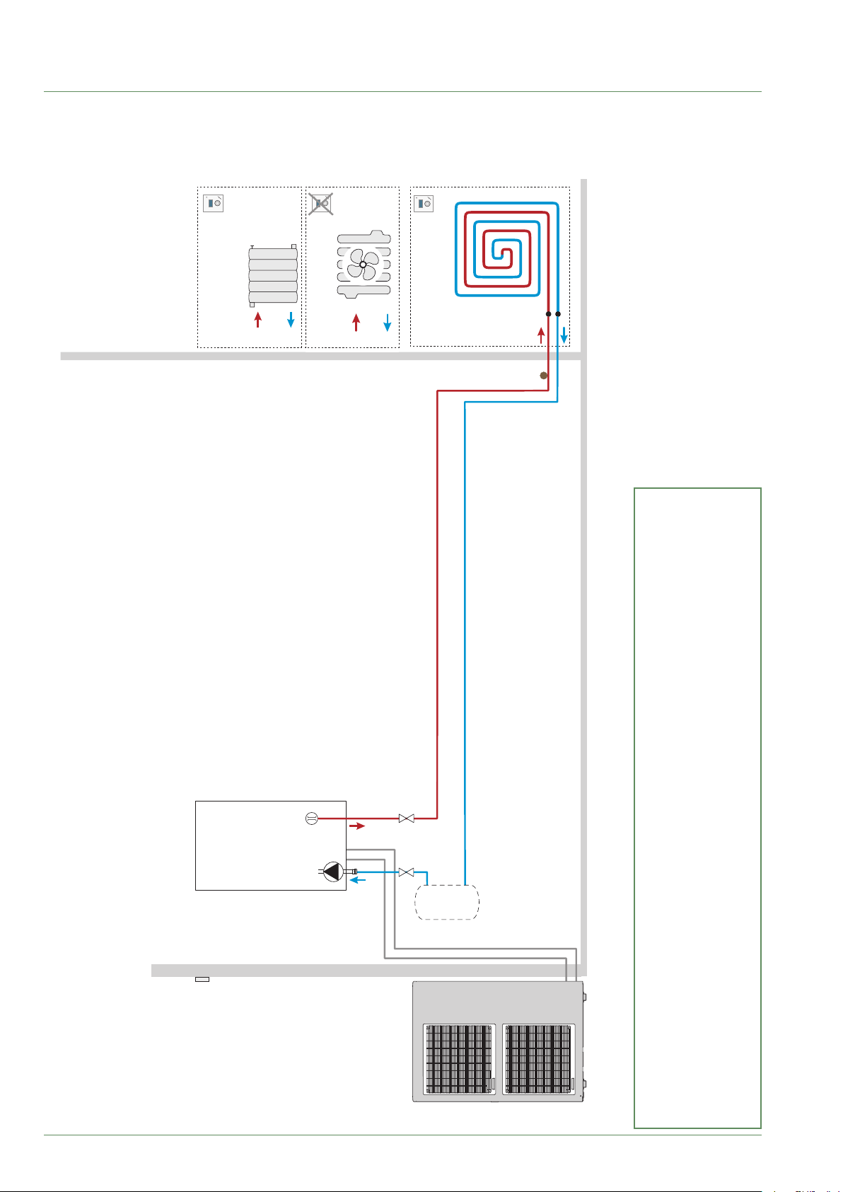
Basic Hydraulic Layout
■ Conguration: 1 heating circuit
SA
OU
R
SA*
Rdyn*
OU
SA
PC
SP
- 68 -
MH
SE
Db
CC
PC - Underoor heating system
R - Radiator
Rdyn* - Dynamic radiator
SA* - Room sensor (option/ except with Rdyn)
SE - Outside sensor
SP - Heated oor thermal safety fuse
BT*
Key:
Waterstage / Installation / 2011 - EN
BT* - Buer tank (obligatory with Rdyn)
CC - Heating circulation pump
Db - Flowmeter
MH - Hydraulic unit
Page 69
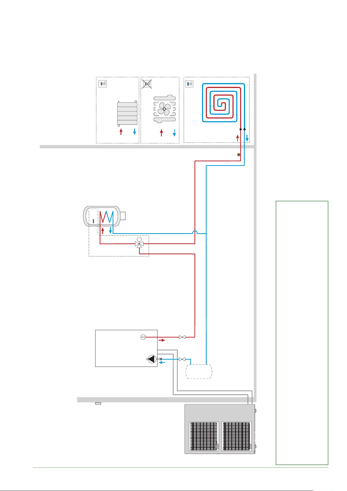
■ Conguration: 1 heating circuit and mixed hot water tank
Ssa
KS
SA
AE
OU
R
A
AB
SA*
M
B
VD
Rdyn*
OU
SA
PC
SP
MH
SE
Waterstage / Installation / 2011 - EN
Db
CC
PC - Underoor heating system
R - Radiator
Rdyn* - Dynamic radiator
SA* - Room sensor (option/ except with Rdyn)
SSa - Hot water sensor
SE - Outside sensor
SP - Heated oor thermal safety fuse
VD - Distribution valve
BT*
Key:
AE - Electrical backup
BT* - Buer tank (obligatory with Rdyn, if HP>11kW)
CC - Heating circulation pump
Db - Flowmeter
KS - DHW kit
MH - Hydraulic unit
- 69 -
Page 70
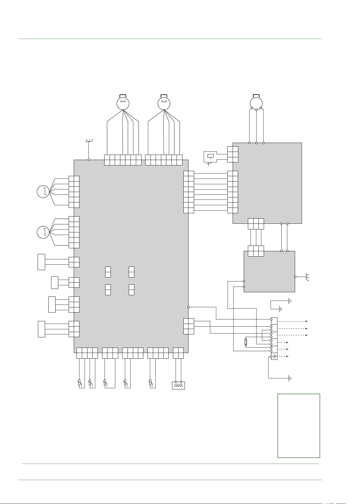
Electrical Cabling Plans
Valve
BOBINE
Coil 2 (inj.)
Expansion
(INJECTION)
DETENDEUR 2
Valve
Coil 1
BOBINE
Expansion
DETENDEUR 1
Coil
Valve
VANNE
BOBINE
ELECTRO
Solenoid
4-way
Pressure
PRESSOSTAT
(HAUTE
(High)
Sensor
PRESSION)
Pressure
PRESSOSTAT
M M
SV
Coil
Valve
VANNE
BOBINE
4 VOIES
(BASSE
(Low)
Sensor
PRESSION)
PS
PS
4WV
WH
6
6
YE
5
5
4
4
OR
BU
RD
1 2 3
1 2 3
WH
6
6
YE
4
OR
BU
RD
1 2 3
1 2 3
BU
BU
1 2 5
1 2 5
BU
BU
1 2 4
1 2
BK
WH
1 2 3
1 2 3
RD
BK
WH
2 3
RD
1 2 3
1
BKBKBKBKBK
GN
RD
1
1
M
BK
234
234
(HAUT)
MOTEUR
VENTILATEUR 1
Fan motor 1 (upper)
WHYEBN
RD
567
567
E100
EXT.
EXT.
IN. 2
IN. 1
1 2 1 2
EXT.
EXT.
CN131 CN132
OUT. 2
1 2 1 2
OUT. 1
CN136 CN137
CN119 CN106 CN108 CN116 CN117
CN118
CN146CN144CN147CN142
1 1
234
234
231
231
1
1
BKBKBK
234
234
1
1
1
1
BK
234
234
Main
234
234
BK
M
BK
CARTE PRINCIPALE
(BAS)
MOTEUR
VENTILATEUR 2
Fan motor 2 (lower)
WHYEBN
567
567
CN122 CN104
8
7
6
5
4
1 2 3
DE REGULATION
control board
W006
CN100 CN126
1 2 3
CN139
2
1
2
1
WH
WH
CAPTEUR
Pressure
8
7
6
5
4
1 2 3
RD
1 2 3
P
PRESSION
Switch
BK
WH
WH
WH
GR
VT
BU
GN
YE
OR
RD
BN
1 2 3
8
7
6
5
4
1 2 3
1 2 3
8
7
6
5
4
CN150 CN20
1 2 3
WH
BK
Fuses
FUSIBLE
W(C)
BKWHRD
TM402
WH
20A250V
3~
MS
V(S)
TM401
231
231
RD
231
231
TM502
TM501
BK
BK
U(R)
CN100
BK
CN501
COMPRESSEUR
Compressor
TM400
CARTE
INVERTER
(Inverter)
Control board
TM100
BK
TM507
FILTRE
CARTE
Filter Board
1 2 3L N
BU
Terminal
BORNIER
TM101
WH
TM508
GN
W503
230 V
supply
L + N ~ 50Hz
Electricity
ELECTRIQUE
ALIMENTATION
MODULE
HYDRAULIQUE
Hydraulic unit
230V
(REFOULEMENT)
(COMPRESSEUR)
SONDE TEMPERATURE
SONDE TEMPERATURE
(EXTERIEURE)
SONDE TEMPERATURE
(TUYAUTERIE)
SONDE TEMPERATURE
Temperature sensor. Pi pe
Temperature sensor. Di sch arg e
Temperature sensor. Outd oor
Temperature sensor. C omp res sor
g. 41 - Outdoor unit electrical cabling single phase
- 70 -
(EVAPORATEUR)
SONDE TEMPERATURE
Temperature sensor. Ev apo rat or
Reactor
REACTANCE
Colour codes
BK Black
BN Brown
BU Blue
GN Green
GY Grey
OG Orange
RD Red
VT Violet
WH White
YE Yellow
Waterstage / Installation / 2011 - EN
Page 71
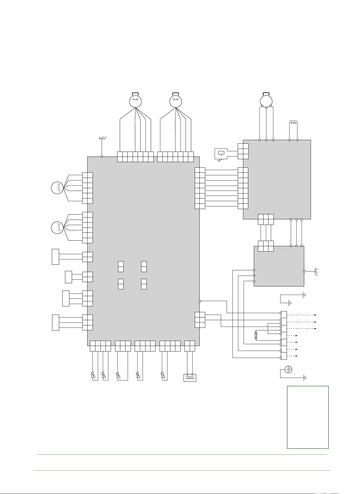
M
(HAUT)
MOTEUR
VENTILATEUR 1
Fan motor 1 (upper)
M
(BAS)
MOTEUR
VENTILATEUR 2
Fan motor 2 (lower)
3~
MS
COMPRESSEUR
Compressor
REACTANCE
Reactor
Valve
BOBINE
Coil 2 (inj.)
Expansion
(INJECTION)
DETENDEUR 2
Valve
Coil 1
BOBINE
Expansion
DETENDEUR 1
Coil
Valve
VANNE
BOBINE
ELECTRO
Solenoid
Pressure
(HAUTE
(High)
Sensor
PRESSION)
Pressure
PRESSOSTAT
M M
SV
Valve
4-way
BOBINE
(BASSE
Sensor
PRESSOSTAT
PS
4WV
Coil
VANNE
4 VOIES
PS
(Low)
PRESSION)
WH
6
6
YE
5
5
4
4
OR
BU
RD
1 2 3
1 2 3
WH
6
6
YE
4
OR
BU
RD
1 2 3
1 2 3
BU
BU
1 2 5
1 2 5
BU
BU
1 2 4
1 2
BK
WH
1 2 3
1 2 3
RD
BK
WH
2 3
RD
1 2 3
1
1 1
BKBKBKBKBK
GN
RD
1
1
234
234
BK
WHYEBN
567
567
RD
1
1
E100
EXT.
EXT.
IN. 2
IN. 1
1 2 1 2
EXT.
EXT.
CN131 CN132
OUT. 2
1 2 1 2
OUT. 1
CN136 CN137
CN119 CN106 CN108 CN116 CN117
CN118
CN146CN144CN147CN142
234
234
231
231
1
1
BKBKBK
234
234
BK
WHYEBN
BK
234
234
Main
DE REGULATION
control board
CARTE PRINCIPALE
234
1
234
1
BK
567
567
CN122 CN104
1
1
WH
CN100 CN126
CN139
2
2
WH
8
7
6
5
4
1 2 3
W006
1 2 3
CAPTEUR
Pressure
8
7
6
5
4
1 2 3
RD
1 2 3
P
PRESSION
Switch
BK
WH
WH
WH
GR
VT
BU
GN
YE
OR
RD
BN
1 2 3
8
7
6
5
4
1 2 3
1 2 3
8
7
6
5
4
CN801 CN805
1 2 3
RD
WH
BK
Fuses
20A250V
FUSIBLE
BKWHRD
TM821
TM819
CN802
231
231
BK
RD
WH
231
231
CN501
TM803
TM802
TM801
BK
BK
RD
TM817
TM812
CARTE
INVERTER
(Inverter)
Control board
TM800
RD
W514
FILTRE
CARTE
Filter Board
1 2 3L1 L2 L3 N
BU
RD
TM814
TM801
BK
WH
W515
Electricity
TM802
W516
GN
W507
supply
3 phase
3L + N ~ 50Hz
ELECTRIQUE
ALIMENTATION
MODULE
HYDRAULIQUE
Hydraulic unit
400V
400 V
(REFOULEMENT)
SONDE TEMPERATURE
SONDE TEMPERATURE
Temperature sensor. Di sch arg e
(EXTERIEURE)
(COMPRESSEUR)
SONDE TEMPERATURE
Temperature sensor. Outd oor
SONDE TEMPERATURE
Temperature sensor. C omp res sor
g. 42 - Outdoor unit electrical cabling 3-phase
Waterstage / Installation / 2011 - EN
(TUYAUTERIE)
Temperature sensor. Pi pe
(EVAPORATEUR)
SONDE TEMPERATURE
Temperature sensor. Ev apo rat or
Reactor
REACTANCE
Terminal
BORNIER
Colour codes
BK Black
BN Brown
BU Blue
GN Green
GY Grey
OG Orange
RD Red
VT Violet
WH White
YE Yellow
- 71 -
Page 72
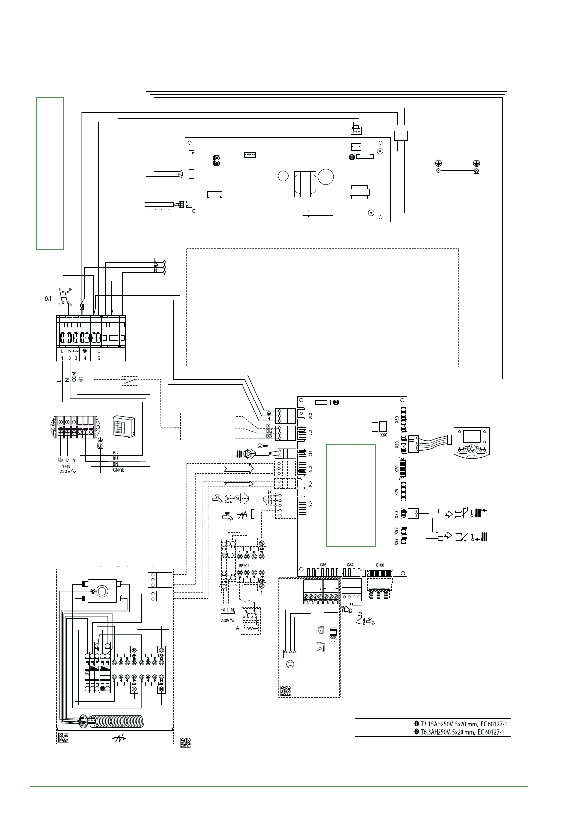
CN21
Option Appoint électrique monophasé
Electric back-up Single phase Option
Débitmètre / Flowmeter (SHP)
CN1
FUSE 250V/3.15A
relay (see g. 34, page 40).
Condensation
sensor
Connection to terminal blocks and power
External
component contact
L N
1 2 3
Power limitation
Taris (day/night)
External faults
CN18
2 circuit option
FUSE 250V/6.3A
B1 B2
A1 A2
( ) 3KW
L
L
(=) 6KW
N
00124534-4-B
Single phase electrical backup
g. 43 - Electrical cabling of single phase hydraulic unit (excluding connections made by installer)
Flow
sensor
Connections on the
(see g. 36, page 43).
heat pump controller,
accessories and options
3 2 1
Ou/
Ou/
Or
3 2 1
3 2 1
Or
Ou/
RP2
RP1
Débitmètre /
Flowmeter
Flow-meter
Or
Return
sensor
00124534-3-B
/
Options
U0531725-B
Caractéristiques fusibles
Fuse specications
Fuse specifications
- 72 -
Waterstage / Installation / 2011 - EN
Page 73
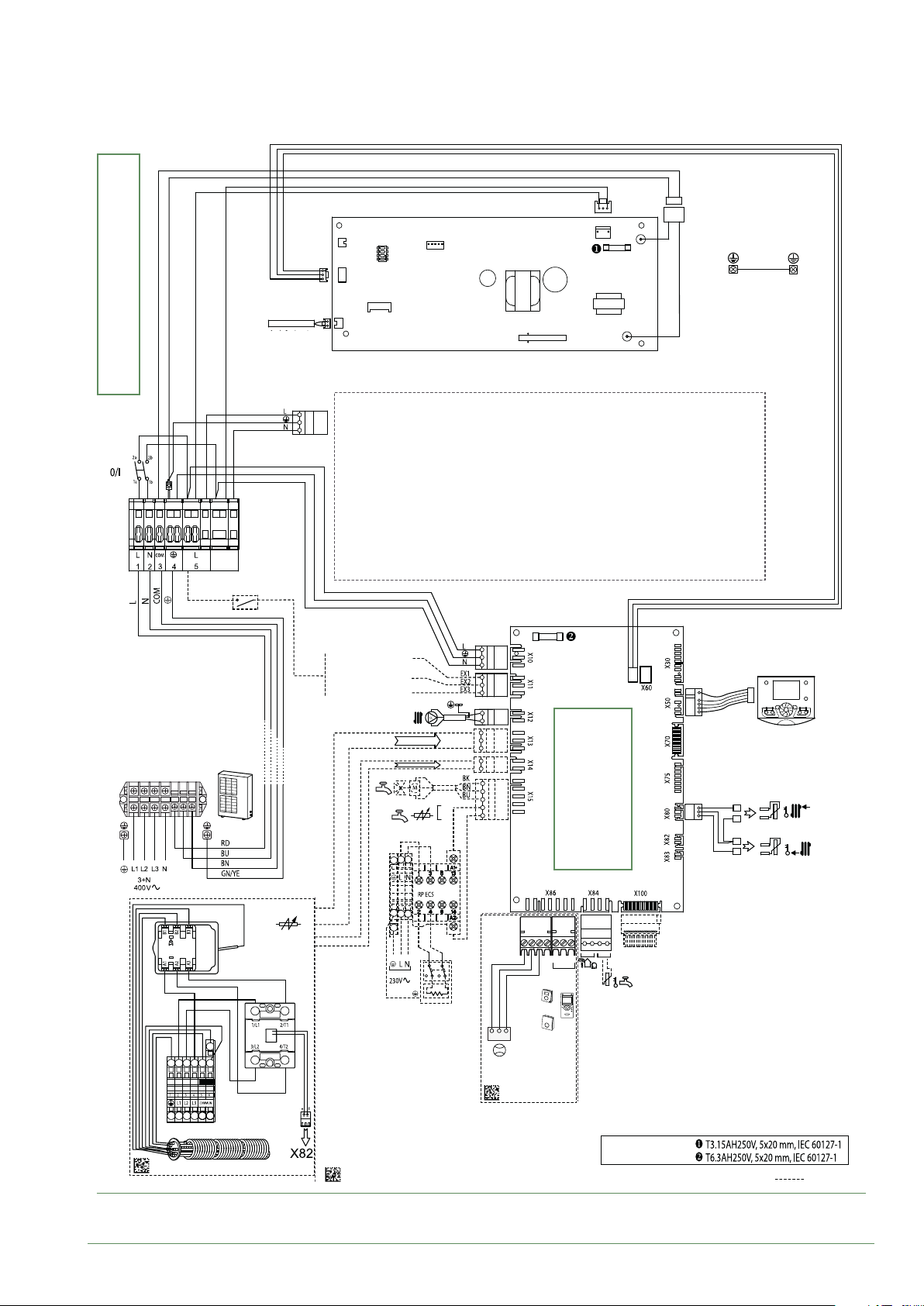
CN21
Débitmètre / Flowmeter (SHP)
CN1
FUSE 250V/3.15A
relay (see g. 34, page 40).
Condensation
sensor
Connection to terminal blocks and power
External
component contact
Power limitation
Taris (day/night)
External faults
CN18
2 circuit option
FUSE 250V/6.3A
1 2 3L1
L2 L3 N
Connections on the
(see g. 36, page 43).
heat pump controller,
accessories and options
3 2 1
Ou/
Ou/
Or
3 2 1
3 2 1
Or
Ou/
Or
Débitmètre /
Flowmeter
Flow-meter
00124534-3-B
Caractéristiques fusibles
Fuse specications
00124534-6-B
3 phase electrical backup
U0531725-B
Fuse specifications
g. 44 - Electrical cabling of 3-phase hydraulic unit (excluding connections made by installer)
Flow
sensor
Return
sensor
/
Options
Waterstage / Installation / 2011 - EN
- 73 -
Page 74
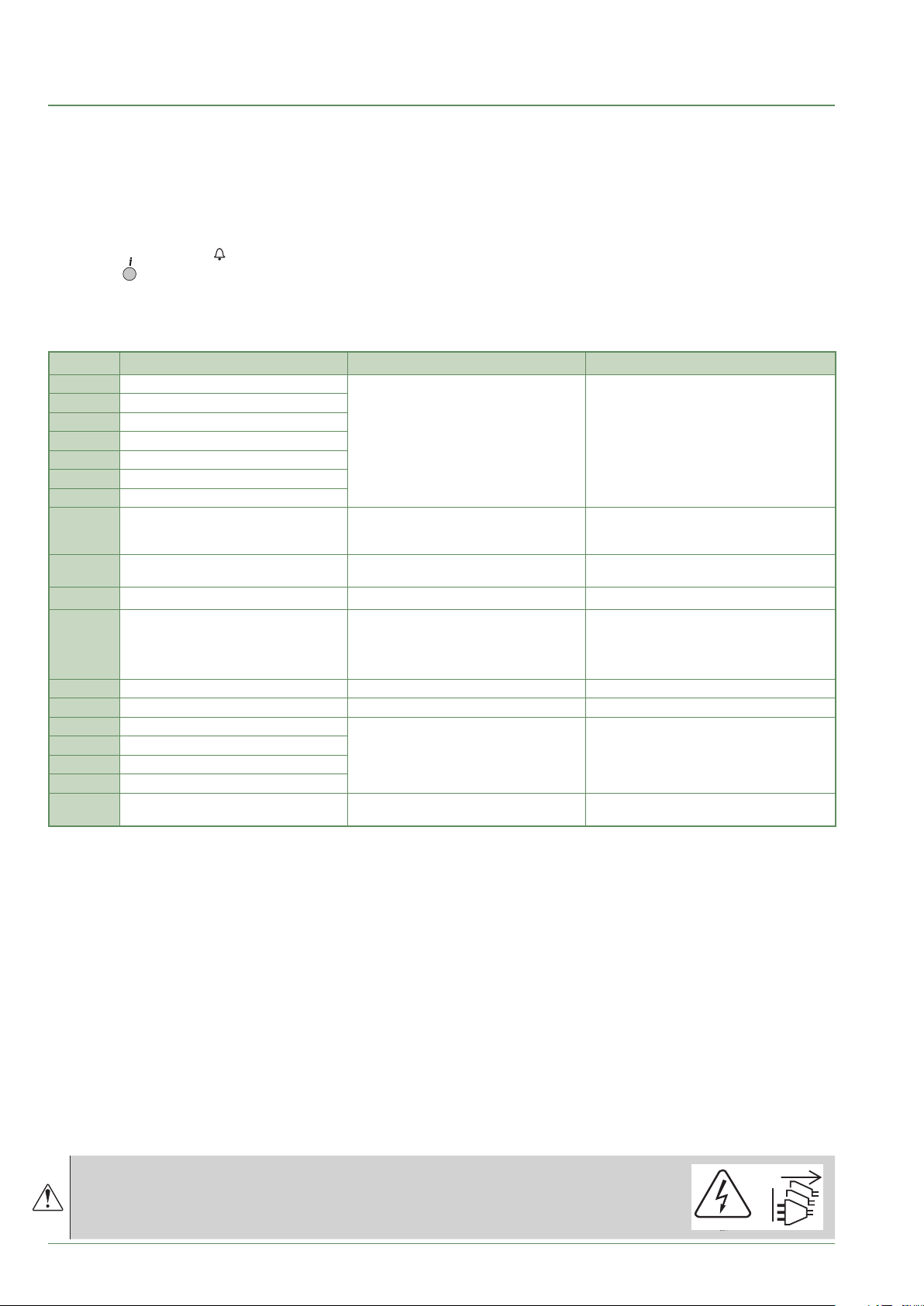
Fault Diagnosis
Depending on whether the fault comes from the outdoor unit or the hydraulic unit, the fault may be indicated by the
digital display or the LED on the interface cards.
Faults in the Hydraulic Unit
►
Faults or breakdowns on the hydraulic unit are indicated by the display on the user interface.
The display shows the symbol.
Press the key for more details on the origin of the fault.
When the error has been resolved, the faults are re-initialised at zero automatically.
Hydraulic unit: Fault visible on the digital display.
Error Designation Probable causes Proposed actions
10 Outside sensor
32 Flow sensor 2
33 Flow sensor HP
44 Return sensor HP
50 DHW sensor 1
60 Room sensor 1
65 Room sensor 2
83 BSB, short circuit
127 Legionella temp
212 Internal comm failure Unplugged or disconnected sensor. Check the sensor's wiring.
356 Flowmeter Insucient ow.
369 External External safety triggered EX3. -
370 Thermodynamic source See details page 74. -
441 BX31 no function
442 BX24 no function
443 BX33 no function
444 BX34 no function
516 Heat pump missing
Short-circuit.
Unplugged or disconnected sensor.
Faulty sensor.
Other fault.
Wiring problem (between the sensor
or remote control, display and
controller).
Anti-legionella temp setpoint not
reached.
Short-circuit.
Unplugged or disconnected sensor.
Faulty sensor.
Other fault.
Loss of connection between
controller and HP.
Check the sensor's wiring.
Replace the sensor.
Check the wiring.
Check the wiring of the DHW backup /
boiler connection.
Check the opening of the valves of the
installation.
Check the owmeter's wiring.
Replace the owmeter.
Check the sensor's wiring.
Replace the sensor.
Check the wiring between X60 and the
interface board.
Before any maintenance operation,
ensure that the general power supply is switched o.
Frost protection is not available when the heat pump is not powered up.
- 74 -
Waterstage / Installation / 2011 - EN
Page 75

Hydraulic unit: Flashing of the LED visible on the interface card.
Outdoor unit
Error number
11 1 Flash 1 Flash Communication error between Hydraulic unit and Outdoor unit.
23 2 Flashs 3 Flashs Connection forbidden (series error).
31 3 Flashs 1 Flash Indoor unit power supply abnormal.
32 3 Flashs 2 Flashs Serial communication error between Controller /Interface PCBs.
41 4 Flashes 1 Flash Heat pump capacity signal error (Open or short).
42 4 Flashes 2 Flashes Hydraulic unit heat-exchange thermistor Error.
61 6 Flashs 1 Flash Outdoor unit power supply abnormal.
62 6 Flashs 2 Flashs Outdoor unit main PCB error.
63 6 Flashes 3 Flashes Inverter error.
64 6 Flashes 4 Flashes Active lter error.
65 6 Flashs 5 Flashs Outdoor unit IPM error.
67 6 Flashs 7 Flashs Outdoor unit power short interruption error (protective operation).
68 6 Flashs 8 Flashs Outdoor unit magnetic relay error.
71 7 Flashes 1 Flash Discharge thermistor error.
72 7 Flashes 2 Flashes Compressor thermistor error.
73 7 Flashes 3 Flashes Heat-exchange thermistor (outlet / intermediate) error.
74 7 Flashes 4 Flashes Outdoor thermistor error.
77 7 Flashs 7 Flashs Outdoor unit heat sink temp. thermistor error.
78 7 Flashes 8 Flashes Expansion valve thermistor error.
84 8 Flashes 4 Flashes Current sensor error.
86 8 Flashes 6 Flashes Pressure sensor error / Pressure switch error.
94 9 Flashes 4 Flashes Current trip.
95 9 Flashes 5 Flashes Detection of compressor position error / Compressor start up error.
97 9 Flashes 7 Flashes Outdoor unit fan1 motor error.
98 9 Flashes 8 Flashes Outdoor unit fan2 motor error.
A1 10 Flashes 1 Flash Discharge temperature protection.
A3 10 Flashes 3 Flashes Compressor temperature protection.
A4 10 Flashs 4 Flashs Outdoor unit pressure error.
A5 10 Flashes 5 Flashes Low pressure abnormal.
A9 10 Flashs 9 Flashs Current overload error.
-
-
LED 2 (green) LED 1 (red)
Continuous
LED display
Continuous ashing
(1 sec On / 1 sec O)
lighting
Error contents
Pump down operation.
O Defrosting.
Waterstage / Installation / 2011 - EN
- 75 -
Page 76
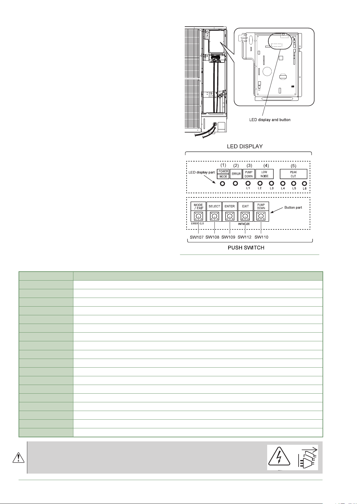
Faults displayed on the single
►
phase outdoor unit
To access the electronic board, you must remove the
front (right-hand) facing from the outdoor unit.
Faults are coded by LED ashes.
When an error occurs:
The LED "ERROR" (2) blinks.
Press once on the switch "ENTER" (SW109).
The "ERROR" (2) LED blinks several times depending
on the error's type (see below).
g. 45 - Location of switches and LED on single phase
LED display Error contents
1 Flash Serial forward transfer error.
2 Flashes Discharge thermistor error.
3 Flashes Pressure switch error.
4 Flashes Heat-exchange thermistor (outlet) error.
6 Flashes Expansion valve thermistor error.
7 Flashes Outdoor temperature thermistor error.
8 Flashes Compressor thermistor error.
9 Flashes Transistor PCB error.
11 Flashes Discharge temperature error (permanent stoppage).
12 Flashes Compressor temperature error (permanent stoppage).
13 Flashes Over current error (permanent stoppage).
15 Flashes Compressor start up error (permanent stoppage).
16 Flashes Fan motor 1 error (permanent stoppage).
17 Flashes Fan motor 2 error (permanent stoppage).
18 Flashes Inverter error.
20 Flashes Low pressure error.
23 Flashes Discharge pressure sensor error.
24 Flashes Suction pressure sensor error.
outdoor unit
Before any maintenance operation,
ensure that the general power supply is switched o.
Frost protection is not available when the heat pump is not powered up.
- 76 -
Waterstage / Installation / 2011 - EN
Page 77
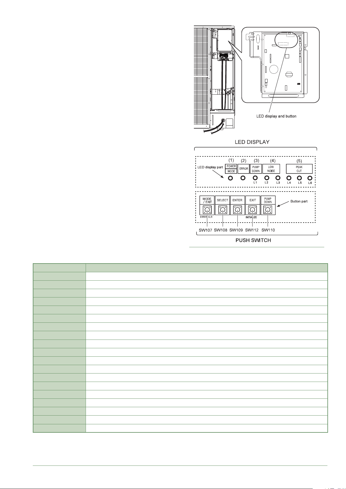
Faults displayed on the 3-phase
►
outdoor unit
To access the electronic board, you must remove the
front (right-hand) facing from the outdoor unit.
Faults are coded by LED ashes.
When an error occurs:
The LED "ERROR" (2) blinks.
Press once on the switch "ENTER" (SW109).
The "ERROR" (2) LED blinks several times depending
on the error's type (see below).
g. 46 - Location of switches and LED on 3-phase
outdoor unit
LED display Error contents
1 Flash Serial forward transfer error.
2 Flashes Discharge thermistor error.
3 Flashes Pressure switch error.
4 Flashes Heat-exchange thermistor (outlet) error.
6 Flashes Expansion valve thermistor error.
7 Flashes Outdoor temperature thermistor error.
8 Flashes Compressor thermistor error.
9 Flashes Transistor PCB error.
11 Flashes Discharge temperature error (permanent stoppage).
12 Flashes Compressor temperature error (permanent stoppage).
13 Flashes Over current error (permanent stoppage).
14 Flashes Detection of compressor position error (permanent stoppage).
15 Flashes Compressor start up error (permanent stoppage).
16 Flashes Fan motor 1 error (permanent stoppage).
17 Flashes Fan motor 2 error (permanent stoppage).
18 Flashes Inverter error.
20 Flashes Low pressure abnormal.
23 Flashes Discharge pressure sensor error.
24 Flashes Suction pressure sensor error.
Waterstage / Installation / 2011 - EN
- 77 -
Page 78
Maintenance of the installation
Before any maintenance operation,
ensure that the general power supply is switched o.
Hydraulic checks
►
If frequent rells are required it is absolutely
essential that you check for any leaks. If
relling and a pressure reset are necessary,
check what type of uid was used initially.
Recommended lling pressure: between 1 and 2 bar
(the exact lling pressure is determined by the water
pressure in the installation).
Every year,
- Check the expansion circuit pressure (pre-ination of
1 bar) and the correct operation of the safety valve.
If the installation is tted with a hot water tank:
- Check the safety valve on the cold water supply inlet.
Make it operate as advised by the manufacturer.
- Check the back ow preventer.
Checking the outdoor unit
►
- Remove any dust from the exchanger, if necessary,
while making sure not to damage the blades.
- Straighten the blades using a comb.
- Check that there is nothing blocking the air ow.
- Check the fan.
- Verify that condensate drain is not obstructed.
• Checking the refrigeration circuit
If the amount of refrigerant in the system exceeds
2kg (models > 10kW), the refrigeration circuit must be
checked annually by an approved engineer (they must
have a certicate of competence for the handling of
refrigerants).
- Check there are no leaks (connections, valves…).
Electrical checks
►
- Check the connections and re-tighten if necessary.
- Check the state of the cables and plates.
Other maintenance
Emptying the hydraulic unit
►
- Remove the front panel of the hydraulic unit.
- Open the drain plug,
- Check that the hydraulic unit's bleeder valve opens
automatically,
- Open the installation’s bleeder valve(s).
- 78 -
Distribution valve
►
If the installation is tted with a hot water tank.
Ensure the distribution valve is tted in the correct
direction.
Channel AB: Outlet to the hydraulic unit.
Channel A open: Return from DHW tank.
Channel B open: Return from the heating circuit.
Waterstage / Installation / 2011 - EN
Page 79
Instructions for the end user
Explain to the user how his installation operates, in particular the functions of the room sensor and
the programmes accessible to them via the user interface.
Emphasise that a heated oor has signicant inertia and that therefore any adjustments must be made
gradually.
Also explain to the end user how to check the lling of the heating circuit.
End-of-life of the appliance
The appliances must be dismantled and recycled by a specialised service. The appliances must not, under
any circumstances, be thrown out with household waste, bulky waste or at a tip.
At the end of its service life, please contact your installer or local representative to proceed with its dismantling
and recycling.
This unit is identied by this symbol. It means that all electrical and electronic products must not be included in household waste.
A specic recycling system for this type of product has been set up in European Union countries (*), Norway, Iceland and Liechtenstein.
Do not try to dismantle this product yourself. It may have damaging eects on your health or on the environment.
Reprocessing of the refrigerant, lubricant and other parts may be performed by a qualied installer in compliance with the local and national legislation in force.
This unit must be recycled by a specialised service and in no case may it be thrown away with household waste, rubble or in a landll.
Please contact your installer or local representative for more .
* Depending on the national regulations of each member state.
Waterstage / Installation / 2011 - EN
- 79 -
Page 80
Quick-start procedure
Before switching on the hydraulic unit:
• Check the electric wiring.
• Check the refrigeration circuit and make sure the it has been gassed.
• Check the hydraulic circuit's pressure (1 to 2 bar), check that the heat pump has been bled, along with the rest of
the installation.
• Make sure that ALL DIP SW on the interface board are OFF before starting up.
Start-up check-list
►
Before starting-up
▼
OK Not compliant
Sight checks Outdoor unit (see chapter "Installation of the outdoor unit", page 18).
Location and ttings, condensate evacuation.
Comply with distances from obstacles.
Hydraulic checks Hydraulic unit (see chapter "Installation of the hydraulic unit", page 20).
Connection of pipes, valves and pumps (heating circuit, DHW).
Installation water volume (expansion vessel of adequate capacity?).
No leaks.
Main system pressure and degassing.
Refrigeration connections and checks (see chapters " Refrigeration connections", page 22).
Check the refrigeration circuits (sealing, no dust or humidity).
Connections between units (pipe length, are tightening torque...).
Installation of HP pressure gauges on the gas line (large tube).
Pump down mandatory.
Nitrogen leak test (~ 10 bar).
Opening of refrigeration valves to outdoor unit.
Filling hydraulic unit and pipes with refrigerant.
Electrical checks Outdoor unit (see chapter " Electrical connections", page 34).
Main power supply (230 V or 400 V).
Protection by rated circuit breaker.
Cable dimensions.
Earth connection.
Hydraulic unit (see chapter "Electrical connections on the hydraulic unit side", page 38).
Connection to outdoor unit (L, N, Earth or 3 L, N, Earth).
Sensors connection (positioning and connections).
Distribution valve connections (boiler and DHW) and circulation pump.
Power supply and protection of electric backup (option).
- 80 -
Waterstage / Installation / 2011 - EN
Page 81
Starting-up
▼
Quick Start Procedure (see chapter " Commissioning", page 44 and § " Controller Menu", page 50).
Close the installation's main circuit breaker (outdoor unit power supply)
2 hours before testing => Preheating of the compressor.
Press the On/O Switch => Initialisation takes several seconds.
Operation of the heating circulation pump.
Outdoor unit starts after 4 mins.
Congure Time, Date and Heating circuit, DHW period programs if dierent from the default values.
Congure the hydraulic circuit.
Adjust the heating gradient.
Adjust the max ow setpoint.
Outdoor unit checks
Operation of fan(s), compressor.
Current measurement.
After several minutes measure the dierence in air temperature.
Check condensation and evaporation pressure/temperature.
Hydraulic unit checks
After 15 mins of operation.
Primary water temp. dierence.
Operation of heating, boiler backup, etc.
Control (see chapter " Controller Menu", page 50)
Settings, maintenance, checks.
Program the heating periods.
Adjust the setpoints for the heating circuits if dierent from the default values.
Setpoint display.
OK Not compliant
Explanations of use
The heat pump is ready for operation !
Waterstage / Installation / 2011 - EN
- 81 -
Page 82
Settings sheet
►
Setting Description Set to. Menus
Preliminary settings
20 language operator
section
1 hour / minutes time & date
2 day / month time & date
3 year time & date
5700 installation cong. conguration
Heating circuit No. 1
if 2 circuits = the least warm one (e.g.: oor)
710 comfort setpoint HC1 adjust.
712 reduced setpoint HC1 adjust.
720 heating curve slope HC1 adjust.
741 ow temp setpoint max HC1 adjust.
750 room inuence HC1 adjust.
790 / 791 optimis. at switch-on / off HC1 adjust.
834 servomotor travel time HC1 adjust.
850 / 851 oor drying HC1 adjust.
Heating circuit No. 2 (with 2nd circuit option)
= the warmest one (e.g.: radiators)
1010 comfort setpoint HC2 adjust.
1012 reduced setpoint HC2 adjust.
1020 heating curve slope HC2 adjust.
1041 ow temp setpoint max HC2 adjust.
1050 room inuence HC2 adjust.
1090 / 1091 optimis. at switch-on / off HC2 adjust.
1134 servomotor travel time HC2 adjust.
1150 / 1151 oor drying HC2 adjust.
Domestic Hot Water (with DHW kit)
1610 nominal DHW temp. setpoint DHW
1612 reduced DWH temp. setpoint DHW
1620 DHW release DHW
1640 to 1642 legionella cycle DHW
5024 DHW switch-on differ. DHW tank
5030 charging time limitation DHW tank
5061 heater release DHW tank
Setting Description Set to. Menus
Boiler backup
3700 OT.switch-on authoris. addit. gen.
3705 swith-off delay addit. gen.
Miscellaneous
6420 input H33 function 1 conguration
6100 OT sensor correction conguration
6120 frost protection on/off conguration
6205 reset settings conguration
6220 software version conguration
6711 reset heat pump error
Cooling
5711 cooling unit 2 pipes conguration
Faults (if a fault occurs, press"Info" key)
No. 10 outdoor sensor
No. 33 ow temp. sensor
No. 44 return temp. sensor
No. 50 DHW temp. sensor
No. 60 room sensor 1
No. 65 room sensor 2
No. 105 maintenance message
No. 121 HC1 ow T not reached
No. 122 HC2 ow T not reached
No. 127 leg. prot. T not reached
No. 369 external fault (EX3)
No. 370 outdoor unit connect error
6711 reset heat pump error
Heat pump
2844 switch-off temp max heat pump
2884 OT auth. to start elec. aux. heat pump
2920 Pk day clear (EX1) rel / lock heat pump
Swimming pool (with "swimming pool" kit)
2056 generator setpoint Sw pool
Outdoor unit faults (see page 75)
- 82 -
Waterstage / Installation / 2011 - EN
Page 83
Commissioning technical datasheet
►
Site Installer
Outdoor unit
Refrigerant type Refrigerant load kg
Checks Operating voltage & current on outdoor unit
Compliance with positioning distances L/N or L1/N V
Condensate evacuation correct L2/N V
Electric connections / connections tightness L3/N V
No GAS leaks (unit ID No.: ) L/T or L1/T V
Installation refrigeration connection correct (length
m)
Taken in operation when HOT L3/T V
Compressor discharge temperature °C N/E V
Liquid line temp. °C
Condensation
temperature
Tank water output temperature °C ΔCondensation Temp. °C
Tank water input temperature °C ΔSecondary Temp. °C
Evaporation temperature LP = bar °C
Suction Temp. °C Overheating °C
Battery air input temperature °C ΔEvaporation Temp. °C
Battery air output temperature °C ΔBattery Temp. °C
Hydraulic network on hydraulic unit
Secondary system
Domestic hot water; tank type
Estimated water volume of secondary system L
Options & accessories
Power supply for electric backup Room sensor T75
Correct location of room sensor Wireless room sensor T78
2 circuit kit
Boiler connection kit
Cooling kit
Control settings
Conguration type
Essential settings
Serial No.
Model Model
HP = bar °C Under-cooling °C
Underoor heating system
Fan coils
}
Hydraulic unit
L2/T V
Icomp A
}
}
}
}
}
}
Circulation pump brand TypeLT Radiators
DetailsDHW kit
Serial No.
Waterstage / Installation / 2011 - EN
- 83 -
 Loading...