

Fujitsu Waterstage WOYG160LJL, Waterstage WOYK150LJL, Waterstage WSYK170DJ9, Waterstage WOYK170LJL, Waterstage WSYG160DJ6 Installation Manual

U0651595_2011_EN_2
10/09/2019
Outdoor unit
WOYG160LJL
WOYK150LJL
WOYK170LJL
Hydraulic unit
WSYG160DJ6
WSYK170DJ9
INSTALLATION
Air to Water Heat Pump Split single service
For professionals. To be kept by the user for future reference
EN

■ Installation and maintenance rules
The appliance must be installed and maintained
by an approved professional in accordance with
current regulations and codes of practice.
• Warning, hydraulic unit should not be installed
in an air current.
■ Handling
The outdoor unit must not be placed in a horizontal
position during transport.
If not kept upright during transport, the appliance
could be damaged through displacement of
the refrigerant and damage to the compressor
suspension.
Any damage caused by transportation in a horizontal
position is not covered by the warranty.
If necessary, the outdoor unit may be tilted only
during manual handling (to go through a door or up
a staircase). This operation must be conducted very
carefully and the appliance must be immediately
restored to the upright position.
■ Containment of refrigeration circuits
All refrigeration circuits are sensitive to contamination
from dust and moisture. If such pollutants penetrate
the refrigeration circuit, they can aect the reliability
of the heat pump.
Make sure that the connections and refrigeration
circuits (hydraulic unit, outdoor unit) are
protected correctly.
In the event of a subsequent failure and following
an inspection, the presence of moisture or
foreign bodies in the compressor oil would
automatically void the warranty.
- Check upon receipt that the ttings and refrigeration
circuit caps mounted on hydraulic unit and outdoor
unit are properly seated and secured (cannot be
loosened with bare hands). If this is not the case,
tighten them using a C spanner.
- Check also that the refrigeration connections are
sealed (plastic caps or tubes crimped at the ends
and brazed). If the caps must be removed during
the installation (tubes to be re-cut for example),
put them back as soon as possible.
■ Hydraulic connections
The connection must comply with industry standard
practice according to current regulations.
Remember: Seal everything when tting in
accordance with industry standard practice for
plumbing work:
- Use suitable seals (bre gasket, O-ring).
- Use Teon or hemp tape.
- Use sealing paste (synthetic depending on the
case).
Use glycol/water mix if the minimum ow
temperature is set below 10°C. If you are using a
glycol/water mix, arrange for an annual check on the
quality of the glycol. Use monopropylene glycol only.
The recommended concentration is 30% minimum.
Never use monoethylene glycol.
• In some installations, the presence of dierent
metals can cause corrosion problems; the
formation of metal particles and sludge can
appear in the hydraulic circuit.
• In this case, it is advisable to use a corrosion
inhibitor in the proportions indicated by the
manufacturer.
• You must also ensure that treated water does
not become corrosive.
■ Electrical connections
2
1
3
• Before any maintenance operation, ensure
that the general power supply is switched o.
• Specications of electricity supply
The electrical installation must be carried out in
accordance with prevailing rules.
Electrical connections will only be made once all
other installation operations (fastening, assembly,
etc.) have been completed.
Warning!
The contract signed with the energy provider must
be sucient not only to cover the heat pump's power
requirements but also the combined sum of all the
appliances likely to be operating at the same time. If
the power is too low, check the power rating stated
in your contract with your energy provider.
Never use a power socket for the power supply.
The heat pump must be supplied directly with power
(without external switch) by special protected leads
from the electric panel via dedicated bipolar circuit
breakers, C curve for the outdoor unit, C curve for
the electrical heating and domestic water backups
(see tables page 35).
The electrical installation must be tted with a 30mA
RCD.
This appliance is designed to operate using a
nominal voltage of 230 V or 400 V, +/- 10%, 50 Hz
(depending on model).
• General remarks on electrical connections
It is essential to maintain neutral-phase polarity
when making electrical connections.
Rigid wires are preferable for xed installations,
particularly in a building.
Tighten the cables using the cable glands to prevent
the feed wires from being accidentally disconnected.
The earth connection and its continuity must be
ensured.
• Cable glands
To ensure the stability of power (Low Voltage) and
sensor (Extra-Low Voltage) cables, it is essential
that the cable glands are tightened according to the
following recommendations:
Size of cable
gland (PE)
(mm)
PG7 1 to 5 1.3 1
PG9 1.5 to 6 3.3 2.6
PG16 5 to 12 4.3 2.6
Diameter of
cable
(mm)
Cable gland
tightening
torque
(check-nut)
(N.m)
Coupling net
tightening
torque
(N.m)
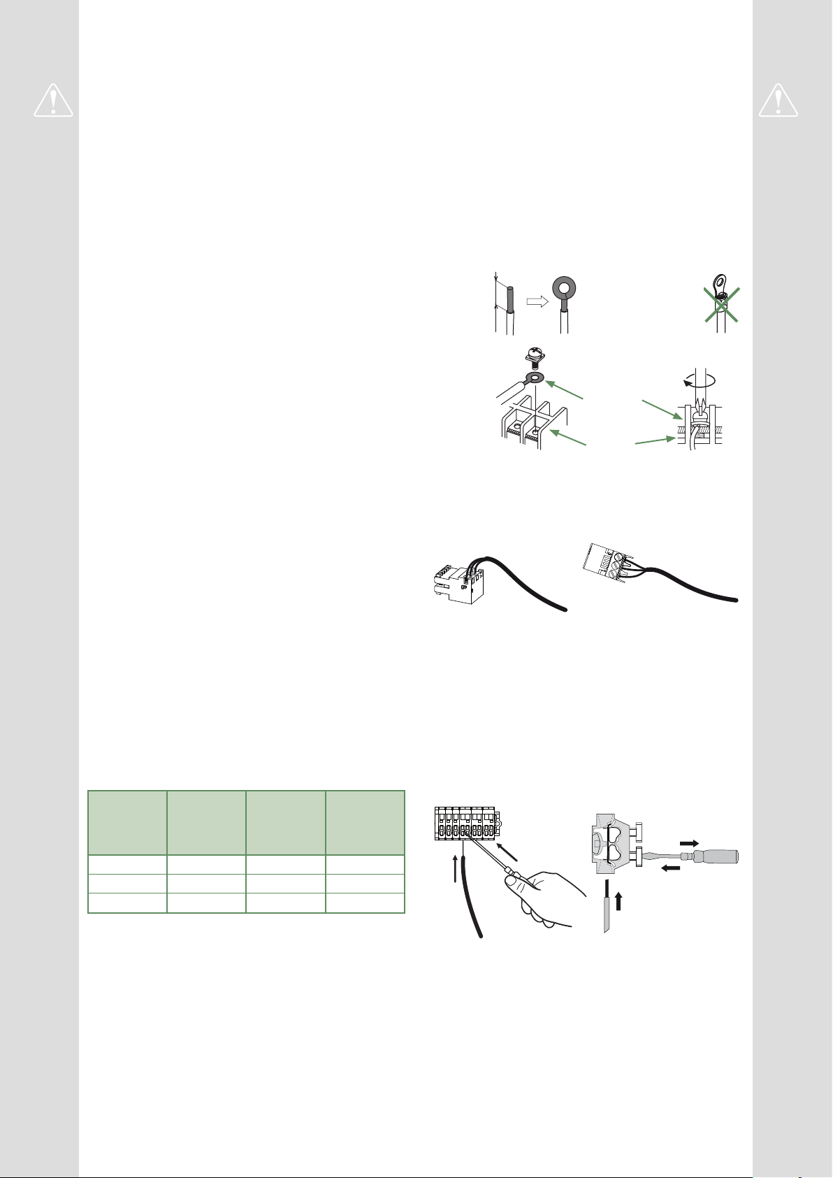
• Connecting to screw terminals
The use of ring, spade or blade terminals or
caps is prohibited.
- Always select wire that complies with current
standards.
- Bare the end of the wire to around 25 mm.
- With round end pliers, form a loop with a diameter
which matches the tightening screws on the
terminal.
- Tighten the terminal screw rmly onto the
loop created. Insucient tightening can cause
overheating, leading to breakdown or even re.
Rigid wires
25 mm
Loop
Lug on
exible wires
prohibited
Screw and special
washer
Terminal
• Connecting to controller boards
- Remove the corresponding connector and make
the connection.
Pre-cabled bundle connector and/or screw connector
• Connecting to spring terminals
- Bare the end of the wire to around 12 mm.
- Push the spring with a screwdriver so that the wire
enters the cage.
- Slide the wire into the opening provided for this
purpose.
- Remove the screwdriver and then check that the
wire stays gripped by the cage by pulling on it.

This appliance must be installed by qualied personnel holding a certicate of competence in the
handling of refrigerants.
Contents
Description of the equipment 6
Packing .................................6
Unpacking and supplies ....................6
Denitions ...............................6
Optional equipment ........................6
Operating Range ..........................6
General characteristics .....................7
Description .............................12
Operating principle .......................14
Installation 16
Installation of refrigeration connections ........16 Installation of the outdoor unit ...............18
Installation of the hydraulic unit ..............20
Refrigeration connections 22
Rules and precautions .....................22
Shaping the refrigeration pipes ..............22
Checks and connection ....................25
Filling the installation with gas ...............26
Hydraulic connections 30
Connecting the hydraulic unit to the heating circuit ..30
Filling and bleeding the installation ...........31
Heating circulation pump speed settings .......32
Electrical connections 34
Cable dimensions and protection rating .......35
Outside sensor ..........................42
Electrical connections on the outdoor unit side ..36
Electrical connections on the hydraulic unit side ..38
Room sensor (optional) ....................42
Commissioning 44
Controller Interface 46
User Interface ...........................46
Display Description .......................47
Installer Menu ...........................48
- 4 -
Navigating the Menus .....................48
Modifying Settings ........................49
Temperature control ......................50
Waterstage / Installation / 2011 - EN

Controller Menu 52
Menu Structure ..........................52
Installed options .........................53
Hydraulic conguration ....................53
Heat Pump Conguration ..................58
System status ...........................60
Auxiliary functions ........................62
Settings ................................64
Easy Start ..............................68
Basic Hydraulic Layout 70
Electrical Cabling Plans 72
Fault Diagnosis 76
Faults in the Hydraulic Unit .................76 Faults in the Outdoor Unit ..................77
Maintenance of the installation 78
Hydraulic checks .........................78
Checking the outdoor unit ..................78
Electrical checks .........................78
Other maintenance 79
Emptying the hydraulic unit .................79 Distribution valve .........................79
Quick-start procedure 80
Start-up check-list ........................80 Commissioning technical datasheet ..........82
Instructions for the end user 83
Waterstage / Installation / 2011 - EN
- 5 -

Description of the equipment
Packing
►
• 1 package : Outdoor unit.
• 1 package : Hydraulic unit and outside temperature
sensor.
Unpacking and supplies
►
While the courier is still present, carefully check the
general appearance of the appliances and check
that the outdoor unit has not been laid in a horizontal
position.
In the event of a dispute, send any relevant reservations
to the carrier in writing within 48 hours and send a copy
of the letter to Customer Services.
Packing contents list
Heat Pump Outdoor unit Hydraulic unit
Model Reference Code
Waterstage SHP 16 WOYG160LJL WSYG160DJ6
Waterstage SHP TRI 15 WOYK150LJL
Waterstage SHP TRI 17 WOYK170LJL
Denitions
►
- Split: The heat pump consists of two elements
(an outdoor unit to be installed outdoors and a hydraulic
unit to be installed inside the dwelling).
- Air/water: The surrounding air is the energy source.
This energy is transmitted to the heating circuit water
by the heat pump.
- Inverter: The fan and compressor speeds are
modulated according to the heating requirements.
This technology enables you to save on energy and
operate on a single-phase power supply, whatever
the heat pump's output, by avoiding pulling signicant
amounts of current at start-up.
- COP (Coecient of Performance): This is the
relationship between the energy transmitted to the
heating circuit and consumed electrical energy.
WSYK170DJ9
Optional equipment
►
• Dual circuit kit (code UTW-KZSXJ)
for connecting 2 heating circuits.
• Regulation extension kit (code UTW-KREXD)
to manage a 2nd heating circuit, swimming pool,
telephone modem etc...
• DHW kit (code UTW-KDWXD)
for connecting a mixed DHW tank
(with built-in electrical backups).
• Boiler connection kit (code UTW-KBSXJ)
for connecting a boiler to the heat pump.
• Room thermostat (code UTW-C55XA),
Wireless room thermostat (code UTW-C58XD)
for correcting the ambient temperature.
• Remote control (code UTW-C74TXF or UTW-C74HXF),
Wireless remote control (code UTW-C78XD)
for correcting the ambient temperature and
programming the heat pump.
• Cooling kit (code UTW-KCLXD).
• High ow rate circulation pump kit (code UTW-PHFXG)
for the installation of 1 underoor heating circuit.
Operating Range
►
This heat pump provides:
- Heating in winter,
- The management of electrical backups, for extra
heating on the coldest days,
or
- Installation with boiler connection* for extra heating on
the coldest days,
- Management of two heating circuits*,
- Production of domestic hot water* (provided that it is
combined with a mixed DHW tank),
- Cooling in summer* (for underoor heating-cooling
system or fan-convectors).
*: These options require the use of additional kits
(see chapter "Required accessory" or "Optional equipment").
- 6 -
Waterstage / Installation / 2011 - EN

General characteristics
►
Model name Waterstage SHP 16 TRI 15 TRI 17
Rated heating performances (outdoor temp. / ow temp.)
Heat output
+7°C/+35°C - Underoor heating system kW 16.00 15.00 17.00
-7°C/+35°C - Underoor heating system kW 14.50 13.20 15.00
+7°C/+55°C - Radiator kW 14.50 13.20 15.00
-7°C/+55°C - Radiator kW 10.90 13.20 14.20
Power consumption
+7°C/+35°C - Underoor heating system kW 3.86 3.46 4.10
-7°C/+35°C - Underoor heating system kW 5.27 4.55 5.32
+7°C/+55°C - Radiator kW 5.58 4.77 5.49
-7°C/+55°C - Radiator kW 5.89 6.77 7.40
Coecient of performance (COP) (+7°C/+35°C) 4.15 4.33 4.15
Electrical specications
Electrical voltage (50 HZ) V 230 400 400
Maximum current for appliance A 28 14 14
Nominal current A 17.2 6.43 7.4
Maximum current of the Heating system electrical backup A 26.1 39 39
Power of the Heating system electrical backup kW
6 kW
(single phase)
9 kW
(3-phase)
9 kW
(3-phase)
Circulation pump actual power consumption W 39.5 39.5 39.5
Maximum power consumed by the outdoor unit W 6300 6770 7400
Hydraulic Circuit
Maximum operating pressure MPa (bar) 0.3 (3) 0.3 (3) 0.3 (3)
Available heating pressure at nominal point +7°C / +55°C (Δt8) MPa (bar) 0.05 (0.5) 0.055 (0.55) 0.045 (0.45)
Minimum allowed hydraulic ow rate l/h 600 600 600
Miscellaneous
Weight of outdoor unit Kg 137 138 138
Noise level at 5 m 1 (Outdoor unit) dB (A) 45 45 45
Sound power level in accordance with EN 12102 2 (Outdoor unit) dB (A) 67 67 67
Weight of hydraulic unit (empty / full of water) Kg 53 / 75 53 / 75 53 / 75
Hydraulic unit water capacity l 30 30 30
Noise level at 1 m 1 (Hydraulic unit) dB (A) 37 37 37
Sound power level in accordance with EN 12102 2 (Hydraulic unit) dB (A) 45 45 45
Heating system operating limits
Outdoor temperature min/max °C -25 / +35 -25 / +35 -25 / +35
Max. heating water ow temperature underoor heating °C 45 45 45
Max. heating water ow temperature low temperature radiator °C 60 60 60
Min. ow water temperature °C 8 8 8
Refrigeration circuit
Gas pipe diameters Inches 5/8 5/8 5/8
Liquid Piping Diameters Inches 3/8 3/8 3/8
Factory ll of refrigerant R410A 3 g 3800 3800 3800
Maximum operating pressure MPa (bar) 4.15 (41.5) 4.15 (41.5) 4.15 (41.5)
Minimum / Maximum length of pipes
Maximum length of pipes
5
Maximum level dierence
(Outdoor unit over hydraulic unit and heating only / Other cases)
4 / 6
m 5 / 15 5 / 15 5 / 15
m 30 30 30
m 25 / 15 25 / 15 25 / 15
1
Sound pressure level at (x) m from the appliance, 1.5m off the ground, open eld
directionality 2.
2
The sound power level is a laboratory measurement of the emitted sound power. It
does not correspond to a measurement of the perceived sound power.
Waterstage / Installation / 2011 - EN
3
Refrigerant R410A as per NF EN 378.1 standard.
4
Filling with refrigerant R410A is done at the factory.
5
Taking into account a possible additional ll of refrigerant R410A (see "Additional
lling", page 28).
6
The announced thermal and acoustic performances are measured with 7.5m length
refrigerant lines.
- 7 -
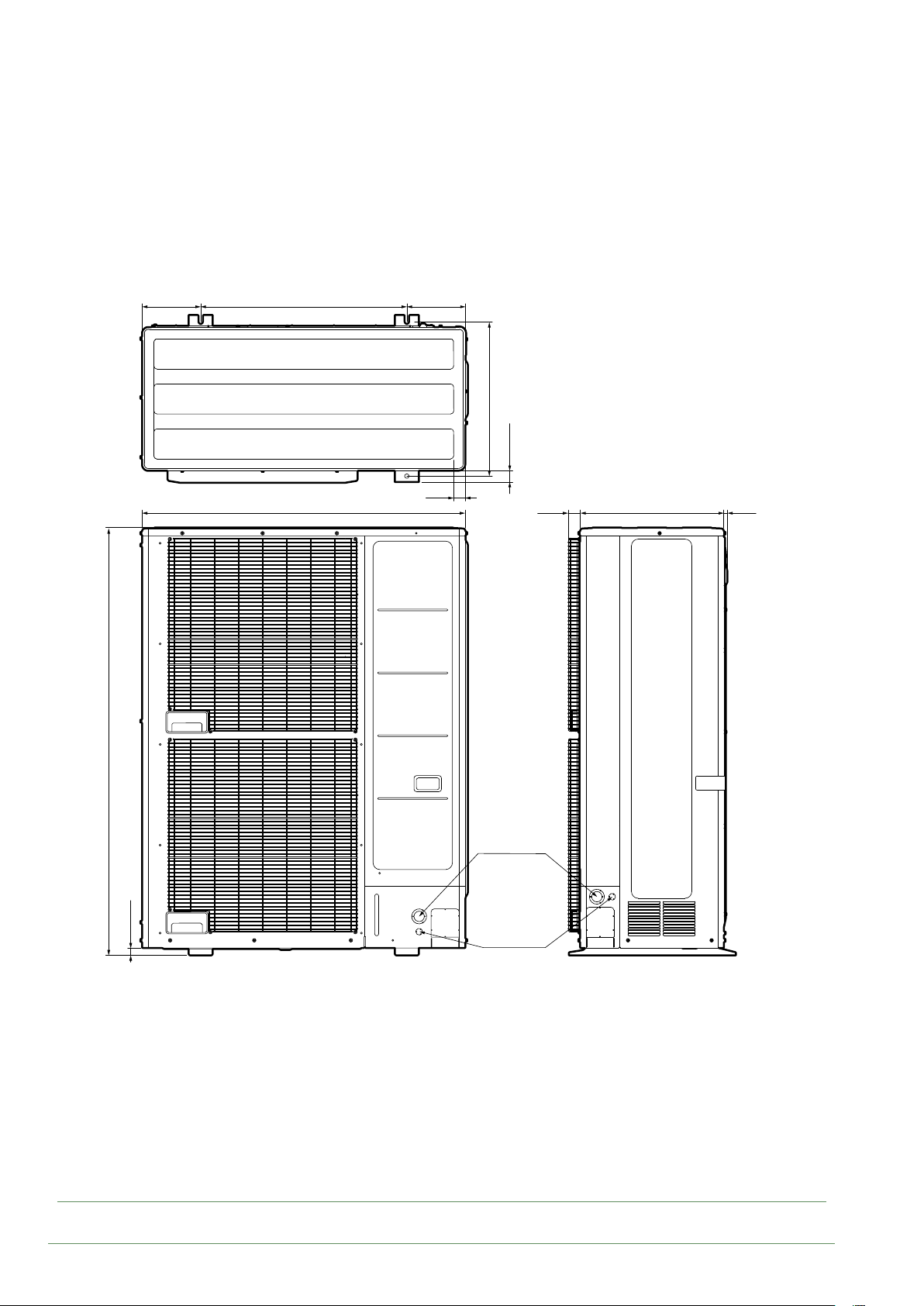
■ Waterstage SHP 16
■ Waterstage SHP TRI 15
Waterstage SHP TRI 17
196 196
688
40
1080
515.5
37.7
39.3
480
12.1
1428
23.6
Ø50
Ø34.5
Ø22.2
g. 1 - Dimensions of outdoor units (in mm)
- 8 -
Waterstage / Installation / 2011 - EN
3**
4
8
7
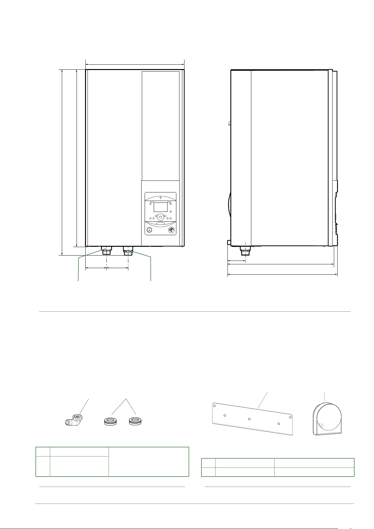
■ Hydraulic unit
805
847
450
9897
Heating return
ø M 26x34
Space requirements of the hydraulic unit, see page 20.
g. 2 - Dimensions of hydraulic unit (in mm)
1*
Heating ow
ø M 26x34
2*
81
471
493
5 6
1 Elbow
Plugs (x9)
2
(depending on
model)
g. 3 - Accessories provided with the outdoor unit
Waterstage / Installation / 2011 - EN
for condensate evacuation.
5 Bracket for attaching hydraulic unit.
6 Outside sensor to monitor the outdoor temp.
g. 4 - Accessories provided with the hydraulic unit
- 9 -

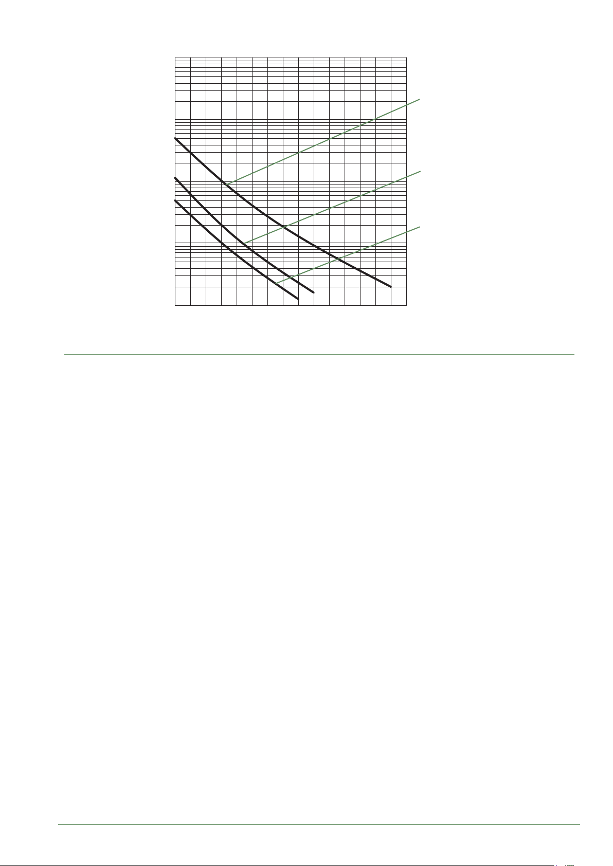
0102030405060708090 100
Variable pressure Constant pressure
mCE
8
7
6
5
4
3
2
1
0
0 0,5 1 1,5 2
1
55
3
1 mbar=10 mmCE=100 Pa
88
77
1
mCE
8
7
6
5
4
3
2
1
3
3
/h
1,5 20,50
m
m/h
0
0 0,5 1 1,5 2
g. 5 - Available hydraulic pressures and ow rates
Outside sensor QAC34
32500
30000
27500
43907
10000
2490
1000
338
-50
-25025 50 75
°C
25000
22500
20000
17500
15000
12500
10000
7500
5000
2500
0
88
77
3
1
HP return sensor
HP ow sensor
1 mbar=10 mmCE=100 Pa
55
1
3
3
/h
1,5 20,50
m
m/h
°C
g. 6 - Ohmic sensor values (Hydraulic unit)
- 10 -
Waterstage / Installation / 2011 - EN
10000
1000
Ohmic value (kΩ)
- Compressor
- Discharge
- Condensation
- Expansion valve
100
10
1
-20 -10 0 10 20 30 40 50 60 70 80 90 100 110 120 130
g. 7 - Ohmic sensor values (Outdoor unit)
- Outdoor unit
- Evaporator inlet
Temperature °C
Waterstage / Installation / 2011 - EN
- 11 -

Description
►
■ Waterstage SHP 16
■ Waterstage SHP TRI 15
Waterstage SHP TRI 17
12
8
13
4
1
3
2
5
9
14
1
2
6
7
11
10
Key:
1. High performance and low noise impeller.
2. Electrical motor with variable "Inverter" operation.
3. "Inverter" control unit.
4. Check lights and buttons.
5. Connection terminal blocks
(power supply and interconnection).
6. Refrigerant storage bottle.
7. 4-way valve.
8. Anti-corrosion treated bodywork.
9. Main circuit electronic expansion valve.
10. Noise and thermally insulated "Inverter" compressor with liquid injection port.
11. Refrigeration connection valves (ared connectors) with protective caps.
12. Holding tank with condensate drain hole.
13. High-performance exchange surface evaporator; anti-corrosion treated hydrophilic aluminium ns and
grooved copper tubes.
14. Solenoid valve for liquid injection.
g. 8 - Outdoor unit components
- 12 -
Waterstage / Installation / 2011 - EN

■ Hydraulic unit
1
13
15
16
8
14
5
2
67
3 4
8
9
10
11
12
5
Key:
1 - Electric box.
2 - User interface.
3 - Start/stop switch.
4 - Pressure gauge.
5 - Heating circulation pump.
6 - Heating ow.
7 - Heating return.
8 - "Gas" refrigeration connection.
9 - "Liquid" refrigeration connection.
10 - Drain valve.
11 - Safety valve.
12 - Flowmeter
13 - Automatic bleeder valve.
14 - Expansion vessel.
15 - HP electrical backup.
16 - Condenser.
g. 9 - Hydraulic unit components
Waterstage / Installation / 2011 - EN
- 13 -
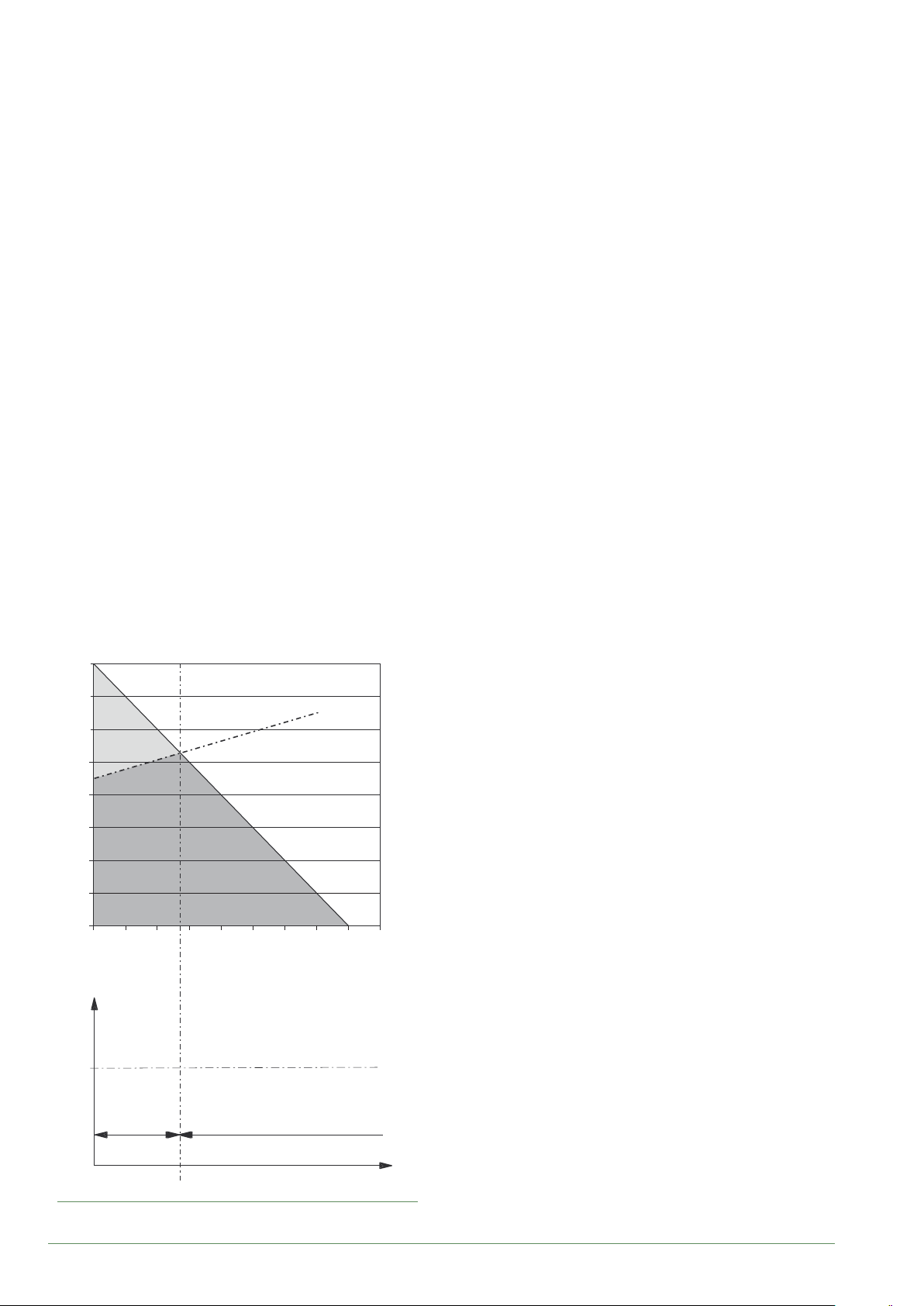
Operating principle
►
The heat pump transmits the energy contained in the
surrounding air into the dwelling to be heated.
The heat pump consists of four main elements, in which
a refrigerant (R410A) circulates.
- In the evaporator (ref. 13, g. 8, page 12):
The calories are taken from the outside air and
transmitted to the refrigerant. Because it has a low
boiling point, it changes from a liquid to a vapour, even
in cold weather (down to -25°C outside temperature).
- In the compressor (ref. 10, g. 8, page 12):
The vaporised refrigerant is pressurised and takes on
even more calories.
- In the condenser (ref. 14, g. 9, page 13):
The energy of the refrigerant is transmitted to the
heating circuit. The refrigerant returns to its liquid state.
- In the expansion valve (ref. 9, g. 8, page 12):
The liqueed refrigerant is returned to a low pressure
and regains its initial temperature and pressure.
The heat pump is equipped with a controller which
controls the room temperature based on the outdoor
temperature measurement. The room thermostat
(option) provides a corrective action for the temperature
control.
The hydraulic unit is tted with an electrical backup or
boiler connection which intervenes to provide additional
heat during the coldest periods.
• Control functions
- The heating circuit's ow temperature is controlled by
the temperature control.
- Depending on the heating ow temperature,
the outdoor unit's power is modulated by the "Inverter"
compressor.
- Control of the backup electrical heating.
- The daily timer program is used to set the periods
where the ambient temperature is comfortable or
reduced.
- Summer/winter time mode switchover is automatic.
- Management of the boiler backup*.
- Room sensor*: The room sensor provides a corrective
action for the temperature control.
- Control of a second heating circuit*.
- Domestic hot water*: Heating timer program.
- Managing cooling*.
* Where the heat pump is tted with options and associated kits.
• Protective functions
- Anti-legionella cycle for domestic hot water.
- Frost protection: Frost protection cuts in if the heating
circuit's ow temperature falls below 5°C (provided
that the heat pump's electrical power supply is not
interrupted).
Dwelling heat loss (kW)
8
7
6
Backup
5
4
3
HP power
Heat Pump
2
1
0
-20 -15 -10 -5 0 510152025
HP +
electrical
backup
Outdoor temperature (°C)
Max
authorised HP
start-up temp.
HP only
46
Water return temperature (°C)
Outdoor temperature (°C)
g. 10 - Examples and operating limits
- 14 -
Waterstage / Installation / 2011 - EN

• Domestic hot water (DHW) operating principle
Two domestic hot water (DHW) temperatures can be
set: comfort and reduced.
The default DHW program is set to the comfort
temperature between 00:00 and 05:00 and between
14:30 and 17:00 and to the reduced temperature for the
rest of the day. This optimises electrical consumption
while ensuring comfortable heating and water
temperatures.
The reduced temperature setpoint may be useful to
avoid restarting the DHW too often and for too long
during the day.
The production of domestic hot water (DHW) is started
when the temperature in the tank drops to 7°C below
the temperature setpoint.
The heat pump produces the domestic hot water, which
is then additionally heated, if required, by the tank's
electrical backup or by the boiler. To ensure a DHW
setpoint over 55°C, the electrical backup heating must
be left on.
Depending on the setting, the comfort temperature can
be reached 24h/day or only at night or following the
DHW program.
If the contract signed with the energy provider includes
a day/night tari, the electrical backup is subject to the
supplier’s power tari and the comfort temperature may
only be reached at night.
If no particular contract has been signed, the comfort
temperature can be reached at any time, including
during the day.
The production of DHW takes priority over heating;
nevertheless the production of DHW is managed
by cycles that regulate the amount of time assigned
to heating and production of DHW in the event of
simultaneous demand.
Anti-legionella cycles can be programmed.
• Fan convectors with integrated control system
Do not use a room sensor in the area in question.
Air energy
Ev
Electrical
energy
consumed
Dt
Cp
Cn
1kW
PAC
Heat produced
COP 4
4kW
20 °C
PAC - Heating Pump
Ev - Evaporator
Cp - Compressor
Cn - Condenser
Dt - Expansion Valve
g. 11 - Heat pump operating principle
Waterstage / Installation / 2011 - EN
- 15 -
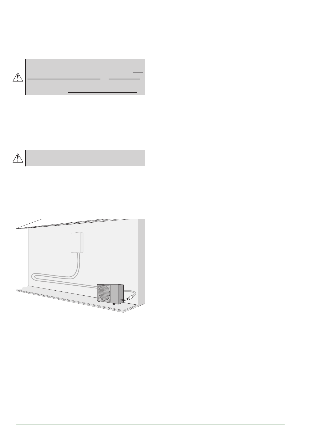
Installation
Installation of refrigeration
►
connections
Bend the pipes into position and make holes
for them through the oor or walls either with
their protective caps in place or after brazing.
Keep the protective caps in place or ends
brazed until the appliance is commissioned.
The outdoor unit must be connected to the hydraulic unit
only with brand new separately insulated copper
connections (refrigerant quality).
Maintain the same pipe diameters (g. 19).
Observe the maximum and minimum distances
between the hydraulic unit and the outdoor unit
(g. 19, page 24); the guarantee of performance and
the service lifespan of the system depend on this.
The minimum length of the refrigeration
connections for correct operation is 5 m.
The appliance's warranty will be void if it is operated
with refrigeration connections less than 5 m long
(tolerance +/- 10%).
If the refrigeration connections are exposed to
weathering or UV radiation and the insulation is not
resistant, protection must be provided.
g. 12 - Example of recommendation for layout of
refrigeration connections
- 16 -
Waterstage / Installation / 2011 - EN


D
Installation of the outdoor unit
►
Installation precautions
▼
The outdoor unit must only be installed
outside. If a shelter is required, it must have
broad openings on all 4 sides and installation
clearances must be observed.
• Choose the location of the appliance after discussion
with the client.
• We recommend choosing a site that is sunny but
sheltered from strong cold prevailing winds.
• The unit must be easily accessible for future installation
and maintenance work (page 20).
• Ensure that connections to the hydraulic unit can be
made easily.
• The outdoor unit is able to withstand bad weather but
avoid installing it in a position where it is likely to be
exposed to signicant dirt or owing water (under a
defective gutter for example).
• Water may ow out of the outdoor unit when it is
operating. Do not install the unit on a paved terrace;
choose a well-drained location (e.g. gravel or sand).
If installation is carried out in an area where the
temperature stays below 0°C for long periods, check
that the presence of ice does not present any danger.
A drainage pipe can also be connected to the outdoor
unit (see g. 14).
• Nothing should obstruct the air circulation through the
evaporator and out from the fan (g. 13).
• Keep the outdoor unit away from heat sources and
ammable products.
• Make sure that the unit does not disturb the
surrounding area or inhabitants (noise level, draught,
low temperature of the ejected air freezing the plants
in its path).
A ≥ 80 mm
B ≥ 100 mm
C ≥ 200 mm
D ≥ 300 mm
E ≥ 500 mm
F ≥ 600 mm
G ≥ 1000 mm
H ≥ 1500 mm
J ≥ 2000 mm
K ≥ 3000 mm
A
B
D
BB
E
H
G
B
G
G
B
A
B
B
B
D
B
B
H
B
B
D
E
E
H
B
J
F
G
g. 13 - Minimum installation clearances around the outdoor unit (all models)
- 18 -
B
B
H
B
B
H
E
B
B
E
Waterstage / Installation / 2011 - EN
H
K
F
• The surface on which the appliance is installed must:
- Be permeable (soil, gravel, etc.).
- Support its weight easily.
- Allow a solid fastening base,
- Not transmit any vibration to the dwelling. Anti-vibratory
blocks are available as an option.
• The wall bracket cannot be used where it is likely to
transmit vibrations. Installing the unit on the ground is
preferred.
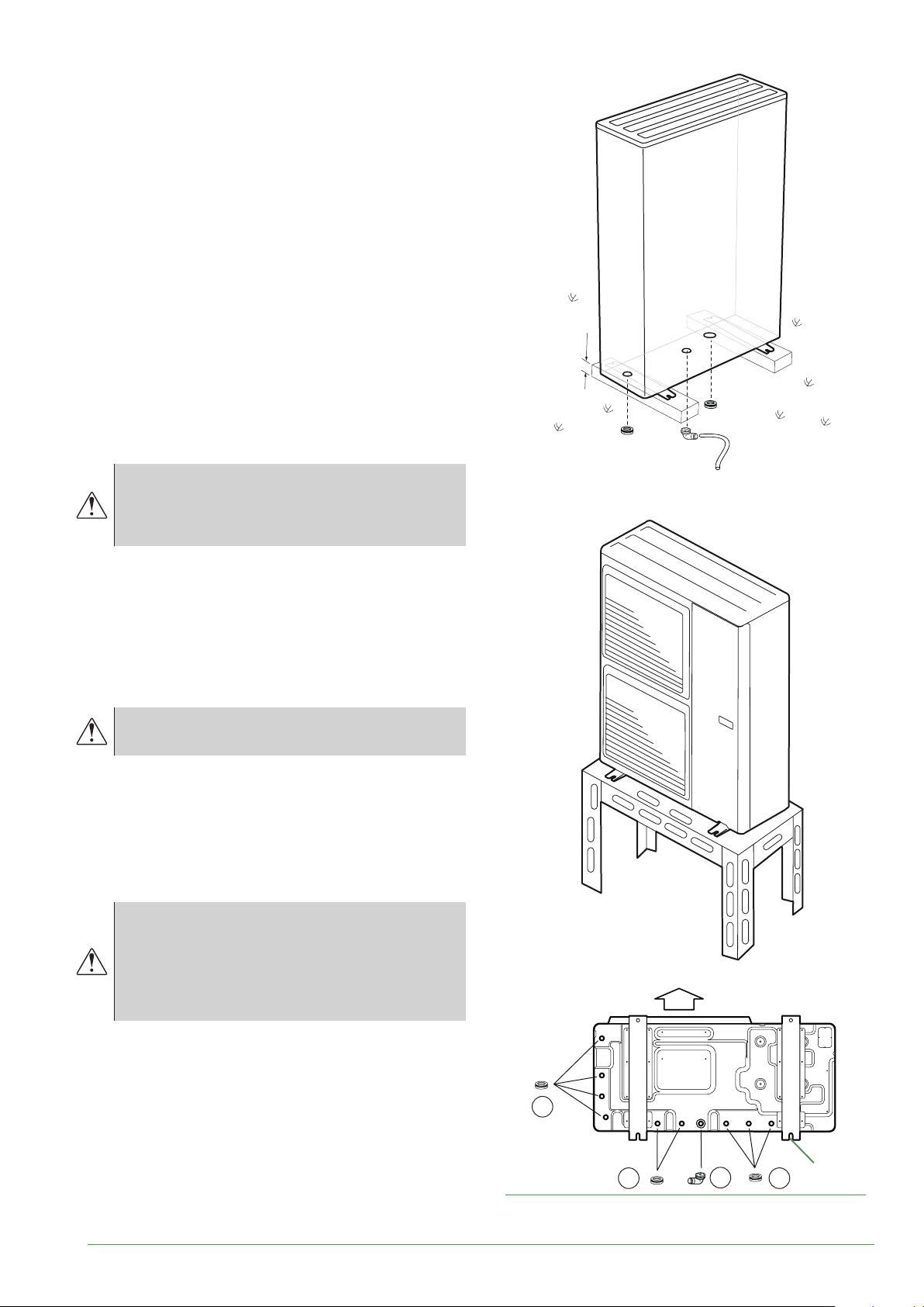
Positioning Outdoor Unit
▼
The outdoor unit must be raised at least 50 mm above
ground level. In areas prone to snow, this height should
be increased but should not exceed 1.5 m (gure 12).
- Fasten the outdoor unit by means of screws and
rubber tightening or toothed lock washers to prevent
them from coming loose.
H
In areas with heavy snowfall, if the intake and
outlet of the outdoor unit is blocked with snow,
heating may become dicult and a failure is
likely to occur.
Construct a canopy or place the unit on a high stand
(local conguration).
- Place the unit on a solid stand in order to minimise
impacts and vibrations.
- Do not place the unit directly on the ground as this will
cause problems.
Condensate drain pipe
▼
The outdoor unit can generate a large volume
of water (called condensate).
If the use of a drain pipe is necessary:
- Use the elbow provided (C) and connect a 16 mmdiameter hose for draining the condensate.
- Use the plug(s) provided (B) to block the opening of
the condensate drain pan.
Allow for the condensate to ow away under the force of
gravity (waste water, rain water, gravel bed).
If installation is carried out in an area where the
temperature stays below 0°C for long periods,
equip the drain pipe with trace heating to
avoid it icing up. Trace heating must heat not
only the drain pipe but also the bottom of the
appliance's condensate collection tank.
* In areas with heavy snowfall,
(H) must be higher than the average snow layer.
Air
Waterstage / Installation / 2011 - EN
B
4 holes
B
g. 14 - Installation of the outdoor unit evacuation of
condensates
C
(ø 12 mm)
B
- 19 -

Installation of the hydraulic unit
►
Installation precautions
▼
• Choose the location of the appliance after discussion
with the client.
• The installation space should comply with current
regulations.
• To facilitate maintenance and allow access to the
various parts, we recommend that you provide
sucient space all the way around the hydraulic unit.
350 mm
mini
300 mm
mini
1000 mm
- If the refrigeration connection is only performed at the
end of the installation, make sure that the refrigeration
circuit caps* remain in place and tight throughout the
installation.
* (Hydraulic unit side and outdoor unit side).
- After each maintenance operation on the refrigeration
circuit and before the nal connection, take care to
put the caps back in position to avoid any pollution
of the refrigeration circuit (sealing with adhesive is
prohibited).
Positioning the hydraulic unit
▼
- Fix the bracket S securely (4 screws and plugs) to a
strong, at wall (not a light partition) ensuring that it is
correctly levelled.
350 mm
min.
mini
538 mm
min.
mini
• In accordance with EN 378-1 -2017 standard
(Refrigerating systems and heat pumps - Safety and
environmental requirements), the system's hydraulic
unit and all refrigeration connections passing through
inhabited areas must comply with the minimum room
volume requirements shown hereafter.
The minimum volume of a room (in m3) is calculated
using the formula: "uid ll load" (in kg) / 0.39.
Alternatively, you must ensure that
- The location has natural ventilation through another
room where the combined volume of the two rooms
is greater than "liquid ll load" (in kg) / 0.39 kg/m³.
The opening between the two rooms must have a door
clearance of at least 1 cm.
- Or that the location is mechanically ventilated.
Be careful not to bring ammable gas
near the heat pump during installation,
in particular when brazing is required.
The appliances are not reproof and should
not therefore be installed in an explosive
environment.
- To avoid condensation inside the condenser, remove
the refrigeration circuit caps only when making the
refrigeration connections.
300 mm
mini
min.
118 mm
188 mm
418 mm
min.
mini
(S)
g. 15 - Mounting bracket
- Hook the appliance onto its bracket S.
Weight of the appliance (full of water) = 58Kg
- 20 -
Waterstage / Installation / 2011 - EN

10
9
19
C
7
7
C
C
C
6
5
B
B
(S)
4
3
2
1
A
A
TX20
8
19
TX20
g. 16 - Removing the casing
Waterstage / Installation / 2011 - EN
D
12
11
D
TX20
D
11
- 21 -
Refrigeration connections
This appliance uses refrigerant R410A.
Comply with the legislation on handling of refrigerants.
Rules and precautions
►
Connections must be made on the same day
the installation is lled with gas (see para.
"Filling the installation with gas", page 26).
• Minimum tools required
- Set of pressure gauges (Manifold) with hoses
exclusively designed for HFCs (Hydrouorocarbons).
- Vacuum gauge with isolation valves.
- Vacuum pump specically for HFCs (using a standard
vacuum pump is allowed if, and only if, it is tted with
a non-return valve on the suction side).
- Flaring tool, Pipe-cutter, Deburring tool, Spanners.
- Certied refrigerant leak detector (sensitivity 5g/year).
Using tools that have been in contact with
HCFCs (R22 for example) or CFCs is prohibited.
The manufacturer declines any liability with
regard to the warranty if the above instructions
are not observed.
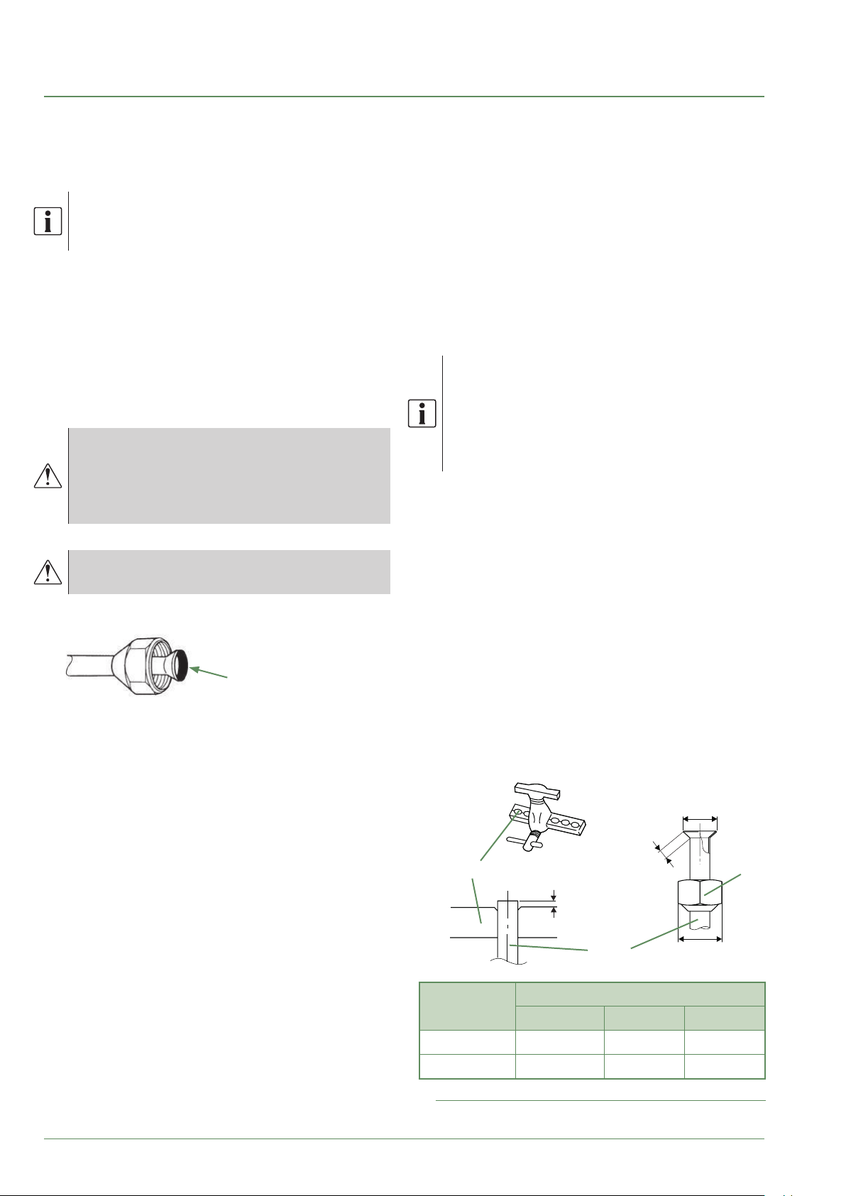
• Flared connections
Lubricating with mineral oil (for R12, R22)
is prohibited.
- Lubricate only with polyolester oil (POE). If POE is not
available, t without lubrication
Coat the ared surface
with POE refrigeration oil.
Do not use mineral oil.
described above, condensation will form on the
surface of the insulation material. Lastly, use insulating
sleeves whose thermal conductivity will be less than
or equal to 0.045 W/mK if the temperature is equal to
20°C. The insulation must be impermeable in order to
withstand the passage of vapour during the defrosting
cycles (glass wool is prohibited).
Shaping the refrigeration pipes
►
Bending
▼
The refrigeration pipes must be shaped only on a
bending machine or with a bending spring in order to
avoid any risk of crushing or breaking them.
Remove the insulation material from the section of
pipe to be bent.
Do not bend copper to an angle greater than 90°.
Never bend pipes more than 3 times in the
same place otherwise traces of fracturing may
appear (hardening of the metal).
Creating the arings
▼
- Cut the pipe to an appropriate length with a pipe-cutter
without damaging it.
- Carefully deburr it, holding the pipe pointing downward
to avoid introducing lings into the pipe.
- Remove the ared connection nut situated on the
valve to be connected and slide the pipe into the nut.
- Proceed to are it, letting the pipe protrude out of the
aring tool's tube.
- After aring, check the state of the working radius (L).
This must not present any scratches or signs of
fracturing. Also check the dimension (B).
• Brazing the refrigeration circuit (if necessary)
- Silver brazing (40% minimum recommended).
- Brazing only with dry nitrogen internal ux.
• Other remarks
- After each maintenance operation on the refrigeration
circuit and before nal connection, take care to put
the caps back in position to avoid any pollution of the
refrigeration circuit.
- To eliminate any lings getting into the pipes, use dry
nitrogen to avoid introducing any humidity that may
adversely aect the appliance's operation. In general,
take every precaution to avoid humidity penetrating
into the appliance.
- Proceed with thermal insulation of the gas and liquid
pipes to avoid any condensation. Use pipe insulators
resistant to temperatures over 90°C. In addition, if the
humidity level in areas where the refrigerant pipes are
installed is expected to exceed 70%, protect the pipes
with pipe insulators. Use an insulating material thicker
than 15mm if the humidity level reaches 70 ~ 80%,
and an insulating material thicker than 20mm if
the humidity exceeds 80%. If the recommended
thicknesses are not observed under the conditions
- 22 -
B
-0.4
L
C
C
Flaring tool
Pipe
Dimensions in mm
Pipe ø
L B 0/
9.52 (3/8") 2.5 to 2.7 13.2 22
15.88 (5/8") 2.9 to 3.1 19.7 29
g. 17 - Flaring of the ared connections
Waterstage / Installation / 2011 - EN
Nut
are

■ Outdoor unit
Front Side Lower
■ Hydraulic unit
Sortie dessousSortie avant Sortie latérale
g. 18 - Feeding through ared connections
Waterstage / Installation / 2011 - EN
- 23 -

HP model Waterstage SHP
gas liquid
Outside unit connections 5/8" 3/8"
Diameter (D1) 5/8" (D2) 3/8"
Refrigeration
connections
Maximum Height Difference
Hydraulic unit connections 5/8" 3/8"
1 Without additional lling of R410A.
2 Taking into account a possible additional ll of refrigerant R410A (see "Additional lling", page 28 ).
3 Outdoor unit over hydraulic unit and heating only / Other cases.
Minimum length (L) 5
Maximum length 1 (L) 15
Maximum length 2 (L) 30
2/3
(D) 25 / 15
Hydraulic
unit
Outdoor unit
Heat Pump
Hydraulic
Heat
Pump
mini
mini
min.
5m
5m
unit
DL
DL
"Liquid” valve
“Gas” valve
"Liquid" refrigerant
connection
D2 diameter
Flared nut
Flared nut
Flared nut
Flared nut
Outdoor unit
"Gas" refrigerant
connection
D1 diameter
g. 19 - Refrigeration connections (authorised diameters and lengths)
- 24 -
Waterstage / Installation / 2011 - EN
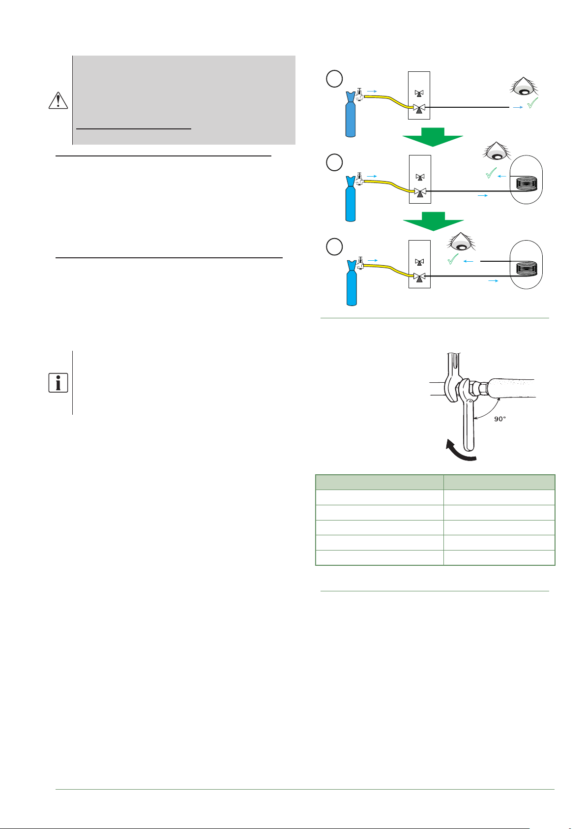
Checks and connection
►
The refrigeration circuit is very sensitive
to dust and humidity: check that the area
around the connection is clean and dry before
removing the plugs protecting the refrigeration
connectors.
Indicated blowing value: 6 bar for minimum
30 seconds for connection of 20 m.
Checking the gas connection (large diameter).
Connect the gas connection to the outdoor unit.
Blow dry nitrogen into the gas connection and inspect
its end:
- If water or impurities emerge, use a brand new
refrigeration connection.
Otherwise, proceed with aring and connect the
refrigeration connection to the outdoor unit immediately.
Checking the liquid connection (small diameter).
Connect the liquid connection to the hydraulic unit.
Blow nitrogen into the gas-condenser-liquid
connection system and inspect its end (outdoor unit side).
- If water or impurities emerge, use a brand new
refrigeration connection.
- Otherwise, proceed with aring and connect the
refrigeration connection to the outdoor unit immediately.
UE
1
Azote
Nitrogen
2
Azote
Nitrogen
3
Azote
Nitrogen
g. 21 - Checking refrigeration connections
OU
UE
OU
UE
OU
Gas
Liaison
connection
gaz
Liaison
Gas
connection
gaz
gaz
Gas
Liaison
Liquid
connection
liquide
MH*
HIU
MH*
HIU
Take particular care to position the tube
opposite its connector so as not to risk
damaging the threads. A properly aligned
connector can be attached easily by hand
without much force being required.
- Remove the plugs from the pipes and the refrigeration
connections.
- Warning! Avoid positioning the gas pipe in front of the
pump.
- Comply with the indicated tightening torques.
Holding spanner
Torque wrench
Designation Tightening torque
Flared nut 9.52 mm (3/8") 32 to 42 Nm
Flared nut 15.88 mm (5/8") 63 to 77 Nm
Plug (A) 3/8" 20 to 25 Nm
Plug (A) 5/8" 30 to 35 Nm
Plug (B) 3/8", 5/8" 10 to 12 Nm
Plug (A) and (B) : see g. 22, page 27.
g. 20 - Tightening torques
Waterstage / Installation / 2011 - EN
- 25 -
 Loading...