

Page 1
U0651601_2010_EN_1
24/06/2019
OPERATING INSTRUCTIONS
Air to Water Heat Pump
Split single service & Split integrated DHW type
For users. To be kept by the user for future reference.
EN
Page 2

Contents
Safety instructions 3
Overview of installation 4
Precautions and warnings about your installation ..4
Appliance end-of-life .......................5
Overview of the installation ..................5
Carrying out the installation 6
User interface, Room control unit (option) and
Room thermostat (option) ...................6
Display Description ........................8
Appliance start up .........................9
Quick start-up ............................9
Setting the time ..........................10
Structure of the "End user" control menu ......11
Parametering the setting ...................12
Information display .......................17
Details .................................18
Operation of the DHW system* ..............18
Selecting cooling mode* ...................18
Pilot wire* (if kit regulation extension AVS 55) ...18
Telephone modem* (if Regulation extension kit
AVS 55) ................................19
Conguring room control unit* (option) ........19
Maintenance 20
Regular checks ..........................20
Checking the outdoor unit ..................20
Hot water tank* ..........................20
- 2 -
Waterstage / OPERATING INSTRUCTIONS / 2010 - EN
Page 3

Safety instructions
Please comply with the following instructions in order to avoid any risk of injury or
inappropriate use of the appliance.
Commissioning
Do not switch the appliance ON until every lling operation has been performed
Do not attempt to install this appliance yourself. This heat pump must be installed by
qualied personnel holding a certicate of competence.
The installation must always be properly earthed and tted with a safety circuit breaker.
Do not change the power supply.
The appliances are not reproof and should not therefore be installed in an explosive
environment.
How to Use
This appliance can be used by children 8 years and above. Also persons with reduced
physical, sensory or mental capabilities, or lack of experience and knowledge, provided
they have been given supervision or instruction concerning use of the appliance in a safe
way and with the appliance. Cleaning and user maintenance shall not be made by children
without supervision.
Do not let children insert foreign bodies inside the propeller protection grate or climb onto
the roof of the outdoor unit. The ns of the air heat exchanger are extremely thin and can
cause cuts.
Nothing should obstruct the air circulation through the evaporator and out from the fan.
The outdoor unit must only be installed outside. If a shelter is required,it must have broad
openings on all 4 sides and installation clearances must be observed (see your installation
engineer).
Do not climb on top of the outdoor unit.
The room in which the unit is operating must be correctly ventilated in order to avoid any
shortage of oxygen in the event of a refrigerant gas leak.
If your installation location already meets safety standards, do not carry out any
modications (ventilation, exhaust evacuation, openings, etc.) without the advice of your
installation engineer.
Do not place any heat source under the remote control.
Maintenance
Do not try to repair the appliance yourself.
This appliance does not contain any components which can be repaired by the user.
Removing either of the covers can expose you to dangerous electrical voltages.
In any case, switching o the current is not sucient to protect you from any external
electrical shocks (condensers).
Do not open the outdoor unit or the hydraulic unit while they are in operation.
If you hear unusual noises, smell smoke or other odours coming from the appliance, turn
o the power and contact your installation engineer.
Before starting any cleaning, turn o the power to the appliance.
Do not use aggressive cleaning liquids or solvents to clean the body work.
Do not use a pressure hose to clean the outdoor unit. You may damage the air exchanger
and get water inside the electrical circuits.
Page 4

Overview of installation
Precautions and warnings about
►
your installation
Outdoor unit
▼
The outdoor unit contains the equipment that enables
the capture of energy from the surrounding air.
This unit was installed by your installer in a location
where it is able to operate with best performance.
Nothing should obstruct the air circulation through the
evaporator and out from the fan.
The water contained in the air may condense and ow
out of the outdoor unit. The outdoor unit can generate a
large volume of water called condensate.
In cold weather, this water freezes on contact with the
exchanger and must be regularly removed using the
defrosting cycles. The defrosting cycle is managed
automatically by the control system and can produce
steam emissions which are completely normal.
Hydraulic unit
▼
The hydraulic unit contains the appliance's control
system which manages the room temperature and the
production of domestic hot water.
The hydraulic unit is tted with an electrical backup*
or boiler connection* which intervenes to provide
additional heat during the coldest periods.
Settings
▼
Your installer has carefully adjusted your installation.
Do not change the settings without their consent.
If in doubt, do not hesitate to contact them.
Your heating system is controlled by adjustment in
relation to the outside temperature (temperature
control).
The installation of a room thermostat (option) makes it
possible to improve the operation of the control system
(inuence of the ambient temperature is taken into
account).
In order to ensure operation of the control system,
the room containing the thermostat must not also
contain a thermostatic valve. If this is the case, it must
be opened as far as possible.
A new underoor heating system must initially be
heated slowly to avoid any problems involving cracking.
Check with your installer that this initial heating
procedure has indeed been performed before freely
using your heating system.
An underoor heating system's signicant inertia
prevents sudden room temperature dierences.
However, this inertia implies a reaction time of around
several hours (approx 6 hours).
Any changes to the setting must be made slowly
and leave the installation sucient time to react. Any
exaggerated or abrupt adjustments to the settings
always result in signicant temperature uctuations
during the day.
Similarly if your dwelling has an underoor heating
system, do not reduce it or switch it o if you will be
absent for only short periods. The reheating period is
always quite long (approx 6 hours).
Do not use a room sensor in the area in question.
When hot water is required, the heat pump adapts its
priority to meet the request.
No heating is produced during the preparation of
domestic hot water.
The heat pump produces the domestic hot water
(DHW), which is then additionally heated, if required,
by the electrical backup.
To ensure a DHW setpoint over 45°C, the electrical
backup heating or boiler (boiler connection kit)* must
be left on.
The electrical backup allows the correct operation of the
anti-legionella cycles.
Radiators
▼
Underoor heating system
▼
Fan coils / dynamic radiators with an
▼
integrated control system
Domestic Hot Water (DHW)*
▼
* depending on conguration / option
- 4 -
Waterstage / OPERATING INSTRUCTIONS / 2010 - EN
Page 5

Appliance end-of-life
►
The appliances must be dismantled and recycled by a
specialised service. The appliances must not, under any
circumstances, be thrown out with household waste,
bulky waste or at a tip.
At the end of its service life, please contact your installer
or local representative to proceed with its dismantling
and recycling.
Overview of the installation
►
Your heat pump has been congured by your installation
engineer. It is made up of the following main parts:
- The outdoor unit, as its name suggests, is placed
outside your dwelling, and extracts energy from the
outside air.
- The hydraulic unit is located in your boiler room, cellar,
garage or even in your kitchen, and transfers energy to
the heating and domestic hot water circuits*.
- The outside sensor monitors the outside temperature.
Optional:
- Room sensor(s).
Heat pumps are systems which can be connected to
any type of low temperature distribution system and
the heat captured by the heat pump can be used in
dierent ways:
- Underoor heating system.
- Radiators.
- Domestic Hot Water (DHW)*.
Outside
sensor
Control options
Room thermostat
(wired or radio)
and/or
Remote control
(wired or radio)
Options depending
on hydraulic
or
congurations
connection kit
Menu
2
circuit kit
Boiler
Heating circuit
underoor heating
Radiators heating
circuit
Boiler
Hydraulic unit
Outdoor unit
g. 1 - Overview of complete installation conguration
Waterstage / OPERATING INSTRUCTIONS / 2010 - EN
* depending on conguration / option
- 5 -
Page 6
Carrying out the installation
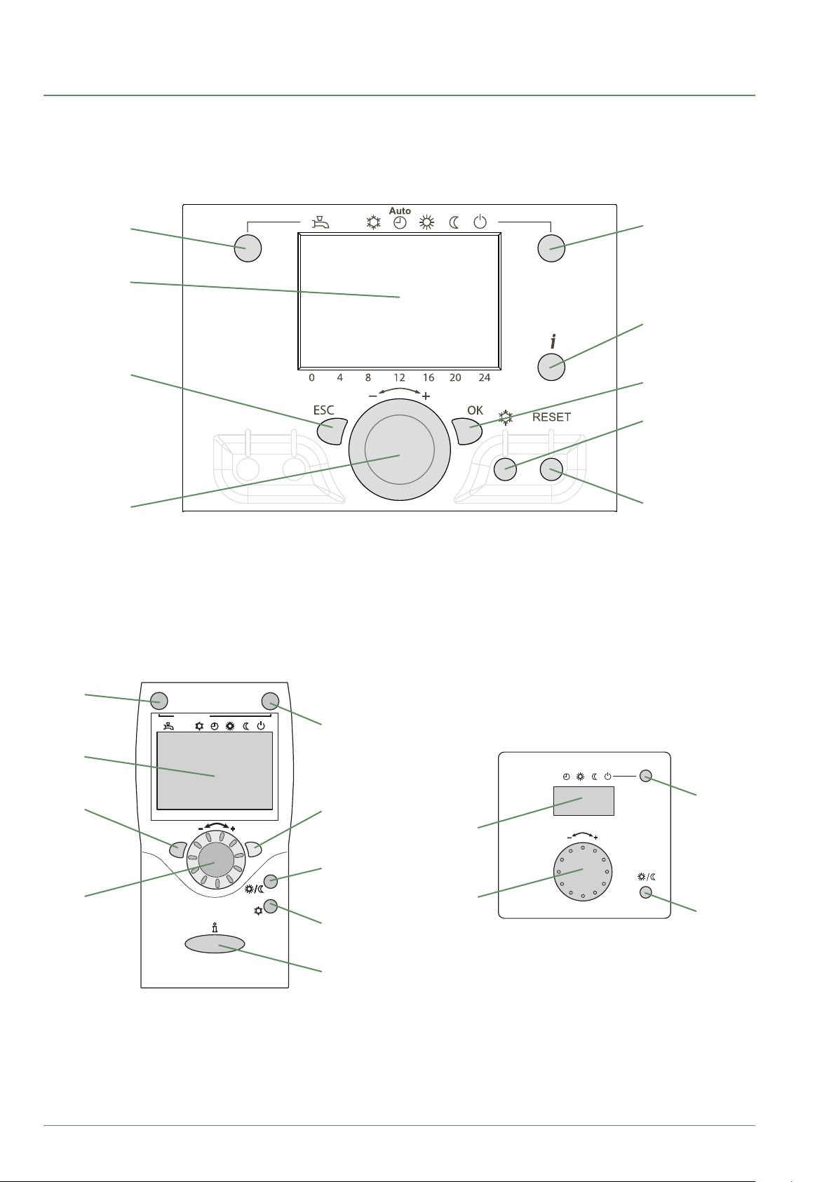
User interface, Room control unit (option) and Room thermostat (option)
►
1
5
2
6
3
7
8
4
9
1
Auto
2
5
Auto
5
3
0 4 8 12 16 20 24
ESC
OK
4
7
11
2
°C
10
11
8
6
- 6 -
Waterstage / OPERATING INSTRUCTIONS / 2010 - EN
Page 7
Ref. Functions - Denitions
Off
Auto
1 Selecting of the DHW operating mode
(Domestic hot water).
- If the installation is tted with a DHW tank.
- On: Production of DHW according to the time program.
- O: Preparing the domestic hot water for stopping with the anti-frost function
On
active.
- Manual start button: Hold down the DHW key for 3 seconds. Switch from
"reduced" to "comfort" until the next time the ECS timer switches over.
2 Digital display. - Operating control. Readout of the current temperature, of the heating mode
and of any faults .
- View the settings.
3 Exit "ESC". - Quit the menu.
4 Navigation and setting. - Selecting the menu.
- Setting parameters.
- Adjusting the ambient temperature setpoint.
5 Selecting the heating mode.
-
Heating operating according to the heating program
(Summer/winter mode switchover is automatic).
- Constant comfort temperature.
- Constant reduced temperature.
- Stand-by mode with anti-frost protection
(Provided that the heat pump's electrical power supply is not interrupted).
6 Information display. - Various data (see page 17).
- Reading error codes.
- Information concerning maintenance, special mode.
7 Conrm "OK". - Input into the selected menu.
- Conrmation of the parameter settings.
- Conrmation of the adjustment to the comfort temp. setting.
8 Selecting cooling mode. - If the installation is tted with the cooling kit:
- Cooling operating according to the heating program
(Summer/winter mode switchover is automatic).
9 RESET button
(Brief press)
- Reinitialising the parameters and cancelling error messages.
Do not use during normal operation.
10 Control knob. - Adjusting the ambient temperature setpoint.
11 Presence key. - Comfort / Reduced switchover.
Waterstage / OPERATING INSTRUCTIONS / 2010 - EN
- 7 -
Page 8

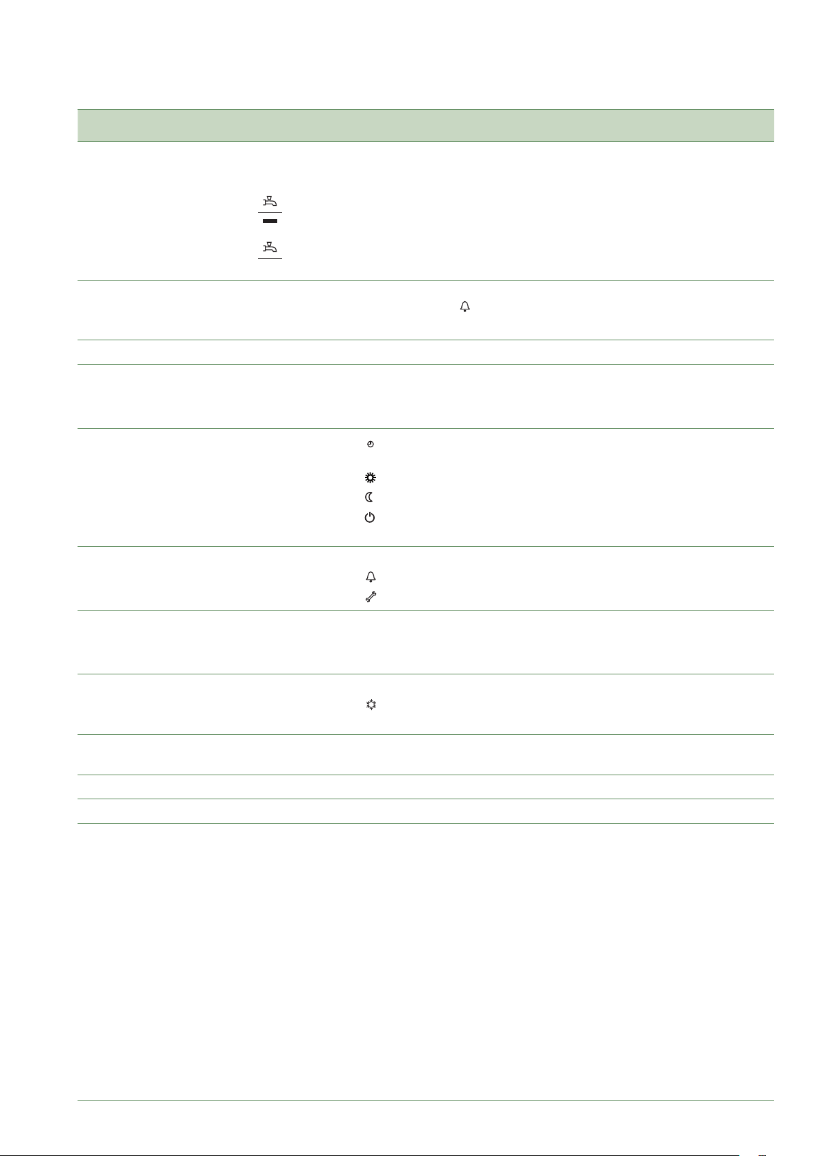
Display Description
►
Xxxxxxxxxxxxxxxxxxxxxxxxxxx
Xxxxxxxxxxxxxxxxxxxxxxxxxxx
Xxxxxxxxxxxxxxxxxxxxxxxxxxx
Symbols Denitions
- Heating mode active with reference
to the heating circuit*.
- Heating in comfort mode.
- Heating in reduced mode.
INFO
PROG
ECO
- Heating in "standby" mode
(freeze protection).
- Cooling mode active*.
- Holiday mode activated.
- Process in progress.
- Compressor operation.
- Burner operation*.
- Default message.
- Service / Special operation.
- Information level activated.
- Program activated.
- ECO mode activated
(Heating temporarily stopped).
g. 2 - Closing the display
- Hour /
temperature ambiante
temperature ambiante
temperature ambiante
* depending on conguration / option
Parameter number /
Setpoint value.
- Room temperature /
Setpoint value.
- Setpoint information /
Parameter Information.
- 8 -
Waterstage / OPERATING INSTRUCTIONS / 2010 - EN
Page 9

Appliance start up
►
• The installation and 1st start up of the appliance
must be done by a qualied installer. That person will
also give you instructions on starting and running the
appliance.
• Ensure that the installation is fully lled with water
and has been correctly bled and that there is a
sucient pressure of 1.5 to 2 bars on the manometer
(ref. 2, g. 3).
• Close the installation's main circuit breaker.
In winter, so that the compressor can be
preheated, close the installation's main circuit
breaker (outdoor unit's power supply) some
hours before pressing the on/o button.
Quick start-up
►
Once your installer has started your installation for the
rst time:
• Engage the start/stop switch.
During the regulator initialisation phase, the
display shows all the symbols and then "Data,
update" and then "State heat pump".
• Select the "AUTO" heating mode (g. 4).
• Select the DHW mode (g. 4).
• Adjust the date and time if necessary (g. 5)).
Press OK
1. User interface
2. Manometer (installation hydraulic pressure)
3. Start/stop switch
g. 3 - Start-up
_______________
Time and date
Operator section
1
2
Time and date
Hours / minutes
Select menu
hour and date
Press OK
Select one of the
lines :
hour / minutes
or day / month
or years
Press OK
3
Make all the
settings
Time and date
Hours / minutes
Press OK to
conrm each
setting
g. 4 - Selecting the heating mode AUTO
and Select the DHW mode
Waterstage / OPERATING INSTRUCTIONS / 2010 - EN
Press heating mode key to
return to basic display
g. 5 - Setting the time and the date
- 9 -
Page 10

Setting the time
►
Keys Display example Description
1
AUTO
Room temperature
4812 16 20 24
0
Basic display
If the basic display is not shown,
press ESC to return to it
Press OK to conrm.
2
AUTO
Turn the knob
Select menu hour and date
Time and date
Operator section
4812 16 20 24
0
Press OK to conrm.
3
AUTO
Turn the knob
Time and date
Hours / minutes
4812 16 20 24
0
Select line 1 Hours / minutes
Press OK to conrm.
4
Time and date
Hours / minutes
0
AUTO
4812 16 20 24
The hour display ashes
Turn the knob to set the time
Press OK to conrm.
g. 6 -
- 10 -
5
Time and date
Hours / minutes
0
AUTO
4812 16 20 24
The minutes display ashes
Turn the knob to set the minutes
Press OK to conrm.
6
AUTO
The setting are recorded
Turn the knob to make other settings
Time and date
Hours / minutes
04812162024
or
Press heating mode key to return to
basic display.
Waterstage / OPERATING INSTRUCTIONS / 2010 - EN
Page 11

Structure of the "End user" control menu
►
Basic
display
Brief
press
End user
Time of day and date
Operator section Language
Time prog heating circuit 1
Time prog heating circuit 2
Time program 4/DHW
Commissioning Engineer OEM
Hours / minutes
Day / Month
Year
Pre-selection
1st phase on
1st phase off
2nd phase on
2nd phase off
3rd phase on
3rd phase off
Copy
Default values
20
500
501
502
503
504
505
506
515
516
1
2
3
Hours
1 ...24h
Minutes
English, German...
Mon-Sun
Mon-Fri
Sat-Sun
Monday
Tuesday
…
Sunday
0...60 min
Holidays heating circuit 1
Holidays heating circuit 2
Heating circuit 1
Heating circuit 2
Domestic hot water
Fault Reset HP
Service/special operation
Diagnostics heat generation
Diagnostics consumers Outdside temp.
Pre-selection
1st phase on
1st phase off
Operation level
Comfort setpoint Reduced temp...
Reduced setpoint
Frost protect. setpoint
Nominal setpoint
Emergency operation
Return temp HP
Flow temp HP
Compressor modulation
Reset outside temp min
Reset outside temp max
...
Swimming pool temp.
641
642
643
648
710
712
714
1610
6711
7141
8410
8412
8413
8700
8701
8702
...
8900
Period 1
Period 2
...
Period 8
28 °C
Temp. frost protect... comfort
4°C...
No, Yes
Off, On
reduced temp.
Reduced temp...
Off, On
65 °C
g. 7 -
Waterstage / OPERATING INSTRUCTIONS / 2010 - EN
- 11 -
Page 12

Parametering the setting
►
General
▼
Only the parameters accessible to levels:
End user
... are described in this document.
The parameters accessible at level:
Commissioning
Engineer
… are described in the document reserved for these
professional specialists. Do not make any modications
to these parameters without advice from these
professional specialists. Incorrect use of any kind
may result in serious malfunctioning.
Setting parameters
▼
With the screen on basic display.
- Press OK.
Once in "End user" level.
- Scroll the menu list.
- Choose the desired menu.
- Scroll the function lines.
- Choose the desired line.
- Adjust the parameter.
- Check the setting by pressing OK.
- To return the menu, press ESC.
If no setting is made for 8 minutes, the screen returns
automatically to the basic display.
OK
Brief
press
End user
OK OK OK
Time and date Hours / minutes 1 Hours 1...24 h
User interface Day / Month 2 Minutes 0...60 min
CC1 time program Year 3
...
List of "End user" settings
▼
Line Function
Time of day and date
1 Hours / Minutes 00:00... 23:59 1
Setting range
or display
Setting
increment
Basic
setting
2 Day / Month 01.01... 31.12 1
3 Year 1900... 2099 1
Operator Section
20 Language English, Français, Italiano,
Nederlands...
- 12 -
Waterstage / OPERATING INSTRUCTIONS / 2010 - EN
English
Page 13

Line Function
Time program heating / cooling, circuit 1
Setting range
or display
Setting
increment
Basic
setting
500 Pre-selection (Day / Week) Mon-Sun, Mon-Fri, Sat-Sun,
Monday, Tuesday, …
501 1st phase On (start) 00:00... --:-- 10 min 6:00
502 1st phase O (end) 00:00... --:-- 10 min 22:00
503 2nd phase On (start) 00:00... --:-- 10 min --:--
504 2nd phase O (end) 00:00... --:-- 10 min --:--
505 3rd phase On (start) 00:00... --:-- 10 min --:--
506 3rd phase O (end) 00:00... --:-- 10 min --:--
516 Default values, Circuit 1 No, Yes No
Yes + OK: The default values memorised in the regulator replace and cancel the customised heating programs.
Your customised settings are therefore lost.
Time program heating / cooling, circuit 2
Only with the 2nd circuit kit option.
520 Pre-selection (Day / Week) Mon-Sun, Mon-Fri, Sat-Sun,
Monday, Tuesday, …
521 1st phase On (start) 00:00... --:-- 10 min 6:00
522 1st phase O (end) 00:00... --:-- 10 min 22:00
523 2nd phase On (start) 00:00... --:-- 10 min --:--
524 2nd phase O (end) 00:00... --:-- 10 min --:--
Mon-Sun
Mon-Sun
525 3rd phase On (start) 00:00... --:-- 10 min --:--
526 3rd phase O (end) 00:00... --:-- 10 min --:--
536 Default values, Circuit 2 No, Yes No
Yes + OK: The default values memorised in the regulator replace and cancel the customised heating programs.
Your customised settings are therefore lost.
Time program 4 / DHW
If the installation is tted with the DHW kit.
560 Pre-selection (Day / Week) Mon-Sun, Mon-Fri, Sat-Sun,
Monday, Tuesday, …
561 1st phase On (start) 00:00... --:-- 10 min 00:00
562 1st phase O (end) 00:00... --:-- 10 min 05:00
563 2nd phase On (start) 00:00... --:-- 10 min 14:30
564 2nd phase O (end) 00:00... --:-- 10 min 17:00
565 3rd phase On (start) 00:00... --:-- 10 min --:--
566 3rd phase O (end) 00:00... --:-- 10 min --:--
576 Default values No, Yes No
Yes + OK: The default values memorised in the regulator replace and cancel the customised heating programs.
Your customised settings are therefore lost.
Holidays, heating circuit 1 (For the Holiday program is active, the heating mode should be on AUTO).
Mon-Sun
641 Preselection Period 1 to 8 Period 1
642 Period Start (Day / Month) 01.01... 31.12 1
643 Period End (Day / Month) 01.01... 31.12 1
648 Operating level Frost protection, Reduced Frost
protection
Waterstage / OPERATING INSTRUCTIONS / 2010 - EN
- 13 -
Page 14

Line Function
Holidays, heating circuit 2 (For the Holiday program is active, the heating mode should be on AUTO).
If the installation consists of 2 heating circuits (Only with the 2nd circuit kit option).
651 Preselection Period 1 to 8 Period 1
652 Period Start (Day / Month) 01.01... 31.12 1
653 Period End (Day / Month) 01.01... 31.12 1
Setting range
or display
Setting
increment
Basic
setting
658 Operating level Frost protection, Reduced Frost
Heating adjustment, circuit 1
710 Comfort setpoint Reduced setpoint…
Comfort setpoint maximum
712 Reduced setpoint Frost protection setpoint…
Comfort setpoint
714 Frost protection setpoint 4 °C… Reduced setpoint 0,5 °C 8 °C
Cooling circuit 1
If the installation is tted with the cooling kit (Only with the cooling kit option).
901 Operating mode Protection, Automatic, Reduced,
Comfort
902 Comfort cooling setpoint 17... 40 °C 0,5 °C 24 °C
903 Reduced setpoint 5... 40°C 26 °C
Heating adjustment, Circuit 2
Only with the 2nd circuit kit option (If the installation consists of 2 heating circuits).
1010 Comfort setpoint Reduced setpoint…
Comfort setpoint maximum
1012 Reduced setpoint Frost protection setpoint…
Comfort setpoint
0,5 °C 20 °C
0,5 °C 19 °C
0,5 °C 20 °C
0,5 °C 19 °C
protection
Protection
1014 Frost protection setpoint 4 °C… Reduced setpoint 0,5 °C 8 °C
Cooling circuit 2
If the installation is tted with the cooling kit (Only with the cooling kit option).
1201 Operating mode Protection, Automatic, Reduced,
1202 Comfort cooling setpoint 17... 40 °C 0,5 °C 24 °C
1203 Reduced setpoint 5... 40°C 26 °C
Domestic hot water
If the installation is tted with the DHW kit.
1600 Operating mode O, On, Eco On
1610 Nominal setpoint Reduced setpoint (line 1612)…
The backup electrical system is required to reach this level.
1612 Reduced setting 8 °C...
Swimming pool (Only with swimming pool kit option)
2055 Setpoint solar heating 8... 80 °C 26 °C
2056 Setpoint source heating 8... 35 °C 22 °C
Comfort
65 °C
Nominal setting (line 1610)
1 55 °C
1 40 °C
Protection
- 14 -
Waterstage / OPERATING INSTRUCTIONS / 2010 - EN
Page 15

Line Function
Energy meter
3095 --> 3110 : Not used
3113 Energy brought in Kwh --
Cumulation of total consumed electrical energy.
Electrical energy consumed = Electrical energy absorbed by outdoor unit + electric energy absorbed by the heating
electrical backup and / or DHW electrical backup (if installed).
3121 --> 3123 : Not used
3124 Energy brought in heating 1 (N - 1) Kwh --
3125 Energy brought in DHW 1 Kwh --
3126 Energy brought in cooling 1 Kwh --
3128 --> 3130 : Not used
3131 Energy brought in heating 2 (N - 2) Kwh --
3132 Energy brought in DHW 2 Kwh --
3133 Energy brought in cooling 2 Kwh --
3135 --> 3137 : Not used
3138 Energy brought in heating 3 (N - 3) Kwh --
Setting range
or display
Setting
increment
Basic
setting
3139 Energy brought in DHW 3 Kwh --
3140 Energy brought in cooling 3 Kwh --
3142 --> 3144 : Not used
3145 Energy brought in heating 4 (N - 4) Kwh --
3146 Energy brought in DHW 4 Kwh --
3147 Energy brought in cooling 4 Kwh --
3149 --> 3151 : Not used
3152 Energy brought in heating 5 (N - 5) Kwh --
3153 Energy brought in DHW 5 Kwh --
3154 Energy brought in cooling 5 Kwh --
3156 --> 3158 : Not used
3159 Energy brought in heating 6 (N - 6) Kwh --
3160 Energy brought in DHW 6 Kwh --
3161 Energy brought in cooling 6 Kwh --
3163 --> 3165 : Not used
3166 Energy brought in heating 7 (N - 7) Kwh --
3167 Energy brought in DHW 7 Kwh --
3168 Energy brought in cooling 7 Kwh --
3170 --> 3172 : Not used
3173 Energy brought in heating 8 (N - 8) Kwh --
3174 Energy brought in DHW 8 Kwh --
3175 Energy brought in cooling 8 Kwh --
3177 --> 3179 : Not used
Waterstage / OPERATING INSTRUCTIONS / 2010 - EN
- 15 -
Page 16

Line Function
3180 Energy brought in heating 9 (N - 9) Kwh --
3181 Energy brought in DHW 9 Kwh --
3182 Energy brought in cooling 9 Kwh --
3184 --> 3186 : Not used
3187 Energy brought in heating 10 (N - 10) Kwh --
3188 Energy brought in DHW 10 Kwh --
3189 Energy brought in cooling 10 Kwh --
390 --> 3267 : Not used
Error
6710 Reset Defaut relais No, Yes No
6711 Reset HP No, Yes No
Maintenance / special regime
7141 Emergency operation O, On O
O: Heat pump functions normally (with boosters if necessary).
On: Heat pump uses the electric boost system or the boiler connection.
Use the “On” position only in Assist mode or Test mode: may result in high power bills.
Setting range
or display
Setting
increment
Basic
setting
Generator diagnosis
8410 Return temp HP 0... 140 °C --
Setpoint (ow) HP --
8412 Flow temp HP 0... 140 °C --
Setpoint (ow) HP --
8413 Compressor modulation 0... 100% --
Diagnostics consumers
8700 Outdoor temperature -50... 50 °C --
8701 Outdoor temp min
Reset ? (no, yes)
8702 Outdoor temp max
Reset ? (no, yes)
8740 Room temperature 1 0... 50 °C --
Room setting 1 20 °C
8743 Flow temperature 1 0... 140 °C --
Flow temperature setpoint 1 --
8756 Cooling ow temperature 1 0... 140 °C --
Cooling ow temperature setpoint 1 --
-50... 50 °C 50 °C
-50... 50 °C -50 °C
8830 DHW (domestic hot water) temperature 0... 140 °C --
DHW temperature setpoint 50 °C
- 16 -
Waterstage / OPERATING INSTRUCTIONS / 2010 - EN
Page 17

Information display
►
Various data can be displayed by pressing the info
button .
Depending on the type of unit, conguration and
operating state, some of the info lines listed below may
not appear.
- Possible error messages: The display shows the "Bell"
symbol .
Consult your heating technician.
- Service messages ; Special mode messages:
The display shows the “Key” symbol .
Consult your heating technician.
- Various data (see below).
Designation Line
Floor drying current setpoint . -
Current drying day. -
Terminated drying days. -
State heat pump. 8006
State supplementary source. 8022
State DHW. 8003
State swimming pool. 8011
State heating circuit 1. 8000
State heating circuit 2. 8001
State cooling circuit 1. 8004
Outdoor temperature. 8700
Room temperature 1.
Room setpoint 1.
Flow temperature 1.
Flow temperature setpoint1.
Room temperature 2.
Room setpoint 2.
Flow temperature 2.
Flow temperature setpoint 2.
DHW (domestic hot water) temperature. 8830
Heat pump return temperature.
Setpoint (return) HP.
Heat pump ow temperature.
Setpoint (ow) HP.
Swimming pool temperature.
Swimming pool temperature setpoint.
Minimum remaining stop time for compressor 1. -
Minimum remaining running time for compressor 1. -
8740
8743
8770
8773
8410
8412
8900
Waterstage / OPERATING INSTRUCTIONS / 2010 - EN
- 17 -
Page 18

Details
►
If the electrical power supply has been cut o while
the heat pump is operating (electrical power failure or
unprogrammed pressing of the on/o switch on the
hydraulic unit) the display will show error 370 when
the appliance restarts. Do not be concerned, the
communication between the outdoor and hydraulic unit
will re-establish itself in a few moments.
Operation of the DHW system*
►
The key enables you to switch the DHW (domestic hot
water) mode on and o. The selection is shown by a
bar, which appears under the corresponding symbol.
Manual activation: Hold down the DHW key for 3 seconds
(Switch from "reduced" to "nominal" until the next time
the DHW timer switches over).
To ensure a DHW setting over 45°C, the electrical backup heating or the boiler must be left on.
In order to optimise operation of the DHW, it is possible to:
- Program the timer settings (parameters 560 to 576),
- Adjust the comfort temperature set point (parameter 1610),
- Adjust the reduced temperature set point (parameter 1612).
g. 8 - Select the DHW mode
Brief
press
g. 9 - Information key
Details of any error
Operating values
...
Press the info key to obtain the details on the DHW
(temperature setting operation).
Selecting cooling mode*
►
If the installation is tted with the cooling kit.
The key activates and deactivates cooling mode.
Pilot wire* (if kit regulation
►
extension AVS 55)
It's possible to order up to 15 electric heaters via output
"pilot wire".
The "pilot wire" handles only the hourly operation
of electric heaters (comfort mode / reduced mode
commutation and Frost protection mode).
The comfort temperature setting should be done
directly on the electric heater(s). The "pilot wire" does
not handle the temperature of the electric heaters.
Refer to the manual supplied with the electric heater(s).
Put the electric heaters on "PROG" mode or "AUTO"
mode for piloting by the regulation board.
The dierence between the comfort temperature and
the reduced temperature is from 3.5°C.
Frost protection temperature is set directly on the
electric heaters. Refer to the manual supplied with the
electric heater(s).
In the absence of signal, electric heaters operating in
comfort mode.
g. 10 - Selecting cooling mode
g. 11 - Selecting the frost protection
* depending on conguration / option
- 18 -
Waterstage / OPERATING INSTRUCTIONS / 2010 - EN
Page 19

Telephone modem* (if Regulation
►
extension kit AVS 55)
It is possible to command the switching of the heating
mode to the "freeze" protection mode / reduced
(and vise versa) on the heat pump using a modem
contact.
The telephone command switches the current heat
pump settings to "freeze" protection mode / reduced
(and vise versa). In accordance with the setting, any
temperature requests from the heating circuits and the
DHW are ignored or activated.
The "freeze" protection mode / reduced must not be
selected on the heat pump and/or the remote control.
See with your installer.
Conguring room control unit*
►
(option)
In the event that the room control unit (see page 6),
is used, on start-up, after initialising for around
3 minutes, the language needs setting:
- Press OK.
- Choose menu "Operator section".
- Choose language "Language" English.
Waterstage / OPERATING INSTRUCTIONS / 2010 - EN
- 19 -
Page 20

Maintenance
In order to ensure that your appliance operates correctly
for many years, the maintenance operations described
below are required at the start of each heating season.
They are generally carried out as part of a maintenance
contract.
Regular checks
►
- Check the water pressure in the heating circuit
regularly (refer to the installer's recommended
pressure - between 1 and 2 bar)
- If a lling operation and a pressure increase are
required, check what type of uid was used initially
(when in doubt, contact your installer).
- If frequent rells are required it is absolutely essential
that you check for any leaks.
The frequent addition of water risks scaling the
exchanger and aects its performance and lifespan.
Checking the outdoor unit
►
Remove any dust from the exchanger, if necessary,
while making sure not to damage the blades.
Check that there is nothing blocking the air ow.
• Checking the refrigeration circuit
If the amount of refrigerant in the system exceeds 2kg
(models > 10 kW), the refrigeration circuit must be
checked annually by an approved engineer (they must
have a certicate of competence for the handling of
refrigerants).
Consult your heating technician.
Hot water tank*
►
Maintenance on the tank must be carried out annually
(frequency may vary according to water hardness).
Consult your heating technician.
* depending on conguration / option
- 20 -
Waterstage / OPERATING INSTRUCTIONS / 2010 - EN
Page 21

LED O:
The circulation pump is not working, no power supply.
Green LED On:
The circulation pump is operating normally.
Green LED ashing:
Venting mode in operation (10 minutes).
Red/green LED ashing:
Operating error with automatic restart.
Red LED ashing:
Operating error, consult your heating engineer.
g. 12 - Operating signals of the HP circulation pump
Waterstage / OPERATING INSTRUCTIONS / 2010 - EN
- 21 -
 Loading...