

Page 1
查询VSB-100MB供应商
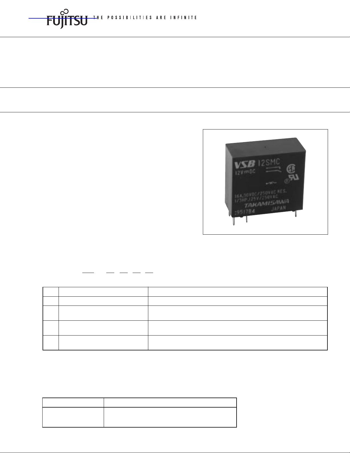
POWER RELAY
1 POLE—16 A (HEAVY POWER CONTROL)
VSB SERIES
■ FEATURES
● All or nothing relay
● UL, CSA, VDE, SEV, FIMKO, SEMKO, IMQ, ÖVE, BSI
recognized
● Working class: C
● Type of service: continuous duty
● Heavy duty 16 A miniature power relay
● UL Class B (130°C) insulation
● High isolation in small package
—Insulation distance: 8 mm
—Dielectric strength: 5,000 VAC
(between coil and contacts)
—Surge strength: 10,000 V
● Low power consumption and high sensitivity type
available VSB-S)
● Plastic sealed (with tape) type available
■ ORDERING INFORMATION
[Example]
(a) Series Name VSB: VSB Series
(b) Nominal Voltage Refer to the COIL DATA CHART
(c) Coil Type Nil : Standard type
(d) Contact Arrangement M : 1 form A (SPST-NO)
(e) Enclosure B : Flux free type
Note: Actual marking omits the hyphen (-) of (*)
VSB – 12 S T B
(a) (*) (b) (c) (d) (e)
S : High sensitivity type
T : 1 form C (SPDT)
C : Plastic sealed type (with tape)
■ SAFETY STANDARD AND FILE NUMBERS
UL508, 873 (File No. E56140, E108658)
C22.2 No. 14 (File No. LR35579)
VDE0435, 0631, 0700 (File No. 11039-4940-0005/30K)
Nominal voltage Contact rating
3 to 100 VDC 1/3 HP 125 VAC/250 VAC
16 A 30 VDC/250 VAC resistive
Pilot duty C 150
Page 2
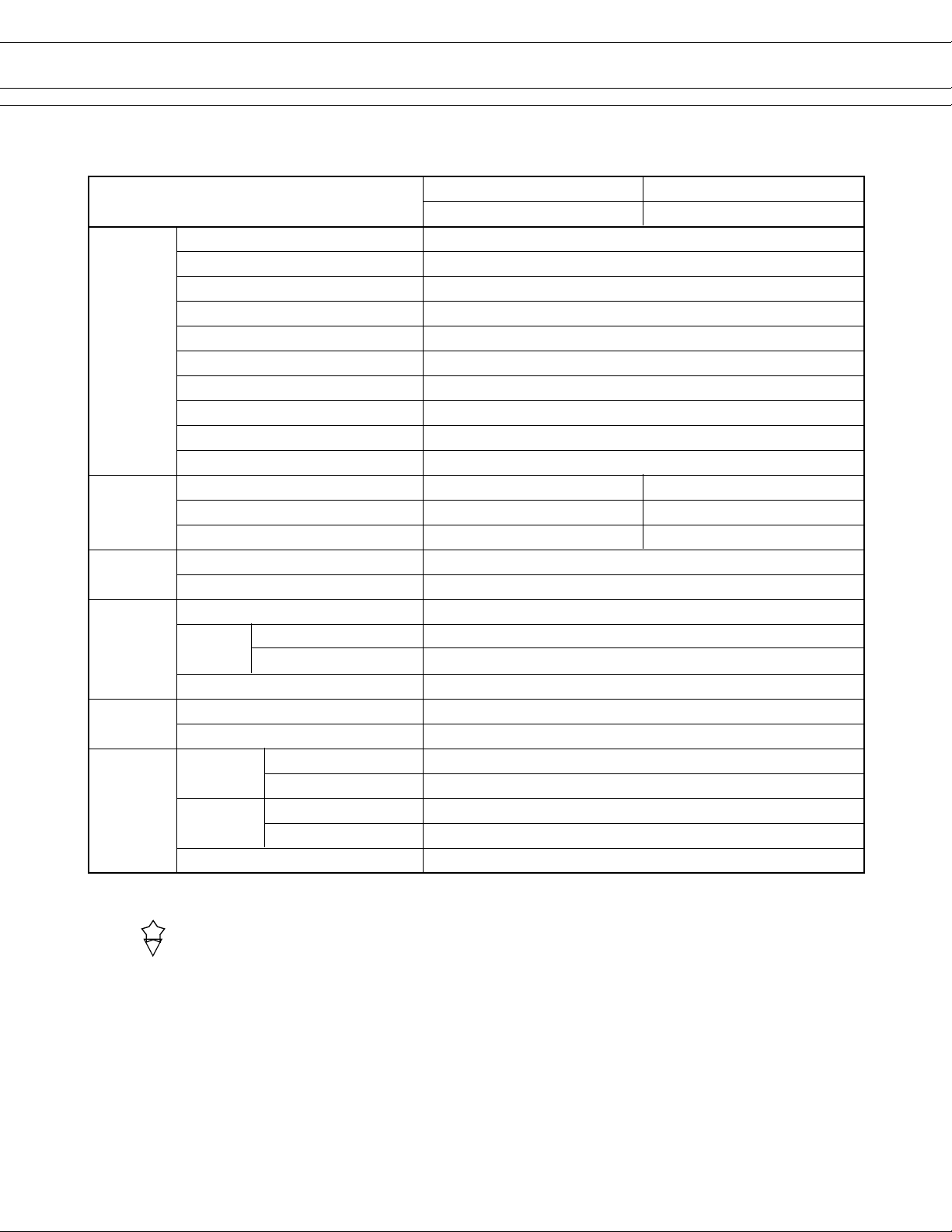
■ SPECIFICATIONS
VSB SERIES
Item
Standard Type High Sensitve Type
VSB-( ) VSB-( )-S
Contact Arrangement 1 form A (SPST-NO) or 1 form C (SPDT)
Material Silver alloy
Style Single
Resistance (initial) Maximum 200 mΩ (at 1 A 6 VDC)
Rating (resistive) 16 A 250 VAC/30 VDC
Maximum Carrying Current 16 A
Maximum Switching Power 4,000 VA, 480 W
Maximum Switching Voltage 380 VAC, 150 VDC
Maximum Switching Current 16 A
Minimum Switching Load*
1
100 mA 5 VDC
Coil Nominal Power (at 20°C) 0.7 to 0.75 W 0.53 W
Nominal Voltage (at 20°C) 0.35 to 0.37 W 0.26 W
Operating Temperature –40°C to +65°C (no frost) –40°C to +75°C (no frost)
Time Value Operate (at nominal voltage) Maximum 15 ms
Release (at nominal voltage) Maximum 10 ms
Insulation Resistance (at 500 VDC) Minimum 1,000 MΩ
Dielectric
Strength
Surge Strength*
between open contacts 1,000 VAC 1 minute
between coil and contacts
3
*2 5,000 VAC 1 minute
10,000 V (at 1.2 x 50µs)
Life Mechanical 2 × 10⁷ operations minimum
Electrical 1 × 10⁵ operations minimum (contact rating)
Other
Vibration
Resistance
Endurance 10 to 55 Hz (double amplitude of 1.5 mm)
Misoperation 10 to 55 Hz (double amplitude of 1.5 mm)
Misoperation 100 m/s2 (11 ±1 ms)
Resistance
Endurance 1,000 m/s
2
(6 ±1 ms)
Weight Approximately 18 g
*1Minimum switching loads mentioned above are reference values. Please perform the confirmation test with the actual load
before production since reference values may vary according to switching frequencies, environmental conditions and
expected reliability levels.
2
*
3
*
IMQ
IMQ
2
0
2
Page 3

■ COIL DATA CHART
VSB SERIES
MODEL
VSB- 3 ( ) ( ) 3 VDC 12.5 Ω 2.1 VDC 0.3 VDC 0.72 W
VSB- 5 ( ) ( ) 5 VDC 36 Ω 3.5 VDC 0.5 VDC 0.70 W
VSB- 6 ( ) ( ) 6 VDC 50 Ω 4.2 VDC 0.6 VDC 0.72 W
VSB- 9 ( ) ( ) 9 VDC 115 Ω 6.3 VDC 0.9 VDC 0.70 W
VSB- 12 ( ) ( ) 12 VDC 200 Ω 8.4 VDC 1.2 VDC 0.72 W
VSB- 14 ( ) ( ) 14 VDC 280 Ω 9.8 VDC 1.4 VDC 0.70 W
VSB- 18 ( ) ( ) 18 VDC 460 Ω 12.6 VDC 1.8 VDC 0.70 W
VSB- 24 ( ) ( ) 24 VDC 820 Ω 16.8 VDC 2.4 VDC 0.70 W
Standard TypeHigh Sensitivity Type
VSB- 36 ( ) ( ) 36 VDC 1,850 Ω 25.2 VDC 3.6 VDC 0.70 W
VSB- 48 ( ) ( ) 48 VDC 3,300 Ω 33.6 VDC 4.8 VDC 0.70 W
VSB- 60 ( ) ( ) 60 VDC 5,100 Ω 42.0 VDC 6.0 VDC 0.70 W
VSB-100 ( ) ( ) 100 VDC 13,400 Ω 70.0 VDC 10.0 VDC 0.75 W
VSB- 3S ( ) ( ) 3 VDC 17 Ω 2.1 VDC 0.3 VDC 0.53 W
VSB- 5S ( ) ( ) 5 VDC 47 Ω 3.5 VDC 0.5 VDC 0.53 W
VSB- 6S ( ) ( ) 6 VDC 68 Ω 4.2 VDC 0.6 VDC 0.53 W
VSB- 9S ( ) ( ) 9 VDC 155 Ω 6.3 VDC 0.9 VDC 0.53 W
VSB- 12S ( ) ( ) 12 VDC 270 Ω 8.4 VDC 1.2 VDC 0.53 W
VSB- 14S ( ) ( ) 14 VDC 370 Ω 9.8 VDC 1.4 VDC 0.53 W
VSB- 18S ( ) ( ) 18 VDC 610 Ω 12.6 VDC 1.8 VDC 0.53 W
VSB- 24S ( ) ( ) 24 VDC 1,100 Ω 16.8 VDC 2.4 VDC 0.53 W
VSB- 36S ( ) ( ) 36 VDC 2,450 Ω 25.2 VDC 3.6 VDC 0.53 W
VSB- 48S ( ) ( ) 48 VDC 4,400 Ω 33.6 VDC 4.8 VDC 0.53 W
VSB- 60S ( ) ( ) 60 VDC 6,800 Ω 42.0 VDC 6.0 VDC 0.53 W
VSB-100S ( ) ( ) 100 VDC 18,560 Ω 70.0 VDC 10.0 VDC 0.53 W
Nominal Coil resistance Must operate Must release Nominal
voltage (
±10%) voltage voltage power
Note: All values in the table are measured at 20°C
3
Page 4

■ CHARACTERISTIC DATA
VSB SERIES
■ REFERENCE DATA
4
Page 5

■ DIMENSIONS
● Dimensions ● Schematics
(BOTTOM VIEW)
VSB-M type
VSB type
VSB SERIES
● PC board mounting
hole layout
(BOTTOM VIEW)
VSB-MC type (Plastic sealed type with tape)
VSB-C type (Plastic sealed type with tape)
Unit: mm
5
Page 6

VSB SERIES
Europe
Fujitsu Components Europe B.V.
Diamantlaan 25
2132 WV Hoofddorp
Netherlands
Tel: (31-23) 5560910
Fax: (31-23) 5560950
Email: info@fceu.fujitsu.com
Web: www.fceu.fujitsu.com
Asia Pacific
Fujitsu Components Asia Ltd.
102E Pasir Panjang Road
#04-01 Citilink Warehouse Complex
Singapore 118529
Tel: (65) 6375-8560
Fax: (65) 6273-3021
Email: fcal@fcal.fujitsu.com
www.fcal.fujitsu.com
Fujitsu Components
International
Headquarter
Offices
Japan
Fujitsu Component Limited
Gotanda-Chuo Building
3-5, Higashigotanda 2-chome, Shinagawa-ku
Tokyo 141, Japan
Tel: (81-3) 5449-7010
Fax: (81-3) 5449-2626
Email: promothq@ft.ed.fujitsu.com
Web: www.fcl.fujitsu.com
North and South America
Fujitsu Components America, Inc.
250 E. Caribbean Drive
Sunnyvale, CA 94089 U.S.A.
Tel: (1-408) 745-4900
Fax: (1-408) 745-4970
Email: marcom@fcai.fujitsu.com
Web: www.fcai.fujitsu.com
© 2003 Fujitsu Components America, Inc. All company and product names are trademarks or registered trademarks
of their respective owners. Rev. 02/18/2003
6
 Loading...