

Page 1

SERVIS IP-KVM
1p Converter
User’s Guide
(for ES)
Version 3.0
SERVIS IP-KVM
1p Converter
User's Guide
i
Page 2

Revision Record
Version
No.
Date Detail
01 2005/11/28 First Version
02 2006/04/25 Change and add web pages layouts.
Add
2.5.8 USB Setting Window
2.5.9 KVM Setting Window
Add
5.1 Trouble Shooting contents
03 2006/05/25 Add
2.3 Logon to this Product: “Select Your Language” page
2.5.5 Virtual Key Window: Sun keyboard, German layout
support
3.5.5 Copyright Notices
5.1 Trouble Shooting contents
SERVIS IP-KVM
1p Converter
User's Guide
ii
Page 3

Copyright 1991-2, RSA Data Security, Inc. Created1991. All rights reserved.
Copyright1980, 1986, 1991, 1993 The Regents of the University of California. All rights reserved.
License to copy and use this software is granted provided that it is identified as the "RSA Data
Security, Inc. MD5 Message-Digest Algorithm" in all material mentioning or referencing this
software or this function.
License is also granted to make and use derivative works provided that such works are identified
as "derived from the RSA Data Security, Inc. MD5 Message-Digest Algorithm" in all material
mentioning or referencing the derived work.
RSA Data Security, Inc. makes no representations concerning either the merchantability of this
software or the suitability of this software for any particular purpose. It is provided "as is" without
express or implied warranty of any kind.
These notices must be retained in any copies of any part of this documentation and/or software.
Microsoft and Windows are registered trademarks of Microsoft Corporation in the United
States and other countries.
Ethernet is a registered trademark of Xerox Corporation.
Sun and java are a trademarks or registered trademarks of Sun Microsystems, Inc. in the
United States and other countries.
UNIX is a registered trademark in the United States and other countries, licensed exclusively
through X/Open Company Ltd.
SERVIS is a registered trademark of Fujitsu Component Limited.
Other company names and product names mentioned in this document are trademarks or
registered trademarks of their respective owners.
(R) and TM symbols are omitted in this document.
Fujitsu Component Limited holds the copyright on this product and its documentation.
Reproduction, duplication, redistribution, or modification of this product and its documentation
in whole or in part without permission is prohibited by law.
SERVIS IP-KVM
1p Converter
User's Guide
iii
Page 4

Introduction
Thank you for purchasing SERVIS IP-KVM 1p Converter (hereafter referred to as
"this product").
This product is intended to enable operating the DOS/V (PC/AT compatible) and
the SUN (USB) server (hereafter referred to as "host server") by keyboard, video
and mouse (KVM) from remote locations via a network.
It is equipped with a server connecting port to connect a host server. It is possible
to connect the KVM switch (SERVIS series) to a server connecting port. It
enables operating multiple host servers connected by KVM switch from remote
locations via network.
It also encodes data in a network with the data encryption function (SSL and
SSH) and offers safe network communications.
This product also has virtual disk function by USB connection, which enables use
of this product as a USB disk drive from host servers and realizes file to file
transfer between remote terminal units and host servers.
This product has two independent power configurations (redundant) to offer a
redundant power supply. It prevents system breakdown caused by disconnection
of the power adapter and power cables or failure of the power supply unit and its
components after in this product.
This guide provides methods for setting up, basic operations and various
functions of this product.
About this Guide
This guide contains important information regarding the safe and proper use of
this product.
Before using this product, please read carefully and understand the contents of
this guide.
After reading, retain this guide in a safe place for future reference.
We have made every effort to ensure the safety of the users and other personnel,
and to prevent property damage. When using this product, carefully follow the
instructions described in this guide.
The contents of this guide are subject to change without prior notice for the
purpose of improvement. If you have any questions or comments about this
product and the contents of this guide, contact our maintenance service
department.
SERVIS IP-KVM
1p Converter
User's Guide
iv
Page 5

CAUTION: HAZARDOUS VOLTAGE.
SERVICE ENGINEER ONLY TO OPEN COVER.
CAUTION: FOR CONTINUED PROTECTOIN
AGAINST RISK OF FIRE.
REPLACE ONLY WITH SAME TYPE AND RATING OF FUSE.
SERVIS IP-KVM
1p Converter
User's Guide
v
Page 6

Precautions for Use
It is the customer's responsibility to use this product including this guide, the
device, and firmware.
Fujitsu Component Limited bears no responsibility for damages or loss of data
that may occur as a result of using this product. Also note that restitution for
damages due to malfunctioning of this product shall not exceed the total cost of
this product, regardless of the range of the damages covered by the warranty.
The firmware shipped with this product and update firmware for this product
provided by Fujitsu Component Limited must not be used with systems other than
this product, and must not be modified or disassembled.
Problems may occur with this product in the event of an instantaneous voltage
drop of the power supply due to lightning, etc.
Notes on Maintenance
This product must not be dismantled, modified, or repaired by personnel other
than our maintenance engineers. It contains dangerous, high voltage components.
Contact our maintenance department for repairs.
SERVIS IP-KVM
1p Converter
User's Guide
vi
Page 7

Connection to Servers and Countermeasures against Static
Electricity
When attaching/removing connectors to connect the server port of this product to
a host server, ensure that host server is turned off. In addition, be sure to
discharge static electricity before connecting the cables.
Twisted pair cables (e.g. LAN cables) may be charged with static electricity
depending on your operating environment. Connecting twisted pair cables
charged with static electricity to devices including this product could cause a
malfunction or failure of the devices or their LAN ports.
Use a static eliminator or any other tool immediately before connecting, and
discharge static electricity in twisted pair cables to ground wires.
Note that if the cables remain unconnected for a long time after discharging static
electricity, they may be charged with static electricity again.
High Safety Measures
This Product is designed, developed and manufactured as contemplated for
general use, including without limitation, general office use, personal use,
household use, and ordinary industrial use, but is not designed, developed and
manufactured as contemplated for use accompanying fatal risks or dangers that,
unless extremely high safety is secured, could lead directly to death, personal
injury, severe physical damage or other loss (hereinafter “High Safety Required
Use”), including without limitation, nuclear reaction control in nuclear facility,
aircraft flight control, air traffic control, mass transport control, medical life support
system, missile launch control in weapon system.
You shall not use this Product without securing the sufficient safety required for
the High Safety Required Use. Neither Fujitsu Component Limited nor its affiliates
shall be responsible for any damages that occur to the user of this product or a
third party due to the use of this product in a situation that requires advanced
safety measures.
SERVIS IP-KVM
1p Converter
User's Guide
vii
Page 8

Green Products
This is a "Green Product" that has met the severe environment standards of the
Fujitsu Group. It is an earth-friendly product with a low impact on the environment.
Major features
Compact and resource saving
Low power consumption
Lead free
For environmental efforts of the Fujitsu Group, visit the "Environmental Activities"
page of the Fujitsu website (http://eco.fujitsu.com/jp/).
Disposal of this Product
Dispose of this product must no be performed by the user.
When this product is no longer necessary, contact the dealer where you
purchased this product.
Conventions
The following are conventions used throughout this guide.
Font or symbol Definition
AaBbCc123 Indicates output from this product or connected devices,
which is displayed on the screen.
AaBbCc123 Indicates characters that you enter in a command line or
configuration file.
Enter↵
Indicates an “Enter” key you press.
Refer to
Indicates a reference (chapter, section, and page number).
Indicates points to note when using this product.
SERVIS IP-KVM
1p Converter
User's Guide
viii
Page 9

Contents
Chapter 1 - Setup.......................................................................................... 1
1.1. Device Components........................................................................................... 2
1.2. Product Outline................................................................................................... 3
1.3. Parts and Functions ........................................................................................... 4
1.3.1 Rear ..........................................................................................................................4
1.3.2 Front..........................................................................................................................6
1.4. Installation Method............................................................................................. 7
1.4.1 Placing On a Level Surface ......................................................................................7
1.4.2 Rack Mount...............................................................................................................7
1.5. Connecting Method............................................................................................ 9
1.5.1 Not Provided Necessary Components......................................................................9
1.5.2 Connection to the Host Server................................................................................10
1.5.3 KVM Switch Connection .........................................................................................11
1.5.4 Serial Console Connection .....................................................................................12
Chapter 2 - Basic Operation .......................................................................13
2.1. Basic Operation Flow....................................................................................... 14
2.2. Set the IP Address (For Initial Installation)....................................................... 15
2.3. Logon to this Product ....................................................................................... 20
2.4. Run the Java VNC............................................................................................ 25
2.5. Host Server Operation from Java VNC............................................................ 29
2.5.1 Host Server Initial Setting .......................................................................................30
2.5.2 VNC Menu...............................................................................................................32
2.5.3 Menu Window .........................................................................................................34
2.5.4 System ID Window..................................................................................................37
2.5.5 Virtual Key Window.................................................................................................38
2.5.6 Video Tune Window................................................................................................41
2.5.7 Disk Operation Window ..........................................................................................45
2.5.8 Take Control Window..............................................................................................46
2.5.9 USB Setting Window...............................................................................................47
2.5.10 KVM Menu Window ................................................................................................49
2.6. Exit and Log off the Java VNC......................................................................... 51
2.7. Local Operation................................................................................................ 53
Chapter 3 - Function Details.......................................................................55
3.1. Network Setting................................................................................................ 56
3.1.1 IP Address and DNS...............................................................................................57
3.1.2 Port Numbers..........................................................................................................60
3.1.3 Firewall ....................................................................................................................63
3.1.4 SNMP Configuration...............................................................................................65
3.2. Security Setting................................................................................................ 69
3.2.1 User Management ..................................................................................................70
3.2.1.1 Edit User Details...............................................................................................................71
3.2.1.2 Changing Password for Administrator..............................................................................73
3.2.2 Idle Session Timeout...............................................................................................74
3.3. VNC Operation Setting..................................................................................... 75
3.3.1 VNC login and Timer...............................................................................................76
3.3.1.1 Display VNC login (faster)................................................................................................77
3.3.1.2 VNC Password Policy ......................................................................................................78
3.3.1.3 Access Sharing Policy......................................................................................................79
3.3.1.4 VNC Idle Timeout.............................................................................................................80
3.3.2 Disconnect all VNC users.......................................................................................82
3.3.3 Keyboard/Mouse/KVM Setup..................................................................................84
3.3.3.1 Hot Key configuration of FCL KVM Switch.......................................................................85
3.3.3.2 Keyboard Mapping (for localization).................................................................................86
SERVIS IP-KVM
1p Converter
User's Guide
ix
Page 10

3.3.3.3 Disable USB Keyboard/Mouse Emulation........................................................................87
3.3.3.4 Disable USB Absolute Mouse Support.............................................................................88
3.3.3.5 USB Device......................................................................................................................89
3.3.4 Virtual Disk Setting..................................................................................................91
3.3.4.1 Outline of Functions .........................................................................................................91
3.3.4.2 Virtual Disk Status............................................................................................................92
3.3.4.3 Virtual Floppy Disk...........................................................................................................96
3.3.4.4 Virtual RAM Disk............................................................................................................103
3.3.4.5 Virtual CD-ROM Drive....................................................................................................110
3.4. Other Setting...................................................................................................113
3.4.1 Identification..........................................................................................................114
3.4.2 Recent system log entries.....................................................................................116
3.4.3 Set date & time......................................................................................................118
3.5. Information ..................................................................................................... 120
3.5.1 Basic Information..................................................................................................121
3.5.1.1 Hardware Information.....................................................................................................122
3.5.1.2 Network Information.......................................................................................................122
3.5.1.3 Port Numbers.................................................................................................................122
3.5.1.4 Connection Information..................................................................................................123
3.5.1.5 Current Users.................................................................................................................123
3.5.1.6 System log entries..........................................................................................................123
3.5.1.7 Network Config...............................................................................................................124
3.5.2 Identification (Information) ....................................................................................126
3.5.3 Date & Time..........................................................................................................127
3.5.4 Keyboard/Mouse/KVM..........................................................................................128
3.5.5 Firmware Information............................................................................................129
3.5.6 Copyright Notices..................................................................................................130
3.6. Flash/Firmware Management......................................................................... 131
3.6.1 Flash/Firmware Management...............................................................................131
3.7. Operation for General User............................................................................ 135
3.8. Concurrent Connection of Network Users...................................................... 136
3.9. Operation by VNC Software...........................................................................137
Chapter 4 - Specifications ........................................................................139
4.1. Product Specifications.................................................................................... 140
4.2. RJ45 Connector Signal Assign....................................................................... 141
4.3. Operational Environment................................................................................ 141
4.4. Optional Accessories...................................................................................... 141
Chapter 5 - Troubleshooting.....................................................................143
5.1. Troubleshooting.............................................................................................. 144
5.1.1 LED Confirmation..................................................................................................144
5.1.2 Cannot Power On the Device ...............................................................................144
5.1.3 Cannot Access the Se rial Console........................................................................145
5.1.4 Cannot Operate the Device Locally......................................................................145
5.1.5 Cannot Access the Web page...............................................................................145
5.1.6 Cannot Login to the Setting Page.........................................................................146
5.1.7 VNC Connection is not Performed........................................................................147
5.1.8 The Numeric Keypad Does Not Work Properly....................................................149
5.1.9 The Mouse Does Not Work...................................................................................149
5.1.10 Mouse Cursor is Not Move Coinstantaneously.....................................................150
5.1.11 Fail to Recognize the Virtual Disks.......................................................................151
5.1.12 Host Server Mouse Moves Slow...........................................................................152
5.1.13 Increase Image Quality.........................................................................................156
5.1.14 Specify a Notebook Comp uter as Host Server.....................................................160
5.1.15 Error during the Firmware Uploading....................................................................160
5.2. Technical Support........................................................................................... 162
SERVIS IP-KVM
1p Converter
User's Guide
x
Page 11

MEMO
SERVIS IP-KVM
1p Converter
User's Guide
xi
Page 12

Page 13

1.1 Device Components
SERVIS IP-KVM
1p Converter
User's Guide
1
1
Setup
Chapter 1 - Setup
This chapter provides information of SERVIS IP-KVM device as required for its
setup. Please make sure to read this manual before the operation.
Contents
1.1 Device Components page 2
1.2 Product Outline page 3
1.3 Parts and Functions page 4
1.3.1 Rear page 4
1.3.2 Front page 6
1.4 Installation Method page 7
1.4.1 Placing On a Level Surface page 7
1.4.2 Rack Mount page 7
1.5 Connecting Method page 9
1.5.1 Not Provided Necessary Components
page 9
1.5.2 Connection to the Host Server page 10
1.5.3 KVM Switch Connection page 11
1.5.4 Serial Console Connection page 12
Page 14

1.1 Device Components
1.1. Device Components
1
Check and make sure the components listed below are included. Keep the original
shipping box for future transport of the device.
Setup
SERVIS
TM
IP-KVM 1p Converter Rubber Foot...1set (4)
FX-7001NP Main Unit ... 1
RJ45−D-Sub 9-pin Conversion RJ45−D-Sub 25-pin Conversion
Adapter FP-AD009RJX ... 1 Adapter FP-AD025RJX ... 1
Power Adapter ... 1 CD-ROM (this guide) ... 1
SERVIS IP-KVM
1p Converter
User’s Guide
2
Page 15
1.2 Product Outline
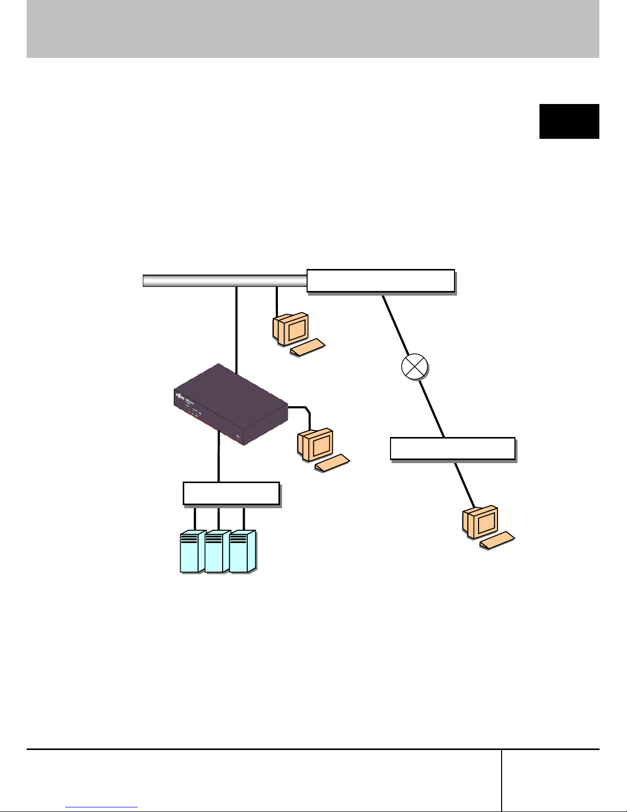
1.2. Product Outline
1
This product is a device to connect the keyboard, mouse and video port of target
device (hereinafter called Host server) to the remote terminal unit in the remote
location via network.
Setup
It is also able to switch and operate the multiple host servers from the remote location
by connecting to the KVM switch.
Router, Fire Wall, VPN
Host Server
Cat5
RJ45
IP
LAN (10M, 100M, 1000M Ethernet)
Cat5
RJ45
IP
Cat5
RJ45
IP
Router, Fire Wall, VPN
Cat5
RJ45
IP
Cat5
RJ45
IP
LAN
Remote Terminal
Network
Local
Remote Terminal
...
KVM Switch
SERVIS IP-KVM
1p Converter
User's Guide
3
Page 16
1.3 Parts and Functions
1.3. Parts and Functions
1
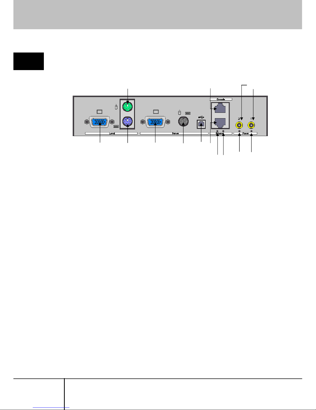
1.3.1 Rear
Setup
(7)(6)(5)(4)(1) (2)
(8)(3) (9)
(12) (13)
(10)
(11)
(1) Local Video Port
Connects the video monitor for local operation.
Connector type is female Mini D-sub15 pin.
(2) Local Keyboard Port
Connects the PS/2 keyboard for local operation.
Connector type is Mini-DIN6 pin.
(3) Local Mouse Port
Connects the PS/2 mouse for local operation.
Connector type is Mini-DIN6 pin.
(4) Server Video Port
Connects to the host server or KVM switch to be controlled with the optional
composite cable for server connection.
Connector type is female Mini D-sub15 pin.
(5) Server PS/2 Port
Connects to the host server or KVM switch to be controlled with the optional
composite cable for server connection.
Connector type is Mini-DIN8 pin.
(6) Server USB Port
Connects to the host server to be controlled with the optional USB connection
cable.
Connector type is USB type B.
SERVIS IP-KVM
1p Converter
User’s Guide
4
Page 17

1.3 Parts and Functions
(7) Ethernet Port
Ethernet connector which is compliant with 10BASE-T/100BASE-TX.
Both UTP and STP cables are available.
Connector type is RJ45 modular jack.
Refer to
4.2 RJ45 Connector Signal Assign (page 141)
1
Setup
(8) Console Port
For RS232 Connection.
Connects to this product using this Console port and set the network at initial
installation.
Connector type is RJ45 modular jack.
Refer to
1.5.4 Serial Console Connection (page 12)
(9) Power Adapter Connector
Connects the power adapter (DC5V input).
This product can connect up to 2 power adapters, redundant configuration is
supported.
(10) Ethernet Act LED
Blinks green when a data packet is sent or received by VNC connection.
(11) Ethernet Link LED
Lights up green when the Ethernet port is linked up.
(12) Power LED 2
Lights up green when the adapter is connected to power connecter 2 and power
is supplied.
(13) Power LED 1
Lights up green when the adapter is connected to power connector 1 and power
is supplied.
SERVIS IP-KVM
1p Converter
User's Guide
5
Page 18

1.3 Parts and Functions
1.3.2 Front
1
Setup
(1) Power LED
1: Lights up green when the adapter is connected to power connector 1 and
power is supplied.
2: Lights up green when the adapter is connected to power connecter 2 and
power is supplied.
(2) Ethernet LED
Link: Lights up green when the Ethernet port is linked up.
Act: Blinks green when a data packet is sent or received by VNC connection.
(3) USB LED
Lights up green when this product and the host server is connected by USB.
Blinks green if there is keyboard or mouse input when USB keyboard/mouse
are enabled.
(4) RESET Button
Resets the CPU when this product is active.
This product will be restarted in approx. 15 seconds.
SERVIS IP-KVM
1p Converter
User’s Guide
6
Page 19
1.4 Installation Method
1.4. Installation Method
1
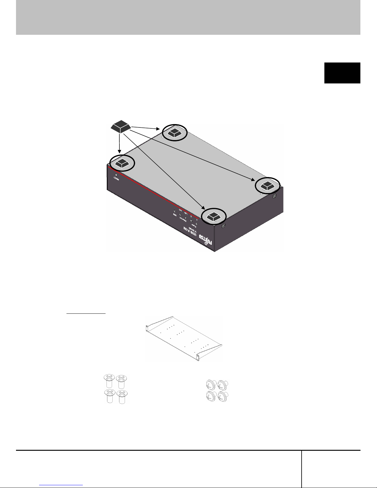
1.4.1 Placing On a Level Surface
Setup
When placing this product on a level surface such as desk, attach the provided
rubber feet to the bottom of the device. The feet cushion shock and protect slipping.
1.4.2 Rack Mount
By using optional rack mount kit, you can mount the device on a EIA standard 19
inch rack.
Refer to
4.4 Optional Accessories (page 141)
Rack Mount Kit
Rack Mount Tray
Unit/tray Screw ...4 Tray/rack support Screws... 4
SERVIS IP-KVM
1p Converter
User's Guide
7
Page 20
1.4 Installation Method
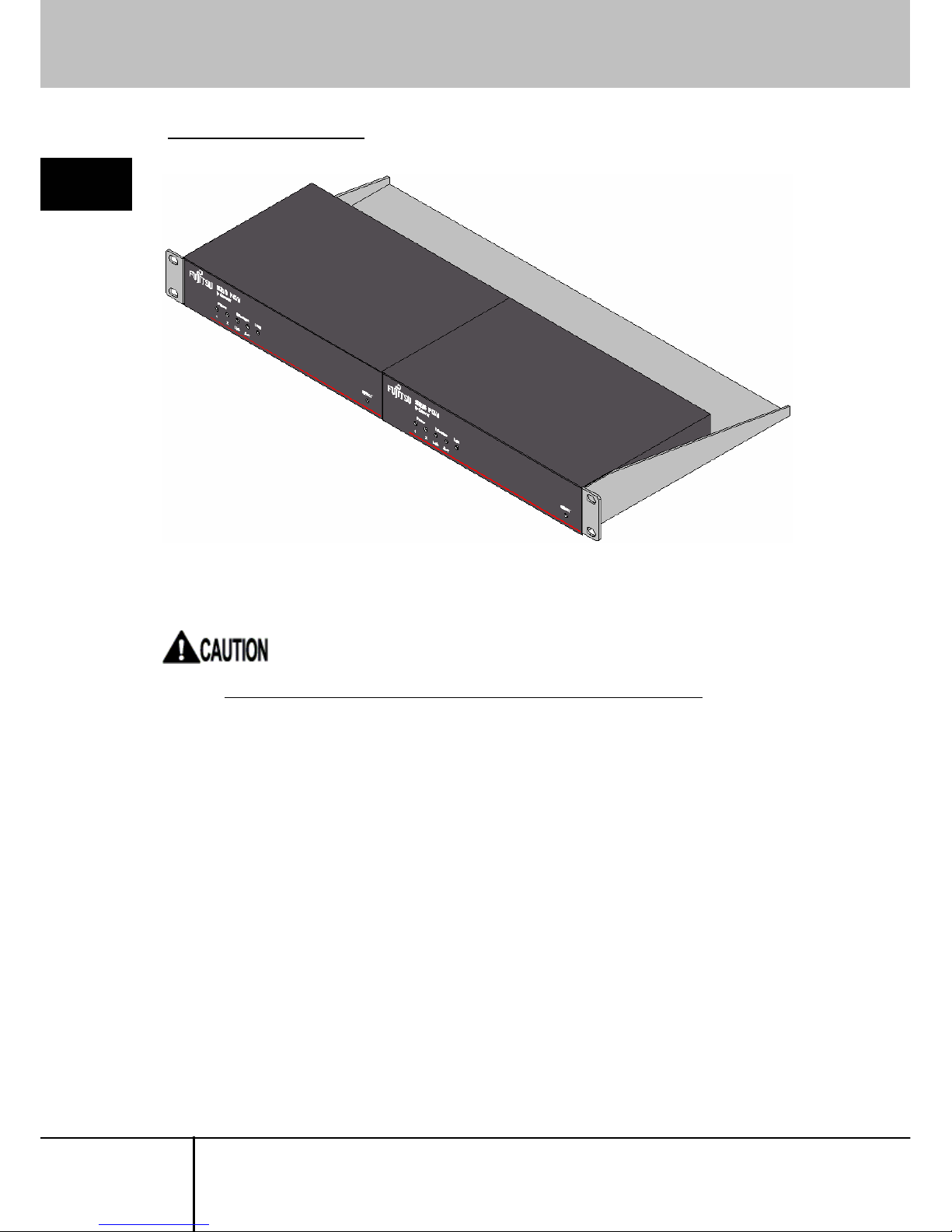
Example of rack mount setting
1
Setup
Up to 2 devices can be mounted in an EIA standard 1U rack.
When mounting the product on a 19 inch rack, remove the rubber feet.
SERVIS IP-KVM
1p Converter
User’s Guide
8
Page 21

1.5 Connecting Method
1.5. Connecting Method
1
1.5.1 Not Provided Necessary Components
(1) Composite cable for Server Connection (option)
Composite cable connects this product to the server or KVM switch.
Setup
(2) USB Connection Cable (option)
USB cable connects this product to the server.
(3) Video Monitor, Keyboard and Mouse for local operation.
Prepare a video monitor, keyboard and mouse for local operation.
PS/2 connection is only supported for a keyboard and mouse.
(4) Serial console terminal
Prepare a PC with RS-232C interface (D-Sub 9-pin or D-sub 25-pin). This is
necessary in order to set the IP address for this product at initial installation.
(5) Cat5 Cable
Prepare a Cat5 straight cable, adapted for the environment, for network
connection. Any UTP or STP is acceptable; however the cable must be
shorter than 20m.
(6) Switching Hubs, etc.
Prepare the routers and switching hubs for network connection.
(7) Remote Terminal Unit
Prepare a PC that supports an Ethernet connection.
A terminal device to operate the host server from a remote location.
An environment that Java applet runs on is needed. Any OS and browser are
acceptable.
SERVIS IP-KVM
1p Converter
User's Guide
9
Page 22
1.5 Connecting Method
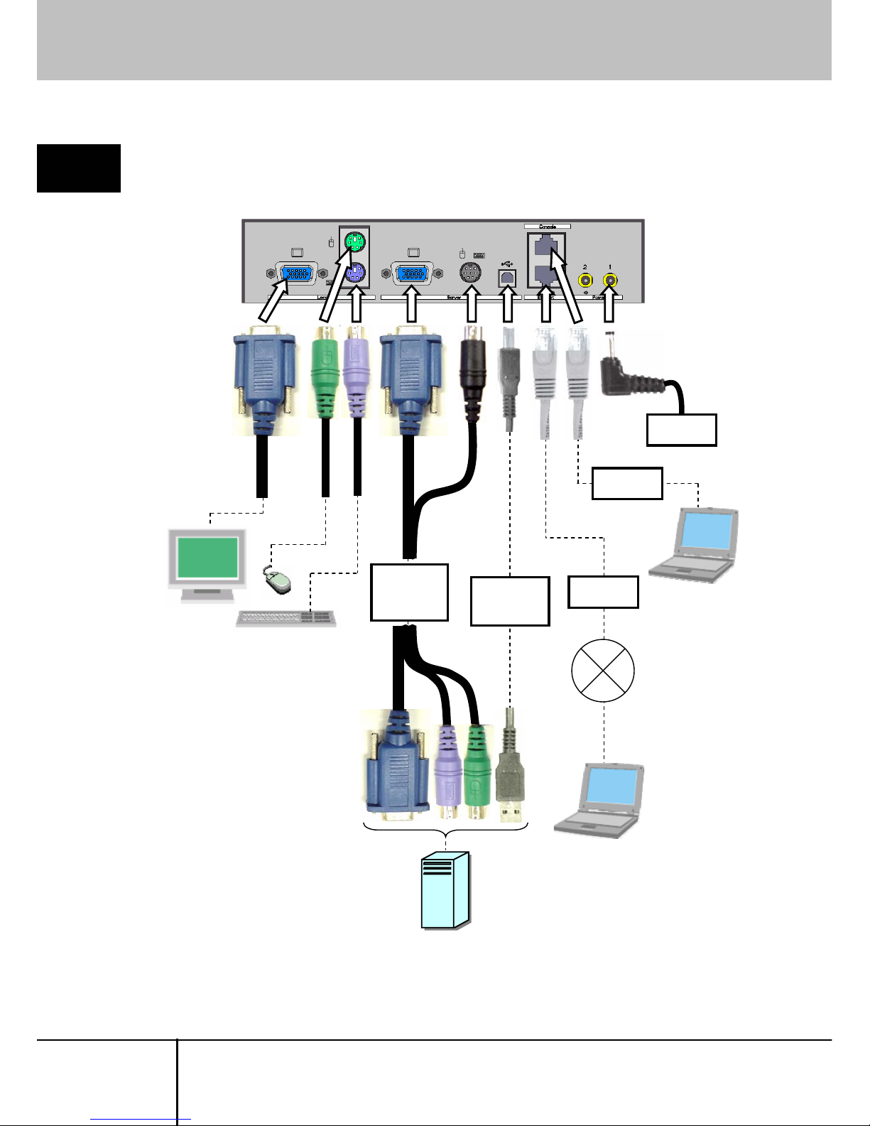
1.5.2 Connection to the Host Server
1
Connect cables to this product, as shown below.
Setup
Composite
Cable for
Server
Connection
Power
Adapter
Remote
Terminal Unit
Network
V
ideo Monitor, Keyboard
and Mouse for local operation.
Serial
Console
USB
Connection
Cable
Cat5
Cable
Cat5
Cable
Host Server
SERVIS IP-KVM
1p Converter
User’s Guide
10
Page 23
1.5 Connecting Method
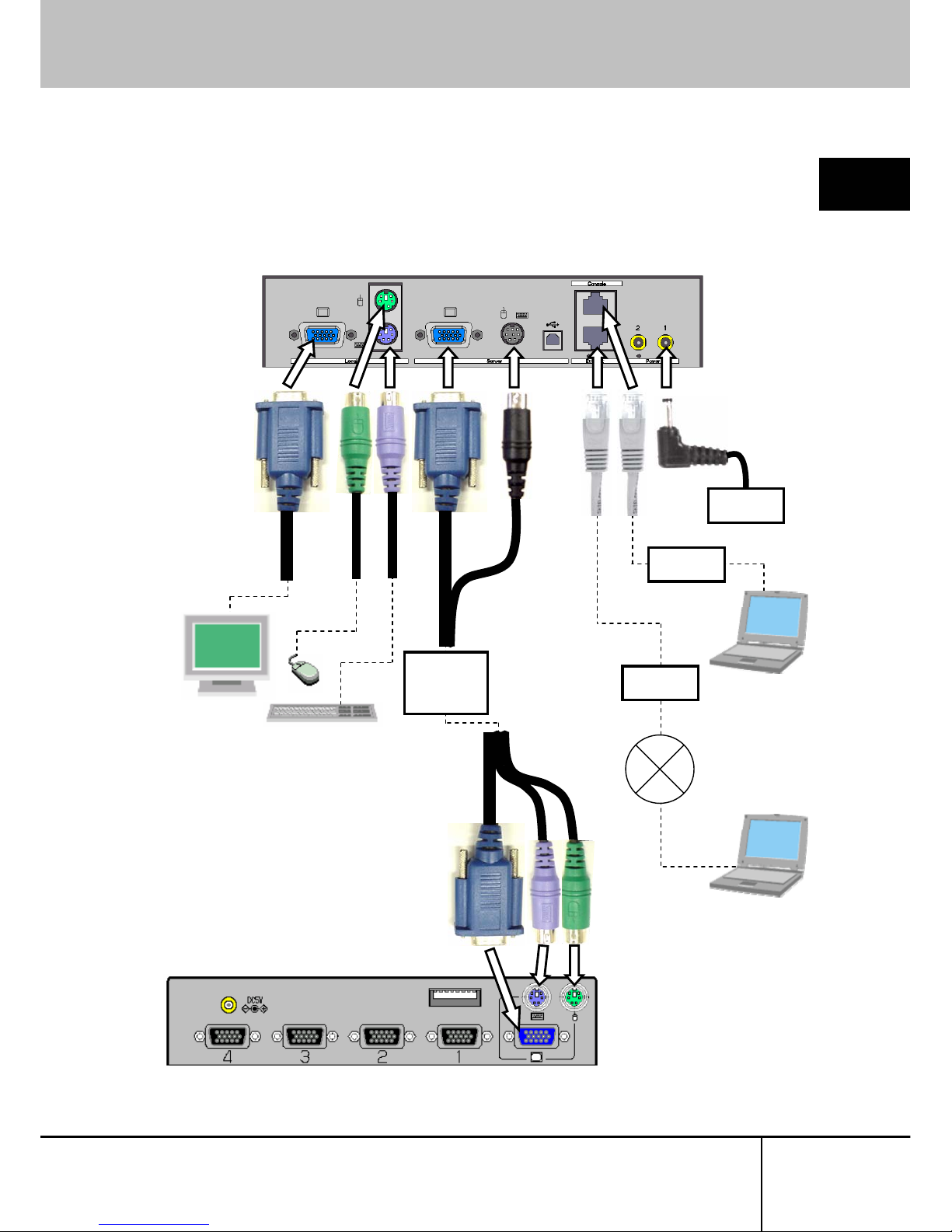
1.5.3 KVM Switch Connection
1
When you combine our KVM switch and this product, connect the cables as shown
below. Connect the KVM cable to the local port in the KVM switch
side.
Setup
Remote Terminal
Network
V
ideo Monitor, Keyboard and
Mouse for local operation.
Serial
Console
Composite
Cable for
Server
Connection
Power
Adapter
Cat5
Cable
Cat5
Cable
(Example) Rear of the KVM Switch
SERVIS IP-KVM
1p Converter
User's Guide
11
Page 24
1.5 Connecting Method
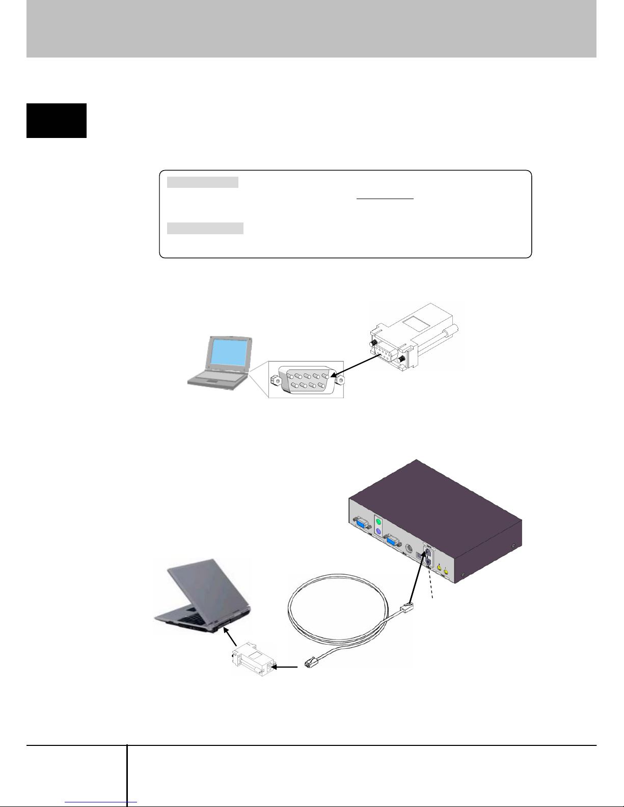
1.5.4 Serial Console Connection
1
If the COM port of serial console has a D-sub 9-pin or D-sub 25-pin connector, the
serial console can also be connected to this product with the optional D-sub−RJ45
conversion adapter and commercially available Cat5 straight cable.
Setup
FP-AD009RJX The conversion adapt er to configure RS-232C cross
cable by combining
Console port and Cat5 straight cable.
D-Sub side is female 9-pin.
FP-AD025RJX The conversion adapter same as FP-AD009RJX,
but its D-Sub side is male 25-pin.
1. Connect the FP-AD009RJX conversion adapter (for D-sub9) to the serial
console.
Serial Console Terminal
Conversion Adapter
FP-AD009RJX
COM Port (D-sub9)
2. Connect the conversion Adapter hooked up in Step1 and Console port of this
product by a Cat5 cable.
Cat5 Straight Cable
Console Port
Serial Console Terminal
SERVIS IP-KVM
1p Converter
User’s Guide
12
Page 25

1.5 Connecting Method
SERVIS IP-KVM
1p Converter
User's Guide
13
2
Basic Operation
Chapter 2 - Basic Operation
This chapter provides basic operating procedure to control the host server from a
remote location via network with this product.
Contents
2.1 Basic Operation Flow page 14
2.2 Set the IP Address (For Initial Installation)
page
15
2.3 Logon to this Product page 20
2.4 Run the Java VNC page 25
2.5 Host Server Operation from Java VNC page 29
2.5.1 Host Server Initial Setting page 30
2.5.2 VNC Menu page 32
2.5.3 Menu Window page 34
2.5.4 System ID Window page 37
2.5.5 Virtual Key Window page 38
2.5.6 Video Tune Window page 41
2.5.7 Disk Operation Window page 45
2.5.8 Take Control Window page 46
2.5.9 USB Setting Window page 47
2.5.10 KVM Menu Window page 49
2.6 Exit and Log off the Java VNC page 51
2.7 Local Operation page 53
Page 26
2.1 Basic Operation Flow
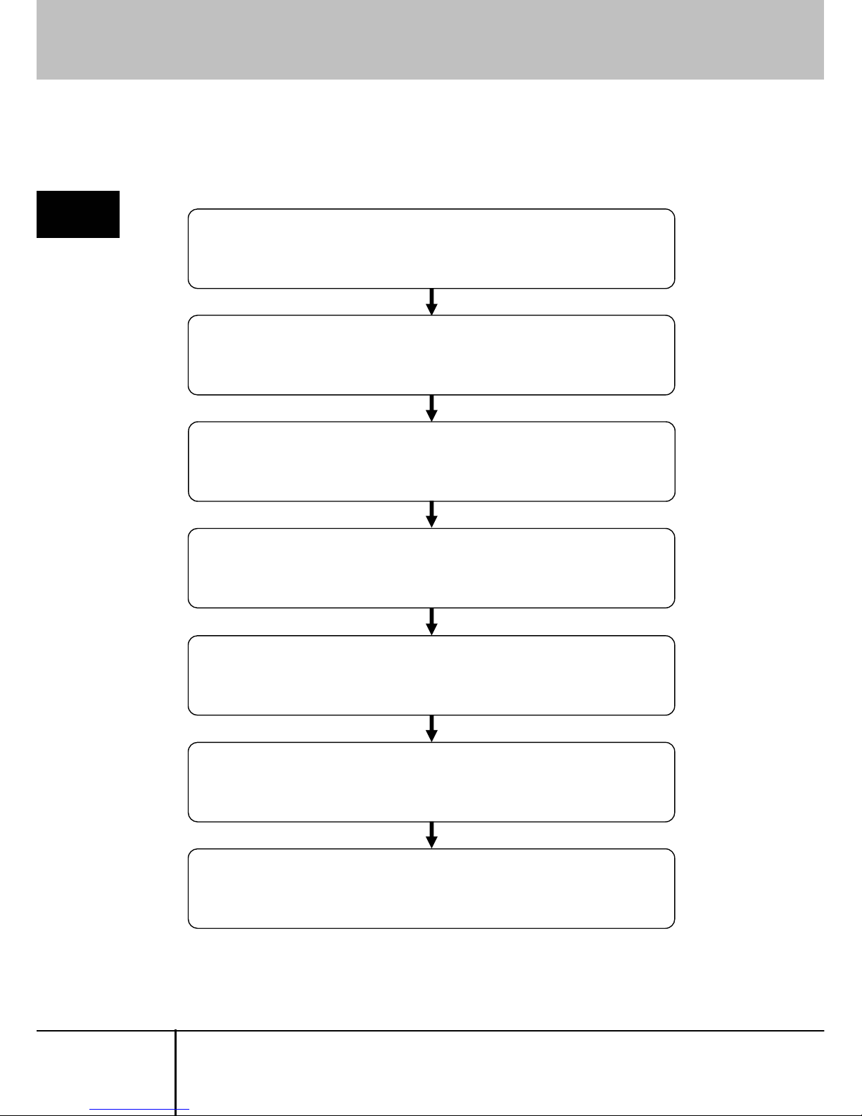
2.1. Basic Operation Flow
The following provides the basic operating procedure to control the host server from
a local or remote location via network with this product.
2
Basic Operation
Step 1 Connect this product to the host server
Connect this product to the host server and prepare for remote operation.
Refer to 1.5.2 Connection to the Host Server (page 10)
Step 2 Set the IP address for this product.
Connect the serial console to this product and set the IP address.
Refer to 2.2 Set the IP Address (For Initial Installation) (page15)
Step 3 Access to this product from remote terminal.
Access to this product and enter the [User Account]
and [Pass Word] and log on.
Refer to 2.3 Logon to this Product (page 20)
Step 4 Run the Java VNC.
Run the Java VNC and prepare for host server operation.
Refer to 2.4 Run the Java VNC (page 25)
Step 5 Operate the host server.
Operate the host server from the Java VNC operating screen.
Refer to
2.5 Host Server Operation from Java VNC (page 29)
Step 6 Exit the VNC and log out.
Exit the VNC and log out.
Refer to
2.6 Exit and Log off the Java VNC (page 51)
Step 7 Operate the host server locally.
Connect the video monitor, keyboard and mouse, and operate the host server.
Refer to 2.7 Local Operation (page 53)
SERVIS IP-KVM
1p Converter
User’s Guide
14
Page 27
2.2 Set the IP Address (For Initial Installation)
2.2. Set the IP Address (For Initial Installation)
Set the IP address for this product using serial console at initial setting. The
operation method is described below.
2
Basic Operation
1. Connect the console port of this product and the serial console terminal.
Refer to
1.5.4 Serial Console Connection (page 12)
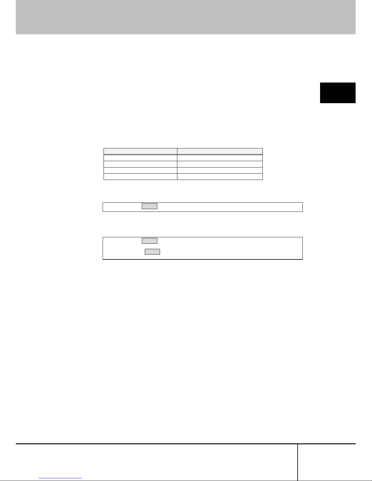
2. Run the emulator application (Tera Term, etc.) at the serial console and specify
the parameter as follows.
Condition for Communication Value
Baud Rate 115200bps
Data Length 8bit
Parity none
Stop Bit 1bit
3. The “login:” prompt is displayed. Enter the default administrator account: admin.
4. The “password:” prompt is displayed. Enter the default admin password: admin
(The password is not displayed)
login: admin Enter↵
login: admin Enter↵
password: Enter↵
SERVIS IP-KVM
1p Converter
User's Guide
15
Page 28

2.2 Set the IP Address (For Initial Installation)
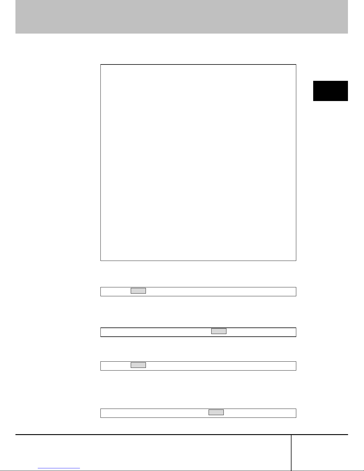
5. The following set up menu is displayed.
--------------------------SERVIS IP-KVM Network Setup
---------------------------
NOTE: This interface is used to set network parameters and perform
certain recovery procedures, but the majority of setup and
configuration can only be done using the web interface.
Primary Ethernet Port (LAN) (00:0e:00:ee:04:03)
DHCP is enabled. Current lease information:
IP Address: 192.168.0.2
Netmask: 255.255.255.0
Gateway: Disabled
Broadcast: 192.168.0.255
Machine name: noname
Default Gateway: <none> (DHCP: 192.168.0.1)
Commands (press one key, then Enter):
D - Disable DHCP, and use fixed IP address.
* I - Set IP address.
* N - Set netmask.
* G - Set network gateway.
* B - Set broadcast address (optional).
M - Change machine name (DHCP client name).
H - Reset/disable firewall, TCP ports, SNMP, RADIUS.
F - Reset everything to factory defaults.
S - Change system admin password.
P - Send ICMP ping packets (testing purposes).
? - Show TCP/IP ports and servers enabled.
V - Show Firmware Information.
R - Revert to current settings (undo changes).
W - Commit changes to configuration.
Q - Logout.
* -> These values ignored due to DHCP.
Choice:
2
Basic Operation
DHCP is enabled as the factory setting. Log on this product and
be sure to specify
the fixed IP address if you operate the host server from a remote location
extended periods of time.
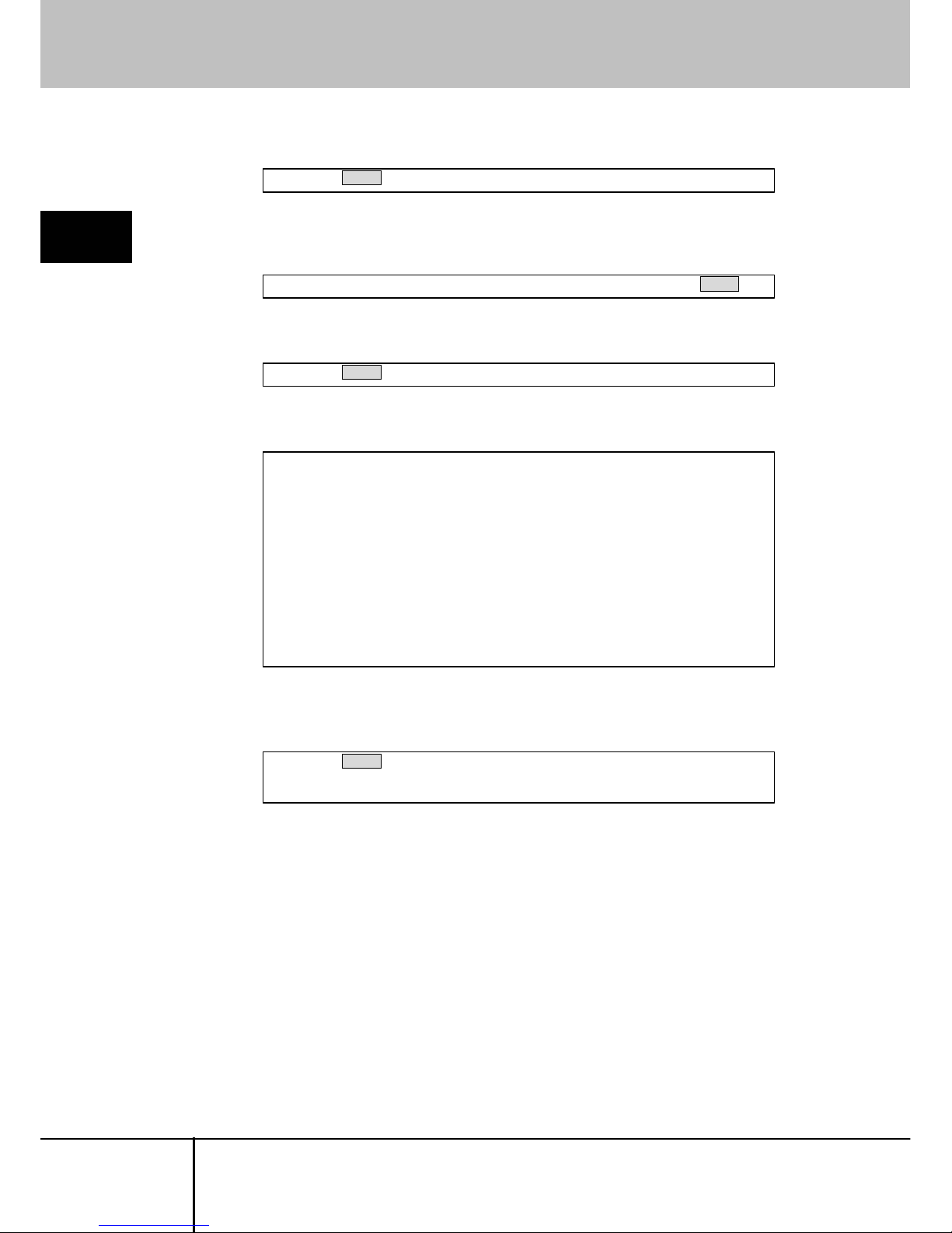
6. To assign an IP address, disable the DHCP. The “Choice:” prompt is displayed
and enter “d”.
7. The following is displayed and DHCP is disabled. Press the [Enter] key.
Choice: d Enter↵
DHCP has been disabled.
Press Enter to continue... Enter↵
SERVIS IP-KVM
1p Converter
User’s Guide
16
Page 29
2.2 Set the IP Address (For Initial Installation)
8. The following is displayed. Confirmed that the DHCP is disabled.
2
Basic Operation
9. Specify the IP address. Enter "i" in the “Choice:” prompt.
10. Current IP address is displayed in square bracket. Enter the new IP address
and press the [Enter] key.
11. Specify the subnet mask. Enter "n" in the “Choice:” prompt.
12. Current subnet mask is displayed in square bracket. Enter the new subnet
mask and press the [Enter] key. Press the [Enter] key if the subnet mask is not
changed.
Choice: i Enter↵
IP Address [192.168.0.8]: 192.168.0.100 Enter↵
--------------------------SERVIS IP-KVM Network Setup
---------------------------
NOTE: This interface is used to set network parameters and perform
certain recovery procedures, but the majority of setup and
configuration can only be done using the web interface.
Primary Ethernet Port (LAN) (00:0e:00:ee:04:03)
D.H.C.P.: Disabled
IP Address: 192.168.0.2
Netmask: 255.255.255.0
Gateway: Disabled
Broadcast: 192.168.0.255
Machine name: noname
Default Gateway: <none>
Commands (press one key, then Enter):
D - Enable DHCP for dynamic IP address.
I - Set IP address.
N - Set netmask.
G - Set network gateway.
B - Set broadcast address (optional).
M - Change machine name (DHCP client name).
H - Reset/disable firewall, TCP ports, SNMP, RADIUS.
F - Reset everything to factory defaults.
S - Change system admin password.
P - Send ICMP ping packets (testing purposes).
? - Show TCP/IP ports and servers enabled.
V - Show Firmware Information.
R - Revert to current settings (undo changes).
>>> W - Commit changes to configuration.
Q - Logout.
NOTE: Your changes are still pending.
Choice:
Choice: n Enter↵
Netmask [255.255.255.0]: 255.255.255.0 Enter↵
SERVIS IP-KVM
1p Converter
User's Guide
17
Page 30
2.2 Set the IP Address (For Initial Installation)
13. Specify the default gateway. Enter "g" in the “Choice:” prompt.
2
Basic Operation
14. Current default gateway is displayed in square bracket. Enter the new IP
address of default gateway and press the [Enter] key.
15. The “Choice:” prompt is displayed again. Enter "w" to save the new setting.
16. The following is displayed and the setting is changed.
17. Press the [Enter] key again after the setting and display the “Choice:” prompt.
Enter "q" to log off. The “login:” prompt is displayed after the log off.
Choice: w Enter↵
Writing... Done.
Applying settings...
eth0: IBM EMAC: link up, 100 Mbps Full Duplex, auto-negotiation complete.
eth0: IBM EMAC: MAC 00:0e:00:ee:04:03.
eth0: IBM EMAC: open completed
SNMP agent started.
Redir Server started (br0/eth0=80, eth1=0).
rhub: No such file or directory
VNC Server: Version V1L20ES
Done.
Changes commited.
Press Enter to continue...
Choice: g Enter↵
Default gateway (or 0.0.0.0 for none) [0.0.0.0]: 192.168.0.1 Enter↵
Choice: q Enter↵
login:
Then the network setting is changed as following value.
IP address: 192.168.0.100
Subnet mask: 255.255.255.0
Default gateway: 192.168.0.1
This is the operation method to change network initial settings.
SERVIS IP-KVM
1p Converter
User’s Guide
18
Page 31

2.2 Set the IP Address (For Initial Installation)
The following table shows the items can be specified from the serial console.
Command Items
D Switches enable/disable the DHCP setting.
I Set the IP address.
2
Basic Operation
N Set the subnet mask.
G Set the default gateway.
B Set the broadcast address.
M Set the device name.
H Reset/disable the Firewall and TCP port settings.
F Reset to the factory default.
S Set the system administrator password.
P Transmit the ICMP ping packet.
? Display the TCP/IP port and the server.
V Display the firmware inf ormation.
R Reset to the former settings.
W Save the current settings.
Q Logs off the menu.
Set the IP address of this product, net mask and default gateway at initial
installation.
SERVIS IP-KVM
1p Converter
User's Guide
19
Page 32

2.3 Logon to this Product
2.3. Logon to this Product
The following describes how to log on to this product from a remote terminal.
2
Basic Operation
1. Start up the browser at the remote terminal and access to the specified IP
address of this product by https protocols. (The following provides the
procedure for Microsoft Internet Explorer 6.0.)
This product is set as follows.
¾ IP Address: 192.168.0.100
¾ Subnet mask: 255.255.255.0
¾ Default Gateway: 192.168.0.1
https://192.168.0.100/
2. The [Security Alert] dialogue box is displayed. Click [Yes] button.
SERVIS IP-KVM
1p Converter
User’s Guide
20
Page 33

2.3 Logon to this Product
3. If JavaScript is disabled in the browser setting, the following [Language Select]
page is displayed. If JavaScript is disabled, this product does not operate
properly.Please enable your JavaScript and click English or Japanese.
If JavaScript is enabled, the [Language Select] page is not displayed.Refer to
the next section 4.
2
Basic Operation
SERVIS IP-KVM
1p Converter
User's Guide
21
Page 34

2.3 Logon to this Product
Setting procedure of enabled JavaScript.
For Internet Explorer 6.0
Click [Tools] menu → [Internet Options] → [Security] tab and the
following dialogue box is displayed. Click "Custom level" button.
The following [Security settings] setting is displayed.
Check the under Scripting category enable Active Scripting, and click
[OK] button.
The following [Warning] dialogue box is displayed. Cli ck [Yes] button.
Then JavaScript is enabled.
2
Basic Operation
SERVIS IP-KVM
1p Converter
User’s Guide
22
Page 35

2.3 Logon to this Product
4. The web page login screen is displayed. Click English or Japanese on the
center of the screen to switch the language.
The administrator account [admin] and the password [admin] are set by default.
Enter [admin] for the user name and the password and click [Login] button.
2
Basic Operation
Click
Download our root public certificate and you can download the security
certificate.
If cookie is disabled, you can't login to the setting page. Please enable cookie and
click [Login] button.
Refer to
5.1.6 Cannot Login to the Setting Page (page146)
SERVIS IP-KVM
1p Converter
User's Guide
23
Page 36

2.3 Logon to this Product
5. The following screen is displayed. Click the menu from the menu selection in
the left and the selected contents are displayed in menu display area in the right.
The server information is displayed in the menu display area in the top page. It
is possible to confirm power status (on/off) and the video mode (screen
resolution and refresh-rate) of the connected host server.
All management/setting for this product, besides the IP address setting in the
initial installation can be specified in this web page. Log on with administrator
account to specify/manage this product.
2
Basic Operation
Refer to
3.1 Network Setting (page 56)
Menu-display area Menu-selecting area
SERVIS IP-KVM
1p Converter
User’s Guide
24
Page 37

2.4 Run the Java VNC
2.4. Run the Java VNC
It is necessary to run the Java VNC to operate the host server after logging on from
the remote terminal.
2
Basic Operation
Confirm whether the Sun Java applet is installed or not in the remote terminal to
run the Java VNC.
For Internet Explorer:
Click [Tools] menu → [Internet Options] → [Advanced] tab. Make sure
that Java Sun [Use JRE 1.x.x._xx for <applet> (requires restart)] is
checked. (x is version No.)
If not,
Download Java software in the following web site and install it.
http://www.java.com/ja/ (Download page for the Java software).
SERVIS IP-KVM
1p Converter
User's Guide
25
Page 38

2.4 Run the Java VNC
1. Click
VNC login (more secure) in the menu-selecting area.
2
Basic Operation
SERVIS IP-KVM
1p Converter
User’s Guide
26
Page 39

2.4 Run the Java VNC
2. [VNC login (more secure) via Java applet] screen is displayed.
If the Java applet is not installed, the screen remains the same and the Java
VNC is not run. Download the latest Java software.
(Support Java version: JRE 5.0 Update 6, J2SE v1.4.2_11 JRE)
2
Basic Operation
If the Java applet is installed, the following [Warning - Security] dialogue box is
displayed. Click [Yes] button. (Dialogue window depends on Java version)
SERVIS IP-KVM
1p Converter
User's Guide
27
Page 40

2.4 Run the Java VNC
3. Once the VNC window opens and the host server screen is displayed,
operation is possible.
2
Basic Operation
Refer to the next section for details about the VNC window.
If you update the Java applet, uninstall the old version, and then install the
latest version.
If you don't uninstall the old version of the Java applet and you install the latest
version, this product may not operate normally.
SERVIS IP-KVM
1p Converter
User’s Guide
28
Page 41

2.5 Host Server Operation from Java VNC
2.5. Host Server Operation from Java VNC
Starting up VNC, the following window is displayed and the host server operation is
enabled.
2
Basic Operation
The
black square cursor is for the remote terminal side and white arrow is for the
host server side. The host server cursor follows the remote terminal cursor's
movement.
Host server Screen Area
Remote Terminal's
Mouse Cursor
Menu bar-display area
Host Server's
Mouse Cursor
To synchronize the remote terminal and host server cursor position, disable the
acceleration setting for the host server mouse.
Refer to
2.5.1 Host Server Initial Setting (page 30)
SERVIS IP-KVM
1p Converter
User's Guide
29
Page 42

2.5 Host Server Operation from Java VNC
2.5.1 Host Server Initial Setting
To synchronize the remote terminal and host server cursor position, disable the
[Acceleration] setting and the [Move to Default Button] setting.
2
Basic Operation
¾ For Windows OS based host servers
Click [Control Panel] - [Mouse] and display the mouse properties.
For Windows 2000
→ Speed: Middle, Aceleration: None
→ Snap to default: Clear the check box
For Windows XP and Windows Server 2003
→ Motion: Middle,
Enhance Pointer precision: Clear the check box
→ Snap To: Clear the check box
Clear the check box
Clear the check box
SERVIS IP-KVM
1p Converter
User’s Guide
30
Page 43

2.5 Host Server Operation from Java VNC
¾ For RedHat Linux (GNOME) Based Host Server.
Click [Preferences] - [Mouse] and display the mouse preferences.
→
Aceleration: Middle (For slowish side)
2
Basic Operation
When PS/2 keyboard/mouse is enabled and the host server is a Windows OS,
The
mouse cursor is not synchronized before login to the server.
SERVIS IP-KVM
1p Converter
User's Guide
31
Page 44

2.5 Host Server Operation from Java VNC
2.5.2 VNC Menu
The following menu bar is displayed at the top of the VNC window.
Menu bar buttons provide various functions.
2
Basic Operation
VNC Menu Bar
Shows the LED status from the left Num Lock, Caps Lock and Scroll
Lock. If the LED off, it is displayed in gray.
Shows current transmission capacity (baud rate) / delay time.
Display the menu window.
Refer to
2.5.3 Menu Window (page 34)
Correct the difference between host server side and remote terminal
side mouse pointers position. If the USB absolute mouse enabled,
the button cannot be selected.
Refer to
3.3.3.4 Disable USB Absolute Mouse Support (page 88)
Input [Crtl] - [Alt] - [Delete] key to the host server.
Ctl-Alt-Del button is displayed if you select "Generic or US/English"
or “Japanese (106/109 keys)” in [Keyboard Mapping (for
or
localization)].
Strg-Alt-Entf button is displayed if you select “German (QWERTZ
layout)” in [Keyboard Mapping (for localization)].
Refer to 3.3.3.2 Keyboard Mapping (for localization) (page86)
Display the virtual key window.
Refer to
2.5.5 Virtual Key Window (page 38)
Reset the PS/2 emulation. Use this button in case the mouse pointer
or PS/2 keyboard is disabled. If the USB keyboard/mouse enabled,
the button cannot be selected.
Display the USB menu window. If the device is not connecting to the
host server by USB cable, the button cannot be selected.
Refer to 2.5.9 USB Setting Window (page 47)
If using with a KVM switch, output the specified hot keys to the KVM
switch. It is not displayed in default. The button is displayed if you
select other than "Disable" in [Hot Key configuration of FCL KVM
Switch].
( Refer to
REF _Ref118884558 ¥r ¥h ¥* MERGEFORMAT
3.3.3.1 REF _Ref118884562 ¥h ¥* MERGEFORMAT
Hot Key configuration of FCL KVM Switch (page 85)
If using with a KVM switch, reset the KVM switch. It is not displayed
in default. The button is displayed if you select other than "Disable" in
[Hot Key for FCL KVM Switch setting].
Refer to
3.3.3.1 Hot Key configuration of FCL KVM Switch (page
85)
Update the host server display area.
Indicates the mouse pointer's automatic correction function. Click
this indication to enable/disable the function. If the function disabled,
the indicator is displayed in gray.
SERVIS IP-KVM
1p Converter
User’s Guide
32
Page 45

2.5 Host Server Operation from Java VNC
If you use this product with a KVM switch, click [KVM] button. The following OSD
screen is displayed.
(The following diagram shows the combination with SERVIS Multi and
FS-1004MT).
2
Basic Operation
Select the number by cursor ↑ or ↓ and press the Enter key. Host servers
connected to the selected port are displayed and operation is enabled.
SERVIS IP-KVM
1p Converter
User's Guide
33
Page 46

2.5 Host Server Operation from Java VNC
2.5.3 Menu Window
Press the F7 key twice or click [Menu] button in VNC menu bar, following menu
window is displayed.
This menu window provides various VNS connection settings.
2
Basic Operation
The following table shows the details about the menu window.
SERVIS IP-KVM
1p Converter
User’s Guide
34
Page 47

2.5 Host Server Operation from Java VNC
Operation Selecting Area (Left of the menu window)
System ID Displays the specified system information.
Refer to
3.4.1 Identification (page 114)
Mouse Resyn Synchronises the remote terminal and host server cursor position. If
the USB absolute mouse is enabled, the button is displayed in gray.
Refer to 3.3.3.4 Disable USB Absolute Mouse Support (page 88)
2
Basic Operation
PS/2 Reset Reset the PS/2 emulation. Use this button in case the mouse pointer
or PS/2 keyboard is disabled.
USB Menu Display the USB menu window. If the device is not connected to the
host server by USB cable, the button is displayed in gray.
Refer to 2.5.9 USB Setting Window (page 47)
Video Reset Update the host server display area.
Take Ctrl When multiple users connect to the same system and the other user
establishes the control authority, takes control authority from the user.
Only one user can operate by keyboard and mouse.
Refer to
3.8 Concurrent Connection of Network Users (page 136)
Video Tune Displays the Video Tune window for fixing the video image.
It is used when video tuning is performed manually.
Refer to 2.5.6 Video Tune Window (page 41)
VirtKeys Displays the virtual keyboard that provides special key
(Control-Alt-Delete, etc.) for the host server.
Refer to 2.5.5 Virtual Key Window (page 38)
Disk Ctrl Displays the disk operation window to emulate the USB virtual disks.
Refer to
2.5.7 Disk Operation Window (page 45)
Menu Bar Switches display/hide the menu bar at the top of the VNC window.
KVM Menu Displays the KVM menu window.
Refer to
2.5.10 KVM Menu Window (page 49)
Close Closes the menu window
Setting Display Area (Right of the menu window)
Host power: If the host server is on: On is displayed,
if the host server is off: Off is displayed.
Video mode: Displays the graphic mode setting for host server. (Example: 800 x
600 @ 60Hz)
If the host server is off: No power is displayed.
KB mouse I/F: Displays the host server keyboard and mouse are connecte d whether
PS/2 or USB.
LED State: Displays keyboard LED is on/off. (If the LED is off, the menu is
displayed in gray).
Indicates each LED status, [Num] for NumLock, [Caps] for CapsLock,
and [Scroll] for ScrollLock.
Power In: Displays the connecting status of the product's power port 1 and 2.
If the power port is connected, "plugged" is displayed and "unplugged"
for unconnected status.
Displays the IP address. My IP:
Displays the specified current date and time. Time:
Displays current network transmission rate and delay time. Tx rate/delay:
Specify the bandwidth control. S pecify Fast: for less than 12Mbp s, A vg
for less than 4Mbps, and Min for less than 700kbps.
B/W:
Select "Auto" for this setting, appropriate setting is automatically
selected.
Thumbnails: Resizes the screen image from half size down to one sixteenth by
clicking [1/2]. [1/4], [1/8] and [1/16]. Restore the image to the original
size by clicking the screen.
SERVIS IP-KVM
1p Converter
User's Guide
35
Page 48

2.5 Host Server Operation from Java VNC
If multiple products are set up on the same network, each VNC screens is displayed
as small thumbnail images. (Select the size from [1/2], [1/4], [1/8] or [1/16] in the
menu window).
This function allows control of multiple host servers.
2
Basic Operation
Restore the image by clicking the thumbnail screen.
SERVIS IP-KVM
1p Converter
User’s Guide
36
Page 49

2.5 Host Server Operation from Java VNC
2.5.4 System ID Window
Click [System ID] in the menu window and the following system ID window is
displayed.
2
Basic Operation
Display the system ID of this product specified in
Identification in the
web site.
Refer to
3.4.1 Identification (page 114)
System ID Window
Hostname: Display the ID of this product.
Net Addr: Display the user-defined value; the DNS name for console,
etc.
Description: Display the user-defined construction for controlled dev ices.
Location: Display installation site of this product.
Contact: Display the contact information; mail addresses relating to this
product, etc.
SERVIS IP-KVM
1p Converter
User's Guide
37
Page 50

2.5 Host Server Operation from Java VNC
2.5.5 Virtual Key Window
Click [VirtKeys] from the VNC menu bar or click [VirtKeys] in the menu window,
virtual key window is displayed.
This window provides specific keys, which cannot be directly input into the host
server from the remote terminal unit (Ctrl + Alt + Del for example).
2
Basic Operation
The layout of the virtual key window changes by "Keyboard Mapping" setup of the
Web page.
Refer to
3.3.3.2 Keyboard Mapping (for localization) (page86)
z The case of ”Generic or US/English” or “Japanese (106/109 keys)”
z The case of ”German (QWERTZ layout)”
SERVIS IP-KVM
1p Converter
User’s Guide
38
Page 51

2.5 Host Server Operation from Java VNC
z Virtual Key Input Method
By clicking the virtual keys, the items in the square frame are input to the host
server.
z Usage of the Toggle Keys
The keys of the dark gray surrounded in the red in the virtual key window shown
below show the toggle keys. By clicking the toggle key in the virtual key window,
the key becomes a toggle key in the host server.
The diagram below shows the [L-Ctrl] button clicked in the virtual key window and
the key in toggle status.
2
Basic Operation
Switch focus from the virtual key window and enter "a" from the keyboard in this
status, will transmit the "L-Ctrl + a" command to the host server.
Click [L-Ctrl] button in the virtual key window again, the toggled status is
deactivated and the button becomes normal.
Switch focus from the virtual key window to enter commands to the host
server from the keyboard.
SERVIS IP-KVM
1p Converter
User's Guide
39
Page 52

2.5 Host Server Operation from Java VNC
z Virtual Keys for Sun PC
The key surrounded in the blue in the virtual key window shown below is a key
corresponding to a Sun keyboard.
2
Basic Operation
Key Contents
Mute Input [Mute] key to the host server.
Vol- Input [Vol-] key to the host server.
Vol+ Input [Vol+] key to the host server.
Sleep Input [Sleep] key to the host server.
Help Input [Help] key to the host server. (Toggle Key)
Cmps Input [Compose] key to the host server. (Toggle Key)
Stop Input [Stop] key to the host server. (Toggle Key)
Again Input [Again] key to the host server. (Toggle Key)
Prop Input [Props] key to the host server. (Toggle Key)
Undo Input [Undo] key to the host server. (Toggle Key)
Frnt Input [Front] key to the host server. (Toggle Key)
Copy Input [Copy] key to the host server. (Toggle Key)
Open Input [Open] key to the host server. (Toggle Key)
Pste Input [Paste] key to the host server. (Toggle Key)
Find Input [Find] key to the host server. (Toggle Key)
Cut Input [Cut] key to the host server. (Toggle Key)
These keys are displayed in gray if you connect by PS/2 and select "Disable" in
[Hot Key configuration of FCL KVM Switch].
Refer to
3.3.3.1 Hot Key configuration of FCL KVM Switch (page85)
Click [X] button to close the virtual key window.
Even if the Ctrl + Alt+ Del key is entered from the remote PC, the command is not
transmitted to the host server.
Click [Crtl + Alt + Del] key from virtual key window to command the host server.
SERVIS IP-KVM
1p Converter
User’s Guide
40
Page 53

2.5 Host Server Operation from Java VNC
2.5.6 Video Tune Window
Click [Video Tune] in the menu window and the following Video Tune window is
displayed. Refer to the following chapter for details about Video Tunes.
Refer to
5.1.13 Increase Image Quality (page 156)
Use this window to fix the video images.
2
Basic Operation
SERVIS IP-KVM
1p Converter
User's Guide
41
Page 54

2.5 Host Server Operation from Java VNC
The following table provides description for every particular item in the window.
Moves the host server screen to the left.
2
Basic Operation
Moves the host server screen to the right.
Moves the host server screen to the top.
Moves the host server screen to the bottom.
Moves the host server screen to the default position.
Automatically corrects the display position in the host server display area.
Saves the current host server screen position,
Back to the factory default setting.
Automatically corrects the Color Offset value based on the test pattern.
Saves the current Color Offset value.
Displays the advanced settings screen for the video image and e nables
to fix the value manually.
Automatically adjusts the video signal phase.
Adjusts Picture Positioning, Color Offset & Gain, and Sampling
Phase automatically.
Enables filtering the video signal noise.
Disables the filtering function.
Raise the filtering level. Click ↑ or ↓ button to adjust the filtering level.
Decrease the filtering level.
Close the [Video Tune] screen.
SERVIS IP-KVM
1p Converter
User’s Guide
42
Page 55

2.5 Host Server Operation from Java VNC
Click [Advanced] button in the [Video Tune] window, the following setting window is
displayed.
2
Basic Operation
This window provides the manual advanced setting for image quality.
SERVIS IP-KVM
1p Converter
User's Guide
43
Page 56

2.5 Host Server Operation from Java VNC
Save up to 16 video settings.
−
If the setting is saved, the button is displayed.
If not, the button is displayed in gray.
Changes the video setting back to the factory default settings.
2
Basic Operation
Offset Manually specify the offset.
Gain Manually specify the gain.
Reset to the default setting.
Click this button and presets number button; current setting is saved to
the specified number.
The offset and gain is automatically set.
Manually specify the sampling phase.
Redisplay all the parts in the screen.
Display the updated parts.
Close the advanced settings screen for the video image.
Refer to https://IP address for this product/images/pattern.png for the test pattern
used in Color Offset tuning.
Save this test pattern in the host server as a png file.
To set the [Color Offset & Gain] in the Video Tune window,
display this test pattern in the host server screen.
SERVIS IP-KVM
1p Converter
User’s Guide
44
Page 57

2.5 Host Server Operation from Java VNC
2.5.7 Disk Operation Window
Click [Disk Ctrl] in the menu window and the following virtual disk operation window
is displayed. (It is necessary to be connected with an USB cable.)
2
Basic Operation
This window displays the USB virtual disk status and whether it is inserted or
ejected.
Disk Ctrl Window
Displays whether virtual disk is inserted or ejected.
Ejected: Host server does not recognize the virtual disk.
Inserted: Host server recognizes the virtual disk.
Displays the USB disk type (CD-ROM, 8M RAM, and Floppy).
Inserts the virtual disk. (The menu is displayed in gray while the disk is
inserted).
This makes the host server recognize the virtual disk.
Ejects the virtual disk. (The menu is displayed in gray while the disk is not
inserted).
This makes a remote user access the virtual disk.
Disconnects the USB connection and connect again.
Closes the [Disk Operation] window.
Refer to the following section for further details about the virtual disk.
Refer to
3.3.4 Virtual Disk Setting (page 91)
SERVIS IP-KVM
1p Converter
User's Guide
45
Page 58

2.5 Host Server Operation from Java VNC
2.5.8 Take Control Window
If an user is already operating the host server when another user try VNC
connection, the latter user can only monitor the screen, but cannot operate the
keyboard and mouse.
If you move the mouse cursor or press the keys on the VNC screen area, the
following dialogue box is displayed.
Click [Take control now] button and the following dialogue is displayed, and then you
can obtain the host server control authority.
You can also obtain the operating authority by clicking [Take Ctrl] from the menu
window.
2
Basic Operation
SERVIS IP-KVM
1p Converter
User’s Guide
46
Page 59

2.5 Host Server Operation from Java VNC
2.5.9 USB Setting Window
Click [USB] on the VNC menu bar to display the USB setting window.
This window sets USB keyboards, mouse and storages.
2
Basic Operation
USB Setting Window
Select one USB device setting from the following three.
The selected button is displayed.
Keyboard, Mouse,
Storage :
Click [Set] button to enable USB keyboard, USB mouse and USB
virtual disk.
Keyboard, Mouse :
Click [Set] button to enable USB keyboard and USB mouse.
(Default setting)
USB virtual disk is disabled.
Keyboard :
Click [Set] button to enable only USB keyboard.
USB mouse and virtual disk are disabled.
ABS
It shows the absolute mouse is enabled.
If the relative-value mouse is enabled, the button is displayed in
gray.
REL
It shows the relative-value mouse is enabled. (Default setting)
If the absolute-value mouse is enabled, the button is displayed in
gray.
USB Replug :
Click [do] button to simulate connect and disconnect of the USB
connector.
This button fixes error in case an access error occurred in the host
server.
Close the USB Menu window.
SERVIS IP-KVM
1p Converter
User's Guide
47
Page 60

2.5 Host Server Operation from Java VNC
If the host server is rebooted, USB virtual disk function will be ”Disable”
automatically.
2
Basic Operation
When you use USB virtual disk function again after the host server starts,
please set USB Device setup as [Keyboard, Mouse, Storage].
SERVIS IP-KVM
1p Converter
User’s Guide
48
Page 61

2.5 Host Server Operation from Java VNC
2.5.10 KVM Menu Window
Click the [KVM Menu] in the VNC menu bar and the following KVM hot key setting
window is displayed.
Input hot keys to the connected KVM switch from this window.
2
Basic Operation
SERVIS IP-KVM
1p Converter
User's Guide
49
Page 62

2.5 Host Server Operation from Java VNC
KVM Hot Key Setting Window
Click [Ctrl+Shift+Alt] button to display the server select
screen.
Click [Ctrl x 2] button to enter the server select mode.
SERVER SELECT:
2
Basic Operation
Click [Scroll Lock x 2] button to display the server select
screen.
SHOW SERVER NAME: Click [On/Off] button to switch always display / not display the
server name in the top-left of the host server screen.
Hot keys to be used depend on the connected KVM switch models.
Refer to the KVM switch instruction about hot key specifications.
Click [Log On] button to display the log on screen.
Click [LogOff (Alt+Scroll x 2)] button to log off the KVM
switch-setting screen.
MULTIUSER ACCESS:
Click [LogOff (Ctrl+Caps x 2)] button to log off the KVM
switch-setting screen.
INIT SERVER NAME: Click [Init] button to reset the server name in the top-left of the
host server screen.
Close the KVM hot key setting window.
SERVIS IP-KVM
1p Converter
User’s Guide
50
Page 63

2.6 Exit and Log off the Java VNC
2.6. Exit and Log off the Java VNC
Exit the VNC connection after finishing the operation to the host server. Then log off
of the web site.
2
Basic Operation
1. Click [x] button in top right of the Java VNC window to exit the VNC.
SERVIS IP-KVM
1p Converter
User's Guide
51
Page 64

2.6 Exit and Log off the Java VNC
2. Click
logout from the menu selection area in the web site. The session is over
and the log on screen is displayed again.
2
Basic Operation
Click
Login again to return to the log on screen again.
SERVIS IP-KVM
1p Converter
User’s Guide
52
Page 65

2.7 Local Operation
2.7. Local Operation
Connect video monitor, keyboard and mouse to the local port for local host server
operation.
2
Basic Operation
Even if the remote terminal cannot access this product because of network errors, it
is possible to connect to the local port and operate the host server.
Only PS/2-compliant keyboard and mouse can be connected.
Refer to
1.5.2 Connection to the Host Server (page 10)
The Video monitor, keyboard, and mouse should be left unconnected during normal
operation and only be connected when necessary.
Refer to the following section about information for when an online user and a local
user operate the host server concurrently.
Refer to
3.3.1.4 VNC Idle Timeout (page 80)
As restriction, local connected keyboard LEDs (NumLock, CapsLock and
ScrollLock) is not lit up. However, the self-luminous keyboard is excluded.
SERVIS IP-KVM
1p Converter
User's Guide
53
Page 66

2.7 Local Operation
SERVIS IP-KVM
1p Converter
User’s Guide
54
MEMO
2
Basic Operation
Page 67

2.7 Local Operation
SERVIS IP-KVM
1p Converter
User's Guide
55
Chapter 3 - Function Details
3
Function Details
This chapter provides the function details of the product.
Contents
3.1 Network Setting page 56
3.1.1 IP Address and DNS page 57
3.1.2 Port Numbers page 60
3.1.3 Firewall page 63
3.1.4 SNMP Configuration page 65
3.2 Security Setting page 69
3.2.1 User Management page 70
3.2.2 Idle Session Timeout page 74
3.3 VNC Operation Setting page 75
3.3.1 VNC login and Timer page 76
3.3.2 Disconnect all VNC users page 82
3.3.3 Keyboard/Mouse/KVM Setup page 84
3.3.4 Virtual Disk Setting page 91
3.4 Other Setting page 113
3.4.1 Identification page 114
3.4.2 Recent system log entries page 116
3.4.3 Set date & time page 118
3.5 Information page 120
3.5.1 Basic Information page 121
3.5.2 Identification (Information) page 126
3.5.3 Date & Time page 127
3.5.4 Keyboard/Mouse/KVM page 128
3.5.5 Firmware Information page 129
3.5.6 Copyright Notices page 130
3.6 Flash/Firmware Management page 131
3.6.1 Flash/Firmware Management page 131
3.7 Operation for General User page 135
3.8 Concurrent Connection of Network Users page 136
3.9 Operation by VNC Software page 137
Page 68

3.1 Network Setting
3.1. Network Setting
The network setting for this product is performed on web page (for initial installation,
it is specified from the serial console).
Refer to the following sections for each item of network settings.
3
Function Details
SERVIS IP-KVM
1p Converter
User’s Guide
56
Page 69

3.1 Network Setting
3.1.1 IP Address and DNS
Click
IP Address and DNS Configuration from the menu selecting area and following
setting menu is displayed.
The IP address and DNS of this product can be changed in this menu.
3
Function Details
SERVIS IP-KVM
1p Converter
User's Guide
57
Page 70

3.1 Network Setting
Select enabled/disabled from the list for setting the IP address dynamic allocation by
DHCP as shown below.
When DHCP is enabled, [Current DHCP lease information] is displayed as shown
below.
When DHCP is disabled, input the following settings to the web page.
3
Function Details
SERVIS IP-KVM
1p Converter
User’s Guide
58
Page 71

3.1 Network Setting
After inputting the setting, click [Commit] button. The following message is displayed
and the settings are saved.
Click [Make changes effective now] button. The following message is displayed and
the changed settings applied.
3
Function Details
Make sure to specify the fixed IP address when you log on this product and
operate for a long periods.
SERVIS IP-KVM
1p Converter
User's Guide
59
Page 72

3.1 Network Setting
3.1.2 Port Numbers
Click
Port Numbers from the menu-selecting area, the following setting page is
displayed.
Network port numbers can be changed on this page.
3
Function Details
SERVIS IP-KVM
1p Converter
User’s Guide
60
Page 73

3.1 Network Setting
The following table shows the network servers currently running on this product.
This function enables to disable some of these services and set any network port
number.
Service Explanation Default Network Port Number
ssh Secure Shell 22
http HyperText Transfer Protocol 80
snmp Simple Network Management Protocol
(UDP)
161
3
Function Details
https H ypertext Transfer Protocol Security (SSL
encryption)
443
vnc VNC/RFB Protocol 5900
vncs VNC (SSL encryption) 15900
Specify "0" for the port number to disable the service.
After inputting the port number, click [Commit Changes] button. The following
message is displayed and the setting is saved.
After inputting the port number, click [Restart Servers] button. The following
message is displayed and the network servers are restarted.
SERVIS IP-KVM
1p Converter
User's Guide
61
Page 74

3.1 Network Setting
Specify the efficient port number between 1 and 65535.
The network port number must be the unique number in the IP address.
Local Host: 127.0.0.1
Only the running process on this product can receive the following ports. The
following ports do not accept external access and cannot change the number.
These numbers will be required after ssh establishes the tunnel connection. Note
that all services use default port numbers.
3
Function Details
Service Explanation Default Network Port Number
http HyperText Transfer Protocol 80
snmp Simple Network Management Protocol
(UDP)
161
vnc VNC/RFB Protocol 5900
SERVIS IP-KVM
1p Converter
User’s Guide
62
Page 75

3.1 Network Setting
3.1.3 Firewall
Click
Firewall from the menu-selecting area, the following setting page is displayed.
Security items are set in this page.
3
Function Details
SERVIS IP-KVM
1p Converter
User's Guide
63
Page 76

3.1 Network Setting
The internal Firewall function is supported to protect the network.
If this function is enabled, the hosts on authorized list can access the server, but
all packets from an unauthorized host are omitted.
Authorized addresses or unauthorized addresses can be listed. Enter the
particular IP address, network range or host name.
Separate by
commas to specify multiple addresses.
(Example: 192.168.0.101, 192.168.0.102)
The firewall is set to “Enabled” and enters the IP addresses, and then click
[Commit] button. The following message is displayed and the setting is
reflected.
3
Function Details
SERVIS IP-KVM
1p Converter
User’s Guide
64
Page 77

3.1 Network Setting
3.1.4 SNMP Configuration
Click
SNMP Configuration from the menu-selecting area, the following setting page
is displayed. Enable/disable of the SNMP function and SNMP agent are set in this
page.
3
Function Details
SERVIS IP-KVM
1p Converter
User's Guide
65
Page 78

3.1 Network Setting
SNMP Agent Configuration
Enable/disable of the SNMP is set in this page. Select enabled/disabled from
the list. The following message is displayed and the setting is applied.
3
Function Details
Communities
¾ Read-only Community
This community allows reading, writing and changing all values. If community
name is not specified in this item, the reading access is disabled. Default
name is "public".
¾ Read-write Community
This community allows reading all values and performing all changes. Specify
a unique value in this item and keep it secret for security reasons.
If you know the value, you can control all systems of this product. Keep this
item empty to disable SNMP writing access.
SERVIS IP-KVM
1p Converter
User’s Guide
66
Page 79

3.1 Network Setting
Agent Identification
¾ Location
This item is transmitted as system.sysLocation value. Describe the location
of this product.
3
Function Details
¾ Contact Name
This item is transmitted as system.sysContact value. Describe who will
receive notification about this product. It usually includes e-mail address.
Traps
¾ Trap/Inform Community
Use the community in this item when transmitting the trap message. Specify
the community in the trap server.
¾ Trap Sink 1 (primary)
This host receives all the trap reports and information messages. This
address must be specified with numerical characters.
¾ Trap Sink 2 (secondary)
If this item is specified this host server , it also receives all the trap report s and
information messages. This address must be specified with numerical
characters. If it is not necessary, keep this item empty.
Click [Commit] button. The following message is displayed and the SNMP setting
is changed.
SERVIS IP-KVM
1p Converter
User's Guide
67
Page 80

3.1 Network Setting
¾ MIB – Management Information Base
Click
Output MIB for this device to display the MIB copy of this product.
SNMP shows the operating method for this product. It provides reading
status, power on/of, reset operation, changing system configuration and user
account management of connected devices. Other detail for normal network
management is supported by standard MIB-2 definition.
3
Function Details
If SNMP function is not "Enabled", SNMP is inactive.
When SNMP function is “Disabled”, if you input one setup of Communities, Agent
Identification, and Traps and click [commit] button, SNMP function will be in
"Enabled" state.
SERVIS IP-KVM
1p Converter
User’s Guide
68
Page 81

3.2 Security Setting
3.2. Security Setting
Refer to the following sections for each item of security settings.
3
Function Details
SERVIS IP-KVM
1p Converter
User's Guide
69
Page 82

3.2 Security Setting
3.2.1 User Management
Click
User Management from the menu-selecting area, the following setting page is
displayed.
User account settings are set in this page.
3
Function Details
Account for administrator is set as "root", "admin" and "administrator" by default.
Account for administrator cannot be added or changed.
SERVIS IP-KVM
1p Converter
User’s Guide
70
Page 83

3.2 Security Setting
3.2.1.1 Edit User Details
Enter User name and password and click [Record Changes] button to add general
users.
The following screen is displayed and the user is registered.
The registered users are displayed as follows.
3
Function Details
SERVIS IP-KVM
1p Converter
User's Guide
71
Page 84

3.2 Security Setting
Refer to following section about authorized operations for general users.
Refer to
3.7 Operation for General User (page 135)
Click [Delete] button in the user list to delete the registered user.
The following screen is displayed and the user is deleted.
3
Function Details
SERVIS IP-KVM
1p Converter
User’s Guide
72
Page 85

3.2 Security Setting
3.2.1.2 Changing Password for Administrator
The administrator’s password (default: admin) can be changed. It is
recommended to change the administrator’s password for the security of the
system.
Enter new password and click [Set admin password] button.
The following message is displayed and the password is changed.
3
Function Details
SERVIS IP-KVM
1p Converter
User's Guide
73
Page 86

3.2 Security Setting
3.2.2 Idle Session Timeout
Shut down the user connection after a certain period of time without using log
on session. (Default setting: 15 minutes)
Enter the numerical characters (by the minute) in the [Idle logout time] text box.
Click the [Commit Change] button to apply the setting. Specify the value
between 1 and 360 minutes.
If a value besides 1 to 360 is entered, the following error message is displayed
and the setting is not changed.
3
Function Details
SERVIS IP-KVM
1p Converter
User’s Guide
74
Page 87

3.3 VNC Operation Setting
3.3. VNC Operation Setting
Refer to the following sections for each item in VNC Operation Setting.
3
Function Details
SERVIS IP-KVM
1p Converter
User's Guide
75
Page 88

3.3 VNC Operation Setting
3.3.1 VNC login and Timer
3
Function Details
SERVIS IP-KVM
1p Converter
User’s Guide
76
Page 89

3.3 VNC Operation Setting
3.3.1.1 Display VNC login (faster)
Set display/nondisplay the link for VNC connecting without SSL encryption.
Select the Reject / Accept from the list. (Default is [Reject].)
The selected setting is reflected immediately.
The item "VNC Login (faster)" is displayed after selecting "Accept" as shown
below.
3
Function Details
Clicking "VNC Login (faster)" and VNC connection is performed without
encryption.
Keep in mind are inferior in respect of security.
SERVIS IP-KVM
1p Converter
User's Guide
77
Page 90

3.3 VNC Operation Setting
3.3.1.2 VNC Password Policy
(1) VNC Password Setting
To establish a new VNC connection, it is necessary to authenticate the remote
user.
Standard VNC protocol does not support "user name", but does support
password.
This setting allows the use of the VNC login screen, which requires a user
name and password.
Select enabled/disabled the function from the list as shown below. The selected
setting is reflected immediately.
Select [Use VNC login screen] and start up the VNC, the following login screen
is displayed.
3
Function Details
Enter username and password in the login window and click [Login] button. The
log on certification is performed and the host server screen is displayed.
SERVIS IP-KVM
1p Converter
User’s Guide
78
Page 91

3.3 VNC Operation Setting
(2) SSH Tunnel Setting
If the VNC connection is transmitted via SSH tunnel, the combination of the
SSH user name and password are used for certification. Consequently, there is
no need to enter the password. Make sure not to use this function when the
SSH client machine is not safe and there is a possibility other users use the
SSH tunnel.
Select enabled/disabled the function from the following lists. The selected
setting is reflected immediately.
3
Function Details
3.3.1.3 Access Sharing Policy
Specify the access setting when multiple remote users perform VNC connection
at the same time. Select enabled/disabled from the list as below and the setting
is reflected immediately.
¾ Disabled – Use regular give/take method (default)
In case you do not have control, click-left on the VNS window display area
to obtain the control.
¾ Enforce single – user access policy (visible screen)
When a user is connected to the VNC, other remote users are only allowed
to view the screen. Other users are not allowed to obtain the control.
¾ Enforce single – user access policy (blank screen contents)
When a user is connected to the VNC, other remote users are not allowed
to connect.
Refer to
3.8 Concurrent Connection of Network Users (page 136)
In every setup, administrator can obtain the control.
SERVIS IP-KVM
1p Converter
User's Guide
79
Page 92

3.3 VNC Operation Setting
3.3.1.4 VNC Idle Timeout
Operation control from network and local to this product is exclusive access
control. Local operation is not allowed while other users are continuously
operating the host server via network. (It is possible to monitor the screen.) Also,
remote operation is not allowed while a local user is operating the host server.
3
Function Details
The following three are operating data.
¾ Entry from the keyboard
¾ Mouse Cursor Movement
¾ Mouse Button Click
The VNC goes to neutral status if there is no operating data, and provides
operating authority to the first user who enters data while the VNC is in neutral
status.
If a remote user does not have control, VNC menu bar is displayed as follows.
State Transition of Exclusive Control
SERVIS IP-KVM
1p Converter
User’s Guide
80
Page 93

3.3 VNC Operation Setting
A time-out period is set until the VNC becomes neutral here.
Enter numerical characters (by the second) in the [Timeout time] text box. Click
the [Commit Change] button to apply the setting. Specify a value between 5 and
300 seconds.
If a value besides 5 to 300 is entered, the following error message is displayed
and the setting is not changed.
3
Function Details
The time-out period depends on the network condition. Please note that the time-out
period would give or take a few seconds because of network traffic.
SERVIS IP-KVM
1p Converter
User's Guide
81
Page 94

3.3 VNC Operation Setting
3.3.2 Disconnect all VNC users
Click
Disconnect all VNC users in the menu-selecting area, the following setting
page is displayed. All active VNC users can be disconnected in this page.
3
Function Details
SERVIS IP-KVM
1p Converter
User’s Guide
82
Page 95

3.3 VNC Operation Setting
Click [Disconnect all VNC users] button, the following message is displayed and all
active VNC users are disconnected.
3
Function Details
After the VNC disconnection, Java VNC displays the following message. Click
[Close window] button to exit. If you want to connect to the VNC again, click
VNC
login (more secure) or VNC login (faster) from the menu selecting area in the web
page.
SERVIS IP-KVM
1p Converter
User's Guide
83
Page 96

3.3 VNC Operation Setting
3.3.3 Keyboard/Mouse/KVM Setup
Click
Keyboard/Mouse/KVM Setup from the menu-selecting area, the following
setting page is displayed.
On Screen Display (OSD) hot key setting to use this product with the KVM switch,
and keyboard and mouse setting is performed in this page.
3
Function Details
SERVIS IP-KVM
1p Converter
User’s Guide
84
Page 97

3.3 VNC Operation Setting
3.3.3.1 Hot Key configuration of FCL KVM Switch
To use this product with the FCL KVM switch, click [KVM] button in the VNC
screen to display the server-selecting menu for the KVM switch.
Refer to
2.5.2 VNC Menu (page 32)
There are three OSD display hot key operation for FCL KVM switch as follows.
¾ Ctrl + Shift + Alt key (click all at once)
¾ Ctrl key (click twice)
¾ Scroll Lock key (click twice)
Click [KVM] button in the VNC window menu bar to select hot key operation to
input KVM switch from the list.
The following message is displayed after selecting and the setting is reflected.
3
Function Details
[Disable] is specified as the initial setting. [KVM] and [KVM-RST] button are not
displayed in the VNC menu bar in this setting.
Refer to
2.5.2 VNC Menu (page 32)
Connection with non-Fujitsu KVM switch is not supported.
SERVIS IP-KVM
1p Converter
User's Guide
85
Page 98

3.3 VNC Operation Setting
3.3.3.2 Keyboard Mapping (for localization)
Select the keyboard type to match the connecting host servers OS language.
Three keyboards are available as follows.
¾ Japanese (106/109 keys)
¾ Generic or US/English
¾ German (QWERTZ layout)
Select the keyboard type from the list as in the following diagram. The selected
setting is reflected immediately.
3
Function Details
If the keyboard type is different from the host server OS language, unexpected
key could be entered.
SERVIS IP-KVM
1p Converter
User’s Guide
86
Page 99

3.3 VNC Operation Setting
3.3.3.3 Disable USB Keyboard/Mouse Emulation
USB keyboard and mouse emulation setting is performed here.
When this product and the host server is connected by both PS/2 and USB
cables and "disabled" is selected in this setting, the host server recognizes the
PS/2 keyboard and mouse as connected.
Select enabled/disabled the USB keyboard/mouse emulation function from the
list as follows. The selected setting is reflected immediately.
3
Function Details
The virtual disk function is available even if the USB keyboard and mouse emulation
is set to "disabled".
SERVIS IP-KVM
1p Converter
User's Guide
87
Page 100

3.3 VNC Operation Setting
3.3.3.4 Disable USB Ab solute Mouse Support
Select enabled/disabled the absolute mouse when this product and host server
is connected with USB.
Absolute mouse: The mouse pointer does not move anywhere but the
specified position (absolute-value).
Relative mouse: The mouse pointer will move more than the specified value.
Click mouse pointer correction button in the VNC menu bar to
re-synchronize the cursor.
The USB absolute mouse is disabled by the default settings.
Select enabled/disabled from the list to change the absolute mouse setting as
follows. The selected setting is reflected immediately.
3
Function Details
If the USB absolute mouse setting is enabled, mouse pointer correction button
and AutoSync setting display is displayed in gray.
SERVIS IP-KVM
1p Converter
User’s Guide
88
 Loading...