

Page 1

Primergy
PRIMERGY S60
Storage Subsystem
Xenia Fierley
Fujitsu Siemens Computers GmbH cognitas PS
81730 München
e-mail: email:manuals@fujitsu-siemens.com
Tel.: (089) 61001-157
Fax: 0 700 / 372 00000
U41221-J-Z156-1-74
Sprachen: En
Edition September 2001
Page 2

Comments… Suggestions… Corrections…
The User Documentation Department would like to know
your opinion on this manual. Your feedback helps us to
optimize our documentation to suit your individual needs.
Fax forms for sending us your comments are included at the
back of the manual.
There you will also find the addresses of the relevant User
Documentation Department
Copyright and Trademarks
Copyright © 2001 Fujitsu Siemens Computers GmbH.
All rights reserved.
Delivery subject to availability; right of technical modifications reserved.
All hardware and software names used are trademarks of their respective manufacturers.
This manual was produced by
cognitas. Gesellschaft für Technik-Dokumentation mbH
www.cognitas.de
This manual is printed on
paper treated with
chlorine-free bleach.
Page 3

German
English
Page 4

Page 5

Contents
1Introduction. . . . . . . . . . . . . . . . . . . . . . . . . . . . 1
1.1 Target Group . . . . . . . . . . . . . . . . . . . . . . . . . . . . 2
1.2 Notation Conventions . . . . . . . . . . . . . . . . . . . . . . . 2
1.3 Structure of the Manual . . . . . . . . . . . . . . . . . . . . . . 3
1.4 Technical Data . . . . . . . . . . . . . . . . . . . . . . . . . . . 4
2 Important Notes . . . . . . . . . . . . . . . . . . . . . . . . . 7
2.1 Notes on Safety . . . . . . . . . . . . . . . . . . . . . . . . . . 7
2.2 Electrostatic Sensitive Device Label . . . . . . . . . . . . . . . . 9
2.3 CE certificate . . . . . . . . . . . . . . . . . . . . . . . . . . 10
2.4 RFI Suppression . . . . . . . . . . . . . . . . . . . . . . . . . 10
2.5 FCC notices (Federal Communications Commission) . . . . . . 10
2.6 Notes on the Rack Model . . . . . . . . . . . . . . . . . . . . 11
2.7 Notes on Transportation . . . . . . . . . . . . . . . . . . . . . 11
2.8 Environmental Protection . . . . . . . . . . . . . . . . . . . . 12
3 Operating and Indicator Elements . . . . . . . . . . . . . . 15
3.1 The Front . . . . . . . . . . . . . . . . . . . . . . . . . . . . 15
3.1.1 Meaning of the S60 Operating Status LEDs . . . . . . . . . . . 16
3.1.2 The Control LEDs for the Hard Disk Drives . . . . . . . . . . . 18
3.2 The Rear Side . . . . . . . . . . . . . . . . . . . . . . . . . . 20
3.2.1 FFx-RAID Controller Module LEDs . . . . . . . . . . . . . . . 20
3.2.2 Power Supply Unit LEDs . . . . . . . . . . . . . . . . . . . . . 21
3.2.3 Power Switch . . . . . . . . . . . . . . . . . . . . . . . . . . 22
3.3 Fan LED . . . . . . . . . . . . . . . . . . . . . . . . . . . . . 23
4 Floorstand Model . . . . . . . . . . . . . . . . . . . . . . . . 25
4.1 Open the Housing . . . . . . . . . . . . . . . . . . . . . . . . 25
4.1.1 Removing and Mounting the door . . . . . . . . . . . . . . . . 25
4.1.2 Removing/Mounting the left Side Cover . . . . . . . . . . . . . 26
5Power Supply. . . . . . . . . . . . . . . . . . . . . . . . . . 29
5.1 Power Supply Units . . . . . . . . . . . . . . . . . . . . . . . 29
5.1.1 Replacing the Power Supply Unit . . . . . . . . . . . . . . . . 30
6 Fan Module . . . . . . . . . . . . . . . . . . . . . . . . . . . 33
6.1 Installing/Removing the Fan Module . . . . . . . . . . . . . . . 34
U41221-J-Z156-1-74
Page 6

Contents
7 FC Hard Disk Drives . . . . . . . . . . . . . . . . . . . . . . . 37
7.1 Handling Hard Disk Drives/HDD Modules . . . . . . . . . . . . 37
7.2 Installing/Removing HDD/Dummy Module . . . . . . . . . . . . 38
7.3 Hot Swap for FC HDD Modules . . . . . . . . . . . . . . . . . . 42
7.4 Identification Marks and Loop Addresses . . . . . . . . . . . . . 43
8 Plug-in Board Modules . . . . . . . . . . . . . . . . . . . . . 45
8.1 The FFx-RAID Controller Module . . . . . . . . . . . . . . . . . 45
8.1.1 Indicators and Connectors . . . . . . . . . . . . . . . . . . . . 46
8.1.2 Switches . . . . . . . . . . . . . . . . . . . . . . . . . . . . . 50
8.1.3 Installing/removing the FFx-RAID controller module . . . . . . . 52
8.1.4 Adding a Second FFx-RAID Controller Module . . . . . . . . . . 54
8.1.5 The FFx-BBU (Battery Backup Unit) Module . . . . . . . . . . . 55
9 Connections . . . . . . . . . . . . . . . . . . . . . . . . . . . 57
9.1 Fibre Channel (FC) Connection . . . . . . . . . . . . . . . . . . 58
9.2 Mains Connection . . . . . . . . . . . . . . . . . . . . . . . . . 58
9.3 Mains Connection with Phase Redundancy . . . . . . . . . . . 59
9.4 Power connection via UPS . . . . . . . . . . . . . . . . . . . . 60
10 Installation . . . . . . . . . . . . . . . . . . . . . . . . . . . . 61
10.1 Installation Steps . . . . . . . . . . . . . . . . . . . . . . . . . 61
10.2 Unpacking the Storage Subsystem . . . . . . . . . . . . . . . . 62
10.3 Setting Up the Floorstand Model . . . . . . . . . . . . . . . . . 62
10.4 Mounting the Rack Model . . . . . . . . . . . . . . . . . . . . 63
10.4.1 Preparing the Slide Rails . . . . . . . . . . . . . . . . . . . . . 64
10.4.2 Mounting Slide Rails . . . . . . . . . . . . . . . . . . . . . . . 65
10.4.3 Mounting the Subsystem . . . . . . . . . . . . . . . . . . . . . 65
10.4.4 Routing the Cables . . . . . . . . . . . . . . . . . . . . . . . . 66
10.5 Connecting and Disconnecting Cables . . . . . . . . . . . . . . 68
10.6 Switching the Storage Subsystem ON/OFF . . . . . . . . . . . 69
11 Troubleshooting . . . . . . . . . . . . . . . . . . . . . . . . . 71
11.1 Problem Solutions and Tips . . . . . . . . . . . . . . . . . . . . 71
11.1.1 Power Supply Status Indicator (Front) . . . . . . . . . . . . . . 71
11.1.1.1 Power supply status indicator remains dark . . . . . . . . . . . 71
11.1.1.2 Power supply status indicator lights yellow . . . . . . . . . . . . 72
11.1.1.3 Power supply status indicator lights orange . . . . . . . . . . . 72
11.1.2 Cooling Status . . . . . . . . . . . . . . . . . . . . . . . . . . 73
11.1.2.1 Cooling status LED lights yellow . . . . . . . . . . . . . . . . . 73
11.1.2.2 Cooling status LED lights orange . . . . . . . . . . . . . . . . . 73
U41221-J-Z156-1-74
Page 7

Contents
11.1.3 Server Management Status . . . . . . . . . . . . . . . . . . . 74
11.1.3.1 Server Management Status LED lights permanently . . . . . . 74
11.1.4 Storage Subsystem Switches OFF . . . . . . . . . . . . . . . 75
11.1.5 System will not boot after Installation of New HDD Modules . . 75
11.1.6 HDD READY Indicator does not light up . . . . . . . . . . . . . 75
11.1.7 Hard Disk Drives“ dead” on System Start . . . . . . . . . . . . 76
11.1.8 Controller reports Added Hard Disk Drive as defective . . . . . 76
Abbreviations . . . . . . . . . . . . . . . . . . . . . . . . . . . . . . . 77
Related publications . . . . . . . . . . . . . . . . . . . . . . . . . . . 81
Index . . . . . . . . . . . . . . . . . . . . . . . . . . . . . . . . . . . . 83
U41221-J-Z156-1-74
Page 8

Page 9

1 Introduction
The functionality, mechanics and design of the PRIMERGY S60 storage
subsystem are optimally adapted to the PRIMERGY Nxxx server computenodes. It can be used as rack or as floorstand model. In the 19-inch rack, the
S60 subsystem occupies three height units.
The PRIMERGY S60 storage subsystem use the fiber-channel technology and
can accommodate up to fourteen 1-inch hard disk drives.
The use of fiber-channel technology ensures high transmission speeds over
long distances, using a very uncomplicated infrastructure.
Components such as fans, power supply units, hard disk drives and FFx-RAID
controller modules (dual controller configuration only) can be replaced with the
system running. Redundancy is provided for central components, offering a
high degree of data security and reliability.
Server Management/ServerView
For the first step the server management for the PRIMERGY S60 storage
subsystem will be ensured by SES (SCSI Enclosure Service).
A optional Remote Service Board (RSB) with more functions can be installed.
In this case remote diagnosis is available to the customer or service provider for
analysis, remote system configuration and a remote restart - even if the
operating system or the hardware fails.
The RSB-module is board which includes a completely independent system. It
has a separate operating system with web server and SNMP agents, and can
be driven by an external power supply.
The board is installed in the storage subsystem and connected to the HDD
backplane.
Further informations is provided in the documentation for the Remote Service
Board (see “Related publications” on page 81).
ServerView and the related agents are set up within the group of servers and
storage subsystems being monitored. The received information are evaluated
by ServerView and processed for display or forwarding to the administrator
(manager).
U41221-J-Z156-1-74 1
Page 10
Target Group Introduction
I When installing PRIMERGY S60 storage subsystems in connection with
ServerView please install the ServerStart CD version 4.06 or higher on
each of the connected servers.
See ServerView documentation for notes concerning installing and update (see
also “Related publications” on page 81).
1.1 Target Group
The operating instructions are intended for the person responsible for installing
the hardware and correctly operating the system. The operating manual contain
all the descriptions which are of importance for commissioning your
PRIMERGY S60 storage subsystem in so far as they do not form part of the
publication of your server system.
To understand the different expansion options it is necessary to have a
knowledge of hardware and data transmission, as well as basic knowledge of
the operating system used.
1.2 Notation Conventions
Italics identifies commands and entries in flow text
Bold highlights text
“Quotation marks” indicates references to other chapters or manuals
Ê identifies an operation that you have to perform.
I indicates additional information, notes and tips
V CAUTION! indicates warnings, which, if ignored, will endanger
your health, the operability of your server or the
security of your data
2 U41221-J-Z156-1-74
Page 11

Introduction Structure of the Manual
1.3 Structure of the Manual
The PRIMERGY S60 storage subsystem manual describes how to install and
configure the subsystem and perform expansions or upgrades.
You will find further information (see also entries in the chapter “Related publications” on page 81):
● in the “Safety, Warranty and Ergonomics” manual
● in the documentation on the PRIMERGY server
This manual consists of the following chapters:
● Important notes
This chapter contains instructions on the safe operation of your storage
subsystem as well as information about environmental protection.
● Operating and indicator elements
This chapter gives a detailed description of the operating panel and the
connecting elements on the rear panel of the storage subsystem.
● Floorstand model
This part of the manual describes how opening and closing the floorstand
model housing.
● Power supply
This part of the manual describes the power supply units and their power
supply. Fitting and removing power supply units is also described in detail.
● Fan module
This part of the manual describes the fitting and removal of the fan module.
● FC drives
This chapter describes in detail how the hot swappable drives must be dealt
with.
● Plug-in board modules
This chapter describes the FFx-RAID controller and its mounting and
removal.
● Connections
This chapter describes the FC and the mains connection.
The possibilities of supplying the storage subsystem with mains voltage are
also described.
U41221-J-Z156-1-74 3
Page 12
Technical Data Introduction
● Configurations
This part of the manual gives configuration examples.
● Installation
The activities needed to install and commission the storage subsystem are
described.
● Troubleshooting
This chapter contains advice on solving problems that occur on commissioning or during the operation of the storage subsystem.
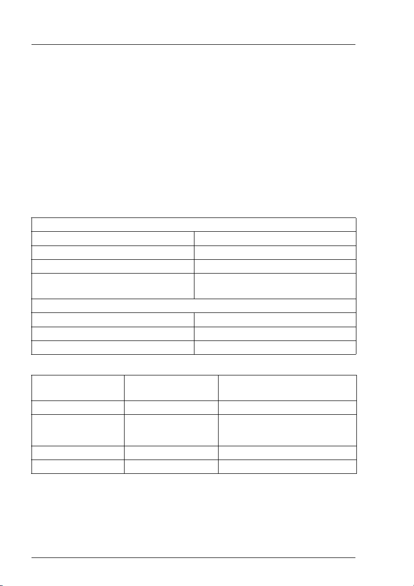
1.4 Technical Data
Electrical Characteristics
Rated voltage 100 V - 240 V
Tolerance of the rated voltage +6 % / -10 %
Rated frequency 50 Hz / 60 Hz
Rated current max. 1.3 A at 240 V
max. 3.1 A at 100 V
Power consumption
Active power (= heat transfer) max. 305 W
Apparent power max. 310 VA
Power factor (PF) 0.95-0.99
Dimensions and
Floorstand model Rack model
Weight
Height 481mm 133 mm
Width 200 mm without legs
483 mm
280 mm with legs
Depth 692 mm 646 mm
Weight max. 32 kg max. 30 kg
4 U41221-J-Z156-1-74
Page 13
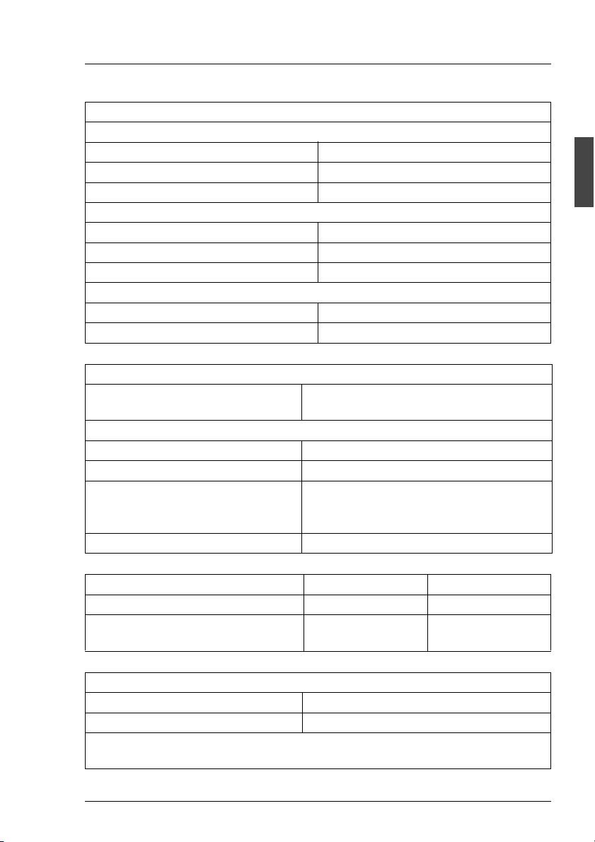
Introduction Technical Data
Environmental Conditions (according to DIN EN 60721-3-x)
Climate/operation (class 3K2):
Temperature 15 °C to 35°C
Relative humidity 5% to 85%
altitude (NN) max. 3048 m (10000 ft.)
Climate/transport (class 2K2):
Temperature -25°C to 60°C
Relative humidity 15% to 98%
altitude (NN) max. 15240 m (50000 ft.)
Mechanical environmental conditions
Operation Class 3M2
Transport Class 2M1
Standards Complied With
Product safety and ergonomics IEC 60950 (DIN EN 60950), UL 1950,
CSA 950, ZH1/618
Electromagnetic compatibility
Emitted interference EN 55022, class B; FCC part 15, class A
Noise immunity EN 50082-1
CE label Low voltage guideline
LVD 73/23/EEC
EMC guideline 89/339/EWG
Approval certification GS, CSA NRTL/C, CB certificate
Noise Development (ISO 9296) Operation Idle
Sound level (L
Workstation-related
sound pressure level (L
) max. 7.0 B max. 6.2 B
WAd
max. 56 dB(A) max. 46 dB(A)
)
pAm
Maintenance Areas and Ventilation Distances
Floorstand model Rear 400 mm, left 1200 mm *
Rack model Specified by the 19“ rack
* The area on the left need not always be kept open. However, it must be
possible to clear it without too much effort.
U41221-J-Z156-1-74 5
Page 14

Page 15

2 Important Notes
2.1 Notes on Safety
In this section you will find information that you must note when using the
storage subsystem.
This device complies with the relevant safety standards for IT equipment,
including electronic office machines, intended for use in the office environment.
I You will also find the following safety instructions in the manual entitled
“Safety, Warranty and Ergonomics“ which also includes other notes on
guarantee and ergonomics. Also pay attention to the notes in the manual
of the connected PRIMERGY system.
If you have any questions relating to setting up and operating your system in the
environment where you intend to use it, please consult our service organization.
V CAUTION!
● The actions described in these instructions should only be performed
by technicians, service personnel or technical specialists. Equipment
repairs should only be performed by qualified staff. Any failure to
observe the guidelines in this manual could expose the user to risks
(electric shock, fire hazards) and could also damage the equipment.
Note that any unauthorized opening of the device will result in the
invalidation of the warranty and exclusion from all liability.
● Transport the device in its original packaging or in other suitable
packaging which will protect it against shock or impact.
● Read the notes on environmental conditions in section “Technical
Data” on page 4 before setting up and operating the device.
● If the device is brought in from a cold environment, condensation may
form both inside and on the outside of the machine.
Wait until the device has acclimatized to room temperature and is
absolutely dry before starting it up. Material damage may be caused
to the device if this requirement is not observed.
U41221-J-Z156-1-74 7
Page 16

Notes on Safety Important Notes
V CAUTION!
● Check that the rated voltage specified on the device's ID plate is the
same as the local line voltage.
● The device must only be connected to a properly grounded wall outlet
(the device is fitted with a tested and approved power cable).
● Make sure that the protective grounded outlet of the building’s wiring
system is freely accessible.
● Switching off the device does not cut off the supply of power. To do
this you must remove the power plugs.
● Before opening the unit, switch off the device and then pull out the
power plugs.
● Route the cables in such a way that they do not form a potential
hazard (make sure no-one can trip over them) and that they cannot
be damaged. When connecting up a device, refer to the relevant
notes in this manual.
● Never connect or disconnect data transmission lines during a storm
(lightning hazard).
● Systems which comprise a number of cabinets must use a separate
fused socket for each cabinet.
● The system unit and the directly connected external storage
subsystems should be connected to the same power supply
distributor. Otherwise you run the risk of losing data if, for example,
the central processing unit is still running but the storage subsystem
has failed during a power failure.
● Make sure that no objects (such as bracelets or paper clips) fall into
or liquids spill into the device (risk of electric shock or short circuit).
● In emergencies (e.g. damage to housings, power cords or controls or
ingress of liquids or foreign bodies), immediately power down the
device, pull out the power plugs and notify your service department.
● Note that proper operation of the system (in accordance with IEC
60950/DIN EN 60950) is guaranteed only if slot covers are installed
on all vacant slots and/or dummies on all vacant bays and the
housing cover is fitted (cooling, fire protection, RFI suppression).
8 U41221-J-Z156-1-74
Page 17
Important Notes Electrostatic Sensitive Device Label
2.2 Electrostatic Sensitive Device Label
Electrostatic-sensitive components may be identified by the following sticker:
Figure 1: Electrostatic Sensitive Device (ESD) sticker
You must follow the instructions below when handling modules containing
electrostatic-sensitive components
Ê Discharge static electricity from your body (for example by touching a
grounded metal object) before handling modules containing electrostaticsensitive components.
Ê The equipment and tools you use must be free of static charge.
Ê Remove the power plug before installing or removing modules containing
electrostatic-sensitive components.
Ê Only hold modules containing electrostatic-sensitive components by their
edges.
Ê Do not touch any of the pins or track conductors on a module containing
electrostatic-sensitive components.
Ê Use a grounding strap designed for the purpose, to connect you to the
system unit as you install the modules.
Ê Place all components on a static-safe base.
I An exhaustive description of the handling of modules containing electro-
static-sensitive components can be found in “Guidelines on handling
electrostatic sensitive devices and modules (ESD)” or “ITS Circular
4/95”.
U41221-J-Z156-1-74 9
Page 18

CE certificate Important Notes
2.3 CE certificate
The shipped version of this device complies with the requirements
of the EEC directives 89/336/EEC “Electromagnetic compatibility”
and 73/23/EEC “Low voltage directive”. The device therefore
qualifies for the CE certificate (CE=Communauté Européenne).
2.4 RFI Suppression
All other equipment which is connected to this product must also have radio
noise suppression in accordance with EC Guideline 89/336/EWG.
Products which meet this requirement are accompanied by a certificate to that
effect issued by the manufacturer and/or bear the CE mark. Products which do
not meet this requirement may be operated only with the special permission of
the BZT (Bundesamt für Zulassungen in der Telekommunikation).
2.5 FCC notices (Federal Communications Commission)
Class A digital device
This equipment has been tested and found to comply with the limits for a Class
A digital device, pursuant to part 15 of the FCC Rules. These limits are designed
to provide reasonable protection against harmful interference when the
equipment is operated in a commercial environment. This equipment
generates, uses, and can radiate radio frequency energy and, if not installed
and used in accordance with the instruction manual, may cause harmful interference to radio communications. Operation of this equipment in a residential
area is likely to cause harmful interference in which case the user will be
required to correct the interference at his own expense.
10 U41221-J-Z156-1-74
Page 19

Important Notes Notes on the Rack Model
2.6 Notes on the Rack Model
● For safety reasons, at least two people are required to install the rack model
because of its weight and size.
● When connecting and disconnecting cables, observe the notes in the
documentation for your PRIMERGY system and the comments in the
“Important notes” chapter in the technical manual supplied with the rack.
● Ensure that the anti-tilt bracket is correctly mounted when you set up the
rack.
● For safety reasons, no more than one unit may be withdrawn from the rack
at any one time during installation and maintenance work.
● If more than one unit is withdrawn from the rack at any one time, there is a
danger that the rack will tilt forward.
● The connection of the rack to the mains voltage must be installed by an
authorized specialist (electrician).
2.7 Notes on Transportation
I Transport the storage subsystem in its original packaging or in other
suitable packaging which will protect it against shock or impact.
Do not unpack it until all transport maneuvers are completed.
If you need to lift or transport the storage subsystem, ask someone to
help you.
U41221-J-Z156-1-74 11
Page 20

Environmental Protection Important Notes
2.8 Environmental Protection
Environmentally friendly product design and development
This product has been designed in accordance with the Fujitsu Siemens
Computers standard for “environmentally friendly product design and development”.
This means that the designers have taken into account important criteria such
as durability, selection of materials and coding, emissions, packaging, the ease
with which the product can be dismantled and the extent to which it can be
recycled.
This saves resources and thus reduces the harm done to the environment.
Notes on saving energy
Devices that do not have to be on permanently should not be switched on until
they need to be used and should be switched off during long breaks and on
completion of work
Notes on packaging
We recommend that you do not throw away the original packaging in case you
need it later for transportation. If possible, devices should be transported in their
original packaging.
Notes on dealing with consumables
Please dispose of batteries in accordance with local regulations.
Notes on labeling plastic housing parts
Please avoid attaching your own labels to plastic housing parts wherever
possible, since this makes it difficult to recycle them.
12 U41221-J-Z156-1-74
Page 21

Important Notes Environmental Protection
Take-back, recycling and disposal
For details on take-back and reuse of devices and consumables within Europe,
contact your Fujitsu Siemens Computers branch office/subsidiary or our
recycling center in Paderborn:
Fujitsu Siemens Computers
Recycling Center
D-33106 Paderborn
Tel. ++49 5251 8180-10
Fax ++49 5251 8180-15
Further information on environmental protection
The Fujitsu Siemens Computers representative for environmental protection
will be happy to answer any further questions you may have concerning
environmental protection.
Fujitsu Siemens Computers
Referat Umweltschutz
Werner-von-Siemens-Straße 6
D-86159 Augsburg
Tel. ++49 821 804-2386
Fax ++49 821 804-2706
U41221-J-Z156-1-74 13
Page 22

Page 23

3 Operating and Indicator Elements
This section describes the position and meaning of the operating and indicator
elements on the PRIMERGY S60 storage subsystem.
3.1 The Front
You can see the following indicator elements on the front of the PRIMERGY
S60 storage subsystem
● The three operating status LEDs which indicate the power supply status, the
cooling status and the server management status.
● Control LEDs for the hard disk drives (two LEDs on each of the HDD
modules).
I There is a HDD Ready and a HDD Status LED for each of the 14
possible hard disk drives.
U41221-J-Z156-1-74 15
Page 24
The Front Operating and Indicator Elements
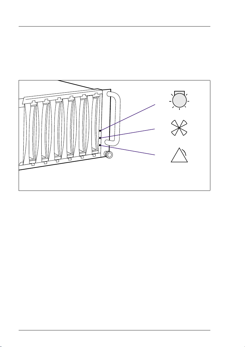
3.1.1 Meaning of the S60 Operating Status LEDs
The state of the status LEDs located on the HDD backplane is transmitted by
optical waveguides so that the power supply status, the cooling status and the
server management status are indicated on the front of the storage subsystem.
1
2
3
Figure 2: Operating Status LEDs and Icons on the Front of the Rack Model
(1) Power supply status
(2) Cooling status
(3) Server management status
!
V CAUTION!
In order to guarantee the server management for the PRIMERGY S60
storage subsystem over SES (SCSI Enclosure Service), at least one of
the two first HDD modules (see also section “Identification Marks and
Loop Addresses” on page 43) must be installed.
I Fault clearing instructions can be found in the chapter “Troubleshooting”
on page 71 of this manual.
16 U41221-J-Z156-1-74
Page 25
Operating and Indicator Elements The Front
Optical Waveguide Color Meaning
Power supply status none No mains voltage present.
green POWER OK
Equipment switched ON, all installed
power supply units OK.
yellow POWER WARNING
One power supply unit has failed.
orange STANDBY
Equipment switched OFF, mains voltage
present.
Cooling status
V CAUTION!
The PRIMERGY S60
storage subsystem
(without Remote Service
Board) switches OFF at
an interior temperature of
55°C (see section
“Cooling status LED lights
orange” on page 73).
Server management
status (global SES
indicator)
green Cooling OK
All installed fans and the interior temperature are OK.
yellow Fan warning
One fan has failed.
The temperature is OK.
orange Cooling fault
All the fans have failed or the interior
temperature exceeds the permissible
values.
none No status indication
orange Identification indication
(can be activated manually from
ServerView).
For troubleshooting see section “Server
Management Status LED lights permanently” on page 74.
Table 1: Meaning of the Operating Status LEDs Indication
U41221-J-Z156-1-74 17
Page 26
The Front Operating and Indicator Elements
3.1.2 The Control LEDs for the Hard Disk Drives
H D D R E A D Y
H D D S T A T U S
Figure 3: Symbols of the Control LEDs of the Hard Disk Drives
(HDD READY) Operating indication of the hard disk drive.
This LED is driven by the hard disk drive itself.
(HDD STATUS) Status indication of the hard disk drive.
This dual-color (yellow/orange) LED is set by the hard disk
drive itself (yellow indicator) or by the SES controller (orange
indicator).
18 U41221-J-Z156-1-74
Page 27
Operating and Indicator Elements The Front
LED Indication Meaning
HDD
READY
OFF The associated drive is not (correctly)
inserted or it is spun down and it is not
being accessed.
OFF
green intermittent
The associated drive is spun down. The
drive is being accessed.
flashes
ON
green permanently on
The associated drive is spun up and ready.
The drive is not being accessed or hot
spare drive.
ON
green intermittent
The associated drive is spun up and ready.
The drive is being accessed.
flashes
green,
flashes steadily
The associated drive is spinning up or
down (“prepare to remove” command: ca.
10 sec. flashes quickly 3 times per sec.,
followed from slowly flashes in 3 sec.
interval; see also section “Hot Swap for FC
HDD Modules” on page 42).
HDD
STATUS
OFF There is no hard disk fault.
yellow,
HDD error occurred.
permanently on
orange,
Drive identification.
flashes quickly
orange,
flashes quickly
– Drive rebuild: all drives belonging to the
pack blink synchronously.
– Error message from controller:
Critical LUN (Logical Unit Number)
– A drives was set on “Make Offline” and
the remaining HDD modules flash
quickly.
orange,
permanently on
Table 2: Meaning of the HDD Control LEDs Indication
“Make Offline” state for the selected HDD
modules.
U41221-J-Z156-1-74 19
Page 28
The Rear Side Operating and Indicator Elements
3.2 The Rear Side
On the rear side of the PRIMERGY S60 storage subsystem there are the status
LEDs for the FFx-RAID controller module(s) and for the power supply units.
Also the power switch is placed on this side.
1
6
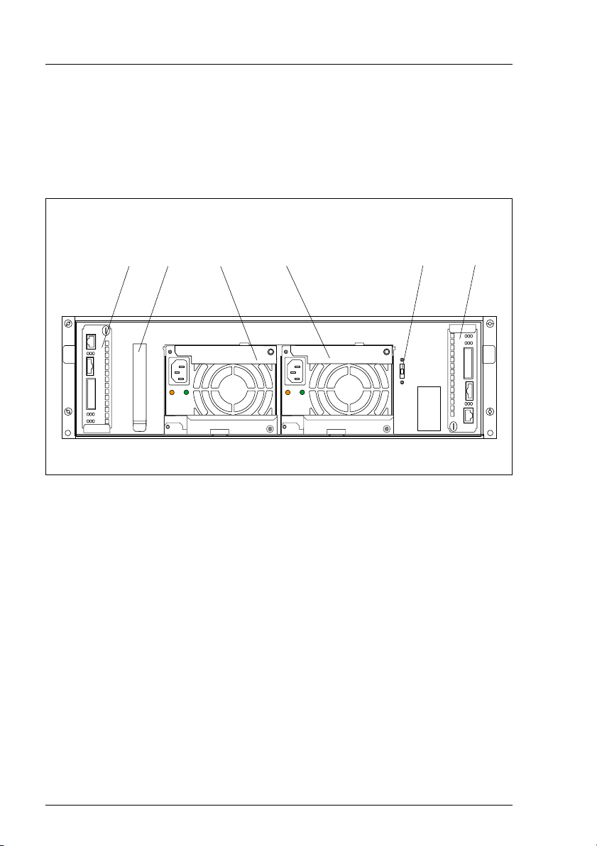
Figure 4: Rear View of the PRIMERGY S60 Storage Subsystem
(1) FFx-RAID controller module 1
(2, 3) Power supply units
(4) Power switch
(5) FFx-RAID controller module 0 (default)
(6) Location for the optional Remote Service Board
2
3 4
3.2.1 FFx-RAID Controller Module LEDs
5
The status LEDs are located on the connection panel of the FFx-RAID controller
module. For description see section “The FFx-RAID Controller Module” on
page 45.
20 U41221-J-Z156-1-74
Page 29
Operating and Indicator Elements The Rear Side
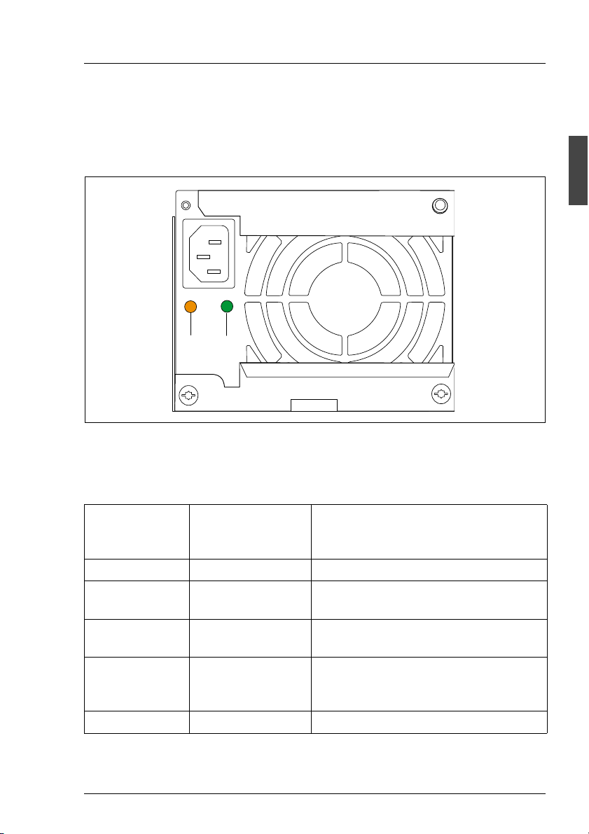
3.2.2 Power Supply Unit LEDs
On the connecting side of the power supply units there are two LEDs that
indicate the status of the power supply units:
2
1
Figure 5: The Power Supply Unit LEDs
(1) Fault indication (amber LED)
(2) Operating indication (green LED)
Fault
indication (1)
(amber LED)
OFF OFF No AC voltage present.
OFF flashing AC voltage present; standby outputs
OFF ON DC outputs ready. Power supply unit
ON OFF No AC voltage present for this power
flashing ON Current limiting.
Table 3: Meaning of the Power Supply Unit LEDs
U41221-J-Z156-1-74 21
Operating
indication (2)
(green LED)
Status of the power supply unit
ready.
operational.
supply unit or power supply unit has
failed.
Page 30

The Rear Side Operating and Indicator Elements
3.2.3 Power Switch
The power switch is located also on the rear of the PRIMERGY S60 storage
subsystem. It is a slide switch with three possible settings.
I
R
O
Figure 6: Power Switch on the Rear of the PRIMERGY S60 Storage Subsystem
Position Function Description
(I) local ON The storage subsystem is switched ON permanently
and is connected directly to the mains (default
setting).
(R) The operating mode (on/off) is controlled via the Remote Service
Board. In this default setting, the storage subsystem is switched
on and off simultaneously with the server. If two servers are
connected, it remains active as long as one of the servers is
switched on.
(O) OFF The storage subsystem is switched OFF permanently.
Table 4: Possible Settings of the Power Switch
22 U41221-J-Z156-1-74
Page 31

Operating and Indicator Elements Fan LED
3.3 Fan LED
If you have been notified, via corresponding warning or error messages on the
server or via the cooling status LED on the front of the storage subsystem, that
there is a cooling problem, the fan status can be read on the fan LED.
1
Figure 7: Installed Fan Module, View with Fan LED
(1) Fan LED
Color Meaning Required Measures
green Both fans are in operation. No action required.
yellow One fan has failed. The fan module must be replaced.
orange Both fans have failed. The fan module must be replaced.
Table 5: Meaning of the Fan LEDs
I Replacement of the fan module is described in the chapter “Fan Module”
on page 33.
U41221-J-Z156-1-74 23
Page 32

Page 33

4 Floorstand Model
4.1 Open the Housing
4.1.1 Removing and Mounting the door
!
1
Figure 8: Removing the Door
2
Ê Unlock the door with the key (1) and open it.
Ê Remove the door by lifting it up (2).
Mounting is performed in the reverse order.
U41221-J-Z156-1-74 25
Page 34

Open the Housing Floorstand Model
4.1.2 Removing/Mounting the left Side Cover
I To replacing the fan module (see section “Installing/Removing the Fan
Module” on page 34) in the floorstand model the left side cover must be
removed.
3
2
1
Figure 9: Removing the Side Cover
Ê Open the door.
Ê Loosen the lower left knurled screw (1) and slide the left side cover in the
direction of the arrow for approx. 3cm (2).
Ê Remove the side cover from the six guides by sliding it in the direction of the
arrow marked (3).
26 U41221-J-Z156-1-74
Page 35

Floorstand Model Open the Housing
Mounting is performed in the reverse order.
V CAUTION!
For mounting the left side cover pay attention to the connection strip (1)
for the door switch (see figure 10). It can be damaged.
1
Figure 10: Floorstand model: door switch with connection strip
U41221-J-Z156-1-74 27
Page 36

Page 37

5Power Supply
5.1 Power Supply Units
The PRIMERGY S60 storage subsystem contains two power supply units which
guarantee the power supply to all installed components.
Using two power supply units, power supply redundancy is achieved. If a power
supply unit fails, the subsystem will continue to operate without restrictions.
I To guarantee a power supply unit redundancy, a failed power supply unit
must be replaced urgently.
The power supply units are supplied with mains voltage via the supplied
connecting cables.
The power supply units can be connected directly to two different phases of the
in-house circuit in order to achieve phase redundancy (see section “Mains
Connection with Phase Redundancy” on page 59).
U41221-J-Z156-1-74 29
Page 38

Power Supply Units Power Supply
5.1.1 Replacing the Power Supply Unit
V CAUTION!
It is imperative that you read the chapter “Important Notes” on page 7 in
this manual before you carry out work on your storage subsystem.
If faults occur with the power supply, it could be necessary to replace a power
supply unit. Information about the relevant error messages can be found in the
sections “Meaning of the S60 Operating Status LEDs” on page 16, “Power
Supply Unit LEDs” on page 21 and in the chapter “Troubleshooting” on page 71.
Figure 11: Power Supply Unit Removed
V CAUTION!
When a power supply unit is replaced in a non-redundant power supply
system (only one power supply unit present) the server must be
switched OFF and/or the FC channels deactivated.
Ê If only one power supply unit is present, shut down the server and switch it
OFF.
Ê Remove the cable of the defective power supply unit.
Ê Raise the lower catch on the power supply unit and carefully remove it from
its slot by pulling on the upper catch. To remove the power supply unit the
lower catch must be in the up position.
30 U41221-J-Z156-1-74
Page 39

Power Supply Power Supply Units
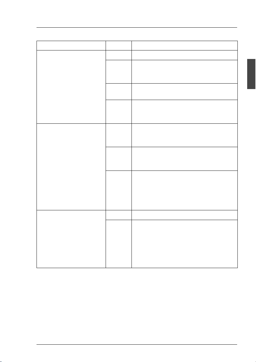
Installing occurs in reverse of order:
1
Figure 12: Power Supply Unit Removed with Coding Pin
Ê Push the new power supply unit into the empty slot.
I Please note the coding of the power supply unit. Only one power
supply unit, to which the coding pin (1) is attached in such a way that
it does not adversely affect the installation, may be used in the
PRIMERGY S60 storage subsystem. The coding may not be
removed under any circumstances.
V CAUTION!
Please ensure that the power supply unit engages correctly in the
mounting frame and is locked in position. This is the only way to avoid
the power supply unit being shaken out of its mountings and
damaged during transport.
Ê Connect the cable to the power supply unit (see the section “Mains
Connection” on page 58).
Ê Connect the power cable to the mains (see section “Mains Connection” on
page 58).
U41221-J-Z156-1-74 31
Page 40

Page 41

6 Fan Module
The redundant fan module ensures cooling of the PRIMERGY S60 storage
subsystem. It is equipped with two fans. If one fails, the other working fan sufficiently guarantees cooling and prevents the components of the storage
subsystem from overheating.
A temperature sensor on the rear panel of the power supply unit and a
revolution monitor fitted for each fan are used to permanently check the cooling.
Error messages can be read on the cooling status LED on the front of the
storage subsystem (see section “Meaning of the S60 Operating Status LEDs”
on page 16) and on the fan LED (see section “Fan LED” on page 23).
As soon as fan failure is detected, the fan module with the defective fan should
immediately be replaced with an intact module so that the redundancy characteristics (availability) are retained.
I Only the complete fan module may be replaced.
I The fan module can be replaced during operation.
V CAUTION!
The fan module should be replaced within 30 seconds to prevent
possible overheating.
U41221-J-Z156-1-74 33
Page 42

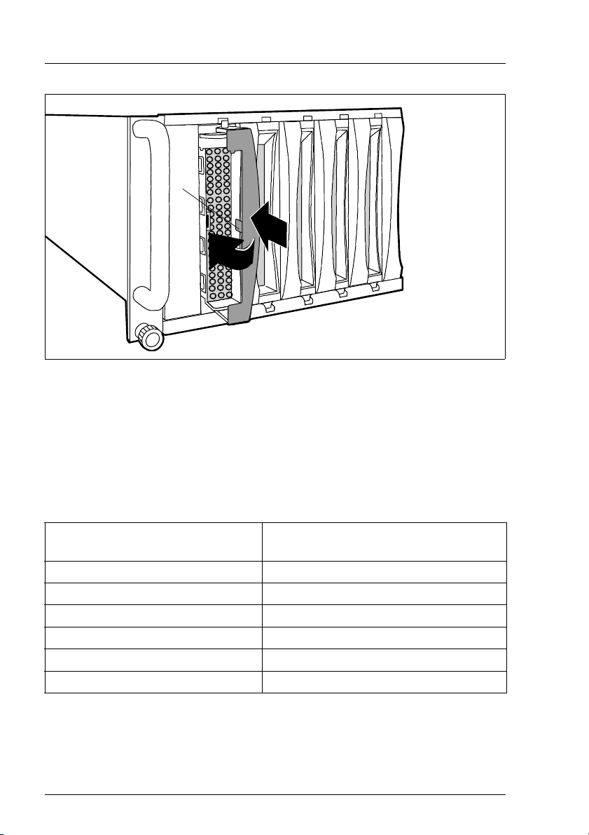
Installing/Removing the Fan Module Fan Module
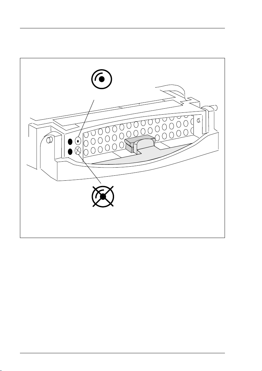
6.1 Installing/Removing the Fan Module
I Please note the status of the fan LED before removing and after installing
the fan module (3) (see section “Fan LED” on page 23).
Floorstand model
Ê Remove the left side cover (see section “Removing/Mounting the left Side
Cover” on page 26).
Rack model
Ê Loosen the two knurled screws on the front of the rack model and pull out
the storage subsystem from the rack.
2
1
1
4
3
Figure 13: Releasing and Removing the Fan Module
Ê Release the fan module by putting two fingers into the recessed grips and
push the locking mechanisms found here inwards (1).
V CAUTION!
Note the warning label “Rotating Parts“ (4) on the fan module. There
is an increased risk of injury from rotating parts.
Ê Remove the fan module from the storage subsystem in the direction of the
arrow (2).
34 U41221-J-Z156-1-74
Page 43

Fan Module Installing/Removing the Fan Module
Proceed as follows when installing the fan module:
2
1
1
Figure 14: Installing the Fan Module
Ê Put two fingers into the recessed grips (1). When installing, it is not
necessary to push the locking mechanism inwards.
Ê Lift the fan module over the slot and insert it carefully (2).
Ê Gently push the fan module down until you can feel and hear it engaging.
U41221-J-Z156-1-74 35
Page 44

Page 45

7 FC Hard Disk Drives
Up to fourteen one inch hard disk drives can be installed into the
PRIMERGY S60 storage subsystem. The FC hard disk drives can be controlled
via up to two FC ports. The two FC ports are in each case over two outward lead
Nodes in one loop. This means that each port is in one FC Loop (all ports A
from the FC hard disk drives are in the same loop as the channel 0 from (both)
FFx-RAID controller(s) and all ports B from the FC hard disk drives are in the
same loop as the channel 1 from (both) FFx-RAID controller(s)).
The FC hard disk drives are built on a carrier which allows defective drives to
be replaced (hot swap) or new drives to be added during operation. The hard
disk drive and the carrier constitute the hard disk drive module (HDD module).
The hot-swap function can only be performed together with a corresponding
RAID configuration. Further information about the RAID configuration or RAID
level can be found in the RAID controller documentation.
A hard disk drive may only be replaced if it is inactive (see description of the
LEDs in the table “Meaning of the HDD Control LEDs Indication” on page 19) or
if it has been marked as defective in the management tool.
The hot swap procedure increases the availability of the system operation and
guarantees a high degree of data integrity and protection against failure.
7.1 Handling Hard Disk Drives/HDD Modules
Hard disk drives incorporated in the HDD modules are highly sensitive electromagnetic devices and must be handled with great care. It is extremely likely that
an incorrect handling will lead to a partially and/or total failure of the hard disk
drives.
These failures will result in data errors and to loss of data or to total destruction
of the hard disk drive.
Please observe following rules, which will help to avoid the occurrence of this
type of problems:
● Store and transport HDD modules only within the limits stipulated in the
specification.
● When transporting HDD modules (even over short distances), always use
the original packaging (ESD labeling).
U41221-J-Z156-1-74 37
Page 46

Installing/Removing HDD/Dummy Module FC Hard Disk Drives
● Never expose a HDD module to a temperature shock. Avoid the formation
of condensation inside and on the outside of the hard disk drives.
The hard disk drives may be expose only to defined temperature and
climatic conditions.
● Always put the HDD module down carefully, with its largest surface facing
downwards, to avoid the danger of tipping over.
7.2 Installing/Removing HDD/Dummy Module
V CAUTION!
Under no circumstances should you remove a HDD module while the
system is in operation if you are not sure that the hard disk drive is
operated by a RAID controller and belongs to a disk array which is
operating in RAID level 1 or 5.
V CAUTION!
The HDD modules must all be marked clearly (see also section “Identification Marks and Loop Addresses” on page 43) so that they can be put
back into the original slots after an upgrade. If this is not taken into
account, existing data can be destroyed.
The hard disk drives which can be ordered for the PRIMERGY S60 storage
subsystem are delivered as HDD modules which include the hard disk drive preinstalled in a carrier. Only a service technician may remove a hard disk drive
from the carrier.
Free slots are provided with a dummy module (an empty carrier) which must be
removed before installing an additional HDD module.
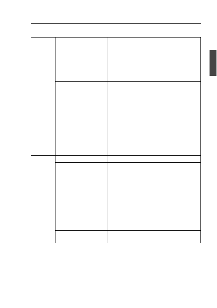
Removing the dummy module
Ê Press the upper and lower tabs on the dummy module together (see
figure 15 on page 39) until the locking mechanism disengages, and remove
the dummy module from the slot.
Installation of the dummy module occurs in reverse order.
38 U41221-J-Z156-1-74
Page 47

FC Hard Disk Drives Installing/Removing HDD/Dummy Module
Figure 15: Dummy Module and corresponding HDD Module
V CAUTION!
Keep the dummy module for future use. If the HDD module is removed
again and not replaced with a new module, then the dummy module must
be reinstalled due to cooling, the applicable EMC (electromagnetic
compatibility) regulations and fire protection.
Installing the HDD module
Ê Solve the locking mechanism by pressing the locking button (1) .
Ê Push the handle of the HDD module fully in the direction of the arrow.
U41221-J-Z156-1-74 39
Page 48
Installing/Removing HDD/Dummy Module FC Hard Disk Drives
3
1
2
Figure 16: Installing the HDD Module
Ê Push the HDD module into the empty slot (1) until it stops .
Ê Push the module handle completely in the direction of the arrow (2) until the
locking mechanism (3) engages.
V CAUTION!
The HDD module must be acclimatized in its operating environment for
an acclimatization time.
Temperature difference (°C)
(operating environment/outside)
53
10 5
15 7
20 8
25 9
30 10
Table 6: Acclimatization Time for the HDD Module
40 U41221-J-Z156-1-74
Minimum acclimatization time
(hours)
Page 49

FC Hard Disk Drives Installing/Removing HDD/Dummy Module
Removing occurs in reverse order:
1
Figure 17: Removing the HDD Module
Ê Pull out the HDD module. Observe the notes in the section “Handling Hard
Disk Drives/HDD Modules” on page 37.
U41221-J-Z156-1-74 41
Page 50

Hot Swap for FC HDD Modules FC Hard Disk Drives
7.3 Hot Swap for FC HDD Modules
V CAUTION!
The hot-swap function can only be performed together with a corresponding RAID configuration.
Only pull out a HDD module if the drive is not being accessed. Observe
the control LEDs for the corresponding HDD module (see section “The
Control LEDs for the Hard Disk Drives” on page 18).
If you want to replace an FC HDD module during operation, proceed as follows:
Ê If you want to pull out a HDD module which is not defective, it must be set to
“Offline“ via software (RAID controller configuration software), and/or it must
be prepared for removal by the “prepare to remove” command.
Ê Pull out the HDD module (defective/not defective) by a few centimeters.
Ê Wait for at least 60 seconds.
I This period is necessary for the RAID controller to recognize that a
HDD module has been pulled out and for the hard disk drive to come
to a stop.
Ê Pull out the HDD module right.
Ê Insert the new HDD module.
When you have removed the HDD module and are not replaced with a new
module, then insert a dummy module into the empty slot. Ensure that the
dummy module engages in the slot correctly.
42 U41221-J-Z156-1-74
Page 51

FC Hard Disk Drives Identification Marks and Loop Addresses
7.4 Identification Marks and Loop Addresses
The identification of the hard disk drives with marks as HDD1 through HDD14
must be performed from the bottom up (floorstand model) or from left to right
(rack model).
The loop addresses of the FC hard disk drives are hardware-predefined as
follows:
HDD 1234567891011121314
ID (Dec.) 012 3 45678910111213
ID (hex) 00 01 02 03 04 05 06 07 08 09 0A 0B 0C 0D
Table 7: Address IDs
U41221-J-Z156-1-74 43
Page 52

Page 53

8 Plug-in Board Modules
8.1 The FFx-RAID Controller Module
The module will be inserted in an individual slot on the rear of the storage
subsystem. The two modules in figure 4 on page 20 are marked (1) for the FFx-
RAID controller module 1 and (5) for the FFx-RAID controller module 0.
V CAUTION!
In a simplex configuration the storage subsystem can be accessed only
via the FFx-RAID controller module 0 (see figure 4 on page 20).
In a dual-active configuration both FFx-RAID controller modules must have the
same size of cache memory and the same firmware version.
The module incorporates the FFx-RAID controller itself (1), the device adapter
(DA) (2) and the host adapter (HA) (3).
1 2 3 4
1 2 3 4
O N
O N
2
Figure 18: The FFx-RAID controller module
1
3
The FFx-RAID controller is a high-performance FC host to FC disk array
controller. The device adapter makes the connection between the FFx-RAID
controller and the FC hard disk drives, the host adapter the connection to the
server.
U41221-J-Z156-1-74 45
Page 54

The FFx-RAID Controller Module Plug-in Board Modules
8.1.1 Indicators and Connectors
The integrated FC-HUB provides the standard host-interface (two nodes) for
the storage subsystem. One node will be connected via a fixed HSSDC
connector (11) (see figure 19 on page 47) available only for cooper cable up to
10 m.
The other node will be connected via a GBIC (Gigabit Interface Converter) (12).
The FC-transmission medium (CU/HSSDC, MMF or SMF) depends on the type
of GBIC being used.
I Perfect functioning will be ensured only by the use of the GBIC types
released by Fujitsu Siemens Computers GmbH.
LEDs indicate the operating status of the module, of the corresponding nodes
and/or loop and the channel activity (see tables under „Description of the LED
indicators“ on the following pages).
To configure the FFx-RAID controller, use the VT100 Terminal-EmulationInterface (see “Related publications” on page 81) or SAM (SAN Array Manager)
software. The VT100 Terminal-Emulation-Interface can be connected via the
VT100-DEBUG connector (10).
46 U41221-J-Z156-1-74
Page 55

Plug-in Board Modules The FFx-RAID Controller Module
Following indicators and connectors are located on the connection panel of the
module (figure 19):
No. Element Label on the connection panel
1 LED green 1 DAC DEVICE ACTIVITY
2 LED yellow/green 2 VT100/DEBUG STATUS
3 LED yellow/green 3 HSSDC NODE STATUS
4 LED green 4 DAC HOST ACTIVITY
5 LED yellow/green 5 DAC NODE STATUS
6 LED yellow/green 6 GBIC NODE STATUS
7 LED yellow 7 CACHE
8 LED green 8 DAC STATUS
9 LED red 9 DAC POWER ALARM
10 VT100-DEBUG connector VT100/DEBUG
11 HSSDC connector HSSDC NODE
12 GBIC connector GBIC NODE
1 D A C D E V I C E A C T I V I T Y
2 V T 1 0 0 / D E B U G S T A T U S
D A C
V T 1 0 0 / D E B U G H S S D C N O D E G B I C N O D E
3 H S S D C N O D E S T A T U S
1
2
3
1 0
4 D A C H O S T A C T I V I T Y
5 D A C N O D E S T A T U S
6 G B I C N O D E S T A T U S
1 1 1 2
7 C A C H E
8 D A C S T A T U S
9 D A C P O W E R A L A R M
4
5
6
7
8
9
Figure 19: FFx-RAID Controller Module / Connectors and Indicators
U41221-J-Z156-1-74 47
Page 56

The FFx-RAID Controller Module Plug-in Board Modules
Description of the LED indicators
LED
7
CACHE
(yellow)
OFF ON OFF Normal operation, module ready and partner
8
DAC
STATUS
(green)
9
DAC
POWER
ALARM
(red)
Description
OK
I This signal is activated only if two
FFx-RAID controller modules are
used; only the non-defective module
can indicate that the other one has
failed.
OFF flashing
0.5 sec.
OFF flashing
1 sec.
OFF Normal operation, FFx-RAID controller
module not ready and partner OK.
OFF Normal operation, FFx-RAID controller
module ready and partner failed
I This signal is activated only if two
FFx-RAID controller modules are
used; only the non-defective module
can indicate that the other one has
failed.
OFF OFF ON Alarm:
FFx-RAID controller not powered (5 VDC;
3.3 VDC)
OFF OFF flashing
0.5 sec.
OFF OFF flashing
1 sec.
ON OFF OFF Cache dirty:
flashing
0.5 sec.
flashing
0.5 sec.
Table 8: FFx-RAID Controller Module: Status Indicators
OFF OFF Conservative Cache activated (DIP switch
flashing
0.5 sec.
flashing
0.5 sec.
Alarm:
FFx-RAID controller 5 VDC failed
Alarm:
FFx-RAID controller 3,3 VDC failed
Data in cache and on the hard disk drives
are not identical (cache active)
K1 see “DIP Switches” on page 51)
Diagnosis Mode activated (DIP switch J1
see “DIP Switches” on page 51)
48 U41221-J-Z156-1-74
Page 57

Plug-in Board Modules The FFx-RAID Controller Module
LED
1
DAC DEVI CE
ACTIVITY
(green)
4
DAC HOST
ACTIVITY
(green)
Description
-- OFF No FC channel activity on the host side
-- ON FC channel activity on the host side
OFF -- No FC channel activity on the device side
ON -- FC channel activity on the device side
Table 9: FFx-RAID Controller Module: FC channel Activity Indicators
LED
DAC (5); GBIC (6);
HSSDC (3)
NODE STATUS
Description
(yellow/green)
green yellow
OFF OFF Module not inserted or not powered
ON OFF Full Operation: node in the loop active
OFF ON Node not in the loop (generally). Possible causes
on GBICs:
GBIC HW-Error status signals active:
RX_LOS, i. e. the received signal is not valid, or
TX_FAULT, i. e. sender works not correctly
OFF flashing
Node disabled from Service Processor (RSB)
0.5 sec.
ON ON
flashing between green
and yellow
Module OK; missing or corrupted data
approx. 0.5 sec.
Table 10: FFx-RAID Controller Module: Node Status Indicators
U41221-J-Z156-1-74 49
Page 58

The FFx-RAID Controller Module Plug-in Board Modules
LED
VT100/DEBUG STATUS
(3b yellow/green)
green yellow
flashing between green
and yellow
approx. 0.3 sec.
OFF ON RS232 switch* on position “1” (ext) and “debug
OFF flashing
2 sec.
ON OFF RS232 switch* on position “2” (RSB) and “debug
flashing
0.5 sec.
* The switches will be described in the section “Switches”.
Table 11: RS232 and FFx Status Indicators-
OFF RS232 switch* on position “2” (RSB) and “debug
Description
Voltage OK, FFx-RAID controller ready
mode” not activated
RS232 switch* on position “1” (ext) and “debug
mode” activated
mode” not activated
mode” activated
8.1.2 Switches
The RS232 Switch
This switch (figure 20 on page 51) enables the RS232-FFx receiver to be
switched between an external (default) and an internal (service processor on
the Remote Service Board) means of control.
Pos. Description
1 ext. RS232 (default)
The external controlling means will be attached via the VT100/DEBUG
connector (see figure 19 on page 47).
2RSB
Internal controlling means via the service processor on the optional
Remote Service Board.
I When the PRIMERGY S60 storage subsystem operates without
the optional Remote Service Board the switch must be set on
position “1”.
Table 12: RS232 switch settings
50 U41221-J-Z156-1-74
Page 59

Plug-in Board Modules The FFx-RAID Controller Module
K 1 - K 4
O N
D I P s w i t c h
4
3
1 2
1 2 3 4
ON
J 1 - J 4
4
3
1 2
O N
1 2 3 4
ON
R S 2 3 2 s w i t c h
2
1
Figure 20: FFx-RAID Controller Module: Switches on the Host Adapter
DIP Switches
DIP switches J1-J4 and K1-K4 (functionality switches) for the setting test and
analyzing possibilities in arrangement with the service are available on the host
adapter.
For normal operation the DIP switches J1-J4, K1, K2 and K4 must be set to
OFF, the DIP switch K3 to ON.
U41221-J-Z156-1-74 51
Page 60
The FFx-RAID Controller Module Plug-in Board Modules
The individual DIP switch positions ON have the following function:
DIP switch Function
J1 ON Manufactory Diagnosis Mode activated: status indicator LEDs
(red, green, yellow) for the FFx-RAID controller flash 0.5 sec.
J2 ON Debug Mode
J3 ON Disable HSSDC NODE
J4 ON Disable GBIC NODE
K1 ON Conservative Cache active
K2 ON Enable delayed FFx-RAID controller power ON (delay ca. 17 sec.)
K3 ON Enable/Reset FFx-RAID controller from I2C bus active
K4 ON Multi Frame Mode: node ON/OFF after 4 consecutive erroneous
or error-free frames
Table 13: DIP Switches: Functions
8.1.3 Installing/removing the FFx-RAID controller module
V CAUTION!
Observe the notes on safety and the information on electrostatic
sensitive device labeling in chapter “Important Notes” on page 7.
The FFx-RAID controller module can be installed and removed while the
subsystem is running provided that the configuration involved is a dual-active
configuration (two modules with dual-active configuration have been installed)
and the MultiPath software is active. If one FFx-RAID controller module is
removed, the second module automatically takes over its function (hot swap).
V CAUTION!
As condition for a hot swap action the replaced FFx-RAID controller
modules (FFx-RAID controller) must have the same firmware version
and the same cache memory size.
52 U41221-J-Z156-1-74
Page 61

Plug-in Board Modules The FFx-RAID Controller Module
I Refer also to the MultiPath software requirements for the FFx-RAID
controller settings, e. g.: both controller must be configured identically.
In a single-mode configuration (with only one module installed), the storage
subsystem must be turned OFF before removing the module.
Ê Remove all connection cables from the FFx-RAID controller module
connectors.
Figure 21: Loosening the Knurled Screw
Ê Loosen the knurled screw on the FFx-RAID controller module.
U41221-J-Z156-1-74 53
Page 62

The FFx-RAID Controller Module Plug-in Board Modules
Figure 22: Removing the Module
Ê Carefully pull out the FFx-RAID controller module from the slot. Grasp the
module on the knurled screw and on the bracket so that it does not tilt.
Installing occurs in reverse order:
Ê Make sure that the FFx-RAID controller module engages correctly in the
plug connection on the HDD backplane.
8.1.4 Adding a Second FFx-RAID Controller Module
I The addition of a second FFx-RAID controller module may be carried-out
when upgrading the simplex configuration to a dual-active configuration.
The action cannot be accomplished during normal operation.
In a dual-active configuration, the two FFx-RAID controller modules must
accept each other as partners. This requires both modules to have the same
FW status and the same cache configuration.
Ê Check (with SAM software) whether the FW status of the existing FFx-RAID
controller module matches that of the new FFx-RAID controller module.
Ê If the FW statuses do no match, use the SAM software to load the firmware
with the status of the new FFx-RAID controller module onto the existing
FFx-RAID controller module.
54 U41221-J-Z156-1-74
Page 63

Plug-in Board Modules The FFx-RAID Controller Module
Ê Install the second FFx-RAID controller module in the free slot as module 1
(see figure 4 on page 20).
Ê Switch the storage subsystem OFF and ON again.
Ê Configure both FFx-RAID controller modules identically.
Ê Reboot the host system.
8.1.5 The FFx-BBU (Battery Backup Unit) Module
The purpose of the FFx-BBU module is to provide AC glitch ride-through
wherein power loss is momentary for maintaining cache data content.
A short power loss cycle may result in loss of FFx-RAID controller availability
while the controllers re-boot. The FFx-BBU module guaranties that in this time
no cache memory data will be lost.
Depending on the cache memory size and the battery condition the
FFx-BBU module is capable to maintaining cache memory content for many
hours.
V CAUTION!
The FFx-BBU module is not intended to protect memory contents in the
event of accidental removal while the FFx-RAID controller module is in
operation. A normally operating FFx-RAID controller module should be
shut down prior to removal from the system.
U41221-J-Z156-1-74 55
Page 64

The FFx-RAID Controller Module Plug-in Board Modules
Conditioning the Battery
Prior to beginning normal operation, it is recommended that you condition the
battery for maximum longevity.
I During the conditioning, the FFx-RAID controller will be in write-through
cache mode. This may slow normal operations. Therefore, schedule this
operation accordingly.
To ensure that the battery is fully charged and properly conditioned:
Ê From SAM software, select Administration/Intelligent BBU.
Ê Make sure the % Charge Level is 100. If the battery is currently charging, do
not continue until the Charge Level is 100%.
Ê Select Recondition Battery and Apply.
Refer to the SAM software documentation (see “Related publications” on
page 81) for more information.
56 U41221-J-Z156-1-74
Page 65

9 Connections
If you would like to put the PRIMERGY S30 storage subsystem into operation,
the FC and the mains connections must be attached.
1 2
Figure 23: The Terminals on the Rear Panel
(1) FC connection (module 1)
(2) Mains connection 2
(3) Mains connection 1
(4) FC connection (module 0)-default
3
4
U41221-J-Z156-1-74 57
Page 66

Fibre Channel (FC) Connection Connections
9.1 Fibre Channel (FC) Connection
The required connectors are on the connection panel of the corresponding
FFx-RAID controller module at the rear of the storage subsystem (see figure 19
on page 47).
The possibilities to configure and connect the storage subsystem are described
in an additional manual (“PRIMERGY S60 Technical Configuration Guide”,
see“Related publications” on page 81).
Ê Set up the data connection between the system unit and the storage
subsystem by connecting the plug on the cable from the system unit with the
corresponding FC connector of the storage subsystem.
I Pay attention that the plug is securely attached to the FC connector. Only
in this way a smooth data transfer between the system unit and the
storage subsystem can be ensured.
9.2 Mains Connection
The storage subsystem is supplied with the mains voltage via the delivered
power cables.
2
2
1
1
Figure 24: Connecting the Power Cable
Ê Plug the end of the power cable marked (1) into the socket of the power
supply unit on the rear of the storage subsystem.
58 U41221-J-Z156-1-74
Page 67

Connections Mains Connection with Phase Redundancy
Ê Plug the end of the power cable marked (2) into a properly grounded power
outlet of the in-house mains or into the mains socket strip of the rack.
I Ensure that the power outlet used to connect the storage subsystem is
adequately protected with a 16 A or 15 A (USA) automatic circuit
breaker.
9.3 Mains Connection with Phase Redundancy
In order to provide phase redundancy in the power supply of the subsystem,
each of the power supply units are directly connected either to two different
phases or to two different power circuits of in-house mains.
2
1
Figure 25: Mains Connection with Phase Redundancy
Ê Connect one end of each power cable marked (1) to one of the power supply
units of the storage subsystem.
Floorstand Model
Ê Connect the ends of the power cables marked (2) to two different phases or
to two different circuits of the in-house mains.
Rack Model
Ê Connect the ends of the power cables marked (2) to two different phases of
the mains socket strip of the rack.
U41221-J-Z156-1-74 59
Page 68

Power connection via UPS Connections
9.4 Power connection via UPS
The availability of the storage subsystem can be improved further by using
Uninterrupted Power Supplies (UPS) and/or a Redundant PowerSwitch.
I IWhen the PRIMERGY S60 works in the higher performance Cache
Write Back mode, you should use a APC UPS to secure the cache
contents (256 MB).
In such cases, the storage subsystem is connected to one of the outlets of the
UPS or to the Redundant PowerSwitch. It is generally advisable to connect both
the server and the storage subsystem to a shared UPS.
A further possibility to secure the PRIMERGY S60 storage subsystem against
power failure is given by the following configuration:
– one power supply unit is connected via an UPS
– the second power supply unit is connected directly (without UPS) to the
same phase as the UPS
If a power failure occurs the UPS will secure the first power supply unit, the
second (unsecured) power supply unit will fail. This failure causes the FFx-RAID
Controller to switch into the degraded mode and the current cache content will
be secured (duration approx. 5 minutes).
The power supply unit secured over UPS is able to supply the subsystem alone
with current. Further data accesses on the storage subsystem are executed
however, without cache memory of the controller and are written directly on the
hard disks. Data security is ensured if the duration of the power failure is such
that the UPS switches the subsystem OFF.
If power failure is restored briefly (before the subsystem was switched OFF),
then the failed second power supply unit again becomes active and the
degraded mode of the FFx-RAID Controller is deactivated.
I Phase redundancy can be easily achieved by the additional use of a
Redundant PowerSwitch.
60 U41221-J-Z156-1-74
Page 69

10 Installation
10.1 Installation Steps
V CAUTION!
The storage subsystem should not be subjected to any extreme environmental conditions (see section “Technical Data” on page 4). Protect it
from dust, moisture and heat.
The storage subsystem must be acclimatized in its operating
environment for an acclimatization time.
Temperature difference (°C)
(operating environment/outside)
53
10 5
15 7
20 8
25 9
30 10
Table 14: Acclimatization Time
The following installation steps are described in detail in other sections of this
chapter:
● Unpacking the storage subsystem.
● Setting up the floorstand model or mounting the rack model into the rack.
● Cabling the storage subsystem (see chapter “Connections” on page 57).
● Setting the desired system parameters.
● Connecting the storage subsystem to the mains voltage (see section “Mains
Connection” on page 58 or section “Mains Connection with Phase Redundancy” on page 59).
● Switching ON the storage subsystem.
Minimum acclimatization time
(hours)
U41221-J-Z156-1-74 61
Page 70

Unpacking the Storage Subsystem Installation
10.2 Unpacking the Storage Subsystem
V CAUTION!
Please note the safety instructions in chapter “Important Notes” on
page 7.
If you need to lift or transport the storage subsystem, ask someone to
help you.
You should retain the original packaging of the storage subsystem for possible
further transport.
Ê Unpack all the individual parts.
Ê Check the contents of the package for visible transport damage.
Ê Check whether the delivery matches the information given on the delivery
note.
Ê Check whether the first page of the guarantee booklet has been completed
in full.
If you find transport damage or inconsistencies between the contents of the
package and the delivery note, inform your supplier immediately!
10.3 Setting Up the Floorstand Model
Position the storage subsystem at the intended location.
Note the following:
– The device must be protected against direct sunlight.
– The required minimum distances for operation and maintenance areas must
be adhered to.
– In order to connect the server, the rear of the storage subsystem must be
accessible.
– The mains plug must be accessible easily and safely.
– To ensure sufficient ventilation of the storage subsystem, a minimum
clearance of 200 mm must be provided at the front and rear of the storage
subsystem.
62 U41221-J-Z156-1-74
Page 71

Installation Mounting the Rack Model
10.4 Mounting the Rack Model
V CAUTION!
Please take note of the safety information and the notes on mounting in
the rack in the chapter “Important Notes” on page 7.
At least two people are needed to position the storage subsystem in the
rack.
The rack may tip over if more than one heavy unit (e.g. PRIMERGY
K400) is removed.
For mounting the subsystem in the DataCenter Rack at first a support bracket
must be mounted on the rear left support upright of the DataCenter Rack. This
support bracket is used for the rear fixing of the left slide rail and must be
mounted level with the lower edge of the subsystem. Cage nuts and/or spring
nuts also must be inserted in the support uprights. The cage nuts are used for
fixing the support bracket and the subsystem, the spring nuts for fixing the slide
rails.
Ê Take the installation instruction in the Technical Manual for the corre-
sponding rack model for aid.
Ê Using the mounting aid (stencil) mark the position of the attachment points
of the storage subsystem on the support uprights (three height units).
Refer to the information on the mounting aid.
Ê Mark the mounting points of the subsystem (knurled screws on the front) on
the front support upright. Also mark the fastening points of the slide rails on
the inside grooves of the support uprights facing backwards. The bottom
edge of the fastening flange must be flush with the top housing cover of any
device already mounted.
Ê Place the cage nuts and/or the spring nuts in the groove of the support
uprights and/or of the support bracket at the marked attachment points. If
necessary, adjust the position of the nuts in the groove until they lock into
the correct position.
Ê If required, you can mount one additional cable clip for vertical cable routing.
U41221-J-Z156-1-74 63
Page 72

Mounting the Rack Model Installation
10.4.1 Preparing the Slide Rails
Before the slide rails can be screwed to the support uprights, a holding-down
clamp must be secured to each slide rail. Seen from the front of the rack, the
holding-down clamps are secured to the front area of the slide rails. They
prevent the storage subsystem from tilting down on removing it from the rack.
1
2
1
2
3
4
Figure 26: Securing the Support brackets to the Slide Rails
Ê Position the slide rails (1) on your work surface in the same way as they are
to be mounted in the rack, with the longer angular edge onto which the
storage subsystem will be placed at the bottom and on the inside.
Ê Position the holding-down clamps (2) on the slide rails from the outside so
that the drilled holes for your assembly match up on the slide rails and on
the holding-down clamps.
Ê For each holding-down clamp, insert two of the screws supplied (3) from the
inside through the drilled holes into the slide rails and into the holding-down
clamps and tighten the screws.
64 U41221-J-Z156-1-74
Page 73

Installation Mounting the Rack Model
10.4.2 Mounting Slide Rails
Ê Fasten the slide rails with the holding-down clamps to the cage nuts
provided on the support uprights, for this purpose, using four of the screws
supplied in the rack mounting kit for each rail.
10.4.3 Mounting the Subsystem
Ê Lift the storage subsystem onto the two slide rails at the front of the rack and
move it back on the rails so that you can work comfortably from behind on
the rear of the rack.
3
1
2
Figure 27: Rear Left Stop
Ê Fasten the stop (1) on the left rear edge of the casing box (2). The stop
prevents the storage subsystem from being pulled forwards too far since
there is resistance on the rear edge of the holding-down clamp (3).
Ê Secure the storage subsystem with the two knurled screws to the front
support uprights of the rack.
U41221-J-Z156-1-74 65
Page 74

Mounting the Rack Model Installation
10.4.4 Routing the Cables
The cables of the storage subsystem are routed in the rack in such a way that
the unit can be pulled forwards without the cables having to be loosened.
The articulated cable guides on which the cables are routed are located in the
interior of the DataCenter Rack (on the right if seen from the rear of the rack).
The procedure can be found in the chapter “Cable Management“ in the
DataCenter Rack manual.
1
Figure 28: Leads Routing
Ê Connect the cables to the system unit and to the storage subsystem.
V CAUTION!
The cables must have enough over-length when connecting to the
storage subsystem (see figure 28). This is necessary to prevent them
being pulled out of the connectors when the subsystem is withdrawn
from the rack (the mains connectors could be pulled out unintentionally).
Ê Route the cables as shown in the figure.
Ê Insert the cables through the articulated cable guides.
Ê Secure the cables with the cable ties (1).
66 U41221-J-Z156-1-74
Page 75

Installation Mounting the Rack Model
In other rack models, the leads are secured to articulated cable guides delivered
with the installation kit for the 42-HE rack. The screw and the spring nut which
are used for installation form part of the racks or the installation kit for the rack.
Figure 29: Articulated Cable Guide
Proceed as follows:
Ê Secure the articulated cable guide with the screw to the spring nut placed in
the support uprights according to the description in the rack manual. The
articulated cable guide must be fitted within the height range of the storage
subsystem.
V CAUTION!
The articulated cable guide should be fixed on the support uprights
only. Do not fix it on the storage subsystem.
U41221-J-Z156-1-74 67
Page 76

Connecting and Disconnecting Cables Installation
10.5 Connecting and Disconnecting Cables
V CAUTION!
The power plug must be pulled out!
Read the documentation for the external device before connecting any
cables.
Cables may neither be connected nor disconnected during thunder-
storms.
When disconnecting a cable, always hold it by the plug, never pull on the
wire!
When connecting or disconnecting cables, follow the sequence
described below:
Connecting leads
Ê Switch off all the relevant devices.
Ê Pull the power plugs of all the relevant devices out of their sockets.
Ê Connect all the cables to the server and the storage subsystem. Mark the
cables and make a note of the function of each cable. Always note the safety
instructions in chapter “Important Notes” on page 7.
Ê Connect the power plugs to appropriately properly grounded power outlets.
For rack models make sure that the power cables of the devices are
connected in such a way that a even distribution of power to the three
phases (L1, L2, L3) in the rack is achieved (you can find further information
in the manual for the corresponding rack).
Ê For devices mounted in a rack, secure the cables to the articulated cable
guides with cable ties.
Disconnecting leads
Ê Switch off all the relevant devices.
Ê Pull the power plugs of all the relevant devices out of their sockets.
Ê Disconnect all the cables on the server and on the storage subsystem.
68 U41221-J-Z156-1-74
Page 77

Installation Switching the Storage Subsystem ON/OFF
10.6 Switching the Storage Subsystem ON/OFF
The PRIMERGY S60 storage subsystem can be switched ON or OFF via its
own power switch.
V CAUTION!
The storage subsystem must always be switched ON before the
connected server.
V CAUTION!
The PRIMERGY S60 storage subsystem (without Remote Service
Board) switches OFF at an interior temperature of 55°C (see section
“Cooling status LED lights orange” on page 73).
U41221-J-Z156-1-74 69
Page 78

Page 79

11 Troubleshooting
V CAUTION!
Note the safety instructions in the “Safety, Warranty and Ergonomics“
manual and in section “Connecting and Disconnecting Cables” on
page 68.
If a fault occurs, try to correct it as described
● in this chapter,
● in the documentation for the connected devices and the controller used.
If you fail to correct the problem, proceed as follows:
Ê Make a note of the steps and the circumstances that led to the fault. Note
also any error message which may have been displayed.
Ê Switch OFF the connected server and the storage subsystem.
Ê Contact our Service organization.
11.1 Problem Solutions and Tips
The following sections describe irregularities which can be observed on the
storage subsystem in case of faults. Their possible causes are named and there
are instructions for troubleshooting.
11.1.1 Power Supply Status Indicator (Front)
If the power supply status indicator is green the device is switched ON and the
power supply and power supply units are OK.
11.1.1.1 Power supply status indicator remains dark
Power cable not connected correctly
Ê Ensure that the power cable on the storage subsystem and the grounded
outlet are connected correctly.
U41221-J-Z156-1-74 71
Page 80

Problem Solutions and Tips Troubleshooting
Power supply units defective
Ê Check the LEDs of the power supply units.
If the operating indication (green LED) on the power supply units is dark and
the fault indication (amber LED) is on, the power supply units are defective.
Ê Replace the power supply units.
11.1.1.2 Power supply status indicator lights yellow
One of the installed power supply units has failed.
Ê Check which one of the power supply units has failed. If only the amber LED
is on, the power supply unit is defective or the power supply don’t receive
power.
Ê Replace the defective power supply unit (see section “Replacing the Power
Supply Unit” on page 30).
The problem is cleared if:
– the green LED on the power supply unit is ON and
– the power supply status indicator on the front of the storage subsystem
lights green.
11.1.1.3 Power supply status indicator lights orange
The device is switched OFF and in the standby mode.
Ê Switch the device ON (see section “Switching the Storage Subsystem
ON/OFF” on page 69).
Ê If the LED remains orange, the power supply units may have failed. Replace
the power supply units. If the LED then still remains orange, contact our
Service organization.
72 U41221-J-Z156-1-74
Page 81

Troubleshooting Problem Solutions and Tips
11.1.2 Cooling Status
If the cooling status LED lights green, both the installed fans and the interior
temperature of the storage subsystem are OK.
11.1.2.1 Cooling status LED lights yellow
I This indication means that a redundant fan is defective, but the temper-
ature is OK.
One of the fans is defective
I In this case, the status LED on the fan module lights yellow (see section
“Fan LED” on page 23).
Ê Replace the fan module (see section “Installing/Removing the Fan Module”
on page 34).
V CAUTION!
It is imperative when replacing the fan module during operation that
you take no longer than 30 seconds, since otherwise the temperature
in the storage subsystem can exceed the permissible limit values.
After the fan module has been replaced successfully, both the status LED on
the fan module and the cooling status LED must light green again.
11.1.2.2 Cooling status LED lights orange
In this case there is a cooling fault.
Ê Check whether or not all the fans have failed. In this case the status LED on
the fan module lights orange (see chapter “Fan Module” on page 33).
V CAUTION!
The PRIMERGY S60 storage subsystem (without Remote Service
Board) switches OFF at an interior temperature of 55°C (see section
“Storage Subsystem Switches OFF” on page 75).
If the status LED on the fan module lights green or yellow, the temperature in
the device is too high although the fans (or at least one of the fans) are working.
Check whether or not the ambient temperature is too high or the air outlet on
the rear of the device is obstructed.
U41221-J-Z156-1-74 73
Page 82

Problem Solutions and Tips Troubleshooting
All the fans have failed
Ê Immediately shut down the system to prevent overheating damage in the
device.
Ê Replace the fan module (see section “Installing/Removing the Fan Module”
on page 34).
V CAUTION!
It is imperative when replacing the fan module during operation that
you take no longer than 30 seconds, since otherwise the temperature
in the storage subsystem exceeds the permissible limit values.
11.1.3 Server Management Status
In order to guarantee the server management for the PRIMERGY S60 storage
subsystem over SES (SCSI Enclosure Service), at least one of the two first HDD
modules (HDD1 and HDD2, see also section “Identification Marks and Loop
Addresses” on page 43) must be installed.
This indication can be activated manually from the ServerView. Evaluation is
performed with a later version of the storage subsystem.
11.1.3.1 Server Management Status LED lights permanently
Identification indication (can be activated manually from ServerView)
The following disturbances can have occurred:
– A power supply unit has failed
– Short interruption of the power supply
– An out-of-limit temperature condition exists
– Controller partner has failed
– SES monitoring has failed
Ê Recover the disturbance as described in this section. You find further infor-
mation in the GAM software documentation.
74 U41221-J-Z156-1-74
Page 83

Troubleshooting Problem Solutions and Tips
11.1.4 Storage Subsystem Switches OFF
Temperature too high
The actually internal temperature (°C) of the storage subsystem can be
monitored from the server management via SES. If the temperature is higher as
42°C additionally an OverTemperature Flag will be set (which can be monitored
also via SES) and the cooling status LED on the front lights orange (see also
section “Cooling status LED lights orange” on page 73). Additionally the FFxRAID controller switches in the degraded mode.
If the internal temperature achieve 55°C the storage subsystem switches OFF.
Ê Wait until the storage subsystem has cooled down.
11.1.5 System will not boot after Installation of New
HDD Modules
I HDD modules should be inserted only while the system is in operation.
Configuration incorrect (FFx-RAID controller)
Ê Call up the configuration menu and check the hard disk drives settings
(device configuration) and the additional settings (advanced configuration
options).
11.1.6 HDD READY Indicator does not light up
Ê Check whether the HDD module has been correctly installed and locked
(see section “Installing/Removing HDD/Dummy Module” on page 38).
HDD module or HDD backplane is defective
Ê Replace the HDD module. If the HDD READY indicator is still off, the
HDD backplane is defective. Contact the Service organization.
U41221-J-Z156-1-74 75
Page 84

Problem Solutions and Tips Troubleshooting
11.1.7 Hard Disk Drives“ dead” on System Start
Configuration of the FFx-RAID controller incorrect
Ê Correct the settings for the hard disk drives.
You will find further notes in the documentation of the configuration software.
11.1.8 Controller reports Added Hard Disk Drive as
defective
This error message can have the following cause:
FFx-RAID controller not configured for the hard disk drive
The HDD module was installed with the system switched OFF.
Ê Configure the FFx-RAID controller retroactively for the drive.
or
Ê Re-install the HDD module with the system switched ON.
If the hard disk drive is still reported as defective, the HDD module must be
replaced (see section “Hot Swap for FC HDD Modules” on page 42).
76 U41221-J-Z156-1-74
Page 85

Abbreviations
AC
Alternating Current
BBU
Battery Backup Unit
CE
Communauté Européenne (European Community)
DAC
Disk Array Controller
DC
Direct Current
DIP
Dual In-Line Package
EEC
European Electrotechnical Commission
ESD
Electrostatic Sensitive Device
FC
Fiber Channel
FCC
Federal Communications Commission
GAM
Global Array Manager
GBIC
Gigabit Interface Converter
HDD
Hard Disk Drive
U41221-J-Z156-1-74 77
Page 86

Abbreviations
HSSDC
High Speed Serial Direct Connect
IEC
International Electrotechnical Commission
LAN
Local Area Network
LED
Light Emitting Diode
LUN
Logical Unit Number
MIA
Media Interface Adapter
MMF
Multi Mode Fibre
NVRAM
Non Volatile Random Access Memory
PCI
Peripheral Component Interconnect
RAID
Redundant Arrays of Independent Disks
RAM
Random Access Memory
RFI
Radio Frequency Interference
RSB
Remote Service Board
SAM
SAN Array Manager
78 U41221-J-Z156-1-74
Page 87

SCA
Single Connector Attachment
SCSI
Small Computer System Interface
SES
SCSI Enclosure Service
SMF
Single Mode Fibre
UHD
Ultra High Density
UPS
Uninterrupted Power Supply
Abbreviations
U41221-J-Z156-1-74 79
Page 88

Page 89

Related publications
Please apply to your local office for ordering the manuals.
[1] Safety, Warranty and Ergonomics
[2] 19-inch Rack for PRIMERGY and RM Systems
Technical Manual
[3] PRIMERGY DataCenter Rack
Technical Manual
[4] DACFFx
Fibre Channel to Fibre Channel RAID Controller
Quick Installation and Configuration Guide
[5] Global Array Manager™
Client Software with Workstation Array Manager
Installation Guide and User Manual
[6] Global Array Manager™ Server Software
Installation Guide and User Manual
[7] SANArray Manager™ Client Software
Installation Guide and User Manual
[8] Embedded Configuration Utility
User’s Guide
[9] PRIMERGY S60
Technical Configuration Guide
[10] Remote Service Board
Installationsanleitung/Installation Guide
U41221-J-Z156-1-74 81
Page 90

Page 91

Index
A
AC power distribution 58
acclimatization time 40, 61
adhesive labels on plastic casing
parts 12
approval certification 5
B
batteries, disposal 12
battery
conditioning 56
longevity 56
Battery Backup Unit 56
C
cables
connecting 68
disconnecting 68
CE label 5, 10
connections
FC connection 58
main connection 58
consumables 12
cooling
fan module 33
cooling status LED
lights orange 73
lights yellow 73
D
disposal of equipment 13
E
electrical data 4
electromagnetic compatibility 5, 10
EMC 39
EMC guideline 5
emitted interference 5
environmental conditions 5
environmental protection 12
ergonomics 5
F
fan LED 23, 33
fan module 33
removal 34
replacement 33
FC connection 58
FCC notices 10
FFx-RAID controller module
adding 54
BBU 56
channel activity 49
connectors 47
device adapter 45
DIP switch 51
FC-HUB 46
FFx-RAID controller 45
GBIC 47
Host adapter 45
hot swap 47
HSSDC connector 47
indicators 47
installing 52
node status indicators 49
removing 52
RS232 status indicators 50
RS232 switch 50
status indicators 48
status LEDs 20
VT100/Debug connector 47
floorstand model
housing opening 25
setting up 62
side cover 26
H
hard disk drive
“dead” 76
handling 37, 42
HDD module 37
hot swap 37, 42
LED does not light 75
U41221-J-Z156-1-74 83
Page 92

Index
loop address 43
marking 43
HDD module
acclimatization time 40, 61
carrier 37
dummy module 37, 39
handling 37, 42
hard disk drive 37
installing/removing 38
replace online 42
height units 1
high availability 29
I
indicator elements
control LEDs for the hard disk
drives 15
fan LED 23
FFx-RAID controller module 20
operating status LEDs 15
power supply unit 21
installation
storage subsystem 61
L
low voltage directive 10
M
mains connection 58
phase redundancy 59
mains voltage status 17
maintenance area 5
manufacturer’s notes 10
mounting 26
N
noise immunity 5
noise level 5
O
operating status LEDs
cooling status 16
mains voltage status 16
meaning 17
server management status 16
P
packing 12
plastic casing parts, adhesive labels
12
power supply status LED
lights orange 72
lights yellow 72
remains dark 71
power supply unit
coding 31
LEDs 21
redundancy 29
replacement 30
power switch 22
product safety 5
R
rack model
holding-down clamp 64
mounting 63
slide rails 64
radio suppression 10
recycling, equipment 13
Remote Service Board (RSB) 1
returning, equipment 13
RSB (Remote Service Board) 1
S
safety instructions 7
saving energy 12
ServerView 1
side cover
removing 26
status LEDs 15
storage subsystem
installation 61
structure of the manual 3
subsystem
does not start up 75
84 U41221-J-Z156-1-74
Page 93

U
unpacking
storage subsystem 62
V
ventilation, distance 5
VT100 terminal emulation 46
Index
U41221-J-Z156-1-74 85
Page 94

Page 95

Fujitsu Siemens Computers GmbH
User Documentation
81730 München
Germany
Fax: 0 700 / 372 00000
email: manuals@fujitsu-siemens.com
http://manuals.fujitsu-siemens.com
Submitted by
Comments
Suggestions
Corrections
Comments on PRIMERGY S60
Storage Subsystem
✁
U41221-J-Z156-1-74
Page 96

Page 97

Fujitsu Siemens Computers GmbH
User Documentation
81730 München
Germany
Fax: 0 700 / 372 00000
email: manuals@fujitsu-siemens.com
http://manuals.fujitsu-siemens.com
Submitted by
Comments
Suggestions
Corrections
Comments on PRIMERGY S60
Storage Subsystem
✁
U41221-J-Z156-1-74
Page 98

 Loading...