

Page 1

installation
3
The following instructions will help you
install and use your s3-0801/1601 KVM
switch easily.
Should you require further assistance, please
consult your installer/user guide.
NOTE: You must turn off all servers that will be part
of your KVM switching system. Wait until step 4 to
turn on your target devices and KVM switch.
1
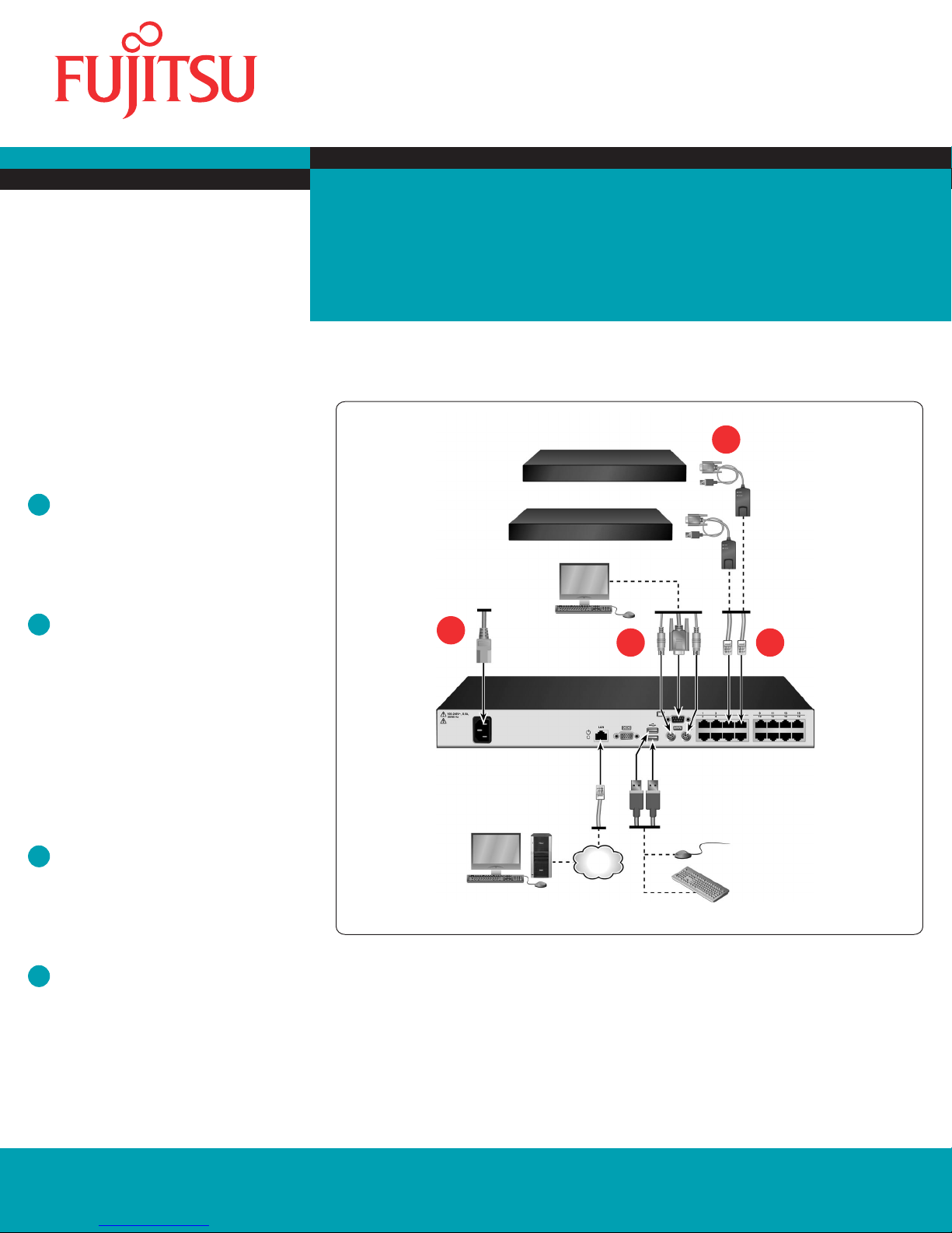
Connecting local peripherals
Locate your local peripherals. Plug your VGA, SVGA,
SGA or SXGA monitor or USB keyboard and mouse
cables into the corresponding local connection
ports.
2
Connecting a server to the switch
Choose a server port on the rear panel of the
switch. Plug one end of a CAT 5 cable, IQ module or
SMB Adapter module into a numbered port. If you
are using CAT 5 cable, plug the other end into the
RJ-45 connector of an IQ module.
Quick Installation Guide
s3-0801/1601 KVM Switch
s3-0810/1601 switch conguration
4
1 2
3
NOTE: The s3-0801/1601 switches support SMB
Adapter USB-VGA modules, as well as KVM
series2-Adapter modules.
3
Completing the connection
Plug your module into the appropriate ports on the
back of the server. Repeat this procedure for all
servers that will be connected to the switch.
4
Turning on targets and the switch
Locate the power cord that came with the switch
and plug the appropriate end into the power socket
on the rear panel of the switch. Plug the other end
into an appropriate AC wall outlet and then turn on
each target server.
Fujitsu Technology Solutions GmbH, User Documentation, 33106 Paderborn, Germany l Email - manuals@ts.fujitsu.com l Online - http://ts.fujitsu.com/support
All hardware and software names used are trademarks of their respective manufacturers. 590-1036-640A
Ethernet
s3-1601
switch shown
Page 2
Installation
3
Die folgenden Anweisungen leisten
Hilfestellung bei der Installation und
Verwendung Ihres 3-0801/1601-Switches.
Nähere Informationen sind in Ihrer
Installations- und Bedienungsanleitung
enthalten.
HINWEIS: Fahren Sie alle Zielserver herunter, die
an das KVM-Switching-System angeschlossen
werden sollen. Fahren Sie die Zielserver und den
KVM-Switch erst bei Schritt 4 wieder hoch.
1
Lokale Peripheriegeräte anschließen
Legen Sie Ihre lokalen Peripheriegeräte bereit.
Schließen Sie die VGA-, SVGA-, SGA- oder SXGA-
Monitor- oder USB-Tastatur- und Mauskabel an die
entsprechenden lokalen Anschlussports an.
2
Einen Server an den Switch anschließen
Wählen Sie einen Serverport auf der Geräterückseite
des Switches aus. Schließen Sie ein Ende eines
CAT 5-Kabels, IQ- oder SMB-Adaptermoduls
an einen nummerierten Port an. Wenn Sie ein
CAT 5-Kabel verwenden, verbinden Sie das andere
Ende mit dem RJ-45-Anschluss eines IQ-Moduls.
Schnellinstallationsanleitung
s3-0801/1601 KVM-Switch
s3-0801/1601 KVM-Switchkonguration
4
1 2
3
HINWEIS: Die s3-0801/1601 Switches unterstützen
SMB-Adaptermodule USB-VGA sowie KVM
series2-Adaptermodule.
3
Fertigstellen der Verbindung
Schließen Sie das Modul an die entsprechenden
Ports auf der Serverrückseite an. Wiederholen
Sie dieses Verfahren für alle Server, die an den
Switch angeschlossen werden sollen.
4
Zielgeräte und Switch einschalten
Schließen Sie das entsprechende Ende des
im Lieferumfang des Switches enthaltenen
Stromkabels an den Stromanschluss auf der
Rückseite des Switches an. Schließen Sie das
andere Ende an einer geeigneten Netzsteckdose
an und schalten Sie die Zielserver ein.
Fujitsu Technologie-Lösungen GmbH, User Documentation, 33106 Paderborn, Deutschland l Email - manuals@ts.fujitsu.com l Online - http://ts.fujitsu.com/support
Fujitsu
Technologie-Lösungen
Alle verwendeten Hardware- und Softwarebezeichnungen sind Marken der entsprechenden Hersteller. 590-1036-640A
Alle verwendeten Hardware- und Softwarenamen sind Marken ihrer entsprechenden Hersteller.
GmbH, User Documentation, 33094 Paderborn, Deutschland • Email - manuals@ts.fujitsu.com • Online - http://ts.fujitsu.com/support
Ethernet
s3-1601-
Switch abgebildet
Page 3

installation
3
Ces instructions vont vous guider lors de
l’installation et de l'utilisation de votre
commutateur KVM s3-0801/1601.
Pour tout renseignement supplémentaire,
veuillez consulter votre guide
d’installation et d’utilisation.
NOTA : Mettez hors tension tous les serveurs
destinés à être intégrés à la solution de commutation
KVM. Ne mettez pas sous tension les équipements
cibles et le commutateur KVM avant l'étape 4.
1
Connexion des périphériques locaux
Identiez les périphériques locaux. Branchez les
câbles de l'écran VGA, SVGA, SGA ou SXGA ou du
clavier et de la souris USB sur les voies locales
correspondantes.
2
Connexion d’un serveur au commutateur
Choisissez une voie de serveur sur le panneau
arrière du commutateur. Branchez l'une des
extrémités d'un câble CAT 5, d'un module IQ ou
d'un module adaptateur SMB sur l'une des voies
numérotées. Si vous utilisez un câble CAT 5,
branchez l’autre extrémité sur le connecteur RJ-45
d’un module IQ.
Guide d’installation rapide
Commutateur KVM s3-0801/1601
Conguration du commutateur s3-0801/1601
3
4
1 2
NOTA : Les commutateurs s3-0801/1601 prennent
en charge les modules USB-VGA adaptateur SMB,
ainsi que les modules adaptateur série 2 KVM.
3
Terminer la connexion
Branchez le module sur les voies correspondantes
à l'arrière du serveur. Répétez cette procédure pour
tous les serveurs à relier au commutateur.
4
Mise sous tension des équipements
Ethernet
commutateur s3-1601
illustré
cibles et du commutateur
Munissez-vous du cordon d’alimentation fourni
avec le commutateur et branchez l’extrémité
appropriée sur la prise située sur le panneau arrière
du commutateur. Branchez l'autre extrémité sur une
prise secteur appropriée et mettez sous tension
chacun des serveurs cibles.
Fujitsu Technology Solutions GmbH, Documentation utilisateur, 33106 Paderborn, Allemagne l E-mail : manuals@ts.fujitsu.com l Site Web : http://ts.fujitsu.com/support
Fujitsu
Technologie-Lösungen
Tous les noms de matériels et de logiciels utilisés sont des marques commerciales, propriété de leurs fabricants respectifs. 590-1036-640A
Alle verwendeten Hardware- und Softwarenamen sind Marken ihrer entsprechenden Hersteller.
GmbH, User Documentation, 33094 Paderborn, Deutschland • Email - manuals@ts.fujitsu.com • Online - http://ts.fujitsu.com/support
Page 4

instalación
3
Las instrucciones siguientes le ayudarán a
instalar y a utilizar el conmutador KVM
s3-0801/1601 fácilmente.
En caso de que necesite asistencia adicional,
consulte la guía de uso e instalación.
NOTA: Debe apagar todos los servidores que
formarán parte del sistema de conmutación KVM.
Espere hasta llegar al paso 4 para encender los
dispositivos de destino y el conmutador KVM.
1
Conexión de periféricos locales
Localice los periféricos locales. Enchufe los cables
del monitor VGA, SVGA, SGA o SXGA y del teclado
y del ratón USB en los puertos de conexión local
correspondientes.
2
Conexión de un servidor al conmutador
Seleccione un puerto de servidor en la parte
posterior del conmutador. Enchufe un extremo de un
cable CAT 5, un módulo IQ o un módulo adaptador
SMB en un puerto numerado. Si utiliza un cable
CAT 5, enchufe el otro extremo en el conector RJ-45
de un módulo IQ.
Guía de instalación rápida
Conmutador KVM s3-0801/1601
Conguración del conmutador s3-0810/1601
3
4
1 2
NOTA: Los conmutadores s3-0801/1601 son
compatibles con módulos adaptadores SMB
USB-VGA y con módulos adaptadores KVM series2.
3
Finalización de la conexión
Enchufe el módulo en los puertos adecuados
de la parte posterior del servidor. Repita este
procedimiento en todos los servidores que se vayan
a conectar al conmutador.
4
Encendido de los dispositivos de
Ethernet
Se muestra el conmutador
s3-1601
destino y del conmutador
Localice el cable de alimentación suministrado con
el conmutador y enchufe el extremo adecuado a la
toma de alimentación situada en el panel posterior
del conmutador. Enchufe el otro extremo a una
toma de pared de CA apropiada y, a continuación,
encienda cada uno de los dispositivos de destino.
Fujitsu Technology Solutions GmbH, User Documentation, 33106 Paderborn, Alemania l Correo electrónico - manuals@ts.fujitsu.com l Internet - http://ts.fujitsu.com/support
Fujitsu
Technologie-Lösungen
Todos los nombres de hardware y software mencionados son marcas registradas de sus respectivos fabricantes. 590-1036-640A
Alle verwendeten Hardware- und Softwarenamen sind Marken ihrer entsprechenden Hersteller.
GmbH, User Documentation, 33094 Paderborn, Deutschland • Email - manuals@ts.fujitsu.com • Online - http://ts.fujitsu.com/support
Page 5

Installazione
3
Istruzioni per l'installazione e l'utilizzo dello
switch KVM s3-0801/1601.
Per ulteriori informazioni, fare riferimento
alla guida all'installazione e manuale
dell'utente.
NOTA: spegnere tutti i server da collegare al
sistema di commutazione KVM. Accendere i
dispositivi di destinazione e lo switch KVM solo al
passaggio 4.
1
Collegamento delle periferiche locali
Individuare le periferiche locali in uso. Collegare
i cavi di monitor VGA, SVGA, SGA o SXGA o di
tastiera e mouse USB alle porte corrispondenti per
il collegamento locale.
2
Collegamento di un server allo switch
Scegliere una porta server sul pannello posteriore
dello switch. Collegare un'estremità di un cavo CAT 5,
di un modulo IQ o di un modulo adattatore SMB
in una delle porte numerate. Se si utilizza un cavo
CAT 5, inserire l'altra estremità nel connettore RJ-45
di un modulo IQ.
Guida all'installazione rapida
Switch KVM s3-0801/1601
Congurazione dello switch KVM s3-0801/1601
4
1 2
3
NOTA: gli switch s3-0801/1601 supportano moduli
adattatori SMB USB-VGA e moduli KVM
series2-Adapter.
3
Completamento del collegamento
Collegare il modulo alle porte corrispondenti sul
pannello posteriore del server. Ripetere l'operazione
per tutti i server da collegare allo switch.
4
Accensione dei dispositivi di
Ethernet
Switch
s3-1601
destinazione e dello switch
Individuare il cavo di alimentazione in dotazione
con lo switch e collegare l'apposita estremità alla
presa di alimentazione sul pannello posteriore dello
switch. Collegare l'altra estremità in una presa di
rete c.a. appropriata, quindi accendere tutti i server
di destinazione.
Fujitsu Technology Solutions GmbH, User Documentation, 33106 Paderborn, Germania l E-mail: manuals@ts.fujitsu.com l Sito Web: http://ts.fujitsu.com/support
Fujitsu
Technologie-Lösungen
Tutti i nomi dei prodotti hardware e software citati sono marchi dei rispettivi produttori. 590-1036-640A
Alle verwendeten Hardware- und Softwarenamen sind Marken ihrer entsprechenden Hersteller.
GmbH, User Documentation, 33094 Paderborn, Deutschland • Email - manuals@ts.fujitsu.com • Online - http://ts.fujitsu.com/support
Page 6

インストール
3
以下はs3-0801/1601 KVMスイッチのインス
トール/使用手順です。
詳細情報については、「インストーラ/
ユーザー・ガイド」を参照してくだ
さい。
注:KVM スイッチ・システム内の すべての
サーバーの電源を切ります。ターゲット・デ
バイスとKVMスイッチの電源は手順4まで入
れないでください。
1
ローカルの周辺機器の接続
ロー カルの周辺機 器を用意しま す 。VGA、
SVGA、SGA、SXGAモニターまたはUSBキー
ボードおよびマウスの各ケーブルをそれぞれ
対応するローカル・ポートに差し込みます。
2
サーバーとスイッチの接続
スイッチの背面パネルにあるサーバー・ポート
を1つ選択します。CAT 5ケーブル、IQモジュー
ルまたはSMBアダプター・モジュールの一端を
番号付きのポートに差し込みます。CAT 5ケー
ブルを使用している場合は、もう一方の端をIQ
モジュール の R J-4 5 コ ネ クターに差 し 込 み
ます。
注:
s3-0801/1601スイッチは、SMBアダプター
(USB-VGA)モジュールばかりでなく、KVM
serie s2の アダプター・モジュー ルにも対応
しています。
クイック・インストレーション・ガイド
s3-0801/1601 KVMスイッチ
s3-0801/1601スイッチの構成
3
4
1 2
イーサ
ネット
s3-1601
スイッチ
3
接続の完了
モジュールをサーバー背面の適切なポートに
差し込みます。スイッチに接続するすべての
サーバーでこの作業を行ってください。
4
ターゲット・デバイスとスイッ
の背面にある電源ソケットに差し込みます。
コードのもう一方の端部をAC電源のコンセン
トに差し込み、各ターゲ ット・サーバーの
電源を入れます。
チの電源投入
スイッチに付属の電源コードがあることを確
認し、コードの該当する側の端部をスイッチ
Fujitsu Technology Solutions GmbH, User Documentation, 33106 Paderborn, Germany l 電子メール - manuals@ts.fujitsu.com l オンライン - http://ts.fujitsu.com/support
Fujitsu
Technologie-Lösungen
使用されているハードウェアおよびソフトウェアの名称はすべて、それぞれのメーカーの商標です。 590-1036-640A
Alle verwendeten Hardware- und Softwarenamen sind Marken ihrer entsprechenden Hersteller.
GmbH, User Documentation, 33094 Paderborn, Deutschland • Email - manuals@ts.fujitsu.com • Online - http://ts.fujitsu.com/support
 Loading...