

Page 1
Assembly Instructions SMARTCASE S500
__________________________________________________________________________________________________________________________________________________________
Page 1 of 23 www.fujitsu.com
Assembly Instructions
SMARTCASE S500 (D3544-Sx) S26361-F5000-J004
_________________________________________________________________________________________________________
Table of Contents
Step 1 Prepare the Chassis ............................................................................................................................................. 2
Step 2 Mount the Cooler ................................................................................................................................................. 4
Step 3 Insert Modules ..................................................................................................................................................... 6
Step 4 MB-Mounting in Chassis .................................................................................................................................... 11
Step 5 Optional Mounting ............................................................................................................................................ 14
Mounting WLAN-antennas (optional) ...................................................................................................................... 14
WLAN-aerial cable mounting (optional) ................................................................................................................... 14
Speaker mounting (optional) ................................................................................................................................... 14
Mounting USB Type C (optional)............................................................................................................................... 15
Mounting COM Cable (optional) ............................................................................................................................... 18
Step 6 Close the Chassis ............................................................................................................................................... 19
Step 7 Add Stands ......................................................................................................................................................... 22
Page 2
Assembly Instructions SMARTCASE S500
__________________________________________________________________________________________________________________________________________________________
Page 2 of 23 www.fujitsu.com
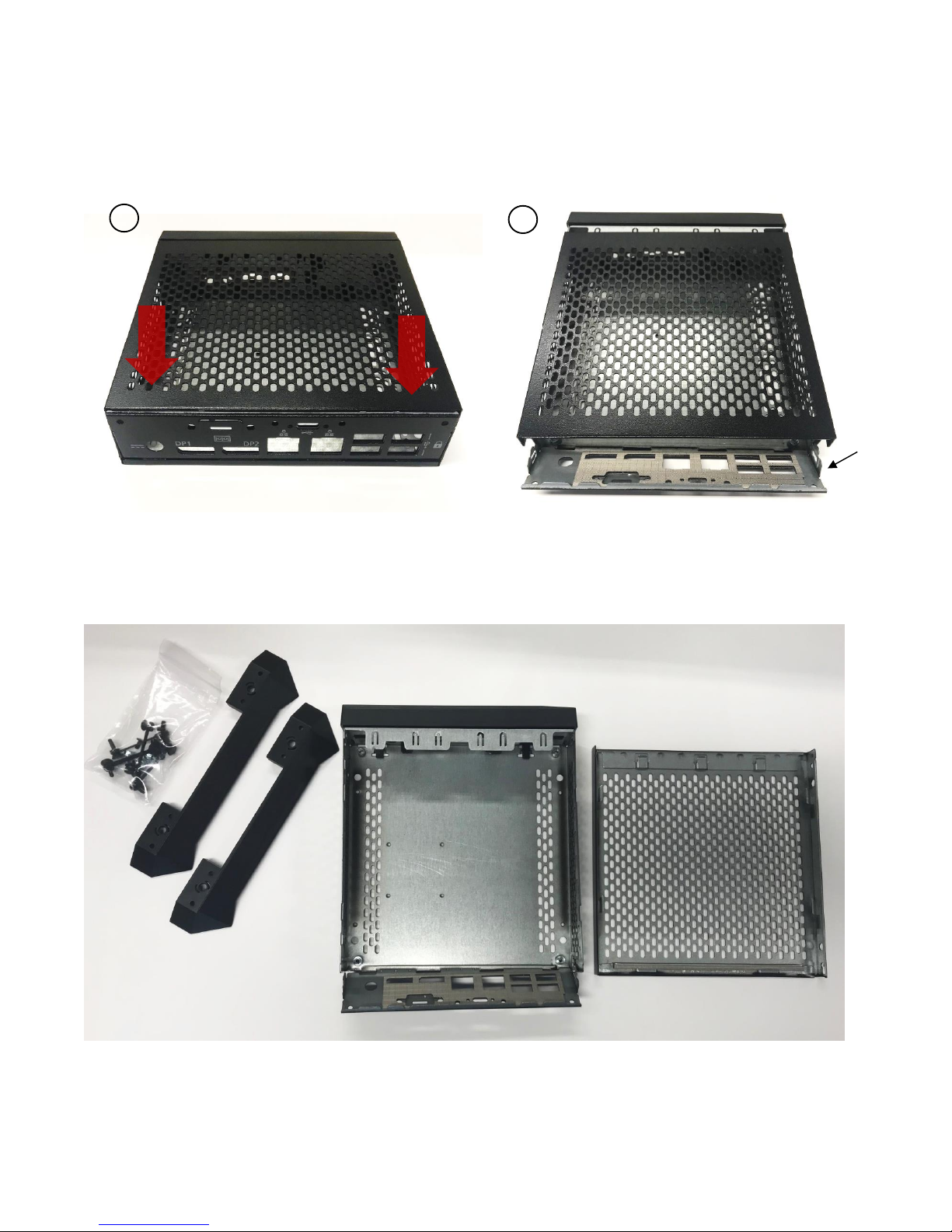
Step 1 Prepare the Chassis
Open the chassis with two hands by putting some pressure on your thumbs to push the cover reward.
Now you can take the top cover off. After opening the chassis unpack the contents.
1
2
rear i/o
Page 3
Assembly Instructions SMARTCASE S500
__________________________________________________________________________________________________________________________________________________________
Page 3 of 23 www.fujitsu.com
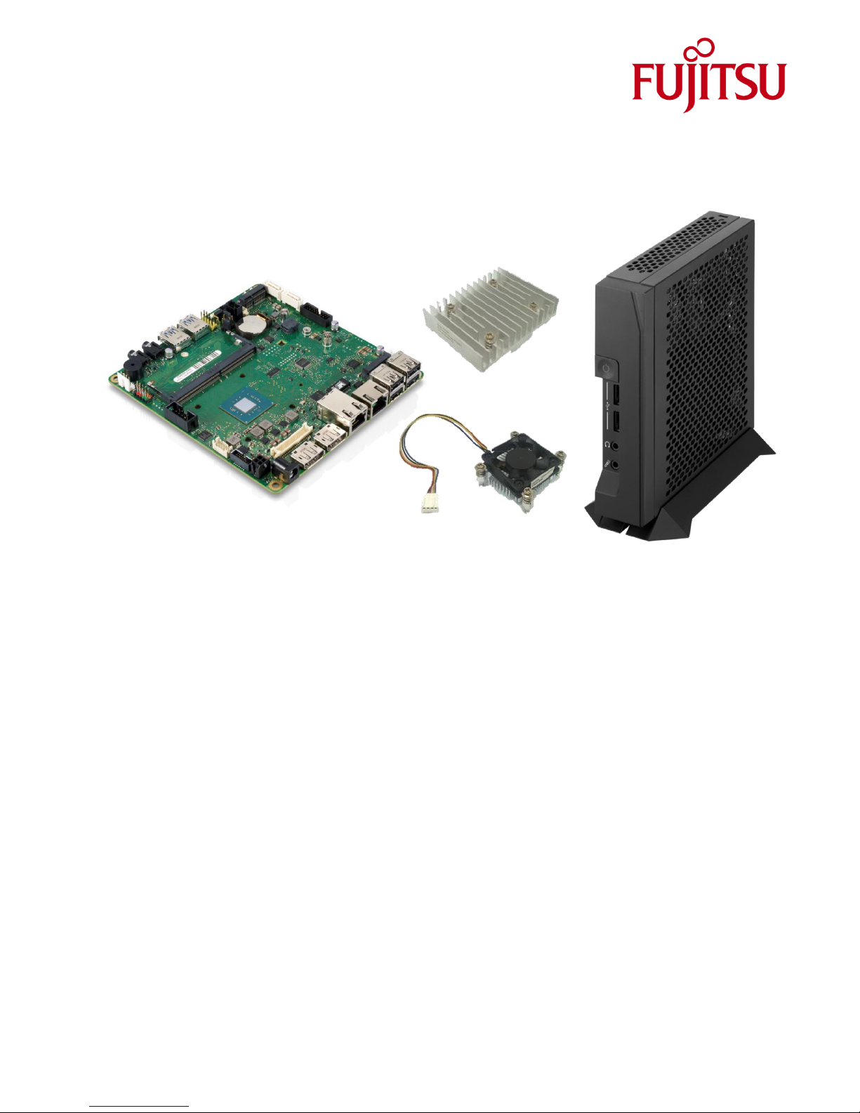
Overview of the content:
You can choose optional between the active cooler and the passive cooler. In the further instructions, we use the
passive cooler but you go the same way for the active cooler.
Mainboard
Passive Cooler
Active Cooler
Page 4
Assembly Instructions SMARTCASE S500
__________________________________________________________________________________________________________________________________________________________
Page 4 of 23 www.fujitsu.com
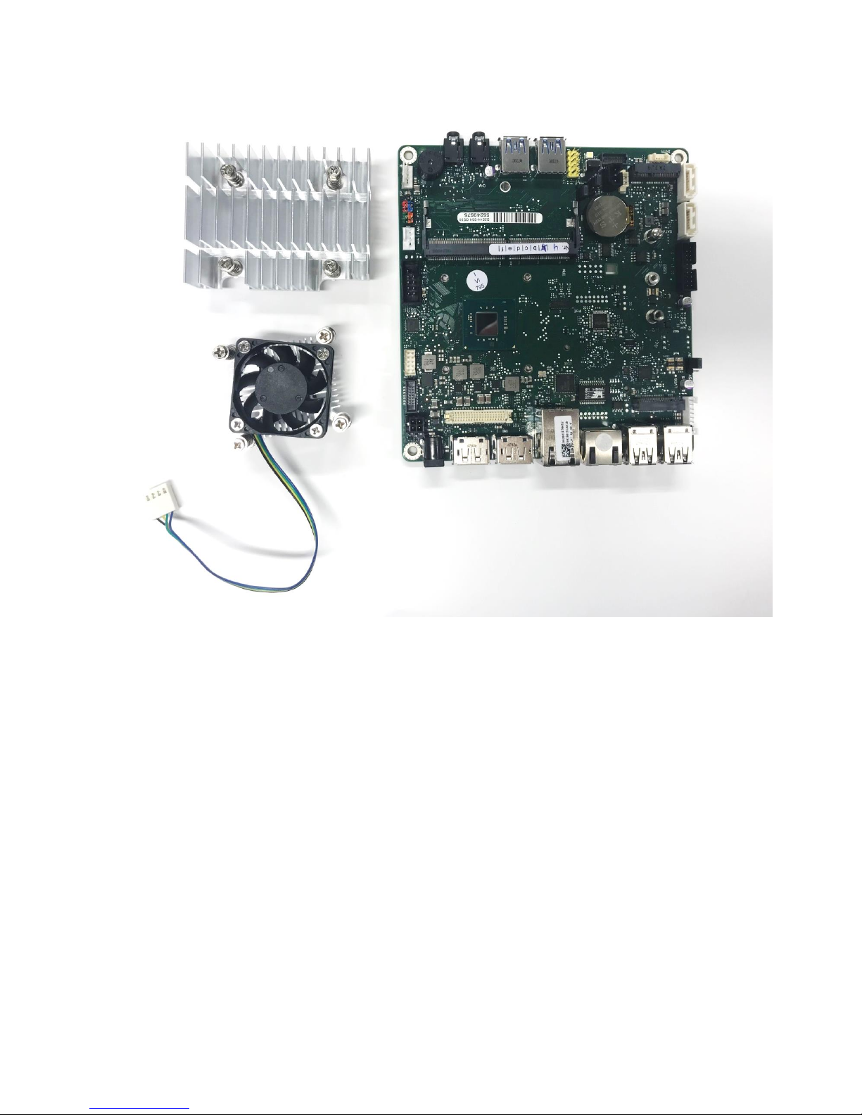
Step 2 Mount the Cooler
Before mounting the board into the chassis, it is necessary to add hardware to it first (CPU, Cooler, RAM, plus any
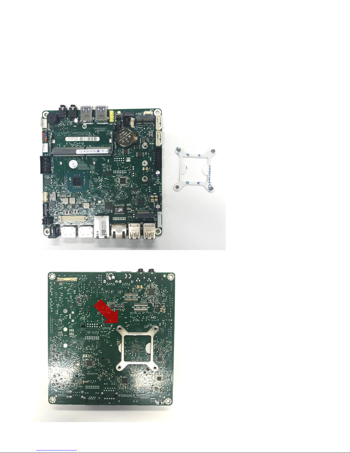
optional additional hardware). First start with the back plate, which is essential for the cooler.
Do not take the stripe off the back plate for sticking it onto the backside of the board. The sticker is necessary for
isolation and safety.
Place the back plate underneath the board.
The side with the indentation has to be positioned
directly under the screw. The end of the back
plate’s notches should be visible after the process.
Back plate
Page 5
Assembly Instructions SMARTCASE S500
__________________________________________________________________________________________________________________________________________________________
Page 5 of 23 www.fujitsu.com
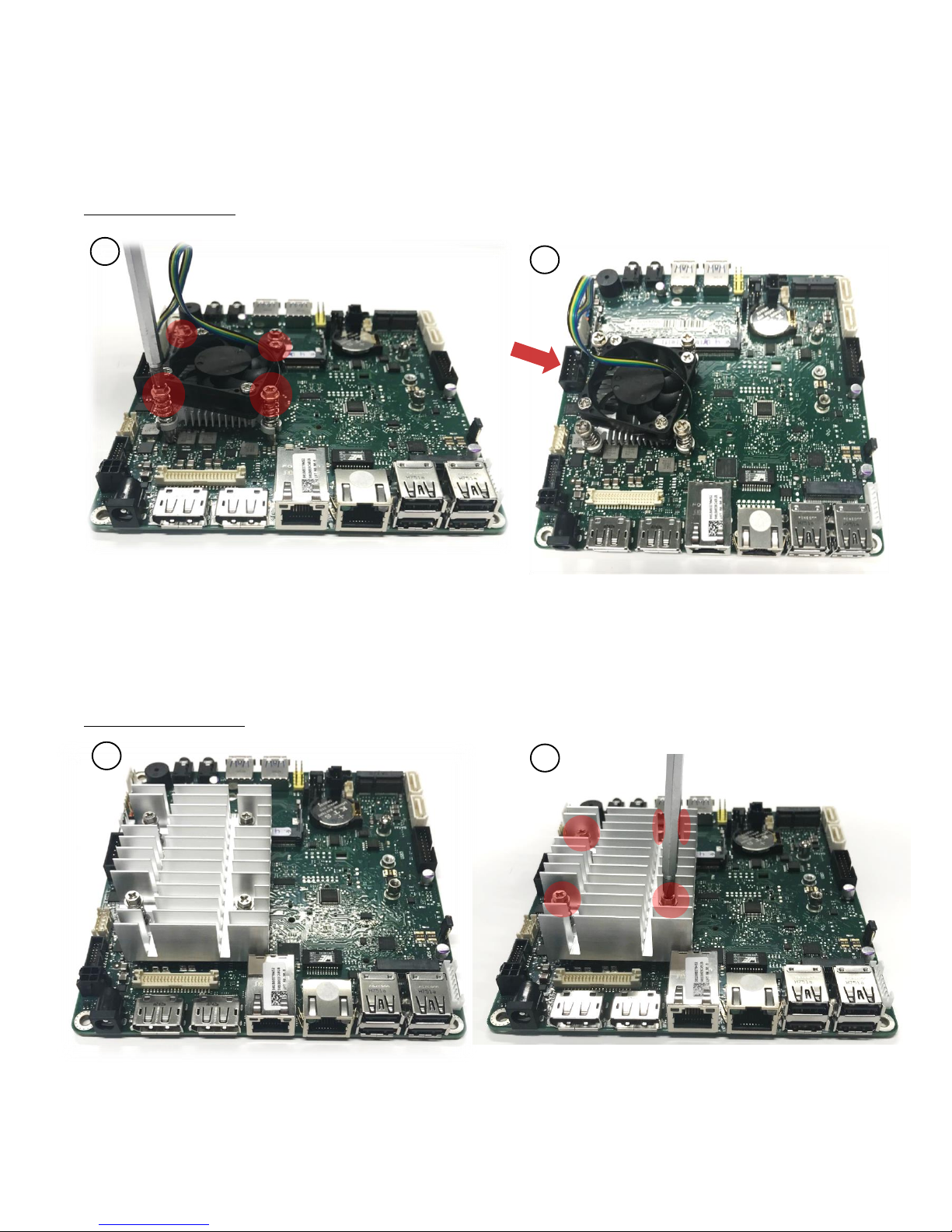
Next, mount the cooler on top of the CPU (1) and tighten the screws in the designated holes (2). Recommended
mounting screw torque: max. 0.8Nm. Be aware that the wire needs to be able to reach the red slot.
Option 1: Active Cooler
Put the cooler on top of the CPU and screw it onto the back plate through the board. Connect the cooler with the
board by the use of the cable connector (see arrow in Step 2).
Option 2: Passive Cooler
Then put the cooler on top of the CPU and screw it onto the back plate through the board. The thermal paste is
already applied.
1
2
1
2
Page 6
Assembly Instructions SMARTCASE S500
__________________________________________________________________________________________________________________________________________________________
Page 6 of 23 www.fujitsu.com
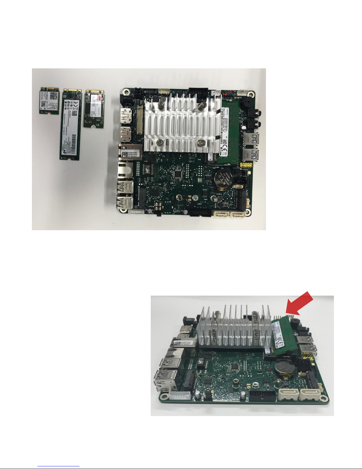
Step 3 Insert Modules
In the following picture, you can see the board with the three appropriated M.2 WLAN Modules or storage:
Next put the memory in tilted upwards and then push it down with a little pressure.
Attention: Do not touch the pin! Touch the memory at the outside edge. Do not stick a barcode on the memory!
The following procedure is necessary to make correct contact guarantee:
Insert memory at an angle and
pay attention to the notch!
Remove the memory again
completely from the DIMM slot!
Insert memory again
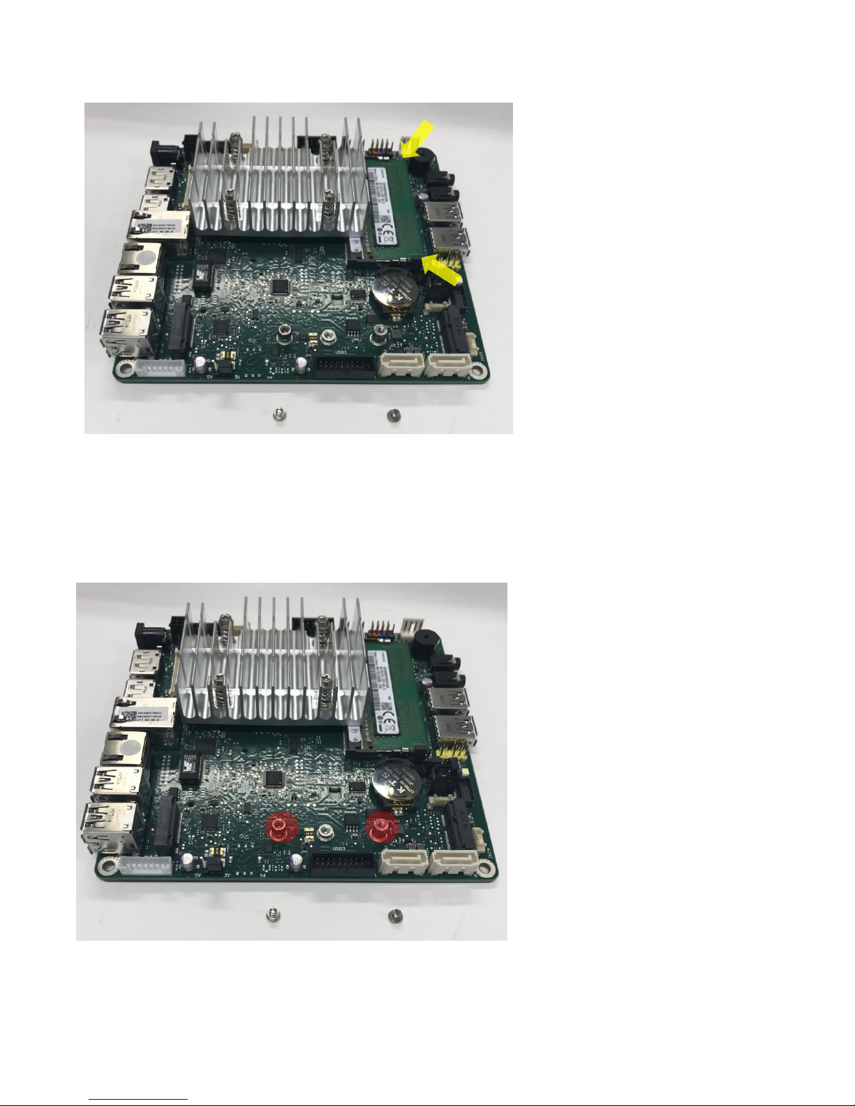
Press down on the memory until
it clicks into place
Do not press in the middle of the
memory, but press down on the
outer edges (yellow arrows on
the following picture)
Mainboard
M.2 2242
SSD/ Storage
M.2 SSD / Storage
2280
M.2 2230
WLAN
Memory
Page 7
Assembly Instructions SMARTCASE S500
__________________________________________________________________________________________________________________________________________________________
Page 7 of 23 www.fujitsu.com
WLAN - Module / M.2. Module mounting
First, you have to remove the screws.
Page 8

Assembly Instructions SMARTCASE S500
__________________________________________________________________________________________________________________________________________________________
Page 8 of 23 www.fujitsu.com
Option 1: M.2. WLAN 2230 and SSD / Storage
Insert WLAN card transversally into the slot (while paying attention to the coding / notch).
Both modules, as shown in the picture, always tackle on the outer edges.
Same procedure for the SSD / storage module (Option 2).
Pay attention
to the notch
In the next step you have to push it down a
little bit and tighten the screws in the
designated hole.
Now do the same step on the other side.
Page 9

Assembly Instructions SMARTCASE S500
__________________________________________________________________________________________________________________________________________________________
Page 9 of 23 www.fujitsu.com
If all screws are tighten up, the finished result should look like this:
Option 2: SSD / Storage Module
Now you have to put in the M.2. SSD /
Storage 2280 and M.2 2242.
Pay attention to the notch!
Page 10

Assembly Instructions SMARTCASE S500
__________________________________________________________________________________________________________________________________________________________
Page 10 of 23 www.fujitsu.com
In this case you only have to use one screw. So tighten up this screw in the next step.
The finished result should look like this:
Page 11

Assembly Instructions SMARTCASE S500
__________________________________________________________________________________________________________________________________________________________
Page 11 of 23 www.fujitsu.com
Step 4 MB-Mounting in Chassis
Start by putting all the connectors on the board through the designated holes in the chassis.
There are two different way to install the MB:
3
2
1. Swing in and push forward.
1
Page 12

Assembly Instructions SMARTCASE S500
__________________________________________________________________________________________________________________________________________________________
Page 12 of 23 www.fujitsu.com
Put this part back on the chassis.
Now push down the board so that the holes on the board fit onto the screw holes on the chassis.
2. Put MB in position and push
forward. The MB needs to be
carefully moved and not touching
the mounting panels (red circles).
1
2
Page 13

Assembly Instructions SMARTCASE S500
__________________________________________________________________________________________________________________________________________________________
Page 13 of 23 www.fujitsu.com
In the next step, use the screws for the mounting holes on the edges (red marked).
It should look like this now:
Page 14

Assembly Instructions SMARTCASE S500
__________________________________________________________________________________________________________________________________________________________
Page 14 of 23 www.fujitsu.com
Step 5 Optional Mounting
Mounting WLAN-antennas (optional)
Please check the color-coding of the antennas. On the front side the bays of the antennas are firmly defined and
marked with black and gray.
Push the antenna cables completely through the
opening in the housing and pay attention to the
guide nose (red circle).
Carefully install the WLAN antennas. The metal plate
must not be bent.
WLAN-aerial cable mounting (optional)
Hang the black WLAN cable in the hooks (red circles) and then plug the black cable into the connection with the
black triangle and the gray cable next to it on the module (yellow circle).
Attention: correct mounting of the WLAN- cable to avoid later collision with the Typ- C- plug
Speaker mounting (optional)
Before assembling the front panel the speaker needs to be installed into the front panel first.
Page 15

Assembly Instructions SMARTCASE S500
__________________________________________________________________________________________________________________________________________________________
Page 15 of 23 www.fujitsu.com
Mounting USB Type C (optional)
First, put the blue end in the belonging connector on the mainboard and push it down with some pressure.
Page 16

Assembly Instructions SMARTCASE S500
__________________________________________________________________________________________________________________________________________________________
Page 16 of 23 www.fujitsu.com
In the second step, you place the front part at an angle back on the chassis and push it (red arrow).
Page 17

Assembly Instructions SMARTCASE S500
__________________________________________________________________________________________________________________________________________________________
Page 17 of 23 www.fujitsu.com
Now bend the USB Cable as seen in the picture below and keep it to the appropriated holes.
Afterwards you fix it by screwing the bolts in the designated holes.
Afterwards slide the cover on the top of the chassis and screw the holes as explained in Step 6.
Page 18

Assembly Instructions SMARTCASE S500
__________________________________________________________________________________________________________________________________________________________
Page 18 of 23 www.fujitsu.com
Mounting COM Cable (optional)
For this option have a look at the attached “Assembly instruction for COM Cable with a D3544”.
Page 19

Assembly Instructions SMARTCASE S500
__________________________________________________________________________________________________________________________________________________________
Page 19 of 23 www.fujitsu.com
Step 6 Close the Chassis
Slide the cover on top of the board and chassis pushing it forward. Use some pressure to close it all the way.
1
3
2
Page 20

Assembly Instructions SMARTCASE S500
__________________________________________________________________________________________________________________________________________________________
Page 20 of 23 www.fujitsu.com
The last step to close the chassis is to put the screws in the designated holes and tighten them up.
Page 21

Assembly Instructions SMARTCASE S500
__________________________________________________________________________________________________________________________________________________________
Page 21 of 23 www.fujitsu.com
Now your chassis is completely assembled.
Page 22

Assembly Instructions SMARTCASE S500
__________________________________________________________________________________________________________________________________________________________
Page 22 of 23 www.fujitsu.com
Step 7 Add Stands
For this step, you need two stands and four screws. There are two possible positions for adding the stand. You can
you add them either on the bottom of the chassis or on the side of the chassis.
Put the clips in the prepared holes of the stands.
Page 23

Assembly Instructions SMARTCASE S500
__________________________________________________________________________________________________________________________________________________________
Page 23 of 23 www.fujitsu.com
Contact
FUJITSU
Fujitsu Technology Solutions Gmbh
Address: Bürgermeister-Ulrich-Straße 100
86199 Augsburg, Germany
Phone:
+49 821 804 0
Fax : +49 821 804 3329
E-mail: oem-sales@ts.fujitsu.com
© 2018 Fujitsu Technology Solutions GmbH. Fujitsu, the Fujitsu logo are
trademarks or registered trademarks of Fujitsu Limited in Japan and other
countries. Other company, product and service names may be trademarks
or registered trademarks of their respective owners. Technical data subject
to modification and delivery subject to availability. Any liability that the
data and illustrations are complete, actual or correct is excluded.
Designations may be trademarks and/or copyrights of the respective
manufacturer, the use of which by third parties for their own purposes may
infringe the rights of such owner.
You can place the stand next to the prepared holes as you can see in the picture.
Do the same step for the other side.
Finally, your chassis is finished and now it is ready for use!
Front view Back view
 Loading...