

Page 1
PRIMERGY ECONEL 30
Introduction
Important notes
Preparing for use
Operation
Troubleshooting and tips
Operating manual
System expansions
Technical data
Index
November 2002 edition
Page 2

Microsoft, MS, MS-DOS, Windows, and Windows NT are registered trademarks of Microsoft
Corporation.
VESA and DPMS are trademarks of Video Electronics Standards Association.
PS/2 is a registered trademark of Internat i onal Business Machi nes, Inc.
Pentium is a regis tered trademark of Intel Corporation, USA.
Kensington Lock and M i croSaver are registered tradem arks of ACCO World Corporation.
All other trademarks referenced are trademarks or regi stered trademarks of t heir respective
owners, whose protect ed ri ght s are acknowledged.
Copyright Fujitsu Siemens Computers Gm bH 2002
All rights, including rights of translation, reproduction by printing, copying or similar methods,
in part or in whole, are reserved.
Offenders will be liable for damages.
All rights, including rights created by patent grant or regis tration of a utility model or design,
are reserved.
Delivery subject to availability. Right of technical modification reserved.
This manual was produced by
cognitas. Gesel l schaft für Technik -Dokumentation mbH
www.cognitas.de
Page 3
Contents
Your PRIMERGY ECONEL 30.......................................................................................................... 1
Features............................................................................................................................................ 2
Notational conventions ......................................................................................................................3
Target group......................................................................................................................................3
Important notes ...............................................................................................................................5
Safety................................................................................................................................................5
Energy saving, di sposal and recycling.......................................................................................5
CE marking................................................................................................................................5
FCC Class B Compliance Statement.........................................................................................6
Transporting the server......................................................................................................................6
Cleaning the server............................................................................................................................ 6
Preparing for use.............................................................................................................................7
Unpacking and checki ng the de livery................................................................................................. 7
Steps for initial setup.........................................................................................................................7
Setting up the server .........................................................................................................................8
Connect the monitor, mouse and keyboard .......................................................................................8
Connecting the monitor..............................................................................................................8
Connecting the mouse...............................................................................................................9
Connecting a keyboard.............................................................................................................. 9
Connecting the server to the mains voltage.....................................................................................10
Initial switch-on: Software will be installed.................................................................................. .....11
Switching on monitor and server..............................................................................................11
Installing the software...................................................................................................................... 13
Configuration with ServerStart.................................................................................................13
Installation procedure in ServerStart........................................................................................14
Guided installation of a single server .......................................................................................15
Replicated installation of several servers (Windows) ...............................................................17
Connecting external devices............................................................................................................18
Ports on the server..................................................................................................................19
Connecting external devices to the serial port..........................................................................20
Connecting external devices to the parallel port.......................................................................20
Connecting external devices to the USB port...........................................................................21
Operation .......................................................................................................................................23
Switching the server on ...........................................................................................................23
Switching the server off ...........................................................................................................23
Indicators on the server...................................................................................................................24
Keyboard.........................................................................................................................................25
Important keys and key combinations......................................................................................25
Working with floppy disks ................................................................................................................27
Settings in BIOS Setup....................................................................................................................28
Property and data protection............................................................................................................28
Anti-theft protection and lead-sealing.......................................................................................28
BIOS setup security functions..................................................................................................29
A26361-K831-Z102-1-7619
Page 4
Contents
Troubleshooting and tips............................................................................................................. 31
Installing new software.................................................................................................................... 31
Power-on indicator remains unlit after you have switched on your device.......................................31
The screen stays bl ank ................................................................................................................... 32
No mouse pointer displayed on the screen ..................................................................................... 33
The floppy disk cannot be read or written ........................................................................................ 33
Time and/or date is not correct........................................................................................................34
Error messages on the screen ........................................................................................................34
Restoring the hard disk contents..................................................................................................... 34
Tips ................................................................................................................................................ 34
System expansions....................................................................................................................... 35
Information about boards ........................................................................................................35
Opening the casing......................................................................................................................... 36
Closing the casing........................................................................................................................... 37
Installing and removing a board ...................................................................................................... 38
Installing a board..................................................................................................................... 38
Removing a board................................................................................................................... 40
Low-Profile boards.......................................................................................................................... 42
Mounting slot adapter.............................................................................................................. 42
Removing slot adapter ............................................................................................................ 42
Installing and removing drives................................................................................................. 43
Removing the front panel ........................................................................................................43
Attaching the front panel ......................................................................................................... 44
Installing an accessible drive...................................................................................................45
Removing an accessible drive................................................................................................. 47
Changing the floppy disk drive ................................................................................................ 50
Installing or removing the hard disk drive................................................................................ 53
Extensions to the system board...................................................................................................... 57
Removing the power supply....................................................................................................57
Upgrading main memory......................................................................................................... 57
Replacing processor................................................................................................................57
Replacing lithium battery......................................................................................................... 58
Swinging the power supply in.................................................................................................. 58
Technical data............................................................................................................................... 59
Index ..............................................................................................................................................61
A26361-K831-Z102-1-7619
Page 5
Your PRIMERGY ECONEL 30...
...is available with various configuration levels with different hardware and software. In addition, you
can install ac cessible drives (e. g. DVD drive), hard disk dri ves and other boards.
This operating manual tell s you how to put your serv er i nto operation and how to operate it in dail y
use. This descri ption applies for all configuration levels. Dependi ng on t he configuration level
chosen some of the hardware components described m ay not be available on your server. Please
observe the notes on y our operating system.
Your server has a number of security features to ensure that no unauthoriz ed persons can access
your data. The securit y functions in t he BIOS Setup al so allow you to protect your data by means of
passwords. In addit i on, you can also mechani cally lock y our server.
ServerStart allows you under some operating systems to easily and quickly ins t all the latest driv ers
and operating system extensions with a few mouse clicks.
Further information on thi s server is provided:
• in the "Safety and Ergonomics" manual
• in the "Warranty" manual
• in the operating manual for the monitor
• in the technical m anual for the system board
• in the "BIOS Setup" manual
• in your operating system documentation
• in the information files (e.g. *.TXT, *.DOC, *.WRI, *.HLP)
Some of the manuals l i sted can be found on the "ServerBooks" CD provided with your
i
Keep this operating manual t ogether with your device. If you pass on the dev i ce to third parties, you
should include this m anual .
server. These manuals can be read and printed with Acrobat Reader, al so contained on
the CD.
A26361-K831-Z102-1-7619 1
Page 6
Your PRIMERGY ECONEL 30... Features
Features
PRIMERGY
ECONEL 30
Mechanical access protection
Device for "Kens i ngton Lock"
Eye for padlock or for sealing
BIOS-based access protection
System passwords
Activati ng and deactivating interf aces, including USB
Boot and write protect i on for floppy disk and hard disk drives
Virus protection i n the BIOS
Write protection for flash EPROM
Casing access m oni toring
System loc k, including support for hard disk password
X
X
X
X
X
X
X
X
X
Software access protection
LAN alarm with heartbeat f unction
Virus protection
F-Secure virus scanner
Administration functions
Desktop management: l ocal administrati on wi th ServerView
Desktop management: rem ote administration wi t h Rem oteView
Power supply with monitor output
Power supply with s wi tched monitor output
System Monitoring
Temperature monitoring
Cover monitoring
System st atus display
X
X
X
X
-
X
X
X
X
X
2 A26361-K831-Z102-1-7619
Page 7
Notational conventions Your PRIMERGY ECONEL 30...
Notational conventions
The meanings of the sy m bol s and fonts used in thi s manual are as follows:
CAUTION!
!
i
Ê Text which follows this symbol describes activ i ties that must be
indicates inform ation which is import ant for your health or for
preventing physic al dam age.
indicates import ant information which i s required to use the system
properly.
performed in the order shown.
Italics
"Quotation marks "
indicates commands or menu items
indicate names of chapters and terms that are being emphasized.
Target group
This operating manual is intended for thos e res ponsible for installing the hardware and ensuring that
the system runs smoothly. The operating manual contains all the information required for installing
your PRIMERGY ECONEL 30.
To understand the different expansion options, y ou need a knowledge of hardware and data
transmission, as well as basic knowledge of the operating system used.
A26361-K831-Z102-1-7619 3
Page 8

Page 9
Important notes
In this chapter you will find information regarding safety which it is essential to take note of when
working with your server.
Safety
CAUTION!
!
Pay attention t o t he i nformation provided in the "Safety and Ergonomics" manual and in
the following safety notes.
During installation and before operating the device, pl ease observe the inst ructions on
environmental condit i ons in the "Technical dat a" chapter as well as t he i nstructions in the
"Preparing for use" chapter.
You may only operate t he device, if the rated voltage for the devic e i s set to the local
mains voltage. Check the rated voltage set for this devi ce (see the "Preparing for us e"
chapter).
The main switch and the ON/O FF but ton do not disconnect t he server from the mains
voltage. To completely disconnect the mains voltage, rem ove the power plug from the
grounded mains outlet.
Remove the power plug before opening the uni t.
Replace the lithium battery on the system board in accordance wit h the instructions i n the
"Extensions to the system board" - "Replacing lithium battery" chapter.
Caution, components i n the system can get very hot.
Energy saving, disposal and recycling
Further information can be found on the CD provided with your c om puter.
CE marking
The shipped version of t hi s device complies with the requirements of the EEC directiv es
89/336/EEC "Electromagnetic compatibility" and 73/23/EEC "Low volt age directive".
A26361-K831-Z102-1-7619 5
Page 10
Important notes Transporting the server
FCC Class B Compliance Statement
The following statem ent applies to the products covered in this m anual , unless otherwise s pecified
herein. The statement for ot her products will appear in the accompanying documentation.
NOTE:
This equipment has been tested and found to comply wi t h the limits for a "Cl ass B" digital dev i ce,
pursuant to Part 15 of the FCC rules and meets all requirements of the Canadian Int erf erenceCausing Equipment Regulati ons. These limits are designed to provide reasonable protection against
harmful interference i n a residential install at i on. This equipment generates, uses and can radiate
radio frequency energy and, i f not installed and used i n strict accordance with the instructions, may
cause harmful interference to radio communications. However, there is no guarantee that
interference will not occur in a parti cular installation. If this equipment does cause harmful
interference to radio or tel evision reception, whi ch can be determined by turni ng t he equi pment off
and on, the user is encouraged to try to correct the interference by one or more of the following
measures:
Reorient or relocate the rec ei ving antenna.
Increase the separati on between equipment and the receiver.
Connect the equipment int o an outlet on a circuit di fferent from that t o whi ch the receiver is
connected.
Consult the dealer or an experienced radio/TV technici an for help.
Fujitsu Siemens Com puters GmbH is not respons i bl e for any radio or televisi on i nterference caused
by unauthorized modifi cations of this equi pm ent or the substitut i on or attachment of connec ting
cables and equipment other than those specified by Fujitsu Siemens Com puters GmbH. The
correction of int erf erence caused by such unauthorized modificat i on, substitution or attachment will
be the responsibility of t he user.
The use of shielded I/O cables is required when connecting this equipment t o any and all optional
peripheral or host devices. Failure to do so may violate FCC rules.
Transporting the server
CAUTION!
!
Transport all parts s eparately in their original pac kaging or in a packaging which protects
them from knocks and jolts, to the new site. Do not unpack them until all transportation
maneuvers are complet ed.
Cleaning the server
CAUTION!
!
Turn off all power and equipment s witches and pull the power plug out of the grounded
mains outlets.
Do not clean any interior parts yourself, l eave this job to a serv i ce technician.
Do not use any cleaning agent s that contain abrasi ves or may corrode plast i c.
Ensure that no liquid enters the system.
Wipe the casing with a dry cloth. If part i cularly dirty, use a cloth that has been m oi stened in mild
domestic detergent and then carefully wrung out. Use disinfectant wi pes to clean the key board and
the mouse.
6 A26361-K831-Z102-1-7619
Page 11
Preparing for use
CAUTION!
!
Unpacking and checking the delivery
It is recommended not to throw away the original packaging material! I t may be required for
reshipment at some l at er date.
Ê Unpack all the individual parts.
Ê Check the delivery for damage incurred during transportation.
Ê Check whether the delivery agrees with t he details in the deliv ery note.
Should you discov er that the delivery does not correspond to the deliv ery note, notify y our l ocal
sales outlet im m edi ately.
Please take note of the safety inform at i on in the "Important notes" chapter.
Steps for initial setup
Only a few steps are necessary to put your new server into operation f or t he first time:
− Select locat i on for server and set up serv er
− Connect the monitor, m ouse and keyboard
− Check the voltage at the mains outlet and connect the server to an el ectrical outlet. Switch
the server on
You will learn more about the individual steps in the following sections
External devices
i
If you have received other devices in addi t i on to your server (e.g. a printer or a modem),
do not connect these until after the initi al i nstallation. The fol l owi ng sections contai n a
description of how to connect these external devices: "Connect i ng external devices t o the
serial port" and "Connect i ng external devices t o the parallel port".
Drives and boards
If you have received drives or boards with your server, please do not i nstall them until
after first-t i m e setup. How to instal l dri ves and boards is desc ri bed i n t he "System
expansions" chapter.
A26361-K831-Z102-1-7619 7
Page 12
Preparing for use Setting up the server
Setting up the server
CAUTION!
!
When installing your server, giv e consideration to the recommendations and safety notes
in the "Safety and Ergonomics" booklet .
Set up the server only in its correct orientation. The points to observe are illustrated on the
following pages.
We recommend that you place your device on a surf ace with good anti-slip quali t i es. In
view of the multi tude of different fini shes and varnishes used on furniture, it is possible
that the rubber feet will mark the s urface they stand on.
Do not expose the serv er to extreme environmental conditions (see "Tec hni cal data"
chapter).
Provide at least 200 m m of clearance in front of, to the left of, and behind the ventilator
area of the server to ens ure adequat e ventilation. In order t o avoid overheating, do not
cover the ventil ation area of the monitor or the server.
Do not place several s e rvers one above the other.
Connect the monitor, mouse and keyboard
The ports for the monitor, mouse, and keyboard are on the rear of the server (see "Ports on the
server" chapter).
Connecting the monitor
Ê Follow the instructions contai ned i n the monitor manual to prepare the moni tor for operation
(e.g. connecting cables).
1
2
Ê Depending on the connector, plug the monitor's power cable into either the server (1) or the
mains outlet (2).
8 A26361-K831-Z102-1-7619
Page 13
Connect the monitor, mouse and keyboard Preparing for use
It is recommended to connect the monit or power cable to the server monitor socket. The
i
!
Ê Plug the data cable into the monitor port of the server.
monitor is then swi tched off automatically when you swit ch the server off.
The monitor is not switching off with the system if it is connected to a mains outlet . Switch
off the monitor with i ts own ON/OFF button.
CAUTION!
The monitor power cable may onl y be connected to the server monitor socket if the
monitor current cons umption is smaller than 1,5 A with 230 V or 3 A wit h 115 V. The
values for the monitor current consumpti on can be found in the technic al data on the
monitor or in the operating manual for the monitor.
Connecting the mouse
Depending on the equipment level selected, y our server will be supplied with a PS/2 mous e or a
USB mouse.
Connecting a PS/2 mouse
Ê Connect the PS/2 mouse to the PS /2 mouse port of the server.
Connecting USB mouse
Ê Connect the USB mouse to the USB port of the server.
If you do not attach a mouse at the PS/2 mouse port, you can disable the mouse
i
controller in the BIOS Setup in order t o free the IRQ12 for a different appl i cation.
Connecting a keyboard
Depending on the equipment level selected, y our server will be supplied with a standard keyboard or
a USB keyboard.
Connecting standard keyboard
Use the supplied key board cable only.
Ê Plug the other end of the keyboard cable (square pl ug) i nt o the socket on the unders i de of the
keyboard.
Ê Plug the round plug of the keyboard cable into t he keyboard port on the server.
Connecting USB keyboard
Use the supplied key board cable only.
Ê Plug the other end of the keyboard cable (square pl ug) i nt o the socket on the unders i de of the
keyboard.
Ê Insert the rectangular USB plug of t he keyboard cable into the USB port of the server.
A26361-K831-Z102-1-7619 9
Page 14

Preparing for use Connecting the server to the mains voltage
Connecting the server to the mains voltage
The server is equipped with a main switch and a wide range power suppl y. This means that m anual
voltage setti ng i s not necessary.
CAUTION!
!
Ê Ensure that the local mains v ol t age i s within the range of 100 V to 240 V .
The wide-range power supply automati cally sets i tself to the correct voltage within t he
range from 100 V to 240 V.
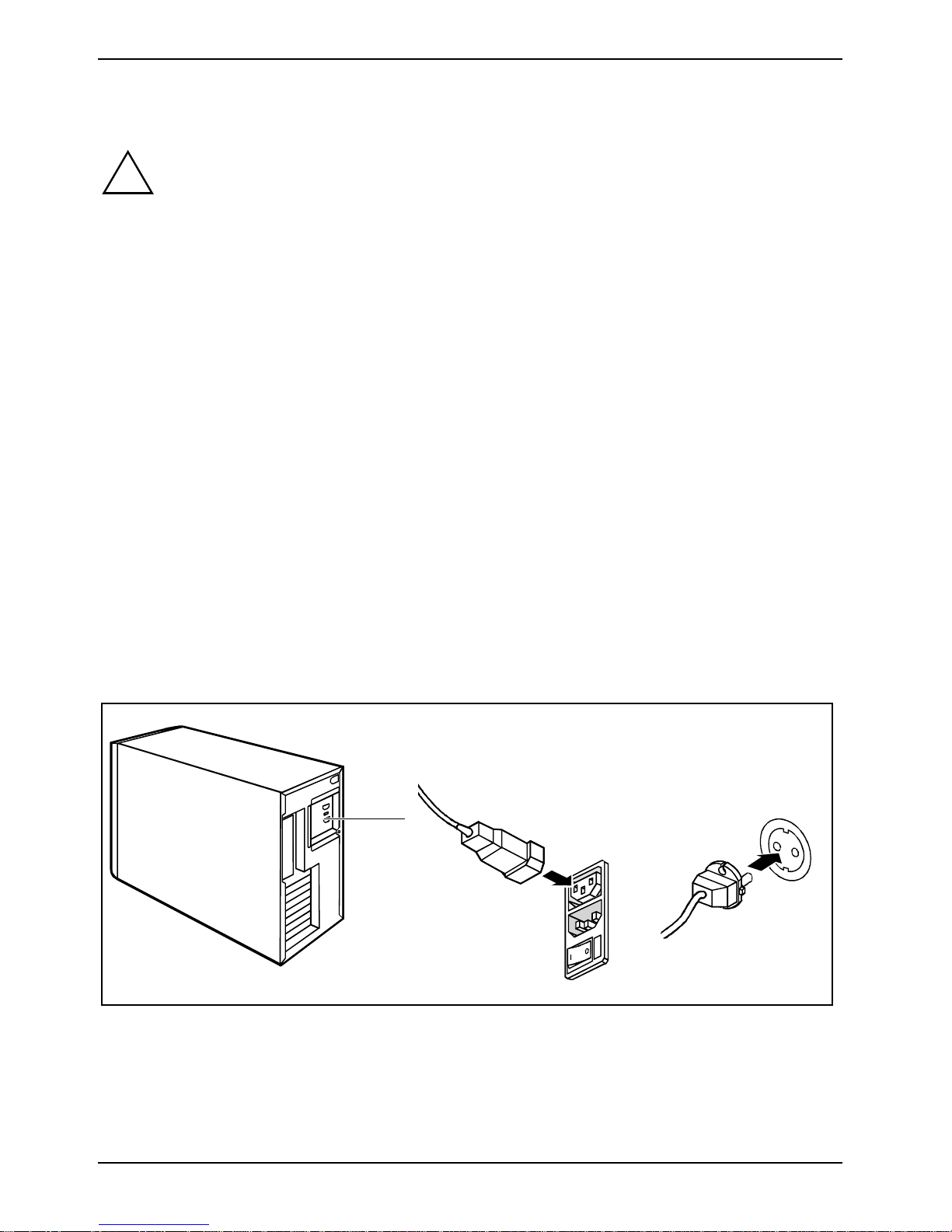
2
1
Ê Connect the power cable to the server (1).
Ê Plug the power plug into the grounded mains outlet (2).
10 A26361-K831-Z102-1-7619
Page 15
Initial switch-on: Software will be installed Preparing for use
Initial switch-on: Software will be installed
If the server is connected to a network , the network protocol is requi red as well as the user and
server details. Contact your network admi ni strator if you have any questions about thes e settings.
When you switch on your server for the first time, the supplied s oftware is install ed and configured.
You should plan some ti m e for this, as thi s process must not be interrupted.
CAUTION!
!
You may require the Windows l i cense number during installation. This number is located on a
sticker on your server.
Switching on monitor and server
Once the installat ion has been started the server must not be switched off!
During installation the server may only be rebooted when you are requested to do so!
Otherwise the installation will be not be performed correctly. If a fault occurs during the
installation, t he contents of the hard disk must be compl et el y restored.
Ê Switch the monitor on (see the operating m anual f or the monitor).
Ê Switch your server on. To do this, follow the instructions below.
Additionally to the ON/OFF button on the front a mai n switch at the rear of the server is
i
available.
A26361-K831-Z102-1-7619 11
Page 16
Preparing for use Initial switch-on: Software will be installed
I
1
0
2
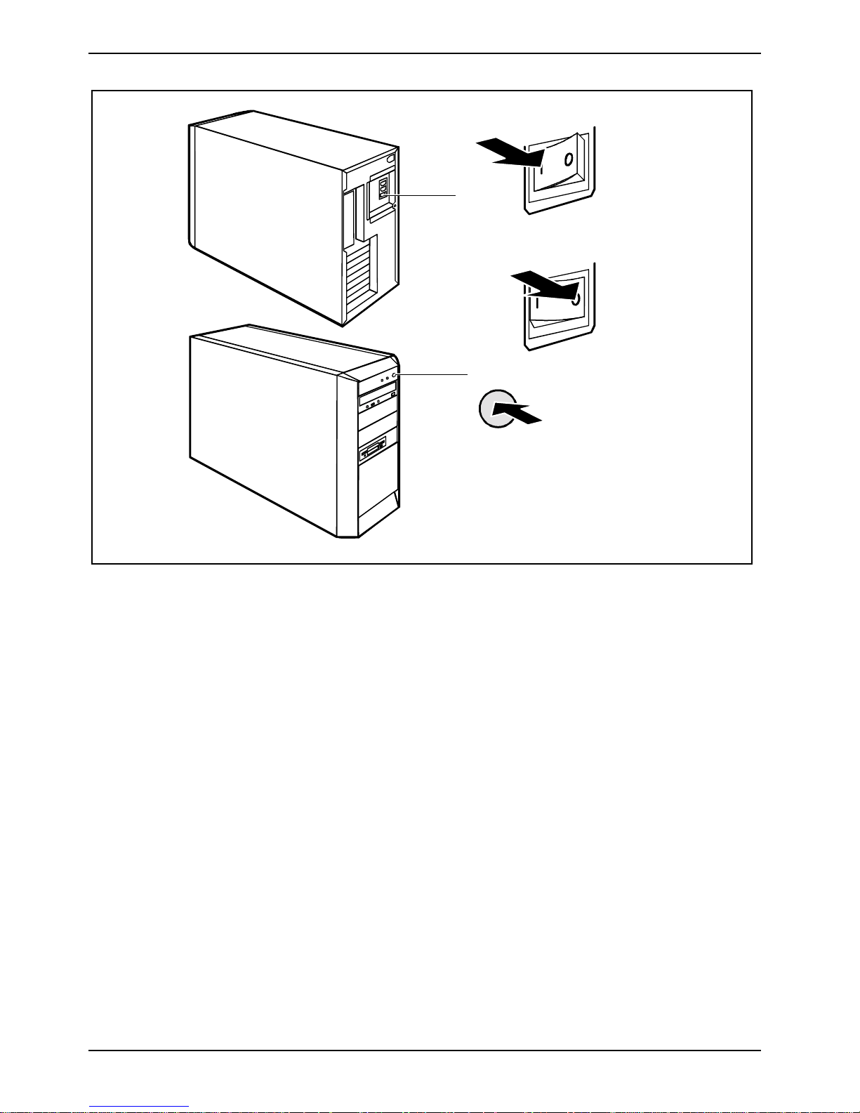
1 = Main switch
2 = ON/OFF button
Ê Switch the server on with the main switch at the rear of t he server (1).
Ê Press the ON/OFF button on the front of t he server (2).
The relevant indicators on the server light (s ee " Indicators on the server" chapter).
0 = Server is switched off
I = Server is ready-t o-operate
12 A26361-K831-Z102-1-7619
Page 17
Installing the software Preparing for use
Installing the software
Ê Insert the ServerStart CD and a possibly existing configurat i on floppy disk and rest art the server.
Follow the instructions in "Configuration wi th ServerStart" c hapter.
Ê During installation, follow the i nstructions on screen.
Consult the operating system manual if there is anything unclear about the requested input data.
Further information about t he system, drivers, utilities, updates, manuals etc., is contai ned
i
Configuration with ServerStart
ServerStart is a powerful tool for setting up your new PRIMERGY s erver ServerStart lets you quickly
and smoothly conf i gure and i nstall hardware, the operating system, and additional components.
The ServerStart advantage
• Automaticall y configure your serv er hardware and di sk arrays
on the "ServerStart " and "ServerBooks" CDs.
• Receive installation help for all leading s erver operating systems
• Create configuration fi l e s for the unattended inst al l ation of several PRIM ERGY servers with
identical hardware confi gurations
• Install drivers and additional software
Which software can be i nstalled depends on the hardware confi guration of your server.
i
This configuration i s automatically det ected.
A26361-K831-Z102-1-7619 13
Page 18
Preparing for use Installing the software
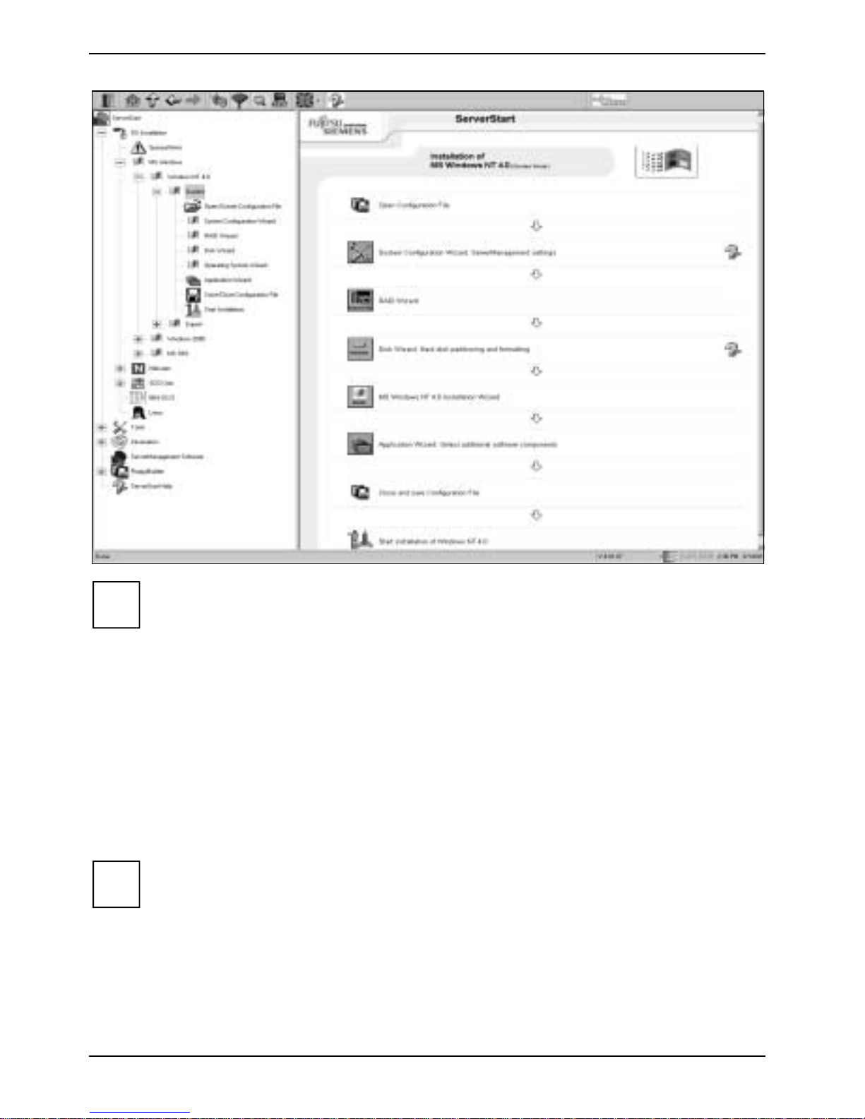
Using ServerStart
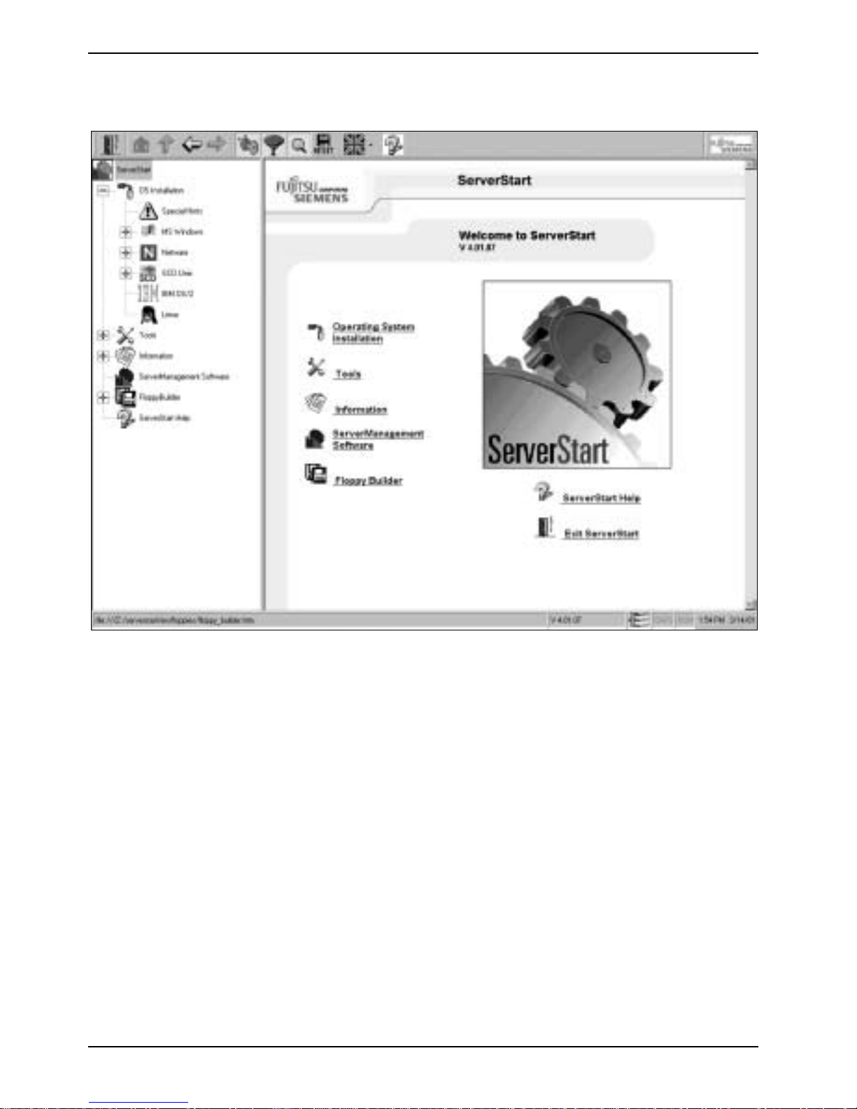
The ServerStart user interface is divided into two areas. Al l the menus for the application can be
quickly found in the Tree View area on the left. In the User Frame area on the right you can navigate
the underlined objects j ust as you would with an i nternal browser.
Installation procedure in ServerStart
With help of ServerStart you can carry out the first inst al l ation of your server and perform l ater
adjustments.
Preparation
To install your PRI M E RGY server and operating system, you need to boot the server from the
ServerStart-CD. In some circumstances you will need to adjust several settings to do this:
For CD-ROM drives on a IDE bus:
Ê Ensure that the corresponding IDE channel i s activated in the BIOS of the system board and
that the CD-ROM drive is the first boot dev i ce in the boot sequence (see index entry boot
sequence in the BIOS-Setup manual).
14 A26361-K831-Z102-1-7619
Page 19
Installing the software Preparing for use
Selecting the desired installation mode
To set up a single server:
It is recommended to configure ServerStart in Guided Mode on the target system. Compared to the
Expert Mode, this offers increased security by recognition and configuration of the hardware.
Continue with the "Installation in Guided Mode" chapter.
If you decide to install in Expert Mode, you will need to know the hard disk capacity and
i
To set up several servers with identical hardware configurations:
In this case, create a target confi guration file on a floppy disk either in the Preparation Mode or using
the example in the Guided Mode. Conti nue wi t h "Replicated instal l ation of several serv ers
(Windows)" chapter.
i
how to remove cards and c onf i gure hard di sks.
Only one boot system can be selected in the Preparation Mode and in the Guided Mode,
and only one RAID array can be s et as a boot device. If the capacity of the boot drive
cannot be determined, s el ect the "Automati c" option for an optimal partitioning.
Guided installation of a single server
Installation in Guided Mode
In Guided Mode, installation ass i stants configure your server hardware and disk array s and then
install the operati ng system and integrated applications. For t he new i nstallation, st andard settings
are loaded from a Default Configuration File. This configuration f i l e can be found on the ServerStart-
CD and may be edited by the admi n i strator.
Proceed as follows:
Ê Switch the server on and insert the ServerStart CD into t he dri ve.
Ê Switch the server off and on again. ServerStart will now be started from the CD-ROM on the
target system.
Ê After the boot process the ServerStart user interface appears. Select t he i nstallation mode and
follow the instal l ation process in the Use r F r ame.
Ê A hardware analysis of the target system is performed. Configuration data is gathered for the
installation.
Ê After the configuration definit i on has been completed, the installation phase is i ni tiated without
any additional restart. Data carriers wit h the operating system, Service packs, and additional
applications are then requi red to start the inst al l ation.
The rest of the inst al l ation process incl udi ng al l necessary restart s executes without any input from
the user.
Exception: Neces sary specifications that were not made in the configuration phas e will be
i
A26361-K831-Z102-1-7619 15
requested during the inst al l at i on.
Page 20
Preparing for use Installing the software
During the installat i on of Wi ndows NT/2000 and NetWare 5, ServerStart also automatically
i
integrates drivers for system components that are not contained in the operating system.
During the installat i on of other operating systems, ServerStart notifies the user of the
missing drivers. If necess ary the user can now make a driver installation floppy disk.
Alternative installation in Expert Mode
In contrast t o t he Disk and RAID Wizards in the Guided Mode, the Expert Mode lets you directly
configure the hardware using t he t ool s specifical l y from the manufacturer:
• Windows NT Disk Adm i ni strator, Global Flash ServiceParti tion Manager, DuplexData Partition
Manager
• Mylex GAM (Global Access Manager), S torage Manager
In connection wit h the configuration in the Expert Mode, the operating system installation can be
performed analogously to the Guided Mode.
To update BIOS, firm ware, and drivers with the Global Flash Tool, you will need a service
i
partition. You can set this up conveni ently using the Disk Wizard from ServerStart.
16 A26361-K831-Z102-1-7619
Page 21
Installing the software Preparing for use
Replicated installation of several servers (Windows)
Step 1: Making a boot drive in the Preparation Mode
In this operating mode wi th the help of the instal l ation assistant s, you can create adapted
configuration files for the unattended inst al l ation of your PRIMERGY server.
You can also set up i nstallation floppy di sks with all the detected configuration definitions
i
Proceed as follows:
The Preparation Mode starts if ServerStart was installed as an appli cation on an arbitrary Windows
server Because this computer is not necessarily the target system, no automatic hardware analysis
can take place. You will need to manually f ill in the necessary information (LA N t opology, computer
name, IP address).
Ê Fill in the required information in the corresponding menus.
!
after the configuration of the target system in Guided Mode and in Expert Mode.
CAUTION!
It is important to correctly specify the boot drive:
• Which SCSI device is the boot drive f or the SCSI controller (SCSI-ID)?
• How many drives are avai l abl e for a RAID array and which RAI D l evel (0/1/5) should
be used?
Other devices such as graphics cards or network hardware are automaticall y detected
i
Ê After the configuration has been completed, save the gathered i nformation in an arbitrary fi le
i
Ê In order to install a corresponding target system based on the gathered configuration data, you
and installed on the target system.
with the *.ini ext ension either on the hard disk or on a f l oppy disk. This f i l e can be reopened at
a time and modified from wi thin configuration user i nterface.
In this way you can store several configuration records for various target systems.
need to create via ServerStart a boot floppy di sk and copy the confi guration file to this f l oppy
disk under the filenam e SerStartBatch.ini.
A26361-K831-Z102-1-7619 17
Page 22
Preparing for use Connecting external devices
Step 2: Configuration of the target system in Replication M ode
Proceed as follows:
In the BIOS for the system board and SCSI adapter, define the boot sequence such that
i
Ê With the configuration floppy dis k in the drive, boot the target system from the ServerStart CD.
Device drivers needed to operat e the detected hardware components will be reported and pre
installed on the sel ected operating system.
!
i
the CD-ROM drive precedes t he floppy disk driv e (see the BIOS-Setup manual ).
ServerStart starts in Replication Mode and the installation runs automatical l y based on the
configuration fil e.
CAUTION!
To successfully install in Replication Mode, the configuration data must agree with the
hardware configuration on the target system.
Intervention in the installation process is only necessary to change carriers (operating
system, service packs, applications) and in t he event of an incorrect or i ncomplete
hardware recognition.
Installation is completed.
Connecting external devices
CAUTION!
!
Connecting cables
• Turn off all power and equipment s witches.
• Remove all power plugs from t he mains outlets.
• Plug all cables into the server and peripherals. Y ou must observe the inf ormation provided in
• Plug all data communication cables into the utility sockets.
• Plug all power cables into the grounded mains outlets.
Read the documentation on the external device before c onnecting it. The power plug mus t
be removed before connecti ng external devices, apart from devices wi t h US B interfaces.
Do not either connect or di sconnect cables duri ng storms.
Always take hold of the actual plug. Never unplug a cable by pulling the cable itself.
Connect and disconnect the cables in the order des cribed below.
the "Important notes" chapter.
18 A26361-K831-Z102-1-7619
Page 23
Connecting external devices Preparing for use
Disconnecting cables
• Turn off all power and equipment s witches.
• Remove all power plugs from t he mains outlets.
• Unplug all da ta co mmu ni catio n cab le s fro m th e u tility sockets.
• Disconnect all cables at the serv er and at the peripherals.
Devices with US B interfaces are hot-pluggable. This allows cables from these devic es to
i
be connected and disconnected with the system switched on.
Additional informat i on can be found in the "Connecting external devices t o the USB port"
section and in the doc um entation for the correspondi ng devices.
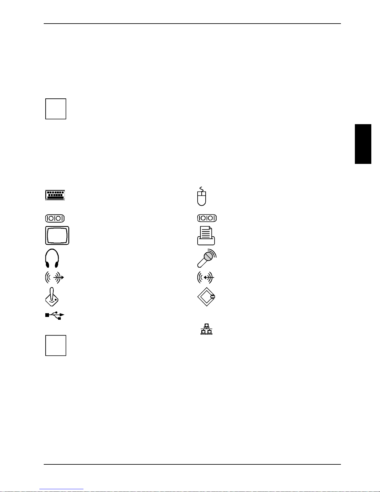
Ports on the server
The ports for external dev i ces are on the rear of the serv er. The ports available on your S erver
depend on the configuration level you have select ed. The standard ports are marked wi th the
symbols shown bel ow (or similar). Exac t details of the pos i t ion of the ports are supplied i n the
technical manuals for the boards.
Keyboard port, purple PS/2 mouse port, green
1
Serial port 1, teal or t urquoi se
Monitor port, blue Parallel port/Printer, burgundy
Headphones port, orange or light
green
Audio output (Line out), l i ght green Audio input (Line in), li ght bl ue
Game port, gold SCSI connection
USB - Universal S eri al Bus, black
Some of the devic es that you connect requi re special drivers (s ee the operating system
i
and device documentat i on).
LAN
2
Serial port 2, teal or t urquoi se
Microphone jack, pi nk or red
LAN connector
A26361-K831-Z102-1-7619 19
Page 24
Preparing for use Connecting external devices
Connecting external devices to the serial port
External devic es can be connected to the serial port (e.g. a modem).
Ê Connect the data cable to the external dev ice.
Ê Connect the data cable to the serial port .
For an exact description of how to connect external devices t o t he serial port, please refer to the
device documentat i on.
Settings of the serial port
i
If you need to change the settings of the serial port (e.g. address, interrupt), you can do
so in the BIOS Setup. The settings for the port are described in the technical m anual for
the system board or in the "BIOS Setup" manual.
Device drivers
The devices connec t ed to the serial port require driv ers. Your operating system already
includes many drivers. Nevertheless, if the driver y ou need i s not on the hard disk, please
install it f rom the data carrier supplied wit h the device or with the appli cation program.
Connecting external devices to the parallel port
External devic es can be connected to t he paral l el port (e.g. a printer).
Ê Connect the data cable to the external dev ice.
Ê Connect the data cable to the parallel port .
For an exact description of how to connect ex ternal devices to t he paral l el port, please see the
device documentat i on.
Settings of the parallel port
i
If you need to change the settings of the paral l el port (e.g. address, interrupt), you can do
so in the BIOS Setup. The settings for the port are described in the technical m anual for
the system board or in the "BIOS Setup" manual.
Device drivers
The devices connected to the parallel port require drivers. Your operating system already
includes many drivers. Nevertheless, if the driver y ou need i s not on the hard disk, please
install it f rom the data carrier supplied wit h the device or with the appli cation program.
20 A26361-K831-Z102-1-7619
Page 25
Connecting external devices Preparing for use
Connecting external devices to the USB port
You can connect a wide range of external devices to the USB port (e.g. printer, scanner, modem or
keyboard).
Devices with US B interfaces are hot-pluggable. This allows cables from those devic es to
i
Ê Connect the data cable to the external dev ice.
Ê Connect the data cable to the USB port .
i
be connected and disconnected with the system switched on.
Additional informat i on can be found in the documentat i on for the corresponding devic es.
Device drivers
The devices you c onnect to the USB port us ual l y require no driver of their own, as the
required software is already included in the operating system. However, if the device
requires its own sof tware, please install i t from the data carrier provided with the device.
A26361-K831-Z102-1-7619 21
Page 26

Page 27
Operation
Switching the server on
Ê If necessary, switc h the monitor on (see the operating m anual for the monitor).
Ê Switch the server on with the main switch at the rear of t he server.
Ê Press the ON/OFF button on the front of t he server.
The power-on indicator lights green (see "Indicators on t he server" chapter) and the s erver is
started.
Switching the server off
Ê Shut down the operating system properly.
Ê If the server operating system does not switch off automatically, use the ON/OFF button t o
switch off t he server when requested.
Switch the serv er off at the main switch.
CAUTION!
!
Ê If necessary, switc h the monitor off (see the operating manual for the monitor).
Placing a server (with soft power off function) in a ready-to-operate state by means of
software
With the soft power of f function the server automatically switches off (standby) or switches into the
energy-saving mode aft er the operating system is shut down. Requirements: Your system must
support switchi ng of f with software and this functionality must be enabled in BIOS Setup. The soft
power off software may al so need to be installed on Windows NT systems.
You can also switch your server into t he standby mode via ServerView- and/or RemoteView.
The main switch and the ON/O FF but ton do not disconnect t he server from the mains
voltage. To completely disconnect the mains voltage, rem ove the power plug from the
socket.
A26361-K831-Z102-1-7619 23
Page 28
Operation Indicators on the server
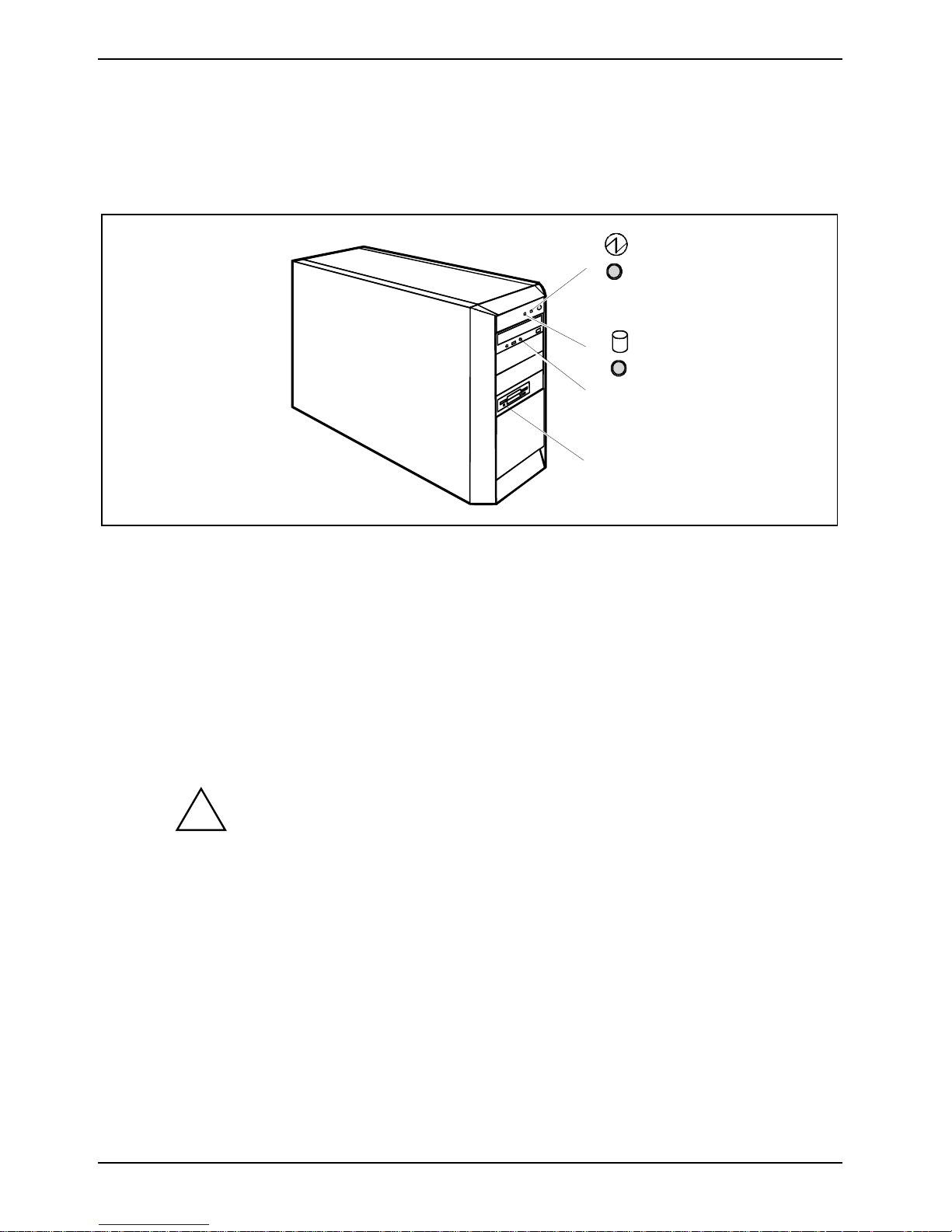
Indicators on the server
The indicators are on the f ront of the server. Which i ndi cators are available on your server depends
on the configuration lev el you have selected.
1
2
3
4
1 = Power-on indicator
2 = Hard disk indicator
3 = CD-ROM indicator
4 = Floppy disk indicator
1 - Power-on indicator
− The indicator lights green:
The server is on.
− The indicator lights orange:
The server is in energy-saving mode. After bei ng switched on, the serv er returns to the
state it was i n bef ore the energy-saving mode.
CAUTION!
!
− The indicator does not li ght up:
The server is swit ched off (main switch at 0 or disconnected f rom the power supply).
2 - Hard disk indicator
The indicator lights up when the hard disk drive of t he server is accessed.
In an energy-saving mode t he server must not be s witched off with the m ai n
switch or disc onnected from the mains supply, as this m ay result in data loss.
24 A26361-K831-Z102-1-7619
Page 29
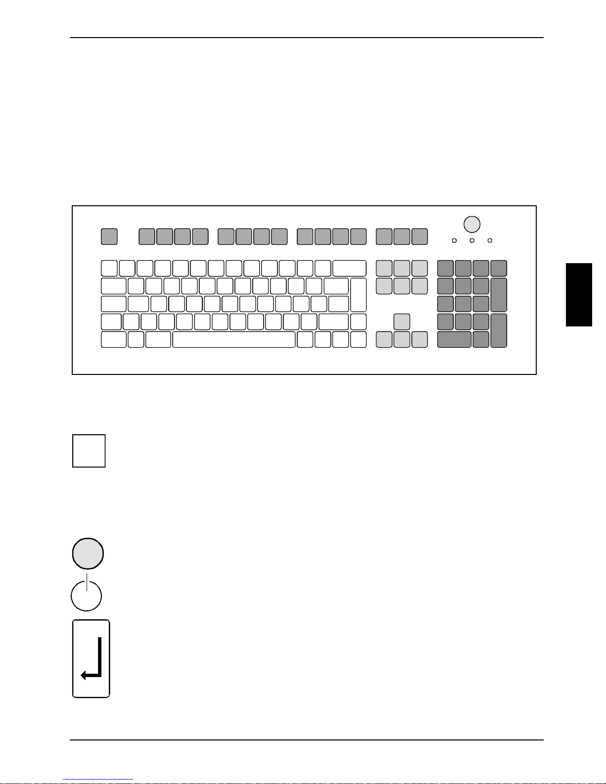
Keyboard Operation
3 - CD-ROM indicator
The indicator lights up when the CD-ROM drive of the serv er i s accessed. Y ou m ay only remove the
CD when the indicator is dark.
4 - Floppy disk indicator
The indicator lights up when the floppy disk drive of the server is accessed. You may only remove
the floppy disk when the indicator is unlit.
Keyboard
1
34
1 = Func t i on keys
2 = ON/O FF but ton (optional)
3 = Alphanumeric keypad
The illustrated keyboard is an ex ample and may differ from the model you use.
1 = Cursor keys
2 = Numeric keypad (calcul ator keypad)
i
Important keys and key combinations
2
5
The following descript i on of keys and key c ombinations refers to MS Windows. Details of other keys
and key combinations can be found in the document ation of the relevant application program.
ON/OFF button (optional)
Depending on the setting in t he BIOS Setup, the system can be switched on, off, or
on and off with this button. Some operating systems allow you to configure
additional functions of the ON/OFF button in the Control Panel.
On some keyboards the ON/ O FF but ton can only be used with ACP I. Otherwise the
key is inoperative. The system board must support this function.
Enter key
confirms the marked selection. The ent er key is also referred t o as the "Return" key.
A26361-K831-Z102-1-7619 25
Page 30
Operation Keyboard
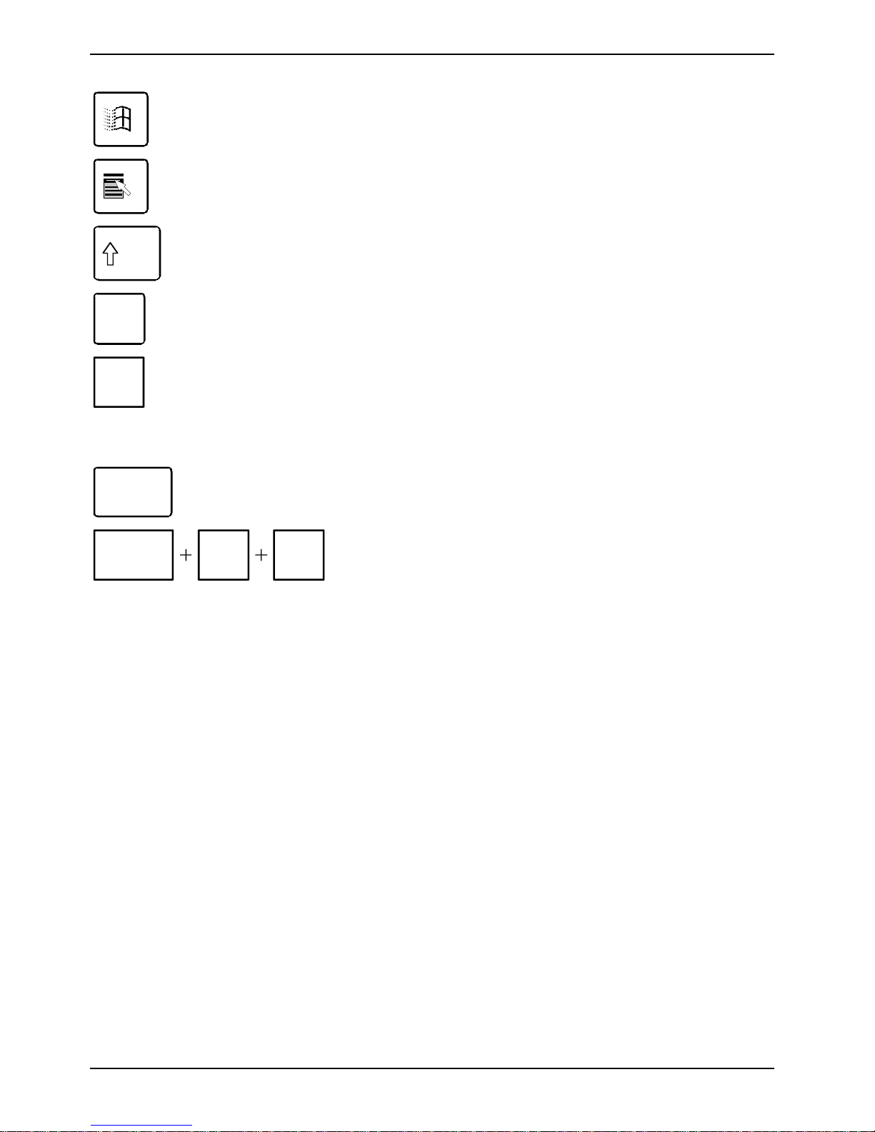
Start key
calls up the Windows Start menu.
Menu key
invokes the menu f or the marked item (Windows).
Shift key
enables upper-case lett ers and the upper key sym bol s to be used.
Alt Gr (e.g. German keyboard)
Alt Gr
produces a character s hown on the right-hand side of a key (e.g. the character @
on the key [Q]).
Num
Lock
Ctrl
Ctrl
Num Lock key
by pressing the Num Lock key you switch between the Numeric k eypad cursor
control functi ons and digit or comma func tions.
When the Num Lock indicator is lit the digit and comma keys are active.
When the Num Lock indic at or i s not lit the curs or control functions are active in the
Numeric keypad.
Ctrl key
starts key combination actions. The [Ctrl] key is als o called "Control" or "Control
key".
Warm boot
Alt Del
restarts your s erver. Press sim ul taneously the keys [Ctrl] + [Alt]
+ [Del]. Under some operating systems the Task Manager
appears first. Then y ou must press all t hree keys again to reboot.
26 A26361-K831-Z102-1-7619
Page 31
Working with floppy disks Operation
Working with floppy disks
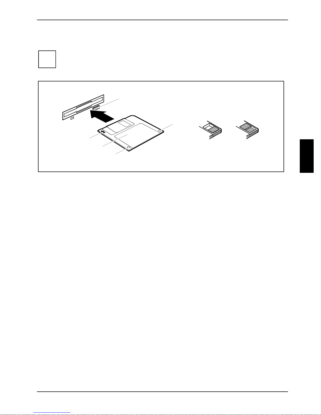
Follow the instruct ions supplied by the v endor of the floppy disks.
i
Never clean the floppy di sk drives with cleaning floppy disks. Any attempt would destroy
the read/write head in the dis k drive within 20 sec onds.
5
4
6
1
2
3
1 = Insertion direction
2 = Label area
3 = Write protection tab for a 1.44 Mbyte floppy dis k
4 = Identification of a 1. 44 MB floppy disk or wri te protect switch on a 120 MB floppy disk
5 = Eject button for ins ert ed floppy disks
6 = Floppy disk is write-prot ected
7 = Floppy disk is not writ e-protected
To insert a floppy disk:
7
Ê Push the floppy disk into the dri ve in the insertion direc tion (1) until it engages. The l abel
should be facing upward.
To remove a floppy disk:
Ê Push the eject button (5).
Protect the floppy disk against being overwritten or erased
Ê Slide the write-protect slider int o position (6). The hole is now v isible.
Deactivate write protection
Ê Slide the write-protect slider int o position (7). The hole is now c overed.
A26361-K831-Z102-1-7619 27
Page 32
Operation Settings in BIOS Setup
Settings in BIOS Setup
In BIOS Setup you can set the system functions and the hardware configuration of the server. When
the server is delivered, the default entri es are valid (see "BIOS Setup" manual and if nec essary
technical manual f or the system board). You may customi ze these settings to your requirements in
the BIOS Setup.
Property and data protection
Software functions and mechanical locking offer a broad range of funct ions for protecting y our
server and your personal data from unauthorized acces s. You can also com bine these functions .
Anti-theft protection and lead-sealing
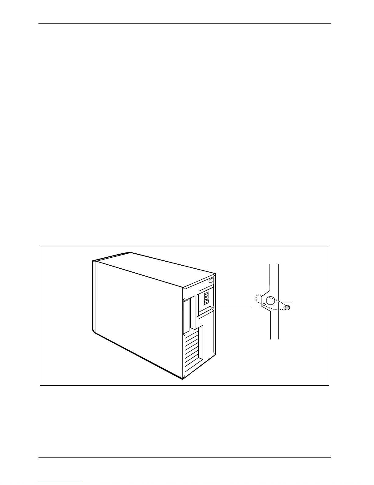
There are three ways to protec t your server from theft:
• with the Kensington Lock device (3) and with a K ensington MicroSaver
• with a chain (lead-seal)
• with a (pad)lock
To prevent unauthorized persons from opening the casing, the casing can be sealed.
Ê To do this, feed the sealing chain through t he l arge eye (1) and the small eye (2) and s eal t he
chain with the lead seal .
You can also attac h a padlock to the large eye (1) t o prevent unauthorized opening of t he casing.
You can also use thi s eye to anchor the cas i ng i f necessary.
a
1 = Large eye
2 = Small eye
3 = Device for "Kensingt on Lock"
28 A26361-K831-Z102-1-7619
Page 33
Property and data protection Operation
BIOS setup security functions
The Security menu in BIOS Setup offers you various options for prot ecting your personal data against
unauthorized access, e.g.:
• Preventing unauthorized BIOS Setup entry
• Preventing unauthorized system access
• Preventing unauthorized access to the s ettings of boards wit h t heir own BIOS
• Preventing system booting from the floppy di sk drive
• Activating virus warnings
• Preventing unauthorized wri ting of floppy disks
• Protecting BIOS from being overwritten
• Protecting the s erver from being switched on by an external device
You can also combine these functions.
You will find a detailed description of the Security menus and how to assign passwords in the
technical manual f or the system board or in the "BIOS Setup" manual.
A26361-K831-Z102-1-7619 29
Page 34

Page 35
Troubleshooting and tips
CAUTION!
!
Take note of the safety notes in the "Safety and Ergonomics" manual and in the
"Preparing for use" chapter, when you connect or disconnect cables.
If a fault occ urs, try to correc t it as described in the following places:
• in this chapter
• in the documentation of the connected devices
• in the help systems of the software used
• in the documentation of your operating system
If you fail to correct the problem, proceed as follows:
Ê Switch the server off.
Ê Make a note of the steps and the circumstances that l ed to the fault.
Ê Make a note of any error messages displ ayed.
Ê Note the ID number of your device. This number can be found on the type rati ng pl ate on the
back of the cas i ng.
Ê Contact your sales outlet or our customer service center.
Installing new software
When installing programs or drivers, import ant files may be overwritten and modified. To be able to
access the origi nal data in the event of any probl em s following install ation, you should back up your
hard disk prior to ins t al l ation.
Power-on indicator remains unlit after you have
switched on your device
This may be due to the fol l owi ng:
The mains voltage supply is faulty
Ê Check whether the power cable is plugged properly into the server and mains out l et.
Ê Switch your server on.
Internal power supply overloaded
Ê Pull the power plug of the server out of the m ains outlet.
Ê Wait for a moment.
Ê Plug the power plug into the grounded mains outlet agai n.
Ê Switch your server on.
A26361-K831-Z102-1-7619 31
Page 36
Troubleshooting and tips
The screen stays blank
If your screen remai ns blank this may be due to the following:
Monitor is switched off
Ê Switch your monitor on.
Power saving has been activated (screen is blank)
Ê Press any key on the keyboard.
or
Ê Deactivate the screen saver. Enter the appropriate password.
Brightness control is set to dark
Ê Adjust the brightness control . For detailed information, pl ease refer to the operating manual
supplied with your moni tor.
Power cable not connected
Ê Switch off the monitor and the server.
Ê Check that the monitor power cable is properl y connected to the moni tor and, depending on the
connector, to the server or to a grounded mains outl et.
Ê Check whether the power cable of the server is properly connected to t he server and to the
mains outlet.
Ê Switch on the monitor and the server.
Monitor cable not connected
Ê Switch off the monitor and the server.
Ê Check that the monitor cable is properl y connected to the server and monitor.
Ê Switch on the monitor and the server.
Wrong monitor has been set under Windows 2000
Ê Reboot the server.
Ê If the message Starting Windows appears, press funct i on key [F8].
The Windows 2000 Advanced Options Menu appears.
Ê Select Safe Mode or Safe Mode with Network.
Ê Set the correct values for the attached monitor as des cribed in the operating manual of the
monitor by selec t i ng Start - Settings - Control Panel - Display - Settings.
32 A26361-K831-Z102-1-7619
Page 37
Troubleshooting and tips
Wrong monitor has been set under Window XP
Ê Reboot the server.
Ê Press [F8] while the system is booting.
Either the Windows Advanced Start Options menu or the menu for select i ng the operating system
appears.
Ê If the menu for selecting the operati ng system appears, press [F8].
Ê Select Safe Mode or Safe Mode with Network.
Ê Set the correct values for the attached monitor as des cribed in the operating manual of the
monitor by selec t i ng Start - Settings - Control Panel - Display and then the Appearance, Themes,
Settings tabs.
The wrong RAM modules have been inserted
See the technical manual for the system board for information on whi ch memory modules can be
used.
No mouse pointer displayed on the screen
Ê Shut down the operating system properly.
Ê Switch the server off.
Ê Check that the mouse cable is properl y connected to the system unit.
If you use an adapter or ex t ension lead with the mouse cable, check the connections.
Ê Make sure that only one mouse is c onnected.
Ê Switch your server on.
The mouse controller mus t be enabled if you use a PS/2 mouse on the PS/2 mouse port
.
Ê Check in the BIOS Setup that the mouse control l er i s Enabled.
Ê Check that the mouse driver is properl y installed and is pres ent when the application program
is started. Det ai l ed i nformation can be found in the user guide for the mouse and applic ation
program.
The floppy disk cannot be read or wri tten
Ê Check that the write protection of the floppy disk or t he floppy disk driv e i s activated (refer t o
the "BIOS Set up" m anual and i f necessary to t he technical manual for t he system board).
Ê Check the entry for Floppy disk A in the Main menu of the BIOS Setup.
Ê Check that the floppy disk dri ve controller is enabled (al so refer to the technical manual for the
system board or to the "BIOS Setup" manual).
Ê Check that the cables of the fl oppy disk drive are properly connected (refer to "Changing t he
floppy disk drive" chapter).
A26361-K831-Z102-1-7619 33
Page 38
Troubleshooting and tips
Time and/or date is not correct
You can set the ti m e and date in the BIOS Setup or in the operating system.
Ê Set the time and date.
If the time and date are repeatedly wrong when you switc h on your server, the on-board
i
battery is fl at . Change the lithium batt ery as described in the "Extensions to t he system
board" - "Replacing lithi um battery" chapter.
Error messages on the screen
Error messages and thei r explanation are contained:
• in the technical m anual for the system board
• in the "BIOS Setup" manual
• in the documentation f or the programs used
Restoring the hard disk contents
Should you need to restore y our hard di sk, the instructions are provided on the c ase of the
"Recovery CD" (delivered with your system).
Tips
The server cannot be switched off with the ON/OFF button
Cause: The server has not been switched on with the ON/OFF but ton.
Ê Press the ON/OFF button again.
Cause: System crash
Ê Press and hold the ON/OFF button for at least four seconds until t he server switches off.
Out of system resources
If you have too many applications running at once, you may experienc e probl em s due to a lack of
system resources. In this case you should:
Ê close unnecessary applicati ons
or
Ê run the applications in a different order
Other manuals
Other manuals are contained on the "Drivers & Utilities" CD.
34 A26361-K831-Z102-1-7619
Page 39
System expansions
CAUTION!
!
This chapter describes all t he activities required to modify your server hardware (e.g. inst alling
boards or drives).
Read the supplied documentation before installing new drives and/or boards.
Refer to the technical manual for the system board before making any extensions to t he system
board.
It may be necessary to update the BIOS when carrying out a system expansion or
hardware upgrade. Additional inform ation is contained in t he " BIOS Setup" manual or
possibly in the technical manual for t he system board.
When installing components that bec ome very hot, make sure that the maximum
permissible tem perat ures of the individual c omponents are not exceeded.
The server must be switc hed of f when installing/removing the system expansions and
may not be in the energy-s aving mode.
Remove the power plug before opening the server.
Information about boards
Take care with the loc king mechanisms (catches and centering pi ns) when you are replacing boards
or components on boards.
To prevent damage to the board or the c om ponents and conductors on it, please take care when
you insert or remove boards. Make sure expansi on boards are inserted straight l y.
Never use sharp object s (screwdrivers) for l everage.
Boards with elect rostatic sensi t i ve devices (ESD) are i dentifiable by the
label shown.
When you handle boards fitt ed wi t h ESDs, you must , under all
circumstances, observe the fol lowing points:
• You must statically discharge yourself before worki ng wi th boards (e.g.
by touching a grounded object ).
• The equipment and tools you use must be free of st atic charges.
• Pull out the power plug before inserting or removing boards.
• Always hold boards with ESDs by their edges .
• Never touch pins or c onductors on boards fitt ed wi th ESDs.
A26361-K831-Z102-1-7619 35
Page 40
System expansions Opening the casing
Opening the casing
Ê Switch the server off. The server must not be in the energy-saving mode.
CAUTION!
!
Ê Remove any connected cables in the uni t that obstruct you.
Ê Place the device in a convenient working position.
Please take note of the safety inform at i on in the "Important notes" chapter.
Pull the power plug out of t he m ai ns outlet.
Only insert the power plug after you have closed the casing.
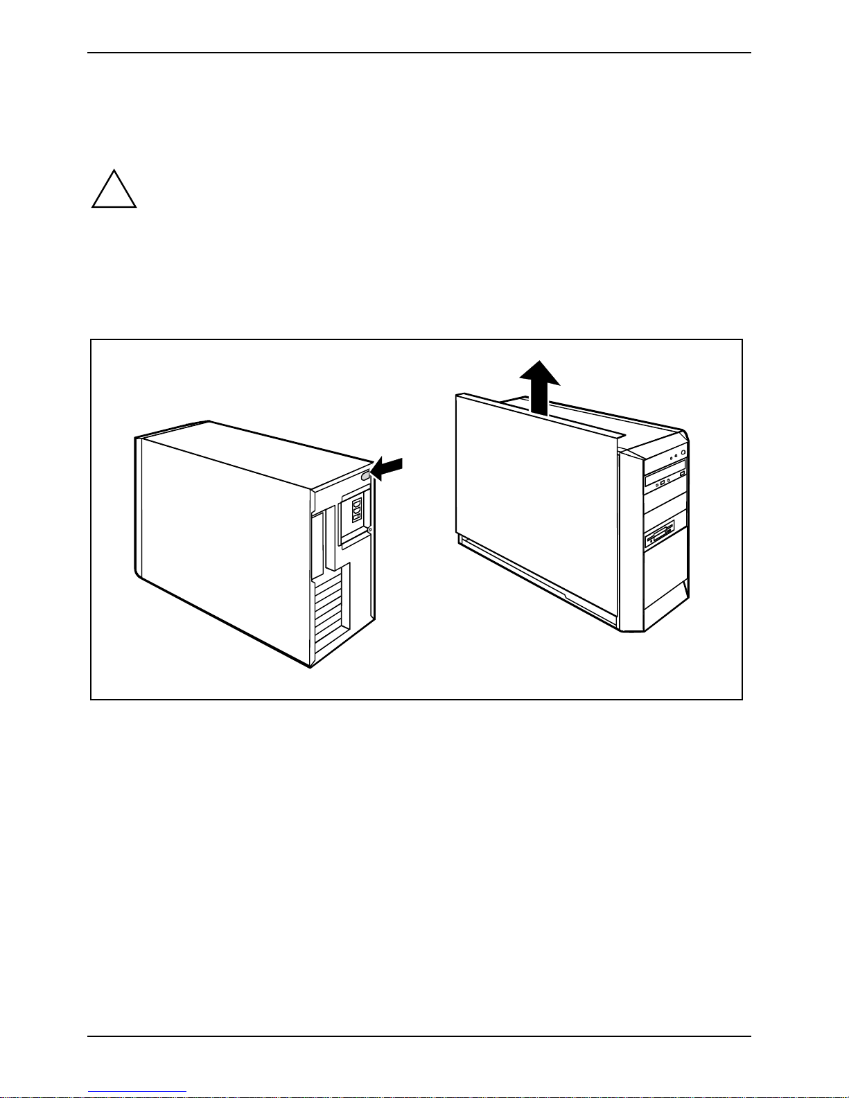
2
1
Ê Press the green unlocking button on the rear of the casing (1).
Ê Hold the green unlocking button depressed and slide the casing side c over upwards in the
direction of the arrow (2).
Ê Pull the side cover out of the c asing.
36 A26361-K831-Z102-1-7619
Page 41
Closing the casing System expansions
Closing the casing
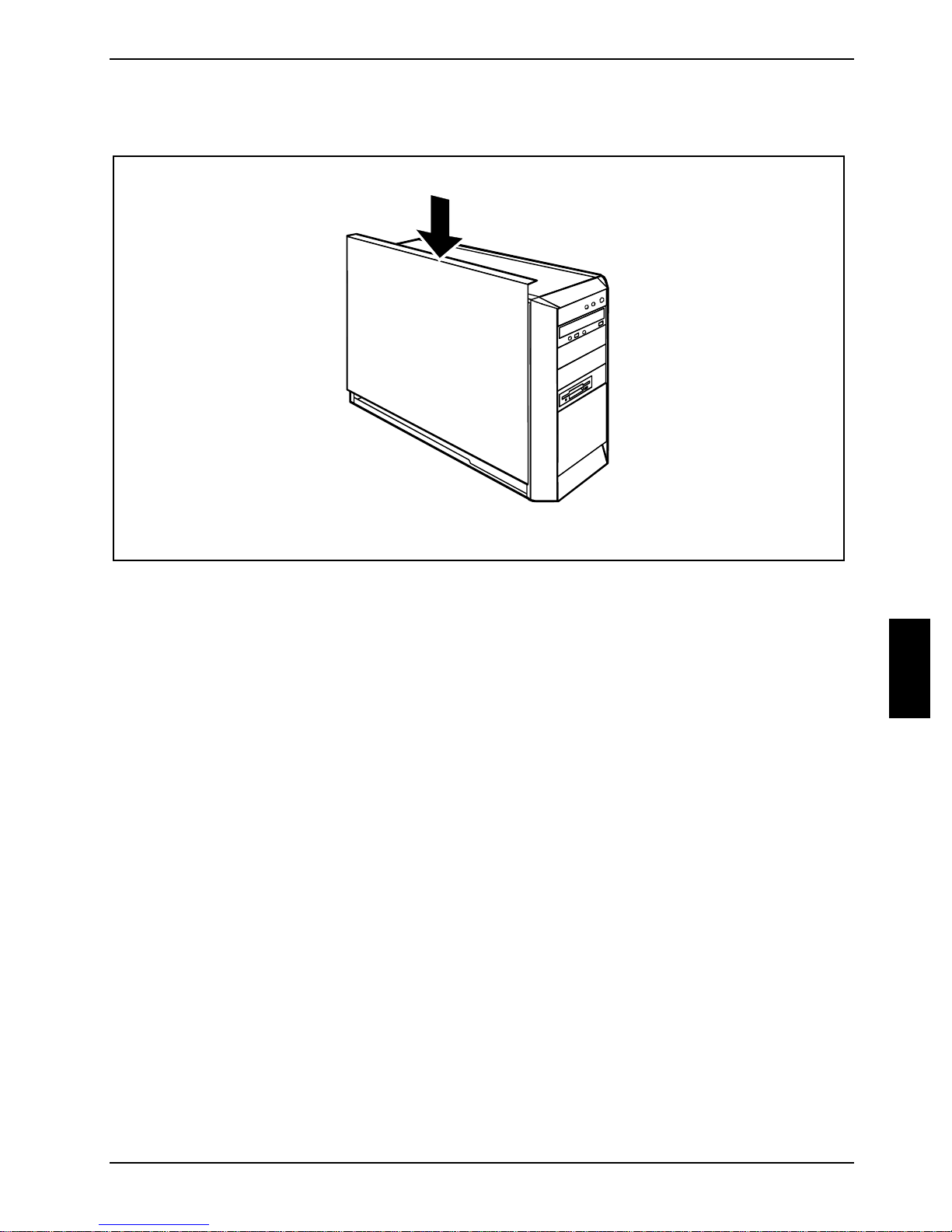
1
Ê Push the side cover from above in t he di rection of the arrow (1) until i t engages.
Ê Return the system unit to its original position.
Ê Reconnect any disconnected cabl es (power cord, cables to external devices, etc.).
A26361-K831-Z102-1-7619 37
Page 42
System expansions Installing and removing a board
Installing and removi ng a board
CAUTION!
!
The number, position and arrangement of the board slots on the system board can be found i n t he
technical manual f or the system board. Boards may already be ins talled when the device is shipped.
Installing a board
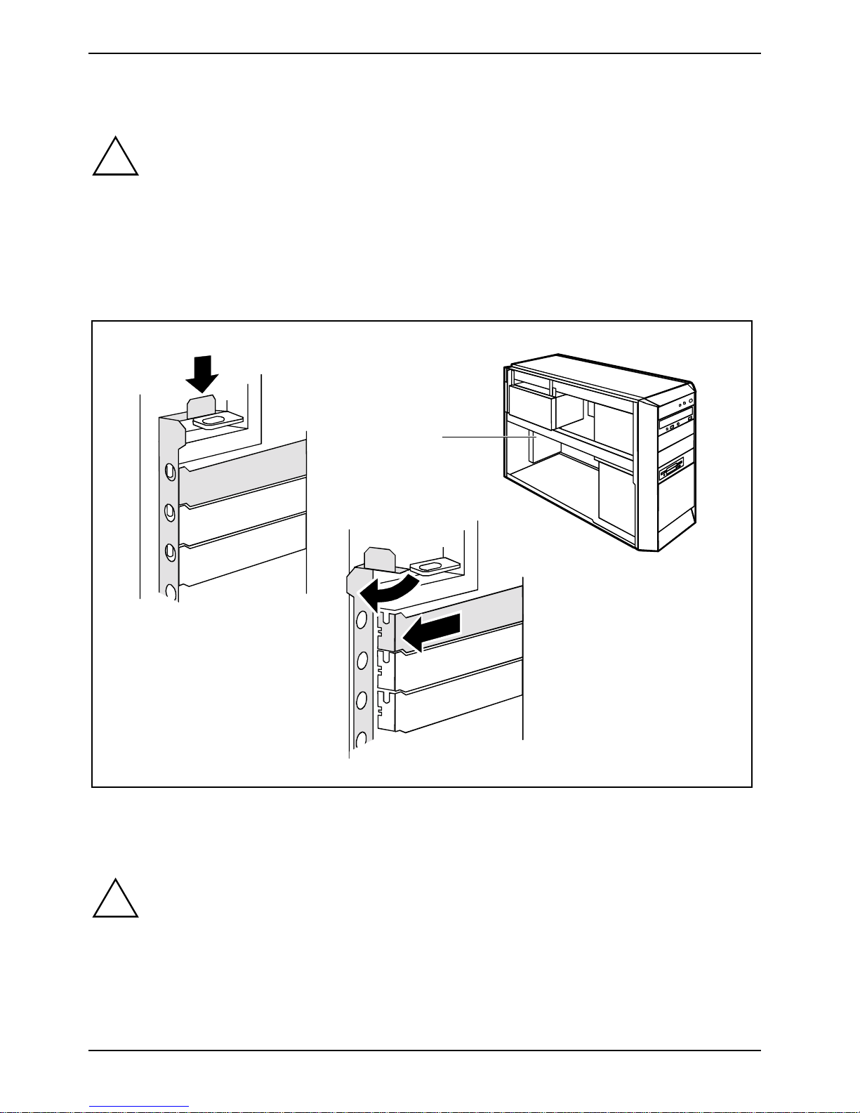
Ê Open the casing (see "Opening the casing").
Please take note of the "Information about boards ".
1
2
3
Ê Press the unlocking mechanism (1) down and open the locking rail (2). The word "PRESS" is
embossed on the unlock i ng mechanism.
Ê Remove the slot cover from the slot (3).
CAUTION!
!
Ê Take the new board out of its packaging.
Ê Make the required settings for the board.
Do not dispose of the slot cover. For cool i ng, protection against f i re and i n order to comply
with EMC regulations , you must refit the slot cover if you remove the board.
38 A26361-K831-Z102-1-7619
Page 43

Installing and removing a board System expansions
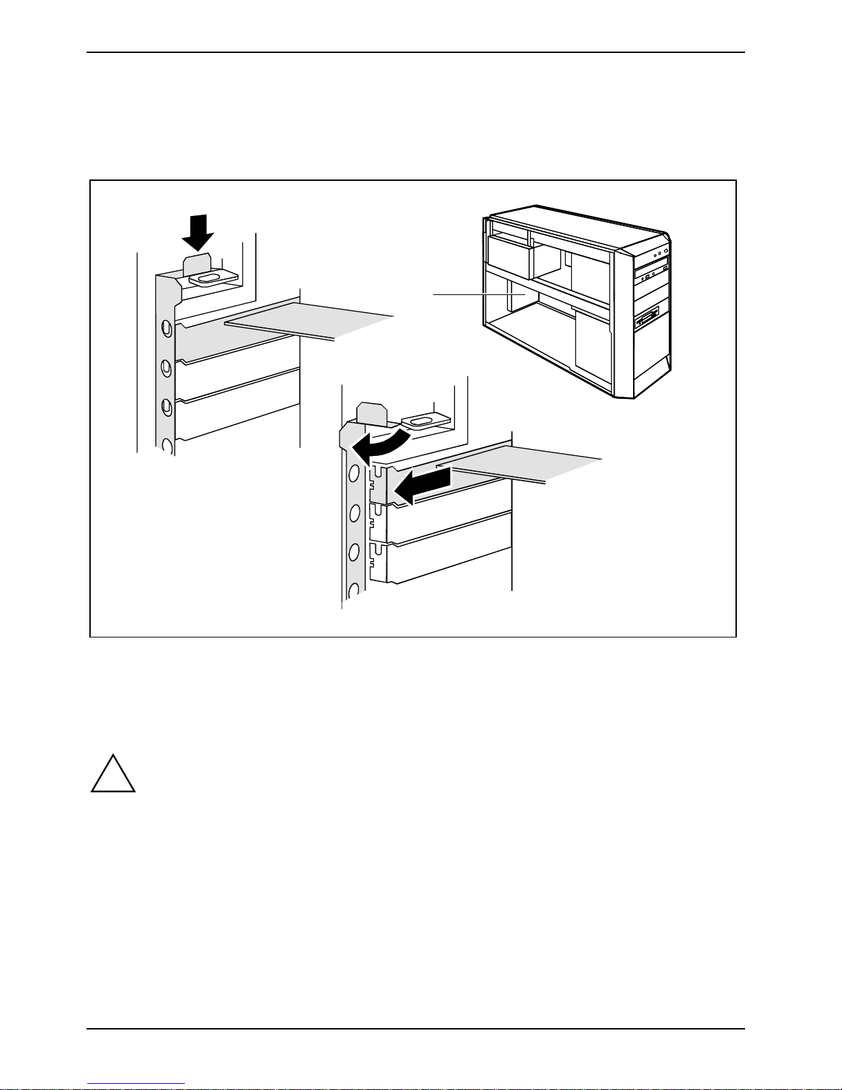
1
3
2
Ê Push the board up to its slot (1).
Ê Press the board into the slot so t hat it engages.
Ê If necessary, connect the cables.
Ê Close the locking rail (2) and press on the l ocking mechanism i n the direction of the arrow (3).
The word "PUSH" is embos sed on the locking mec hani sm.
Ê Close the casing (see "Closing the casing").
If you have installed or removed a PCI board, please check the relevant PCI slot settings in
i
the BIOS Setup. If necessary, change the settings. Further information is provided in the PCI
board documentation.
The slots 1, 3, 5 and 7 are suitable for low-profile cards with an adapter. The slots are
counted from the bottom to the top.
A26361-K831-Z102-1-7619 39
Page 44
System expansions Installing and removing a board
Removing a board
Ê Open the casing (see "Opening the casing").
Ê Disconnect the cables connec t ed to the board.
1
2
3
Ê Press the unlocking mechanism (1) down and open the locking rail (2). The word "PRESS" is
embossed on the unlock i ng mechanism.
Ê Pull the board out of the slot (3).
Ê Place the board into appropriate packaging.
CAUTION!
!
For cooling, protect i on agai nst fire, and in order to comply with EMC (elec tromagnetic
compatibility) regulations, you must refit the slot cover.
40 A26361-K831-Z102-1-7619
Page 45
Installing and removing a board System expansions
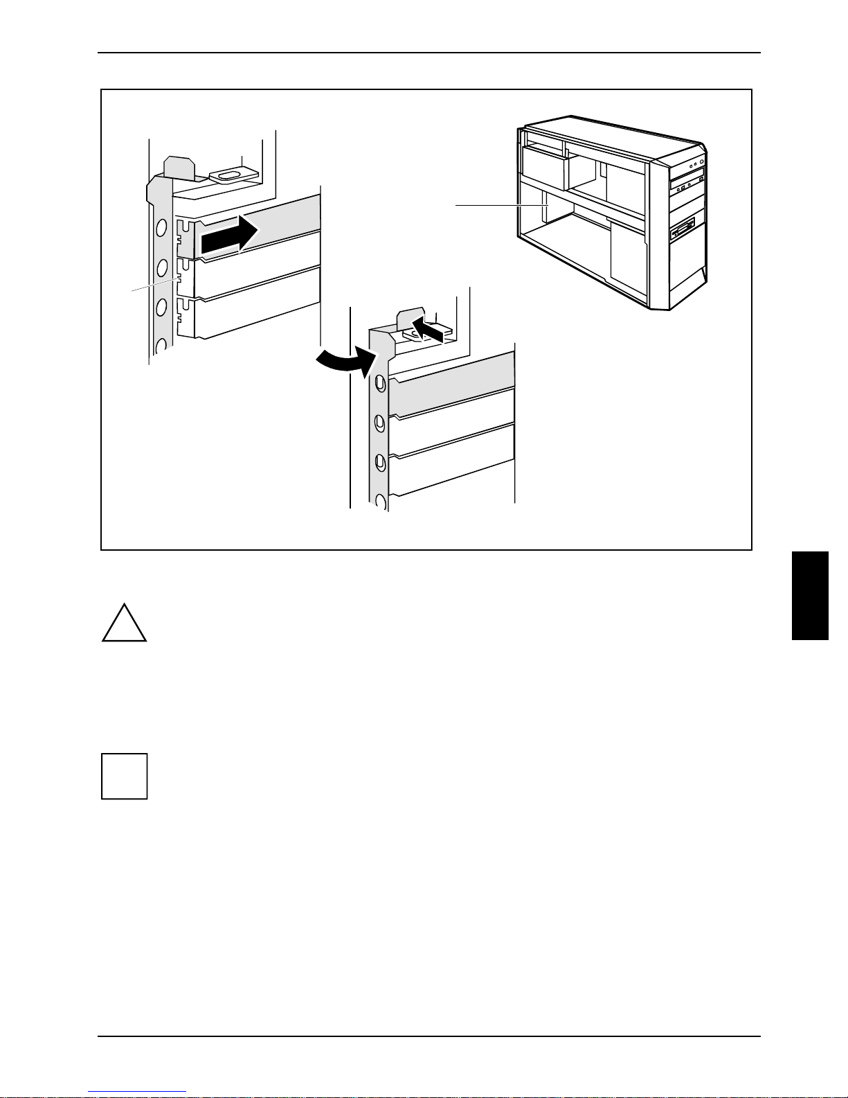
1
a
3
2
Ê Push the slot cover into the slot (1).
CAUTION!
!
Ê Close the locking rail (2) and press on the l ocking mechanism i n the direction of the arrow (3).
Ê Close the casing (see "Closing the casing").
i
Ensure that the projec tion (a) on the slot cov er engages into the appropriate reces s. If it
does not, you will find it dif f i cult to close the lock i ng rail. There is a danger of damage.
The word "PUSH" is embos sed on the locking mec hani sm.
If you have installed or removed a PCI board, please check the relevant PCI slot set tings
in the BIOS Setup. If neces sary, change the set tings. Further informat i on i s provided in the
PCI board documentation.
A26361-K831-Z102-1-7619 41
Page 46
System expansions Low-Profile boards
Low-Profile boards
For units with a particularly low overall height, there are so-called low-profile boards with a slot cover
with a lower overall height to match the low-profil e uni ts. To also inst al l these low-profile boards in
normal board slots, you must mount a corresponding slot adapter beforehand
Two-piece rear covers are fi tted into the slots intended for low-profile boards . The two pieces are
connected together with a screw.
Ê Remove the desired rear cover and then remove the screw.
Mounting slot adapter
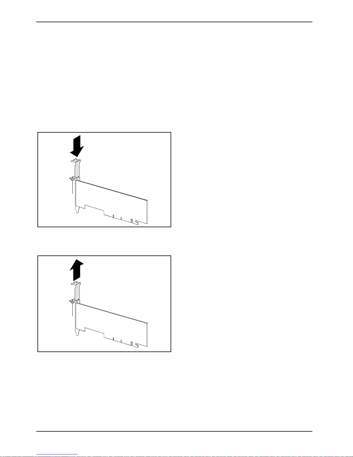
Ê Fit the slot adapter on the slot cov er of the
low-profile board (1) and screw it on (2).
1
Now you can install t he low-profile board in a
suitable slot l i ke a normal board (see the chapter
"Installing board" ).
2
Removing slot adapter
2
1
Ê Unscrew the screw (1) and remove the slot
adapter (2).
42 A26361-K831-Z102-1-7619
Page 47
Low-Profile boards System expansions
Installing and removing drives
The server casing can accommodate a total of eight drives:
• four accessibl e dri ves
(three 5¼" drives and one 3½" dri ve)
• four non-accessibl e dri ves
(3½" drives)
"Access i bl e dri ves" are e.g. DVD or CD ROM drives, into which a data carrier can be inserted f rom
outside. Non-accessible drives are e. g. hard di sk drives.
IDE drives
Four IDE drives are support ed as standard equipment. Ideal l y, hard disk drives are connected to
IDE interface 1 and ot her dri ves to IDE interf ace 2 (see also the techni cal manual for the system
board).
SCSI drives
If you want to ins tall a SCSI drive, you require a SCSI controll er and a SCSI cable. Detail s are
provided in the manuals on t he SCSI controller
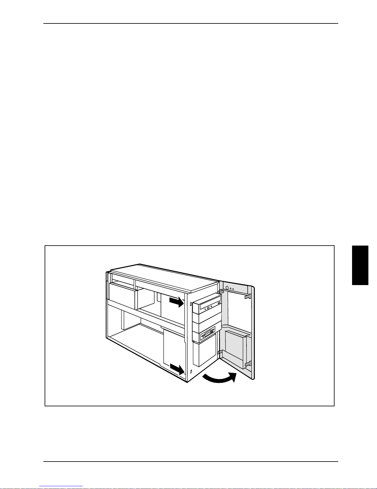
Removing the front panel
Ê Open the casing (see "Opening the casing").
Ê Detach the unlocking lever (1) and open the front panel (2).
1
1
2
Ê Detach the plastic hook on the front panel of the casing and careful l y remove the front panel. I f
you pull too hard, you may loosen or damage the LCD cable.
A26361-K831-Z102-1-7619 43
Page 48
System expansions Low-Profile boards
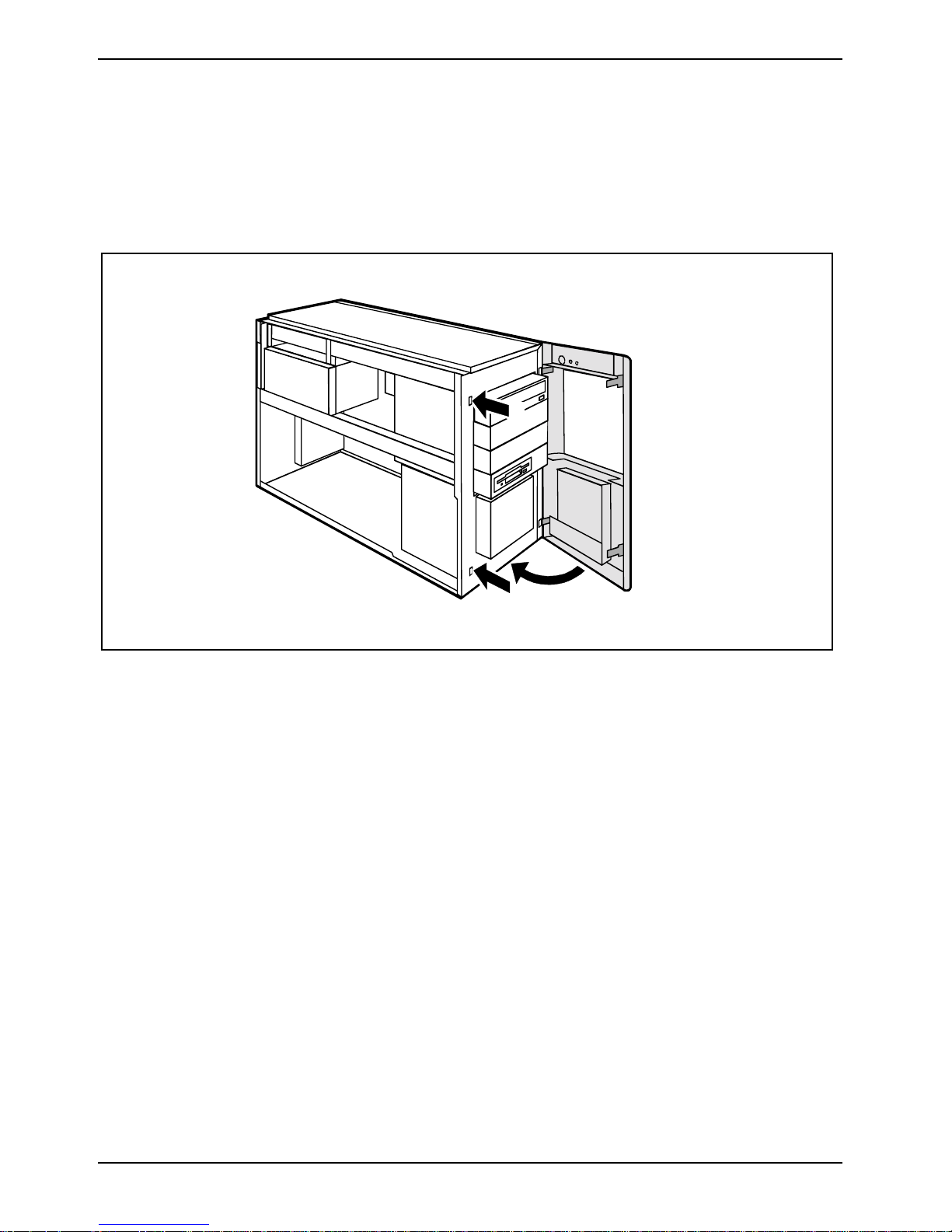
Attaching the front panel
Ê Engage the locking mechanism on the right of the casing. A ttach the front panel on t he casing
such that the plastic hooks engage int o t he correct recesses.
Ê Close the front panel (1) and make sure that t he LCD cable is not pinched and that the locking
mechanisms engage not i ceably (2).
2
1
2
44 A26361-K831-Z102-1-7619
Page 49
Low-Profile boards System expansions
Installing an accessible drive
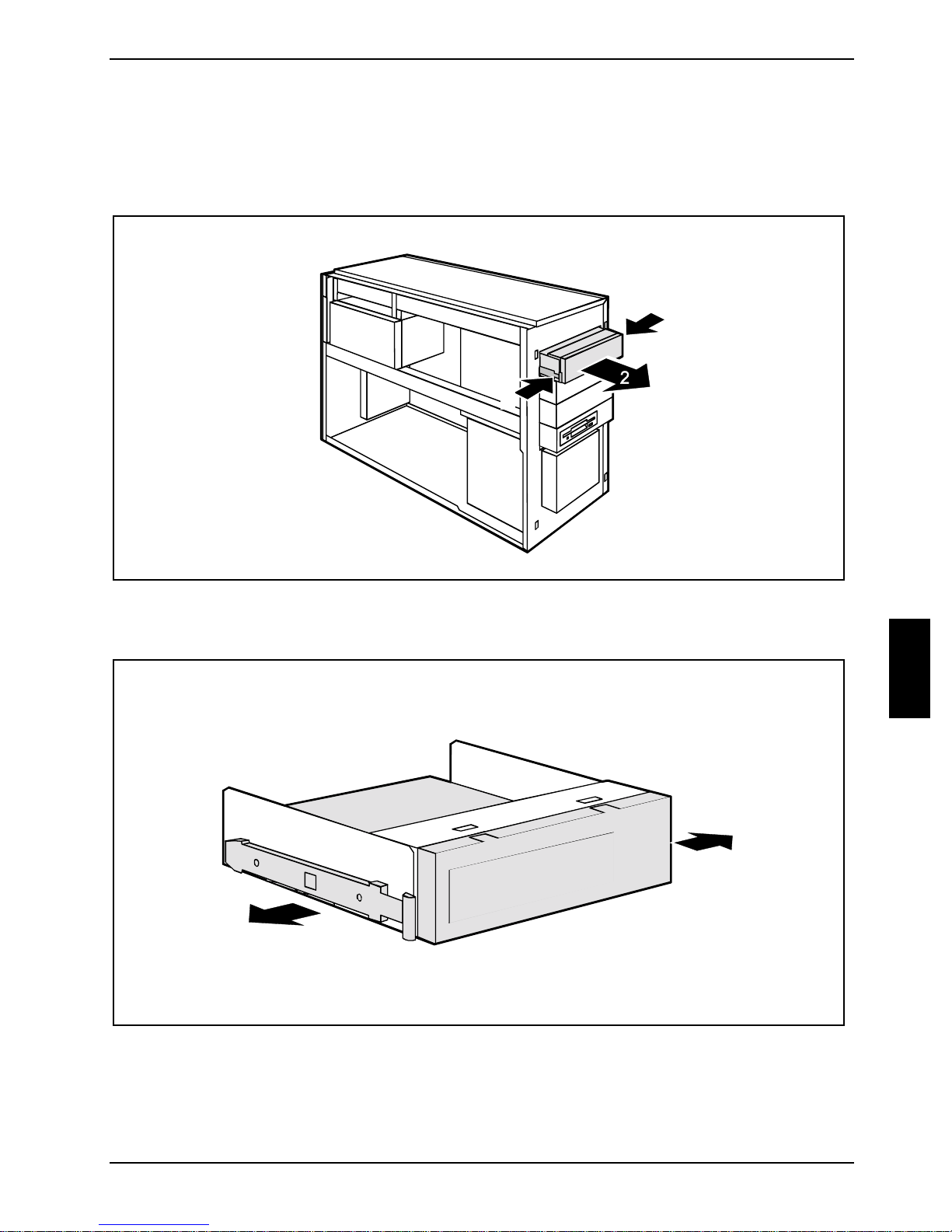
Ê Open the casing (see "Opening the casing").
Ê Remove the front (see "Removing the front panel").
1
1
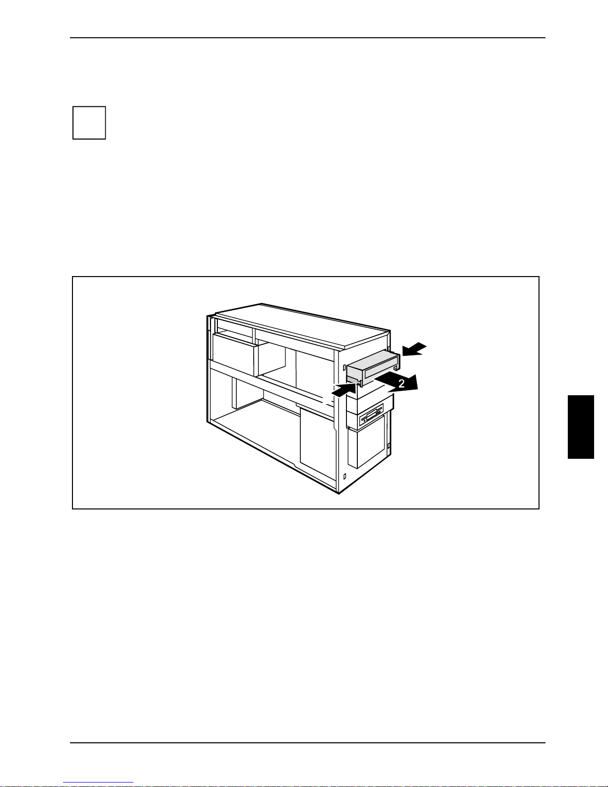
Ê Press the EasyChange rails (1) toget her and pul l the empty slide-in m odul e out of the
casing (2).
A26361-K831-Z102-1-7619 45
Page 50
System expansions Low-Profile boards
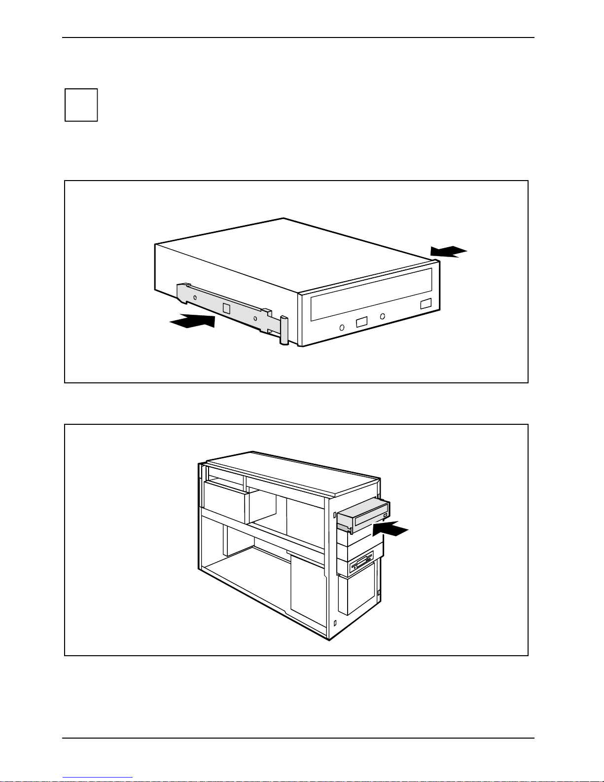
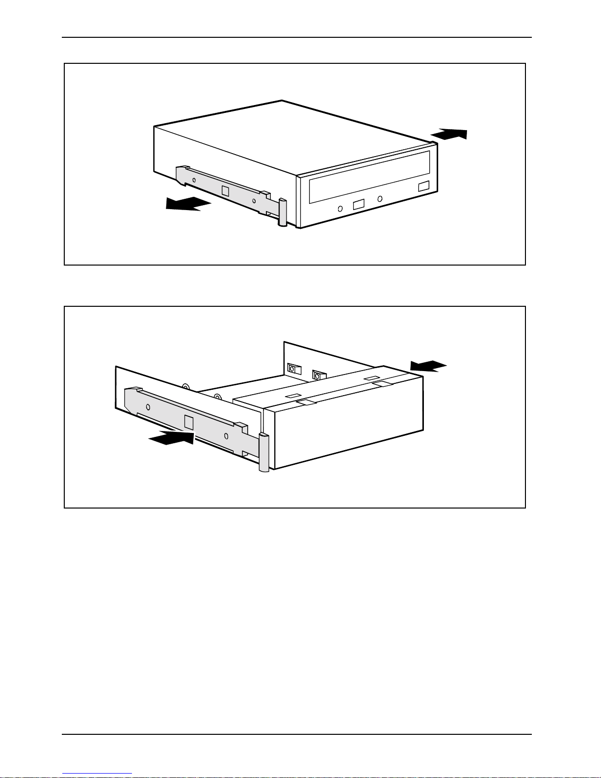
Ê Pull the EasyChange rails off t he em pty slide-in module.
Do not dispose of the em pt y slide-in module. For c ool i ng, protection against f i re, and i n
i
Ê Take the new drive out of its packagi ng.
Ê Adjust the required settings on t he dri ve (if necessary, on already-installed drives as well).
order to comply wit h E M C regul ations, you must refit the empty slide-in module if you
remove the drive again lat er.
Ê Press the EasyChange rails into the provided holes.
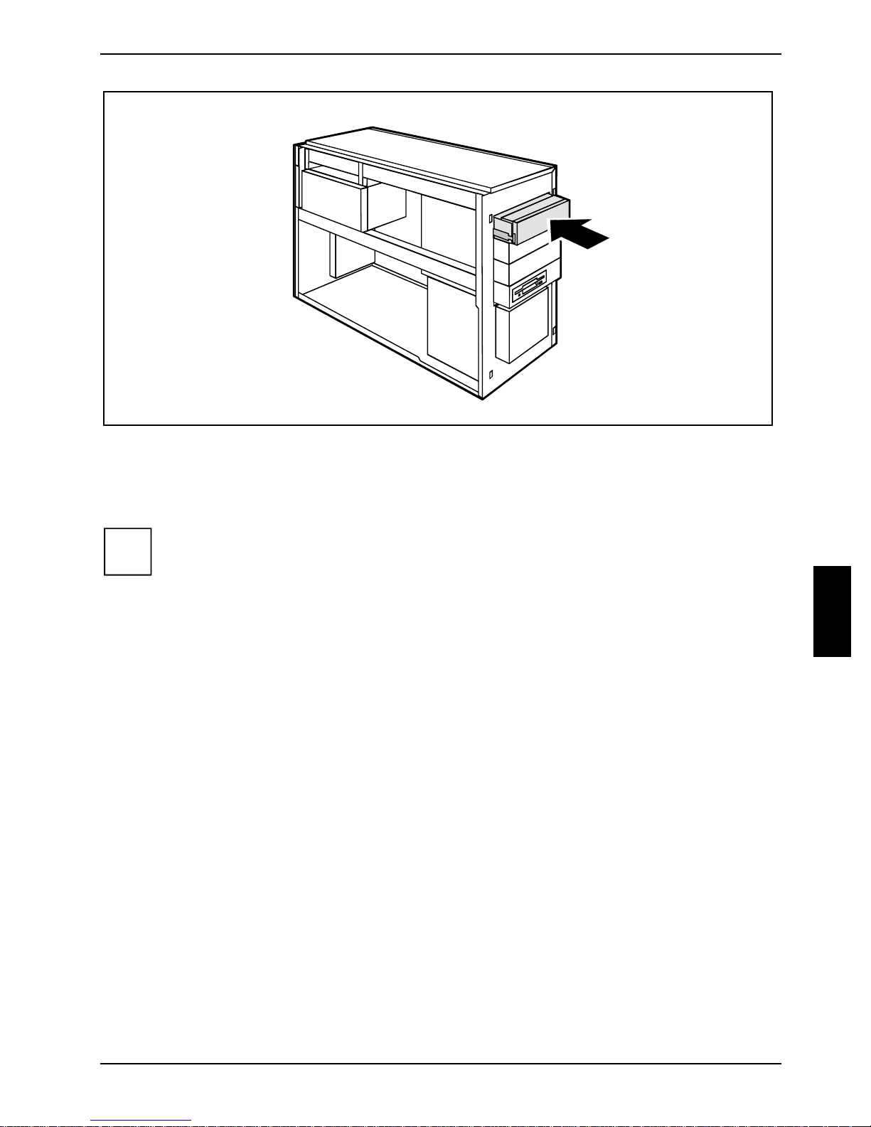
Ê Push the accessible drive into the casing until the EasyChange rails engage.
Ê Plug the data and the power supply connectors into the drive. Make sure the polarity is correct.
46 A26361-K831-Z102-1-7619
Page 51
Low-Profile boards System expansions
Ê Attach the front panel (see "At t aching the front panel").
Ê Close the casing (see "Closing the casing").
With the upper three accessible drives, the EasyChange rail is at tached at the bottom of
i
the module.
The rail is attached at the center of the module on t he l owest drive.
All rails are mounted correctly on deliv ery.
It may be necessary to modify t he entry for the drive in t he BIOS Setup.
Removing an accessible drive
Ê Open the casing (see "Opening the casing").
Ê Remove the front (see "Removing the front panel").
1
1
Ê Pull the data and the power supply connect ors from the desired drive.
Ê Press the EasyChange rails toget her (1) and pul l the drive out of the cas ing (2).
Ê If necessary, make the required settings on the remaini ng hard di sk drive.
A26361-K831-Z102-1-7619 47
Page 52
System expansions Low-Profile boards
Ê Pull the EasyChange rails off t he dri ve.
Ê Press the EasyChange rails into the holes provided in the empt y slide-in module.
48 A26361-K831-Z102-1-7619
Page 53
Low-Profile boards System expansions
Ê Slide the slide-in module into the casing until it engages not i ceably.
Ê Attach the front panel (see "At t aching the front panel").
Ê Close the casing (see "Closing the casing").
i
It may be necessary to modify t he entry for the remaining drives in the BIOS Setup.
A26361-K831-Z102-1-7619 49
Page 54
System expansions Low-Profile boards
Changing the floppy disk drive
Ê Open the casing (see "Opening the casing").
Ê Remove the front (see "Removing the front panel").
Ê Disconnect the cables connec t ed to the floppy disk dri ve.
Removing the floppy disk drive
1
1
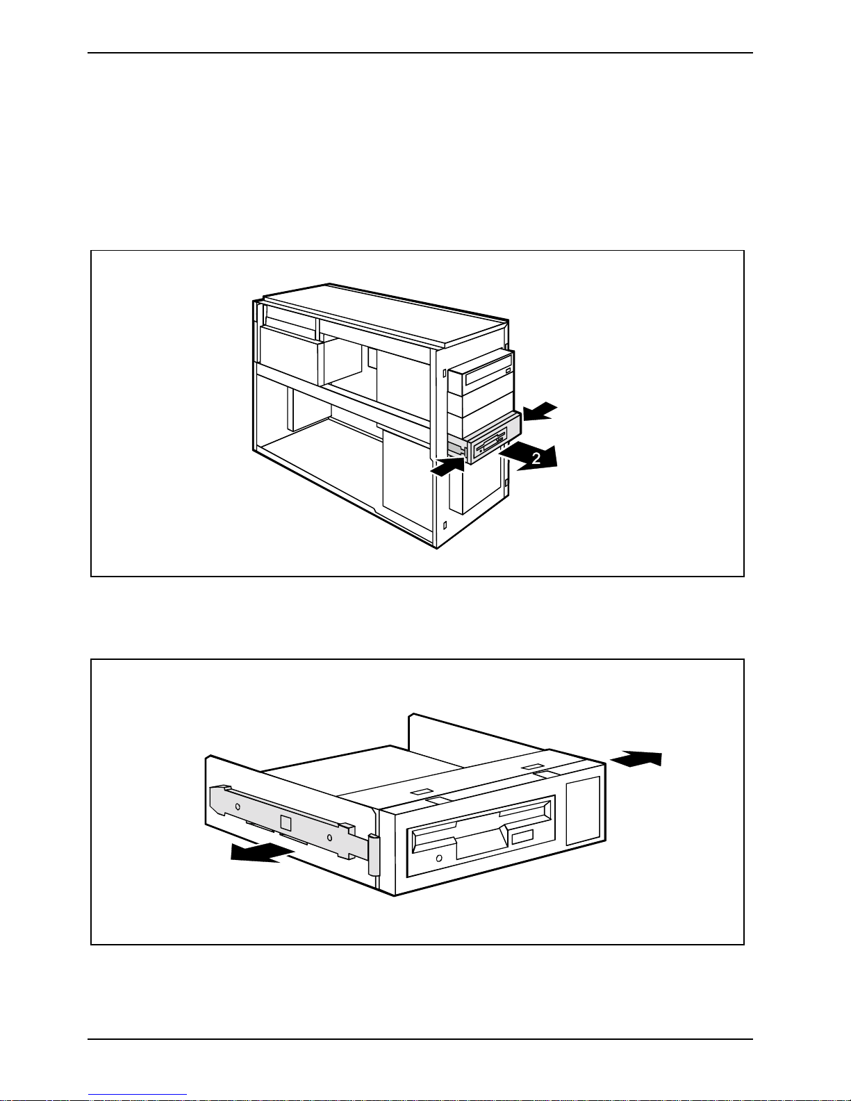
Ê Press the EasyChange rails in t he di rection of the arrows (1).
Ê Pull the floppy disk drive s l i de-i n module out of the casing (2).
Ê Pull the EasyChange rails off t he floppy disk drive slide-in module.
50 A26361-K831-Z102-1-7619
Page 55
Low-Profile boards System expansions
1
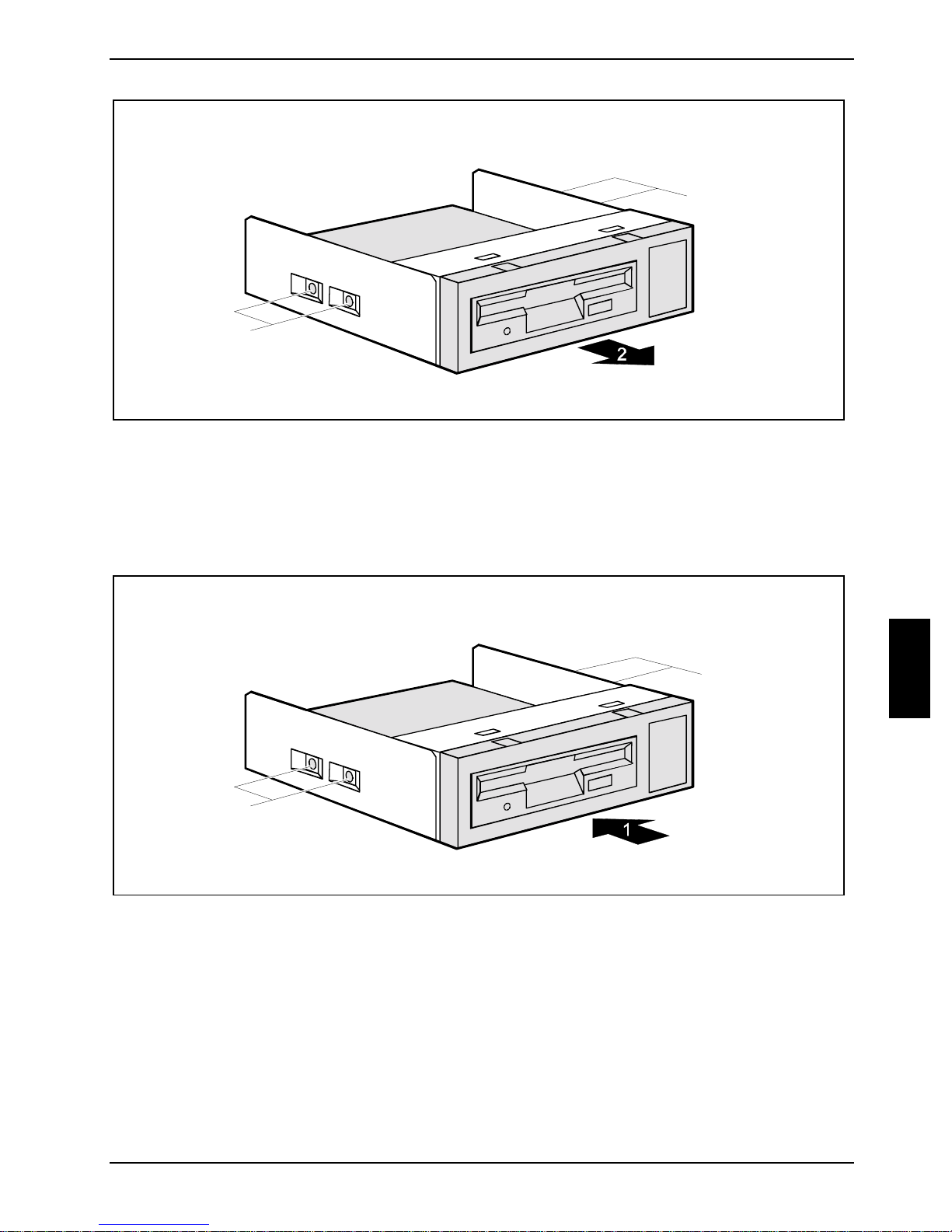
1
Ê Remove the screws (1) on both sides of t he slide-in module.
Ê Pull the floppy disk drive out of the slide-in module (2).
Installing the floppy disk drive
Ê Take the new floppy disk drive out of i t s packaging.
2
2
Ê Slide the floppy disk drive into the slide-in module (1).
Ê Fasten the floppy disk drive with the screws (2) on both s i des of the slide-in module.
A26361-K831-Z102-1-7619 51
Page 56
System expansions Low-Profile boards
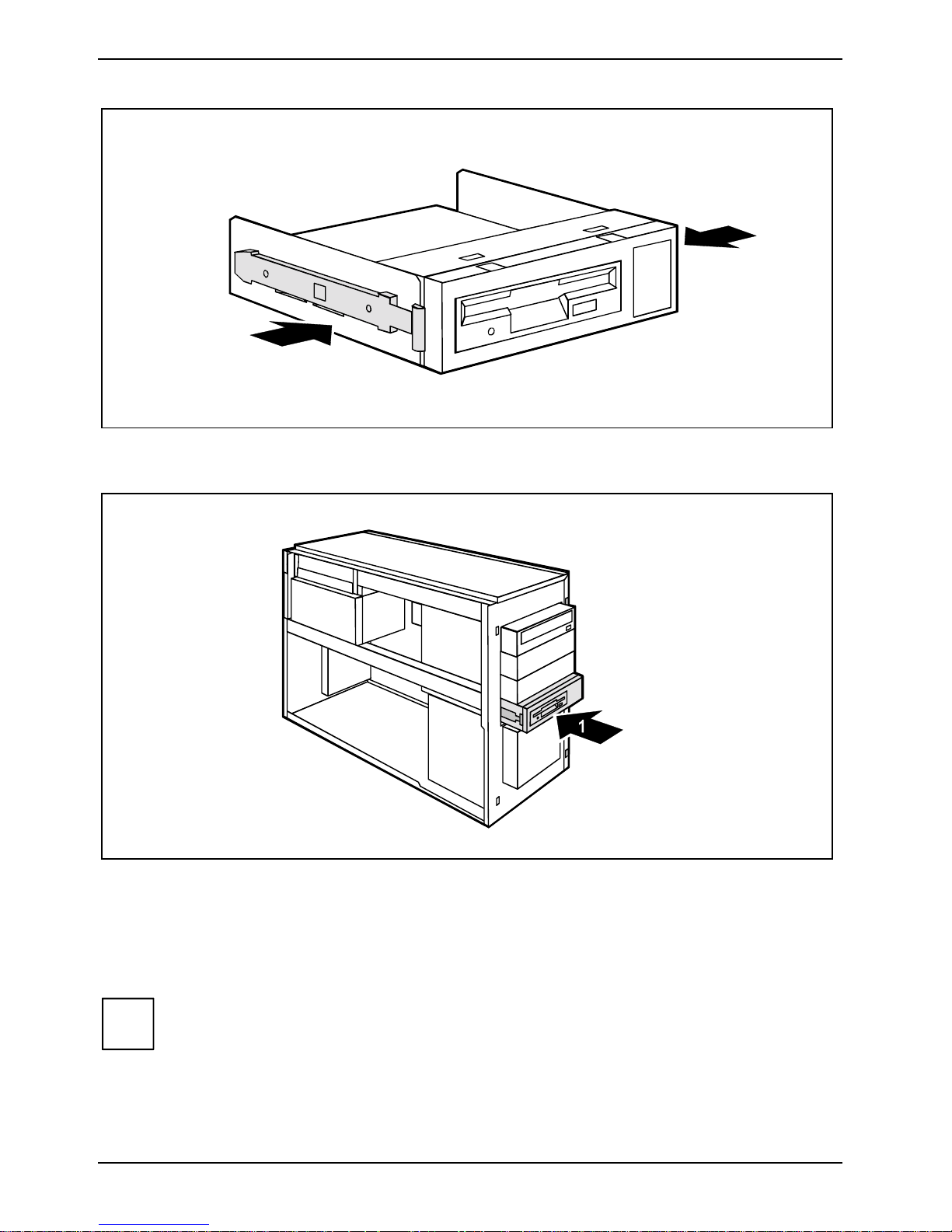
Ê Press the EasyChange rails into the provided holes.
Ê Slide the floppy disk drive s l i de-i n module into the casing (1) unt i l it engages noticeably .
Ê Fit the data and power supply connectors t o the floppy disk drive.
Ê Attach the front panel (see "At t aching the front panel").
Ê Close the casing (see "Closing the casing").
i
It may be necessary to modify t he entry for the drive in t he BIOS Setup.
52 A26361-K831-Z102-1-7619
Page 57
Low-Profile boards System expansions
Installing or removing the hard disk drive
Ê Open the casing (see "Opening the casing").
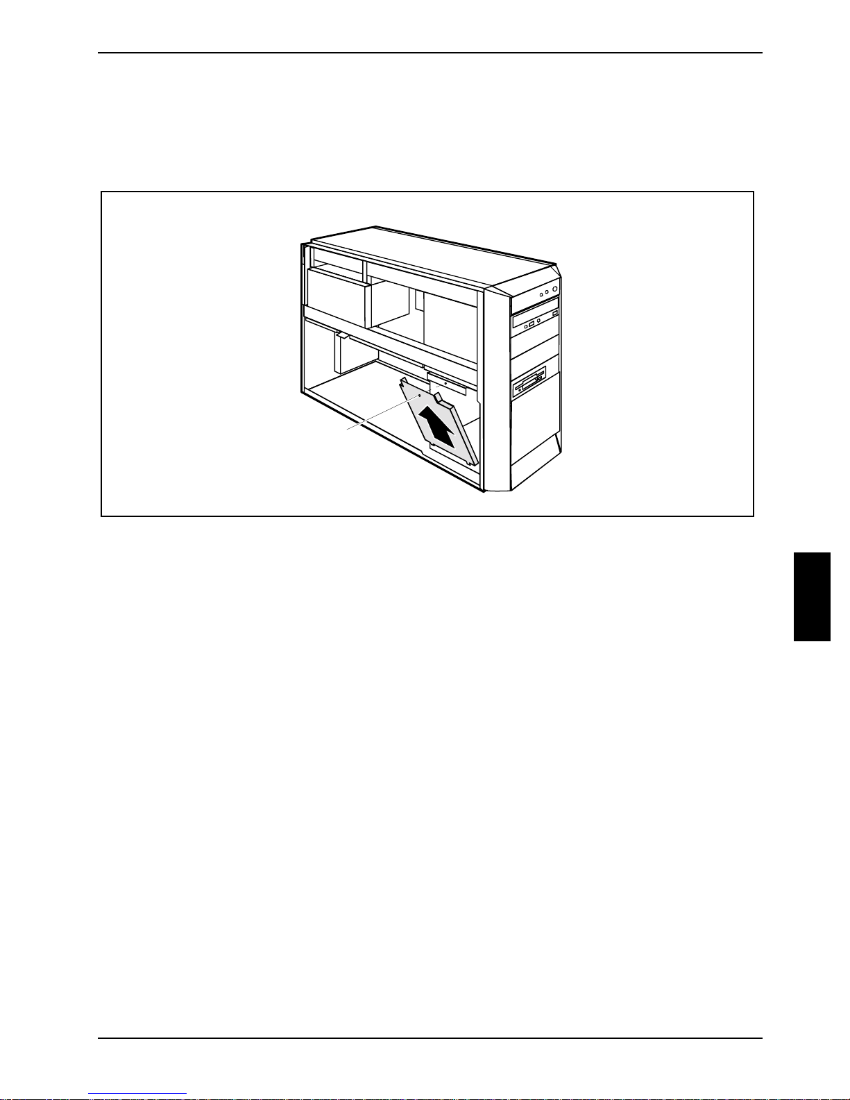
Removing the cover
Ê Undo the screw (1).
Ê Fold out the cover (2).
1
2
A26361-K831-Z102-1-7619 53
Page 58
System expansions Low-Profile boards
Installing a hard disk drive
Ê Take the new hard disk drive out of its packaging.
Ê Make the required settings (e.g. master-slave set t ings) on the drive.
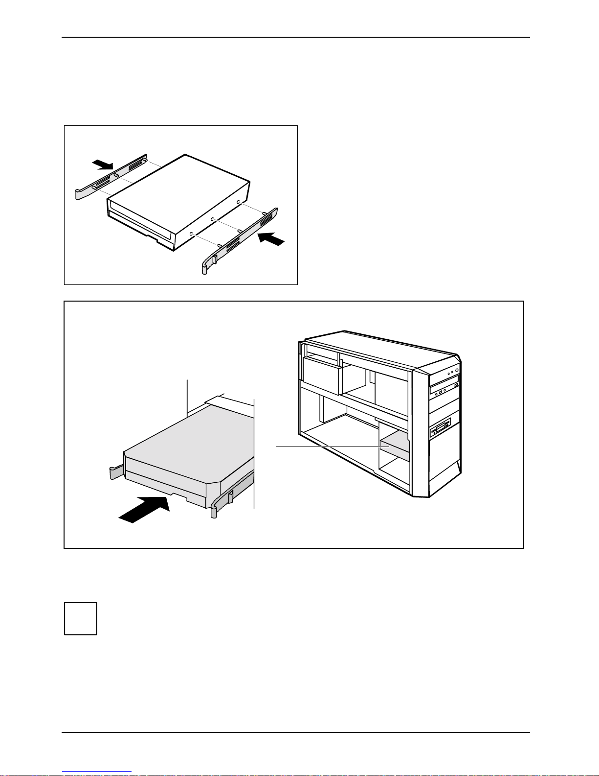
Ê Secure the EasyChange rails on the si de of
the hard disk drive by i nserting the upper
pins of the Easy Change rai l i n the
corresponding holes of t he hard di sk drive.
1
Ê Push the hard disk drive into the c asing (1) until the EasyChange rails engage.
Ê Connect the data and power supply cables to the hard disk drive or to t he hard di sk drives.
Connect the blue plug of the data cable to the connect i on on the system board. Connect
i
the plug on the other end to the hard disk drive.
54 A26361-K831-Z102-1-7619
Page 59
Low-Profile boards System expansions
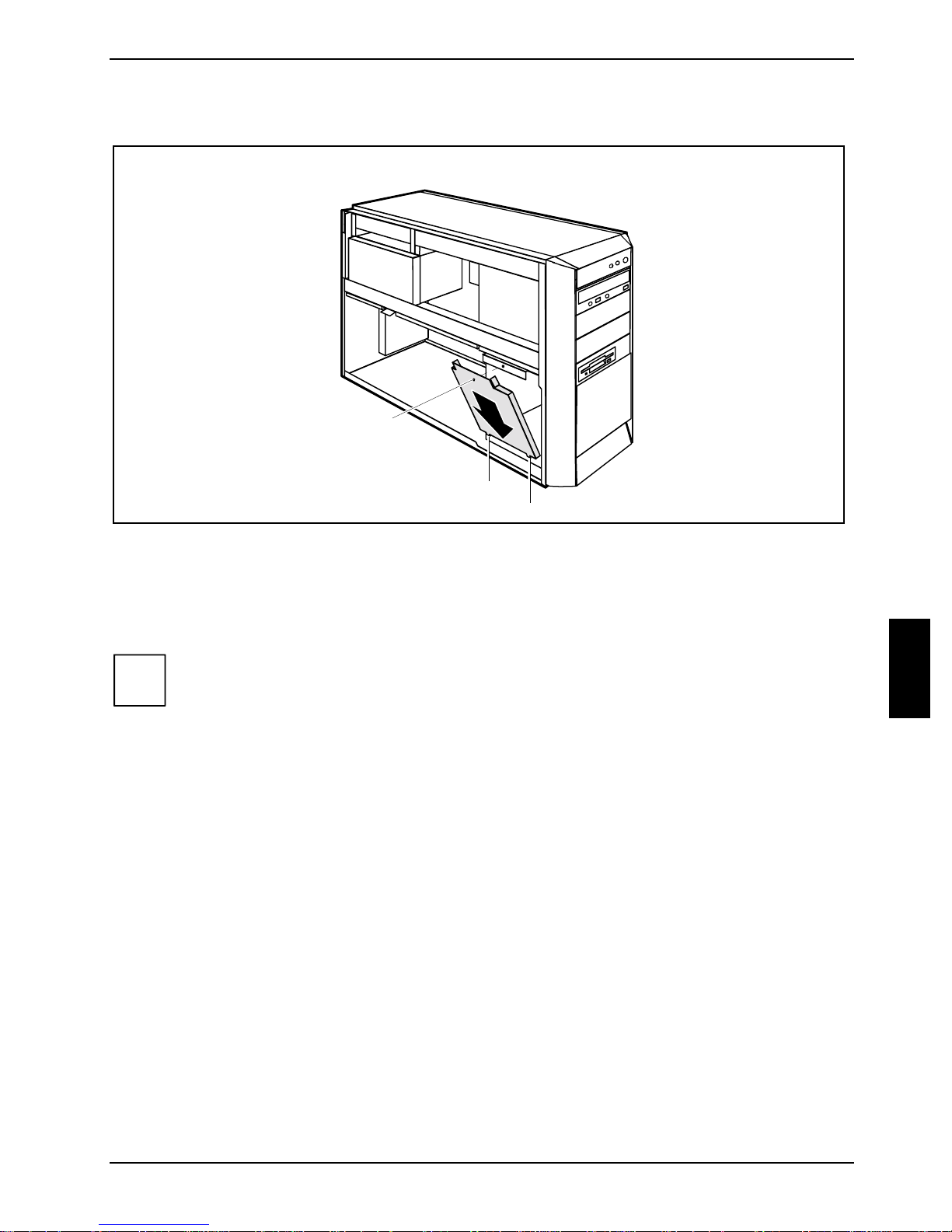
Installing the cover plate
2
1
a
a
Ê Set the cover plate into the cas i ng such that the projections (a) engage into the appropriate
recesses (1).
Ê Close the cover and fasten it with the screw (2).
Ê Close the casing (see "Closing the casing").
i
It may be necessary to modify t he entry for the drive in t he BIOS Setup.
A26361-K831-Z102-1-7619 55
Page 60
System expansions Low-Profile boards
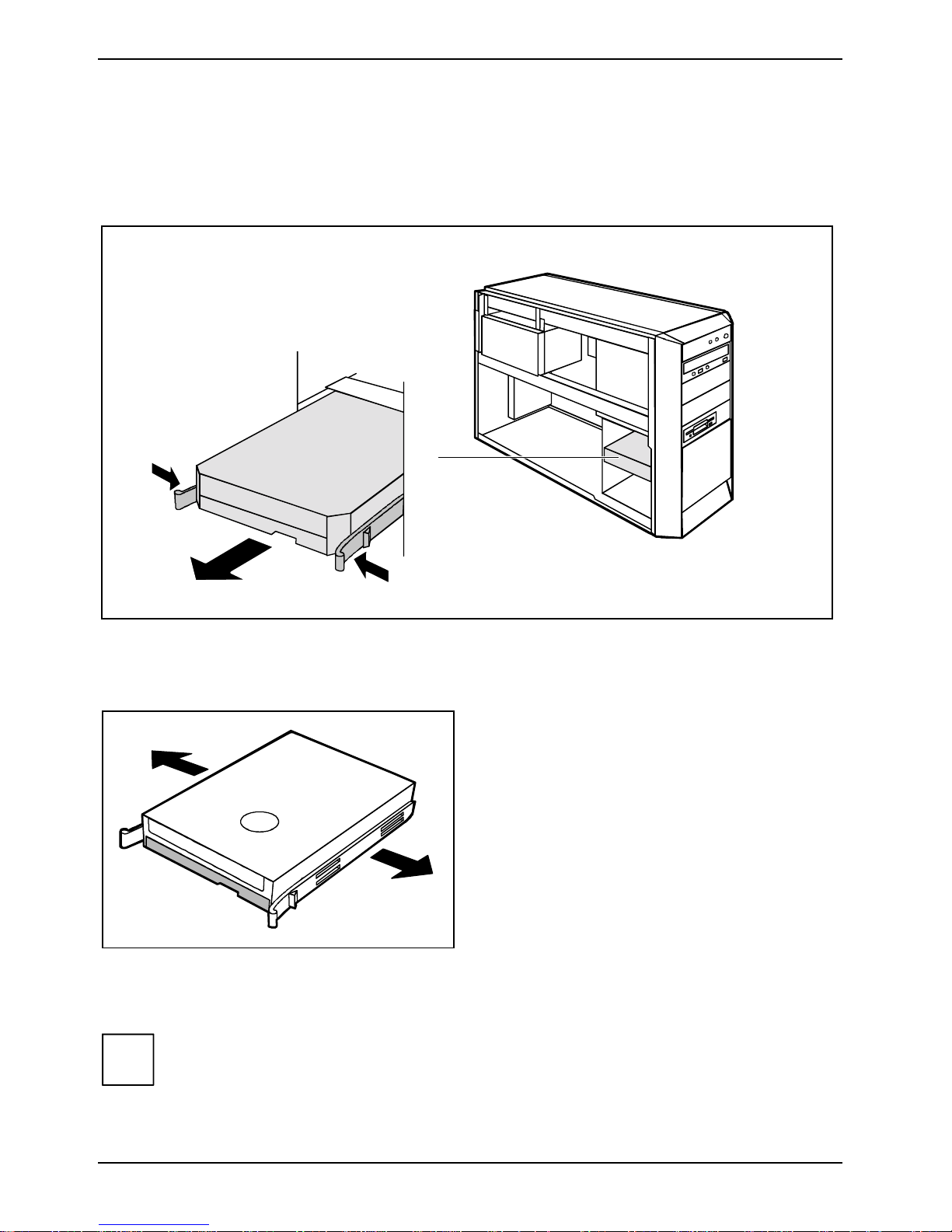
Removing a hard disk drive
Ê Open the casing (see "Opening the casing").
Ê Remove the cover (see "Removing the cover").
Ê Disconnect all cables connec ted to the drive (data cabl e, power supply cable).
1
2
1
Ê Press the EasyChange rails in t he di rection of the arrows (1).
Ê Take the hard disk drive out of the carri er (2).
Ê Pull the EasyChange rails off t he hard di sk
drive.
If necessary , make the required sett i ngs on the
remaining hard disk driv e.
Ê Install the cover plate (see " I nstalling the cov er pl at e").
Ê Close the casing (see "Closing the casing").
i
It may be necessary to modify t he entry for the drive in t he BIOS Setup.
56 A26361-K831-Z102-1-7619
Page 61

Extensions to the system board System expansions
Extensions to the system board
Details on whether you c an upgrade the main memory or the processor are provided in the tec hni cal
manual for the system board. In order to upgrade or replac e the processor, you must first remov e
the ventilation cover.
Ê Open the casing (see "Opening the casing").
Removing the power supply
1
2
Ê Unscrew the screw with which the power s uppl y is secured in the casing (1).
Ê Swing the power supply out of the casing as far as it will go (2).
CAUTION!
!
Only connect the power pl ug after you have reinstal l ed t he power supply and closed the
unit.
Upgrading main memory
Ê Upgrade the memory according to the descri ption in the technical m anual for the system board.
Ê Close the casing (see "Closing the casing").
Replacing processor
Ê Upgrade the processor according to the description in the techni cal manual for the system
board.
A26361-K831-Z102-1-7619 57
Page 62
System expansions Extensions to the system board
Replacing lithium battery
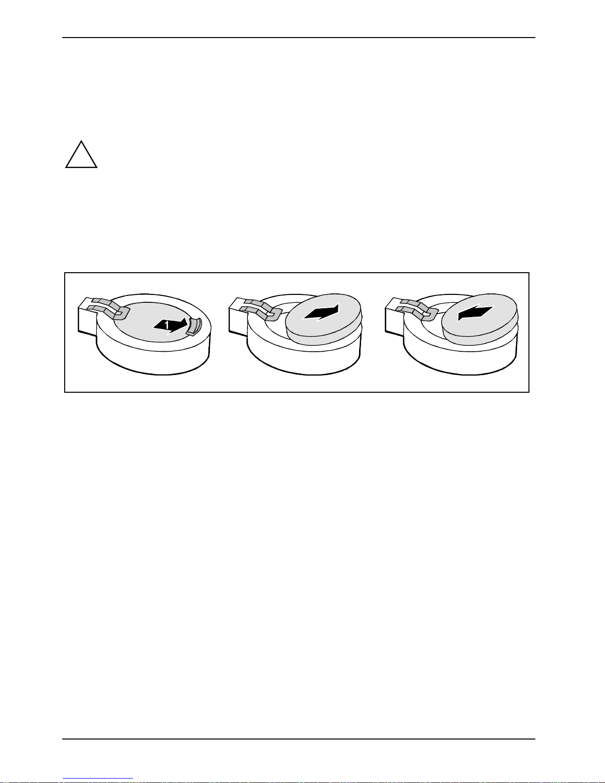
In order to permanently s ave the system information, a lithium battery is installed to provide the
CMOS-memory with a c urrent. A corresponding error mes sage notifies the us er when the charge is
too low or the battery is empty. The lithi um battery must then be repl aced.
CAUTION!
!
Incorrect replacem ent of the lithium battery may lead to a ris k of explosion!
The lithium battery m ay be replaced only with an ident i cal battery or with a t ype
recommended by the manufacturer.
Do not throw lithium batteries into the household waste. They must be di sposed of in
accordance with local regulations concerni ng special waste.
Make sure that you i nsert the battery the ri ght way round. The plus pole mus t be on the
top!
2
3
Ê Press the locking lug in the direction of the arrow; the battery jumps somewhat out of the
holder (1).
Ê Remove the battery (2).
Ê Push the new lithium battery of t he identical type int o the holder (3) and press it downward until
it engages (4).
Swinging the power supply in
Ê Swing the power supply into the casing unt i l i t meets the stop.
Ê Fasten the power supply in the casing with the screw.
58 A26361-K831-Z102-1-7619
Page 63
Technical data
Electrical data
Regulations compli ed wi th: EN 60950 / VDE 0805
UL 1950
CSA 22.2 No.950
Protection class: I
Rated voltage range (automati c, 300 W power
supply)
Frequency: 50 Hz - 60 Hz
Max. rated current
• Server with monitor outlet:
100 V - 240 V
100 V - 127 V / 7,0 A
200 V - 240 V / 3,5 A
• Monitor socket (output): 100 V - 127 V / 3.0 A
200 V - 240 V / 1,5 A
Dimensions
Width/depth/height: 205 mm/504 mm/385 mm
Weight
with the basic configuration approx. 15 kg
Environmental conditions
Environment class (3K2)
Environment class (2K2)
Temperature:
• Operating (3K2)
• Transport (2K2)
DIN IEC 721 part 3-3
DIN IEC 721 part 3-2
15 °C .... 35 °C
-25 °C .... 60 °C
Condensation in operating mus t be avoided.
Clearance required to ensure adequate v entilation:
• left
• front
• rear
The data sheet of the server contains further tec hnical data. You will find the data sheet
i
A26361-K831-Z102-1-7619 59
either on the "ServerS t art" CD supplied or on the Int ernet at:
http://www.fujitsu-siemens.com/.
min. 200 mm
min. 200 mm
min. 200 mm
Page 64

Page 65
Index
3 1/2-inch drive 43
5 1/4-inch drive 43
A
Alt Gr key 26
Anti-theft prot ection 28
Audio input 19
Audio output 19
B
Battery 58
BIOS Setup 28
security functions 29
system settings 28
Board 35
installing 38
removing 38, 40
C
Cable
connecting 18
disconnecting 19
Casing
closing 37
lead-sealing 28
locking 37
opening 36
CD-ROM drive
indicator 25
installing 45
removing 47
CE certificate 5
Chain 28
Class B Compliance Statement 6
Configuration
BIOS Setup 28
ServerStart 13
Contents of deliv ery 7
Control key 26
Ctrl key 26
Ctrl+Alt+Del 26
Cursor keys 25
D
Data protection 28
Date, not correct 34
Device drivers
parallel port 20
serial port 20
USB 21
Devices
connecting 18, 20, 21
ports 19
with USB port 21
Devices with USB port, software 21
Disposal 5
Drive 43
accessible 43
installing 43, 45
non-accessible dri ve 43
removing 43, 47
E
Electromagnetic compatibility 5
Energy saving 5
Enter key 25
Ergonomics 8
Error
date 34
floppy disk 33
message 34
mouse 33
screen 32
server 31
time 34
ESD 35
Extensions
server 35
system board 57
External devic es
connecting 18, 20, 21
ports 19
F
FCC statement 6
Floppy disk
cannot read 33
cannot write 33
inserting 27
removing 27
write-protection 27, 33
write-protection, di sabling 27
Floppy disk drive
changing 50
indicator 25
installing 51, 52
removing 50
Floppy disk indic at or 25
Function keys 25
A26361-K831-Z102-1-7619 61
Page 66
Index
G
Game port 19
H
Hard disk contents, restoring 34
Hard disk drive
indicator 24
installing 53, 55
removing 53, 56
Hard disk indicat or 24
Headphones, port 19
I
IDE drive 43
Installation
ServerStart 14
switching on for the first time 11
Installing, software 11, 13
Interfaces 19
K
Kensington Lock 28
Key
Alt Gr 26
Control key 26
Ctrl 26
Ctrl key 26
Ctrl+Alt+Del 26
Enter key 25
Menu key 26
Num Lock 26
Return key 25
Shift 26
Shift key 26
Start key 26
Key combination 25, 26
Keyboard 25
connecting 9
important keys 25
port 9, 19
Keypad, alphanumeric 25
L
LAN port 19
Lead-sealing 28
Line in 19
Line out 19
Lithium battery 57
replacing 58
Low-profile boards 42
mounting slot adapter 42
removing slot adapter 42
M
Main memory 57
upgrading 57
Main switch 12
Manuals, further 34
Memory
insufficient 34
not enough 34
Menu key 26
Microphone jack 19
Monitor
cleaning 6
connecting 8
remains blank 32
transporting 6
Monitor screen, no s creen display 32
Mouse
connecting 9
error 33
pointer 33
port 19
N
New installation, software 31
New software, installing 31
Notational convent i ons 3
Note
boards 35
CE certificate 5
important 5
Num Lock key 26
Numeric keypad 25
O
ON/OFF button 12
P
Packing material 7
unpacking 7
Parallel port 19
connecting devic es 20
settings 20
Port
audio input 19
audio output 19
game port 19
headphones 19
keyboard 19
LAN 19
line in 19
line out 19
microphone 19
monitor 19
mouse 19
62 A26361-K831-Z102-1-7619
Page 67
Index
Port
parallel port 19
printer 19
PS/2 mouse 19
SCSI 19
serial port 19
USB 19
Power supply, remov i ng 57
Power-on indicator 12, 13, 24
dark 31
fails to light 24, 31
lights green 24
lights orange 24
Preparing for first use, overview 7
Preparing for use 7
overview 7
Printer 19
Processor 57
Property protecti on 28
Protection, propert y and data 28
PS/2 mouse
connecting 9
port 9, 19
R
Ready-to-operate 12
Recycling 5
Retransportation 6
Return key 25
S
Safety 5
SCSI drive 43
SCSI port 19
Security functions, BIOS Setup 29
Serial port 19, 20
connecting devic es 20
port 19
settings 20
Server
anti-theft protec t ion 28
cabling 18
cannot boot 31
checking rated vol tage 10
cleaning 6
closing 37
connecting 10
connecting devic es 18
extensions 35
indicator 24
lead-sealing 28
locking 37
opening 36
ports 19
Server
ready for operation 23
setting up 8
soft power off 23
switching off 23
switching off, with main switch 23
switching on 11, 23
switching on, with main switch 23
transporting 6
ServerStart
Expert Mode 16
Guided Mode 15
installation 14
installation mode 15
Preparation Mode 17
Replication Mode 18
using 14
Setup, see BIOS Setup
Shift key 26
Signs and symbols 3
Soft power off 23
Software
installing 11, 13
new installation 31
Standard keyboard, connecting 9
Start key 26
Streamer
installing 45
removing 47
Summer time 34
System board, ex tensions 57
System expansion 35
System settings, BIOS Setup 28
T
Target group 3
Technical data 59
Time
daylight savings 34
not correct 34
Tips 31, 34
Transport 6
Trouble
floppy disk 33
mouse 33
screen 32
server 31
Troubleshooting 31
U
USB keyboard, connecting 9
USB mouse, connec ting 9
USB port 9, 19, 21
connecting devic es 21
A26361-K831-Z102-1-7619 63
Page 68

Index
V
Ventilation area 8
Video workstati on 8
W
Warm boot 26
Write protection, floppy disk 27, 33
64 A26361-K831-Z102-1-7619
 Loading...