

Page 1
PDS5003W-H/S
PDS5004W-S
PDS5003E-H/S
PDS5003U-H/S
PDS5004E-S
PDS5004U-S
FUJITSU GENERAL Proprietary
Copy Prohibited
Page 2
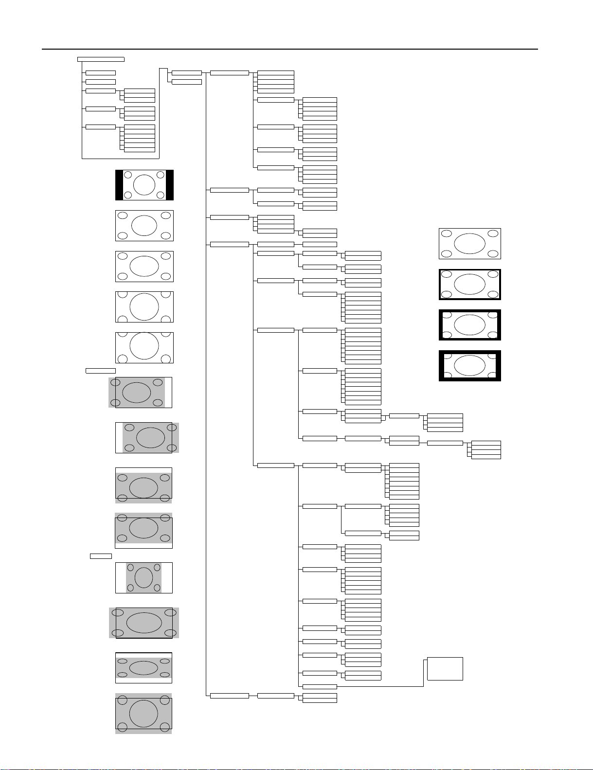
VIDEO MODE ADJUSTMENTVIDEO MODE ADJUSTMENTVIDEO MODE ADJUSTMENTVIDEO MODE ADJUSTMENT
POWER ON
MENU
PICTURE
Contrast
Brightness
POWER OFF
ENTER
Color
Tint
RGB
RGB 1
Sharpness
RGB 2
RGB 3
Picture Mode
Dynamic
Fine
VIDEO
Video
Real 1
S-Video
Real 2
Comp. Video
Static
WIDE
Normal
Color Temp.
Standard
Auto
Cool
Wide 1
User
Wide 2
Warm
Zoom 1
Zoom 2
User Color Temp.
Red
{0 to 255}
Green
{0 to 255}
Blue
{0 to 255}
Normal
Noise Reduction
Std
Max
Off
Min
POSITION/SIZE
Position
Horizontal
{-30 to +30 (Comp. Video -16 to +16) (1080I,720P -32 to +32)}
Vertical
{-7 to +7 (Zoom:-15 to +15) (Comp. Video -16 to +16) (1080I,720P -32 to +32)}
Size
Width
{-7 to +7 (Comp. Video -4 to +4)}
Wide 1
Height
{-7 to +7 (Comp. Video -4 to +4)}
AUDIO
Treble
{-6 to +6}
Bass
{-6 to +6}
Balance
{-10 to +10}
Mask Off
Loudness
On
Off
FEATURES
Adjustment
Clamp Position
{-8 to +8} *Only Comp. Video
Wide 2
Function
24 Frame model
On
Off
3D Y/COnMask 5
Off
On Screen Menu
OSD
On
Off
Language
English
Deutsch
Espanol
Francais
Mask 10
Italiano
Portugues
Pycc
*Only E-model
Input Terminal
Video Input
Auto
NTSC
PAL
SECAM
PAL 60
Mask 15
N-PAL
M-PAL
4.43 NTSC
Position
Horizontal "-"
S-Video Input
Auto
NTSC
PAL
SECAM
PAL 60
N-PAL
M-PAL
4.43 NTSC
BNC Input
RGB PC
Horizontal "+"
Decoder
Mask
Off
Comp.video
5
10
15
D-SUB Input
Function
RGB PC
Decoder
Mask
Off
5
1015Vertical "-"
Others
Picture Memory
Load
Memory 1
Save
Memory 2
Memory 3
Memory 4
Memory 5
Memory 6
Memory 7
Memory 8
DPMS
Time
Off
Vertical "+"
1 min
15 min
45 min
60 min
Background
Black
White
Audio Input
No Audio
Audio 1
Size
Width "-"
Audio 2
Audio 3
Input Priority
Off
RGB2
RGB3
Video
S-Video
Comp. Video
Width "+"
Monitor No.
0
1
234
White Screen
OffOnExhibition Mode
Off
Height "-"
On
Installation
Normal
+90 Deg
Mode
-90 Deg
Monitor No.
Freq. Scan Mode
Key Lock
Off
Input Signal
On
Freq.
Information
Height "+"
FACTORY DEFAULT
Execute
Yes
No
{-30 to +30 (Comp. Video -60 to +60)}
{-16 to +16}
REMOTE CONTROLLER
{-30 to +30}
{-60 to +60}
{-60 to +60}
Zoom 1
Zoom 2
кий
- 10 -
Page 3
- 12 -
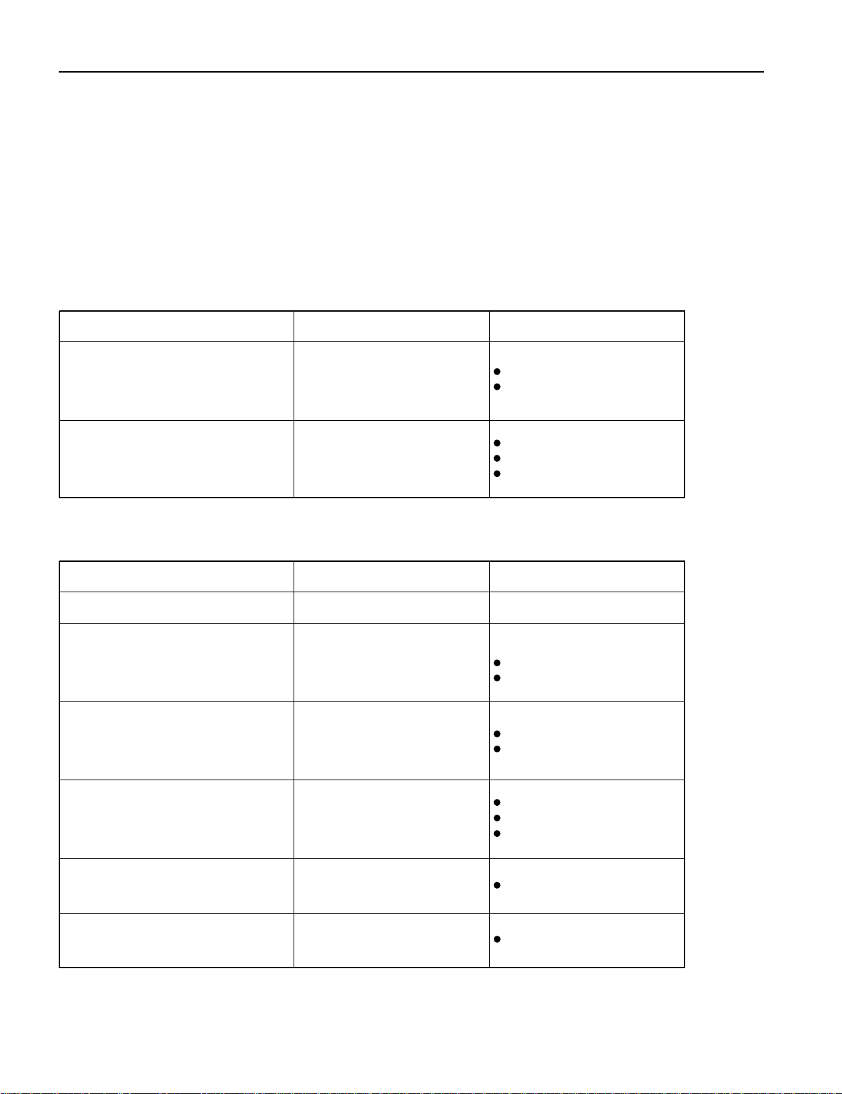
TROUBLESHOOTING USING LED AND OSD
1. Display
(1) OSD
Two kinds of error messages are displayed on the screen, and the power is turned off 10 sec later.
(2) LED
LED error is displayed continuously after the power is turned off.
2. Error types and check points
On screen display Cause Check point
ERROR MESSAGE CONDITION 1
Fan protector operated
Fan
Main/Digital PCB
ERROR MESSAGE CONDITION 2
Temperature protector
operated
Ambient temperature of unit
Main/Digital PCB
Temp. sensor IC757
(1) OSD
LED lamp display status Cause Check point
Steady light (Red)
Stand-by status
Continuous
Flashes continuously (Red)
No power
Power supply protector
operated
1 time
Flashes once every 4 sec. (Red)
Fan protector operated
Fan
Main/Digital PCB
Main/Digital PCB
2 times
Flashes twice every 5 sec. (Red)
Temperature protector
operated
Ambient temperature of unit
Temperature sensor IC757
Main/Digital PCB
4 times
Flashes four times every 7 sec.
(Red)
Main/Digital circuit faulty Main/Digital PCB
5 times
Flashes five times every 8 sec.
(Red)
Video circuit faulty Video PCB Assy
(2) LED
--------------------
PDP panel
- 12 -
Page 4

MAIN POWER SELECTOR SWITCH ADJUSTMENT
Adjustment
Note:
Confirm the main voltage set switch is set to 230V. (W and E version)
Confirm the main voltage set switch is set to 110V. (U version)
230V covers input AC voltage from 200V till 260V, and 110V covers from
90V till 130V.
- 19 -
Page 5

EXPLANATION OF LABELS
Panel Label Information
MC106W36P4
No.
Vbk : Vsus :
Ve : Vad
MADE IN JAPAN
Panel Production Date
Panel Production Date
For Example---------1.8.2
18 2
Year Month
9 : 1999 1 : JAN 1 : Beginning of Month(01-10th)
0 : 2000 2 : FEB 2 : Middle of Month (11-20th)
1 : 2001 3 : MAR 3 : End of Month (21-31st)
2 : 2002
9 : SEP
0 : OCT
N : NOV
D : DEC
For Example----------- YA1450001
YA 1 4 5 0001 * MID/AUG/2001
* YA Production Line
1 Production Line No. 4 Production Period (Day)
1st Month
2 Production Year 1 : BEG (1-10)
1 : 2001 2 : MID (11-20)
2 : 2002 3 : END (21-30/31)
2nd Month
3 Production Month 4 : BEG (1-10)
1 : JAN-FEB 5 : MID (11-20)
2 : MAR-APR 6 : END (21-30/31)
3 : MAY-JUN
4 : JLY-AUG 5 Serial Number
5 : SEP-OCT From 0001----6 : NOV-DEC
1
2
3
4
5
* * *
.
.
*****
V
*****
V
:
*****
V
*****
V
**********
1
2
3
4
5
Unit Serial Number
Panel Part Number
Panel Serial Number
Adjustment Voltage
- 20 -
Page 6
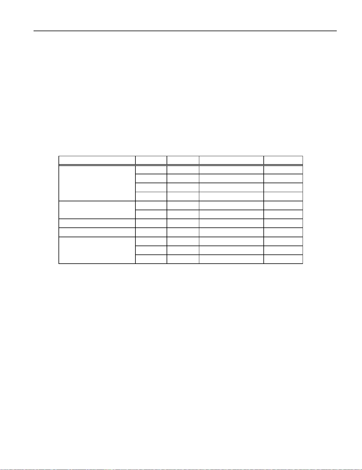
REPLACEMENT PARTS AND REQUIRED ADJUSTMENT
Caution
Preparation
Quick adjustment after PCB replacement
To remove PCB, wait for 1 minute after power was turned off for electrolytic capacitors to discharge.
Wide------------------ Auto
Input------------------ White pattern
PCB Item VR Test Point Level
Vsus R639 TPVsus Vsus ± 1V
Vbk R513 TPVBK 140V ± 5V
Vda R528 P27 connector pin 2 75V ± 0.5V
PFC R548 P4 connector pin 1 400V ± 1V
Vset R6940 TPSET 224V ± 1V
Vad R960 TPVAD VAD ± 1V
Sustain Drive PCB Ve R6829 TPVE VE ± 1V
Panel Drive Power PCB Vad R960 TPVAD VAD ± 1V
Vsus R639 TPVsus Vsus ± 1V
Vad R960 TPVAD VAD ± 1V
Ve R6829 TPVE VE ± 1V
Panel Glass
Scan Drive PCB
Power Supply PCB
- 21 -
Page 7

R6490/Vset
R639/Vsus R528/Vda R513/Vbk R960/Vad
R6556 R6524
S701
110V/230V Switch
R548/PFC R6829/Ve
TPSC1
R6524
TPSC2
TPVAD TPSS1 TPVe TPSS1
TPVscn TPVset TPVsus TPVbk
Label (Panel Information)
Label (Serial Number for Unit)
TPPR1 TP15V TPSS1
Adjustment VR Location
Test Point Location
VR AND TEST POINT LOCATION
- 22 -
Page 8
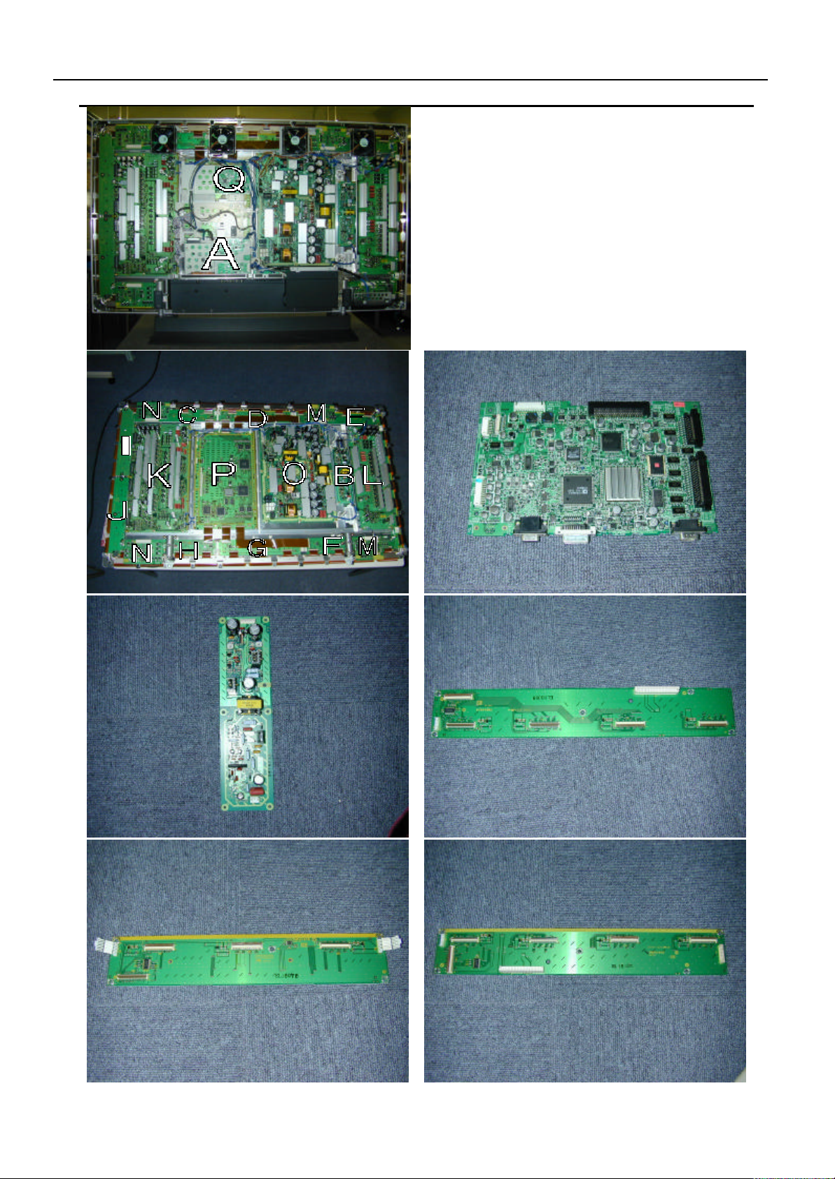
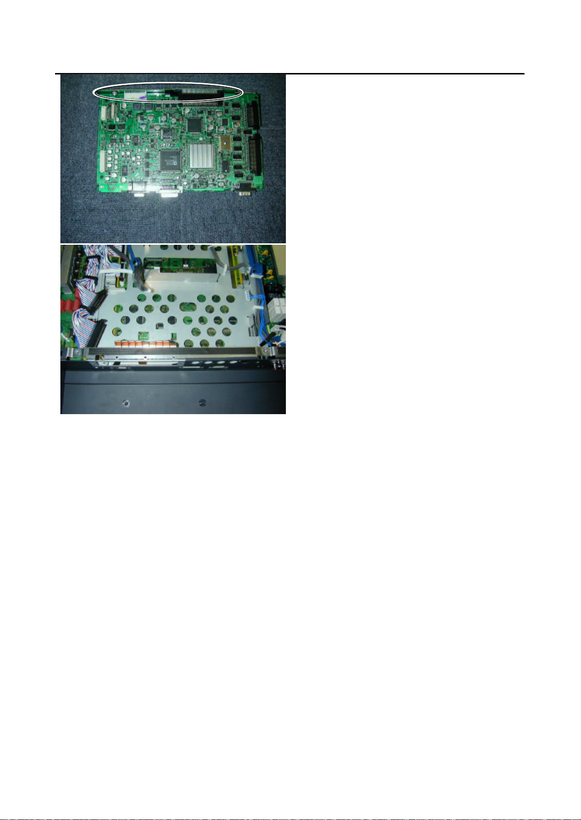
A: Main Digital PCB
Left) PCB
Center) PCB
Right) PCB
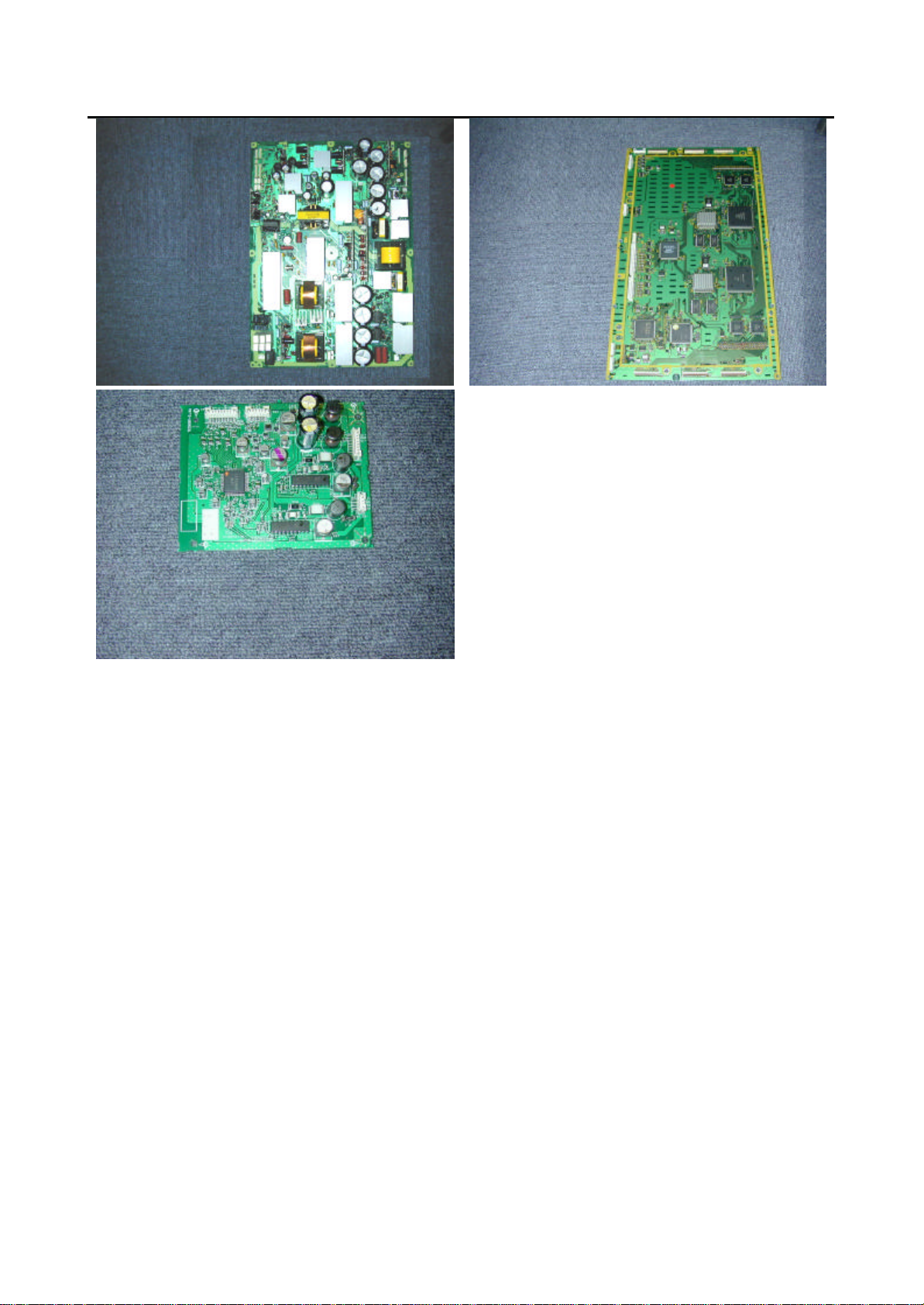
DISASSEMBLY PROCEDURES
1.Layout of Main PCB
1) Layout of Main PCB.
B: Panel
Drive
Power
PCB
C: Data Drive (Upper
D: Data Drive (Upper
E: Data Drive (Upper
Page 9

PARTS LIST
Ref.no. Description PDS5003W-H PDS5003E-H PDS5003U-H PDS5003W-S PDS5003E-S PDS5003U-S
Packing Pad-Bottom 8112249003
Cabinet Case Front 8112221009 8112484008
Case Rear 8112437004
Electric Fan Motor 8900280003
Optical Filter 8113177008
Filter PCB Assy 8112791007 8112792004 8112791007 8112523004
Audio Connection PCB 8113113006
Audio Main PCB 8113083002
Connection PCB Assy 8113075007
DC/DC PCB Assy 8113081008
I/O PCB Assy 8113073003
Key Switch PCB Assy 8113079005
LED/PHOTO PCB Assy 8113077001
Main Digital PCB Assy 8113339000
Video PCB Assy 8113071009
PDP Unit S141010282
Power Cord VDE 8112527002 ----------- 8112527002 ---------- UL.CSA ----------- ----------- 8112528009 ----------- ----------- 8112528009
Remote Control Unit 8108442005 8110867001
Panel Glass S141010107
Panel Drive Power PCB (P4) S141009958
Data Drive (Upper Left) PCB (C1) S141009965
Data Drive (Upper Center) PCB (C2) S141009972
Data Drive (Upper Right) PCB (C3) S141009989
Data Drive (Lower Right) PCB (C4) S141009996
Data Drive (Lower Center) PCB (C5) S141010008
Data Drive (Lower Left) PCB (C6) S141010015
Scan Drive Output (Upper) PCB (SU) S141010022
Scan Drive Output (Lower) PCB (SD) S141010039
Scan Drive PCB (SC) S141010046
Sustain Drive PCB (SS) S141010053
Saving Power (Upper/Lower Right) PCB (C7) S141010060
Saving Power (Upper/Lower Left) PCB (C8) S141010077
Power Supply PCB (P1) S141010084
Digital Process and Control PCB (D) S141010091
Packing Carton Top 8112482004
Carton Bottom 8112247009
Packing Joint-D 8108655009
Packing Pad-Top 8112248006
: Same as left
Page 10
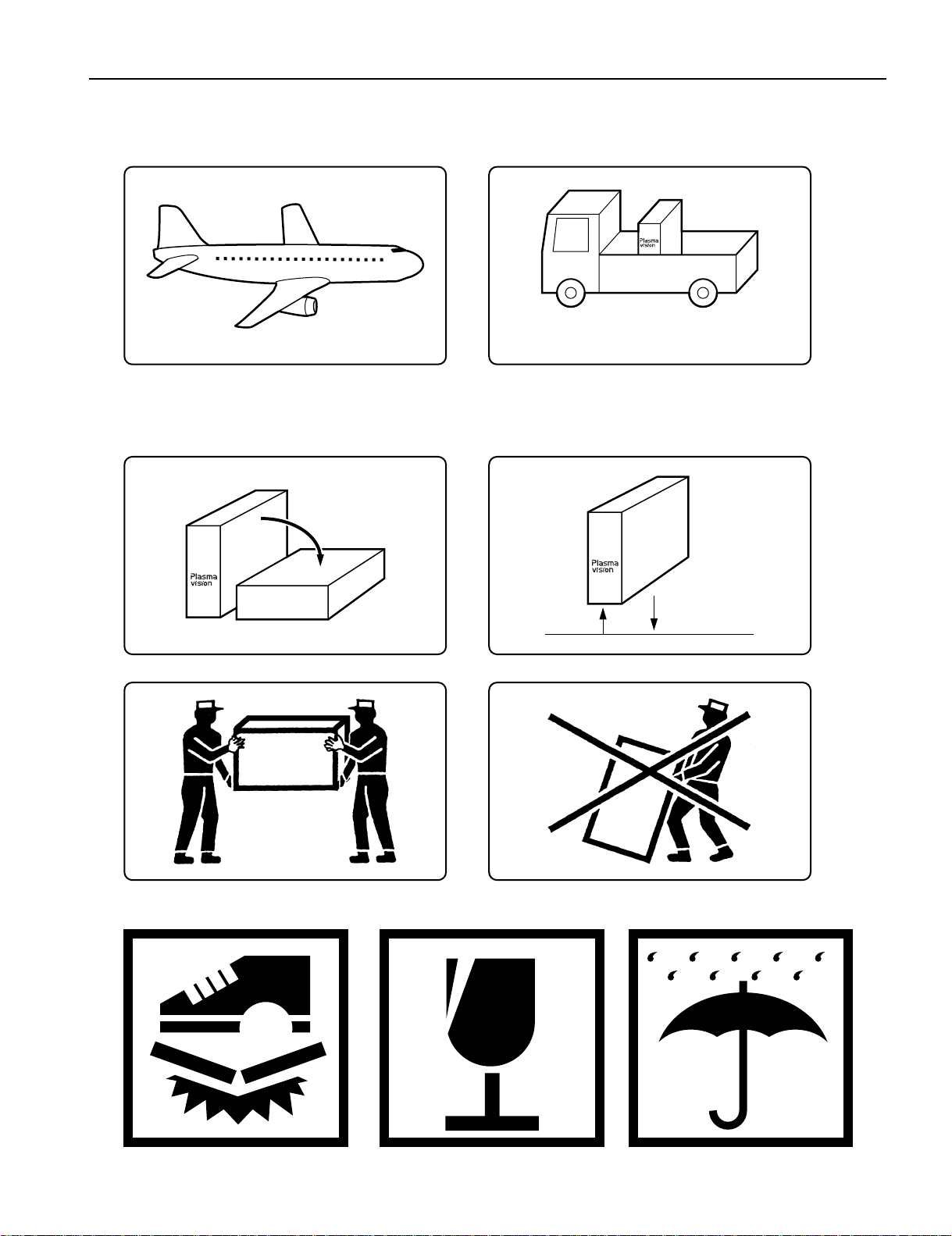
TRANSPORTATION AND HANDLING RESTRICTIONS
Transportation
Bad loading
Don't load the plasmavision on a truck
as shown in the drawing.
Handling
Never drop.Never topple.
Don't hold the
surface of the
optical filter.
Over 20 cm
Drop
Floor
- 60 -
Page 11
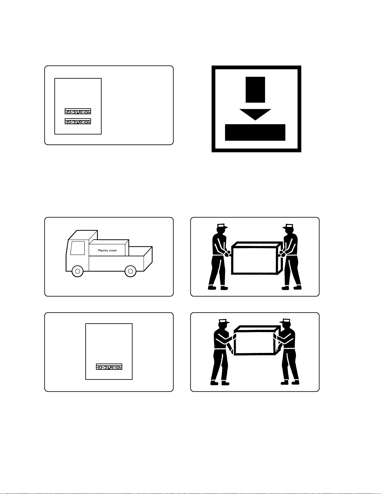
3
Don't stack the
plasmavision over
two units high.
Example of good transportation and handling
Good loading
Load the plasmavision as shown above.
2
- 61 -
Page 12

PARTS LIST
Ref.no. Description PDS5004W-S PDS5004E-S PDS5004U-S
Cabinet Case Front 8112484008
Case Rear 8112437004
Electric Fan Motor 8900280003
Optical Filter 8112399005
Filter PCB Assy 8112791007 8112792004
Audio Connection PCB 8113113006
Audio Main PCB 8113083002
Connection PCB Assy 8113113006
DC/DC PCB Assy 8113081008
I/O PCB Assy 8113073003
Key Switch PCB Assy 8113079005
LED/PHOTO PCB Assy 8113077001
Main Digital PCB Assy 8113339000
Video PCB Assy 8113071009
PDP Unit S141010282
Power Cord VDE 8112527002 -----------
UL.CSA ----------- ----------- 8112528009
Remote Control Unit 8110867001
Panel Glass S141010107
Panel Drive Power PCB (P4) S141009958
Data Drive (Upper Left) PCB (C1) S141009965
Data Drive (Upper Center) PCB (C2) S141009972
Data Drive (Upper Right) PCB (C3) S141009989
Data Drive (Lower Right) PCB (C4) S141009996
Data Drive (Lower Center) PCB (C5) S141010008
Data Drive (Lower Left) PCB (C6) S141010015
Scan Drive Output (Upper) PCB (SU) S141010022
Scan Drive Output (Lower) PCB (SD) S141010039
Scan Drive PCB (SC) S141010046
Sustain Drive PCB (SS) S141010053
Saving Power (Upper/Lower Right) PCB (C7) S141010060
Saving Power (Upper/Lower Left) PCB (C8) S141010077
Power Supply PCB (P1) S141010084
Digital Process and Control PCB (D) S141010091
Packing Carton Top 8112482004
Carton Bottom 8112247009
Packing Joint-D 8108655009
Packing Pad-Top 8112248006
Packing Pad-Bottom 8112249003
: Same as left
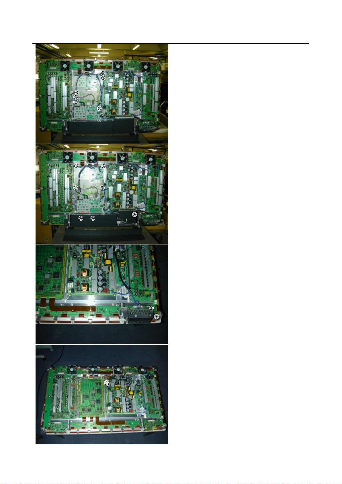
Page 13
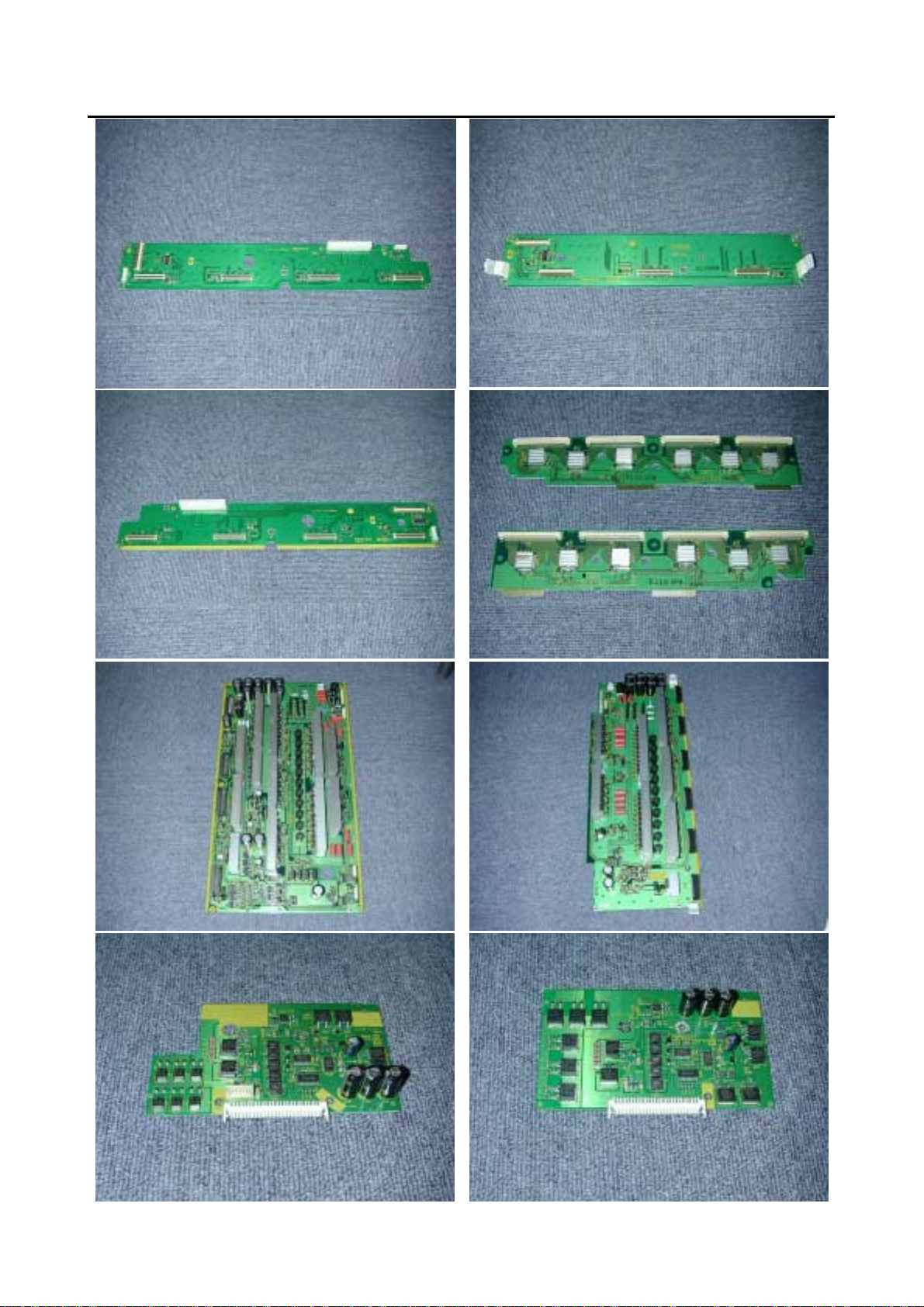
1.LayoutofMainPCB.(2of3)
F: Data Drive (Lower
Right) PCB
H: Data Drive (Lower
Left) PCB
K: Scan
Drive
G: Data Drive (Lower
Center) PCB
I: Scan Drive Output (Upper)
J: Scan Drive Output (Lower)
L: Sustain
Drive
PCB
M: Saving Power
(Upper/Lower Left)
PCB
N: Saving Power
(Upper/Lower Right)
Page 14
Main PCB
1. Layout of Main PCB (3 of 3)
O: Power
Supply
PCB
Q: Audio
P: Digital
Process
and
Control
Page 15

2. Removing the Video PCB
* The Video PCB can be removed without
moving the Rear Case.
1) Remove the 2 circled screws.
2) Pull out the Video PCB Unit from the
Plasmavision.
3) Remove 5 screws from the Video PCB Unit.
4) Remove the Video PCB Assy.
Page 16
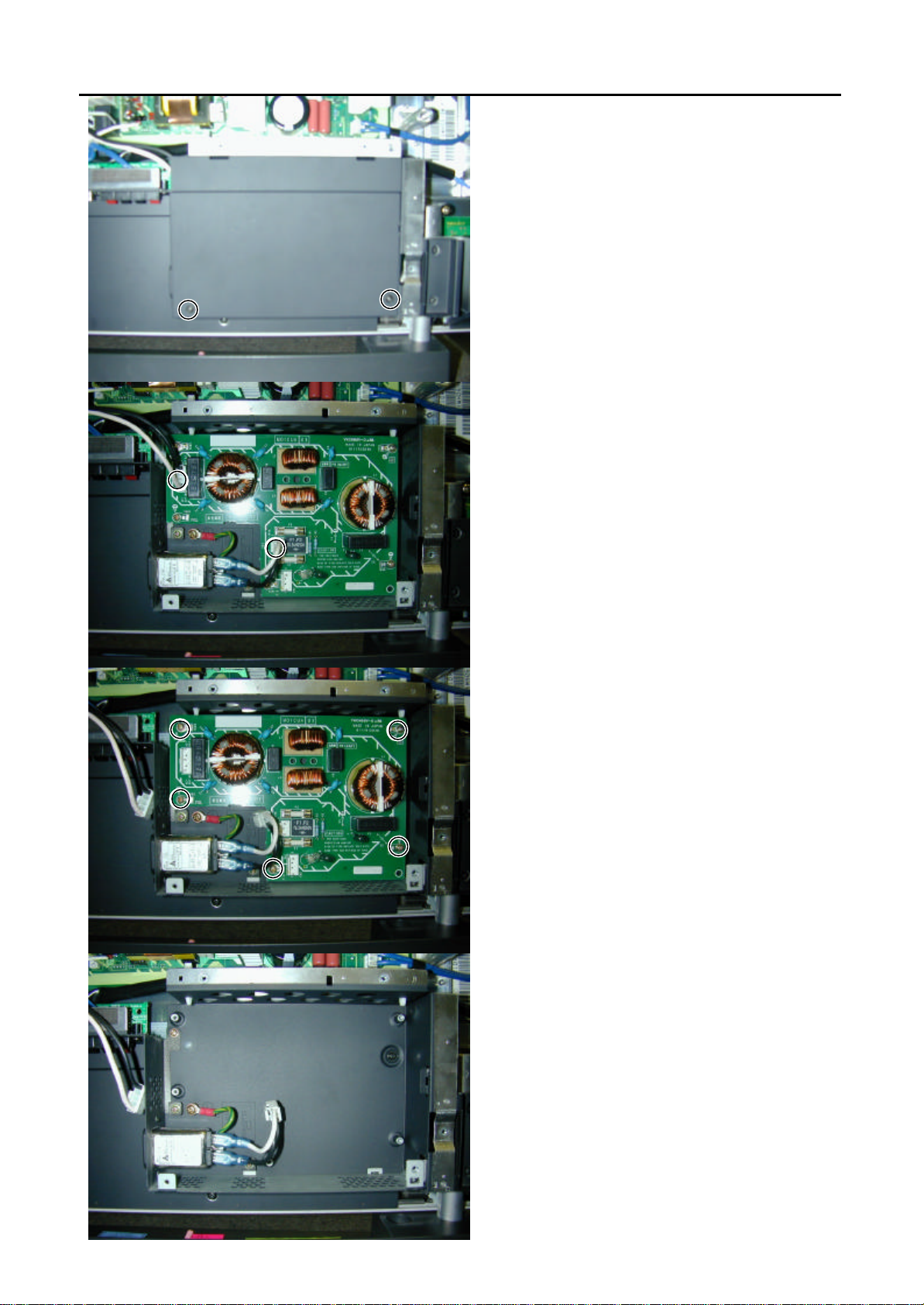
3. Removing the PFC PCB
1) Remove the Rear Case.
2) Remove the 2 screws and PFC cover.
3) Disconnect the circled connector.
4) Remove the 5 screws and PFC PCB.
* View after PFC PCB removed.
Page 17
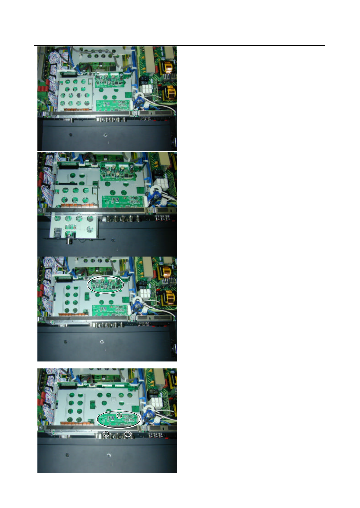
4. Removing the Main Digital PCB (1 of 3)
1) Remove the Rear Case.
2) Remove the Video Unit.
3) Remove the DC/DC PCB.
4) Remove the 3 screws and I/O PCB.
Page 18
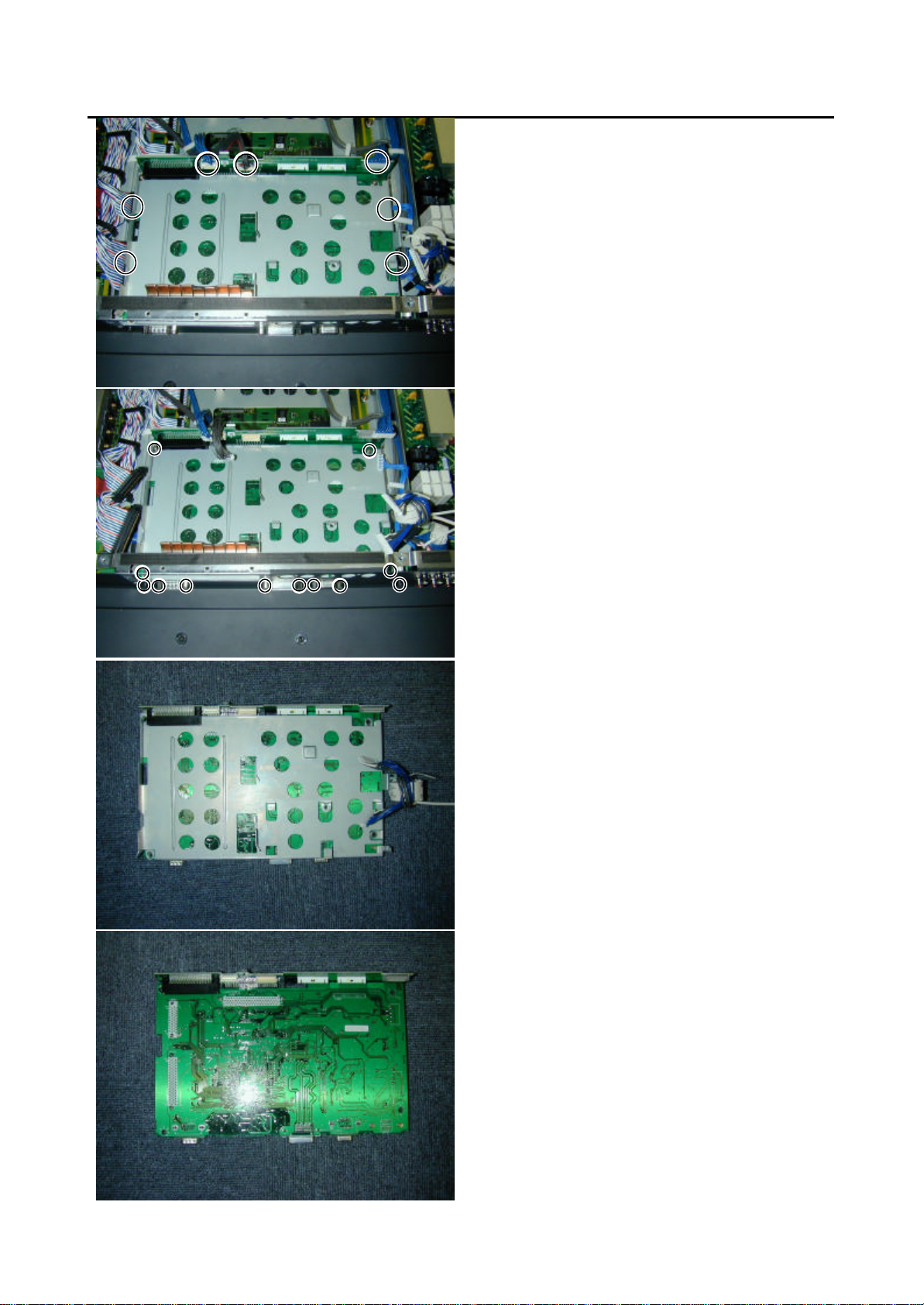
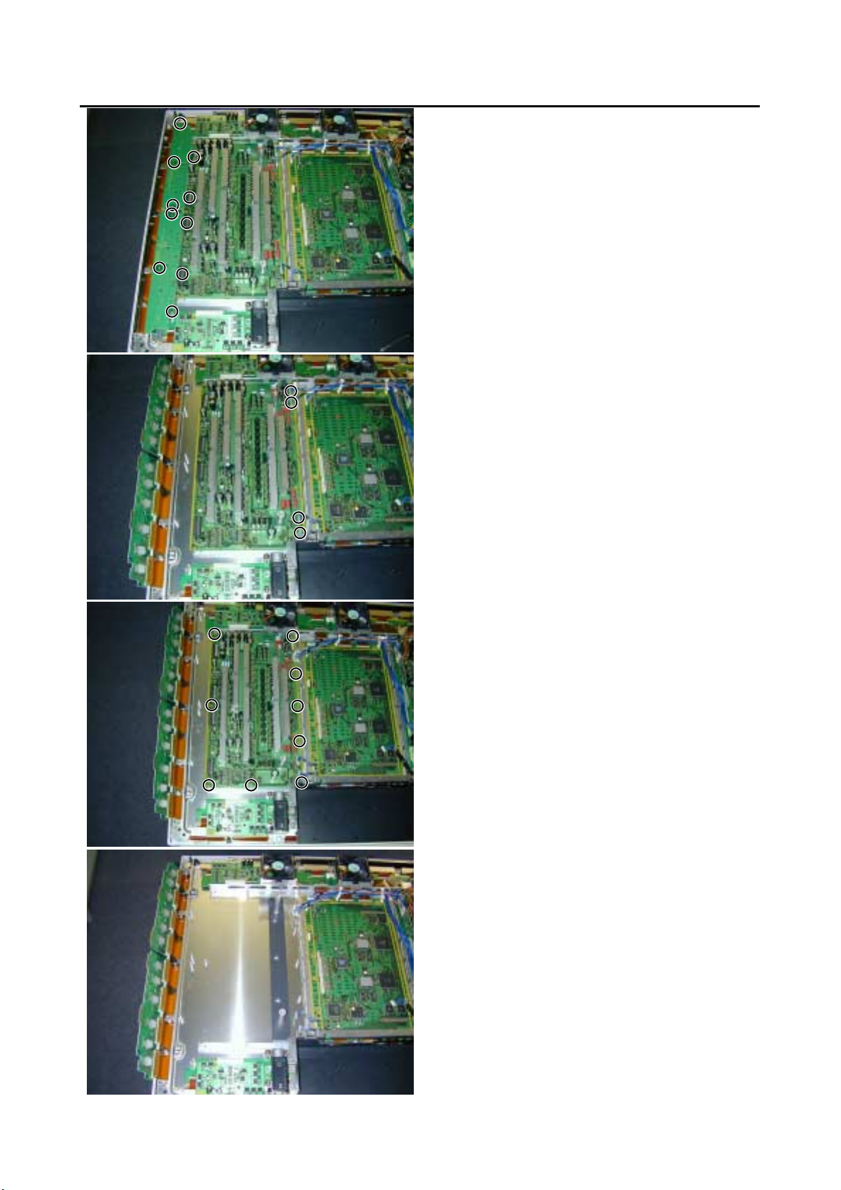
4. Removing the Main Digital PCB (2 of 3)
5) Disconnect the circled connector.
6) Remove the 12 screws and Main
Digital Unit.
7) Remove the shield.
8) Turn over the Main Digital PCB.
Page 19
4. Removing the Main Digital PCB (3 of 3)
9) Remove the Connection PCB.
* View after Main Digital PCB removed.
Page 20

5. Removing the PDP Unit (1 of 3)
1) Remove the 28 screws and Rear Case.
2) Remove the 5 screws and 2 connectors.
3) Remove the Panel and PCBs together from
Front Case.
(Lift the bottom of the Front Case.)
* View of removal of the Panel and PCBs from
the Front Case.
Page 21
5. Removing the PDP Unit (2 of 3)
4) Disconnect the circled connector.
5) Remove the PFC PCB.
6) Remove the 7 screws.
7) Remove the 2 screws.
8) Disconnect the circled connector.
Page 22

5. Removing the PDP Unit (3 of 3)
9) Remove the 4 fans.
10) Remove the 15 screws.
* View after only the PDP Unit removed.
* Replace the parts which are already mounted
correctly, when the PDP Unit is replace.
Page 23

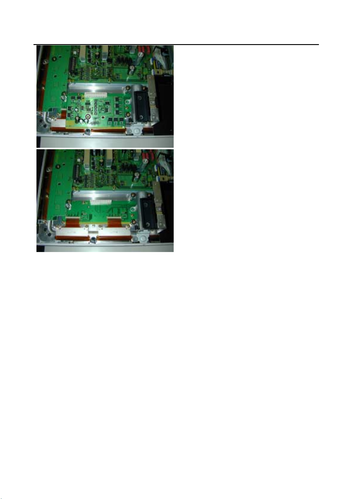
6. Removing the Audio PCB
1) Remove the circled connector.
2) Remove the 4 screws.
* View after Audio PCB removed.
Page 24

7. Removing the Panel Drive Power PCB
1) Remove the Rear Case.
2) Remove the circled connector.
3) Remove the 6 screws and Panel Drive
Power PCB.
* View after Panel Drive Power PCB removed.
Page 25

8. Removing the Data Drive (Upper Left) PCB
1) Remove the Rear Case.
2) Remove the Fan and Saving Power PCB.
3) Disconnect the circled connector.
4) Remove the 5 screws and Data Drive
(Upper Left) PCB.
* View after Data Drive (Upper Left) PCB
removed.
Page 26
9. Removing Data Drive (Upper Center) PCB
1) Remove the Rear Case.
2) Remove the Fan.
3) Disconnect the circled connector.
4) Remove the 5 screws and Data Drive
(Upper Center) PCB.
* View after Data Drive (Upper Center) PCB
removed.
Page 27

10. Removing the Data Drive (Upper Right) PCB
1) Remove the Rear Case.
2) Remove the Saving Power PCB.
3) Remove the circled connector.
4) Remove the 5 screws and Data Drive
(Upper Right) PCB.
* View after Data Drive (Upper Right) PCB
removed.
Page 28

11. Removing the Data Drive (Lower Right) PCB (1 of 3)
1) Remove the Rear Case.
2) Remove the PFC PCB.
3) Disconnect the circled connector.
4) Remove the 8 screws.
5) Remove the 2 screws.
Page 29

11. Removing the Data Drive (Lower Right) PCB (2 of 3)
6) Remove the circled connector.
7) Remove the 1 screw and Saving Power PCB.
8) Remove the 4 screws and stand support
9) Remove the circled connector.
Page 30

11. Removing the Data Drive (Lower Right) PCB (3 of 3)
10) Remove the 5 screws and Data Drive
(Lower Right) PCB.
* View after Data Drive (Lower Right) PCB
removed.
Page 31

12. Removing the Data Drive (Lower Center) PCB (1 of 2)
1) Remove the Rear Case.
2) Remove the PFC PCB.
3) Disconnect the circled connector.
4) Remove the 10 screws.
5) Disconnect the circled connector.
Page 32
12. Removing the Data Drive (Lower Center) PCB (2 of 2)
6) Remove the 5 screws and Data Drive
(Lower Center) PCB.
* View after Data Drive (Lower Center) PCB
removed.
Page 33

13. Removing the Data Drive (Lower Left) PCB (1 of 2)
1) Remove the Rear Case.
2) Remove the PFC PCB
3) Disconnect the circled connector.
4) Remove the 10 screws and Saving Power
PCB.
5) Remove the 4 screws and stand support.
Page 34

13. Removing the Data Drive (Lower Left) PCB (2 of 2)
6) Disconnect the circled connector.
7) Remove the 5 screws and Data Drive (Lower
Left) PCB.
* View after Data Drive (Lower Left) PCB
removed.
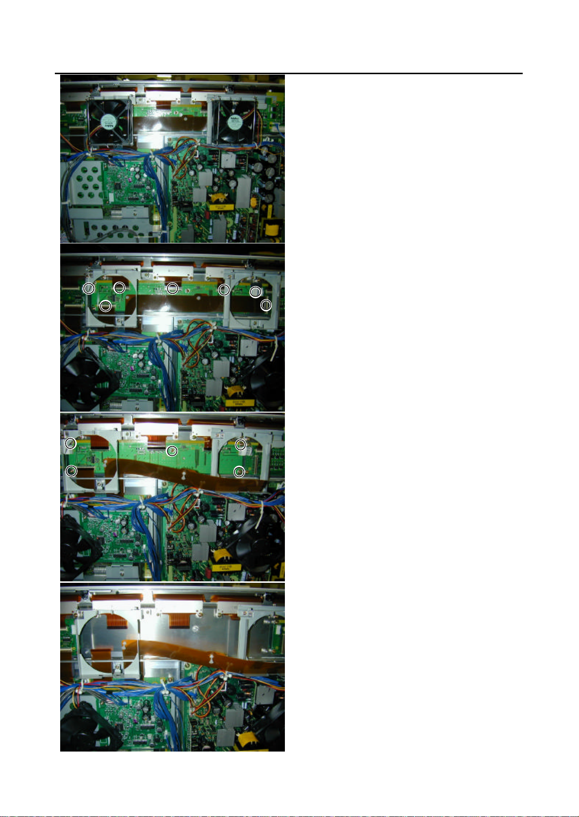
Page 35

14. Removing the Scan Drive Output (Upper / Lower)
1) Remove the Rear Case.
2) Remove the 6 screws.
3) Disconnect the circled connector.
4) Disconnect the circled connector.
* View after Scan Drive Output (Upper/Lower)
PCB removed.
Page 36

15. Removing the Scan Drive PCB (1 of 2)
1) Remove the Rear Case.
2) Remove the Video Unit.
3) Disconnect the circled connector.
4) Remove the 14 screws and Shield Frame.
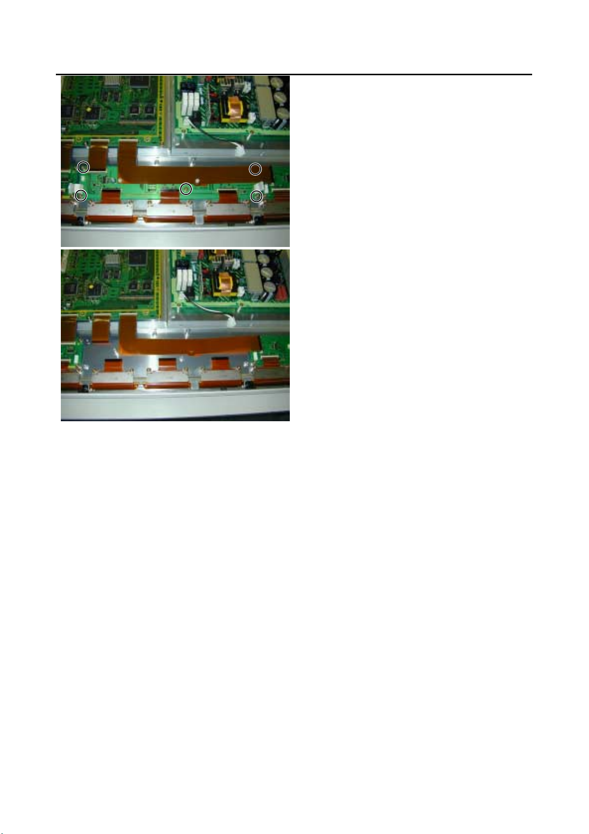
Page 37
15. Removing the Scan Drive PCB (2 of 2)
5) Remove the 6 screws and circled connector.
6) Remove the circled connector.
7) Remove the 9 screws and Scan Drive PCB.
* View after Scan Drive PCB.
Page 38

16. Removing the Sustain Drive PCB
1) Remove the Rear Case.
2) Remove the circled connector.
3) Remove the 6 screws and Sustain Drive
PCB.
* View after Sustain Drive PCB removed.
Page 39

17. Removing the Saving Power (Upper Right) PCB
1) Remove the Rear Case.
2) Remove the Fan and circled connector.
3) Remove the 6 screws and Fan plinth.
4) Remove the 1 screws and Saving Power
(Upper Right) PCB.
* View after Saving Power (Upper Right) PCB
removed.
Page 40

18. Removing the Saving Power (Lower Right) PCB
1) Remove the Rear Case.
2) Remove the 2 screws.
3) Remove the circled connector.
4) Remove the 1 screw and Saving Power
(Lower Right) PCB.
* View after Saving Power (Lower Right) PCB
removed.
Page 41

19. Removing the Saving Power (Upper Left) PCB
1) Remove the Rear Case.
2) Remove the 1 screw and Saving Power
* View after Saving Power (Upper Left) PCB
removed.
(Upper Left) PCB.
Page 42
20. Removing the Saving Power (Lower Left) PCB
1) Remove the Rear Case.
2) Remove the 1 screw and Saving Power
* View after Saving Power (Lower Left) PCB
removed.
(Lower Left) PCB.
Page 43

21. Removing the Power Supply PCB (1 of 2)
1) Remove the Rear Case.
2) Remove the Fan.
3) Remove the 3 screws.
4) Disconnect the circled connector.
5) Remove the 9 screws and Power Supply
PCB.
Page 44
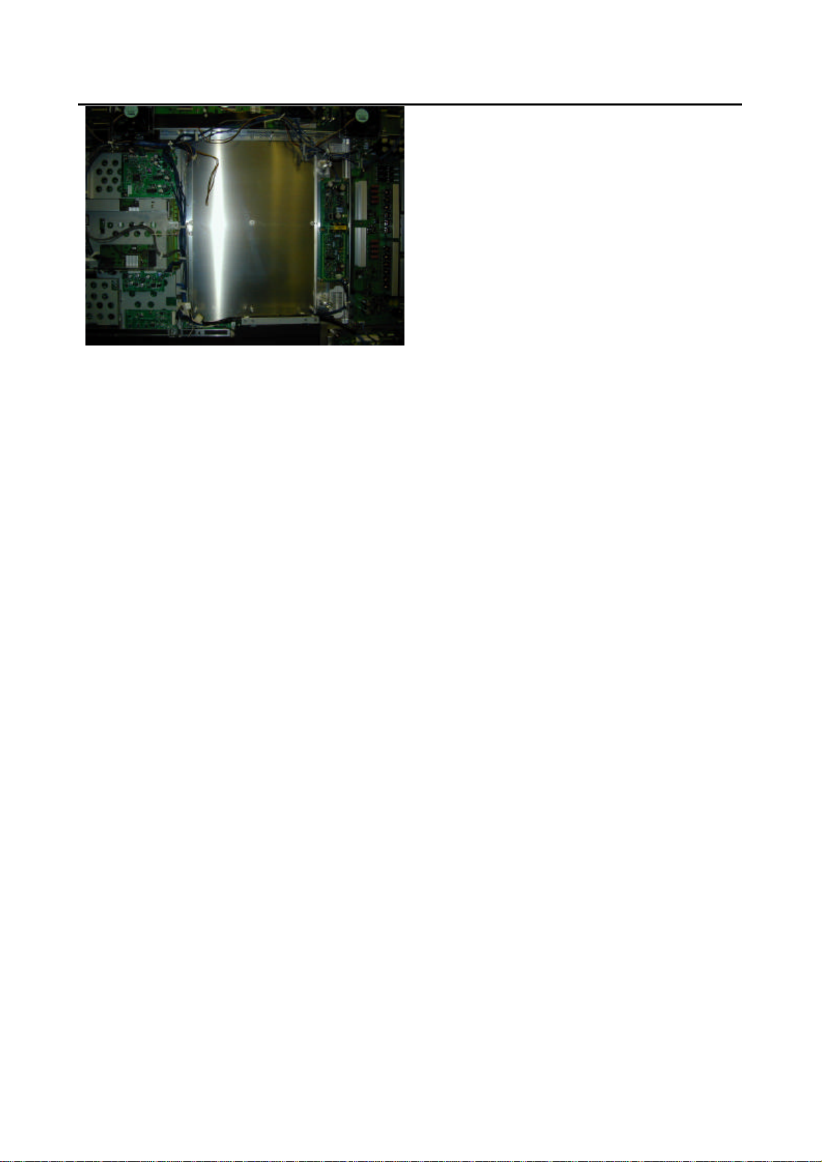
21. Removing the Power Supply PCB (2 of 2)
* View after Power Supply PCB.
Page 45

22. Removing the Digital Process and Control PCB (1 of 2)
1) Remove the Rear Case.
2) Remove the Video Unit.
3) Disconnect the circled connector.
4) Remove the 14 screws and Shield Frame.
Page 46
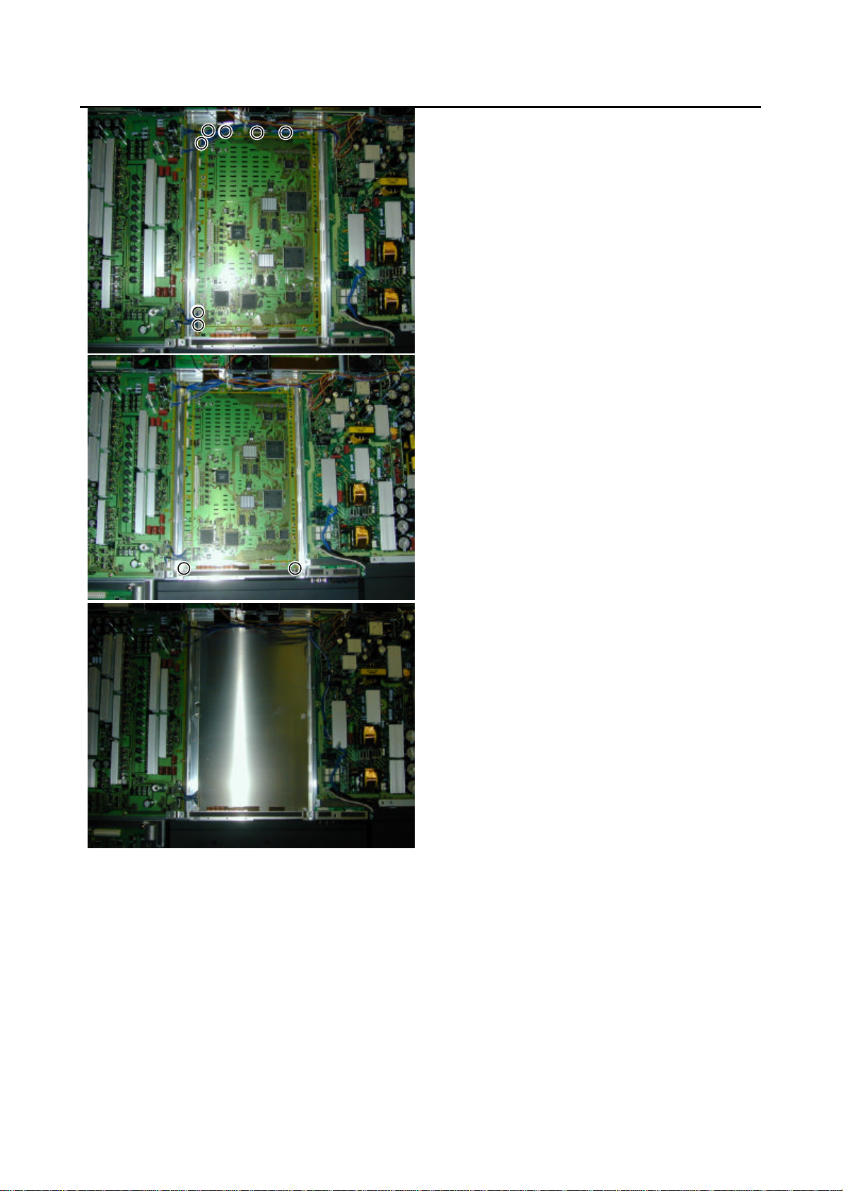
22. Removing the Digital Process and Control PCB (2 of 2)
5) Disconnect the circled connector.
6) Remove the 2 screws and Digital Process
and Control PCB.
* View after Digital Process and Control PCB.
Page 47

- 13 -
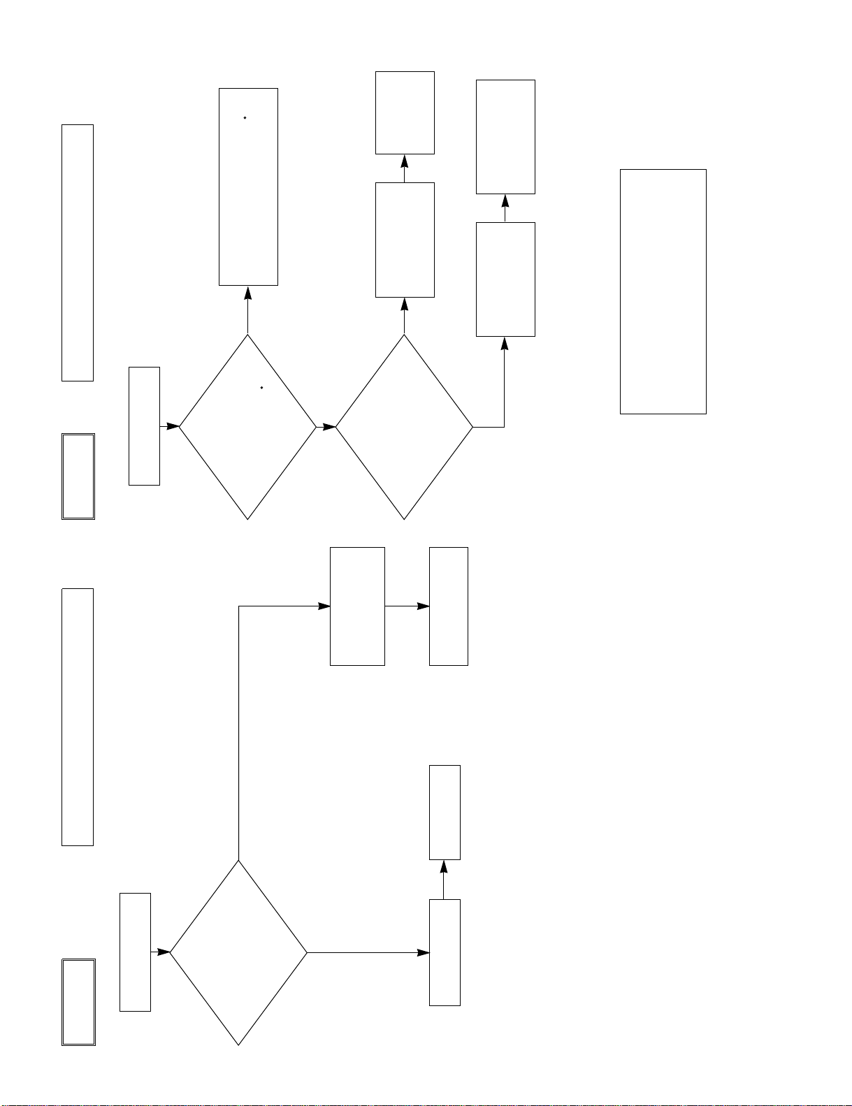
TROUBLESHOOTING FLOWCHART
LED lamp blinking
Turn power on and check
state of lamp.
Not lighted.
LAMP STATE
Blinks
continuously.
Power turned off
immediately.
RED
Blinks continuously.
Power turned off
immediately.
Power Supply
PCB faulty.
Check PDP Panel.
Check PDP Panel.
RED
Blinks once
Power turned off
after 10 sec.
RED
Check 1
Blinks twice
Power turned off
after 10 sec.
RED
Check 2
Blinks four times
Power not turned
off, LED blinks only.
RED
Replace Main/Digital
PCB Assy.
Blinks five times
Power not turned
off, LED blinks only.
RED
Replace Video PCB
Assy.
Is on-screen display
normal?
All input image
faulty.
Signal processing
Video PCB faulty.
Video PCB faulty.
PCB faulty.
Signal processing
PCB faulty.
Replace Main/Digital
PCB Assy.
Replace Main/Digital
PCB Assy.
Replace Video PCB
Assy.
Replace Video PCB
Assy.
Video input image
faulty.
Check PDP Panel.
S-video input image
faulty.
Component video
input image faulty.
RGB 1,2 input image
faulty.
Lights steadily for
more than 10 sec.
GREEN
NO
YES
Check 3
- 13 -
Page 48
No
No
Fan protector operated
Power lamp: Flashes once intermittently in red.
(For 0.5 sec. at an interval of 3 sec.)
Check 1
Start
Yes
Is voltage at
connectors P951 3pin,
P953 3pin and P954 3pin
on Main/Digital PCB
14V?
Microcomputer
peripheral
circuit faulty.
∗Replace Main/
Digital PCB Assy.
Temperature protector operated
Power lamp : Flashes intermittently twice in red.
(For 0.5 sec. at an interval of 5 sec.)
Check 2
Start
Adjust PDP unit installation so that
peripheral temperature is 40.0 C or
less.
No
Yes
Is ambient temperature
of IC757 on Main/Digital
PCB less than 60 C ?
Microcomputer
peripheral circuit
faulty.
Yes
Replace
Main/Digital
PCB Assy.
Fan faulty Replace fan.
Temperature
sensor IC757 faulty.
Temperature sensor cooling
The temperature sensor IC757 is installed
on Main/Digital PCB. Turn the power off
and cool with a point cooler.
Replace
temperature sensor
IC757.
Does unit
operate normally
when temperature sensor
IC757 changed ?
- 14 -
Page 49

Is Sync.
correctly ?
signal input to pin
le ?
Is frequency of horizontal sync.
and vertical sync signals within
specified range ?
Is input level(∗) within specified
range ?
Signal processing circuit faulty.
Replace Main/Digital PCB Assy.
Is Sync. switch
signal input to pin 13 and vertical sync
Is frequency of horizontal sync.
and vertical sync signals within
specified range ?
Is input level(∗) within specified
range ?
.
.
No
Check input signal.
No
Check input signal.
Is frequency of horizontal sync.
and vertical sync signals within
specified range ?
Is input level(∗) within specified
range ?
.
.
RGB input is abnormal.
Power lamp: Lighted green
(10 sec or more)
Start
Separate signal Composite signal
No
Yes
Yes
Yes
Sync. on green signal
Yes
Yes
No
No
No
Is RGB
cable pin arrangement
appropriate ?
What kind of
signal is output from signal
source ?
Is composite sync.
signal input to pin 2 of RGB
cable ?
Is composite sync.
signal input to pin 13 of RGB
cable ?
(TLL/ANALOG) selected
Is horizontal sync.
signal input to pin 14 of
RGB cab
Check connection cable.
Check input signal.
Connect RGB cable
to terminal.
Check input signal.
No
Mak
Change sync.switch (TTL/ANALOG)
e sync. signal polarity output
from signal source negative, or make
output impedance TTL.
∗
Yes
.
.
Is Sync.
signal polarity
negative ?
Note(∗): If the synchronizing signal cannot be identified by
TTL level, it is in the 75Ω terminated state.
Yes (ANALOG)
Yes
Check 3
- 15 -
Page 50
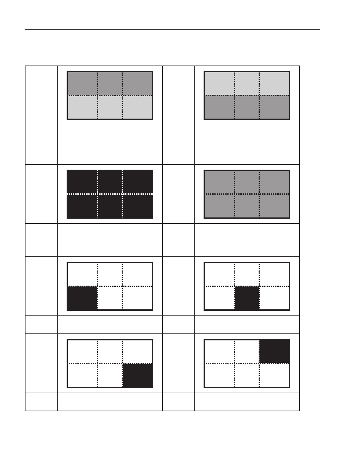
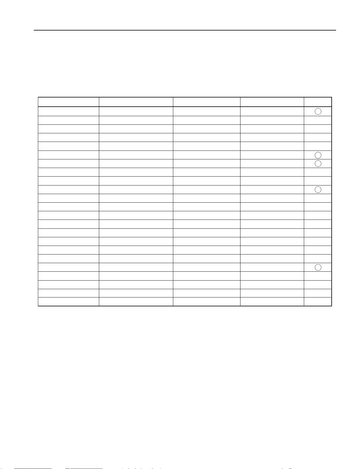
TROUBLESHOOTING PANEL
The plasma display panel consists of a set of six surfaces and is connected to each PCB.
For that reason, the faulty part of PCB or plasma display panel can be focused depending on its symptom.
Symptom
1. Digital Process and Control (D)
Check
PCB
Symptom Symptom
Check
PCB
2. Data Drive Power (U/L) (C1)
3. Data Drive Power (U/C) (C2)
4. Data Drive Power (U/R) (C3)
5. Sustain Drive (SS)
1. Main/Digital PCB
2. Digital Process and Control (D)
3. Scan Drive (SC)
4. Sustain Drive (SS)
Symptom
Check
PCB
Check
PCB
1. Digital Process and Control (D)
2. Data Drive Power (L/R) (C4)
3. Data Drive Power (L/C) (C5)
4. Data Drive Power (L/L) (C6)
5. Sustain Drive (SS)
1. Digital Process and Control (D)
2. Sustain Drive (SS)
Symptom Symptom
Check
PCB
Symptom Symptom
Check
PCB
1. Digital Process and Control (D)
2. Data Drive Power (L/R) (C4)
1. Digital Process and Control (D)
2. Data Drive Power (L/L) (C6)
Check
PCB
Check
PCB
- 16 -
1. Digital Process and Control (D)
2. Data Drive Power (L/C) (C5)
1. Digital Process and Control (D)
2. Data Drive Power (U/L) (C1)
Page 51

Symptom Symptom
Check
PCB
1. Digital Process and Control (D)
2. Data Drive Power (U/C) (C2)
Check
PCB
Symptom Symptom
Check
PCB
1. Saving Power (C7) 1. Saving Power (C8)
Check
PCB
Symptom Symptom
Check
PCB
1. Scan Drive Output (Upper) (SU)
2. Scan Drive (SC)
Check
PCB
1. Digital Process and Control (D)
2. Data Drive Power (U/R) (C3)
1. Scan Drive Output (Lower) (SD)
2. Scan Drive (SC)
Symptom Symptom
Check
PCB
1. Scan Drive Output (Upper) (SU)
2. Display Panel Assy (Glass)
Check
PCB
Symptom Symptom
Check
PCB
1. Data Drive Power (U/R) (C3)
2. Digital Process and Control (D)
3. Display Panel Assy (Glass)
- 17 -
Check
PCB
1. Scan Drive Output (Lower) (SD)
2. Display Panel Assy (Glass)
1. Data Drive Power (U/C) (C2)
2. Digital Process and Control (D)
3. Display Panel Assy (Glass)
Page 52

Symptom Symptom
Check
PCB
1. Data Drive Power (U/L) (C1)
2. Digital Process and Control (D)
3. Display Panel Assy (Glass)
Check
PCB
Symptom Symptom
Check
PCB
1. Data Drive Power (L/C) (C5)
2. Digital Process and Control (D)
3. Display Panel Assy (Glass)
Check
PCB
Symptom Symptom
Check
PCB
1. Sustain Drive (SS) 1. Display Panel Assy (Glass)
Check
PCB
1. Data Drive Power (L/R) (C4)
2. Digital Process and Control (D)
3. Display Panel Assy (Glass)
1. Data Drive Power (L/L) (C6)
2. Digital Process and Control (D)
3. Display Panel Assy (Glass)
- 18 -
Page 53

RGB MODE ADJUSTMENTRGB MODE ADJUSTMENTRGB MODE ADJUSTMENTRGB MODE ADJUSTMENT
POWER ON
MENU
PICTURE
Contrast
Brightness
POWER OFF
ENTER
Color
Tint
RGB
RGB 1
Sharpness
RGB 2
RGB 3
Picture Mode
Dynamic
Fine
VIDEO
Video
Real 1
S-Video
Real 2
Comp. Video
Static
Color Temp.
Standard
WIDE
Normal
Cool
Wide
User
Zoom
Warm
User Color Temp.
Red
{0 to 255}
Green
{0 to 255}
Blue
{0 to 255}
POSITION/SIZE
Position
Horizontal
{-150 to +150(Decoder:-16 to +16) (1080I,720P:-32 to +32)}
Vertical
{-150 to +150(Decoder:-16 to +16) (1080I,720P:-32 to +32)}
Size
Width
{-25 to +50(Decoder:-4 to +4)}
Height
{-25 to +50(Decoder:-4 to +4)}
AUDIO
Treble
{-6 to +6}
Bass
{-6 to +6}
Balance
{-10 to +10}
Loudness
On
Off
FEATURES
Adjustment
Dot Clock
{-60 to +60}
Clock Phase
Auto
Mask Off
Manual
{1 to 32}
Vertical Sync.
{-1 to +1}
Clamp Position
{-8 to +8}
Auto Calibration
Execute
Yes
No
On Screen Menu
OSDOnMask 5
Off
Language
English
Deutsch
Espanol
Francais
Italiano
Portugues
Position
Pycc
*Only E-model
Mask 10
Input Terminal
Video Input
Auto
NTSC
PAL
SECAM
PAL 60
N-PAL
M-PAL
4.43 NTSC
Mask 15
S-Video Input
Auto
NTSC
PAL
SECAM
PAL 60
N-PAL
M-PAL
4.43 NTSC
BNC Input
RGB PC
Decoder
Mask
Off
Comp.video
5
10
15
D-SUB Input
Function
RGB PC
Mask
Off
Decoder
5
1015Others
Picture Memory
Load
Memory 1
Save
Memory 2
Memory 3
Memory 4
Memory 5
Memory 6
Moving Area Std. (10 dot)
Memory 7
Memory 8
Size
DPMS
Time
Off
1 min
15 min
45 min
60 min
Moving Area Max. (15 dot)
Background
Black
White
Audio Input
No Audio
Audio 1
Audio 2
Audio 3
Screen Orbiter
Mode/Time
Off
Moving Area Min. (5 dot)
Time
Mode
Moving Area
Std
Max
Min
Input Priority
Off
RGB 2
RGB 3
Video
S-Video
Comp. Video
Monitor No.
012
3
4
Direct Setting
Auto
VGA
WVGA
480P
XGA
WXGA
SXGA
SXGA+
Code Setting
Auto
Manual
{01 to 2A} *Hexadecimal
White Screen
Off
On
Exhibition Mode
OffOnInstallation
Normal
+90 Deg
Mode
-90 Deg
Monitor No.
Freq. Scan Mode
Key Lock
Off
Input Signal
On
Freq.
Preset No.
Information
FACTORY DEFAULT
Execute
Yes
No
REMOTE CONTROLLER
Normal
{-30 to +30}
{-60 to +60}
{-60 to +60}
{-60 to +60}
{-4 to +4(Decoder -16 to +16)}
Width "+"
Height "-"
Height "+"
Wide
POSITION/SIZE
Horizontal "-"
Horizontal "+"
Vertical "-"
Vertical "+"
Width "-"
Zoom
кий
- 11 -
Page 54

SPECIFICATIONS
Power requirement 100-240V, 50/60Hz
Current drain 2.7A (W,E Type) 5.5A (U Type)
Display panel
Screen size 110.6 (W) x 62.2 (H) [cm]
43.5 (W) x 24.5 (H) [inch]
Aspect ratio 16 : 9
Number of pixels 1,366 (H) x 768 (V) pixels
Pixel pitch 0.81mm x 0.81mm
Contrast ratio PDS5001/5002 3000 : 1 (typ.)
Brightness 500 cd/m
2
(typ.)
Viewing angle Max. 160 degrees
Input Terminals
Video input BNC connector
1.0VP-P /75Ω
S video input S terminal
Y signal:1.0VP-P /75Ω
C signal:0.286VP-P /75Ω
Component Three BNC terminals
video input Y : 1VP-P /75Ω
Pb /B-Y: 0.7VP-P /75Ω
Pr /R-Y: 0.7VP-P /75Ω
RGB 1 input
DVI-D terminal
RGB 2 input mD-sub:15pin (3 row type)
Video : 0.7V
P-P /75Ω
SYNC signal : TTL level
RGB 3 input BNC terminal x 5
R: 0.7VP-P/75Ω
G: 0.7VP-P/75Ω
B: 0.7VP-P/75Ω
H: TTL level or 0.3VP-P /75Ω
V: TTL level or 0.3VP-P /75Ω
User set mode 8 memories (each RGB1,2)
Display frequency Horizontal :15.63 to 80.0MHz
Vertical : 50.0 to 120Hz
Dot clock:50MHz Max
XGA 68MHz Max
RS-232C D-sub 9 pin terminal
Color system
NTSC/PAL/SECAM/N-PAL/M-PAL
/4.43NTSC/PAL60
Audio input 2 pin terminals(one system)
500mVrms/22kΩ
Effective max.
Level terminal 8W+8W (L/R), 6
output
Environment (Operating)
Temperature 0 to 40 C
Relative humidity 20 to 80%
Pressure 850 to 1,114 hPa
Accessories User's manual
Remote controller
Batteries (Type AA x 2)
Power cord
Ferrite core (2)
Options
Stand P-50TT01
Wall mounting unit
P-50WB01 installation angle
Horizontal 0 to 15
Vertical 0 to 5
Ceiling mounting unit P-50CT01 installation angle
Available 0 to 15
Standards
PDS5001W/E/U-H/SPDS5002W/E/U -S
UL,CSA
Safety:
UL1950 UL1950
CSA C22.2 No.950 CSA C22.2 No.950
EMC: FCC Part15 Class A FCC Part15 Class B
ICES-003 Class A ICES-003 Class B
CE
Safety: EN60950 1992
A1 1993
A2 1993
A3 1995
A4 1997
EMC : EN55022 A1/A2
Class A
EN61000-3-2, 1995
EN61000-3-3, 1995
EN55024 1998
EN61000-4-2, 1995
EN61000-4-3, 1996
EN61000-4-4, 1995
EN61000-4-5, 1995
EN61000-4-6, 1996
Ω
EN61000-4-8, 1993
EN61000-4-11,1994
EN60950 1992
A1 1993
A2 1993
A3 1995
A4 1997
EN55022 A1/A2
Class B
EN61000-3-2, 1995
EN61000-3-3, 1995
EN55024 1998
EN61000-4-2, 1995
EN61000-4-3, 1996
EN61000-4-4, 1995
EN61000-4-5, 1995
EN61000-4-6, 1996
EN61000-4-8, 1993
EN61000-4-11, 1994
Display colors
16.7 million (256 each for R.G.B.)
Dimensions Width : 121.2cm (47.7 inch)
Height: 72.6cm (28.6 inch)
Depth : 9.8 cm ( 3.9 inch)
Net weight 45.0kg
AS
Safety : IEC950 A1/A2/A3/A4 IEC950 A1/A2/A3/A4
EMC : AS/NZS 3548 AS/NZS 3548
- 4 -
Page 55
SETTING SIGNALS
This display can store parameter settings for eight additional signals for RGB.
To do this, select the desired signal and follow "RGB MODE ADJUSTMENT" in the manual to adjust the parameters.
When you finish, the settings will be automatically stored.
FACTORY SET SIGNALS (RGB MODE)
Main corresponding signals (RGB mode)
Display (dots x lines)
640 x 480 31.47 59.94 VGA
640 x 480 37.86 72.81 VGA 72 Hz
640 x 480 37.50 75.00 VGA 75 Hz
640 x 480 43.27 85.01 VGA 85 Hz
720 x 400 31.47 70.09 400 lines
800 x 600 37.88 60.32 SVGA 60 Hz
800 x 600 48.08 72.19 SVGA 72 Hz
800 x 600 46.88 75.00 SVGA 75 Hz
800 x 600 53.67 85.06 SVGA 85 Hz
1024 x 768 48.36 60.00 XGA 60 Hz
1024 x 768 56.48 70.07 XGA 70 Hz
1024 x 768 60.02 75.03 XGA 75 Hz
1280 x 1024 63.98 60.02 SXGA 60 Hz
1280 x 1024 79.98 75.03 SXGA 75 Hz
1600 x 1200 75.00 60.00 UXGA 60 Hz
1600 x 1200 93.75 75.00 UXGA 75 Hz
1600 x 1200 106.25 85.00 UXGA 85 Hz
640 x 480 35.00 66.67 MAC 13RGB
848 x 480 31.02 60.00
852 x 480 31.72 59.97
720 x 485 15.73 59.94 60 fields
720 x 575 15.63 50.00 50 fields
640 x 400 31.50 70.15 NEC 31 kHz
* With some input signals, “Out of range” may appear even when the horizontal and vertical frequencies are within their permissible ranges. Make
sure that the vertical frequency of the input signal is 85 Hz or less for SVGA, 75 Hz or less for XVGA/ SXGA , 60 Hz or less for UXGA.
Horizontal frequency (kHz) Vertical frequency (Hz)
Signal DVD-I
- 5 -
Page 56

Connection to AV equipment Connection to PC
Connection to AV equipment Connection to PC
Connection to AV equipment Connection to PC
Connection to AV equipment Connection to PC
CONNECTION
To video
output
terminal
VIDEO
INPUT
To S-video
S-VIDEO
output
terminal
INPUT
To RS-232C
RS-232C
output
terminal
RGB1
INPUT
(DVI-D)
To display
(digital RGB)
output
terminal
RGB2
INPUT
(mD-sub)
To display
(analog RGB)
output
terminal
AUDIO1
INPUT
To sound
output
terminal
AUDIO2
INPUT
To sound
output
terminal
AUDIO3
INPUT
To sound
output
terminal
EXT
To
speaker
COMPONENT
VIDEO INPUT
(colour dif ference
RGB3 INPUT
POWER
INPUT
SP
To
receptacle
input) /
To colour dif ference
output terminal /
To display
(analog RGB)
output terminal
- 7 -
Page 57

PART NAMES AND FUNCTIONS
ENTER
MENU
SHIFT
1
2
3
4
VIDEO
VOL
P
O
WE
R
ON
RG
B
P
OW
E
R
O
F
F
WI
D
E
ENTER
MENU
SHIFT
1
2
3
4
VIDEO
VOL
P
O
WE
R
ON
RG
B
P
OW
E
R
O
F
F
WI
D
E
ENTER
MENU
SHIFT
1
2
3
4
VIDEO
VOL
P
O
WE
R
ON
RG
B
P
OW
E
R
O
F
F
WI
D
E
ENTER
MENU
SHIFT
1
2
3
4
VIDEO
VOL
P
O
WE
R
ON
RG
B
P
OW
E
R
O
F
F
WI
D
E
Front
Power indicator lamp
This lamp shows the state of the power supply.
Lit (red): Power OFF (stand-by)
Lit (green): Power ON
Lit (orange): Power saving (DPMS: Power saving
function) mode ON
Flashing (red): Malfunction (Flashes differently depending
on the type of malfunction.
Remote control signal receiv
Receives signals from the remote control.
Power button
Turns the power ON or OFF (stand-by).
Switches between picture input modes.
Wide screen selector button [WIDE]
Switches the screen over to a desired wide screen.
Menu butt on [MENU]
Input mode selector button [MODE]
Displays picture adjustment menus.
Adjustment buttons [
The [ / ] buttons can also be used to scroll through the
options when a menu is displayed.
Adjustment buttons [ / ]
The [ / ] buttons can also be used to scroll through options
in a menu, or to change values.
Enter button [ENTER]
Press this button to finalize the selection of a desired option in
a menu.
er
/ ]
Remote contr
Power ON button [POWER ON]
Turns the power ON.
Power OFF button [POWER OFF]
Turns the power OFF.
RGB input mode selector button [RGB]
Switches between RGB input modes.
Video input mode selector button [VIDEO]
Switches between video input modes.
Wide screen selector button [WIDE]
Switches the screen over to a desired wide screen.
Menu button [MENU]
Use this button to display a desired menu for adjusting
the picture.
Volume adjustment buttons [VOL +/-]
Adjust the volume.
Adjustment buttons [ / / / ]
Use these buttons to scroll through options in a menu
and change values.
Enter button [ENTER]
Press this button to finalize the selection of a desired
menu or option within a menu.
10
Display selector buttons [SHIFT 1-4]
When you use two or more displays, you can use
these buttons to control up to four displays by
assigning an unique number to each display.
- 8 -
ol
10
Press the + button to increase the volume.
Press the - button to reduce the volume.
Page 58

OFF/STD-BY switc h
OFF :
The power indicator lamp goes off, and the power can’t be turned on by the power button. The power is partly supplied.
STD-BY :The power indicator lamp lights red, and the power can be turned on or off by the power button.
RGB 2 input t erminal (RGB 2 INPUT/mD-sub)
Connect this terminal to the PC’s display (analog RGB) output terminal or decoder (digital broadcast tuner, etc.) output terminal.
RGB 1 input t erminal (R GB 1 INPUT/DVI-D)
Connect this terminal to the PC’s display (digital RGB) output terminal
*The connection cable No.88741-8000 made by molex Inc. is recommanded.
RS-232C terminal (RS-232C)
This terminal is provided for you to control the display from the PC. Connect it to the RS-232C terminal on the PC.
When connecting a cable, attach a ferrite core to the cable.
Pow er input t erminal
Connect this terminal to the power cable supplied with the display.
When connecting a cable,attach a ferrite core to the cable.
External speak er output t erm inal (EXT SP)
Connect this terminal to the optionally available speaker.
(When using other speaker than the optional one, use 6Ω speaker.
When connecting a cable,attach a ferrite core to the cable.
*See the speaker instruction manual for more information.
Sound 3 input t erminal (A UDIO 3 INPUT)
Connect this terminal to the sound output terminal of your VCR, etc.
Sound 2 input t erminal (A UDIO 2 INPUT)
Connect this terminal to the sound output terminal of your VCR, etc.
Sound 1 input t erminal (A UDIO 1 INPUT)
Connect this terminal to the sound output terminal of your VCR, etc.
RGB 3 synchronization switc h (SYNC SW TTL/ANAL OG (75Ω ))
This switch is used to terminate horizontal (H) terminal and vertical (V) terminal, out of RGB3 input terminals, with 75Ω.
TTL : Does not terminate.
ANALOG (75Ω ): Terminates.
+ RGB 3 input t erm inal (R GB 3 INPUT/BNC)
Connect this terminal to the PC's display (analog RGB) output terminal or decoder (digital broadcast tuner,etc.) output terminal.
Component video input terminal (COMPONENT VIDEO INPUT)
Connect this terminal to the component video output (color difference output) terminal of your HDTV unit or DVD player.
∗ When Comp.video input terminal is connected, RGB3 mode is not available.
Video input terminal (VIDEO INPUT)
Connect this terminal to the video output terminal of your VCR.
S-video input terminal (S-VIDEO INPUT)
Connect this terminal to the S-video output terminal of your VCR.
- 9 -
Page 59
FACTORY SET SIGNALS (Component video mode)
Horizontal
frequency (kHz)
15.73 SDTV 480i
15.63 SDTV 576i
31.47 SDTV 480p
31.25 SDTV 576p
45.00 HDTV 720p
37.50 HDTV 720p
33.75 HDTV 1,080i
28.13 HDTV 1,080i
The dedicated graphics card is optional.
In the 800 x 600 and 1,024 x 768 modes, images of reduced size are displayed on the screen, using size reduction and
interpolation. Also note that on-screen information is also displayed in reduced size.
" Out of range" appears if the display receives a signal whose characteristic does not fall within the display's
permissible range.
You can check the input signals with "Information" on the OTHERS Menu screen.
Vertical
frequency (Hz)
59.94
50.00
59.94
50.00
60.00
50.00
60.00
50.00
Signal
FACTORY SET SIGNALS (Video, S-video mode)
Horizontal
frequency (kHz)
15.73 NTSC
15.63 PAL
15.63 SECAM
15.63 PAL 60
15.63 N-PAL
15.73 M-PAL
15.73 4.43 NTSC
Vertical
frequency (Hz)
59.94
50.00
50.00
59.52
50.00
59.95
59.94
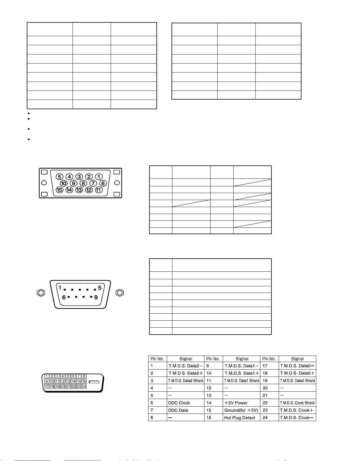
RGB INPUT TERMINAL
Pin No. Input signal Pin No. Input signal
1 Red 9
2 Green 10 Ground
3 Blue 11
∗ The sync switch (TTL/ANALOG switch) is on
the rear of the 13-pin horizontal sync and
14-pin vertical sync terminals.
4
5 Ground 13 Horiz. sync
6 Ground 14 Vert. sync
7 Ground 15
8 Ground
12
Outer side
Ground
Signal
RS-232C INPUT TERMINAL
Pin No.
DVI-D INPUT TERMINAL
Pin No. No. signal
1 DCD (Data Carrier Detect)
2 RD (Receive Data)
3 TD (Transmit Data)
4 DTR (Data Terminal Ready)
5 GND (Ground)
6 DSR (Data Set Ready)
7 RTS (Request To Send)
8 CTS (Clear To Send)
9 RI (Ring Indication)
- 6 -
Page 60

CONTENTS
IMPORTANT INFORMATION . . . . . . . . . . . . . . . . . . . . . . . . . . . . . . . . . 2
SPECIFICATIONS . . . . . . . . . . . . . . . . . . . . . . . . . . . . . . . . . . . . . . . . . . 4
SETTING SIGNALS . . . . . . . . . . . . . . . . . . . . . . . . . . . . . . . . . . . . . . . . 5
CONNECTION . . . . . . . . . . . . . . . . . . . . . . . . . . . . . . . . . . . . . . . . . . . . . 7
PART NAMES AND FUNCTIONS . . . . . . . . . . . . . . . . . . . . . . . . . . . . . 8
VIDEO MODE ADJUSTMENT . . . . . . . . . . . . . . . . . . . . . . . . . . . . . . . . 10
RGB MODE ADJUSTMENT . . . . . . . . . . . . . . . . . . . . . . . . . . . . . . . . .
TROUBLESHOOTING USING LED AND OSD . . . . . . . . . . . . . . . . . .
TROUBLESHOOTING FLOWCHART . . . . . . . . . . . . . . . . . . . . . . . . . .
TROUBLESHOOTING PANEL . . . . . . . . . . . . . . . . . . . . . . . . . . . . . . . .
MAIN POWER SELECTOR SWITCH ADJUSTMENT . . . . . . . . . . . . .
EXPLANATION OF LABELS . . . . . . . . . . . . . . . . . . . . . . . . . . . . . . . . .
REPLACEMENT PARTS AND REQUIRED ADJUSTMENT
. . . . . . . .
VR AND TEST POINT LOCATION . . . . . . . . . . . . . . . . . . . . . . . . . . .
GENERAL CONNECTION DIAGRAM . . . . . . . . . . . . . . . . . . . . . . . . . .
DISASSEMBLY PROCEDURES . . . . . . . . . . . . . . . . . . . . . . . . . . . . . . .
11
12
13
16
19
20
21
22
23
24
59
PARTS LIST . . . . . . . . . . . . . . . . . . . . . . . . . . . . . . . . . . . . . . . . . . . . . .
TRANSPORTATION AND HANDLING RESTRICTIONS. . . . . . . . . . .
61
- 1 -
Page 61

IMPORTANT INFORMATION
WARNING : TO REDUCE THE RISK OF FIRE AND ELECTRIC SHOCK, DO NOT EXPOSE THIS
PRODUCT TO RAIN OR MOISTURE.
Please use a screen saver to prevent burning of an after-image on the screen.
Electrical energy can perform many useful functions. This unit has been engineered and manufactured to assure your
personal safety. But IMPROPER USE CAN RESULT IN POTENTIAL ELECTRICAL SHOCK OR FIRE HAZARD.
In order not to defeat the safeguards incorporated into this unit, observe the following basic rules governing its installation,
use and service. Please read these "Important Safeguards" carefully before use.
Read all the safety and operating instructions before operating the unit.
Retain the safety and operating instructions for future reference.
Adhere to all warnings on the unit and in the operating instructions.
Follow all operating instructions.
Unplug the unit from the wall outlet before cleaning. Do not use liquid or aerosol cleaners. Use a damp cloth for cleaning.
Do not use attachments not recommended by the manufacturer as they may be hazardous.
Do not use the unit near water. Do not use the unit immediately after moving it from a low temperature to a high
temperature environment, as this causes condensation, which may result in fire, electric shock, or other hazards.
Do not place the unit on an unstable cart, stand, or table. The unit may fall, causing serious injury to a child or adult, and
serious damage to the unit. Mount the unit according to the manufacturer's instructions, using the mount recommended by
the manufacturer.
When the unit is used on a cart, avoid quick stops, excessive force, and uneven
surfaces which may cause the unit and cart to overturn, damaging the unit or
causing possible injury to the operator.
When transporting by car, place the unit as shown in the figure.
Slots and openings in the cabinet are provided for ventilation. These ensure reliable operation and protect the unit from
overheating. These openings must not be blocked or covered. (The openings should never be blocked by placing the unit
on a bed, sofa, rug, or similar surface. The unit should not be placed in a built - in installation such as a bookcase or rack
unless proper ventilation is provided and the manufacturer's instructions are adhered to.) For proper ventilation, separate
the unit from other equipment, which may obstruct ventilation. Keep the unit at least 10cm from other equipment.
Operate only with the type of power source indicated on the label. If you are not sure of the type of power supply to your
home, consult your dealer or local power company.
This unit is equipped with a three-wire plug. This plug will fit only into a grounded power outlet. If you cannot insert the plug
into the outlet, have an electrician install the proper outlet. Do not defeat the safety purpose of the grounded plug.
Route power cords so that they are not likely to be walked on or pinched by items placed on or against them. Pay
particular attention to cords at doors, plugs, receptacles, and where they exit from the unit.
For added protection during a lightning storm, or when the unit is left unattended and unused for long periods of time,
unplug it from the wall outlet and disconnect the cabling. This will prevent damage to the unit by lighting and power line
surges.
Do not overload wall outlets, extension cords, or convenience receptacles on other equipment as this can result in fire or
electric shock.
Never push objects of any kind into this unit through openings as they may touch dangerous voltage points or short-circuit
parts that could result in a fire or electric shock. Never spill liquid of any kind onto the unit.
- 2 -
Page 62

Do not attempt to service this unit yourself as opening or removing covers may expose you to dangerous voltages and
other hazards. Have all service done by qualified service personnel.
Unplug this unit from the wall outlet and have it serviced by qualified service personnel in the following cases:
a) If the power supply cord or plug is damaged.
b) If liquid has been spilled, or objects have fallen onto the unit.
c) If the unit has been exposed to rain or water.
d) If the unit does not operate normally by following the operating instructions. Adjust only those controls that are
covered by the Operation Manual, as improper adjustment of controls may result in damage and will often require
extensive work by a qualified technician to restore the unit to normal operation.
e) If the unit has been dropped or damaged in any way.
f) A distinct change in performance indicates that service is required.
When required, be sure the service technician uses replacement parts specified by the manufacturer or parts with the
same characteristics as the original parts. Unauthorized substitutions may result in fire, electric shock, or other hazards.
Upon completion of any service of repairs, ask the service technician to perform safety checks to determine that the
unit is in proper operating condition.
Place the unit more than one foot away from heat sources such as radiators, heat registers, stoves, and other devices
(including amplifiers) that produce heat.
When connecting other devices such as VCR's and personal computers, turn off the power to this unit to protect
against electric shock.
Do not place combustibles such as cloth, paper, matches, aerosol cans or gas lighters that prevent special hazards
when overheated behind the cooling fan.
Use only the accessory cord designed for this unit to prevent shock.
The power supply voltage rating of this unit is AC100-240V, but the attached power cord conforms to the following
power supply voltage. Use only the Power Cord designated by our dealer to ensure Safety and EMC.
When used with other power supply voltages, the power cable must be changed.
Consult your local dealer.
Power Cord
Power supply voltage : AC 100 - 125 V AC 200 - 240 V AC-240V
(SAA TYPE)
- 3 -
 Loading...