

Page 1
P42HTS40WS
P-TU4240WS
P42HTS40ES
P-TU4240ES
FUJITSU GENERAL Proprietary
Copy Prohibited
Page 2

CONTENTS
IMPORTANT INFORMATION . . . . . . . . . . . . . . . . . . . . . . . . . . . . . . . . . . . 2
SPECIFICATIONS . . . . . . . . . . . . . . . . . . . . . . . . . . . . . . . . . . . . . . . . . . . . 4
SETTING SIGNALS . . . . . . . . . . . . . . . . . . . . . . . . . . . . . . . . . . . . . . . . . . 6
CONNECTION . . . . . . . . . . . . . . . . . . . . . . . . . . . . . . . . . . . . . . . . . . . . . . 8
PART NAMES AND FUNCTIONS . . . . . . . . . . . . . . . . . . . . . . . . . . . . . 14
VIDEO MODE ADJUSTMENT . . . . . . . . . . . . . . . . . . . . . . . . . . . . . . . . 19
RGB MODE ADJUSTMENT . . . . . . . . . . . . . . . . . . . . . . . . . . . . . . . . . . 21
TROUBLESHOOTING USING LED AND OSD . . . . . . . . . . . . . . . . . . . 23
TROUBLESHOOTING FLOWCHART . . . . . . . . . . . . . . . . . . . . . . . . . . . 24
VOLTAGE OF EACH CONNECTOR
VS AND VA ADJUSTMENT . . . . . . . . . . . . . . . . . . . . . . . . . . . . . . . . . . . . 32
GENERAL CONNECTION DIAGRAM . . . . . . . . . . . . . . . . . . . . . . . . . . 33
DISASSEMBLY .
EXPLODED VIEW .
PARTS LIST . . . . . . . . . . . . . . . . . . . . . . . . . . . . . . . . . . . . . . . . . . . . . . . 58
TRANSPOR
. . . . . . . . . . . . . . . . . . . . . . . . . . . . . . . . . . . . . . . . . . . . . 37
. . . . . . . . . . . . . . . . . . . . . . . . . . . . . . . . . . . . . . . . . . . 53
TATION AND HANDLING RESTRICTIONS . . . . . . . . . . . . 60
. . . . . . . . . . . . . . . . . . . . . . . . . . . . 31
Page 3
IMPORTANT INFORMATION
WARNING : TO REDUCE THE RISK OF FIRE AND ELECTRIC SHOCK, DO NOT EXPOSE THIS
PRODUCT TO RAIN OR MOISTURE.
Please use a screen saver to prevent burning of an after-image on the screen.
Electrical energy can perform many useful functions. This unit has been engineered and manufactured to assure your
personal safety. But IMPROPER USE CAN RESULT IN POTENTIAL ELECTRICAL SHOCK OR FIRE HAZARD.
In order not to defeat the safeguards incorporated into this unit, observe the following basic rules governing its installation,
use and service. Please read these "Important Safeguards" carefully before use.
Read all the safety and operating instructions before operating the unit.
Retain the safety and operating instructions for future reference.
Adhere to all warnings on the unit and in the operating instructions.
Follow all operating instructions.
Unplug the unit from the wall outlet before cleaning. Do not use liquid or aerosol cleaners. Use a damp cloth for cleaning.
Do not use attachments not recommended by the manufacturer as they may be hazardous.
Do not use the unit near water. Do not use the unit immediately after moving it from a low temperature to a high
temperature environment, as this causes condensation, which may result in fire, electric shock, or other hazards.
Do not place the unit on an unstable cart, stand, or table. The unit may fall, causing serious injury to a child or adult, and
serious damage to the unit. Mount the unit according to the manufacturer's instructions, using the mount recommended by
the manufacturer.
When the unit is used on a cart, avoid quick stops, excessive force, and uneven
surfaces which may cause the unit and cart to overturn, damaging the unit or
causing possible injury to the operator.
When transporting by car, place the unit as shown in the figure.
Slots and openings in the cabinet are provided for ventilation. These ensure reliable operation and protect the unit from
overheating. These openings must not be blocked or covered. (The openings should never be blocked by placing the unit
on a bed, sofa, rug, or similar surface. The unit should not be placed in a built - in installation such as a bookcase or rack
unless proper ventilation is provided and the manufacturer's instructions are adhered to.) For proper ventilation, separate
the unit from other equipment, which may obstruct ventilation. Keep the unit at least 10cm from other equipment.
Operate only with the type of power source indicated on the label. If you are not sure of the type of power supply to your
home, consult your dealer or local power company.
This unit is equipped with a three-wire plug. This plug will fit only into a grounded power outlet. If you cannot insert the plug
into the outlet, have an electrician install the proper outlet. Do not defeat the safety purpose of the grounded plug.
Route power cords so that they are not likely to be walked on or pinched by items placed on or against them. Pay
particular attention to cords at doors, plugs, receptacles, and where they exit from the unit.
For added protection during a lightning storm, or when the unit is left unattended and unused for long periods of time,
unplug it from the wall outlet and disconnect the cabling. This will prevent damage to the unit by lighting and power line
surges.
Do not overload wall outlets, extension cords, or convenience receptacles on other equipment as this can result in fire or
electric shock.
Never push objects of any kind into this unit through openings as they may touch dangerous voltage points or short-circuit
parts that could result in a fire or electric shock. Never spill liquid of any kind onto the unit.
- 2 -
Page 4

Do not attempt to service this unit yourself as opening or removing covers may expose you to dangerous voltages and
other hazards. Have all service done by qualified service personnel.
Unplug this unit from the wall outlet and have it serviced by qualified service personnel in the following cases:
a) If the power supply cord or plug is damaged.
b) If liquid has been spilled, or objects have fallen onto the unit.
c) If the unit has been exposed to rain or water.
d) If the unit does not operate normally by following the operating instructions. Adjust only those controls that are
covered by the Operation Manual, as improper adjustment of controls may result in damage and will often require
extensive work by a qualified technician to restore the unit to normal operation.
e) If the unit has been dropped or damaged in any way.
f) A distinct change in performance indicates that service is required.
When required, be sure the service technician uses replacement parts specified by the manufacturer or parts with the
same characteristics as the original parts. Unauthorized substitutions may result in fire, electric shock, or other hazards.
Upon completion of any service of repairs, ask the service technician to perform safety checks to determine that the
unit is in proper operating condition.
Place the unit more than one foot away from heat sources such as radiators, heat registers, stoves, and other devices
(including amplifiers) that produce heat.
When connecting other devices such as VCR's and personal computers, turn off the power to this unit to protect
against electric shock.
Do not place combustibles such as cloth, paper, matches, aerosol cans or gas lighters that prevent special hazards
when overheated behind the cooling fan.
Use only the accessory cord designed for this unit to prevent shock.
The power supply voltage rating of this unit is AC100-240V, but the attached power cord conforms to the following
power supply voltage. Use only the Power Cord designated by our dealer to ensure Safety and EMC.
When used with other power supply voltages, the power cable must be changed.
Consult your local dealer.
Power Cord
Power supply voltage : AC 100 - 125 V AC 200 - 240 V AC-240V
(SAA TYPE)
- 3 -
Page 5

SPECIFICATIONS
Power requirement
PDP UNIT
SELECTOR UNIT
Current drain
PDP UNIT
SELECTOR UNIT
Display panel
Screen size 92.2(W) X 52.2(H) [cm]
Aspect ratio 16 : 9
Number of pixels 1,024(H) X 1024(V) pixels
Pixel pitch 0.90mm X 0.51mm
Contrast ratio 1000 : 1
Luminance 1100 cd/m
Viewing angle Max. 160 degrees
Input/Output Terminals of
PDP unit
DVI input DVI-D terminal
Display frequency Horizontal : 33.75MHz
Digital(optical) audio input
Effective max.
output
Input/Output Terminals of
SELECTOR unit
S video input
Component video input
Video input (E model)
S video
Digital RGB1 input
110-240V, 50/60Hz
110-240V, 50/60Hz
4.2A-1.8A
0.45-0.27A
36.3(W) X 20.6(H) [inch]
2
Differential Input 0.5 10%
+ + + +
(RXC , RX0 , RX1 , RX2 )
Vertical : 60Hz
Dot clock : 40.5MHz
Optical Input
-27dB to -14.5dB
Level terminal
10W+10W (L/R), 6
1.0V /75
P-P
S terminal
Y signal : 1.0V /75P-P
C signal : 0.286V /75P-P
Three RCA terminals
(one system)
Y : 1.0V /75P-P
Pb/B-Y : 0.7V /75P-P
Pr/R-Y : 0.7V /75P-P
SCART terminal
1.0V /75Video
P-P
Y signal : 1.0V /75
C signal : 0.286V /75
G : 0.7V /75RGB
B : 0.7V /75
R : 0.7V /75
P-P
P-P
P-P
P-P
P-P
DVI-D terminal
Differential Input 0.5 10%
+ + + +
(RXC , RX0 , RX1 , RX2 )
Analog RGB2/
RGB3 input
mD-sub : 15pin(3 row type)
Video : 0.7V /75
P-P
SYNC signal : TTL level
8 memories (each RGB1,2,3)User set mode
Display frequency
Horizontal : 15.63 to 80.0MHz
Vertical : 50.0 to 120Hz
Dot clock : 50MHz Max.
XGA 68MHz
Digital RGB1 output
Analog audio input
DVI-D terminal
Differential Input 0.5 10%
+ + + +
(RXC , RX0 , RX1 , RX2 )
+
Two RCA terminals
(one system)
500mVrms/22K
Digital(optical) audio
input
+
Optical Input
-24dB to -14.5dB
Digital(optical) audio
output
for Display
for audio amp
Color system
Optical Input
-21dB to -15dB
-21dB to -15dB
NTSC/PAL/SECAM/N-PAL/M-PAL
/4.43NTSC/PAL60
Display colors
1.07 billion (1,024 each for R.G.B.)
Outer dimensions
PDP UNIT
Width : 103.9cm (40.9 inch)
Height : 64.0cm (25.2 inch)
Depth : 8.7cm (3.4 inch)
SELECTOR UNIT
Width : 43.0cm (16.9 inch)
Height : 9.5cm (3.7 inch)
Depth : 35.0cm (13.8 inch)
Net weight
PDP UNIT
SELECTOR UNIT
31.5kg (69.0lbs)
5.0kg (11.0lbs)
Environment (Operating)
Temperature 0 to 40
Relative humidity 20 to 80%
Pressure 800 to 1,114 hPa
Accessories
PDP UNIT
Power cord
System cable (Video)
System cable (Audio)
SELECTOR UNIT
2 User's manual
Remote controller
Batteries (Type AA x 2)
+
Power cord
Ferrite core
Antenna input TV 75
- 4 -
Page 6

Options
Stand P-TT4202
Wall mounting unit P-WB4201
Hanging unit
Speaker
Standards
0 to 15 mounting angle
P-CT4200
0 to 15 mounting angle
P-SP4200
P-SP1000
P-ST4200Speaker stand
P42HTS40WS
P42HTS40ES
P-TU4240WS
P-TU4240ES
UL,CSA
Safety:
UL6500 UL6500
C-UL C-UL
EMC: FCC Part15 Class B FCC Part15 Class B
ICES-003 Class B ICES-003 Class B
CE
Safety: EN60065
EMC : EN55022
EN61000-3-2 1995
1998
EN60065
EN55013
EN55020
EN61000-3-3, 1995
EN55024 1998
EN61000-4-2, 1995
EN61000-4-3, 1996
EN61000-4-4, 1995
EN61000-4-5, 1995
EN61000-4-6, 1996
EN61000-4-8, 1993
EN61000-4-11,1994
AS
Safety : IEC60065 IEC60065
EMC : AS/NZS 3548 AS/NZS 1053
2001
1994
- 5 -
Page 7
SETTING SIGNALS
This display can store parameter settings for eight additional signals for RGB.
To do this, select the desired signal and follow "RGB MODE ADJUSTMENT" in the manual to adjust the parameters.
When you finish, the settings will be automatically stored.
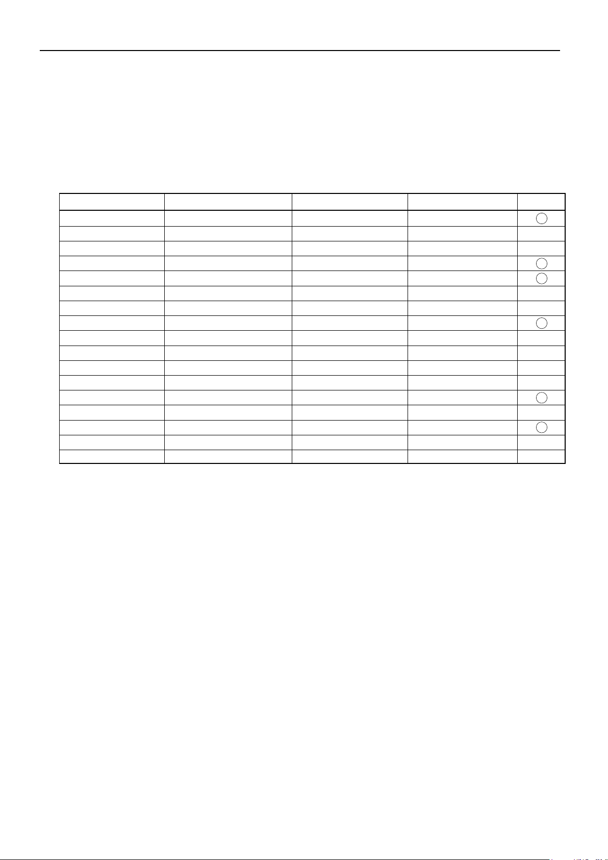
FACTORY SET SIGNALS (RGB MODE)
Main corresponding signals (RGB mode)
Display (dots x lines)
640 x 480 31.47 59.94 VGA
640 x 480
640 x 480
720 x 400
800 x 600
800 x 600
800 x 600
1024 x 768
1024 x 768
1024 x 768
1280 x 1024 63.98 60.02 SXGA 60 Hz
1280 x 1024 79.98 75.03 SXGA 75 Hz
848 x 480 31.02 60.00
852 x 480 31.72
1360 x 768
720 x 485 15.73 59.94 60 fields
720 x 575 15.63 50.00 50 fields
*With some input signals, "Out of range" may appear even when the horizontal and vertical frequencies are within their permissible ranges.
In this event, match the input signals to another frequency rather than those listed above.
* In the DVI-D mode, the input signal can be restricted partly.
Horizontal frequency (kHz) Vertical frequency (Hz)
37.50 75.00
43.27 85.01
31.47 70.09
37.88 60.32
46.88 75.00 SVGA 75 Hz
53.67 85.06 SVGA 85 Hz
48.36 60.00 XGA 60 Hz
60.02
68.68
47.71
75.03
84.99
59.97
60.01
VGA 75 Hz
VGA 85 Hz
400 lines
SVGA 60 Hz
XGA 75 Hz
XGA 85 Hz
Signal DVD-I
- 6 -
Page 8
FACTORY SET SIGNALS (Component video mode)
Horizontal
frequency (kHz)
15.73 SDTV 480i
15.63 SDTV 576i
31.47 SDTV 480p
31.25 SDTV 576p
45.00 HDTV 720p
37.50 HDTV 720p
33.75 HDTV 1,080i
28.13 HDTV 1,080i
The dedicated graphics card is optional.
In the 800 x 600 and 1,024 x 768 modes, images of reduced size are displayed on the screen, using size reduction and
interpolation. Also note that on-screen information is also displayed in reduced size.
" Out of range" appears if the display receives a signal whose characteristic does not fall within the display's
permissible range.
You can check the input signals with "Information" on the OTHERS Menu screen.
Vertical
frequency (Hz)
59.94
50.00
59.94
50.00
60.00
50.00
60.00
50.00
Signal
FACTORY SET SIGNALS (Video, S-video mode)
Horizontal
frequency (kHz)
15.73 NTSC
15.63 PAL
15.63 SECAM
15.63 PAL 60
15.63 N-PAL
15.73 M-PAL
15.73 4.43 NTSC
Vertical
frequency (Hz)
59.94
50.00
50.00
59.52
50.00
59.95
59.94
Signal
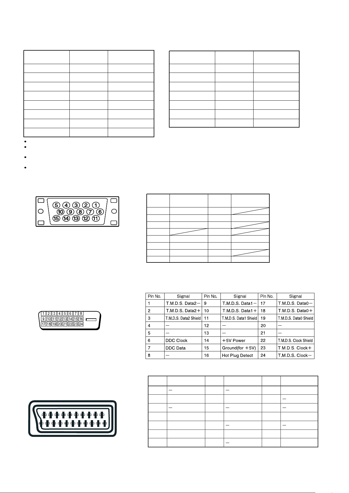
RGB INPUT TERMINAL
Pin No. Input signal Pin No. Input signal
1 Red 9
2 Green 10 Ground
3 Blue 11
* The sync switch (TTL/ANALOG switch) is on
the rear of the 13-pin horizontal sync and
14-pin vertical sync terminals.
4
5 Ground 13 Horiz. sync
6 Ground 14 Vert. sync
7 Ground 15
8 Ground
12
Outer side
Ground
DVI-D INPUT TERMINAL
SCART TERMINAL
48121620
26101418
159131721
37111519
Pin No.
Input Signal
1
2 Right audio
3
4
Audio ground
5Blue ground
6Left audio
7 Blue
Pin No.
Input Signal
8
9
Green ground
10
11 Green
12
13 Red ground
14
Pin No.
15
Input Signal
Red/chrominance
16
17
18
Composite video ground
19
20
Composite video/Y
21 Ground
- 7 -
Page 9
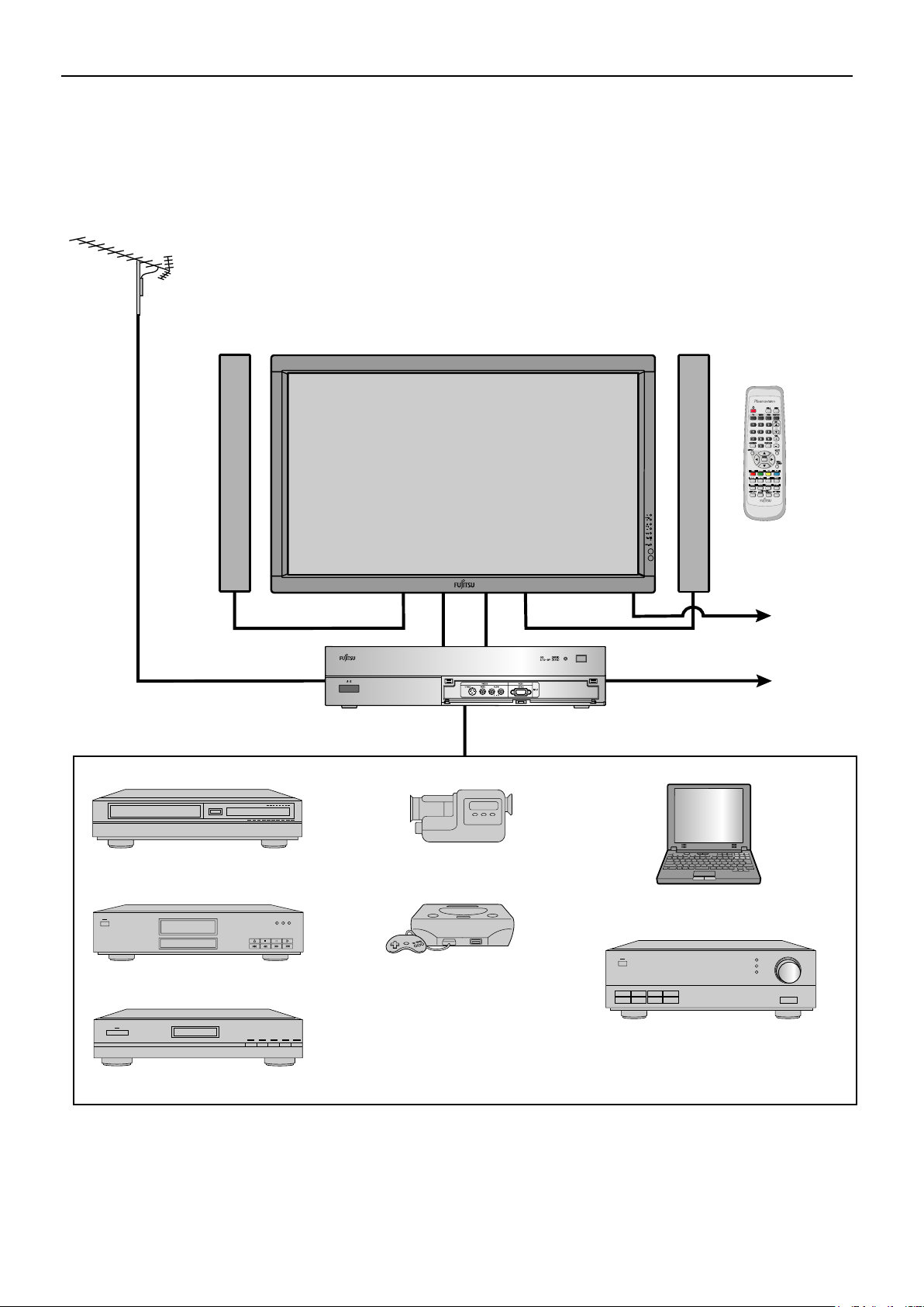
CONNECTION
EXAMPLE OF CONNECTION TO EXTERNAL COMPONENTS
Antenna (commercially available product)
Speaker Display Speaker (optional)
Remote
control
VCR or other external components See P.
VCR P- 9
DVD recorder/player P-1 0
Videogame machine P-11
To AC outlet
To AC outlet
AV Selector
Video camera P-11
PC P-12
Audio amplifier P-13
Satellite tuner P-10
- 8 -
Page 10
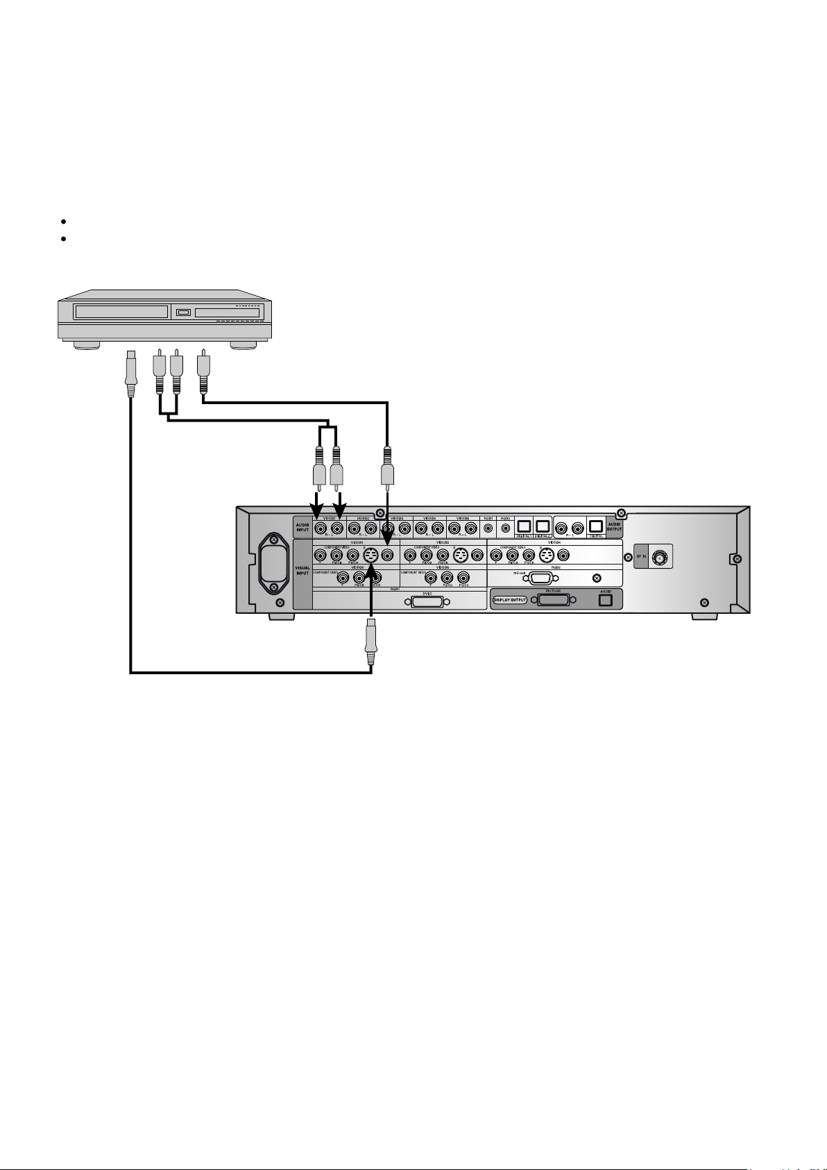
Model : P42HTS40W
VCR
Connect the video signal cable to either the S-video input terminal or the video input terminal.
If the unit to be connected is equipped with S-video output, it is recommended to connect the S-video terminal.
To S-video
output
To audio outputs
To video output
To audio inputs To video input
To S-video input
Rear side of AV Selector
- 9 -
Page 11
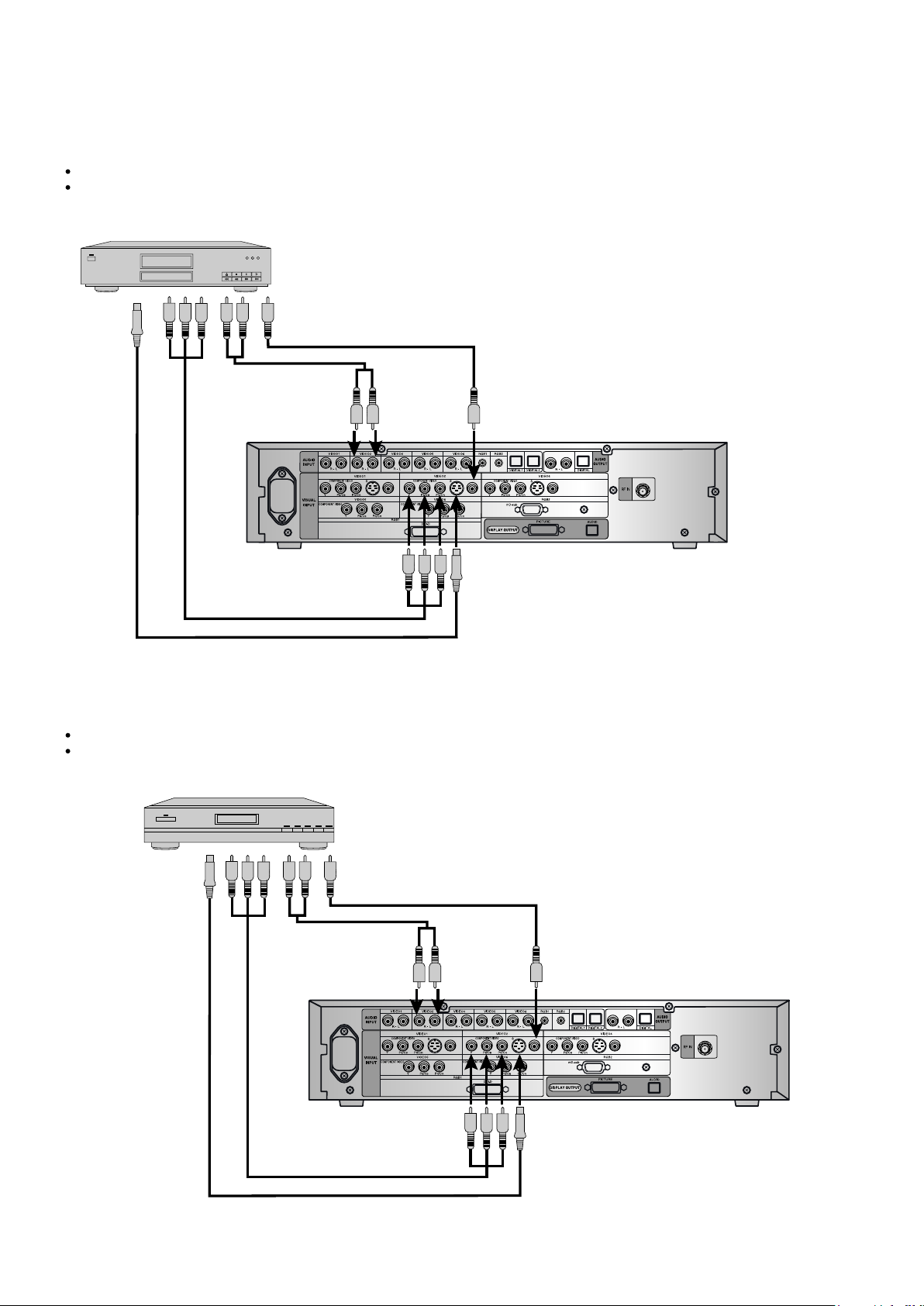
DVD RECORDER / PLAYER
Connect the video signal cable to the component video input terminal, S-video input terminal, or the video input terminal.
If the component to be connected is equipped with component video output terminal, it is recommended to connect to the
component video terminal.
To video output
To S-video
output
To audio outputs
To component
video output
To audio
inputs
To video input
Rear side of AV Selector
To component video input
To S-video input
SATELLITE TUNER
Connect the video signal cable to the component video input terminal, S-video input terminal, or the video input terminal.
If the component to be connected is equipped with component video output terminal, it is recommended to connect to
the component video terminal.
To S-video
output
To video output
To audio outputs
To component
video output
To component video input
To audio
inputs
To video input
Rear side of AV Selector
To S-video input
- 10 -
Page 12
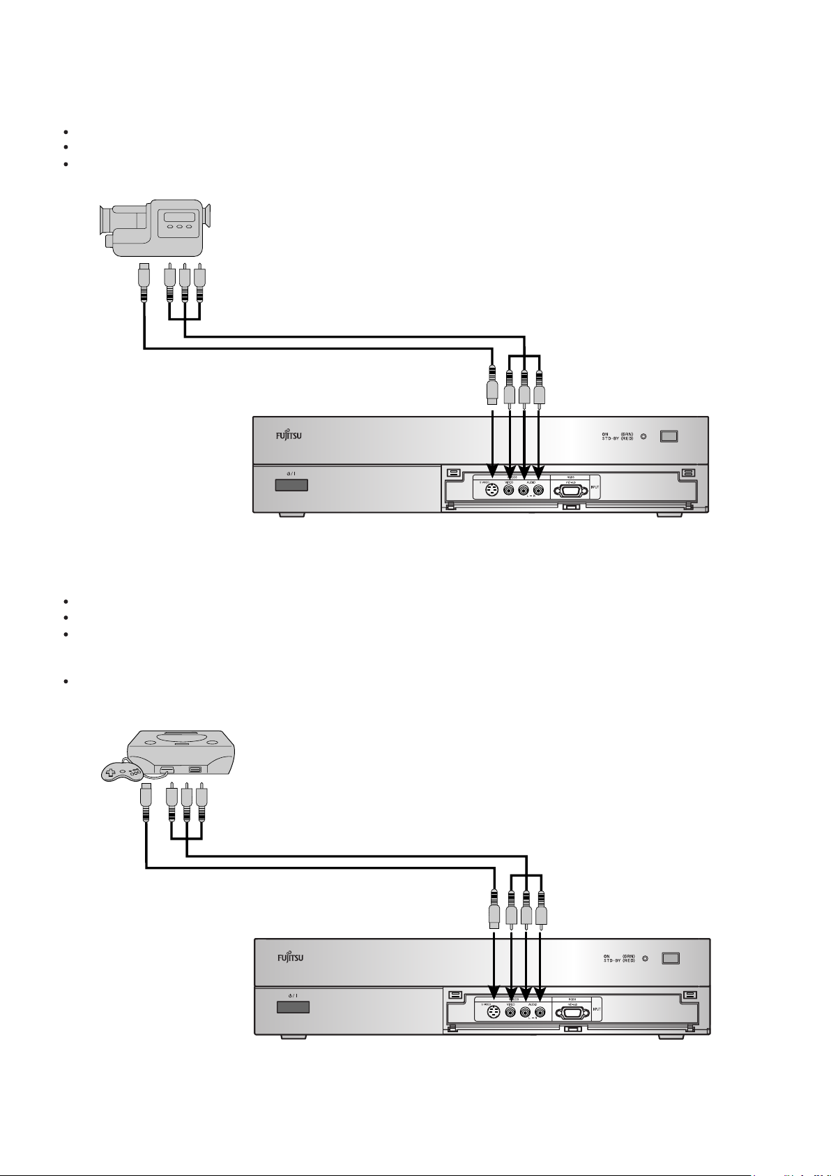
VIDEO CAMERA
A Video camera can conveniently be connected to the Video 3 input on the front side.
Connect the video signal cable to either the S-video input terminal or the video input terminal.
If the unit be connected is equipped with S-video output terminal, it is recommended to connect to the S-video terminal.
To video and audio outputs
To S-video output
To S-video input
To video and audio inputs
Front side of AV Selector
VIDEOGAME MACHINE
As the connecting cable differs with videogame machines, please consult the instructions for your videogame machine.
Connect the video signal cable to either the S-video input terminal or the video input terminal.
Ensure that the same image (pattern) is not displayed on the screen for an extended period. If the same image is displayed
on the screen for an extended period, the brightness of that part of the screen may change and image burn-in may leave an
after-image on the screen.
If the videogame machine to be connected is equipped with S-video output terminal, it is recommended to connect to the S-video terminal.
To video and audio tputs
To S-video output
To video and audio inputs
To S-video input
Front side of AV Selector
- 11 -
Page 13
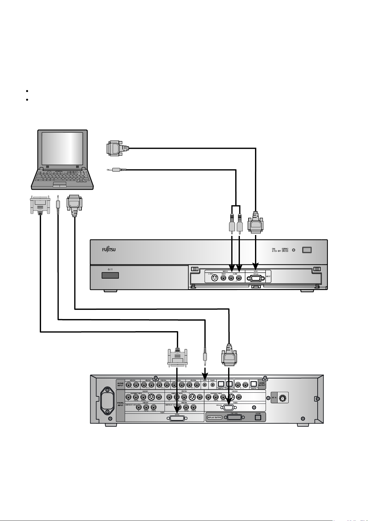
PC
As the cable for connecting a PC differs with the PC model, please consult your dealer for information on the right cable to purchase.
The PC can be connected to either the front side or the rear side, whichever is most convenient.
To RGB output (mD-sub)
To audio output
To RGB output (mD-sub)
To audio output
To RGB output (DVI-D)
To audio input
To mD-sub input
When connecting to the front side of the AV Selector
To audio
input
To DVI-D input
To mD-sub input
When connecting to the rear side of the AV Selector
- 12 -
Page 14
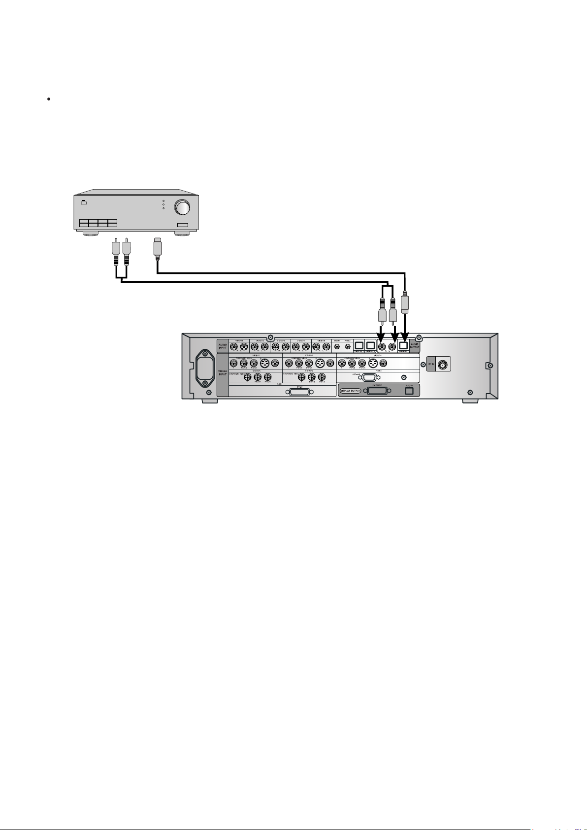
WHEN OUTPUTTING AUDIO SIGNALS TO AN AUDIO AMPLIFIER
Connect the audio signal cables to the digital output and the analog audio output terminals.
The signal input as digital input is not output as analog audio.
*
The digital audio input terminal on the display complies with a sampling frequency of 48 kHz.
*
In the case of outputs with another frequency, connect to an audio system (amplifier).
To digital audio input
To analog audio input
To digital audio outputTo analog audio output
Rear side of AV Selector
- 13 -
Page 15
PART NAMES AND FUNCTIONS
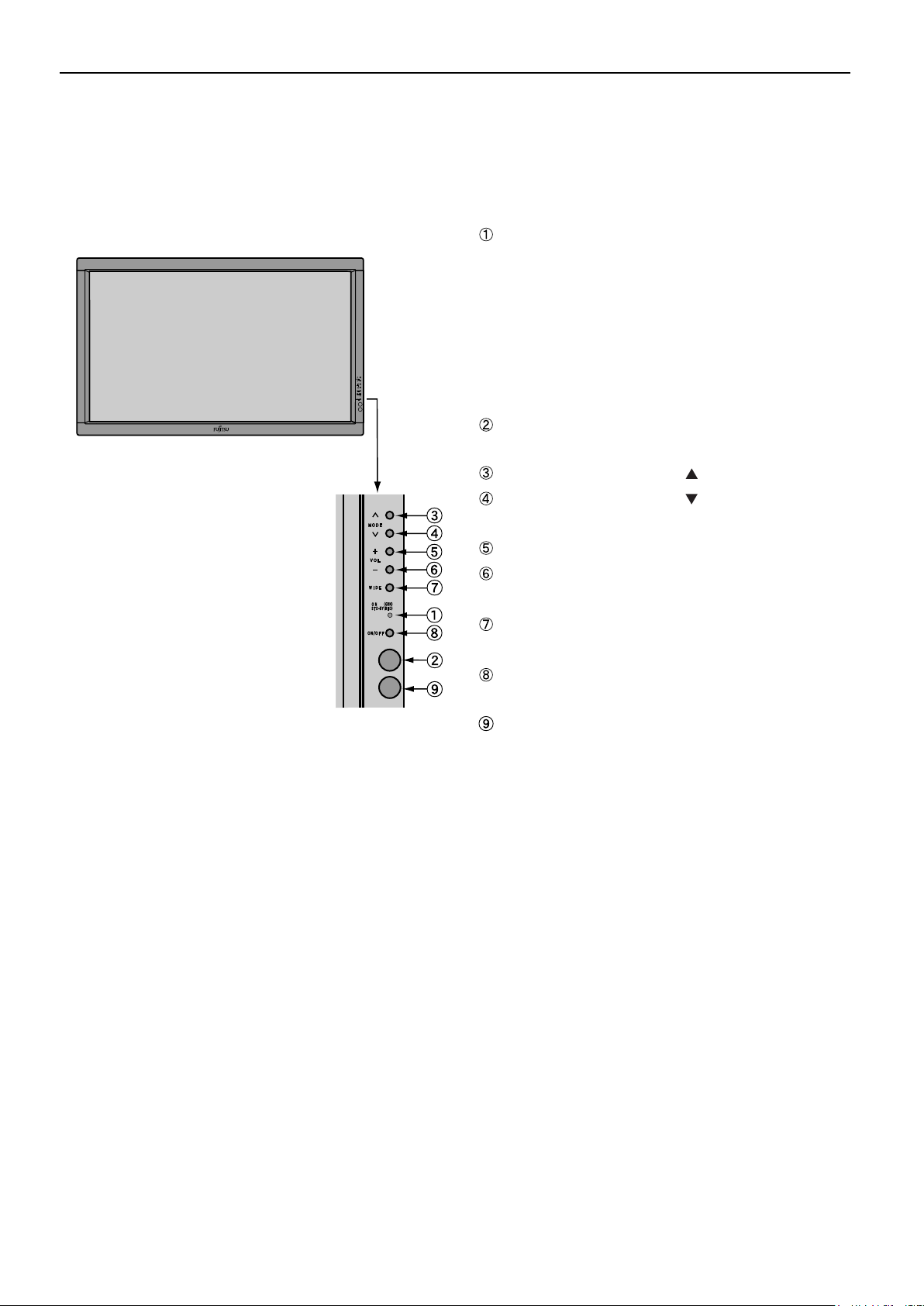
DISPLAY SECTION – FRONT
Power indicator lamp
(Right section)
This lamp shows the state of the power supply.
Remote control signal receiver
Receives signals from the remote control.
Input mode selector button
Input mode selector button
Switches between picture input modes.
VOL + button
VOL - button
Adjusts the sound volume.
Wide screen selector button [WIDE]
Switches the screen over to a desired wide screen.
ON/OFF button
Tu
Ambient Sensor
Detects the brightness of external light.
Do not obstruct it.
Lit (red): Stand-by state
Lit (green): Power ON state
Lit (orange): Power saving (DPMS: Power saving
function) mode ON
Flashing (red): Malfunction (Flashes differently depending
on the type of malfunction.)
[MODE]
[MODE]
rns the power "ON" and "OFF (standby state)".
- 14 -
Page 16
Model : P42HTS40W/E
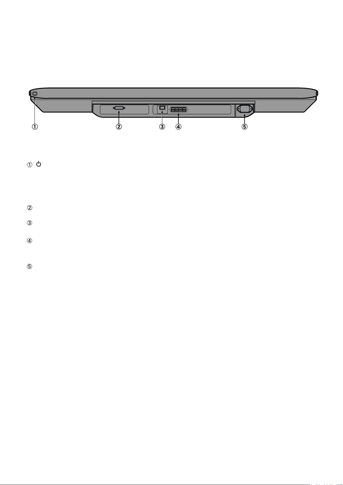
DISPLAY SECTION – LOWER PART
/I power switch
If this button is pressed when the power indicator lamp is off, the indicator lamp will light.
The power can be turned on and the standby mode selected by using the remote control or the control panel of the display.
If this button is pressed when the power indicator lamp is lit, the indicator lamp will go out.
* Power is still supplied to parts of the display even if the indicator lamp is off.
Display input (Picture) terminal
Connect this terminal to the display output (picture) terminal on the AV Selector using the special cable provided.
Display input (audio) terminal
Connect this terminal to the display output (audio) terminal on the AV Selector using the special cable provided.
External speaker output terminal (EXP SP)
Connect this terminal to the optionally available speaker.
When connecting a cable, attach a ferrite core to the cable.
Power input terminal
Connect this terminal to the power cable supplied with the display.
When connecting a cable, attach a ferrite core to the cable.
- 15 -
Page 17
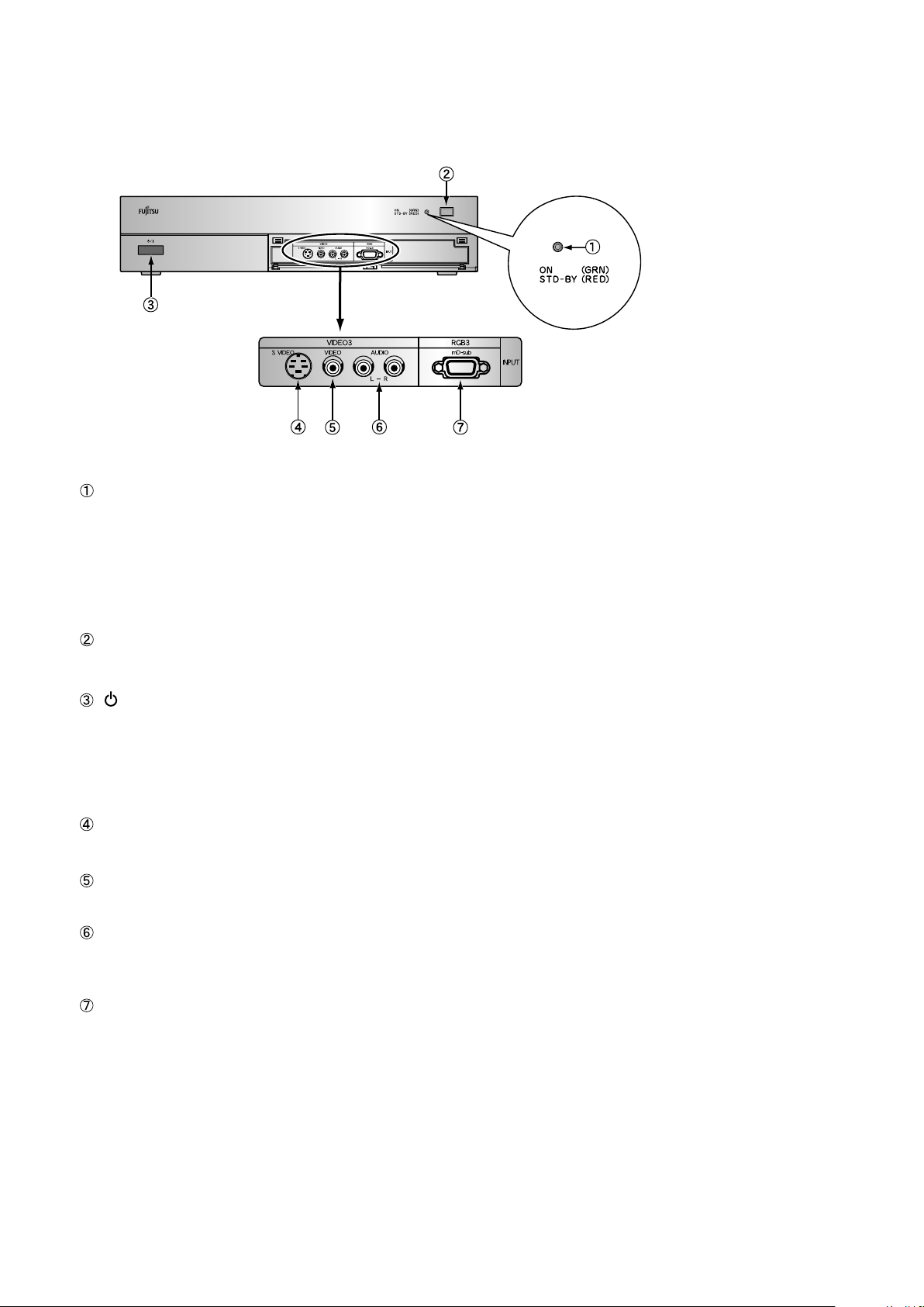
AV SELECTOR SECTION - FRONT
Power indicator lamp
This lamp shows the state of the power supply.
Lit (red): Stand-by state
Lit (green): Power ON state
Flashing (red or green): Malfunction (Flashes differently depending
on the type of malfunction.)
Remote control signal receiver
Receives signals from the remote control.
/I power switch
If this button is pressed when the power indicator lamp is off, the indicator lamp will light.
The power can be turned on and the standby mode selected by using the remote control or the control panel of the display.
If this button is pressed when the power indicator lamp is lit, the indicator lamp will go out.
* Power is still supplied to parts of the display even if the indicator lamp is off.
Video3, S-video input terminal
Connect this terminal to the S-video output terminal of your video camera etc.
Video3, video input terminal
Connect this terminal to the video output terminal of your video camera etc.
Audio input terminal (L/R)
These are the audio input terminals for the Video3 and RGB3 terminals.
Input the audio for the video to be seen here.
RGB3 input terminal
Connect this terminal to your PC's mD-sub output terminal.
- 16 -
Page 18
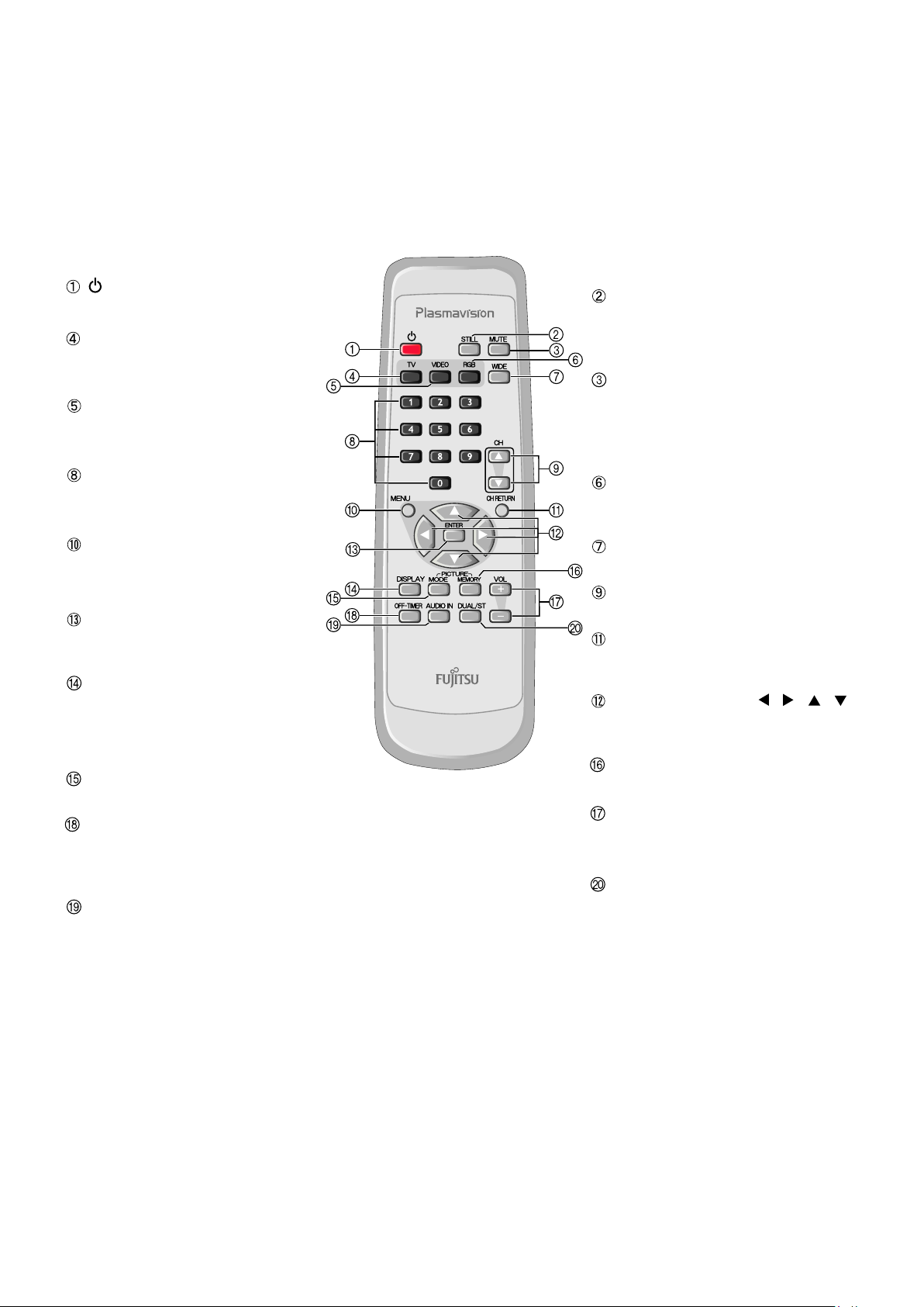
Model : P42HTS40W
REMOTE CONTROL
button
Switches between power ON and standby.
TV input mode selector button
P
ress this button to watch terrestrial
broadcastings.
Video input mode selector button
Press this button to switch through
Video1 to Video6.
Number buttons
Use these buttons for the Program No.
selection directly.
Menu button [MENU]
Press this button to display the menu
screen for adjusting the picture and/
or the audio.
Enter button [ENTER]
Press this button to fix the entry in the
ADJUSTMENT MENU.
DISPLAY button
Press this button to display the Program
No. input mode, and screen size status.
The status is displayed for about five
seconds.
PICTURE MODE button
Use this button to switch the Picture Mode.
OFF-TIMER button
Use this button to specify the length of
time until the power turns off (stand-by
state)
AUDIO IN button
Press this button to select audio input.
STILL button
Displays the screen being watched as the still
picture.To return to normal, press this button
once again.
MUTE button
T
emporarily mutes the audio.
To return the audio to normal, press this
button once again, or press the VOL+
does the VOL- work also.
RGB input mode selector button
Press this button to switch through
RGB1 to RGB3.
WIDE button
Switches the screen size.
Channel Up/Down buttons
Press these buttons to select the preset programs.
Channel Return button
Return to the previous Program No. and
input mode immediately.
Adjustment buttons [ / / / ]
Use these buttons to select the item or adjust
the value in the menu screen.
PICTURE MEMOR
Press this button to recall a Picture Memory.
Volume adjustment buttons
[VOL +/ - ]
Press this buttons to adjust the volume.
DUAL/STEREO button
Press this button to select the audio mode for
stereo/dual-channel audio broadcastings.
Y button
- 17 -
Page 19
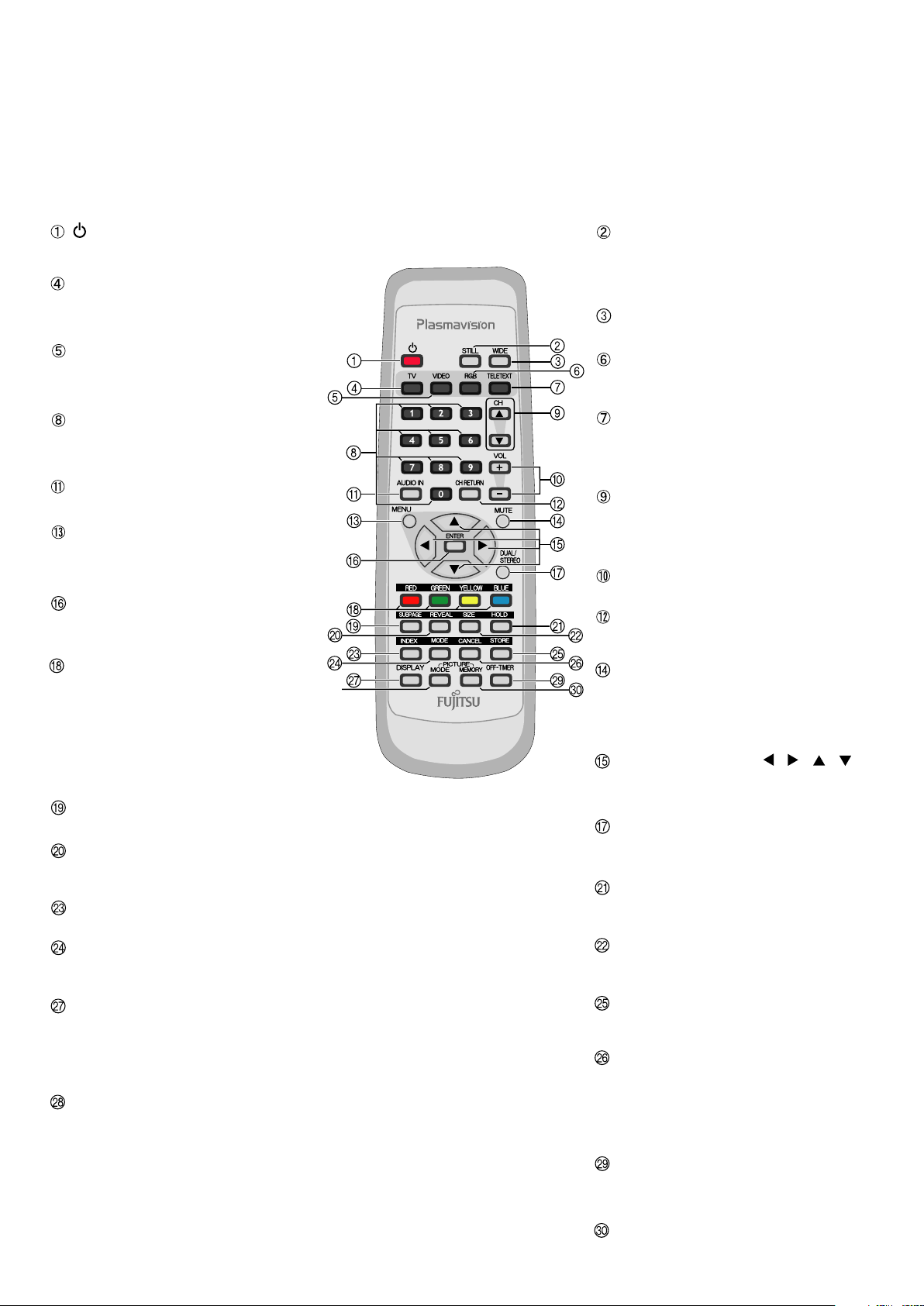
Model : P42HTS40E
REMOTE CONTROL
button
Switches between power ON and standby.
TV input mode selector button
P
ress this button to watch terrestrial
broadcastings.
Video input mode selector button
Press this button to switch through
Video1 to Video6.
Number buttons
Use these buttons for the Program No.
selection directly.
AUDIO IN button
Press this button to select audio input.
Menu button
Press this button to display the menu
screen for adjusting the picture and/
or the audio.
Enter button
Press this b
ADJUSTMENT MENU.
COLOR button
In the teletext broadcasting, press these
buttons to switch through the pages stored
to each of the four colors in the LIST mode.
Other than the LIST mode, these buttons can
also be used for the colored option selected
from the four teletext new options displayed
at the button of the screen.
SUBPAGE button
Press this button to display the SUBPAGE.
REVEAL button
Press this button to display hidden text
(such as the answers to quizzes, etc.).
INDEX button
Press this button to the INDEX page.
MODE button
Switches to the LIST mode. Press this button
once again to return to the current mode.
DISPLAY button
Press this button to display the Program
No. input mode, and screen size status.
The status is displayed for about five
seconds.
PICTURE MODE button
Use this button to switch the Picture Mode.
utton to fix the entry in the
- 18 -
STILL button
Displays the screen being watched as the still
picture.To return to normal, press this button
once again.
WIDE button
Switches the screen size.
RGB input mode selector button
Press this button to switch through
RGB1 to RGB3.
TELETEXT input mode selector button
Press this button to switch to the teletext
broadcasting. (selectable only when watching
the TV.)
Channel Up/Down buttons
Press these buttons to select the preset programs.
Use these buttons to scroll through a page in the
teletext broadcasting.
Volume adjustment buttons
Press these buttons to adjust the volume.
Channel Return button
Return to the previous Program No. and
input mode immediately.
MUTE button
T
emporarily mutes the audio.
To return the audio to normal, press this
button once again, or press the VOL+
does the VOL- work also.
Adjustment buttons [ / / / ]
Use these buttons to select the item or adjust
the value in the menu screen.
DUAL/STEREO button
Press this button to select the audio mode for
stereo/dual-channel audio broadcasting.
HOLD button
Press this button to hold the transmission of
the teletext program you are corrently watching.
SIZE button
Press this button to change the size of the
current watching page.
STORE button
In LIST mode, saves the current display to
the Favorites page.
CANCEL button
Press this button to watch the terrestrial
broadcasting you are watching before you pressed
TELETEXT.
Press it once again to return to the teletext
broadcasting.
OFF-TIMER button
Use this button to specify the length of
time until the power turns off (stand-by
state)
PICTURE MEMOR
Press this button to recall a Picture Memory.
Y button
Page 20

VIDEO MODE ADJUSTMENT
REMOTE CONTROLLER
TV
VOL. +
VOL. -
MUTE
CH
CH
CH. Return
TELETEXT
RED
GREEN
YELLOW
BLUE
STORE
VIDEO 1
VIDEO 2
VIDEO 3
VIDEO 4
VIDEO 5
VIDEO 6
RGB 1
RGB 2
RGB 3
STILL
DISPLAY
PICTURE MODE
PICTURE MEMORY
AUDIO IN
DUAL CH SW
OFF-TIMER
WIDE
Normal
Wide 1
Natural
Fine
Effective
Conventional
Still
Load
Save
Analog Audio
Digital Audio 1
Digital Audio 2
Dual-l
Dual-ll
Stereo
Mono
Off
30 min
60 min
90 min
120 min
Normal
Wide 1
Wide 2
Zoom 1
Zoom 2
Memory 1
Memory 2
Memory 3
Memory 4
Memory 5
Memory 6
Memory 7
Memory 8
MENU
ENTER
PICTURE
POSITION/SIZE
AUDIO
FEATURES
Signal Contrast
Drive Contrast
Brightness
Color
Tint
Sharpness
Ambient Sensor
Picture Mode
Default
Position
Size
Default
Treble
Bass
Balance
Loudness
Adjustment*
On Screen Menu
Input Terminal
{-30 to +30}
{+40 to +100} Default 65
{-60 to +60}
{-60 to +60}
{-60 to +60}
{-4 to +4 (Comp. video -16 to +16)}
On
Off
Natural
Fine
Effective
Conventional
Still
Yes
No
Horizontal
Vertical
Width
Height
Yes
No
{-6 to +6}
{-6 to +6}
{-10 to +10}
On
Off
Clamp Position* *Only Comp. Video{-8 to +8}
OSD
Language
Name Select
Video 1
Video 2
Video 3
Video 4
Video Format
{-30 to +30 (Comp. video -16 to +16)}
{-7 to +7 (Zoom -15 to +15) (Comp. video -16 to +16)}
{-7 to +12 (Comp. video -4 to +16)}
{-3 to +12 (Comp. video -4 to +16)}
On(OSD : bright)
On(OSD : dark)
Off
English
Deutsch
~
Espanol
Francais
~
Italiano
<
Portugues
Pycc * *Russian can only be set with the R -model.K
NN
Video 1
Video 2
Video 3
Video 4
Video 5
RGB 1
RGB 2
RGB 3
Auto
Video
S-video
Comp video
Auto 1
Auto 2
NTSC
PAL
SECAM
PAL60
N-PAL
M-PAL
4.43NTSC
Video 1
DVD 1
DVD 2
VCR 1
VCR 2
GAME
Camcorder
STB
Satellite
Cable TV
RGB 1
PC 1
PC 2
DVD 1
DVD 2
STB
Satellite
Cable TV
Wide 2
Zoom 1
Zoom 2
A continuation is the next page.
- 19 -
Page 21

Position Horizontal "-"
Horizontal "+"
Vertical "-"
Vertical "+"
Width "-"
Size
Width "+"
Height "-"
FEATURES
FACTORY DEFAULT
Others
Execute
Auto StoreChannel Setting
Manual Store
Sort
Auto off-No SIG
Audio Input
White Screen
Exhibition Mode
Information
Yes
No
Setting
Name
On
Off
RGB 1
RGB 2
Video 1
Video 2
Video 3
Video 4
Video 5
On
Off
On
Off
Mode
Freq. Scan Mode
Input Signal
Freq.
Freq.
System
Adjust
Skip
No Audio
Audio 1
Audio 2
Audio 3
Audio 4
Position Horizontal "-"
West Euro
East Euro
France
UK
On
Off
Height "+"
Horizontal "+"
Vertical "-"
Vertical "+"
Width "-"
Size
Width "+"
Height "-"
Height "+"
- 20 -
Page 22

RGB MODE ADJUSTMENT
REMOTE CONTROLLER
TV
VOL. +
VOL. -
MUTE
CH
CH
CH. Return
TELETEXT
RED
GREEN
YELLOW
BLUE
STORE
VIDEO 1
VIDEO 2
VIDEO 3
VIDEO 4
VIDEO 5
VIDEO 6
RGB 1
RGB 2
RGB 3
STILL
DISPLAY
PICTURE MODE
PICTURE MEMORY
AUDIO IN
DUAL CH SW
OFF-TIMER
WIDE
Normal
Wide
Natural
Fine
Effective
Conventional
Still
Load
Save
Analog Audio
Digital Audio 1
Digital Audio 2
Dual-l
Dual-ll
Stereo
Mono
Off
30 min
60 min
90 min
120 min
Normal
Wide 1
Wide 2
Zoom 1
Zoom 2
Position Horizontal "-"
Horizontal "+"
Memory 1
Memory 2
Memory 3
Memory 4
Memory 5
Memory 6
Memory 7
Memory 8
MENU
ENTER
PICTURE
POSITION/SIZE
AUDIO
FEATURES
Signal Contrast
Drive Contrast
Brightness
Color
Tint
Sharpness
Ambient Sensor
Picture Mode
Default
Position
Size
Default
Treble
Bass
Balance
Loudness
Adjustment
On Screen Menu
Input Terminal
{-30 to +30}
{+40 to +100} Default 65
{-60 to +60}
{-60 to +60}
{-60 to +60}
{-4 to +4 (Comp. video -16 to +16)}
On
Off
Natural
Fine
Effective
Conventional
Still
Yes
No
Horizontal
Vertical
Width
Height
Yes
No
{-6 to +6}
{-6 to +6}
{-10 to +10}
On
Off
Dot Clock
Clock Phase
Clamp Position
Auto Calibration
OSD
Language
Name Select
Video 1
Video 2
Video 3
Video 4
Video Format
{-30 to +30 (Comp. video -16 to +16)}
{-7 to +7 (Zoom -15 to +15) (Comp. video -16 to +16)}
{-7 to +12 (Comp. video -4 to +16)}
{-3 to +12 (Comp. video -4 to +16)}
{-30 to 30}
{-8 to +8}
Auto
Manual {1 to 32}
Execute
On(OSD : bright)
On(OSD : dark)
Off
English
Deutsch
~
Espanol
Francais
~
Italiano
<
Portugues
Pycc * *Russian can only be set with the R -model.K
NN
Video 1
Video 2
Video 3
Video 4
Video 5
RGB 1
RGB 2
RGB 3
Auto
Video
S-video
Comp video
Auto 1
Auto 2
NTSC
PAL
SECAM
PAL60
N-PAL
M-PAL
4.43NTSC
Yes
No
Video 1
DVD 1
DVD 2
VCR 1
VCR 2
GAME
Camcorder
STB
Satellite
Cable TV
RGB 1
PC 1
PC 2
DVD 1
DVD 2
STB
Satellite
Cable TV
Zoom
Vertical "-"
Vertical "+"
A continuation is the next page.
- 21 -
Page 23

Size Width "-"
Height "-"
Height "+"
Moving Area Std. (10 dot)
Moving Area Max. (15 dot)
Moving Area Min. (5 dot)
Width "+"
FEATURES
Others
Auto StoreChannel Setting
Manual Store
Sort
Auto Off-NO SIG,
Audio Input
Screen Orbiter
Direct Setting
Code Setting
White Screen
Exhibition Mode
Information
Setting
Freq.
System
Adjust
Skip
Name
Off
On
RGB 1
RGB 2
Video 1
No Audio
Audio 1
Audio 2
Audio 3
Audio 4
Video 2
Video 3
Video 4
Video 5
Mode / Time
Moving Area
Auto
VGA
WVGA
480P
XGA
WXGA
SXGA
+
SXGA
Auto
Manual {00 to 27} *Hexadecimal
On
Off
On
Off
Mode
Freq. Scan Mode
Input Sync
Freq.
Preset No.
Off
Time
Mode
Min.
Std.
Max.
West Euro
East Euro
France
UK
On
Off
FACTORY DEFAULT
Execute
Yes
No
- 22 -
Page 24

TROUBLESHOOTING USING LED AND OSD
1. Display
(1) OSD
Three kinds of error messages are displayed on the screen, and the power is turned off 10 sec later.
(2) LED
LED error is displayed continuously after the power is turned off.
2. Error types and check points
(1) OSD
On screen display Cause Check point
ERROR MESSAGE CONDITION 2 Temperature protector
operated
(2) LED
LED lamp display status Cause Check point
Steady light (Red)
1 time (Red) / 1 time (Green)
Flashes once Red LED and flashes
once Green LED every 3 sec.
1 time (Red) / 2 times (Green)
Flashes once Red LED and flashes
twice Green LED every 4 sec.
1 time (Red) / 3 times (Green)
Flashes once Red LED and flashes
three Green LED every 5 sec.
2 times (Red) / 1 time (Green)
Flashes twice Red LED and flashes
once Green LED every 4 sec.
Stand-by status
No power
Power supply protector
operated
No power
Power supply protector
operated
No power
Power supply protector
operated
Temperature protector
operated
Ambient temperature of unit
Main/Digital PCB
Main power PCB
PDP panel
Main/Digital PCB
Ambient temperature of unit
- 23 -
Page 25

TROUBLESHOOTING FLOWCHART
LED lamp blinking
Turn power on and check
state of lamp.
LAMP STATE
Not lighted.
Blink LED
Blink LED
Blink LED
Blink LED
Blinks
1 time (Red)
continuously.
1 time (Green)
1 time (Red)
2 times (Green)
1 time (Red)
3 times (Green)
2 times (Red)
1 time (Green)
Note : 1. Since a voltage is applied to the Main Power
POWER SUPPLY STATE
Power supply
circuit faulty.
Power turned off
Power turned off
immediately.
immediately.
Power turned off
immediately.
Power turned off
immediately.
Power turned off
after 10 sec.
PCB heat sinks while the set is operating, do
not touch the heat sinks.
2. If the Main Power PCB insulation sheet is not
installed when assembling, the Main Power
PCB fuse will blow.
REMEDY
* Replace Main
Power PCB.
* Vs and Va must be adjusted.
Check 1
Check 1
Check PDP Panel.
Check Main/Digital
PCB
Check 2
GREEN
Lights steadily for
more than 10 sec.
Is on-screen display
normal?
YES
NO
All input image
faulty.
Video input image
faulty.
S-video input image
faulty.
Component video
input image faulty.
RGB input image
faulty.
Check 3
Signal processing
PCB faulty.
Check 4
Check 4
Check 5
Check 6
Replace Main/Digital
PCB Assy.
- 24 -
Page 26

Check 1
(1) Pull out Power Cord Plug and disconnect connectors CN6 and CN23 on Main Power PCB.
(2) Connect pin 1 and pin 13 of CN352 through a 1/4W, 1KW resistor.
(3)
Power supply protector operated
Power lamp : Flashing 1 time in Red.
Start
Connect pin 1 of CN352 through a 1/4W, 1KW resistor.
CN502 shorted.
Plug in Power Cord Plug and turn on power switch.
Flashing 1 time in Green.
Does
lamp change to
green?
No
(1) Pull out Power Cord Plug and disconnect connectors CN351 and CN352 on Main Power
PCB.
(2) Connect pin 1 and pin 13 of CN352 through a 1/4W, 1KW resistor.
Connect pin 1 of CN352 through a 1/4W, 1KW resistor.
CN502 shorted.
(3)
Disconnect connectors on Main Power PCB. (CN6, CN23)
(4)
Plug in Power Cord Plug and turn on power switch.
Is voltage
at each connector on
Main Power PCB normal?
See page 31
Yes
Yes
No
PDP faulty.
Power Supply
circuit faulty.
Replace PDP.
*
* Vs and Vamust be adjusted.
Replace Main
*
Power PCB.
* Vs and Vamust be adjusted.
(1) Pull out Power Cord Plug and connect connector CN351 and CN352 to Power Supply Unit.
(2) Remove Video PCB Assy.
Plug in Power Cord Plug and turn on power switch.(3)
(4) Check state of green lamp.
Is green
lamp lit
continuously?
Yes
No
Main/Digital
circuit faulty.
Video circuit
faulty.
- 25 -
Replace Main
/Digital PCB Assy.
Replace Video PCB
Assy.
Page 27

Check 2
Temperature protector operated
Power lamp : Flashes intermittently twice in red.
(For 0.5 sec. at an interval of 5 sec.)
Start
Is ambient temperature
of IC6950 on Sensor
PCB less than 68 ?
Yes
Does unit
operate normally
when temperature sensor
PCB changed ?
Yes
No
No
Temperature
sensor PCB faulty.
Adjust PDP unit installation so that
peripheral temperature is 40.0 or
less.
Microcomputer
peripheral circuit
faulty.
Replace
Main/Digital
PCB Assy.
Replace
temperature sensor
PCB.
- 26 -
Page 28

Check 3
(1) Pull out Power Cord Plug and disconnect connectors CN202, CN203, CN204 on Main
(2) Plug in Power Cord Plug and turn on power switch.
(1) Pull out Power Cord Plug and connect connectors CN202, CN203, CN204 to Main Power
(2) Pull out Power Cord Plug and disconnect connectors CN4101, CN4155 on Audio-selector
(3)
Start
Power PCB.
Is voltage
at each connector on
Main Power PCB normal?
See page 31
Yes
PCB.
PCB
Plug in Power Cord Plug and turn on power switch.
Check state of green lamp.(4)
No
Power Supply
circuit faulty.
Power supply protector operated
Power lamp : Flashing continuously in red.
(at an interval of 1 sec.)
*
Replace Main
Power PCB.
* Vs and V
a must be adjusted.
Does
lamp change to
green?
Yes
No
Main circuit faulty.
Audio-selector
circuit faulty.
Replace Main PCB
Assy.
Replace Audioselector PCB Assy.
- 27 -
Page 29

Check 4
OSD is not displayed
Power lamp : Lighted green.
(10 sec or more)
Start
Is picture
displayed on-screen
when signal input?
No
Is voltage at
each connector on
Power PCB Normal?
Yes
Yes
Signal processing
circuit faulty
Signal processing
circuit faulty
No
Power Supply
circuit faulty
Replace Main PCB
Assy
Replace Power
PCB Assy
Replace Main
PCB Assy
- 28 -
Page 30

Check 5
Start
Video/S-video input signal are abnormal.
Power lamp : Lighted green
(10 sec or more)
Does mode
selection operate?
(VIDEO1-6/RGB1-3)
Yes
(1) Make sure connectors CN3402-CN1101 are properly inserted.
Make sure PCBs M02CZ and M02GL(M02GM) are correctly connected.(2)
Is signal at connector CN3402 -Video, -Y/ -pin C(CN1101 -Video, -Y/ -C) correct?(3)
Is signal
of connector
CN3402(CN1101)
correct?
Yes
No
No
Microcomputer
peripheral circuit
faulty
Selector circuit
faulty
Video circuit
faulty
Replace Main
PCB Assy
Replace Terminal
PCB
Replace Main(Video)
PCB Assy
- 29 -
Page 31

Check 6
Start
Component input signal are abnormal.
Power lamp : Lighted green
(10 sec or more)
Does mode selection
operate?(VIDEO1-6/RGB1-3)
Yes
(1) Make sure PCBs M02CZ and M02GL(M02GM) are correctly connected.
Only
VIDEO 1/2/4
abnormal?
No
Only
VIDEO 5/6(RGB2/3)
abnormal?
No
Yes
Yes
No
Selector circuit
faulty
Selector circuit
faulty
Microcomputer
peripheral circuit
faulty
Replace Terminal
PCB
Replace Video
selector PCB
Replace
Main(Digital) PCB
Assy
Is 525i/625i
signal correctly
displayed?
No
Is signal
input level
normally?
No
Check input signal
Yes
Yes
*SYNC signals are added to the Y signal.
Signal processing
circuit faulty
Signal processing
circuit faulty
Replace Main(Video)
PCB Assy
Replace Main(Video)
PCB Assy
- 30 -
Page 32

VOLTAGE OF EACH CONNECTOR
1. How to measure the voltages on the Main Power Supply PCB in protect mode.
Since a voltage is applied to the Main Power PCB heat sinks while the set is operating,
do not touch the heat sinks.
1) Disconnect CN6 and CN23.
2)
Connect pin 1 and pin 13 of CN352 through a 1/4W, 1k resistor.
Connect pin 1 of CN352 through a 1/4W, 1k resistor.
CN502 shorted.
3) Press the power button.
2. On the Main Power Supply PCB. (M04BK)
CN352
No. NAME SPEC.
1 P5V 5.0V +/- 0.25V 5
3 +14V 14.0V +/- 0.7V 5
CN6
No. NAME SPEC.
3 Vpri2 3.3V +/- 0.15V 4
Ground
Ground
CN351
No. NAME SPEC.
3 +2.5V 2.5V +/- 0.13V 2
7 +3.3V 3.3V +/- 0.17V 6
12 +6.5V 6.5V +/- 0.33V 11
CN23
No. NAME SPEC.
1 Va Va label +/- 0.2V 5
3 Vcc 1 5.1V +/- 0.25V 5
9 Vs Vs label +/- 0.2V 5
Ground
Ground
- 31 -
Page 33

VS AND VA ADJUSTMENT
When the Main Power Supply PCB and PDP panel are replaced, Vs and VA must be
adjusted.
Preparation : Within 3 minutes after power on.
Adjustment : Adjust the VSand VAin the no-signal state.
Check points : Refer to the drawing shown below.
Adjustment points : Refer to the drawing shown below.
Adjustment value : Within +/- 0.2V of voltage indicated on the label of the PDP panel.
- MAIN POWER SUPPLY PCB (M04BK-PCB) -
- 32 -
V
A
VR801
ADJ
CN23
ADJ.
VS
VR901
VS & VA
check point
CN23
1 pin VA
5 pin GND
9 pin V
S
Page 34

GENERAL CONNECTION DIAGRAM
P42HTS40WS
- 33 -
OPTICAL
Page 35

P-TU4240WS
- 34 -
OPTICAL AUDIO
PANEL
Page 36

P42HTS40ES
- 35 -
OPTICAL
Page 37

P-TU4240ES
- 36 -
OPTICAL
PANEL
Page 38

DISASSEMBLY
1. Removing the Rear Case and layout of Main PCB
1. Remove the 11 screws and Cover Terminal.
* Layout of Main PCB.
A
B
C
2. Remove the 14 screws and Rear Case.
A: Main Power PCB
- 37 -
C: Main PCBB: Audio PCB
Page 39

2. Removing the Main Power PCB
1. Remove the Rear Case.
2. Disconnect the 7 circled connector.
3. Remove the 10 circled screws and Main
Power PCB.
* View after Main Power PCB removed.
- 38 -
Page 40

3. Removing the Audio PCB
1. Remove the Cover Terminal.
2. Remove the 5 circled screws.
3. Slide the module in the direction of the arrow.
4. Remove the 7 circled screws and shield option TOP
5. Remove the 4 circled screws and Audio PCB
* View after Audio PCB removed.
- 39 -
Page 41

4. Removing the Main PCB
1. Remove the Audio Unit.
(Refer to Page 39)
2. Remove the 11 circled screws and shield
main TOP.
3. Disconnect the 8 circled connectors.
4. Remove the 4 circled screws and Main
PCB.
* View after Main PCB removed.
- 40 -
Page 42

5. Removing the PDP Unit (1 of 2 )
1. Remove the Cover Terminal and Rear Case.
2. Disconnect the 2 circled connectors.
3. Remove the 8 circled screws and the Base Frame
from the Front Case together with the panel
and PCBs.
* View after the Panel Unit and PCBs were
removed from Front Case.
4. Disconnect the 5 circled connectors and turn
over the shield main bottom.
5. Disconnect the 2 circled connectors and shield
main bottom.
- 41 -
Page 43

5. Removing the PDP Unit (2 of 2)
6. Remove the 9 circled screws and Base Frame
together with Fans.
7. Remove the Main Power PCB.
8. Remove the 1 circled screw and sensor unit.
* View after only the PDP Unit was removed.
* Replace the removed parts back in the correct
places when the PDP Unit is replaced.
- 42 -
Page 44

6. Removing the Bezel Front and Optical Filter (1 of 2)
1. Remove the PDP Unit.
(To remove the PDP Unit, refer to Page 41)
2. Remove 18 circled screws and Holder Filter.
3. Remove the Optical Filter.
4. Remove the 4 circled screws.
5. Peel off the decoration and pull the Bezel Front in
the direction of arrow.
- 43 -
Page 45

6. Removing the Bezel Front and Optical Filter (2 of 2)
* View after Bezel Front was divided.
(Repeat the same procedure on the other
3 locations.)
* View after Bezel Front was disassembled.
- 44 -
Page 46

7. Removing the LED/Photo/Key PCB
1. Remove the PDP Unit.
2. Remove the 2 screws and LED/Photo/Key
PCB Unit.
3. Remove the 3 screws and LED/Photo/Key
PCB.
* View after LED/Photo/Key Unit was
disassembled.
- 45 -
Page 47

P-TU4240W
1. Removing the Top Cover
1. Remove the 8 circled and arrowed screws and
Top Cover.
MAIN POWER PCB TERMINAL PCB
AUDIO SELECTOR PCBMAIN/DIGITAL PCB
VIDEO SELECTOR PCB
- 46 -
Page 48

2. Removing the Tuner PCB
1. Remove the Top Cover.
2. Disconnect the 5 circled connectors.
3. Remove the 5 circled, allowed screws and
Tuner Unit.
4. Remove the 4 circled screws and
Tuner PCB.
* View after Tuner PCB was removed.
- 47 -
Page 49

3. Removing the Main Power PCB
1. Remove the Top Cover.
2. Disconnect the 6 circled connectors.
3. Remove the 4 circled screws and
Main Power PCB.
* View after Main Power PCB was removed.
- 48 -
Page 50

4. Removing the Audio Selector PCB
1. Remove the Top Cover and diconnect the
4 circled connectors.
2. Remove the circled 9 screws and
Audio Selector PCB.
* View after Audio Selector PCB was
removed.
- 49 -
Page 51

5. Removing the Terminal PCB
1. Remove the Top Cover and Audio Selector
PCB.
(To remove the Audio Selector PCB, refer
to the Page 49)
2. Remove the 21 circled screws and the
Panel Rear.
3. Remove the 4 circled screws and the
Terminal PCB Shield.
4. Disconnect the 3 circled connectors and
Terminal PCB.
* View after Terminal PCB was removed.
- 50 -
Page 52

6. Removing the Video Selector PCB
1. Remove the Top Cover and Audio Selector
PCB.
2. Remove the Terminal PCB and disconnect
the 2 circled connectors.
3. Remove the 4 circled screws and Video
Selector PCB.
* View after Video Selector PCB was
removed.
- 51 -
Page 53

7. Removing the Main Digital PCB
1. Remove the Top Cover and Video
Selector PCB.
2. Remove the Tuner Unit.
3. Remove the 3 circled screws and the shield
bracket.
4. Disconnect the 9 circled connectors and the
shield bracket.
5. Remove the 9 circled screws and Main
Digital PCB.
- 52 -
Page 54

EXPLODED VIEW
11
1
3
10
18
9
9
41011
7
8
14
7
19
13
2
- 53 -
8
Page 55

12
5
6
12
- 54 -
Page 56

15
20
16
- 55 -
Page 57

21
23
26
27
22
24
25
17
- 56 -
Page 58

38
35
36
37
41
39
28
29
30
40
34
32
31
42
33
- 57 -
Page 59

PARTS LIST
Ref.no. Description P42HTS40WS P42HTS40ES
1
2
3
4
5
6
7
8
9
10
11
12
13
----
14
15
Bezel Front Top 8118895006
Bezel Front Btm
Bezel Front L
Bezel Front R
Rear Case
Cover Terminal 8118999001
Gasket Filter L/R 8118915001
Gasket Filter T/B 8118914004
Cushion Filter T/B 8118916008
Cushion Filter L/R 8118917005
Decoration 8118913007
Handle Rear 8118988005
Button Main SW 8118912000
Badge 8112118002 8117708000
Optical Filter 8118267018
Audio PCB 8120542004
8118896003
8118897000
8118898007
8118953003
16
17
18
19
---20
21
22
23
24
25
26
27
----
----
----
----
----
----
----
Main PCB 8120552003
Main Power PCB 8120543001
LED/Photo/Key PCB 8119583018
Power Switch PCB 8119585012
Power Cord VDA 8111726000
Sensor PCB 8119587016
PDP Unit S141016284
Xsus PCB
Ysus PCB
Logic PCB
Address-R PCB
Address-L PCB
Glass Unit
S141016352
S141016369
S141016376
S141016383
S141016390
S141016406
Carton Top 8119316005
Carton Bottom 8114547008
Packing Joint-D 8108655009
Packing Pad-Top 8119322006
Packing Pad-Bottom 8119324000
Sheet Protect
Carton Accessory
8111634008
8111799004
- 58 -
: Same as left
Page 60

Ref.no. Description P-TU4240WS P-TU4240ES
28
29
30
31
32
33
34
35
36
37
38
39
40
41
42
----
Panel Front 8118866006
Door
Bottom SW
Cover Top
Chassis Btm
Panel Rear
8118867003
8118868000
8118791001
8118850005
8118856007
Main Power PCB 8120561005
Main/Digital PCB
Video Selector PCB
Terminal PCB
Audio Selector PCB
LED PCB
SW PCB
Front Terminal PCB
Tuner PCB
8120556001
8120546002
8120565003
8119743009
8119748004
8119816000
8119810008
8119517013
Remote Controller 8119017018
8118855000
8120555004
8120564006
8120549003
8119988004
8119990007
8119994005
8119992001
8118839017
----
----
----
----
Power Cord
Carton
Pad Set
Protect Sheet
8111726000
8118873004
8118876005
8119320002
: Same as left
- 59 -
Page 61

TRANSPOR
Transportation
Handling
TATION AND HANDLING RESTRICTIONS
Bad loading
Don't load the plasmavision on a truck
as shown in the drawing.
Never drop.Never topple.
Don't hold the
surface of the
optical filter.
Over 30 cm
Drop
Floor
- 60 -
Page 62

3333
4
Don't stack the
plasmavision over
three units high.
Example of good transportation and handling
Good loading
Load the plasmavision as shown above.
- 61 -
Page 63

FUJITSU GENERAL CUSTOMER SERVICE LIMITED
GLOBAL SUPPORT DIVISION
DECEMBER 2004
 Loading...