

Page 1
P42HHS10W
P42HHA10W
P-SU4H10W
FUJITSU GENERAL Proprietary
Copy Prohibited
Page 2

CONTENTS
IMPORTANT INFORMATION . . . . . . . . . . . . . . . . . . . . . . . . . . . . . . . . . . . 2
SPECIFICATIONS . . . . . . . . . . . . . . . . . . . . . . . . . . . . . . . . . . . . . . . . . . . . 4
SETTING SIGNALS . . . . . . . . . . . . . . . . . . . . . . . . . . . . . . . . . . . . . . . . . . 7
CONNECTION . . . . . . . . . . . . . . . . . . . . . . . . . . . . . . . . . . . . . . . . . . . . . 10
PART NAMES AND FUNCTIONS . . . . . . . . . . . . . . . . . . . . . . . . . . . . . 33
VIDEO MODE ADJUSTMENT . . . . . . . . . . . . . . . . . . . . . . . . . . . . . . . . 43
RGB MODE ADJUSTMENT . . . . . . . . . . . . . . . . . . . . . . . . . . . . . . . . . . 45
TROUBLESHOOTING USING LED AND OSD . . . . . . . . . . . . . . . . . . . 47
TROUBLESHOOTING FLOWCHART . . . . . . . . . . . . . . . . . . . . . . . . . . . 49
VOLTAGE OF EACH CONNECTOR
V
S AND Vd ADJUSTMENT . . . . . . . . . . . . . . . . . . . . . . . . . . . . . . . . . . . . 65
GENERAL CONNECTION DIAGRAM . . . . . . . . . . . . . . . . . . . . . . . . . . 66
DISASSEMBLY .
PARTS LIST . . . . . . . . . . . . . . . . . . . . . . . . . . . . . . . . . . . . . . . . . . . . . . 100
TRANSPOR
. . . . . . . . . . . . . . . . . . . . . . . . . . . . . . . . . . . . . . . . . . . . . 71
TATION AND HANDLING RESTRICTIONS . . . . . . . . . . . 103
. . . . . . . . . . . . . . . . . . . . . . . . . . . . 64
Page 3

IMPORTANT INFORMATION
WARNING : TO REDUCE THE RISK OF FIRE AND ELECTRIC SHOCK, DO NOT EXPOSE THIS
PRODUCT TO RAIN OR MOISTURE.
Please use a screen saver to prevent burning of an after-image on the screen.
Electrical energy can perform many useful functions. This unit has been engineered and manufactured to assure your
personal safety. But IMPROPER USE CAN RESULT IN POTENTIAL ELECTRICAL SHOCK OR FIRE HAZARD.
In order not to defeat the safeguards incorporated into this unit, observe the following basic rules governing its installation,
use and service. Please read these "Important Safeguards" carefully before use.
Read all the safety and operating instructions before operating the unit.
Retain the safety and operating instructions for future reference.
Adhere to all warnings on the unit and in the operating instructions.
Follow all operating instructions.
Unplug the unit from the wall outlet before cleaning. Do not use liquid or aerosol cleaners. Use a damp cloth for cleaning.
Do not use attachments not recommended by the manufacturer as they may be hazardous.
Do not use the unit near water. Do not use the unit immediately after moving it from a low temperature to a high
temperature environment, as this causes condensation, which may result in fire, electric shock, or other hazards.
Do not place the unit on an unstable cart, stand, or table. The unit may fall, causing serious injury to a child or adult, and
serious damage to the unit. Mount the unit according to the manufacturer's instructions, using the mount recommended by
the manufacturer.
When the unit is used on a cart, avoid quick stops, excessive force, and uneven
surfaces which may cause the unit and cart to overturn, damaging the unit or
causing possible injury to the operator.
When transporting by car, place the unit as shown in the figure.
Slots and openings in the cabinet are provided for ventilation. These ensure reliable operation and protect the unit from
overheating. These openings must not be blocked or covered. (The openings should never be blocked by placing the unit
on a bed, sofa, rug, or similar surface. The unit should not be placed in a built - in installation such as a bookcase or rack
unless proper ventilation is provided and the manufacturer's instructions are adhered to.) For proper ventilation, separate
the unit from other equipment, which may obstruct ventilation. Keep the unit at least 10cm from other equipment.
Operate only with the type of power source indicated on the label. If you are not sure of the type of power supply to your
home, consult your dealer or local power company.
This unit is equipped with a three-wire plug. This plug will fit only into a grounded power outlet. If you cannot insert the plug
into the outlet, have an electrician install the proper outlet. Do not defeat the safety purpose of the grounded plug.
Route power cords so that they are not likely to be walked on or pinched by items placed on or against them. Pay
particular attention to cords at doors, plugs, receptacles, and where they exit from the unit.
For added protection during a lightning storm, or when the unit is left unattended and unused for long periods of time,
unplug it from the wall outlet and disconnect the cabling. This will prevent damage to the unit by lighting and power line
surges.
Do not overload wall outlets, extension cords, or convenience receptacles on other equipment as this can result in fire or
electric shock.
Never push objects of any kind into this unit through openings as they may touch dangerous voltage points or short-circuit
parts that could result in a fire or electric shock. Never spill liquid of any kind onto the unit.
- 2 -
Page 4
Do not attempt to service this unit yourself as opening or removing covers may expose you to dangerous voltages and
other hazards. Have all service done by qualified service personnel.
Unplug this unit from the wall outlet and have it serviced by qualified service personnel in the following cases:
a) If the power supply cord or plug is damaged.
b) If liquid has been spilled, or objects have fallen onto the unit.
c) If the unit has been exposed to rain or water.
d) If the unit does not operate normally by following the operating instructions. Adjust only those controls that are
covered by the Operation Manual, as improper adjustment of controls may result in damage and will often require
extensive work by a qualified technician to restore the unit to normal operation.
e) If the unit has been dropped or damaged in any way.
f) A distinct change in performance indicates that service is required.
When required, be sure the service technician uses replacement parts specified by the manufacturer or parts with the
same characteristics as the original parts. Unauthorized substitutions may result in fire, electric shock, or other hazards.
Upon completion of any service of repairs, ask the service technician to perform safety checks to determine that the
unit is in proper operating condition.
Place the unit more than one foot away from heat sources such as radiators, heat registers, stoves, and other devices
(including amplifiers) that produce heat.
When connecting other devices such as VCR's and personal computers, turn off the power to this unit to protect
against electric shock.
Do not place combustibles such as cloth, paper, matches, aerosol cans or gas lighters that prevent special hazards
when overheated behind the cooling fan.
Use only the accessory cord designed for this unit to prevent shock.
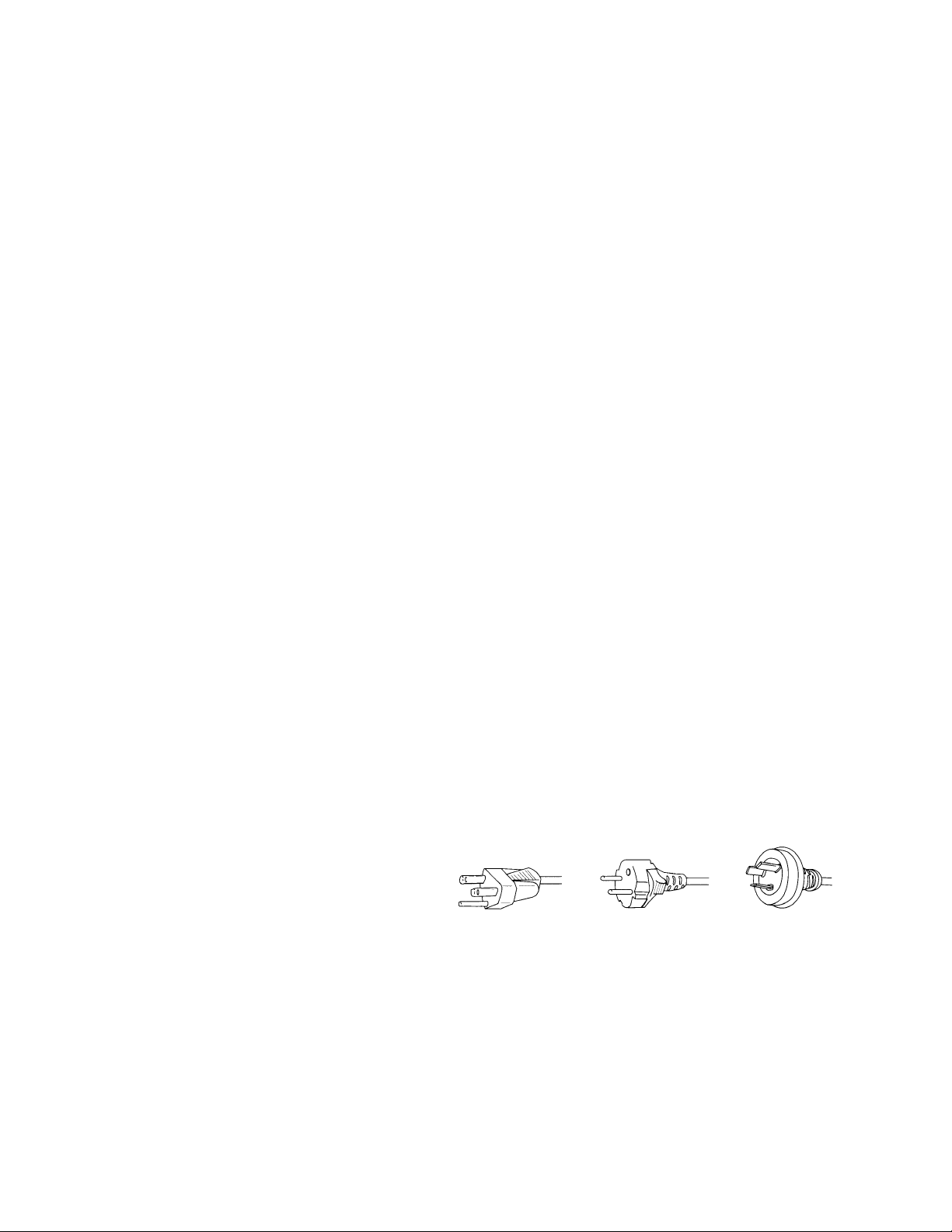
The power supply voltage rating of this unit is AC100-240V, but the attached power cord conforms to the following
power supply voltage. Use only the Power Cord designated by our dealer to ensure Safety and EMC.
When used with other power supply voltages, the power cable must be changed.
Consult your local dealer.
Power Cord
Power supply voltage : AC 100 - 125 V AC 200 - 240 V AC-240V
(SAA TYPE)
- 3 -
Page 5

SPECIFICATIONS
Model : P42HHS10W/E
Power requirement
PDP UNIT
SELECTOR UNIT
Current drain
PDP UNIT
SELECTOR UNIT
Display panel
Screen size 92.2(W) X 52.2(H) [cm]
Aspect ratio 16 : 9
Number of pixels 1,024(H) X 1024(V) pixels
Pixel pitch 0.90mm X 0.51mm
Contrast ratio 1000 : 1
Luminance 1000 cd/m2
Viewing angle Max. 160 degrees
Input/Output Terminals of
PDP unit
DVI input DVI-D terminal (HDCP)
Display frequency Horizontal : 33.75MHz
Digital(optical) audio input
Effective max.
output
Input/Output Terminals of
SELECTOR unit
Video input RCA terminal
S video input
Component video input
Video input (E model)
S video
Digital RGB1 input
110-240V, 50/60Hz
110-240V, 50/60Hz
4.3A-1.8A
0.4A
UB type
36.3(W) X 20.6(H) [inch]
Differential Input 0.5 10%
+ + + +
(RXC , RX0 , RX1 , RX2 )
Vertical : 60Hz
Dot clock : 40.5MHz
Optical Input
-27dB to -14.5dB
Level terminal
10W+10W (L/R), 6
1.0V /75
P-P
S terminal
Y signal : 1.0V /75
P-P
C signal : 0.286V /75P-P
Three RCA terminals
(one system)
Y : 1.0V /75P-P
Pb/B-Y : 0.7V /75P-P
Pr/R-Y : 0.7V /75P-P
SCART terminal
1.0V /75Video
P-P
Y signal : 1.0V /75
C signal : 0.286V /75
G : 0.7V /75RGB
B : 0.7V /75
R : 0.7V /75
P-P
P-P
P-P
P-P
P-P
DVI-D terminal (HDCP)
Differential Input 0.5 10%
(RXC , RX0 , RX1 , RX2 )
+
+ + +
Analog RGB2/
RGB3 input
mD-sub : 15pin(3 row type)
Video : 0.7V /75
P-P
SYNC signal : TTL level
8 memories (each RGB1,2,3)User set mode
Display frequency
Horizontal : 15.63 to 80.0MHz
Vertical : 50.0 to 120Hz
Dot clock : 50MHz Max.
XGA 68MHz
Digital RGB1 output
Analog audio input
DVI-D terminal (HDCP)
Differential Input 0.5 10%
+ + + +
(RXC , RX0 , RX1 , RX2 )
+
Two RCA terminals
(one system)
500mVrms/22K
Digital(optical) audio
+
input
Optical Input
-24dB to -14.5dB
Digital(optical) audio
output
for Display
for audio amp
Color system
Optical Input
-21dB to -15dB
-21dB to -15dB
NTSC/PAL/SECAM/N-PAL/M-PAL
/4.43NTSC/PAL60
Display colors
16.7 million (256 each for R.G.B.)
Outer dimensions
PDP UNIT
Width : 103.7cm (40.8 inch)
Height : 64.2cm (25.3 inch)
Depth : 8.5cm (3.3 inch)
SELECTOR UNIT
Width : 43.0cm (16.9 inch)
Height : 9.5cm (3.7 inch)
Depth : 37.0cm (14.6 inch)
Net weight
PDP UNIT
SELECTOR UNIT
28.5kg
4.5kg
Environment (Operating)
Temperature 0 to 40
Relative humidity 20 to 80%
Pressure 800 to 1,114 hPa
Accessories
PDP UNIT
User's manual
Power cord
Ferrite core (2)
System cable (Video)
System cable (Audio)
SELECTOR UNIT Power cord
Remote controller
Batteries (Type AA x 2)
+
User's manual (only E model)
- 4 -
Page 6

Options
Stand P-TT4200
Wall mounting unit P-WB4200
Hanging unit
Speaker
Standards
0 to 15 mounting angle
P-CT4200
0 to 15 mounting angle
P-SP4200
P-ST4200Speaker stand
P42HHS10WS
P42HHS10ES
P-SU4H10WS
P-SU4H10ES
UL,CSA
Safety:
UL6500 UL6500
C-UL C-UL
EMC: FCC Part15 Class B FCC Part15 Class B
ICES-003 Class B ICES-003 Class B
CE
Safety: EN60065
EMC : EN55022
EN61000-3-2 1995
1998
EN60065
EN55013
EN55020
EN61000-3-3, 1995
EN55024 1998
EN61000-4-2, 1995
EN61000-4-3, 1996
EN61000-4-4, 1995
EN61000-4-5, 1995
EN61000-4-6, 1996
EN61000-4-8, 1993
EN61000-4-11,1994
AS
Safety : IEC60065 IEC60065
EMC : AS/NZS 3548 AS/NZS 1053
2001
1994
- 5 -
Page 7

Model : P42HHA10W/E
Power requirement
110-240V, 50/60Hz
4.4-1.9ACurrent drain
Display panel
UB type
Screen size 92.0(W) X 51.8(H) [cm]
36.2(W) X 20.4(H) [inch]
Aspect ratio 16 : 9
Number of pixels 1,024 (H) X 1024 (V) pixels
Pixel pitch 0.90mm X 0.51mm
Contrast ratio P42HHA10 1000 : 1 (typ.)
Luminance 1000 cd/m (ryp.)
2
Viewing angle Max. 160 degrees
Input Terminals
Video input BNC connector
P-P /75Ω
1.0V
S video input S terminal
Y signal:1.0V
C signal:0.286V
P-P /75Ω
P-P /75Ω
Component Three BNC terminals
video input Y : 1V
P
b /B-Y: 0.7VP-P /75Ω
r /R-Y: 0.7VP-P /75Ω
P
RGB 1 input
24Pin DVI-D (HDCP)
Differential Input 0.5V 10%
(RXC , RX0 , RX1 , RX2 )
P-P /75Ω
+
+ + + +
RGB 2 input mD-sub:15pin (3 row type)
Video : 0.7V
P-P /75Ω
SYNC signal : TTL level
RGB 3 input BNC terminal x 5
R: 0.7V
P-P/75Ω
G: 0.7VP-P/75Ω
B: 0.7VP-P/75Ω
H: TTL level or 0.3VP-P /75Ω
V: TTL level or 0.3VP-P /75Ω
User set mode 8 memories (each RGB1,2,3)
Display frequency Horizontal :15.63 to 80.0MHz
Vertical : 50.0 to 120Hz
Dot clock:50MHz Max
XGA 68MHz Max
RS-232C D-sub 9 pin terminal
Color system
NTSC/PAL/SECAM/N-PAL/M-PAL
/4.43NTSC/PAL60
Display colors
16.7 million (256 each for R.G.B.)
Audio input 2 pin terminals(three system)
Effective max.
500mVrms/22k
Level terminal 20W+20W (L/R), 4
Ω
output
Net weight 28.5kg
Environment (Operating)
Temperature 0 to 40 C
Relative humidity 20 to 80%
Pressure 800 to 1,114 hPa
Accessories User's manual
Remote controller
Batteries (Type AA x 2)
Power cord
Ferrite core (2)
Options
Stand P-TT4200
Wall mounting unit
P-WB4200
mounting angle
mounting angle
Hanging unit
0 to 15
P-CT4200
0 to 15
Speaker P-SP4200
Speaker stand P-ST4200
Standards
P42HHA10W
P42HHA10E
UL,CSA
Safety:
UL6500 UL6500
CSA C22.2 No. CSA C22.2 No.
EMC: FCC Part15 Class A FCC Part15 Class B
ICES-003 Class A ICES-003 Class B
CE
Safety: EN60065 1992
A1 1993
A2 1993
A3 1995
A4 1997
EMC : EN55022 A1/A2
Class A
EN61000-3-2, 1995
EN61000-3-3, 1995
EN55024 1998
EN61000-4-2, 1995
EN61000-4-3, 1996
EN61000-4-4, 1995
EN61000-4-5, 1995
EN61000-4-6, 1996
EN61000-4-8, 1993
Ω
EN61000-4-11,1994
EN60065 1992
A1 1993
A2 1993
A3 1995
A4 1997
EN55022 A1/A2
Class B
EN61000-3-2, 1995
EN61000-3-3, 1995
EN55024 1998
EN61000-4-2, 1995
EN61000-4-3, 1996
EN61000-4-4, 1995
EN61000-4-5, 1995
EN61000-4-6, 1996
EN61000-4-8, 1993
EN61000-4-11, 1994
Dimensions Width : 103.5cm (40.7 inch)
Height: 64.2cm (25.2 inch)
Depth : 8.5 cm ( 3.3 inch)
AS
Safety : I60065 A1/A2/A3/A4 I60065 A1/A2/A3/A4
EMC : AS/NZS 3548 AS/NZS 3548
- 6 -
Page 8
SETTING SIGNALS
This display can store parameter settings for eight additional signals for RGB.
To do this, select the desired signal and follow "RGB MODE ADJUSTMENT" in the manual to adjust the parameters.
When you finish, the settings will be automatically stored.
FACTORY SET SIGNALS (RGB MODE)
Main corresponding signals (RGB mode)
Display (dots x lines)
640 x 480 31.47 59.94 VGA
640 x 480
640 x 480
720 x 400
800 x 600
800 x 600
800 x 600
1024 x 768
1024 x 768
1024 x 768
1024 x 768
1280 x 1024 63.98 60.02 SXGA 60 Hz
1280 x 1024 79.98 75.03 SXGA 75 Hz
1600 x 1200 75.00 60.00
1600 x 1200
848 x 480 31.02 60.00
852 x 480 31.72
1360 x 768
720 x 485 15.73 59.94 60 fields
720 x 575 15.63 50.00 50 fields
* With some input signals, “Out of range” may appear even when the horizontal and vertical frequencies are within their permissible ranges. Make
sure that the vertical frequency of the input signal is 85 Hz or less for SVGA, 75 Hz or less for XVGA/ SXGA , 60 Hz or less for UXGA.
Horizontal frequency (kHz) Vertical frequency (Hz)
37.50 75.00
43.27 85.01
31.47 70.09
37.88 60.32
46.88 75.00 SVGA 75 Hz
53.67 85.06 SVGA 85 Hz
48.36 60.00 XGA 60 Hz
60.02
68.68
106.25 85.00 UXGA 85 Hz
47.71
75.03
84.99
59.97
60.01
VGA 75 Hz
VGA 85 Hz
400 lines
SVGA 60 Hz
XGA 75 Hz
XGA 85 Hz
UXGA 60 Hz
Signal DVD-I
- 7 -
Page 9
FACTORY SET SIGNALS (Component video mode)
Horizontal
frequency (kHz)
15.73 SDTV 480i
15.63 SDTV 576i
31.47 SDTV 480p
31.25 SDTV 576p
45.00 HDTV 720p
37.50 HDTV 720p
33.75 HDTV 1,080i
28.13 HDTV 1,080i
The dedicated graphics card is optional.
In the 800 x 600 and 1,024 x 768 modes, images of reduced size are displayed on the screen, using size reduction and
interpolation. Also note that on-screen information is also displayed in reduced size.
" Out of range" appears if the display receives a signal whose characteristic does not fall within the display's
permissible range.
You can check the input signals with "Information" on the OTHERS Menu screen.
Vertical
frequency (Hz)
59.94
50.00
59.94
50.00
60.00
50.00
60.00
50.00
Signal
FACTORY SET SIGNALS (Video, S-video mode)
Horizontal
frequency (kHz)
15.73 NTSC
15.63 PAL
15.63 SECAM
15.63 PAL 60
15.63 N-PAL
15.73 M-PAL
15.73 4.43 NTSC
Vertical
frequency (Hz)
59.94
50.00
50.00
59.52
50.00
59.95
59.94
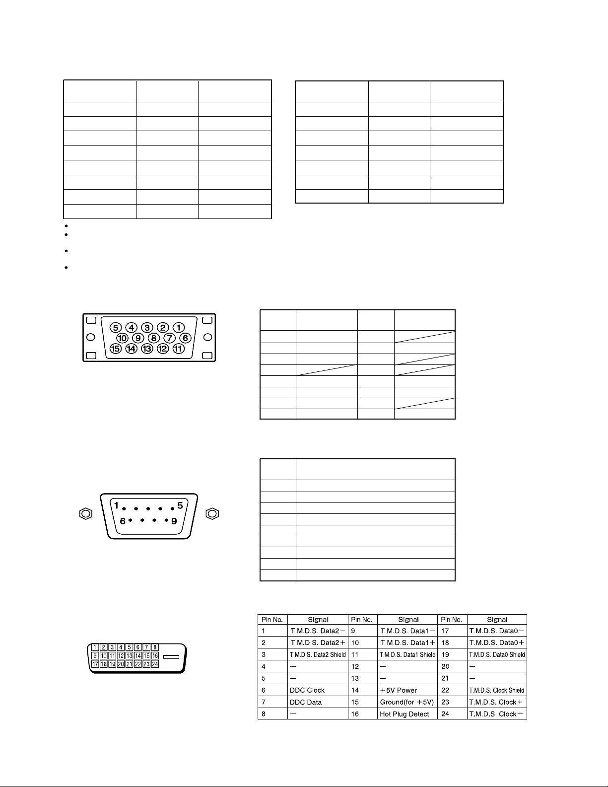
RGB INPUT TERMINAL
Pin No. Input signal Pin No. Input signal
1 Red 9
2 Green 10 Ground
3 Blue 11
∗ The sync switch (TTL/ANALOG switch) is on
the rear of the 13-pin horizontal sync and
14-pin vertical sync terminals.
4
5 Ground 13 Horiz. sync
6 Ground 14 Vert. sync
7 Ground 15
8 Ground
12
Outer side
Ground
Signal
RS-232C INPUT TERMINAL
Pin No.
DVI-D INPUT TERMINAL
Pin No. No. signal
1 DCD (Data Carrier Detect)
2 RD (Receive Data)
3 TD (Transmit Data)
4 DTR (Data Terminal Ready)
5 GND (Ground)
6 DSR (Data Set Ready)
7 RTS (Request To Send)
8 CTS (Clear To Send)
9 RI (Ring Indication)
- 8 -
Page 10
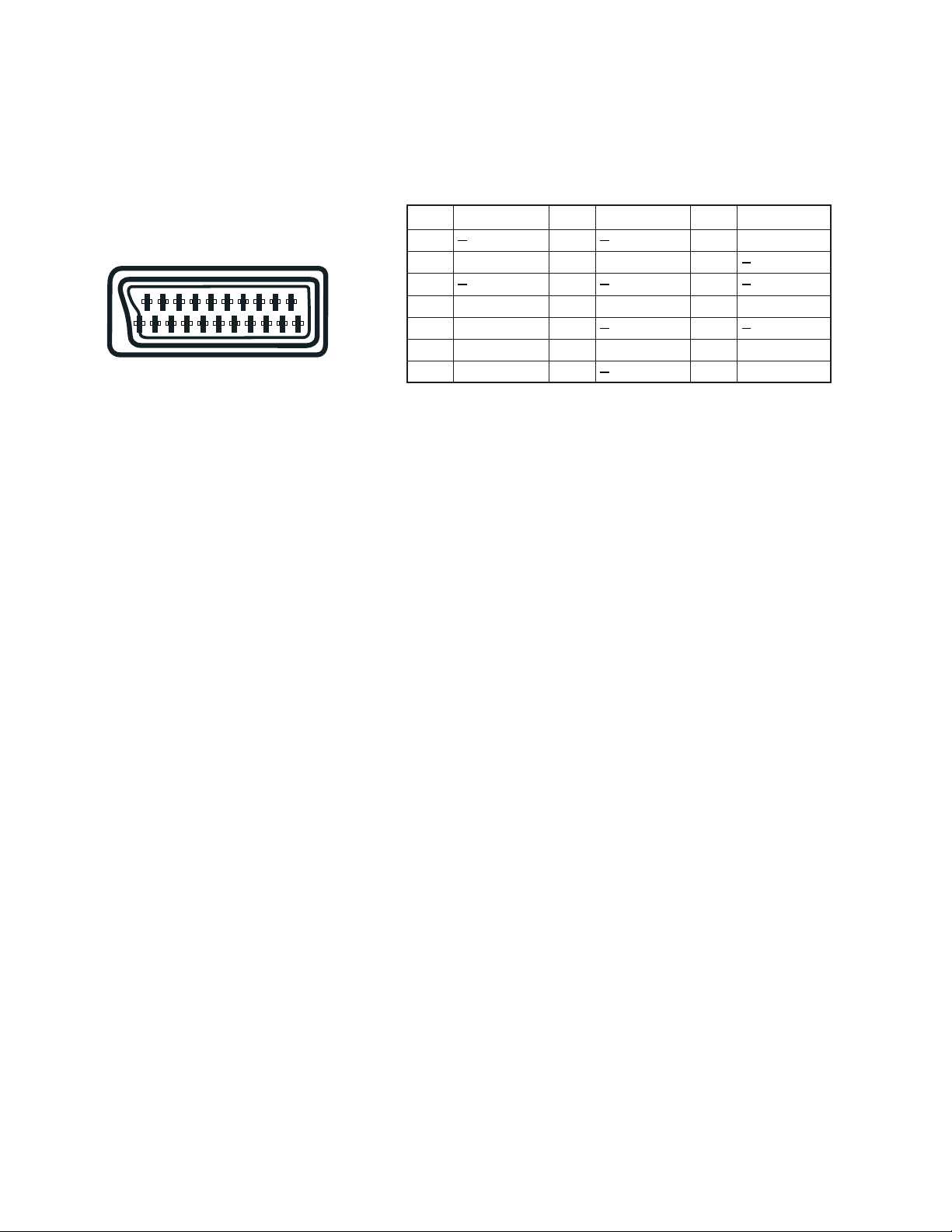
SCART TERMINAL
48121620
26101418
37111519
Pin No.
1
2 Right audio
3
4
5 Blue ground
159131721
6 Left audio
7 Blue
Input Signal
Audio ground
Pin No.
8
9
10
11 Green
12
13 Red ground
14
Input Signal
Green ground
Pin No.
15
16
17
18
19
20
21 Ground
Input Signal
Red/chrominance
Composite video ground
Composite video/Y
- 9 -
Page 11
CONNECTION
Model : P42HHS10W/E
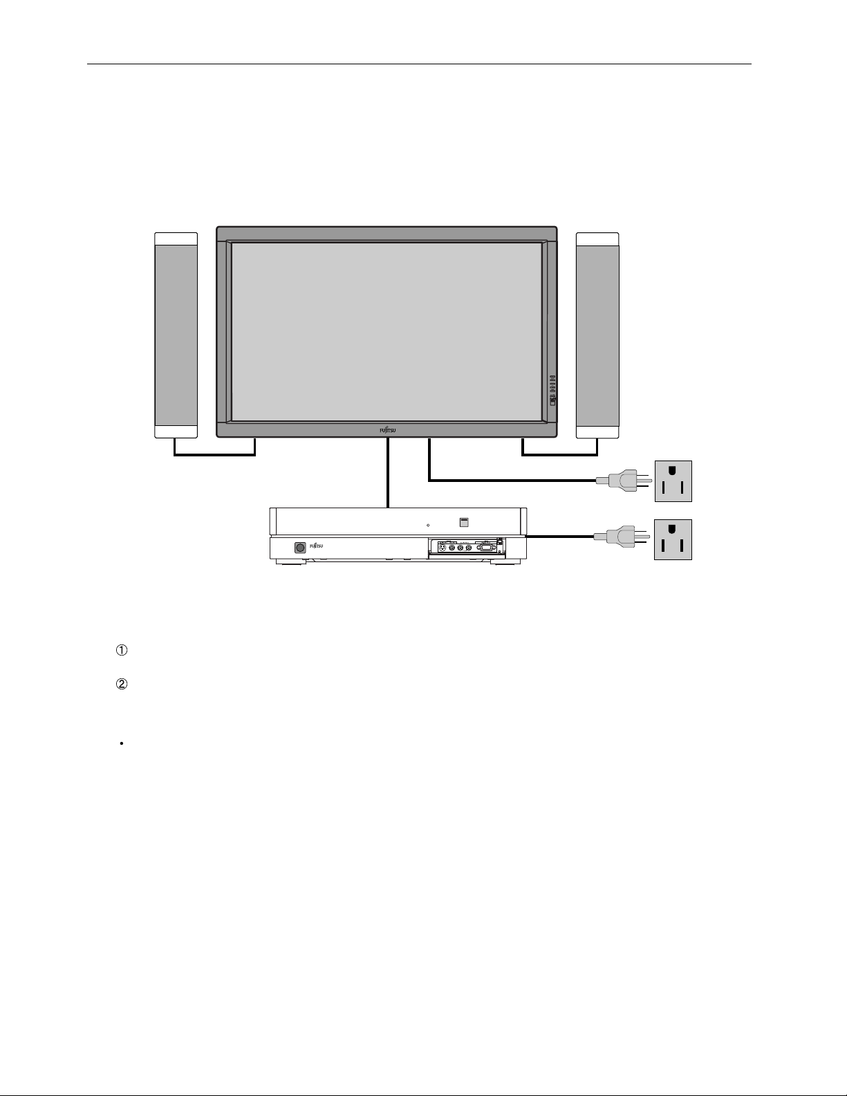
BASIC SYSTEM CONNECTIONS
Display
Selector
Speaker (optional)
3-pin outlet
3-pin outlet
1. Connect the following items to the selector and the display
Selector and display
Connect these two with the provided system connection cable. (For details, see the page on the right.)a
Speakers
For how to connect speakers, see the instructions provided with the speakers.
2. Connecting the power cord
Connect the power plug of the display and selector power cords to a 3-pin outlet.
- 10 -
Page 12
Model : P42HHS10W
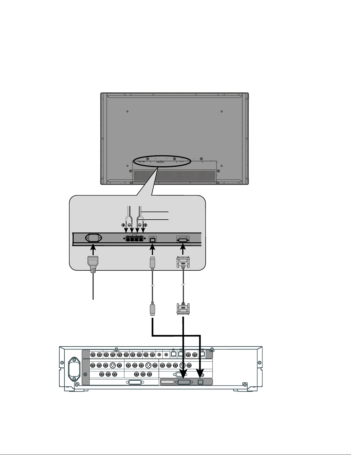
CONNECTING THE DISPLAY AND THE SELECTOR
Rear side of display
Left speaker cable Right speaker cable
Audio
terminal
To AC outlet
VIDEO1 VIDEO2 VIDEO4 VIDEO5 VIDEO6 RGB1 RGB2
AUDIO
INPUT
PICTURE
INPUT
COMPONENT VIDEO
Y PB/C
COMPONENT VIDEO
B PR/CR
Y P
VIDEO1
VIDEO5
B/CB PR/CR
COMPONENT VIDEO
RGB1
DVI
COMPONENT VIDEO
Y PB/C
S
VIDEO2
B PR/CR
VIDEO1
Y PB/C
S
B PR/CR
Red
Black
Display input terminalPower input
Picture
terminal
AUDIO
OUTPUT
VIDEO4
RGB2
DIGITAL
PICTURE AUDIO
DIGITAL1 DIGITAL2
COMPONENT VIDEO
Y PB/C
B PR/CR
mD-sub
DISPLAY OUTPUT
S
Rear side of selector
- 11 -
Page 13
Model : P42HHS10W/E
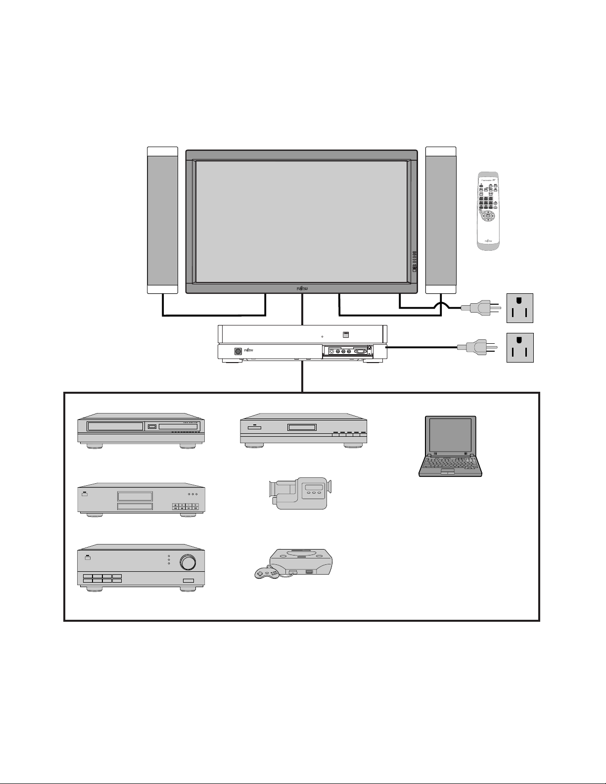
EXAMPLE OF CONNECTION TO EXTERNAL COMPONENTS
Speaker
Display
Selector
Speaker (optional)
Remote
control
VCR
DVD player
Amplifier
Satellite tuner
PC
Video camera
Videogame machine
- 12 -
Page 14
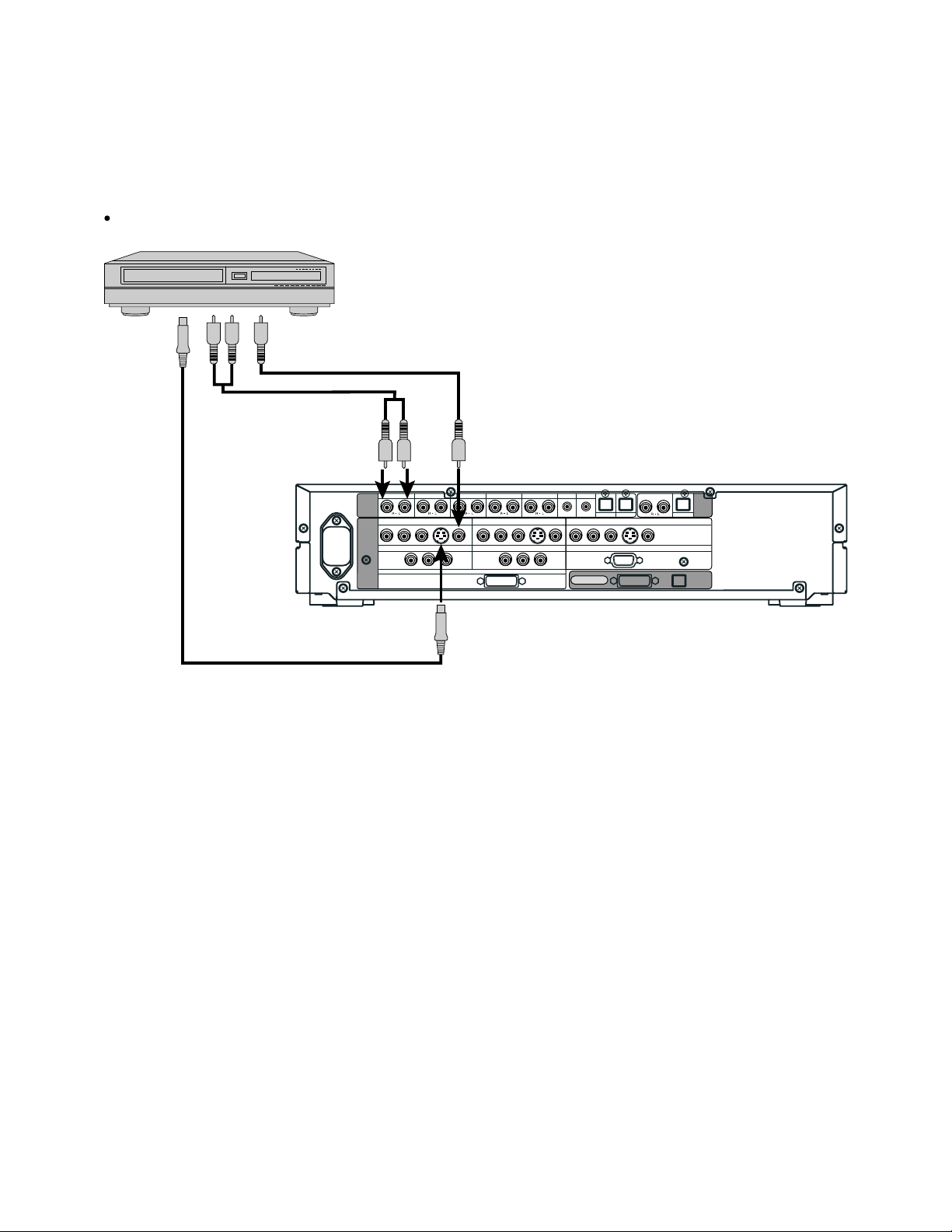
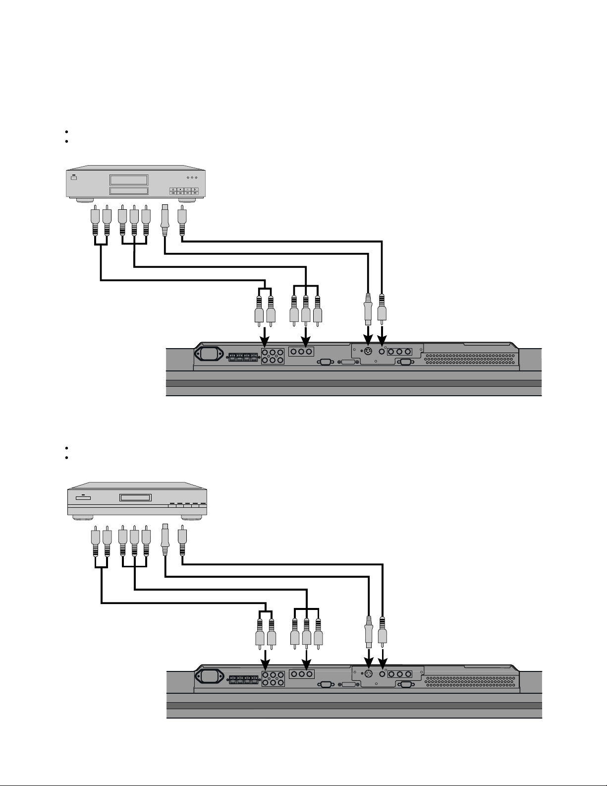
Model : P42HHS10W
VCR
Connect the video signal cable to either the S-video input terminal or the video input terminal.
To S-video
output
To audio outputs
To video output
To audio inputs
To S-video input
To video input
VIDEO1 VIDEO2 VIDEO4 VIDEO5 VIDEO6 RGB1 RGB2
AUDIO
INPUT
PICTURE
INPUT
COMPONENT VIDEO
Y PB/C
COMPONENT VIDEO
B PR/CR
Y P
VIDEO1
VIDEO5
B/CB PR/CR
S
RGB1
COMPONENT VIDEO
DVI
COMPONENT VIDEO
Y PB/C
VIDEO2
B PR/CR
VIDEO1
Y PB/C
Rear side of selector
S
B PR/CR
DIGITAL1 DIGITAL2
COMPONENT VIDEO
Y PB/C
B PR/CR
mD-sub
DISPLAY OUTPUT
S
VIDEO4
RGB2
DIGITAL
PICTURE AUDIO
AUDIO
OUTPUT
- 13 -
Page 15
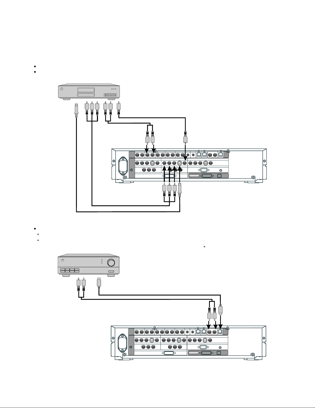
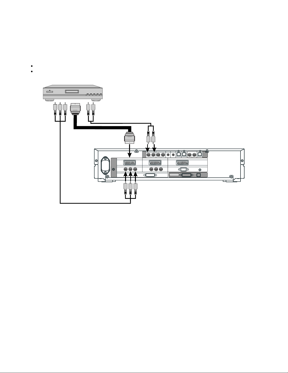
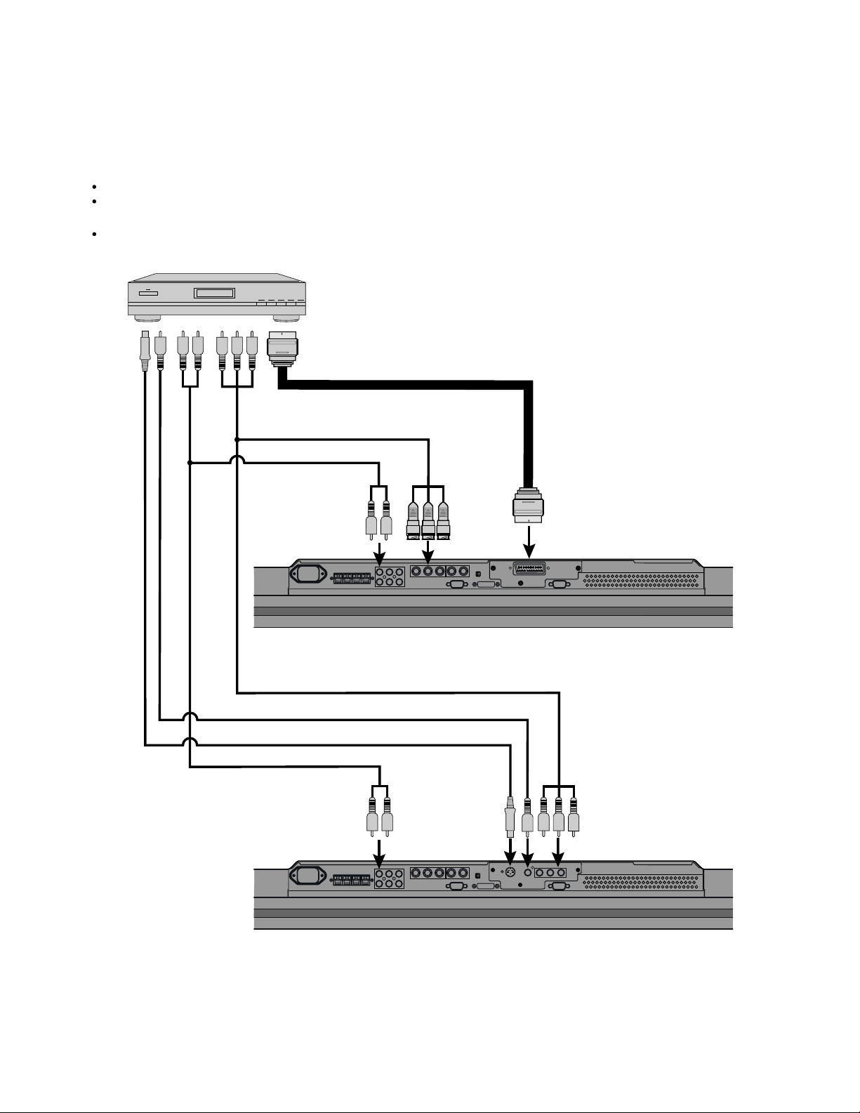
DVD PLAYER
Connect the video signal cable to the component video input terminal, S-video input terminal, or the video input terminal.
If the component to be connected is equipped with component video output terminal, it is recommended to connect to the
component video terminal.
To video output
To S-video
output
To audio outputs
To component
video output
VIDEO1 VIDEO2 VIDEO4 VIDEO5 VIDEO6 RGB1 RGB2
AUDIO
INPUT
COMPONENT VIDEO
Y PB/C
PICTURE
INPUT
COMPONENT VIDEO
To audio
inputs To video input
B PR/CR
Y P
VIDEO1
VIDEO5
S
B/CB PR/CR
COMPONENT VIDEO
RGB1
DVI
COMPONENT VIDEO
Y PB/C
B PR/CR
Y PB/C
VIDEO2
S
VIDEO1
B PR/CR
COMPONENT VIDEO
Y PB/C
mD-sub
DISPLAY OUTPUT
DIGITAL1 DIGITAL2
B PR/CR
VIDEO4
S
RGB2
Rear side of selector
To component video input
To S-video input
AMPLIFIER
Connect the audio signal cable to either the digital output or the analog audio output.
The signal input as digital input is not output as analog audio.
The digital audio input terminal on the display complies with a sampling frequency of 48 kHz.
In the case of outputs with another frequency, connect to an audio system (amplifier) .
PICTURE
AUDIO
OUTPUT
DIGITAL
AUDIO
To digital audio input
To analog audio input
To analog audio output To digital audio output
VIDEO1 VIDEO2 VIDEO4 VIDEO5 VIDEO6 RGB1 RGB2
AUDIO
INPUT
PICTURE
INPUT
COMPONENT VIDEO
Y PB/C
COMPONENT VIDEO
B PR/CR
Y P
VIDEO1
VIDEO5
S
B/CB PR/CR
RGB1
DVI
COMPONENT VIDEO
Y PB/C
COMPONENT VIDEO
VIDEO2
B PR/CR
VIDEO1
Y PB/C
Rear side of selector
- 14 -
S
B PR/CR
COMPONENT VIDEO
Y PB/C
mD-sub
DISPLAY OUTPUT
DIGITAL1 DIGITAL2
B PR/CR
S
VIDEO4
RGB2
DIGITAL
PICTURE AUDIO
AUDIO
OUTPUT
Page 16
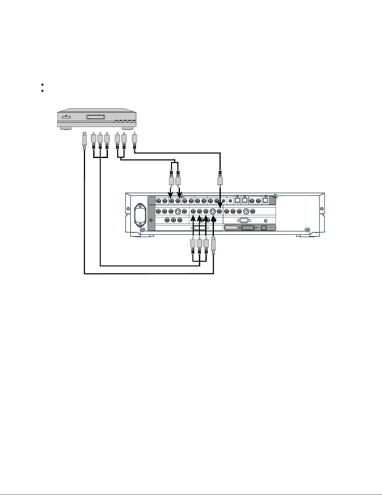
SATELLITE TUNER
Connect the video signal cable to the component video input terminal, S-video input terminal, or the video input terminal.
If the component to be connected is equipped with component video output terminal, it is recommended to connect to the
component video terminal.
To S-video
output
To audio outputs
To component
video output
To component video input
To video output
To audio
inputs
VIDEO1 VIDEO2 VIDEO4 VIDEO5 VIDEO6 RGB1 RGB2
AUDIO
INPUT
PICTURE
INPUT
COMPONENT VIDEO
Y PB/C
COMPONENT VIDEO
B PR/CR
Y P
VIDEO1
VIDEO5
B/CB PR/CR
RGB1
DVI
COMPONENT VIDEO
Y PB/C
COMPONENT VIDEO
B PR/CR
Y PB/C
S
VIDEO2
S
VIDEO1
B PR/CR
To S-video input
To video input
DIGITAL1 DIGITAL2
VIDEO4
COMPONENT VIDEO
S
Y PB/C
B PR/CR
RGB2
mD-sub
DISPLAY OUTPUT
PICTURE
DIGITAL
AUDIO
OUTPUT
AUDIO
- 15 -
Page 17
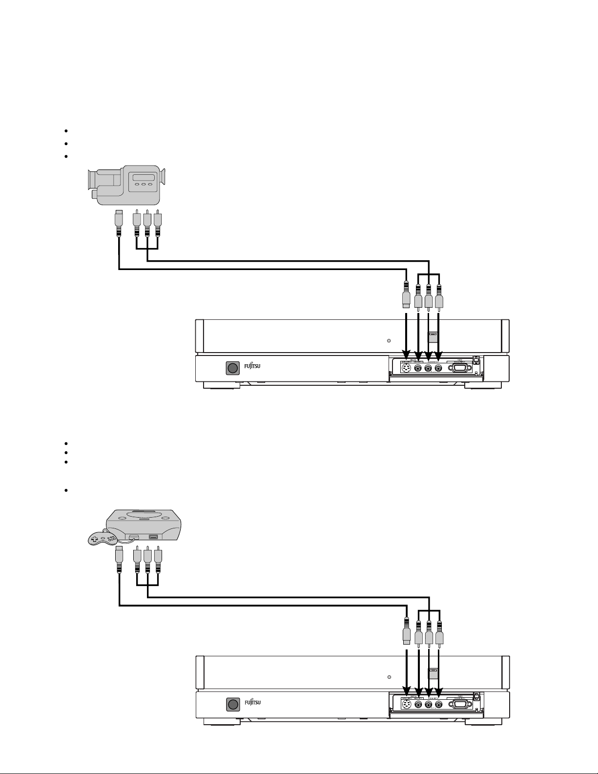
Model : P42HHS10W/E
VIDEO CAMERA
A video camera can conveniently be connected to the Video 3 input on the front side.
Connect the video signal cable to either the S-video input terminal or the video input terminal.
If the unit to be connected is equipped with S-video output terminal, it is recommended to connect to the S-video terminal.
To video and audio outputs
To S-video output
To video and audio inputs
To S-video input
VIDEOGAME MACHINE
As the connecting cable differs with videogame machines, please consult the instructions for your videogame machine.
Connect the video signal cable to either the S-video input terminal or the video input terminal.
Ensure that the same image (pattern) is not displayed on the screen for an extended period. If the same image is displayed on the
screen for an extended period, the brightness of that part of the screen may change and image burn-in may leave
an after-image on the screen.
If the videogame machine to be connected is equipped with S-video output terminal, it is recommended to connect to the
S-video terminal.
To S-video output
To video and audio outputs
To video and audio inputs
To S-video input
Front side of selector
- 16 -
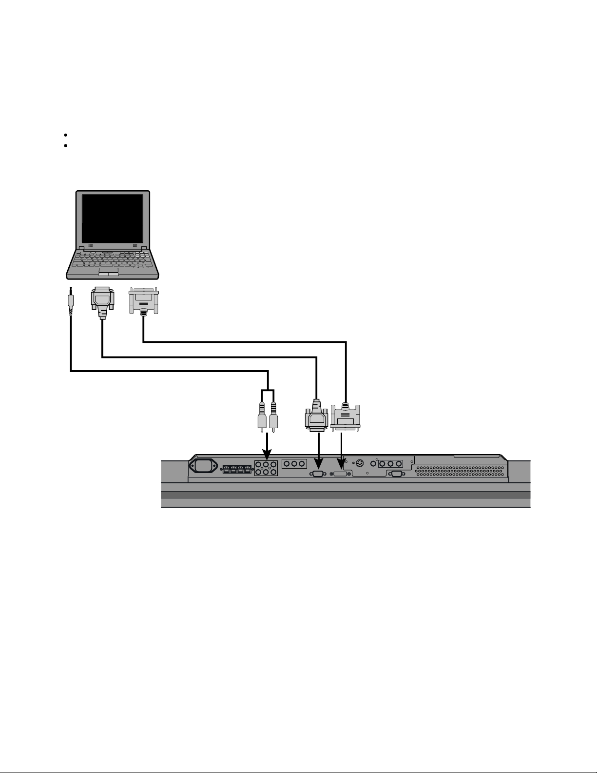
Page 18
Model : P42HHS10W
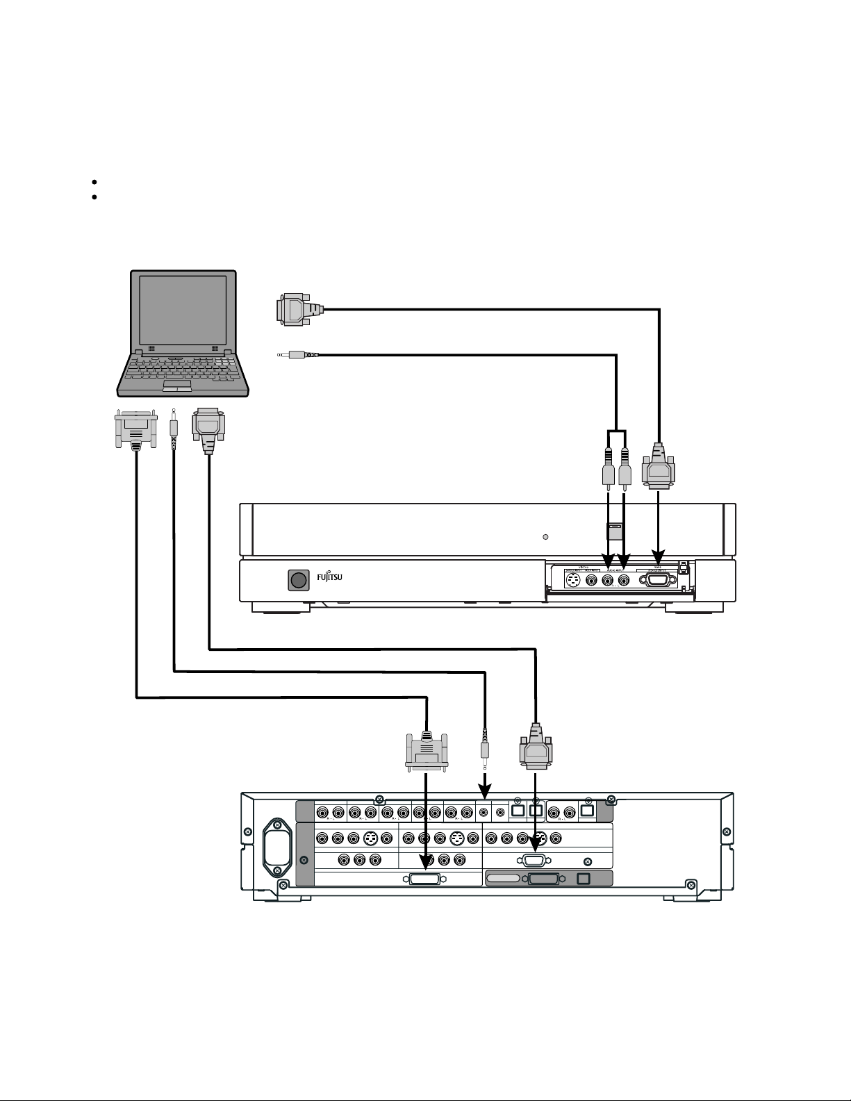
PC
As the cable for connecting a PC differs with the PC model, please consult your dealer for information on the right cable to purchase.
The PC can be connected to either the front side or the rear side, whichever is most convenient.
To RGB output (mD-sub)
To audio output
When connecting to the front side of the selector
To RGB output (mD-sub)
To audio output To audio
To RGB output (DVI-D)
To RGB1 input
(DVI-D)
VIDEO1 VIDEO2 VIDEO4 VIDEO5 VIDEO6 RGB1 RGB2
AUDIO
INPUT
PICTURE
INPUT
COMPONENT VIDEO
Y PB/C
COMPONENT VIDEO
B PR/CR
Y P
VIDEO1
VIDEO5
S
B/CB PR/CR
RGB1
Y PB/C
COMPONENT VIDEO
DVI
COMPONENT VIDEO
B PR/CR
Y PB/C
input
VIDEO2
VIDEO1
B PR/CR
To audio input (mD-sub)
To RGB3 input
To RGB2 input
(mD-sub)
AUDIO
OUTPUT
VIDEO4
RGB2
DIGITAL
PICTURE AUDIO
DIGITAL1 DIGITAL2
S
COMPONENT VIDEO
Y PB/C
B PR/CR
mD-sub
DISPLAY OUTPUT
S
When connecting to the rear side of the selector
- 17 -
Page 19
Model : P42HHS10E
Left speaker cable Right speaker cable
Rear side of display
To AC outlet
SCART SCARTSCART
PICTURE
INPUT
COMPONENT VIDEO
Y P
VIDEO1
VIDEO5
B/CB PR/CR
Audio
terminal
VIDEO5 VIDEO6 RGB1 RGB2
AUDIO
INPUT
COMPONENT VIDEO
Y PB/C
RGB1
DVI
VIDEO2
VIDEO1
B PR/CR
Red
Black
Display input terminalPower input
Picture
terminal
AUDIO
OUTPUT
VIDEO4
RGB2
DIGITAL
PICTURE AUDIO
DIGITAL1 DIGITAL2
mD-sub
DISPLAY OUTPUT
Rear side of selector
- 18 -
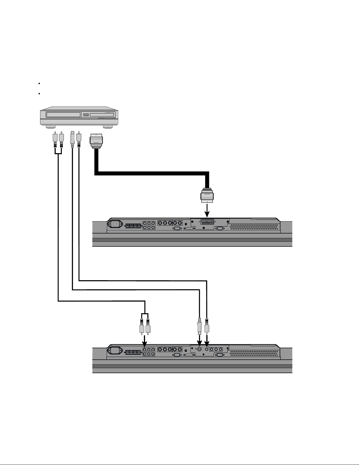
Page 20
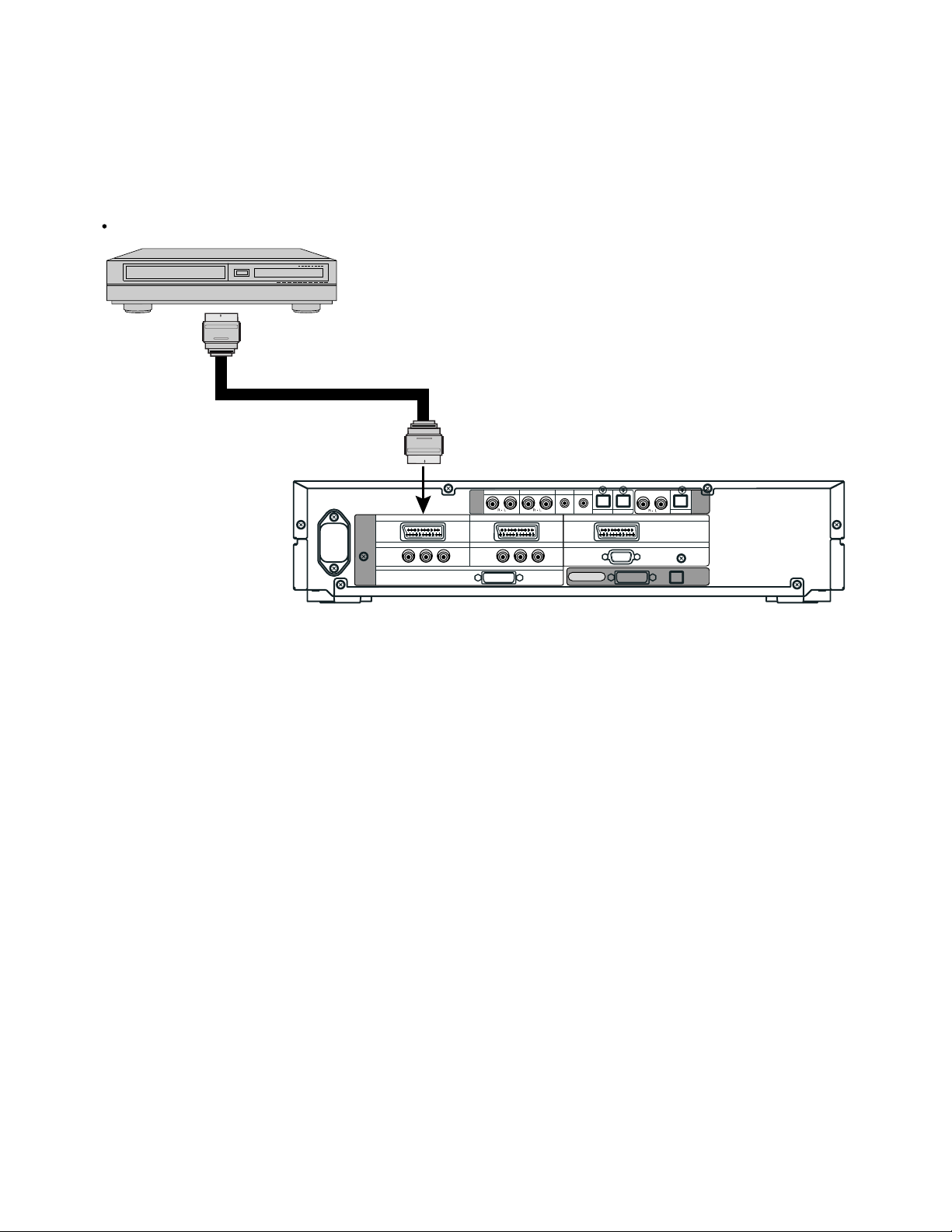
VCR
Connect the video signal cable to the SCART terminal.
To SCART output
To SCART input
VIDEO1
SCART SCARTSCART
PICTURE
INPUT
COMPONENT VIDEO
VIDEO5
Y P
B/CB PR/CR
VIDEO5 VIDEO6 RGB1 RGB2
AUDIO
INPUT
COMPONENT VIDEO
Y PB/C
RGB1
DVI
VIDEO2
VIDEO1
B PR/CR
DIGITAL1 DIGITAL2
mD-sub
DISPLAY OUTPUT
VIDEO4
RGB2
PICTURE AUDIO
Rear side of selector
DIGITAL
AUDIO
OUTPUT
- 19 -
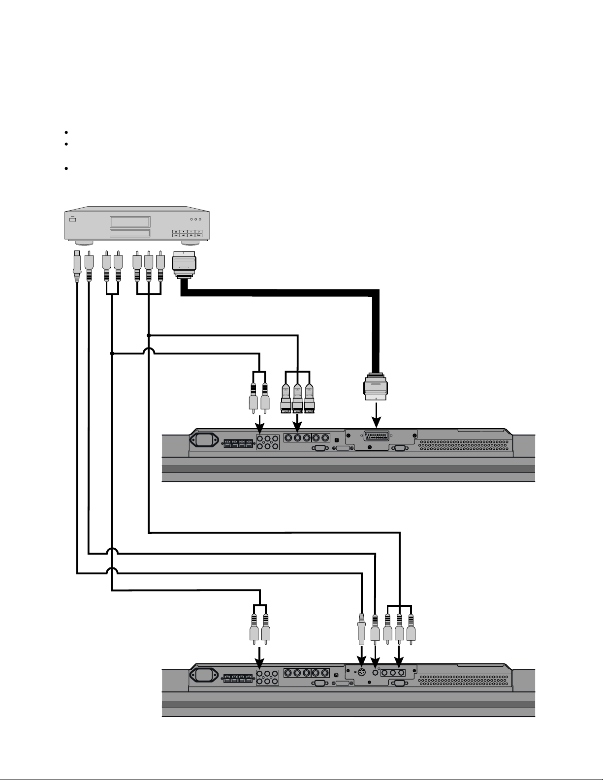
Page 21
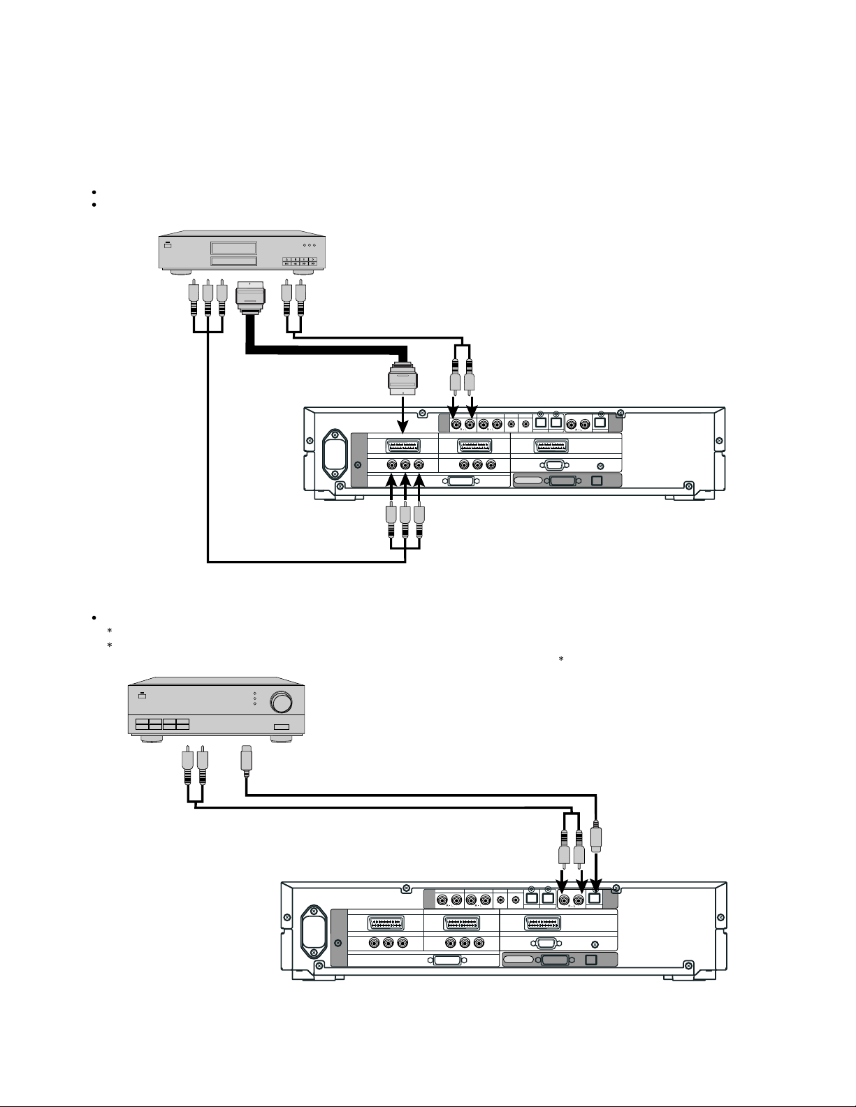
DVD PLAYER
Connect the video signal cable to either the component video terminal or the SCART terminal.
If the component to be connected is equipped with component video output terminal, it is recommended to connect to the
component video terminal.
To audio outputs
To SCART output
To component video
output
To SCART input
PICTURE
INPUT
COMPONENT VIDEO
To component
video input
VIDEO1
SCART SCARTSCART
VIDEO5
B/CB PR/CR
Y P
RGB1
DVI
To audio inputs
VIDEO5 VIDEO6 RGB1 RGB2
AUDIO
INPUT
COMPONENT VIDEO
VIDEO2
VIDEO1
Y PB/C
B PR/CR
mD-sub
DISPLAY OUTPUT
DIGITAL1 DIGITAL2
VIDEO4
Rear side of selector
RGB2
DIGITAL
PICTURE AUDIO
AUDIO
OUTPUT
AMPLIFIER
Connect the audio signal cable to either the digital output or the analog audio output.
The signal input as digital input is not output as analog audio.
The digital audio input terminal on the display complies with a sampling frequency of 48 kHz.
In the case of outputs with another frequency, connect to an audio system (amplifier) .
To digital audio input
To analog audio input
To analog audio output To digital audio output
VIDEO5 VIDEO6 RGB1 RGB2
AUDIO
SCART SCARTSCART
PICTURE
INPUT
COMPONENT VIDEO
Y P
VIDEO1
VIDEO5
B/CB PR/CR
INPUT
VIDEO2
VIDEO1
COMPONENT VIDEO
Y PB/C
RGB1
DVI
B PR/CR
Rear side of selector
mD-sub
DISPLAY OUTPUT
DIGITAL1 DIGITAL2
VIDEO4
RGB2
DIGITAL
PICTURE AUDIO
AUDIO
OUTPUT
- 20 -
Page 22
SATELLITE TUNER
Connect the video signal cable to either the component video terminal or the SCART terminal.
If the component to be connected is equipped with component video output terminal, it is recommended to connect to the
component video terminal.
To audio outputs
To SCART output
To component video
output
To To audio inputs
SCART input
VIDEO5 VIDEO6 RGB1 RGB2
AUDIO
SCART SCARTSCART
PICTURE
INPUT
COMPONENT VIDEO
Y P
VIDEO1
VIDEO5
B/CB PR/CR
RGB1
DVI
INPUT
COMPONENT VIDEO
VIDEO2
VIDEO1
Y PB/C
B PR/CR
DIGITAL1 DIGITAL2
mD-sub
DISPLAY OUTPUT
Rear side of selector
VIDEO4
RGB2
DIGITAL
PICTURE AUDIO
AUDIO
OUTPUT
To component
video input
- 21 -
Page 23
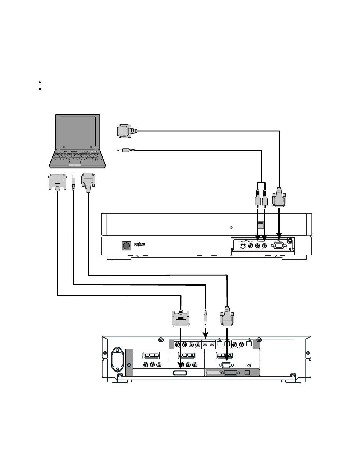
PC
As the cable for connecting a PC differs with the PC model, please consult your dealer for information on the right cable to purchase.
The PC can be connected to either the front side or the rear side, whichever is most convenient.
To RGB output (mD-sub)
To audio output
To RGB3 input
To audio input (mD-sub)
When connecting to the front side of the selector
To RGB output (mD-sub)
To audio output To audio
To RGB output (DVI-D)
To RGB1 input To RGB2 input
(DVI-D) (mD-sub)
VIDEO1
SCART SCARTSCART
PICTURE
INPUT
COMPONENT VIDEO
Y P
VIDEO5
B/CB PR/CR
RGB1
When connecting to the rear side of the selector
input
VIDEO5 VIDEO6 RGB1 RGB2
AUDIO
INPUT
VIDEO2
VIDEO1
COMPONENT VIDEO
Y PB/CB PR/CR
DVI
mD-sub
DISPLAY OUTPUT
DIGITAL1 DIGITAL2
VIDEO4
RGB2
DIGITAL
PICTURE AUDIO
AUDIO
OUTPUT
- 22 -
Page 24
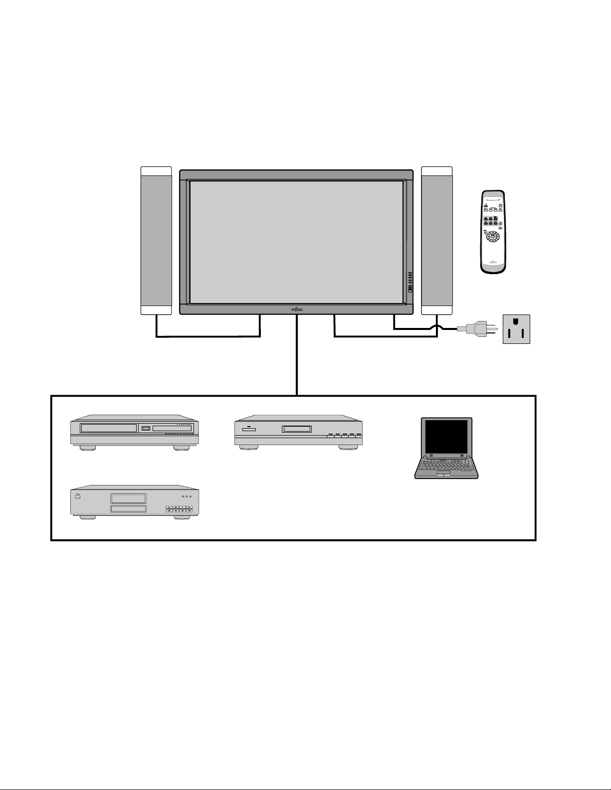
Model : P42HHA10W/E
EXAMPLE OF CONNECTION TO EXTERNAL COMPONENTS
Speaker
Display
Speaker (optional)
Remote
control
VCR
DVD player
Satellite tuner
PC
- 23 -
Page 25
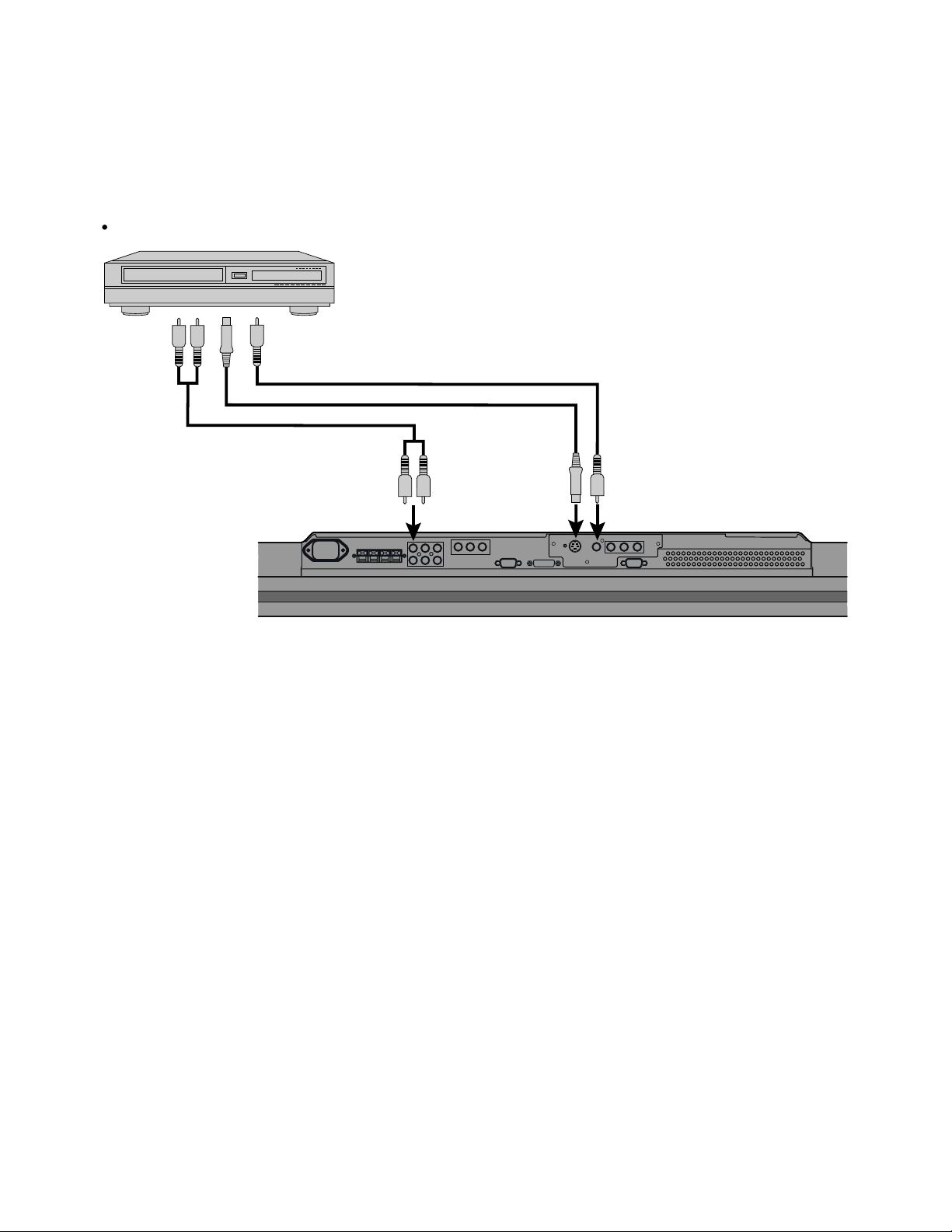
Model : P42HHA10W
VCR
Connect the video signal cable to either the S-video input terminal or the video input terminal.
To audio
outputs
To video output
To S-video output
To audio inputs
To S-video input To video input
Bottom of Display (Ex.: P42VHA10)
- 24 -
Page 26
DVD PLAYER
Connect the video signal cable to the component video input terminal, S-video input terminal, or the video input terminal.
If the component to be connected is equipped with component video output terminal, it is recommended to connect to the
component video terminal.
To video output
To audio
outputs
To component video output
To S-video output
To
component
video input
To audio
inputs
To S-video
input
To video input
Bottom of Display (Ex.: P42VHA10)
SATELLITE TUNER
Connect the video signal cable to the component video input terminal, S-video input terminal, or the video input terminal.
If the component to be connected is equipped with component video output terminal, it is recommended to connect to the
component video terminal.
To video output
To S-video output
To component video output
To audio outputs
To audio
inputs
To S-video
input
To video input
Bottom of Display (Ex.: P42VHA10)
- 25 -
Page 27
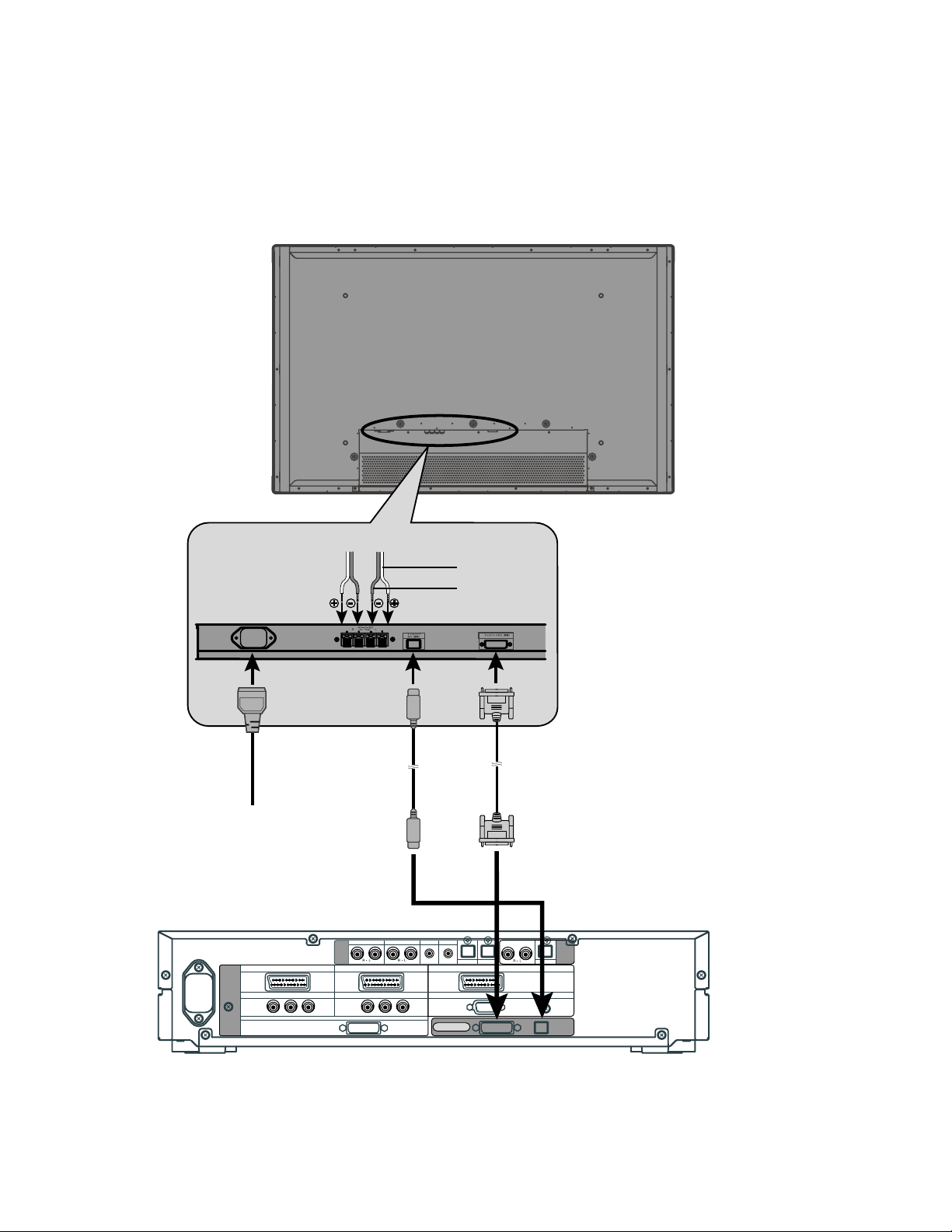
PC
As the cable for connecting a PC differs with the PC model, please consult your dealer for information on the right cable to purchase.
The PC can be connected to either the front side or the rear side, whichever is most convenient.
To RGB output (DVI-D)
To RGB output (mD-sub)
To audio output
To RGB2
input
(mD-sub)
To audio
input
To RGB1 input
(DVI-D)
Bottom of Display (Ex.: P42VHA10)
- 26 -
Page 28
Model : P42HHA10E
VCR
Connect the video signal cable to the SCART terminal. (When the P-TE1000E is installed.)
Connect the video signal to either the S-video input terminal or the video input terminal. (When the P-TE1010E is installed.)
To SCART output
To SCART input
To video output
To S-video output
To audio output
An example of the underside of the display
(with the P-TE1000E installed in the P42VHA10)
To video inputTo S-video inputTo audio input
An example of the underside of the display
(with the P-TE1010E installed in the P42VHA10)
- 27 -
Page 29
DVD PLAYER
Connect the video signal cable to either the component video terminal or the SCART terminal. (When the P-TE1000E is installed.)
Connect the video signal cable to the component video input terminal, S-video input terminal, or the
video input terminal. (When the P-TE1010E is installed.)
If the component to be connected is equipped with component video output terminal, it is recommended to connect to the
component video terminal.
To SCART output
To component video output
To audio output
To component
video input
To SCART input
To audio input
To component video output
To video output
To S-video output
To audio output
An example of the underside of the display
(with the P-TE1000E installed in the P42VHA10)
To audio input To S-video input
An example of the underside of the display
(with the P-TE1010E installed in the P42VHA10)
- 28 -
To component
video input
Page 30
SATELLITE TUNER
Connect the video signal cable to either the component video terminal or the SCART terminal. (When the P-TE1000E is installed.)
Connect the video signal cable to the component video input terminal, S-video input terminal, or the
video input terminal. (When the P-TE1010E is installed.)
If the component to be connected is equipped with component video output terminal, it is recommended to connect to the
component video terminal.
To SCART output
To component video output
To audio output
To audio input
To component
video input
To SCART input
To component video output
To video output
To S-video output
To audio output
An example of the underside of the display
(with the P-TE1000E installed in the P42VHA10)
To video input
To audio input
To S-video input
An example of the underside of the display
(with the P-TE1010E installed in the P42VHA10)
To component
video input
- 29 -
Page 31

PC
As the cable for connecting a PC differs with the PC model, please consult your dealer for information on the right cable to purchase.
The PC can be connected to either the front side or the rear side, whichever is most convenient.
To RGB output (DVI-D)
To RGB output (mD-sub)
To audio output
To RGB2
input
(mD-sub)
To audio input
To RGB1 input
(DVI-D)
An example of the underside of the display
(with the P-TE1000E installed in the P42VHA10)
- 30 -
Page 32

EXAMPLE OF CONNECTION TO EXTERNAL COMPONENTS
Speaker
Display
Speaker (optional)
Remote
control
PC
- 31 -
Page 33

PC
As the cable for connecting a PC differs with the PC model, please consult your dealer for information on the right cable to purchase.
The PC can be connected to either the front side or the rear side, whichever is most convenient.
To RGB output (DVI-D)
To RGB output (mD-sub)
To audio output
To RGB2
input
(mD-sub)
To audio input To RGB1 input
(DVI-D)
Bottom of Display (Ex.: P42VHA10)
- 32 -
Page 34

PART NAMES AND FUNCTIONS
DISPLAY SECTION – FRONT
(Right section)
Power indicator lamp
This lamp shows the state of the power supply.
Lit (red): Stand-by
Lit (green): Power ON
Lit (orange): Power saving (DPMS: Power saving
function) mode ON
Flashing (red): Malfunction (Flashes differently depending
on the type of malfunction.)
Remote control signal receiver
Receives signals from the remote control.
Input mode selector button
Input mode selector button
Switches between picture input modes.
VOL + button
VOL - button
Adjusts the sound volume.
Wide screen selector button [WIDE]
Switches the screen over to a desired wide screen.
ON/OFF button
Turns the power "ON" and "OFF (standby state)".
[MODE]
[MODE]
Control Panel (Right side of display)
- 33 -
Page 35

Model : P42HHS10W/E
DISPLAY SECTION – LOWER PART
power switch
When pressed while in the "OFF" state, the power indicator lamp lights and the display is placed in the "ON " state, and the
power can be turned "ON" or "OFF" by the remotye control or on the control panel of the display. When passed while in
the "ON " state, the power indicator lamp goes out and the display is placed in the "OFF" state.
Display input (picture) terminal
Connect this terminal to the display output terminal on the tuner using the special cable provided.
Display input (audio) terminal
Connect this terminal to the display output terminal on the tuner using the special cable provided.
External speaker output terminal (EXT SP)
Connect this terminal to the optionally available speaker.
When connecting a cable, attach a ferrite core to the cable.
*See the speakerer instruction manual for more information.
Power input terminal
Connect this terminal to the power cable supplied with the display.
- 34 -
Page 36

Model : P42HHA10W
DISPLAY SECTION – LOWER PART
Bottom
/I power switch
When pressed while in the "OFF" state, the power indicator lamp lights and the display is placed in the "ON
can be turned "ON" or "OFF" by the remote control or on the control panel of the display. When pressed while in the "ON
the power indicator lamp goes out and the display is placed in the "OFF" state where power is still partly supplied.
RS-232C terminal (RS-232C)
This terminal is provided for you to control the display from the PC. Connect it to the RS-232C terminal on the PC.
When connecting a cable, attach a ferrite core to the cable.
RGB1 input terminal (RGB1 INPUT/DVI-D)
Connect this terminal to the PC's display (digital RGB) output terminal.
*The connection cable No.88741-8000 made by molex Inc. is recommanded.
RGB2 input terminal (RGB2 INPUT/mD-sub)
Connect this terminal to the PC's display (analog RGB) output terminal or decoder (digital broadcast tuner, etc.) output terminal.
Power input terminal
Connect this terminal to the power cable supplied with the display.
When connecting a cable, attach a ferrite core to the cable.
External speaker output terminal (EXT SP)
Connect this terminal to the optionally available speaker.
When connecting a cable, attach a ferrite core to the cable.
*See the speaker instruction manual for more information.
Audio1 input terminal (AUDIO1 INPUT)
Audio2 input terminal (AUDIO2 INPUT)
Audio3 input terminal (AUDIO3 INPUT)
Connect this terminal to the sound output terminal of your VCR, etc.
Component video input terminal (VIDEO3 INPUT)
Connect this terminal to the component video output (color difference output) terminal of your HDTV unit or DVD player.
S-Video input terminal (VIDEO2 INPUT)
Connect this terminal to the S-video output terminal of your VCR.
Video input terminal (VIDEO1 INPUT)
Connect this terminal to the video output terminal of your VCR.
Component video input terminal (VIDEO4 INPUT)
Connect this terminal to the component video output (color difference output) terminal of your HDTV unit or DVD player.
" state, and the power
" state,
- 35 -
Page 37

Model : P42HHA10E
DISPLAY SECTION - LOWER PART
Bottom
Videoboard
P-TE1000E type P-TE1010E type
/I power switch
When pressed while in the "OFF" state, the power indicator lamp lights and the display is placed in the "ON
"ON" or "OFF" by the remote control or on the control panel of the display. When pressed while in the "ON
out and the display is placed in the "OFF" state where power is still partly supplied.
RS-232C terminal (RS-232C)
This terminal is provided for you to control the display from the PC. Connect it to the RS-232C terminal on the PC.
When connecting a cable, attach a ferrite core to the cable.
RGB1 input terminal (RGB1 INPUT/DVI-D)
Connect this terminal to the PC's display (digital RGB) output terminal.
*The connection cable No.88741-8000 made by molex Inc. is recommanded.
RGB2 input terminal (RGB2 INPUT/mD-sub)
Connect this terminal to the PC's display (analog RGB) output terminal or decoder (digital broadcast tuner, etc.) output terminal.
Power input terminal
Connect this terminal to the power cable supplied with the display.
When connecting a cable, attach a ferrite core to the cable.
External speaker output terminal (EXT SP)
Connect this terminal to the optionally available speaker.
When connecting a cable, attach a ferrite core to the cable.
*See the speaker instruction manual for more information.
Audio3 input terminal (AUDIO3 INPUT)
Audio2 input terminal (AUDIO2 INPUT)
Audio1 input terminal (AUDIO1 INPUT)
Connect this terminal to the sound output terminal of your VCR, etc.
+ RGB3 input terminal (RGB3 INPUT/BNC)
Connect this terminal to the PC's display (analog RGB) output terminal or decoder (digital broadcast tuner,etc.) output terminal.
*When RGB3 input terminal is connected, Comp.video mode is not available.
Component video input terminal (VIDEO4 INPUT)
Connect this terminal to the component video output (colour difference output) terminal of your HDTV unit or DVD player.
*When Comp.video input terminal is connected, RGB3 mode is not available.
RGB3 synchronization switch (SYNC SW TTL/ANALOG (75 ))
This switch is used to terminate horizontal (H) terminal and vertical (V) terminal, out of RGB3 input terminals, with 75 .
TTL : Does not terminate.
ANALOG (75 ): Terminates.
Video1 input terminal (VIDEO1 INPUT/P-TE1000E)
Connect this terminal to the SCART terminal of your VCR or DVD, etc.
S-Video input terminal (VIDEO2 INPUT/P-TE1010E)
Connect this terminal to the S-video output terminal of your VCR.
Video input terminal (VIDEO1 INPUT/P-TE1010E)
Connect this terminal to the video output terminal of your VCR.
Component video input terminal (VIDEO3 INPUT/P-TE1010E)
Connect this terminal to the component video output (colour difference output) terminal of your HDTV unit or DVD player.
" state, and the power can be turned
" state, the power indicator lamp goes
- 36 -
Page 38

DISPLAY SECTION – LOWER PART
Bottom
/I power switch
When pressed while in the "OFF" state, the power indicator lamp lights and the display is placed in the "ON
can be turned "ON" or "OFF" by the remote control or on the control panel of the display. When pressed while in the "ON
the power indicator lamp goes out and the display is placed in the "OFF" state where power is still partly supplied.
RS-232C terminal (RS-232C)
This terminal is provided for you to control the display from the PC. Connect it to the RS-232C terminal on the PC.
When connecting a cable, attach a ferrite core to the cable.
RGB1 input terminal (RGB1 INPUT/DVI-D)
Connect this terminal to the PC's display (digital RGB) output terminal.
*The connection cable No.88741-8000 made by molex Inc. is recommanded.
RGB2 input terminal (RGB2 INPUT/mD-sub)
Connect this terminal to the PC's display (analog RGB) output terminal or decoder (digital broadcast tuner, etc.) output terminal.
Power input terminal
Connect this terminal to the power cable supplied with the display.
When connecting a cable, attach a ferrite core to the cable.
External speaker output terminal (EXT SP)
Connect this terminal to the optionally available speaker.
When connecting a cable, attach a ferrite core to the cable.
*See the speaker instruction manual for more information.
Audio3 input terminal (AUDIO3 INPUT)
Audio2 input terminal (AUDIO2 INPUT)
Audio1 input terminal (AUDIO1 INPUT)
Connect this terminal to the sound output terminal of your VCR, etc.
RGB3 input terminal (RGB3 INPUT/BNC)
Connect this terminal to the PC’s display (analog RGB) output terminal.
RGB3 synchronization switch (SYNC SW TTL/ANALOG (75 ))
This switch is used to terminate horizontal (H) terminal and vertical (V) terminal, out of RGB3 input terminals, with 75 .
TTL : Does not terminate.
ANALOG (75 ) : Terminates.
" state, and the power
" state,
- 37 -
Page 39

Model : P42HHS10W/E
SELECTOR SECTION – FRONT
Power indicator lamp
This lamp shows the state of the power supply.
Lit (red): Stand-by
Lit (green): Power ON
Lit (orange): Power saving (DPMS: Power saving function) mode ON
Flashing (red): Malfunction
Remote control signal receiver
Receives signals from the remote control.
POWER button
Turns the power "ON" and "OFF".
* Even when the power is "OFF", some parts are still powered.
Video3, S-video input terminal *
Connect this terminal to the S-video output terminal of your VCR, etc.
Video3, video input terminal *
Connect this terminal to the video output terminal of your VCR, etc.
Audio input terminals (L/R)
These are the audio input terminals for the Video3 and RGB3 terminals.
Input the audio for the video to be seen here.
RGB3 input terminal
Connect this terminal to your PC's mD-sub output terminal.
* On selecting the video input format
- 38 -
Page 40

Model : P42HHS10W
SELECTOR SECTION – REAR
VIDEO1 VIDEO2 VIDEO4 VIDEO5 VIDEO6 RGB1 RGB2
AUDIO
INPUT
PICTURE
INPUT
COMPONENT VIDEO
Y PB/CB PR/CR
COMPONENT VIDEO
Y P
VIDEO1
VIDEO5
S
B/CB PR/CR
RGB1
Y PB/CB PR/CR
COMPONENT VIDEO
DVI
VIDEO2
COMPONENT VIDEO
Y PB/CB PR/CR
VIDEO1
DIGITAL1 DIGITAL2
mD-sub
VIDEO4
S
RGB2
S
COMPONENT VIDEO
Y PB/CB PR/CR
DISPLAY OUTPUT
PICTURE
DIGITAL
AUDIO
OUTPUT
AUDIO
Audio input terminals
Input audio through the terminals corresponding to the used video input terminals.
The digital input terminals can be matched as desired with the remote control.
Audio output terminals
For use when the sound from an audio system (amplifier) is used.
Video1 input terminal
Video2 input terminal
Video4 input terminal
Connect this terminal to the component video output terminal, S-video output terminal, or video output terminal of
your VCR or DVD, etc.
Video5 input terminal
Video6 input terminal
Connect this terminal to the component video output terminal of your DVD, etc.
RGB1 input terminal
Connect this terminal to the monitor (DVI-D) output terminal of your PC.
RGB2 input terminal
Connect this terminal to the monitor (mD-sub) output terminal of your PC.
Display output terminals (Picture/Audio)
Connect these terminals to the picture input terminal and audio input terminals on the display.
Power input terminal
Connect this terminal to the power cable supplied with the display.
- 39 -
Page 41

Model : P42HHS10E
SELECTOR SECTION – REAR
VIDEO1
SCART SCARTSCART
PICTURE
INPUT
COMPONENT VIDEO
VIDEO5
Y P
B/CB PR/CR
VIDEO5 VIDEO6 RGB1 RGB2
AUDIO
INPUT
COMPONENT VIDEO
Y PB/C
RGB1
DVI
VIDEO2
VIDEO1
B PR/CR
mD-sub
DISPLAY OUTPUT
DIGITAL1 DIGITAL2
VIDEO4
RGB2
DIGITAL
PICTURE AUDIO
AUDIO
OUTPUT
Audio input terminals
Input audio through the terminals corresponding to the used video input terminals.
* The digital input terminals can be matched as desired with the remote control.
Audio output terminals
For use when the sound from an audio system (amplifier) is used.
Video1 input terminal
Video2 input terminal
Video4 input terminal
Connect this terminal to the SCART terminal of your VCR or DVD, etc.
Video5 input terminal
Video6 input terminal
Connect this terminal to the component video output terminal of your DVD, etc.
RGB1 input terminal
Connect this terminal to the monitor (DVI-D) output terminal of your PC.
RGB2 input terminal
Connect this terminal to the monitor (mD-sub) output terminal of your PC.
Display output terminals (Picture/Audio)
Connect these terminals to the picture input terminal and audio input terminals on the display.
Power input terminal
Connect this terminal to the power cable supplied with the display.
- 40 -
Page 42
Model : P42HHS10W/E
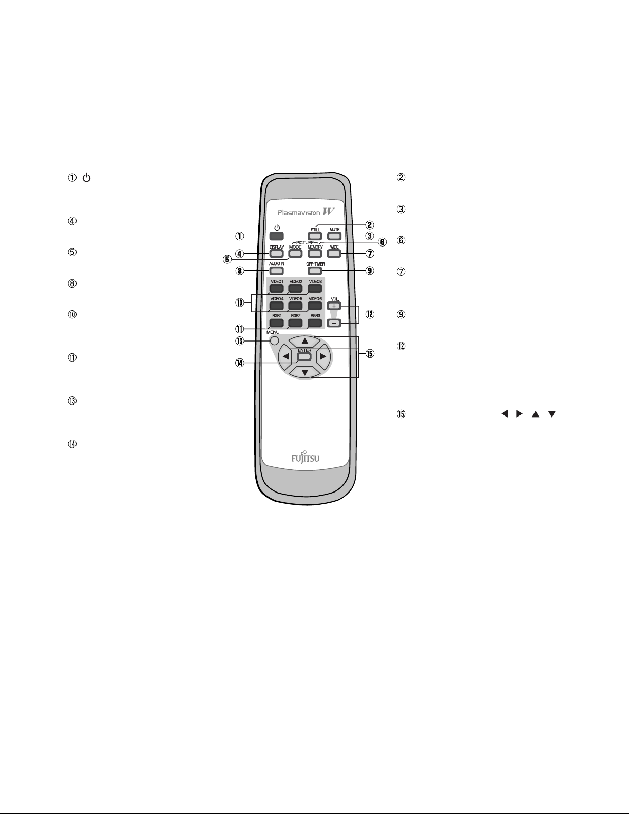
REMOTE CONTROL
button
Switches between power ON and standby
state.
DISPLAY OFF button
For showing on-screen-information.
PICTURE MODE button
Switches the picture mode.
AUDIO IN button
Selects the input audio.
Video input mode selector button
[VIDEO 1 - 6]
Selects VIDEO 1 - 6
RGB input mode selector button
[RGB 1 - 3]
Selects RGB 1 - 3.
Menu button [MENU]
Use this button to display a desired menu
for adjusting the picture.
Enter button [ENTER]
Press this button to finalize the selection of
a desired menu or option within a menu.
STILL button
Displays a still picture during viewing.
MUTE button
Temporarily mutes the sound.
PICTURE MEMORY button
Recalls the PICTURE MEMORY.
WIDE button
Switches the screen over to a desired wide
screen.
OFF-TIMER
Sets when the power should be turned of f.
Volume adjustment buttons
[VOL +/- ]
Adjust the volume.
Press the + button to increase the volume.
Press the - button to reduce the volume.
Adjustment buttons [
Use these buttons to scroll through options
in a menu.
/ / / ]
- 41 -
Page 43

Model : P42HHA10W/E
REMOTE CONTROL
button
Switches between power ON and standby
state.
DISPLAY OFF button
For showing on-screen-information.
PICTURE MODE button
Switches the picture mode.
RGB input mode selector button
[RGB 1 - 2]
Selects RGB 1 - 2.
Video input mode selector button
[VIDEO 1 - 3]
Selects VIDEO 1 - 3.
Menu button [MENU]
Use this button to display a desired menu
for adjusting the picture.
Enter button [ENTER]
Press this button to finalize the selection of
a desired menu or option within a menu.
MUTE button
Temporarily mutes the sound.
PICTURE MEMORY button
Recalls the PICTURE MEMORY.
WIDE button
Switches the screen over to a desired wide
screen.
RGB3/VIDEO4 input mode selector
button [RGB3/VIDEO4]
Selects RGB3 or VIDEO4.
Volume adjustment buttons
[VOL +/ - ]
Adjust the volume.
Press the + button to increase the volume.
Press the - button to reduce the volume.
Adjustment buttons [
Use these buttons to scroll through options
in a menu.
/ / / ]
- 42 -
Page 44

VIDEO MODE ADJUSTMENT
Model : P42HHS10W/E
REMOTE CONTROLLER
VIDEO 1
VIDEO 2
VIDEO 3
VIDEO 4
VIDEO 5
VIDEO 6
RGB 1
RGB 2
RGB 3
VOL. +
VOL. -
STILL
MUTE
DISPLAY
PICTURE MODE
PICTURE MEMORY
AUDIO IN
OFF-TIMER
WIDE
Normal
Wide 1
Wide 2
Zoom 1
Zoom 2
Dynamic
Fine
Real 1
Real 2
Static
Load
Save
Analog Audio
Digital Audio 1
Digital Audio 2
Off
30min.
60min.
90min.
120min.
Normal
Auto
Wide 1
Wide 2
Zoom 1
Zoom 2
Memory 1
Memory 2
Memory 3
Memory 4
Memory 5
Memory 6
Memory 7
Memory 8
MENU
ENTER
PICTURE
POSITION/SIZE
AUDIO
FEATURES
FACTORY DEFAULT
Contrast
Brightness
Color
Tint
Sharpness
Picture Mode
Precision Setting
Noise Reduction
Picture Memory
Default
Position
Size
Default
Treble
Bass
Balance
Loudness
Adjustment*
Function
On Screen Menu
Input Terminal
Others
Execute
{-30 to +30}
{-60 to +60}
{-60 to +60}
{-30 to +30}
{-16 to +16}
Dynamic
Fine
Real 1
Real 2
Static
Luminance
Black Level
Colour Temp.
User Color Temp.
Off
Min.
Std.
Max.
Load
Save
Yes
No
Horizontal
Vertical
Width
Height
Yes
No
{-6 to +6}
{-6 to +6}
{-10 to +10}
Off
Min.
Mid.
Max.
Clamp Position* *Only Comp. Video{-8 to +8}
24 Frame Mode
Jaggies Filter
OSD
Language
Name Select
Video Input 1
Video Input 2
Video Input 3
Video Input 4
DVI Input
Power saver
White Screen
Exhibition Mode
Illumination
Information
Yes
No
{40 to 100%}
Can be set when Fine is
}
selected as the Picture Mode.
{-15 to +15}
{-3500 to +3500}
Red
Green
Blue
Memory 1
Memory 2
Memory 3
Memory 4
Memory 5
Memory 6
Memory 7
Memory 8
{-30 to +30 (Comp. video -16 to +16)}
{-7 to +7 (Zoom -15 to +15) (Comp. video -16 to +16)}
{-3 to +12 (Comp. video -2 to +16)}
{-3 to +12 (Comp. video -2 to +16)}
On
Off
On
Off
On(OSD : bright)
On(OSD : dark)
Off
English
Deutsch
~
Espanol
Francais
~
Italiano
Portugues
Video
RGB RGB 1
Video input
Video Format
DVI 1
DVI 2
Auto Off - UNTOUCH
Auto Off - NO SIG.
On
Off
On
Off
On
Off
Mode
Freq. Scan Mode
Input Signal
Freq.
{0 to 255}
{0 to 255}
{0 to 255}
<
Video 1
Video 2
Video 3
Video 4
Video 5
Video 6
RGB 2
RGB 3
Auto
Video
S-video
Comp. video
Auto 1
Auto 2
NTSC
PAL
SECAM
PAL60
N-PAL
M-PAL
4.43NTSC
Off
On
Off
On
Video 1
DVD 1
DVD 2
VCR 1
VCR 2
GAME
Camcorder
STB
Satellite
Cable TV
Video 1
PC 1
PC 2
DVD 1
DVD 2
STB
Satellite
Cable TV
Position Horizontal "-"
Horizontal "+"
Vertical "-"
Vertical "+"
Size Width "-"
Width "+"
Height "-"
Height "+"
- 43 -
Page 45

VIDEO MODE ADJUSTMENT
Model : P42HHA10W/E
REMOTE CONTROLLER
VIDEO 1
VIDEO 2
VIDEO 3
RGB 1
RGB 2
RGB 3 / VIDEO 4
VOL. +
VOL. -
MUTE
DISPLAY
PICTURE MODE
PICTURE MEMORY
WIDE
Normal
Wide 1
Wide 2
Zoom 1
Zoom 2
Dynamic
Fine
Real 1
Real 2
Static
Load
Save
Normal
Auto
Wide 1
Wide 2
Zoom 1
Zoom 2
Memory 1
Memory 2
Memory 3
Memory 4
Memory 5
Memory 6
Memory 7
Memory 8
MENU
ENTER
PICTURE
POSITION/SIZE
AUDIO
FEATURES
FACTORY DEFAULT
Contrast
Brightness
Color
Tint
Sharpness
Picture Mode
Precision Setting
Noise Reduction
Picture Memory
Default
Position
Size
Default
Treble
Bass
Balance
Loudness
Adjustment*
Function
On Screen Menu
Input Terminal
Others
Execute
{-30 to +30}
{-60 to +60}
{-60 to +60}
{-30 to +30 (Comp. video -60 to +60)}
{-16 to +16}
Dynamic
Fine
Real 1
Real 2
Static
Luminance
Black Level
Colour Temp.
User Color Temp.
Off
Min.
Std.
Max.
Load
Save
Yes
No
Horizontal
Vertical
Width
Height
Yes
No
{-6 to +6}
{-6 to +6}
{-10 to +10}
On
Off
Clamp Position* *Only Comp. Video{-8 to +8}
24 Frame Mode
OSD
Language
Name Select
Video Input
S-video Input
D-SUB Input
DVI Input
Audio Input
White Screen
Exhibition Mode
Information
Yes
No
{40 to 100%}
{-15 to +15}
{-3500 to +3500}
Red
Green
Blue
Memory 1
Memory 2
Memory 3
Memory 4
Memory 5
Memory 6
Memory 7
Memory 8
{-30 to +30 (Comp. video -16 to +16)}
{-7 to +7 (Zoom -15 to +15) (Comp. video -16 to +16)}
{-3 to +12 (Comp. video -2 to +16)}
{-3 to +12 (Comp. video -2 to +16)}
On
Off
On(OSD : bright)
On(OSD : dark)
Off
English
Deutsch
Espanol
Francais
Italiano
Portugues
RGB 1
RGB 2
Video 1
Video 2
Video 3
Video 4
Auto 1
Auto 2
NTSC
PAL
SECAM
PAL60
N-PAL
M-PAL
4.43NTSC
RGB-PC
Decoder
DVI 1
DVI 2
RGB 1
RGB 2
Video 1
Video 2
Video 3
Video 4
On
Off
On
Off
Mode
Freq. Scan Mode
Input Signal
Freq.
Can be set when Fine is
}
selected as the Picture Mode.
{0 to 255}
{0 to 255}
{0 to 255}
~
~
<
RGB 1
PC 1
PC 2
DVD 1
DVD 2
STB
Satellite
Cable TV
Video 1
DVD 1
DVD 2
VCR 1
VCR 2
GAME
Camcorder
STB
Satellite
Cable TV
Mask
No Audio
Audio 1
Audio 2
Audio 3
Position Horizontal "-"
Horizontal "+"
Vertical "-"
Vertical "+"
Size Width "-"
Width "+"
Height "-"
Height "+"
Mask Off
Mask 5
Off
5
10
15
Mask 10
Mask 15
- 44 -
Page 46

RGB MODE ADJUSTMENT
Model : P42HHS10W/E
REMOTE CONTROLLER
VIDEO 1
VIDEO 2
VIDEO 3
VIDEO 4
VIDEO 5
VIDEO 6
RGB 1
RGB 2
RGB 3
VOL. +
VOL. -
STILL
MUTE
DISPLAY
PICTURE MODE
PICTURE MEMORY
AUDIO IN
OFF-TIMER
WIDE
Normal
Wide
Zoom
Position Horizontal "-"
Horizontal "+"
Vertical "-"
Vertical "+"
Dynamic
Fine
Real 1
Real 2
Static
Load
Save
Analog Audio
Digital Audio 1
Digital Audio 2
Off
30min.
60min.
90min.
120min.
Normal
Wide
Zoom
Memory 1
Memory 2
Memory 3
Memory 4
Memory 5
Memory 6
Memory 7
Memory 8
MENU
ENTER
PICTURE
POSITION/SIZE
AUDIO
FEATURES
FACTORY DEFAULT
Contrast
Brightness
Color
Tint
Sharpness
Picture Mode
Precision Setting
Picture Memory
Default
Position
Size
Default
Treble
Bass
Balance
Loudness
Adjustment
On Screen Menu
Input Terminal
Others
Execute
{-30 to +30}
{-60 to +60}
{-60 to +60}
{-60 to +60}
{-4 to +4}
Dynamic
Fine
Real 1
Real 2
Static
Luminance
Black Level
Color Temp.
User Colour Temp.
Load
Save
Yes
No
Horizontal
Vertical
Width
Height
Yes
No
{-6 to +6}
{-6 to +6}
{-10 to +10}
Off
Min.
Mid.
Max.
Dot Clock
Clock Phase
Clamp Position
Auto Calibration
OSD
Language
Name Select
Video Input 1
Video Input 2
Video Input 3
Video Input 4
DVI Input
Power saver
Screen Orbiter
Direct Setting
Code Setting
Yes
No
{40 to 100%}
Can be set when Fine is
}
selected as the Picture Mode.
{-15 to +15}
{-3500 to +3500}
Red
Green
Blue
Memory 1
Memory 2
Memory 3
Memory 4
Memory 5
Memory 6
Memory 7
Memory 8
{-150 to +150}
{-150 to +150}
{-12 to +25}
{-12 to +25}
{-60 to +60}
Auto
Manual {1 to 32}
{-8 to +8}
Execute
On(OSD : bright)
On(OSD : dark)
Off
English
Deutsch
~
Espanol
Francais
~
Italiano
Portugues
Video
RGB RGB 1
Video input
Video Format
DVI 1
DVI 2
Auto Off - UNTOUCH
Auto Off - NO SIG.
DPMS
Mode / Time
Moving Area
Auto
VGA
WVGA
480P
XGA
WXGA
Auto
Manual {00 to 1F} *Hexadecimal
{0 to 255}
{0 to 255}
{0 to 255}
Yes
No
<
Video 1
Video 2
Video 3
Video 4
Video 5
Video 6
RGB 2
RGB 3
Auto
Video
S-video
Comp. video
Auto 1
Auto 2
NTSC
PAL
SECAM
PAL60
N-PAL
M-PAL
4.43NTSC
Off
On
Off
On
Time
Background
Off
Time
Mode
Min.
Std.
Max.
Video 1
DVD 1
DVD 2
VCR 1
VCR 2
GAME
Camcorder
STB
Satellite
Cable TV
Video 1
PC 1
PC 2
DVD 1
DVD 2
STB
Satellite
Cable TV
Off
1 min.
15 min.
45 min.
60 min.
Black
White
White Screen
Exhibition Mode
Illumination
Information
Size Width "-"
Height "-"
Height "+"
Moving Area Std. (10 dot)
Moving Area Max. (15 dot)
Moving Area Min. (5 dot)
On
Off
On
Off
On
Off
Mode
Freq. Scan Mode
Input Sync
Freq.
Preset No.
Width "+"
- 45 -
Page 47

RGB MODE ADJUSTMENT
Model : P42HHA10W/E
REMOTE CONTROLLER
VIDEO 1
VIDEO 2
VIDEO 3
RGB 1
RGB 2
RGB 3 / VIDEO 4
VOL. +
VOL. -
MUTE
DISPLAY
PICTURE MODE
PICTURE MEMORY
WIDE
Normal
Wide
Zoom
Position Horizontal "-"
Horizontal "+"
Vertical "-"
Vertical "+"
Dynamic
Fine
Real 1
Real 2
Static
Load
Save
Normal
Wide
Zoom
Memory 1
Memory 2
Memory 3
Memory 4
Memory 5
Memory 6
Memory 7
Memory 8
MENU
ENTER
PICTURE
POSITION/SIZE
AUDIO
FEATURES
FACTORY DEFAULT
Contrast
Brightness
Color
Tint
Sharpness
Picture Mode
Precision Setting
Picture Memory
Default
Position
Size
Default
Treble
Bass
Balance
Loudness
Adjustment
On Screen Menu
Input Terminal
Others
Execute
{-30 to +30}
{-60 to +60}
{-60 to +60}
{-60 to +60}
{-4 to +4}
Dynamic
Fine
Real 1
Real 2
Static
Luminance
Black Level
Color Temp.
User Color Temp.
Load
Save
Yes
No
Horizontal
Vertical
Width
Height
Yes
No
{-6 to +6}
{-6 to +6}
{-10 to +10}
On
Off
Dot Clock
Clock Phase
Clamp Position
Auto Calibration
OSD
Language
Name Select
Video Input
S-video Input
D-SUB Input
DVI Input
DPMS
Audio Input
Screen Orbiter
Yes
No
{40 to 100%}
Can be set when Fine is
}
selected as the Picture Mode.
{-15 to +15}
{-3500 to +3500}
Red
Green
Blue
Memory 1
Memory 2
Memory 3
Memory 4
Memory 5
Memory 6
Memory 7
Memory 8
{-150 to +150}
{-150 to +150}
{-12 to +25}
{-12 to +25}
{-60 to +60}
Auto
Manual {1 to 32}
{-8 to +8}
Execute
On(OSD : bright)
On(OSD : dark)
Off
English
Deutsch
~
Espanol
Francais
~
Italiano
<
Portugues
RGB 1
RGB 2
Video 1
Video 2
Video 3
Video 4
Auto 1
Auto 2
NTSC
PAL
SECAM
PAL60
N-PAL
M-PAL
4.43NTSC
RGB-PC
Decoder
DVI 1
DVI 2
Time
Background
RGB 1
RGB 2
Video 1
Video 2
Video 3
Video 4
Mode / Time
Moving Area
{0 to 255}
{0 to 255}
{0 to 255}
RGB 1
PC 1
PC 2
DVD 1
DVD 2
STB
Satellite
Cable TV
Video 1
DVD 1
DVD 2
VCR 1
VCR 2
GAME
Camcorder
STB
Satellite
Cable TV
Yes
No
Mask
Off
1 min.
15 min.
45 min.
60 min.
Black
White
No Audio
Audio 1
Audio 2
Audio 3
Off
Time
Mode
Min.
Std.
Max.
Size Width "-"
Width "+"
Height "-"
Height "+"
Moving Area Std. (10 dot)
Moving Area Max. (15 dot)
Moving Area Min. (5 dot)
Mask Off
Mask 5
Mask 10
Off
5
10
15
Direct Setting
Code Setting
White Screen
Exhibition Mode
Information
Mask 15
Auto
VGA
WVGA
480P
XGA
WXGA
SXGA
+
SXGA
Auto
Manual {00 to 27} *Hexadecimal
On
Off
On
Off
Mode
Freq. Scan Mode
Input Sync
Freq.
Preset No.
- 46 -
Page 48

TROUBLESHOOTING USING LED AND OSD
1. Display
(1) OSD
Three kinds of error messages are displayed on the screen, and the power is turned off 10 sec later.
(2) LED
LED error is displayed continuously after the power is turned off.
2. Error types and check points
(1) OSD
On screen display Cause Check point
ERROR MESSAGE CONDITION 1
ERROR MESSAGE CONDITION 2
ERROR MESSAGE CONDITION 3
Fan protector operated
Temperature protector
operated
EEPROM error
Fan (Display unit)
Main power PCB (Display unit)
Main PCB (Display unit)
Ambient temperature of unit
Main PCB (Display unit)
Temp. sensor IC757 (Display
unit)
Main PCB (Display unit)
Main(Digital/Video) PCB
(Selector unit)
(2) LED
Display
LED lamp display status Cause Check point
Steady light (Red)
Continuous
Flashes continuously (Red)
1 time
Flashes once every 4 sec. (Red)
2 times
Flashes twice every 5 sec. (Red)
3 times
Flashes three times every 6 sec. (Red)
5 times
Flashes five times every 8 sec. (Red)
Selector unit
Stand-by status
No power
Power supply protector
operated
Fan protector operated Fan
Temperature protector
operated
PDP panel AC error
EEPROM error Main PCB
Audio circuit faulty Audio PCB Assy
Main power PCB
PDP panel
Main power PCB
Main PCB
Ambient temperature of unit
Temperature sensor IC757
Main PCB
Panel AC
LED lamp display status Cause Check point
Steady light (Red)
Continuous
Flashes continuously (Red)
Stand-by status
No power
Power supply protector
operated
Main power PCB
3 times
Flashes three times every 6 sec. (Red)
4 times
Flashes four times every 7 sec. (Red)
5 times
Flashes five times every 8 sec. (Red)
EEPROM error
Main(Digital) circuit faulty
Audio circuit faulty Audio PCB Assy
- 47 -
Main(Digital/Video) PCB
Main(Digital) PCB
Page 49

Model : P42HHA10W/E
1. Display
(1) OSD
Three kinds of error messages are displayed on the screen, and the power is turned off 10 sec later.
(2) LED
LED error is displayed continuously after the power is turned off.
2. Error types and check points
(1) OSD
On screen display Cause Check point
ERROR MESSAGE CONDITION 1
ERROR MESSAGE CONDITION 2 Temperature protector
(2) LED
Fan protector operated
operated
LED lamp display status Cause Check point
Steady light (Red)
Continuous
Flashes continuously (Red)
1 time
Flashes once every 4 sec. (Red)
2 times
Flashes twice every 5 sec. (Red)
Stand-by status
No power
Power supply protector
operated
Fan protector operated Fan
Temperature protector
operated
Fan
Main power PCB
Main/Digital PCB
Ambient temperature of unit
Main/Digital PCB
Temp. sensor IC757
Main power PCB
PDP panel
Main power PCB
Main/Digital PCB
Ambient temperature of unit
Temperature sensor IC757
Main/Digital PCB
4 times
Flashes four times every 7 sec. (Red)
5 times
Flashes five times every 8 sec. (Red)
Main/Digital circuit faulty Main/Digital PCB
Video circuit faulty Video PCB Assy
- 48 -
Page 50

TROUBLESHOOTING FLOWCHART
Model : P42HHS10W/E
LED lamp blinking
Display unit
Turn power on and check
state of lamp.
LAMP STATE
Not lighted.
RED
RED
RED
RED
Blinks
Blinks continuously.
continuously.
Blinks once
Blinks twice
Note : 1. Since a voltage is applied to the Main Power
POWER SUPPLY STATE
Power supply
circuit faulty.
Power turned off
Power turned off
immediately.
immediately.
Power turned off
after 10 sec.
Power turned off
after 10 sec.
PCB heat sinks while the set is operating, do
not touch the heat sinks.
REMEDY
∗ Replace Main
Power PCB.
∗ Vs and V
Check 1
Check 1
Check 2
Check 3
a must be adjusted.
RED
RED
GREEN
Blinks three times
Blinks five times
Lights steadily for
more than 10 sec.
Replace selector unit
and operates OK?
YES
Check selector unit
Power not turned
off, LED blinks only.
Power not turned
off, LED blinks only.
NO
Replace Main
PCB Assy.
Replace Audio PCB
Assy.
Replace Main(Digital)
PCB Assy.
- 49 -
Page 51

Model : P-SU4H10W/E
LED lamp blinking
Selector unit
Turn power on and check
state of lamp.
LAMP STATE
Not lighted.
RED
RED
RED
RED
Blinks
Blinks continuously.
continuously.
Blinks three times
Blinks four times
Note : 1. Since a voltage is applied to the Main Power
POWER SUPPLY STATE
Power supply
circuit faulty.
Power turned off
Power turned off
immediately.
immediately.
Power not turned
off, LED blinks only.
Power not turned
off, LED blinks only.
PCB heat sinks while the set is operating, do
not touch the heat sinks.
REMEDY
∗ Replace Main
Power PCB.
∗ Vs and V
Check 1
Check 4
Replace Main(Digital)
PCB Assy.
Replace Main(Digital)
PCB Assy.
a must be adjusted.
RED
GREEN
Blinks five times
Lights steadily for
more than 10 sec.
Replace display unit
and operates OK?
Is on-screen display
normal?
YES
Power not turned
off, LED blinks only.
YES
NO
All input image
faulty.
Video input image
faulty.
S-video input image
faulty.
Component video
input image faulty.
Check display unit
Check 5
Signal processing
PCB faulty.
Check 6
Check 6
Check 7
Replace Main(Video)
PCB Assy.
Replace Main(Digital)
PCB Assy.
RGB input image
faulty.
Check 8
- 50 -
Page 52

Model : P42HHS10W/E
Check 1
Power supply protector operated
Power lamp : Flashing continuously in red.
Start
(1) Pull out Power Cord Plug and disconnect connectors CN6, CN23, CN33, CN42 and CN52
on Main Power PCB.
(2) Connect pin 1 and pin 13 of CN352 through a 1/4W, 1KΩ resistor.
Connect pin 1 of CN352 and pin 5 of CN309 through a 1/4W, 1KΩ resistor.
CN502 shorted.
(3)
Plug in Power Cord Plug and turn on power switch.
Does
lamp change to
green?
No
(1) Pull out Power Cord Plug and disconnect connectors CN351 and CN352 on Main Power
PCB.
(2) Connect pin 1 and pin 13 of CN352 through a 1/4W, 1KΩ resistor.
Connect pin 1 of CN352 and pin 5 of CN309 through a 1/4W, 1KΩ resistor.
CN502 shorted.
(3)
Disconnect connectors on Main Power PCB. (CN6, CN23, CN33, CN42, CN52)
(4)
Plug in Power Cord Plug and turn on power switch.
Yes
PDP faulty.
(at an interval of 1 sec.)
Replace PDP.
∗
∗ Vs and
Va
must be adjusted.
Is voltage
at each connector on
Main Power PCB normal?
See page **
Yes
(1) Pull out Power Cord Plug and connect connectors CN351 and CN352 to Main Power PCB.
Plug in Power Cord Plug and turn on power switch.(2)
(3) Check state of green lamp.
Does
lamp change to
green?
Yes
No
No
Power Supply
circuit faulty.
Main circuit faulty.
Main circuit faulty.
Replace Main
∗
Power PCB.
∗ Vs and
Va
must be adjusted.
Replace Main PCB
Assy.
Replace Main PCB
Assy.
- 51 -
Page 53

Adjust PDP unit installation so that
peripheral temperature is 40.0 or
less.
(For 0.5 sec. at an interval of 5 sec.)
Replace
Main PCB
Assy.
Microcomputer
peripheral circuit
faulty.
Replace
temperature sensor
IC757.
Temperature protector operated
No
Power lamp : Flashes intermittently twice in red.
Start
Is ambient temperature
Check 3
Yes
less than 60 ?
of IC757 on Main PCB
Power Supply Unit
No
Does unit
operate normally
when temperature sensor
circuit faulty.
∗Replace Main
Temperature
IC757 changed ?
Power PCB.
Yes
Replace
adjusted.
∗Vs and Va must be
sensor IC757 faulty.
Main PCB
Assy.
Replace
Main PCB
Assy.
(For 0.5 sec. at an interval of 4 sec.)
Fan protector operated
Power lamp: Flashes once intermittently in red.
Start
No
Is voltage
at connectors
Check 2
Main PCB 14V?
CN352 and on
Yes
- 52 -
Microcomputer
peripheral circuit
faulty.
No
Yes
Is voltage at connectors CN953,
CN954 on Main PCB normal?
+ and - of CN953, 954
5V to 11V.
Fan faulty Replace fan.
No
Is fan rotary signal of
Main PCB normal ?
Pin of CN953, CN954
Microcomputer
16 to 90 Hz.
peripheral circuit
faulty.
Yes
Page 54

Check 4
Power supply protector operated
Power lamp : Flashing continuously in red.
Start
(1) Pull out Power Cord Plug and disconnect connectors CN202, CN203, CN204 on Main
Power PCB.
(2) Plug in Power Cord Plug and turn on power switch.
Is voltage
at each connector on
Main Power PCB normal?
See page **
Yes
(1) Pull out Power Cord Plug and connect connectors CN202, CN203, CN204 to Main Power
PCB.
(2) Pull out Power Cord Plug and disconnect connectors CN4101, CN4155 on Audio-selector
PCB
(3)
Plug in Power Cord Plug and turn on power switch.
(4)
Check state of green lamp.
No
Power Supply
circuit faulty.
(at an interval of 1 sec.)
∗
Replace Main
Power PCB.
∗ Vs and V
a must be adjusted.
Does
lamp change to
green?
Yes
No
Main circuit faulty.
Audio-selector
circuit faulty.
Replace Main PCB
Assy.
Replace Audioselector PCB Assy.
- 53 -
Page 55

Check 5
OSD is not displayed
Power lamp : Lighted green.
(10 sec or more)
Start
Is picture
displayed on-screen
when signal input?
No
Is voltage at
each connector on
Power PCB Normal?
Yes
Yes
Signal processing
circuit faulty
Signal processing
circuit faulty
No
Power Supply
circuit faulty
Replace Main PCB
Assy
Replace Power
PCB Assy
Replace Main
PCB Assy
- 54 -
Page 56

Check 6
Start
Video/S-video input signal are abnormal.
Power lamp : Lighted green
(10 sec or more)
Does mode
selection operate?
(VIDEO1-6/RGB1-3)
Yes
(1) Make sure connectors CN3402-CN1101 are properly inserted.
Make sure PCBs M02CZ and M02GL(M02GM) are correctly connected.(2)
(3)
Is signal at connector CN3402 -Video, -Y/ -pin C(CN1101 -Video, -Y/ -C) correct?
Is signal
of connector
CN3402(CN1101)
correct?
Yes
No
No
Microcomputer
peripheral circuit
faulty
Selector circuit
faulty
Video circuit
faulty
Replace Main
PCB Assy
Replace Terminal
PCB
Replace Main(Video)
PCB Assy
- 55 -
Page 57

Check 7
Start
Component input signal are abnormal.
Power lamp : Lighted green
(10 sec or more)
Does mode selection
operate?(VIDEO1-6/RGB1-3)
Yes
(1) Make sure PCBs M02CZ and M02GL(M02GM) are correctly connected.
Only
VIDEO 1/2/4
abnormal?
No
Only
VIDEO 5/6(RGB2/3)
abnormal?
No
Is 525i/625i
signal correctly
displayed?
Yes
Yes
Yes
No
Microcomputer
peripheral circuit
faulty
Selector circuit
faulty
Selector circuit
faulty
Signal processing
circuit faulty
Replace Terminal
PCB
Replace Video
selector PCB
Replace Main(Video)
PCB Assy
Replace
Main(Digital) PCB
Assy
No
Is signal
input level
normally?
No
Check input signal
Yes
∗SYNC signals are added to the Y signal.
Signal processing
circuit faulty
- 56 -
Replace Main(Video)
PCB Assy
Page 58

Model : P42HHA10W/E
LED lamp blinking
Turn power on and check
state of lamp.
LAMP STATE
Not lighted.
RED
RED
RED
RED
Blinks
Blinks continuously.
continuously.
Blinks once
Blinks twice
Note : 1. Since a voltage is applied to the Main Power
POWER SUPPLY STATE
Power supply
circuit faulty.
Power turned off
Power turned off
immediately.
immediately.
Power turned off
after 10 sec.
Power turned off
after 10 sec.
PCB heat sinks while the set is operating, do
not touch the heat sinks.
2. If the Main Power PCB insulation sheet is not
installed when assembling, the Main Power
PCB fuse will blow.
REMEDY
∗ Replace Main
Power PCB.
∗ Vs and V
Check 1
Check 1
Check 2
Check 3
a must be adjusted.
RED
RED
GREEN
Blinks four times
Blinks five times
Lights steadily for
more than 10 sec.
Is on-screen display
normal?
YES
Power not turned
off, LED blinks only.
Power not turned
off, LED blinks only.
NO
All input image
faulty.
Video input image
faulty.
S-video input image
faulty.
Component video
input image faulty.
Check 4
Signal processing
PCB faulty.
Check 5
Check 5
Check 6
Replace Main/Digital
PCB Assy.
Replace Video PCB
Assy.
Replace Main/Digital
PCB Assy.
RGB input image
faulty.
Check 7
- 57 -
Page 59

Check 1
Power supply protector operated
Power lamp : Flashing continuously in red.
Start
(1) Pull out Power Cord Plug and disconnect connectors CN6, CN23, CN33, CN42 and CN52
on Main Power PCB.
(2) Connect pin 1 and pin 13 of CN352 through a 1/4W, 1KΩ resistor.
Connect pin 1 of CN352 and pin 5 of CN509 through a 1/4W, 1KΩ resistor.
CN502 shorted.
(3)
Plug in Power Cord Plug and turn on power switch.
(at an interval of 1 sec.)
Does
lamp change to
green?
No
(1) Pull out Power Cord Plug and disconnect connectors CN351 and CN352 on Main Power
PCB.
(2) Connect pin 1 and pin 13 of CN352 through a 1/4W, 1KΩ resistor.
Connect pin 1 of CN352 and pin 5 of CN509 through a 1/4W, 1KΩ resistor.
CN502 shorted.
(3)
Disconnect connectors on Main Power PCB. (CN6, CN23, CN33, CN42, CN52)
(4)
Plug in Power Cord Plug and turn on power switch.
Is voltage
at each connector on
Main Power PCB normal?
See page **
Yes
(1) Pull out Power Cord Plug and connect connector CN351 and CN352 to Power Supply Unit.
(2) Remove Video PCB Assy.
Plug in Power Cord Plug and turn on power switch.(3)
(4) Check state of green lamp.
Yes
No
PDP faulty.
Power Supply
circuit faulty.
Replace PDP.
∗
∗ Vs and
Replace Main
∗
Power PCB.
∗ Vs and
Va
Va
must be adjusted.
must be adjusted.
Is green
lamp lit
continuously?
Yes
No
Main/Digital
circuit faulty.
Video circuit
faulty.
- 58 -
Replace Main
/Digital PCB Assy.
Replace Video PCB
Assy.
Page 60

Adjust PDP unit installation so that
peripheral temperature is 40.0 or
less.
(For 0.5 sec. at an interval of 5 sec.)
Replace
Main/Digital
PCB Assy.
Microcomputer
peripheral circuit
faulty.
Replace
temperature sensor
IC757.
Temperature protector operated
No
Power lamp : Flashes intermittently twice in red.
Start
Is ambient temperature
Check 3
Yes
PCB less than 60 ?
of IC757 on Main/Digital
Power Supply Unit
circuit faulty.
No
Does unit
operate normally
IC757 changed ?
when temperature sensor
Power PCB.
∗Replace Main
adjusted.
∗Vs and Va must be
Temperature
sensor IC757 faulty.
Yes
Replace
Main/Digital
PCB Assy.
Replace
Main/Digital
PCB Assy.
(For 0.5 sec. at an interval of 4 sec.)
Fan protector operated
Power lamp: Flashes once intermittently in red.
Start
No
Is voltage
at connectors
Check 2
Main PCB 14V?
CN352 and on
Yes
- 59 -
Microcomputer
peripheral circuit
faulty.
No
Yes
Is voltage at connectors CN951,
CN952 on Main/Digital PCB
+ and - of CN951 and 952
5V to 11V.
normal?
Microcomputer
Fan faulty Replace fan.
No
Is fan rotary signal of
Main/Digital PCB normal ?
Pin of CN951, CN952
16 to 90 Hz.
peripheral circuit
Yes
faulty.
Page 61

Check 4
OSD is not displayed
Power lamp : Lighted green.
(10 sec or more)
Start
Is picture
displayed on-screen
when signal input?
No
Is voltage at
each connector on
Main Power PCB
Normal?
Yes
Is picture displayed
normally when PDP
changed?
No
Yes
Signal processing
circuit faulty.
Signal processing
circuit faulty.
No
Power Supply
circuit faulty.
Yes
PDP panel faulty.
Replace Main/Digital
PCB Assy.
Replace Main
Power PCB.
Replace PDP
panel.
Replace Main/Digital
PCB Assy.
- 60 -
Page 62

Check 5
Start
Video 1/ Video 2/ Video 3 input signal are abnormal.
Power lamp : Lighted green
(10 sec or more)
Can this unit
select only RGB mode?
No
Is picture
displayed on screen
normal when new video
PCB unit installed ?
No
Is signal input level
normal?
No
Yes
Yes
Yes
Microcomputer
peripheral circuit
faulty
Video PCB Assy
faulty.
Signal processing
circuit faulty.
Replace Video
PCB Assy.
Replace Main/Digital
PCB Assy.
Check input signal.
- 61 -
Page 63

Check 6
Start
Video 4 are abnormal.
Power lamp : Lighted green
(10 sec or more)
Can this unit select
only RGB mode ?
No
Is picture
displayed on screen
normal when new
Video PCB Unit
installed ?
No
Are brightness
and color difference
signals connected to
input terminals
correctly ?
Yes
Is signal
input level
normally?
Yes
Yes
Yes
No
Install Video PCB
Unit faulty.
Video PCB Unit
faulty.
Check connection
cable.
Signal processing
circuit faulty.
Replace Video PCB
Assy.
Replace Main/Digital
PCB Assy.
No
Check input signal
∗SYNC signals are added to the Y signal.
- 62 -
Page 64

No
No
Ye s
cable ?
Is composite sync.
signal input to pin 13 of RGB
Make sync. signal polarity output
from signal source negative, or make
output impedance TTL.
Check connection cable.
No
Check input signal.
Start
RGB input is abnormal.
Power lamp: Lighted green
k
Chec 7
Ye s
Is RGB
appropriate ?
cable pin arrangement
(10 sec or more)
Sync. on green signal
source ?
What kind of
Is composite sync.
signal is output from signal
Check input signal.
Separate signal Composite signal
No
.
le ?
io
io
io
Is horizontal sync.
RGB cable ?
signal input to pin 14 of
signal input to pin 13 and vertical sync
Ye s
le ?
cable ?
signal input to pin 2 of RGB
No
Ye s
negative ?
Is Sync. signal
TLL and polarity
Connect RGB cable
to terminal.
Yes
Check input signal.NoCheck input signal.
No
Ye s
∗
Is input level(∗) within specified
Is frequency of horizontal sync.
and vertical sync signals within
specified range ?
range ?
Note(∗): If the synchronizing signal cannot be identified by
TTL level, it in the 75Ω terminated state.
.
.
.
Ye s
Signal processing circuit faulty.
.
Replace Main/Digital PCB Assy.
- 63 -
Page 65

VOLTAGE OF EACH CONNECTOR
1. How to measure the voltages on the Main Power Supply PCB in protect mode.
Since a voltage is applied to the Main Power PCB heat sinks while the set is operating,
do not touch the heat sinks.
After the power cord plug was pulled out, do not pull out the connector on the Main Power PCB until
the Green LED (D531: Discharge check LED) turns off.
1) Disconnect CN6, CN23, CN33, CN42 and CN52
2)
Connect pin 1 and pin 13 of CN352 through a 1/4W, 1k resistor.
Connect pin 1 of CN352 and pin 5 of CN509 through a 1/4W, 1k resistor.
CN502 shorted.
3) Press the power button.
2. On the Main Power Supply PCB. (M02FQ)
CN352
No. NAME SPEC.
1 P5V 5.0V +/- 0.25V 5
3 +14V 14.0V +/- 0.7V 5
6 -8V -8.0V +/- 0.4V 7
CN33
No. NAME SPEC.
1 Vcc 1 5.1V +/- 0.25V 2
9 Vs 82.5V +/- 1.5V 5
CN6
No. NAME SPEC.
1 Vpri2 3.3V +/- 0.15V 3
Ground
Ground
Ground
CN351
No. NAME SPEC.
3 +2.5V 2.5V +/- 0.13V 2
7 +3.3V 3.3V +/- 0.17V 6
12 +6.5V 6.5V +/- 0.33V
CN23
No. NAME SPEC.
1 Va 60.0V +/- 1.3V 4
Ground
11
Ground
- 64 -
Page 66

VS AND VA ADJUSTMENT
When the Main Power Supply PCB and PDP panel are replaced, Vs and VAmust be
adjusted.
Preparation : Heat-run for 5 minutes with a white pattern in the wide mode.
Adjustment : Adjust the V
Check points : Refer to the drawing shown below.
Adjustment points : Refer to the drawing shown below.
Adjustment value : Within +/- 0.1V of voltage indicated on the label of the PDP panel.
S
and VAin the no-signal state.
- MAIN POWER SUPPLY PCB (M02FQ-PCB) -
T2
T3
CN3
T4
CN1
CN2
CN352
CN507
CN351
CN502
VA
VR581
CN901
CN7
ADJ.
ADJ
VS
VR582
CN509
CN33
CN6 CN42
CN508
CN23
CN52
VS & VA
check point
CN508
1 pin GND
2 pin NC
3 pin V
A
4 pin VS
- 65 -
Page 67

OPTICAL FILTER
KP #300MESH T2.5 GLS H2
FPF42C128128UB-74
PLASMA DISPLAY PANEL UNIT
M02DX
MAIN PCB
(SIGNAL PROCESSING)
- 66 -
Model : P42HHS10W/E
M02FQ
AC/DC POWER SUPPLY
INLET
GENERAL CONNECTION DIAGRAM
M02DYC
POWER SWITCH
M02DYA
AUDIO AMP
FUN FUN
LED / PHOTO AMP / KEY SWITCH
M02DYB
Page 68

OPTICAL FILTER
KP #300MESH T2.5 GLS H2
M02GND
AUDIO
FPF42C128128UB-74
PLASMA DISPLAY PANEL UNIT
Model : P42HHA10W
CONNECTION
PCB
M02GNA
M02GD
VIDEO
M02EX
(SIGNAL PROCESSING)
MAIN / DIGITAL
- 67 -
M02GNE
INLET
M02FQ
AC/DC POWER SUPPLY
FUN FUN
TERMINAL
M02GNB
POWER SWITCH
LED / PHOTO AMP / KEY SWITCH
M02GNC
Page 69

OPTICAL FILTER
KP #300MESH T2.5 GLS H2
M02GND
AUDIO
FPF42C128128UB-74
PLASMA DISPLAY PANEL UNIT
Model : P42HHA10E
CONNECTION
PCB
M02GNA
M02GC
(OPTIONAL)
EURO SCART
M02EX
(SIGNAL PROCESSING)
MAIN / DIGITAL
- 68 -
M02GNE
INLET
M02FQ
AC/DC POWER SUPPLY
FUN FUN
TERMINAL
M02GNB
POWER SWITCH
LED / PHOTO AMP / KEY SWITCH
M02GNC
Page 70
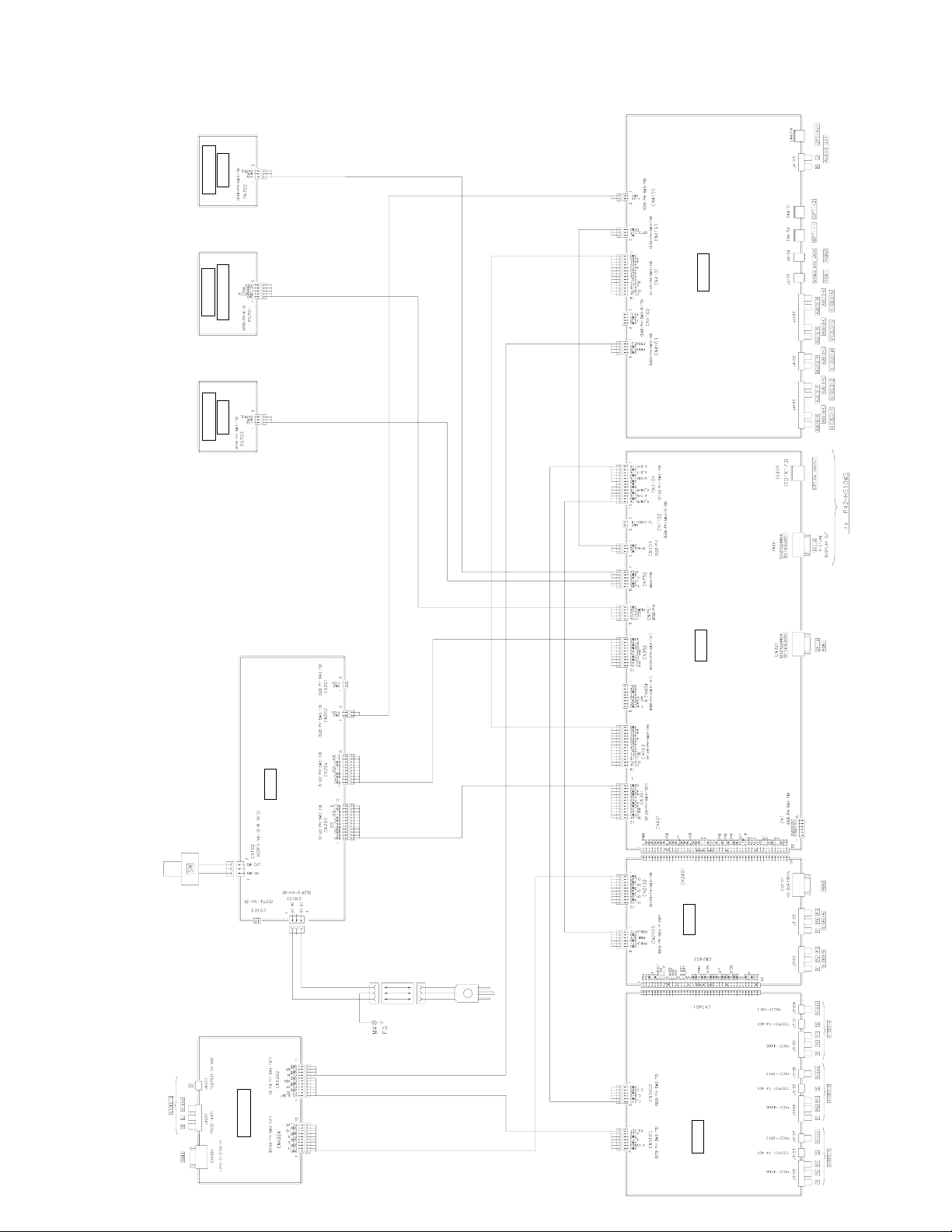
LED (L)
M02CNE
M02CNC
PHOTO / LED
LED (R)
M02CNF
M02CNA
AUDIO SELECTOR
- 69 -
Model : P-SU4H10W
M02DB
AC/DC POWER SUPPLY
INLET
M02CV
(SIGNAL PROCESSING)
MAIN / DIGITAL
M02CZ
VIDEO
SELECTOR
M02CND
TERMINAL
M02GL
Page 71

LED (L)
M02CNE
M02CNC
PHOTO / LED
LED (R)
M02CNF
M02CNA
AUDIO SELECTOR
- 70 -
Model : P-SU4H10E
M02DB
AC/DC POWER SUPPLY
INLET
M02CV
(SIGNAL PROCESSING)
MAIN / DIGITAL
M02CZ
VIDEO
SELECTOR
M02CND
TERMINAL
M02GM
Page 72

DISASSEMBLY
Model : P42HHS10W/E
1. Removing the Rear Case and layout of Main PCB
1. Remove the 19 screws and Rear Case.
A
* Layout of Main PCB.
C
B
A: Main Power PCB B: Audio PCB
C: Main PCB
- 71 -
Page 73

2. Removing the Main Power PCB
1. Remove the Rear Case.
2. Take away the insulator.
3. Disconnect the 11 circled connector.
4. Remove the 2 screws and Main Power
PCB.
* View after Main Power PCB removed.
- 72 -
Page 74

3. Removing the Main PCB
1. Remove the Rear Case and disconnect the
8 circled connectors.
2. Remove the 6 screws and Main PCB.
* View after Main PCB was removed.
- 73 -
Page 75

4. Removing the Audio PCB
1. Remove the Rear Case and disconnect the
2 circled connectors.
2. Remove the circled 4 screws.
* View after Audio PCB was removed.
- 74 -
Page 76

5. Removing the PDP Unit (1 of 3)
1. Remove the Rear Case and disconnect the
2 circled connectors.
2. Remove the 10 circled screws.
3. Remove the Base Frame from the Front
Case together with the panel and PCBs.
* View after removal of the Base Frame from
the Front Case.
- 75 -
Page 77

5. Removing the PDP Unit (2 of 3)
* View after the Front Case Panel Unit and
PCBs were removed.
4. Remove the Main Power PCB.
(To remove the Main Power PCB, refer to
the Page 72)
5. Disconnect the 2 circled connectors.
6. Remove the 10 circled screws and lift up
the Base Frame.
7. Disconnect the 1 circled connector and the
1 wire clamper.
- 76 -
Page 78

5. Removing the PDP Unit (3 of 3)
8. Remove the Base Frame together
with wires and other parts.
9. Disconnect the 7 circled connectors
1 screw and 2 wire clampers.
10. Remove the 12 circled screws.
* View after only the PDP Unit was removed.
* Replace the removed parts back in the correct
places when the PDP Unit is replaced.
- 77 -
Page 79

6. Removing the Bezel Front and Optical Filter (1 of 2)
1. Remove the PDP Unit and 8 circled
screws.
(To remove the PDP Unit, refer to
Page 75)
2. Pull the Bezel Front in the direction of
arrow.
(Repeat the same procedure on the other
3 locations.)
* View after the both top and bottom
Bezel Front removed.
3. Pull toward the direction of arrow.
(Remove the other side in a same
manner)
- 78 -
Page 80

6. Removing the Bezel Front and Optical Filter (2 of 2)
* View after Bezel Front was removed.
- 79 -
Page 81

7. Removing the Key Switch PCB
1. Remove the PDP Unit, 1 circled screw
and Key Switch Unit.
(To remove the PDP Unit, refer to Page
75)
2. Remove the 2 circled screws.
3. Remove the Key Switch PCB.
- 80 -
Page 82

Model : P42HHA10W/E
1. Removing the Rear Case (1 of 2)
A
E
B
D
C
1. Remove the 21 circled screws and remove
the Rear Case.
* Layout of Main PCB.
A: Main Power PCB
B: Audio PCB
- 81 -
Page 83

1. Removing the Rear Case (2 of 2)
C: Component PCB
D: Video PCB
E: Main/ Digital PCB
- 82 -
Page 84

2. Removing the Audio PCB
1. Remove the Rear Case and disconnect
the 2 circled connectors.
2. Remove the circled 4 screws and the
shield bracket.
3. Remove the circled 4 screws and Audio
PCB.
* View after Audio PCB was removed.
- 83 -
Page 85

3. Removing the Component PCB
1. Remove the Rear Case and disconnect the
1 circled connector.
2. Remove the 2 screws and Component PCB.
* View after Component PCB was removed.
- 84 -
Page 86

4. Removing the Video PCB
1. Remove the 3 circled screws.
2. Remove the Video PCB Unit.
3. Remove the 6 screws and Video PCB.
* View after Video PCB was removed.
- 85 -
Page 87

5. Removing the Main Digital PCB (1 of 2)
1. Remove the Rear Case, Component PCB
and Video Unit.
(Refer to Page 84, 85)
2. Disconnect the 9 circled connectors.
3. Remove the 11 circled screws and Main
Digital Unit.
4. Remove the shield bracket.
5. Disconnect the connection PCB.
- 86 -
Page 88

5. Removing the Main Digital PCB (2 of 2)
* View after Main Digital PCB was
removed.
- 87 -
Page 89

Model : P-SU4H10W/E
1. Removing the Tope Cover (1 of 2)
1. Remove the 2 circled screws.
2. Remove the 2 circled screws on the other
side.
A
3. Remove the 4 circled screws and Top
Cover.
B
- 88 -
Page 90

1. Removing the Top Cover (2 of 2)
E
C
D
A: Main Power PCB
B: Audio Selector PCB C: Terminal PCB
D: Video Selector PCB
E: Main Digital PCB
- 89 -
Page 91

2. Removing the Main Power PCB
1. Remove the Top Cover.
2. Disconnect the 5 circled connectors.
3. Remove the 4 circled screws and
Main Power PCB.
* View after Main Power PCB was removed.
- 90 -
Page 92

3. Removing the Audio Selector PCB
1. Remove the Top Cover and diconnect the
4 circled connectors.
2. Remove the circled 2 screws.
3. Remove the circled 7 screws and
Audio Selector PCB.
* View after Audio Selector PCB was
removed.
- 91 -
Page 93

4. Removing the Terminal PCB
1. Remove the Top Cover and Audio Selector
PCB.
(To remove the Audio Selector PCB, refer
to the Page 91)
2. Remove the 4 circled screws and the
shield bracket.
3. Disconnect the 2 circled connectors.
4. Remove the 6 circled screws and Terminal
PCB.
* View after Terminal PCB was removed.
- 92 -
Page 94

5. Removing the Video Selector PCB
1. Remove the Top Cover and Audio Selector
PCB.
2. Remove the Terminal PCB and disconnect
the 2 circled connectors.
(Refer to Page 91, 92)
3. Remove the 4 circled screws.
4. Remove the 10 circled screws and Video
Selector PCB.
* View after Video Selector PCB was
removed.
- 93 -
Page 95

6. Removing the Main Digital PCB (1 of 2)
1. Remove the Top Cover and Audio Selecror
PCB.
2. Remove the Terminal PCB and Video
Selector PCB.
(Refer to Page 91, 92, 93)
3. Disconnect the 7 circled connectors.
4. Remove the 3 screws and the shield
bracket.
5. Remove the 2 screws and the shield
bracket.
6. Remove the 6 circled screws and Main
Digital PCB.
- 94 -
Page 96

6. Removing the Main Digital PCB (2 of 2)
* View after Main Digital PCB was removed.
- 95 -
Page 97

7. Removing the LED PCB (1 of 3)
1. Remove the 1 circled screw.
2. Remove the 2 circled screws.
3. Unhook the 3 locations in arrow.
4. Unhook the 3 locations in arrow.
- 96 -
Page 98

7. Removing the LED PCB (2 of 3)
5. Disconnect the 3 circled connectors.
6. Remove the Front Cover.
7. Disconnect the 1 circled connector.
8. Remove the 2 circled screws adn LED
Unit.
9. Remove the 2 LED Covers.
- 97 -
Page 99

7. Removing the LED PCB (3 of 3)
10. Remove the LED PCB.
∗ View after LED PCB was removed.
- 98 -
Page 100

8. Removing the Interface PCB
1. Remove the Top Cover and Main Power
PCB.
(To remove the Main Power PCB, refer to
the Page 90)
2. Remove the 3 circled screws.
3. Disconnect the 2 circled connectors.
4. Remove the 2 circled screws and
Interface PCB.
∗ View after Interface PCB was removed.
- 99 -
 Loading...