

Page 1

P3PC-E807-01ENC2
FUJITSU TWAIN 32 Scanner Driver
Scanner Utility for Microsoft® Windows®
Version 9.12
User's Guide
For Use with Microsoft® Windows® 98, Windows® Me, Windows® 2000
and Windows
(* For Windows® 95 and Windows NT®,4.0, refer to Version 8.12 User’s Guide.)
®
XP
Page 2

Introduction
Thank you for purchasing the "Scanner Utility for Microsoft® Windows® V9.12".
This software contains a TWAIN-compliant image scanner driver (simply called "driver" in this
guide) and utilities.
This guide provides a description summary of the driver, as well as a description of the
installation method and procedures for appropriate use. Please read this guide before starting to
use the software.
In addition, read the README.TXT file on the CD-ROM for the latest information not
included in this manual.
In this guide, product names are abbreviated as follows:
®
• "Microsoft
• "Microsoft
Windows NT
• "Microsoft
• "Microsoft
• "Microsoft
• "Microsoft
When "Windows
and "Windows
Unless otherwise indicated, explanations refer to "Windows
®
NT
4.0," "Windows® Me", "Windows® 2000" and "Windows® XP" collectively.
[High Risk Activity]
The Customer acknowledges and agrees that the Product is designed, developed and manufactured as
contemplated for general use, including without limitation, general office use, personal use, household
use, and ordinary industrial use, but is not designed, developed and manufactured as contemplated for
use accompanying fatal risks or dangers that, unless extremely high safety is secured, could lead
directly to death, personal injury, severe physical damage or other loss (hereinafter "High Safety
Required Use"), including without limitation, nuclear reaction control in nuclear facility, aircraft flight
control, air traffic control, mass transport control, medical life support system, missile launch control in
weapon system. The Customer, shall not use the Product without securing the sufficient safety required
for the High Safety Required Use. In addition, PFU shall not be liable against the Customer and/or any
third party for any claims or damages arising in connection with the High Safety Required Use of the
Product.
Windows® 95 operating system": "Windows® 95"
®
Windows NT® Workstation operating system Version 4.0" and "Microsoft®
®
Server operating system Version 4.0": "Windows NT® 4.0"
®
Windows®98 operating system": "Windows®98"
®
Windows® 2000 Professional ": "Windows® 2000"
®
Windows® Millennium Edition": "Windows® Me"
®
Windows® XP": "Windows® XP"
®
95" "Windows® 98" "Windows NT® 4.0" "Windows® Me" "Windows® 2000"
®
XP" are referred to collectively, they are simply referred to as "Windows®".
®
95," "Windows® 98," "Windows
Copyright © PFU LIMITED 2003
i
Page 3

Trademarks
Microsoft, Windows and Windows NT are registered trademarks of Microsoft Corporation in
the United States and/or other countries.
Intel, MMX, Pentium are registered trademarks of Intel Corporation.
Adobe, Acrobat are the trademarks or registered trademarks of Adobe Systems Incorporated.
ISIS, QuickScan and their respective logos are registered trademarks of Pixel Translations, a
division of Captiva Software Corporation in the United States.
Adaptec is a registered trademark of Adaptec Inc.
EZ-SCSI is a trademark of Adaptec Inc.
Other product names are the trademarks or registered trademarks of the respective companies.
ii
Page 4

Organization
This manual explains how to install and use this driver, and how to use the TWAIN scanning
utility.
• Installation
This section explains the procedure for installing the environments in which this driver
may operate.
• Using the Driver
This section explains how to use the driver.
• Using the Gamma Pattern Editor
Use of the Gamma Pattern Editor is explained
• Using the Scanners and Cameras
This section explains about the property of “Scanners and Cameras”
• Troubleshooting
This section explains the possible causes of error messages and operation errors and the
corresponding recommended actions.
• Appendix
The appendix contains the specifications of image scanners.
iii
Page 5

Contents
1. Outline .............................................................................................. 1
1.1 Characteristics of this Driver...........................................................................1
1.2 Operating Environment...................................................................................1
1.3 Explanatory Notes ..........................................................................................2
1.4 Explanation of terms .......................................................................................3
2. TWAIN............................................................................................... 4
2.1 TWAIN ............................................................................................................4
2.2 TWAIN Application..........................................................................................5
3. Installation ....................................................................................... 6
3.1 Preparation .....................................................................................................6
3.2 Installing the Scanner Driver...........................................................................7
3.3 Uninstall........................................................................................................15
4. Using the Driver ............................................................................. 16
4.1 Selecting the Driver ......................................................................................16
4.2 Screen Configuration ....................................................................................16
4.2.1 Linkage to Image Processing Software Option....................................................17
4.3 Displaying Driver Information........................................................................18
4.4 Setting Information on Image Scanning........................................................19
4.5 Specifying Driver Operation..........................................................................27
4.6 Setting "Scanning Area" ...............................................................................29
4.7 Setting Options .............................................................................................30
4.7.1 Rotation ...............................................................................................................31
4.7.2 Job/Cache............................................................................................................34
4.7.3 Generic ................................................................................................................39
4.7.4 Imprinter (Endorser).............................................................................................40
4.7.5 Start Up................................................................................................................44
iv
Page 6

4.7.6 Filter.....................................................................................................................48
4.7.7 Compression........................................................................................................52
4.8 Setting Advance Options ..............................................................................53
4.8.1 Gray.....................................................................................................................54
4.8.2 Image Filter..........................................................................................................57
4.8.3 DTC .....................................................................................................................59
4.8.4 When Color (/Grayscale) is specified ..................................................................62
4.9 Setting the Setting Manager Options ............................................................67
4.10 Basic Scan Dialog ....................................................................................70
4.11 Download Pattern File ..............................................................................72
5. Using the Gamma Pattern Editor ................................................. 76
5.1 Start-up.........................................................................................................76
5.2 [File] menu....................................................................................................77
5.3 [Help] menu ..................................................................................................77
5.4 Gamma Pattern Editing ................................................................................78
6. Definition of Scanner and Camera Properties ............................ 79
6.1 Displaying Scanner and Camera Properties.................................................79
6.2 General Tab..................................................................................................79
6.3 Events Tab ...................................................................................................80
6.4 Diagnostic Tab..............................................................................................82
6.5 Device Information Tab.................................................................................83
6.6 Device Setup Tab .........................................................................................84
6.7 About Tab .....................................................................................................88
6.8 Color Management Tab ................................................................................88
6.9 Scanning by using “Scanner and Camera Wizard”.......................................89
7. Troubleshooting ............................................................................ 92
7.1 Error Messages ............................................................................................92
7.1.1 Messages from the TWAIN Driver .......................................................................92
7.1.2 Error messages relating to gamma correction pattern editing ...........................102
v
Page 7

7.2 Device Trouble Related to Operation..........................................................103
7.3 Device Trouble Related to Installation ........................................................104
8. Appendix ...................................................................................... 105
8.1 Relevant Image Scanner Specification .......................................................105
8.2 Maintenance Service ..................................................................................151
vi
Page 8

1. Outline
1.1 Characteristics of this Driver
• This driver complies with TWAIN regulations V1.9 (the latest version as of April 2003),
which are global standards for image scanners. The driver can be used in all TWAINcompliant applications.
• This driver also supports an image scanner that has the "double-sided scan" function. If
the application supports continuous scan, a double-sided document can be scanned.
1.2 Operating Environment
This driver can be used in the following systems:
[SCSI connection]
• A personal computer (recommended: Intel Pentium 100MHz or higher) on which one of
the following operating systems are installed
− Microsoft
− Microsoft
− Microsoft
− Microsoft
®
Windows
®
Windows® 98
®
Windows® 2000
®
Windows® XP
In case of Windows
Refer to ”FUJITSU TWAIN32 Scanner Driver Version 8.12 User’s Guide”.
®
• Adaptec
SCSI adapter or FUJITSU FMV SCSI adapter
®
®
95 or Windows NT® 4.0, FUJITSU TWAIN32 Version 8.12 is installed.
Millennium Edition
− In some cases, the driver may not operate with the above systems. Please check in
advance with your place of purchase.
− Notes are provided on the accepted SCSI adapters in README.TXT, which is
included in the installation media. Please read these notes before use.
• This driver has the following hardware requirements:
− RAM: 32 MB or more (a minimum of 64 MB is recommended)
− Available hard disk space: 10 MB or more (excluding the area for storing images)
− CD-ROM drive (required for installation)
• Mouse (recommended)
[USB connection]
• A personal computer (recommended: Intel Pentium 100MHz or higher) on which one of
the following operating systems are installed
– Microsoft
− Microsoft
− Microsoft
®
Windows
®
Windows® 98
®
Windows® 2000
®
Millennium Edition
1
Page 9

− Microsoft
®
Windows® XP
• USB port
• RAM: 32 MB or more (a minimum of 64 MB is recommended)
• Available hard disk space: 10 MB or more (excluding the area for storing images)
• CD-ROM drive (required for installation)
• Mouse (recommended)
1.3 Explanatory Notes
The descriptions in this manual are prepared based on the following rules:
◊ Menus and buttons
The menus and buttons used in the program description are enclosed in [].
Example: [File] menu
[OK] button
◊ Keyboard
The keytop indications comply with the standard keyboard of the Fujitsu FMV series.
Major differences between the Fujitsu FMV keyboard and other keyboards are shown
below.
FMV keytops Other possible keytops
Alt Previous screen, GRPH
Ctrl CTRL
Esc ESC
Enter Return,
Shift SHIFT
Back space Backspace, BS
F1 PF1, f-1
◊ Terms related to mouse operation
Terms related to major mouse operations are explained below.
Click: To press and release the mouse left button
Double click: To quickly press the mouse left button twice
Drag: Move the mouse while keeping the mouse left button pressed
2
Page 10

◊ Notes on operation procedures
If some menus need to be operated in a certain order, the procedural order is described as
follows:
[A] - [B] - [C]
In accordance with this description, operation [A] is executed first, followed by [B] and [C]
in that order.
◊ Figures
Figures and screen operations in this guide refer to Microsoft
also followed when using other operating systems.
Note that the expressions may vary with the type of scanner connected.
1.4 Explanation of terms
◊ IPC option board
IPC-2/2D in this guide refers to the IPC-2 and IPC-2D image processing circuit.
IPC-3/3D in this guide refers to the IPC-3 and IPC-3D option board.
IPC-4D in this guide refers to the IPC-4D option board.
®
Windows® 2000. They are
3
Page 11

2. TWAIN
2.1 TWAIN
TWAIN is the specification that defines the standard software protocol and application
programming interface (API) for data exchange between a software application program and an
image input device such as the image scanner.
[TWAIN development background]
In the past, development of a new scanner inevitably required the development of a compatible
driver and a sample (demonstration) program exclusively designed for the new scanner. As the
scanner is upgraded, the driver may need to be upgraded as well to maintain its compatibility
with the upgraded scanner. Therefore, the use is most likely to be restricted to one specific
scanner model to avoid the complication of learning new operation methods and replacing the
peripheral driver, etc., involved in scanner replacement.
In view of the incompatibility among different scanners and peripheral equipment and the
accompanying inconvenience, there was a demand for standardization of the related hardware
and software, and TWAIN was established as a result.
The user may now choose among all the input devices and software (driver or application
programs) conforming to the TWAIN standard, and configure a most suitable system for
himself, without being restricted to the products of a certain series or a certain manufacturer.
4
Page 12
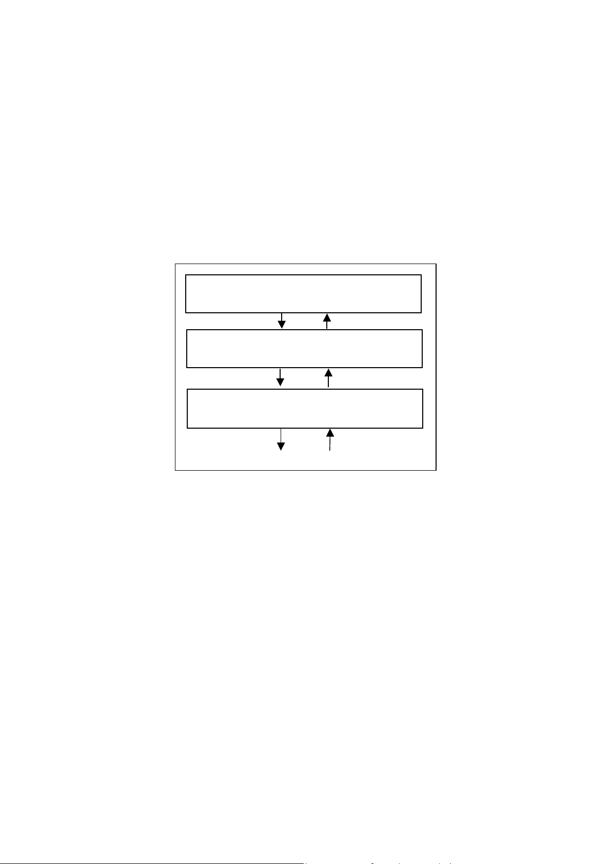
2.2 TWAIN Application
TWAIN mainly applies to the following three software components:
Application software
Source manager
Source
The components are related to each other as shown below.
Application software
(photo retouching software, etc)
Source manager
(TWAIN.DLL/TWAIN_32.DLL, etc)
Source
(Image scanner control of the driver, etc)
Image scanner, etc.
Figure TWAIN Application
5
Page 13

3. Installation
3.1 Preparation
1. Make sure that the operating system (OS) is installed correctly.
2.
In case of the SCSI connection, confirm that the SCSI adapter is connected to your PC and
operating correctly.
In case of the USB connection, confirm that the USB port is installed in your PC.
3. Confirm that the hard disk that is the installation destination has enough free space.
4. If old version FUJITSU TWAIN 32 Driver has already been installed on your PC, uninstall
it before installation.
When uninstalling old versions, select [Control Panel] – [Add or Remove Programs] on the [Start]
menu and uninstall “Scanner utility for Microsoft Windows”.
5. Turn off your PC.
6. Connect the scanner to your PC.
Refer to “Operator’s Guide” of the scanner for scanner connection.
6
Page 14
3.2 Installing the Scanner Driver
The Windows® XP screen samples are shown below. The screen and operations will differ
slightly depending on the OS that is being used.
1. Turn on the scanner.
2.
Turn on your PC and Log on to Windows
When using Windows® 2000 or Windows® XP, log on as an administrator.
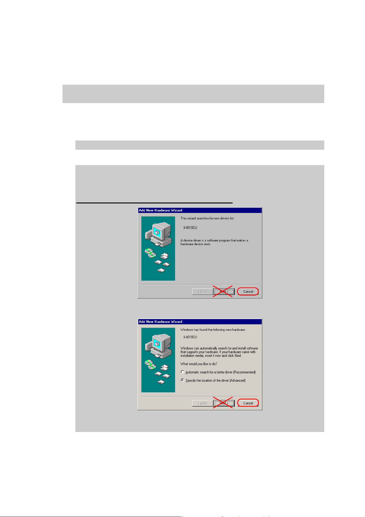
The scanner may be detected automatically, and the "Found New Hardware Wizard" (or
“Add New Hardware Wizard”) window is displayed.
In this case, click [Cancel] button to close this Wizard window.
(* Depending on the OS, the window displayed differ.)
®
.
In case of Windows® 98
In case of Windows® Me
7
Page 15
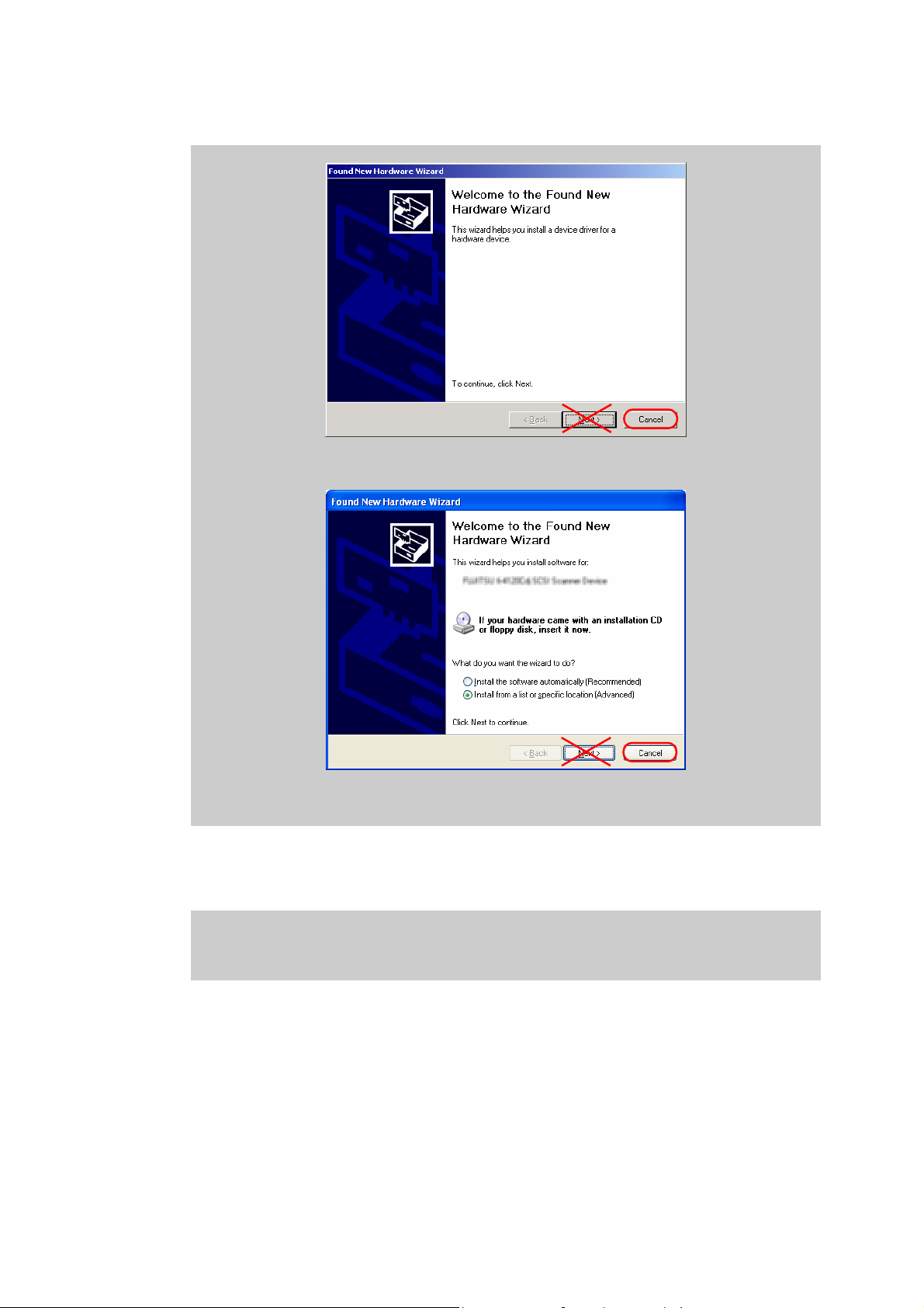
In case of Windows® 2000
In case of Windows® XP
3. Insert the Setup CD-ROM into the CD-ROM drive.
<SETUP DISK START UP SCREEN> is displayed.
This Dialog is not displayed automatically when "Auto play" setting of your PC is off.
In this case, please run “Install.exe” in this CD-ROM directly using “Explore” or “My
computer”.
8
Page 16
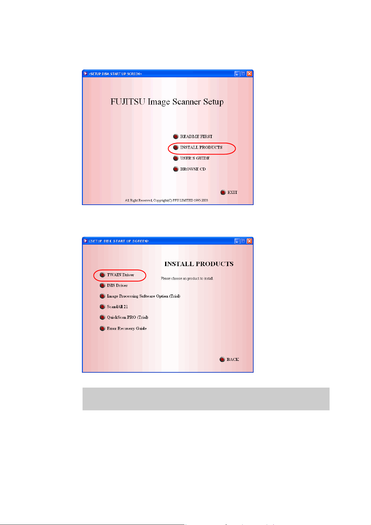
4. Click [INSTALL PRODUCTS].
(* Depending on the scanner model, the different screen may appear.)
5.
Click [TWAIN Driver]
(* Depending on the scanner model, the different screen may appear.)
Depending on the scanner model, the screen which confirms whether “Error Recovery
Guide” is installed or not is displayed.
In this case, click [OK] button, and install Error Recovery Guide.
9
Page 17
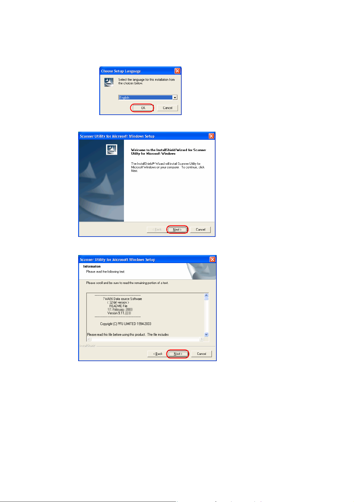
6. Select the language you use in [Choose Setup Language], then click [OK] button.
7. Click [Next >] button.
8. Read the information of README File, and then click [Next >] button.
10
Page 18
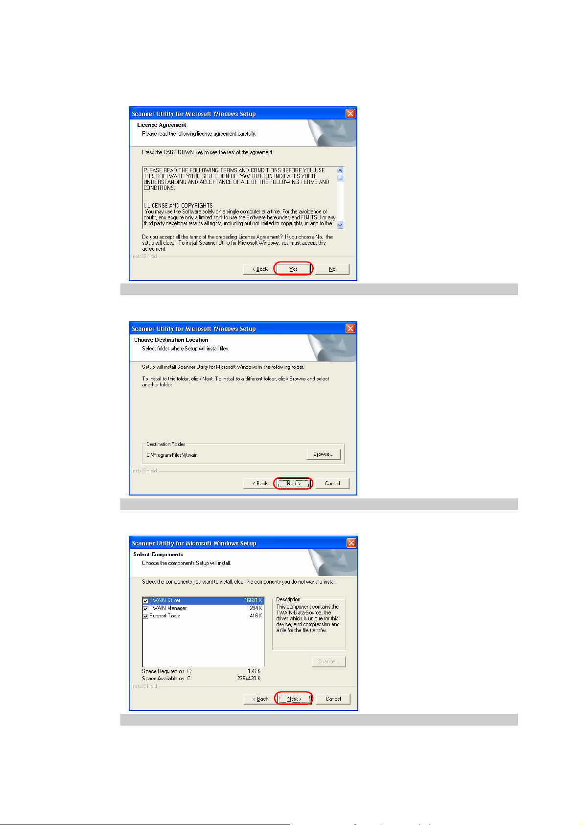
9. Read the License Agreement carefully, and then click [Yes] button if you agree.
If you click [No] button, the installation is stopped.
10. Confirm Destination Folder, and then click [Next >] button.
Usually, it is not necessary to change Destination Folder.
11. Confirm Components you install, and then click [Next >] button.
Usually, it is not necessary to change the selection of Components.
11
Page 19
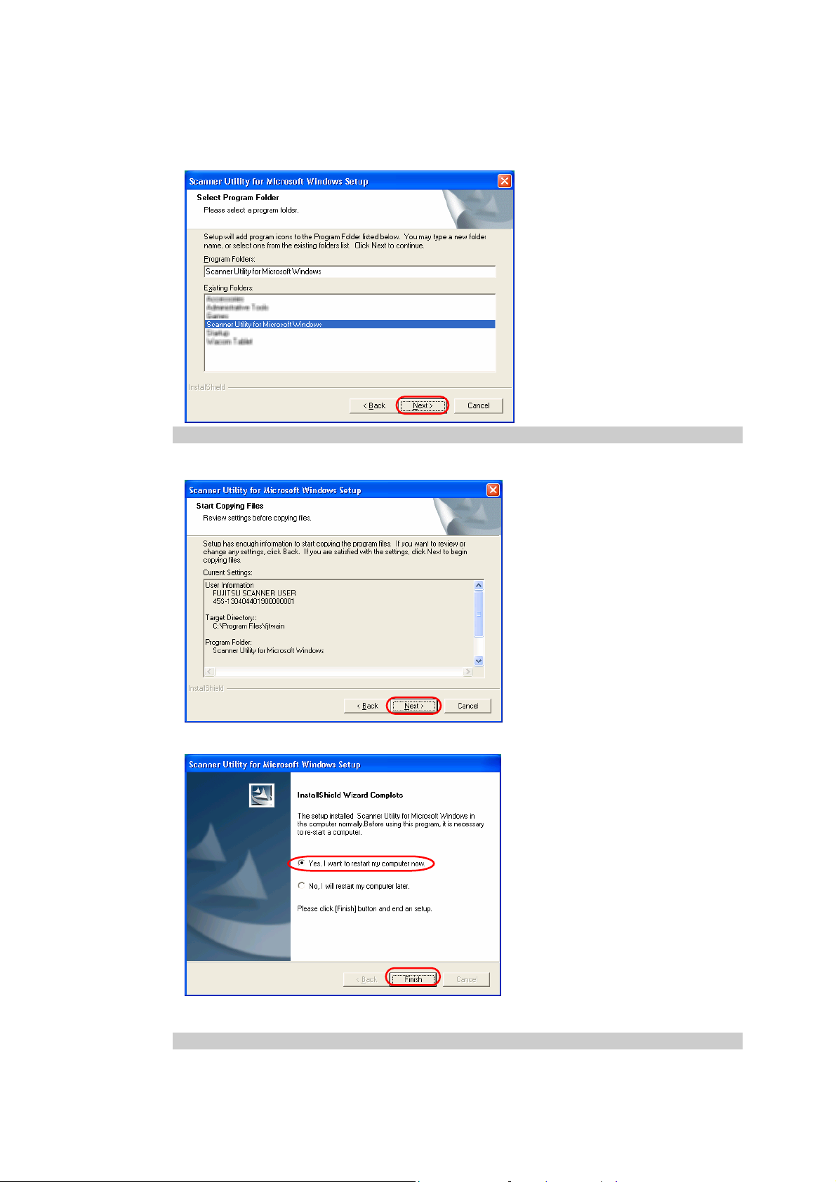
12. Confirm Program Folder, and then click [Next >] button.
Usually, it is not necessary to change the Program Folder’s name.
13. Click [Next >] button, and copying files is started.
14. Select “Yes, I want to restart my computer now”, and then click [Finish] button.
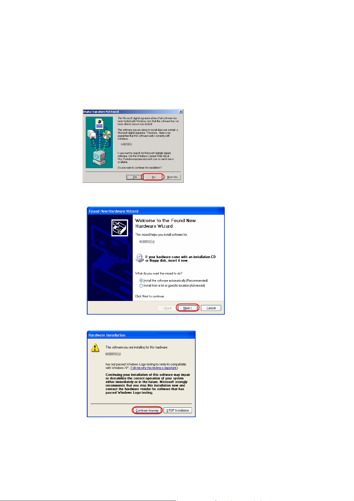
15. After the restart, the scanner is detected.
Depending on the OS, the following operations may be required.
12
Page 20
In case of Windows
®
98
There is a request to insert a disc. When this happens, insert the Windows® 98 CD-ROM in
your CD-ROM drive.
In case of Windows
[Digital Signature not Found] is displayed, click [Yes] button.
®
2000
In case of Windows
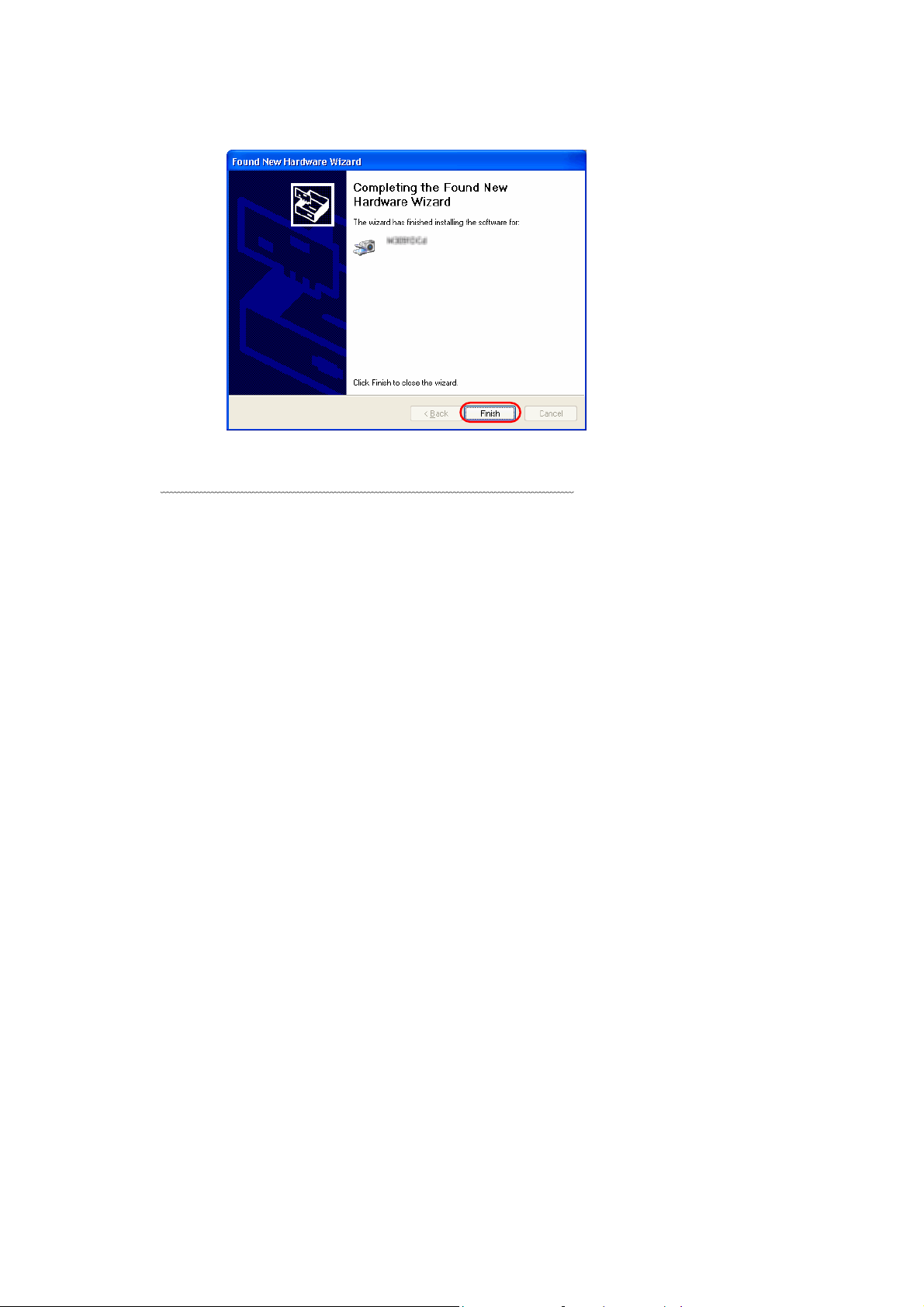
1) [Found New Hardware Wizard] is displayed, click [Next >] button.
®
XP
2)
If [Hardware Installation] is displayed, click [Continue Anyway] button.
3)
Click [Finish] button when the installation is finished.
13
Page 21
Now, the installation of scanner driver is completed.
14
Page 22

3.3 Uninstall
The uninstall process removes the software and returns the hard disk to its pre-installation state.
When you want to remove this scanner driver program from your PC, uninstall by the following
procedures.
Turn on your PC and Log on to Windows
1.
When using Windows® 2000 or Windows® XP, log on as an administrator.
2. Close all of the applications on Windows®
3.
Select [Control Panel] from [Start] menu.
The [Control Panel] is displayed.
Double-click [Add/Remove Programs] from the icon list of the [Control Panel].
4.
The properties of [Add/Remove Programs] is displayed.
5.
Select "Scanner Utility for Microsoft Windows" from the "Install/Uninstall" list.
6.
Click [Add/Remove] button.
When the confirmation dialog is displayed, click [OK] button if you are ready to uninstall.
7.
8.
When uninstallation is completed, click [Finish] button.
Image files that have been scanned and saved will not be deleted.
If other TWAIN-compliant applications and drivers have been installed and you are asked
whether or not to delete files shared with them such as the TWAIN Manager, select [NO] to
avoid deleting them.
®
.
The screen and operations may differ slightly depending on the OS that is being used.
<In case of Windows® XP>
- [Add/Remove Programs] [Add or Remove Programs]
- [Add/Remove] button [Change/Remove] button
15
Page 23
4. Using the Driver
4.1 Selecting the Driver
To use this driver from the TWAIN application, select "FUJITSU <Product ID>" from the
TWAIN data source (driver) selection screen. For general application, the data source selection
screen is displayed by selecting the [Select Scanner] or [Acquire ...] menu. Refer to the
instruction manual for the application used for details.
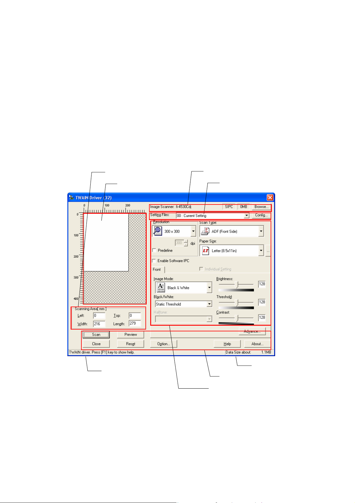
4.2 Screen Configuration
Scanning Area settings
Preview window
Image scanner name
Setting file name
Message line
Figure Main Dialog
16
Data size
Button control
Image scan related data
Page 24
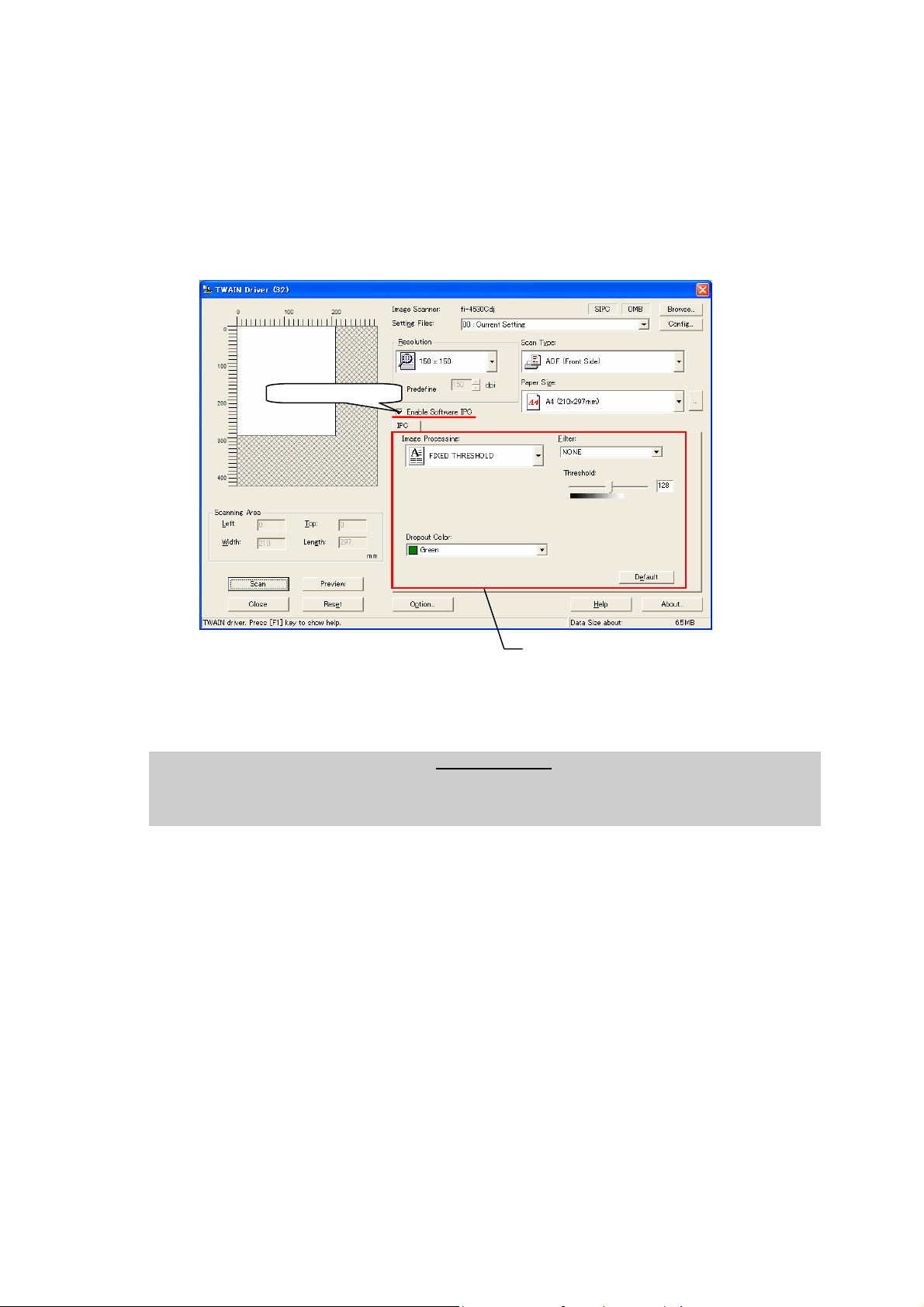
4.2.1 Linkage to Image Processing Software Option
When the “Enable Software IPC” checkbox is marked after installation of “Image
Processing Software Option” (sold separately), there appears setting items of Image
Processing Software Option in a part of the Setting Window for TWAIN Driver.
Mark this checkbox.
Setting items of “Image Processing
Software Option” are displayed here.
You can change the settings of Image
Processing Software Option here.
• The ”Image Processing Software Option” version 2.1 or later is required for settings on the window of
TWAIN Driver.
• For details about the Image Processing Software Option, refer to the “Image Processing Software
Option User’s Guide”.
The following pages contain the explanation and operation description for each part.
17
Page 25
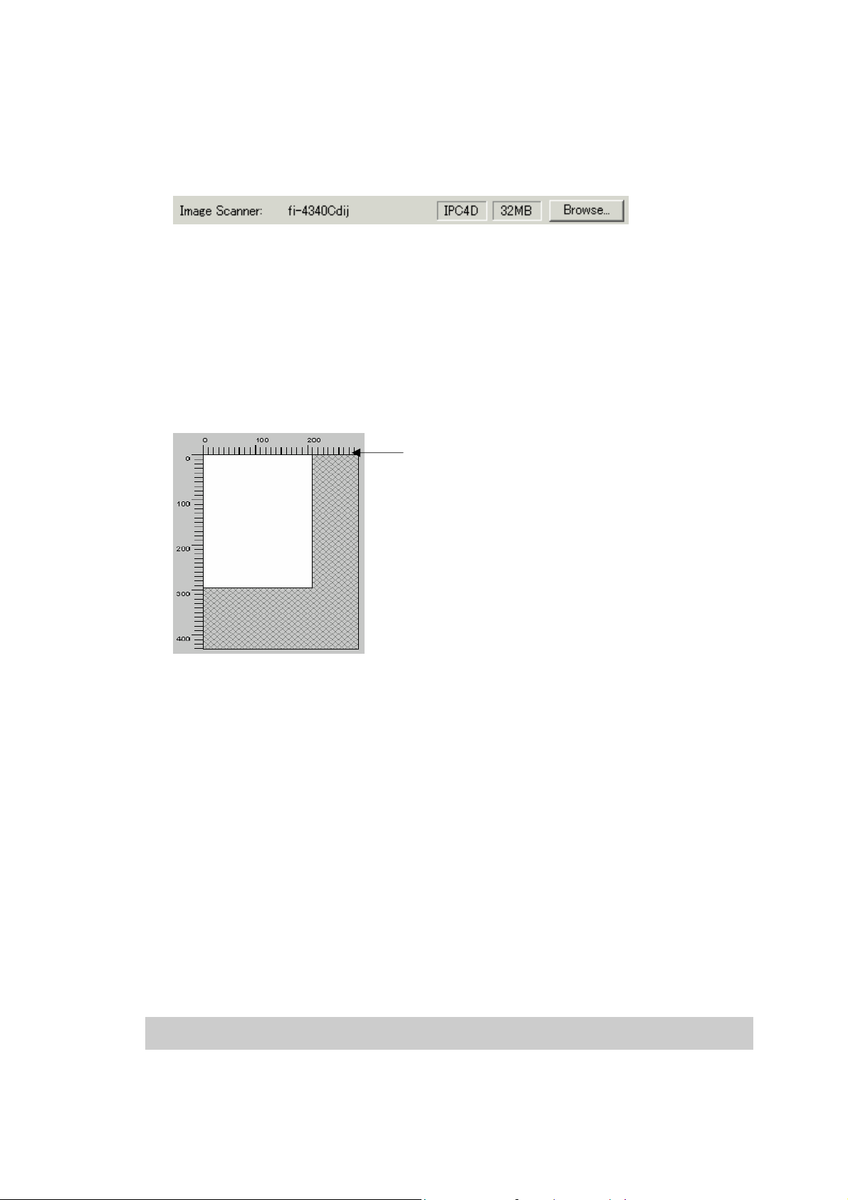
4.3 Displaying Driver Information
♦ Image scanner name
The model name, option port name, and capacity of internal scanner memory (in units of
megabytes) of the connected image scanner are displayed.
If no image scanner is connected, this field is blank.
The type of IPC option board is displayed if an image-processing option board is installed
in the scanner.
IPC-3/3D may not be detected normally, as it is affected by the version number of the
machine type and device. In this case, "IPC2" is displayed.
♦ Preview window
Ruler
The preview window is used to display the temporary image of read data and for setting the
"Scanning Area."
For settings, see "Scanning Area" later in this manual. Also see the description of the
[Preview] button later in this manual.
♦ Ruler
The large divisions are labeled as "Unit". The scale also varies with the selected scanner.
♦ Message line
The message line is the bottom line of the dialog in which a brief explanation of an input
item or a setting item is displayed when the mouse cursor is moved over the item.
♦ Data size
The approximate amount of data per image when data is scanned in the present option.
Note.
This value is the amount of uncompressed data. The size of the stored file will differ from this
value and is usually smaller if image compression is chosen and the image is compressed.
18
Page 26
4.4 Setting Information on Image Scanning
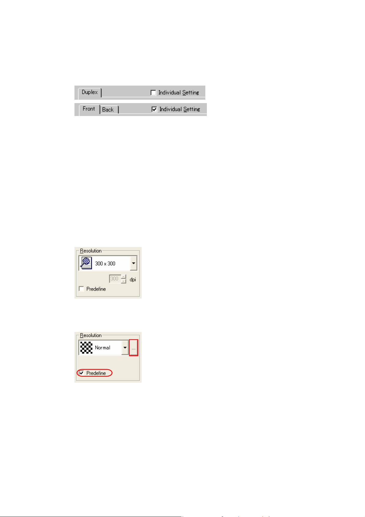
♦ Current side
When a scanner that allows duplex scanning is used, specifies the page which sets the
image scanning information.
To scan using the same settings as those for "Front side" and "Back side," clear the checks
in the "Individual Setting" checkbox on the "Front" and "Back" tabs. A single "Duplex" tab
will be displayed at the left so that the same image scanning information can be set for
"Front side" and "Back side."
To scan using different settings for "Front side" and "Back side," check the "Individual
Setting" checkbox on the "Front" and "Back" tabs. Two tabs, "Front" and "Back," will be
displayed at the left. Select each tab and enter the desired settings.
This is only effective when ADF (Duplex) is selected for the method of paper feed. For
scanner types which permit duplex scanning, see "Relevant Image Scanner Specification"
in the Appendix.
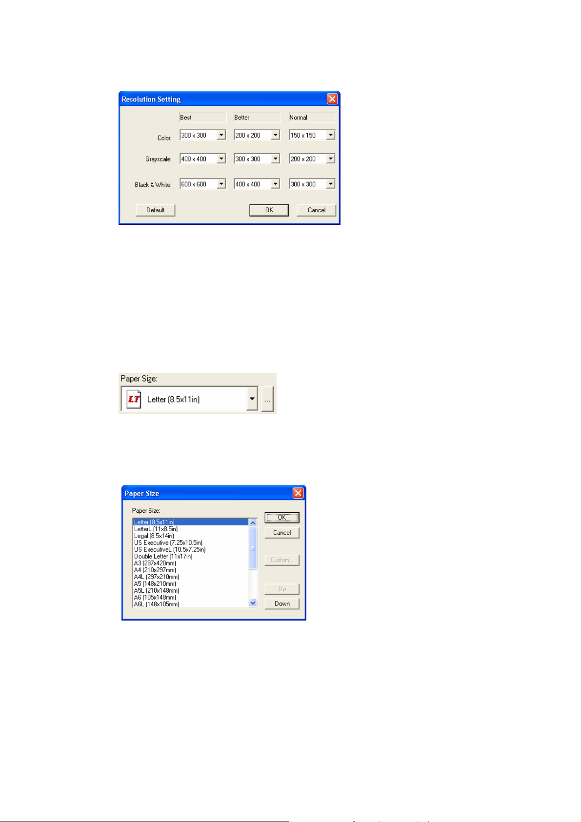
♦ Resolution
Specifies the number of pixels (dots) per inch.
Select a predefined resolution or [Custom] from the list.
[Customize] enables detailed settings by a pixel unit.
By marking [Predefine] checkbox, you can select one from three predefined settings as
[Normal], [Fine], [Super Fine] to scan documents instead of configuring settings by
yourself.
Otherwise, you can change the details of the predefined settings on the [Resolution Setting]
window, which appears when you click on the […] button.
19
Page 27
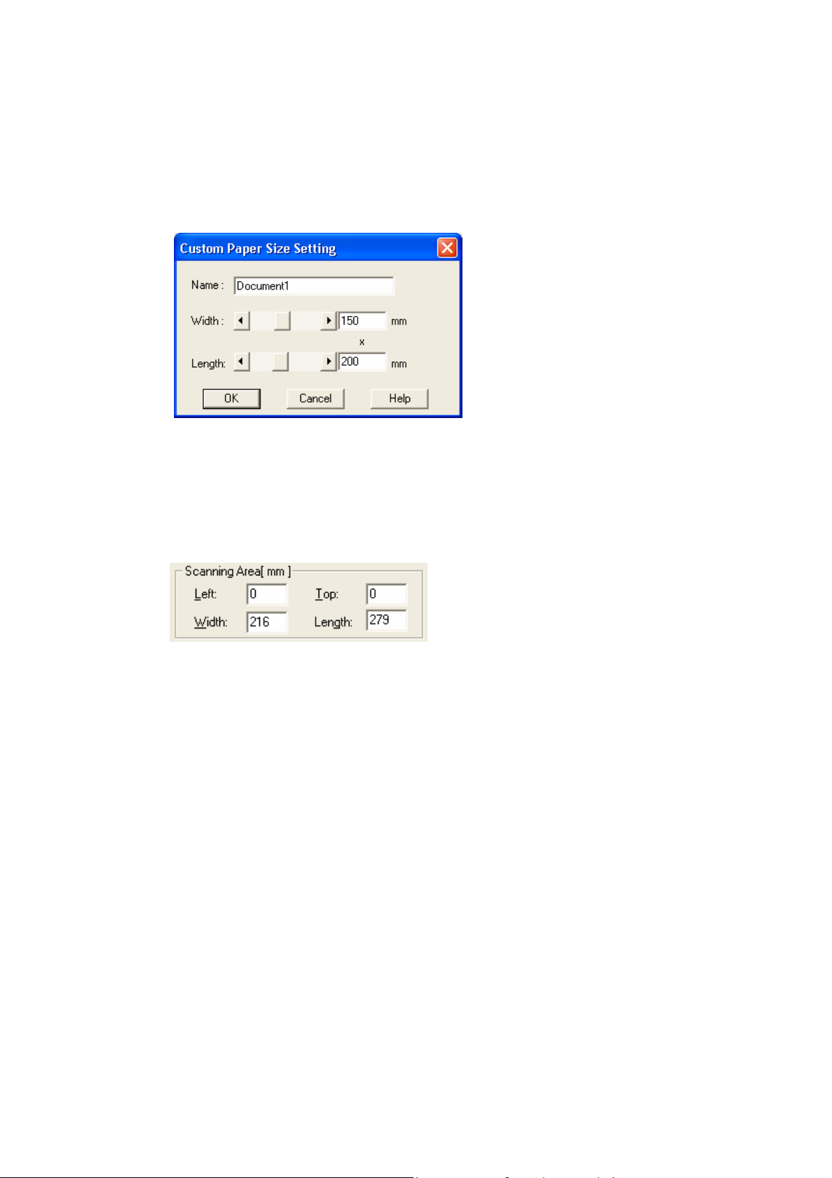
Resolutions for Image modes (“Color”, “Grayscale”, and “Black &White”) of the each
predefined settings are changed corresponding to the selection of the Image Type.
* Click [Default] button to return the resolutions to the default value.
High resolution produces finer images, meanwhile requires more memory that leads to
longer scanning time.
The supported resolution depends on the type of scanner and the options installed.
Refer to "Relevant Image Scanner Specification" in the Appendix.
♦ Paper Size
Specifies a document size for scanning.
Select a standard size or [Custom] size (can be registered up to three) from the list.
Window for customizing the paper size will appear when you click on […] button besides
the list. On this window, you can change the order of the paper size in the list.
[Custom] button : Used for configuration of a custom size.
[Up] button : Used for shifting the order of the selected document size upward.
[Down] button : Used for shifting the order of the selected document size downward.
You can register up to three sizes as the customized document sizes.
20
Page 28
[Custom Paper Size Setting] window will appear when you click the [Custom] button.
Enter the size of the document to be scanned. (When entering the size, specify the paper
size by width x length to the scanning direction.)
Some paper sizes may not be accepted by your device. Refer to "Relevant Image Scanner
Specification" in Appendix.
Name :
Enter the name of the customized setting to be displayed in the list.
Width, Length
: To specify a custom paper size, use the scroll bar or enter the paper
size directly. The unit specified in [Option]-[Generic]-[Unit/Scaling]
will be applied to the unit in this window.
♦ Scanning Area
Specifies the start position, width and length for the image scan. The maximum allowable
size is the paper size selected previously.
In addition, the minimum size is 1.000 inch, 26 millimeters, or pixels (number of dots per
inch) according to the unit that has been set.
"Left": The left end of the scan area on the scanned document (X coordinate)
"Top": The top end of the scan area or the scanned document (Y coordinate)
"Width": The width of the scan area
"Length": The length of the scan area
These values are related to one another in the following way:
0 ≤ left end coordinate < (paper width - minimum scan area size)
0 ≤ top end coordinate < (paper length - minimum scan area size)
Minimum value ≤ width ≤ (paper width - left end coordinate)
Minimum value ≤ length ≤ (paper length - top end coordinate)
21
Page 29

♦ Scan Type
Selects the feeding device.
The image scanner uses a document bed called the flat bed as well as an automatic
document feeder (ADF) for feeding scanned document. The ADF usually enables the
documents to be scanned only once. The flat bed allows scanning the same documents
repeatedly.
Flat bed
Scans a document placed on the flat bed of the device.
ADF (Front Side)
Scans the documents on the device's automatic document feeder (ADF). Here, only the
front sides are scanned.
ADF (Duplex)
To scan both the front and the back of a page, select this option.
If this option is selected, the documents are scanned in the "front to back to front to
back ..." order.
This option can be used only for scanner models that support duplex scanning.
The "Duplex Function" requires that the calling application supports "continuous scan."
If the application does not support "continuous scan," only the data for the front side of
the page is passed to the application.
Some scanner models do not support this option. See "Relevant Image Scanner
Specification" in the Appendix.
Long page (Front Side)
Scans a document longer than the paper size which can be specified by [Paper Size].
In this case, only the front sides of documents are scanned.
When this option is selected, the "Paper Size Setting" dialog box opens. Specify the
size of the document to be scanned.
* While the "Long page" is specified, the preview window cannot be displayed and the
scanning area cannot be specified.
* In case of some scanner models, while the "Long page" is specified, color and grayscale
settings can not be selected in [Image mode].
(Refer to “Relevant Image Scanner Specification” in the Appendix.)
* Depending on the scanner, [Resolution] setting should be set to less than 400 dpi.
* The "Long page" is not displayed in the [Scan Type] dropdown list if not supported by
the device. See "Relevant Image Scanner Specification" in the Appendix.
Long page (Duplex)
Scans a document longer than the paper size which can be specified by [Paper Size].
If this option is selected, the documents are scanned in the "front to back to front to
back…" order.
22
Page 30
ADF (Back Side)
Scans the documents on the device's automatic document feeder (ADF).
Here, only back sides are scanned.
Note.
To specify duplex scanning, the number of copies designated should be based on the
number of pages, not the number of paper sheets. In other words, one original with a front
and back is regarded as two pages.
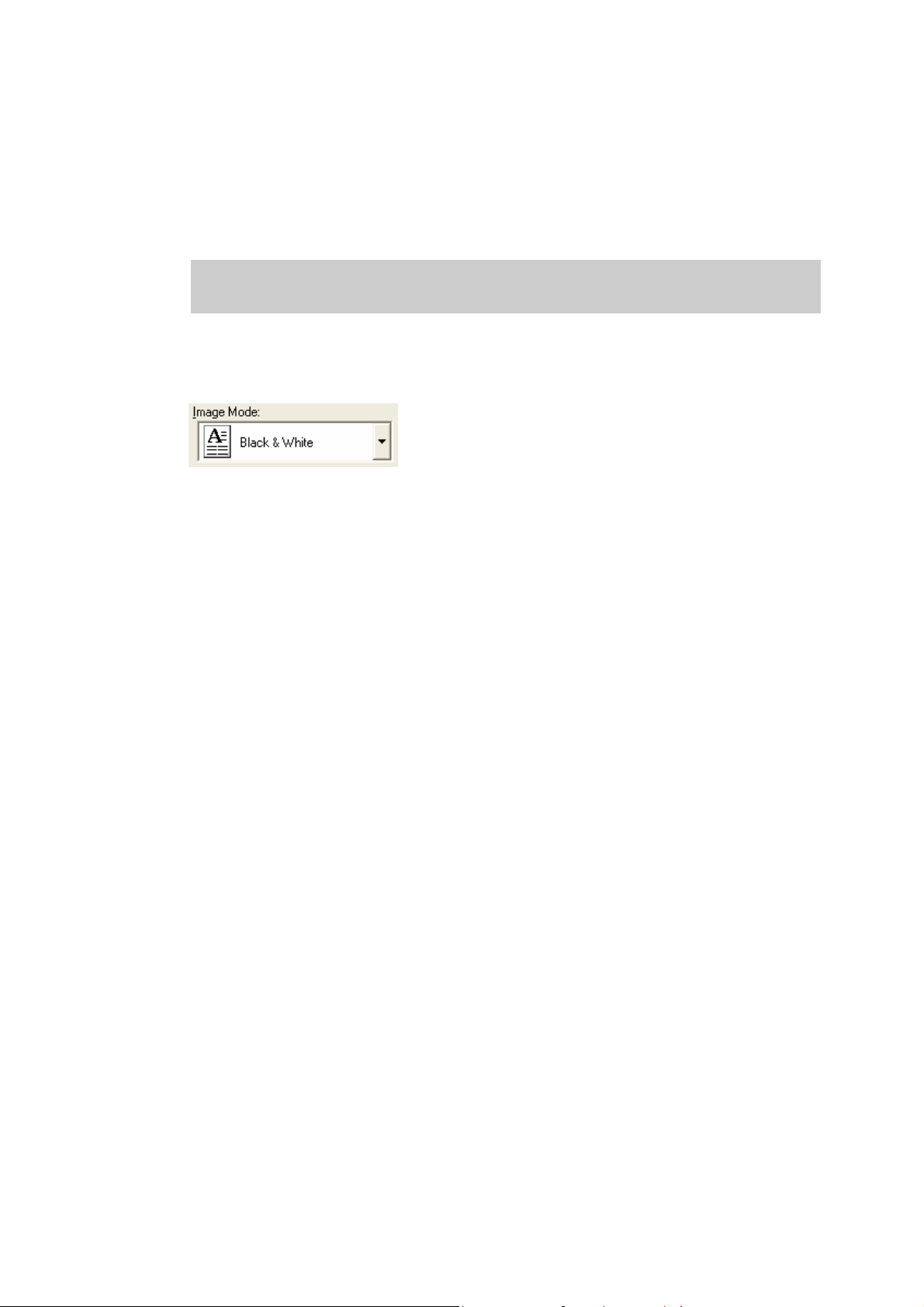
♦ Image Mode
Selects an image mode for scanning the image.
Select a corresponding image mode from the list.
Black & White
Scans data by using the fixed threshold binary, black-and-white. Distinguishes black
from white by the setting in the "Threshold" of "Scanning Parameter". This scanning
mode is suitable for scanning line drawings and text documents.
Halftone (Dither)
Scans data using the halftone processing, with dithering or error diffusion. Uses the
patterns set in "Halftone" to simulate data in black-and-white. Selection of built-in
dithered patterns or error diffusion (not supported by some device models) is allowed.
This scanning mode is suitable for scanning images containing light and shadow such
as a photograph.
Gray scale
Scans data using 256-level monochrome gray scale. Light and shade in photographs
can be represented with greater fidelity. This scanning mode employs far more
memory than the Black & White mode.
Some versions of the scanner do not support this scanning mode. For details contact the
retail store where the device was purchased.
Automatic separation
Scans data distinguishing line drawing from photograph image.
If this option is selected, the line drawing part is scanned using "Black & White," and
the photograph part is scanned using "Halftone". This information is most suitable for
documents containing both photographs, and line drawings or text.
Some scanner models do not support this option. See "Relevant Image Scanner
Specification" in the Appendix.
SEE (Selective Edge Emphasis)
Scans data using the halftone processing and emphasizes line drawings and text. This
option is most suitable for emphasizing only text of documents containing both
photographs and text.
Some scanner models do not support this option. See "Relevant Image Scanner
Specification" in the Appendix.
23
Page 31

24bit Color
Scans data using 24 bits color. This mode is suitable for scanning color photograph
and employs far more memory that Gray scale mode.
Only color scanner models support this option. See "Relevant Image Scanner
Specification" in the Appendix.
256 Color
Scans data using 256 colors.
Data size is smaller than "24 bit Color" selected.
Please note that the image quality of "256 Color (8 bit)" is inferior to the case of "24 bit
Color ". Choose "24 bit Color" for higher quality.
Only color scanner models support this option. See "Relevant Image Scanner
Specification" in the Appendix.
8 Color
Scans data using 8 colors.
Data size is smaller than “256 Color” selected.
Please note that the image quality of "8 Color" is inferior to the case of "24 bit Color"
and "256 Color (8 bit)". Choose "24 bit Color" for higher quality.
Only color scanner models support this option. See "Relevant Image Scanner
Specification" in the Appendix.
♦ Black & White
Specifies the processing method when "Black & White" is specified in "Image Mode".
Static Threshold
Executes simple binary processing based on the "Threshold" setting.
SDTC, DTC mode
To enable the auto binary function of the image scanner, specify this option.
If this option is selected, the "Threshold" setting will be disabled.
In addition, auto binary has two modes: " SDTC Mode" and "DTC Mode". These
modes can be set using the "Advance" dialog box.
"DTC Mode", however, is limited to the image processing options. Therefore, only
scanner models that have image processing options support "DTC Mode". See
"Relevant Image Scanner Specification" in the Appendix.
SDTC mode (Floating Slice)
This option enables scanning and fine binary processing for documents whose
backgrounds are other than white such as newspapers.
Some scanner models do not support this option. See "Image Scanner Specification" in
Appendix.
24
Page 32

♦ Halftone
Select the halftone pattern for halftone scanning from the built- in pattern list.
Select the desired halftone pattern for displaying the obtained image. This setting is
effective when "Halftone" or "Automatic Separation" is selected in "Image Mode".
Some scanner models do not support this function. See "Relevant Image Scanner
Specification" in Appendix.
Dither Pattern 0
Executes pattern processing that is suitable for scanning a dark photograph.
Dither Pattern 1
Executes pattern processing that is suitable for scanning a dark-colored document
containing both text and photographs.
Dither Pattern 2
Executes pattern processing that is suitable for scanning a light photograph.
Dither Pattern 3
Executes pattern processing that is suitable for scanning a light-colored document
containing both text and photographs.
Download Pattern
Executes processing using the dithered download pattern specified in the dithered
download file (described later). Some scanner models do not support this function.
See "Image Scanner Specification" in Appendix.
Error Diffusion
Error Diffusion minimizes the difference between the pixel density of the scanned
image and the pixel density of the printed image to create better reproduction of a
scanned photograph.
Some scanner models do not support this function. See "Relevant Image Scanner
Specification" in Appendix.
25
Page 33

♦ Scanning Parameters
For fine scan adjustments.
Since there is no fixed set of values, set by trial and error.
◊ Brightness:
Sets the brightness of the overall image.
Specify the brightness with a number in the range of 1 (bright) to 255 (dark).
To darken the overall image, increase the value of the setting. To brighten the overall
image, decrease the value.
This parameter can be set if "Halftone" or "Automatic Separation" is selected for
"Image Mode."
◊ Threshold:
Sets the threshold value by which the black and the white of black-and-white images
are distinguished. Specify a number in the range of 1 (bright) to 255 (dark). This
parameter can be set only if "Black & White" is specified for "Image Mode."
In addition, if "DTC mode" is selected, the scanner will automatically use the
appropriate threshold value. As a result, the set value cannot be changed.
If the light color in the scanned document is read as black, increase the threshold value.
To eliminate light- colored areas in the scanned document, decrease this value.
◊ Contrast:
Sets the contrast of light and shadow in a scanned image.
Specify the contrast with a number in the range of 1 (low [soft]) to 255 (high [sharp]).
The contrast can be set if "Gray Scale" is selected in "Image Mode."
If this value is increased, the dark part of the image is shown darker and the light part is
shown lighter.
Some scanner models do not support this function. See "Relevant Image Scanner
Specification" in Appendix.
26
Page 34

4.5 Specifying Driver Operation
♦ [Preview]
Scans in a preliminary image based on set values, and displays the image in the preview
window.
Before actual scanning, the preview function can be used to display the entire document for
specifying the desired scan area.
Some models do not support this function. See "Relevant Image Scanner Specification".
♦ [Scan]
Scans the specified scan range based on set values.
The following "progress indicator" is displayed during scanning to show the progress of the
scan operation. To stop scanning, click the [Cancel] button.
The character string indicates the data transfer mode used between the driver and the
application.
Progress indicator
♦ [Close] / [OK]
Closes the dialog box without scanning.
If a setting is changed, the changed setting is saved in the initial value file.
♦ [Reset]
Restores the current setting values to the status immediately after the window is opened.
27
Page 35

♦ [Help]
Displays online help. When the [F1] key is pressed, help information regarding the item on
which the cursor is placed is displayed.
Note
Depending on the application used help information may not be displayable with the [F1] key.
This is because the driver operation is controlled through the application and the [F1] key may
be used differently in each application program.
Help information can be displayed by pressing the [F1] key while holding down the [Ctrl] or
[Shift] key.
♦ [Option]
Displays the "option dialog" for setting device-specific functions. See Section 4.7, "Setting
Option" described later.
♦ [Advance]
Displays the "advance dialog " for settings related to color variance and image processing.
♦ [Config]
Displays the "basic scan dialog" for managing the settings file and for setting simple scan
dialog switching.
♦ [About]
Express the version of this driver by clicking this button.
28
Page 36

4.6 Setting "Scanning Area"
Specify the scanning area in the preview window as follows:
Setting:
1. Press the left mouse button to specify the origin (top left corner) of the scanning area.
(The cursor appears as a "+".)
2. Drag the mouse to show the outline of the scanning area. (As the cursor moves, a range
frame is shown.)
3. Release the left mouse button again to set the range (bottom right corner) of the
scanning area.
Movement:
1. Move the cursor into the range frame. (The cursor appears as a hand.)
2. Press the left mouse button. (The cursor changes to a fist.)
3. Drag the mouse to move the range frame.
4. Release the left mouse button to set the current range.
Cancellation:
The range frame can be canceled by either of the following ways:
Click the left mouse button outside the range frame (inside the scan document).
Select other paper types.
29
Page 37

4.7 Setting Options
The "option dialog" is used to set device-specific functions and the items that differ depending
on whether the scanner used supports them.
The option specification is divided into "Rotation", "Job/Cache", "Generic", "Imprinter
(Endorser)" , "Start Up", “Filter” and “Compression”.
The supported options depend on the scanner. See "Relevant Image Scanner Specification" in
the Appendix. (
is displayed for options that cannot be used.)
The option dialog in this driver is explained below.
The commonly used buttons are explained first.
♦ [OK]
Enables the new setting, and terminates the option dialog box.
♦ [Cancel]
Disables the new setting, returns the setting to the previous value, and terminates the
processing.
♦ [Help]
Displays online help.
30
Page 38

The options are described below:
4.7.1 Rotation
Figure Option dialog (Rotation)
♦ Flip Side Rotation
Specifies the binding of the document when both sides are scanned using ADF.
Book
Outputs the scanned image for both sides as is.
Select this option to scan documents bound on the left or right side
Fanfold
Outputs the scanned image of the backside rotated 180 degrees.
Select this option to scan documents bound on the top or bottom (Front side and
backside are printed conversely.)
* When scanning from the top to bottom for the printing direction of the document,
this setting outputs the image with the front and backsides printed in the same direction.
31
Page 39

♦ Rotation Degree
Outputs the scanned image rotated to the right or left 90 degrees.
0.0 degree
Outputs the scanned image as is.
90.0 degree
Outputs the scanned image rotated 90 degrees to the right (clockwise).
-90.0 degree
Outputs the scanned image rotated 90 degrees to the left (counterclockwise).
180.0 degree
Outputs the scanned image rotated 180 degrees (top and bottom reversed).
♦ Automatic Size and Skew detection
Disable
This option outputs the image as it was scanned.
End of Page Detection
Scanning with the ADF and page length detection selected will output data for the page
size detected.
The image data output will adjust to the page length detected for each page including
smaller size pages.
Data cannot be output for page sizes greater than the length setup in [Page Size].
This function does not work properly for some applications.
Automatic Deskew
When scanning with the ADF, this option detects skew of the document being fed and
automatically corrects the skew.
Automatic Page Size Detection
Scanning with the ADF and Automatic Page Size Detection selected, the output will
adjust to the page size detected.
Document skew can be detected and can be corrected for the output image.
Output data size will be equal to each document scanned in a multi page scan. When
page size is detected incorrectly, set up the [Page size] to the largest size page in the set.
For example, With Automatic Page Size Detection is selected, it also need to select a
Paper Size (example: Double Letter 11"x17") in the set. If any paper size within the
32
Page 40

selected (Double Letter) paper size range is used for scanning, the output will adjust to
the page size detected.
(However, in case of fi-4860C, fi-4990C, this function is not dependent on the setting
of [Paper size] because these scanners always scan documents as the maximum paper
size and detect the paper size from the scanned data.)
However, some detection cannot be corrected for example, an unfixed long image,
folded corner, document has uneven width for the length of the page.
This function becomes effective only when scanning with the ADF.
(It may detect incorrectly when this function is chosen with flat bed scanning.)
This function does not work properly for some applications.
Black Background
If it is selected, the outside of document paper becomes black by using black
background during scanning.
This option may not be supported for some scanners. See "Relevant Image Scanner
Specification" in the Appendix.
♦ Priority
Setup for speed versus automatic document size detection.
Select a small value when scanning speed is the higher priority.
Select a large value when document detection accuracy is the higher priority.
Priority can only be setup when [Automatic Page Size Detection] is selected at [Automatic
Size and Skew Detection].
♦ Overscan
This function makes the scanned images larger than the original documents by adding
margins. This option is available only when [Black Background] is selected for [Automatic
Size and Skew detection].
33
Page 41
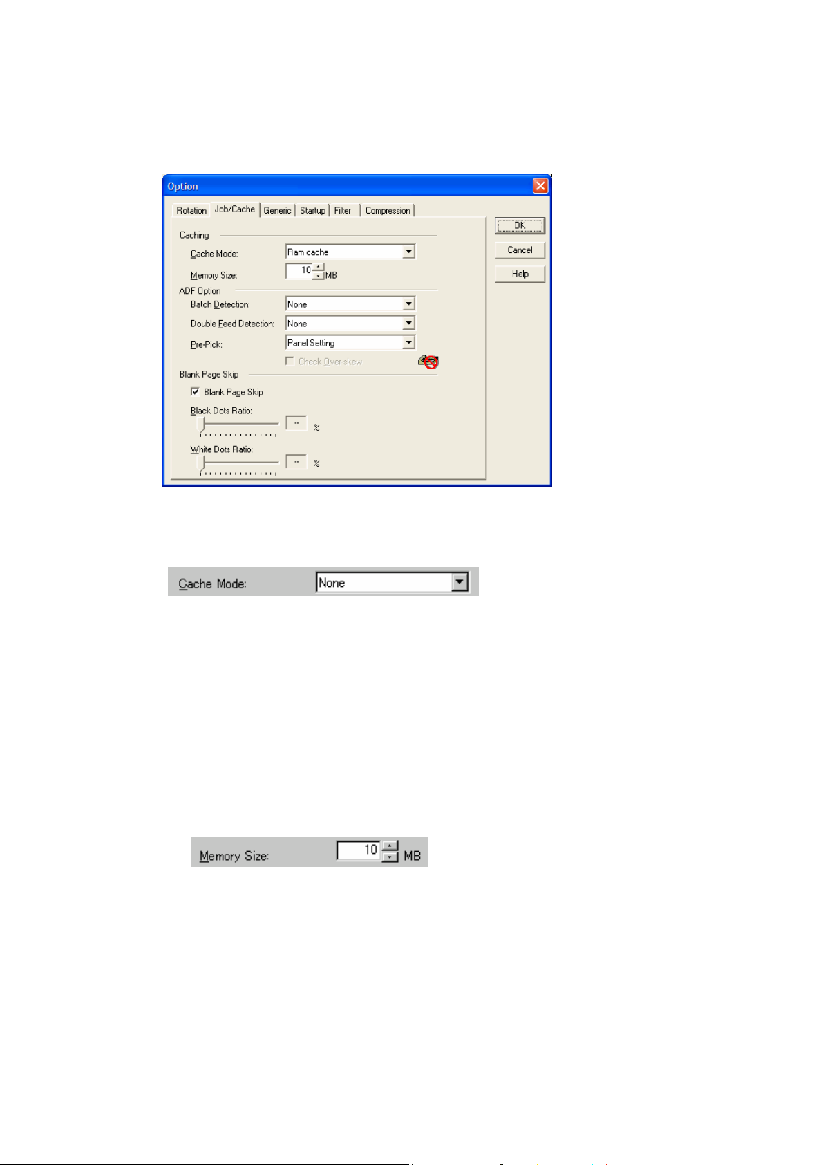
4.7.2 Job/Cache
Figure Option dialog (Job/Cache)
♦ Caching
Specifies whether to pre-read (cache) when a document is scanned. This option enables
faster scanning.
If processing of the application being used slows down and scanning stops, this option can
be used to prevent degradation of the scanning speed. (The effect, however, depends on the
environment being used.)
None
Caching is not performed.
Read ahead
One document page is scanned, and the data is pre-read and stored in PC memory
(main memory of the personal computer).
Ram cache
Prereads the allowable amount based on the allocated memory size and stores the data
in PC memory.
A memory size between 1 and 200 MB can be set.
Use Memory on Scanner
Pre-reads using the memory installed in the scanner (displayed only if supported by the
scanner).
34
Page 42

Use Both Memory
Pre-reads using memory of both Scanner and PC (displayed only if supported by the
scanner).
♦ Batch Detection
The application can detect documents on a specific type of form (special paper). The
application must support this function.
None
No detection. Scanning is done without change.
Include and Continue
After the special paper is detected, scanning continues. The data on the special paper is
also valid.
Include and Stop
After the special paper is detected, scanning stops. The data on the special paper is also
valid.
Exclude and Continue
After the special paper is detected, scanning continues. The data on the special paper is
excluded and will not be transferred to the application.
Exclude and Stop
After the special paper is detected, scanning stops. The data on the special paper is
excluded and will not be transferred to the application.
*Batch Detection can not be used with following Caching, “Use Memory on Scanner” or
“Use Both Memory”.
♦ Double Feed Detection
This option detects a double feed (occurs when two or more documents are sent) based on
the set condition.
If a double feed is detected when this setting has been turned on, the device will stop and an
error message output.
None
Double feed detection is not performed.
Hardware Setting
A double feed is detected based on the device setting.
Check thickness
The thickness of the transmitted document is checked by the sensor in the device.
A double feed is detected by detecting changes in the thickness when more than one
document is sent.
35
Page 43

Check length
The length of the transmitted document is checked by the sensor in the device.
A double feed is detected by detecting changes in the length when more than one
document is sent.
Check thickness and length
The thickness and length of the transmitted document are checked.
Check overlapping
The overlapping of the transmitted document is checked by the sensor in the device.
A double feed is detected by overlapping when more than one document is sent.
Check overlapping and length
The overlapping and length of the transmitted document are checked.
For example, the detection accuracy can be improved by using [Check thickness] or [Check
overlapping] for continuous scanning of forms that have different lengths and [Check
length] for scanning of forms that have different thicknesses.
Depending on scanner model, the selectable items are different. Refer to “Relevant Image
Scanner Specification” of Appendix.
♦ Pre-Pick
It specifies whether a document is picked and carried in front of the scanning position
before starting scanning operation at the ADF scanning.
Disable
Pre-Pick is not performed.
A document is picked and carried in front of the scanning position, after starting
scanning operation.
Enable
Pre-Pick is performed.
A document is picked and carried in front of the scanning position, before starting
scanning operation.
Panel setting
The setting of device is followed.
* When selecting “Enable,” you can scan faster than when selecting “Disable,” because of
Pre-Pick process.
When selecting “Enable,” if you cancel during the ADF scanning, a document remains in
the scanner in the Pre-Pick status.
36
Page 44
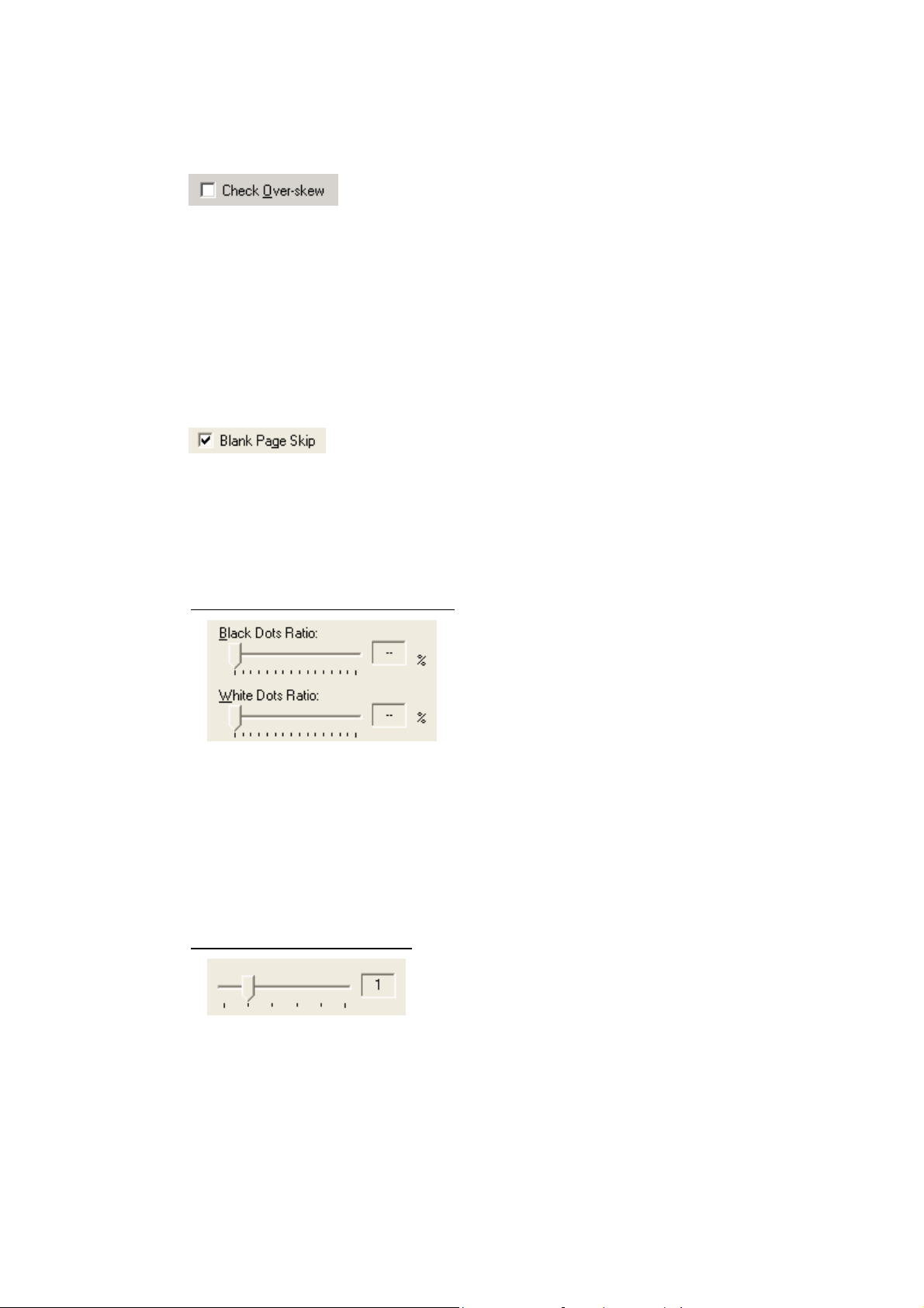
♦ Check Over-skew
The skew of the transmitted document is supervised during the ADF scanning.
When an over-skew is detected, the scanner is stopped and an error message is displayed.
* The image data of the skewed document is deleted.
* This functions, only when “Double Feed Detection” is enabled.
♦ Blank page skip
This option skips blank pages (blank pages or completely black pages) during ADF
continuous scanning.
Marking this check box, this function is enabled.
*This function can be used if “Ram cache” or “Use Both Memory
If an item other than “Ram cache” or “Use Both Memory
” has been selected in the
” is selected.
“Cache Mode:” and this check box is marked, it will change to “Ram cache”.
In case of Black&White or Helftone (In case of binary)
For blank pages, use the [White Dots Ratio] slider bar to set the skip condition. For
black pages, use the [Black Dots Ratio] scroll bar to set the skip condition.
The value displayed to the right of the scroll bar displays the garbage ratio(*1). If a
scanned document is below this value, it is recognized as a blank page. The setting range
is OFF(- -) and 0.2% to 3.0% (in increments of 0.2%).
*1: Ratio of black dots included in the scanning area (for blank pages)
In case of Color or Grayscale
Use the slider bar to set the skip condition in five stages from 1 to 5.
To make the blank pages easy to skip, increase the value of the setting.
37
Page 45

<If blank page skip does not operate properly>
− If a blank page is scanned, increase the value set.
− If scanning is skipped up to the required document, decrease the value set.
* When “Black Background” is selected in [Automatic Size and Skew detection], the
Blank page skip may not operate properly.
When Scanned image has many background noises, the Blank page skip may not
operate properly.
38
Page 46

4.7.3 Generic
Figure Option dialog (Generic)
♦ Unit/Scaling
This option selects the unit for the scanning area and preview window. One inch is
calculated as 25.4 millimeters. When inches are converted to millimeters, values are
rounded off.
Note.
The TWAIN specifications require that the data width be arranged in units of 32 bits.
As a result, a difference of up to 31 dots can be included, depending on the value set.
39
Page 47

4.7.4 Imprinter (Endorser)
Figure Option dialog (Imprinter)
♦ Enable Imprinter (Endorser)
Specifies enabling or disabling the imprinter function of the device.
When the option is selected, the scanned documents are imprinted according to the
instructions below. This applies only to the imprinter option. Therefore, the function is
supported only with the scanner which supports imprinter option(s). See "Relevant Image
Scanner Specification" described in the Appendix.
Disable
Imprinting is not performed.
Enable
Prints on documents using imprinter by the settings below.
In this case, it prints on the back side of documents after scanning.
Therefore, the printing is not included in a scanning result.
Depending on scanners, two imprinters can be installed and one of them can be selected to
use.
In this case, "
Pre-Imprinter (Printing before scanning, and on the front side of documents)
Enable" is displayed as follows.
Prints on documents using the imprinter installed in front part of the scanner.
In this case, it prints on the front side of documents before scanning.
Therefore, the printing can be included in a scanning result.
40
Page 48

Post-Imprinter (Printing after scanning, and on the back side of documents)
Prints on documents using the imprinter installed in rear part of the scanner.
In this case, it prints on the back side of documents after scanning.
Therefore, the printing is not included in a scanning result.
* [Pre-Imprinter] and [Post-Imprinter] cannot be used at the same time.
♦ Y Offset (Printing)
Specifies Y Offset from the edge of the original for the placement of printing. See
"Relevant Image Scanner Specification" in the Appendix because the standard value
specified here depends on the device.
♦ Direction (Printing)
Specifies the printing direction of endorsement strings. When printing from the head of
strings against to the direction of scanning, designate “Top to Bottom”. And when printing
from the tail of strings against to the direction of scanning, designate “Bottom to Top”
However, see the “Relevant Image Scanner Specification” described in the Appendix since
the available settings depend on the device.
♦ Font (Printing)
Specifies the printing orientation of characters.
Vertical : ABCD 0123
Horizontal :
Printing direction
Available settings vary depending on your scanner. Refer to “Relevant Image Scanner
Specification” in the Appendix.
♦ Bold
The imprinter string is outputted with bold font.
Available settings vary depending on your scanner. Refer to “Relevant Image Scanner
Specification” in the Appendix.
41
Page 49

♦ Initial Value (Counter)
Designates the initial count when the Imprinter String is set, including a counter value. See
the "Relevant Image Scanner Specification" described in the Appendix since the
programmable values range depends on the device.
♦ Counter Step (Counter)
Designates the counter increment of the set counter values. In other words, this value is
added to or subtracted from the counter each time one original is scanned.
An increment of 0, 1, or 2 may be specified. Usually, 1 is designated for a single-sided
original, and 2 for a double- sided original.
♦ Counter (Counter)
Designates whether to increase or decrease the specified step value.
♦ Imprinter String (Endorser)
Specifies the imprinter string.
The following characters can be outputted by the Imprinter.
Alphabet Letters : A-Z, a-z
Numeric Characters : 0, 1-9
Symbols : !”#$%&’()*+,-./:;<=>?@[\]^_`{|}~
Other : (Space)
(*The space is ignored when it is entered at the head of [String:].)
The following definitions can be used. They may also be selected from the menu, which is
displayed by clicking on "
%YYYY: The year is printed in four digits using the Western calendar.
%YYY: The year is printed using the two digits of the Japanese calendar (current, or
".
Heisei era).
%YY: The year is printed in the last two digits of the Western calendar.
%MMM: An English abbreviation of the month is printed; for example, JAN for January
and FEB for February.
42
Page 50

%MM: The month is printed in two digits; for example, 01 for January and 12 for
December.
%M: The month is printed using one or two digits; for example, 1 for January and 12
for December.
%DD: The day is printed using two digits; for example, 03 for the 3rd day of the month
and 26 for the 26th day of the month.
%D: The day is printed using one or two digits; for example, 3 for the 3rd day of the
month and 26 for the 26th day of the month.
%HH: The hour is printed using two digits of the 24-hour clock; for example, 08 for
8:00 a.m. and 14 for 2:00 p.m.
%H: The hour is printed using one or two digits of the 24-hour clock; for example, 8
for 8:00 a.m. and 14 for 2:00 p.m.
%NN: The minute is printed using two digits; for example, 02 for 8:02 a.m. and 48 for
2:48 p.m.
%N: The minute is printed using one or two digits; for example, 2 for 8:02 a.m. and 48
for 2:48 p.m.
%Nud: A counter value is printed by N digits which increases or decreases with each
page.
Programmable digits of the counter is 5 and 8 and described as "%05ud" and
"%08ud" respectively. (See the "Relevant Image Scanner Specification"
described in the Appendix since the programmable digits depend on the device.)
The initial counter and the methods of increasing and decreasing values can be
specified as explained above under the heading "Counter."
This specification is only permitted at the end of an Imprinter String (Endorser).
♦ Sample
Displays printed examples of the Imprinter String (Endorser) designated above.
Note.
The printed counter, date, and time do not always look like the sample because the scanning
option takes precedence.
43
Page 51

4.7.5 Start Up
Set up the Power Mode, Low-Speed Feeding and Scanner Operation Panel.
In some scanner models, displayed dialog box or setup item may be different or even
[Startup] dialog box may not be displayed.
In case of model fi-4110CU / fi-4110C(M3091DC) / fi-4210C(M3092DC)
In case of model fi-4120C / fi-4220C / fi-4530C
Figure Option dialog (Start Up)
44
Page 52

In case of model fi-5750C
Figure Option dialog (Start Up)
♦ Power Mode
Quick Start Mode
This mode keeps the lamp on regardless the scanner’s operating condition, which saves
times for lamp to become steady.
Low Power Mode
To save the power consumption, this mode turns the lamp off, if the scanner is not
operated for 14 minutes.
♦ Enable Low Speed Feeding
This is to specify to obtain a high quality image.
This function reduces times of start/stop during the scanning to obtain a smooth and high
quality image.
45
Page 53

♦ Prefer Scanning Speed
This mode makes scanning speed becomes faster in color/grayscale scanning.
When checking this check box, scanning speed becomes faster, but image quality is slightly
deteriorated.
Check this check box, when giving priority to scanning speed over image quality.
♦ Scanner Operation Panel
− Enable Scanner Panel
This is to specify whether the operator panel is enabled or not. If this is checked, button
operation on the operator panel becomes effective. (Note that the operator panel is
enabled only during the driver is activating.)
− Enable Scanner Dial
Specifies whether the value indicated by the density dial on the scanner is reflected on
scanning or not.
This setting is valid when both “Enable Scanner Panel” and this checkbox are checked.
With this density dial, the density can be set by five levels.
If moving the density dial to the UP direction, the density changes [Normal] >>[Darker
scanning]>>[Dark scanning]. If moving the density dial to the Down direction, the
density changes [Normal]>>[Lighter scanning]>>[Light scanning]. If the dial is in the
center, the scanning density is [Normal].
− Enable [Duplex] button
This specifies whether the [Duplex] button (to switch simplex and duplex) on the
scanner operator panel is enabled.
And, it distinguishes whether to scan from the ADF, or from the Flat Bed (FB), and
changes automatically.
If this box is checked,
when a document is on the ADF, scanning is started from the ADF.
And when no document is on the ADF, scanning is started from the FB.
Scanning changes [Simplex] >> [Duplex]>> [Simplex] each time the [Duplex] button
is pressed.
46
Page 54

− ADF/FB Automatic change
It distinguishes whether to scan from the ADF, or from the Flat Bed (FB), and changes
automatically.
When a document is on the ADF, scanning is started from the ADF.
And when no document is on the ADF, scanning is started from the FB.
− Enable [Send to] button
Specifies whether the preview is started by pressing the [Send to] button on the device.
− Enable FB Scanning Start
Specifies whether Scanning is started by closing the Flat bed cover.
When setting the document on the Flat bed and closing the Flat bed cover, scanning
starts.
− Enable Scanning Start
Specifies whether scanning is started by a scanner event.
◊ [Scan] button
Pressing the [Scan] button on the scanner starts scanning.
◊ ADF Document Detection
When a document is detected on the ADF, scanning automatically starts.
47
Page 55

4.7.6 Filter
Set the filter processing in this dialog.
The filter name is displayed in the list box.
While checking the checkbox in the left of the filter name, the filter processing is applied to
scanned image.
When selecting a filter name and clicking [Property] button, the setting dialog of the filter is
displayed.
Figure Option dialog (Filter)
The type of filter and the setting details are explained below.
48
Page 56

♦ Page Edge Filler
Eliminates the blemish around the paper edges by covering the area in (Black or White)
color.
Color
Select a color to paint over the image frame.
Can select "White" or "Black".
Please specify either white or black to match the background color of the document.
Filled Area
• [Unit]
Select a unit from “Inches”, “Millimeters”, and “Pixels”
• [Up], [Down], [Left], [Right]
Specify the paint area from each side of the scanned image in numbers.
[Up] : Input width from the top edge of the image.
[Down] : Input width from the bottom edge of the image.
[Left] : Input width from the left edge of the image.
[Right] : Input width from the right edge of the image.
Each value should be set in the following ranges.
0 < [Up] + [Down] < [Image Length]
0 < [Left] + [Right] < [Image Width]
If any values are out of these ranges, this function may not work.
49
Page 57

♦ Digital Endorser
Character string, such as the alphabet and number, is added on the data of the scanned image.
By using this filter, you can attach a name, a date, a time or a serial number on the scanned
images and manage them.
Printing
Specify the beginning position of the character string to output on the scanned image
data.
X Offset: Specify the position of the width direction from the left end of document.
Y Offset: Specify the position of the length direction from the top of document.
Unit: Select either “mm” or “inch” as the unit of offset value.
Counter
Specify the rule of the counter value used in the String.
Initial Value: Specify the initial count when the scanning starts.
Step: Specify the counter increment / decrement.
Counter: Select whether to increase or decrease the specified step value.
For example) In case of “Initial Value”= 0, “Step”= 2, “Counter”= Increment
0, 2, 4, 6, 8.....
String
Specify the output string.
The following characters can be outputted by the Imprinter.
Alphabet Letters : A-Z, a-z
Numeric Characters : 0, 1-9
50
Page 58

Symbols : !”#$%&’()*+,-./:;<=>?@[\]^_`{|}~
Other : (Space)
(*The space is ignored when it is entered at the head of [String:].)
The following definitions can be used. They may also be selected from the menu,
which is displayed by clicking on "
%YYYY: The year is printed in four digits using the Western calendar.
%YYY: The year is printed using the two digits of the Japanese calendar (current, or
Heisei era).
%YY: The year is printed in the last two digits of the Western calendar.
%MMM: An English abbreviation of the month is printed; for example, JAN for January
and FEB for February.
%MM: The month is printed in two digits; for example, 01 for January and 12 for
December.
%M: The month is printed using one or two digits; for example, 1 for January and 12
for December.
%DD: The day is printed using two digits; for example, 03 for the 3rd day of the month
and 26 for the 26th day of the month.
%D: The day is printed using one or two digits; for example, 3 for the 3rd day of the
month and 26 for the 26th day of the month.
%HH: The hour is printed using two digits of the 24-hour clock; for example, 08 for
8:00 a.m. and 14 for 2:00 p.m.
%H: The hour is printed using one or two digits of the 24-hour clock; for example, 8
for 8:00 a.m. and 14 for 2:00 p.m.
%NN: The minute is printed using two digits; for example, 02 for 8:02 a.m. and 48 for
2:48 p.m.
".
%N: The minute is printed using one or two digits; for example, 2 for 8:02 a.m. and 48
for 2:48 p.m.
%Nud: A counter value is printed by N digits which increases or decreases with each
page.
Programmable digits of the counter is 5 and 8 and described as "%05ud" and
"%08ud" respectively. (See the "Relevant Image Scanner Specification"
described in the Appendix since the programmable digits depend on the device.)
The initial counter and the methods of increasing and decreasing values can be
specified as explained above under the heading "Counter."
This specification is only permitted at the end of an Imprinter String (Endorser).
Sample
Displays the output examples of the String specified above.
Note.
The counter, date, and time do not always look like the sample because this string is output
during scanning.
51
Page 59

4.7.7 Compression
Click this tab and mark the check box to enable or disable JPEG compression for data
transfer from the image scanner. (This function is available only for Color or Grayscale
scans.)
Figure Option dialog (Compression)
♦ Imprinter String (Endorser)
Converts scanned image data into JPEG format for transfer. Because of smaller data size,
data transfer time is shorter than that of ordinary method (when the check box is not
marked).
♦ Jpeg Quality
Specifies data compression rate for JPEG transfer. Increase the value when you prefer to
get finer image quality, otherwise decrease the value for smaller data size.
Note.
・ Image quality may deteriorate due to scanning with JPEG compression.
・ When JPEG compression is enabled, lengths and widths of images may slightly be
different from that of the scans without JPEG compression.
・ This function may not be available for some image scanner models.
52
Page 60

4.8 Setting Advance Options
The "advance dialog" is used to set items related to image processing. The settings apply to
device-specific functions and items that differ according to whether the scanner used supports
them.
The advance option specification is divided into "Color Variance", "Image Processing", and
"Auto Binary".
The supported options depend on the scanner. See "Relevant Image Scanner Specification" in
the Appendix. (
is displayed for options that cannot be used.)
The option dialog for this driver is explained below.
The commonly used buttons are explained first.
♦ [Default]
Makes the new setting valid and closes the option dialog box.
♦ [OK]
Makes the new setting valid and closes the option dialog box.
♦ [Cancel]
Makes the new setting invalid, returns the setting to the previous value, and terminates
processing.
♦ [Help]
Displays online help.
53
Page 61

The options are described below:
4.8.1 Gray
Figure Advance dialog (Gray)
♦ Gamma Pattern
This option corrects distortions from nonlinear image representation. Scanner sensors are
generally designed to generate output linear to the density of the light reflected from the
document. However, most output terminals do not produce output that has the desired
linear relation to the input, and the resulting distortion must be corrected.
One of the following can be selected as a correction pattern: "Normal", "Soft", "Sharp",
"Download Pattern", or "Custom".
Some scanner models do not support this function. See "Relevant Image Scanner
Specification" in Appendix.
When "Download Pattern" is selected, the above dialog box opens.
54
Page 62

Select the gamma pattern download file to be used from the list of file names. Then, press
the [OK] button. Correction will then be executed using the selected gamma pattern.
If the gamma pattern download file has not been registered in the list of file names, use the
[Add] button to register the file.
See "Download Pattern File" for information about how to specify the file.
When "Custom" is selected, a custom specification can be entered.
Entering an arbitrary value between 0.1 and 10.0 enables a gamma pattern corresponding to
the entered value to be specified.
♦ White Level Follower
Select this option to scan a document whose background color is not white, such as a
newspaper.
Select "Auto", "Enable", or "Disable".
When "Enable" is selected, the document is scanned using background follow-up (for line
drawings). When "Disable" is selected, the document is scanned using the standard basic
white background (for photographs). When "Auto" is selected, the option automatically
switches to the optimal setting based on the specified "Image Mode".
"White Level Follower" is used to adjust the density of the white background of a
document and correct variations in the background color by compensating the pixels of
scanned images individually.
For ordinary use, set "White Level Follower" to off. Use of "White Level Follower" often
increases the background noise because IPC-3/3D is very sensitive.
This option is not available if "Gray Scale" is selected for "Image Mode".
In addition, some scanner models do not support this option. See "Relevant Image Scanner
Specification" in the Appendix.
♦ Dropout Color
This option enables scanning excluding the selected color information of green, red, or blue
(the three primary colors of light). For example, to scan black characters framed in red,
selecting red for scanning will scan only the black characters.
Some scanner models do not support this function. See "Relevant Image Scanner
Specification" in Appendix.
55
Page 63

♦ Reverse
This option specifies whether to reverse the black and white of a scanned image.
If this option is selected, black and white are reversed by reversing the black and white
pixels. If this option is not selected, the black and white values of the reproduced image
correspond to the original image.
Some applications do not permit normal operation. If this occurs, contact the manufacturer
of the application.
56
Page 64
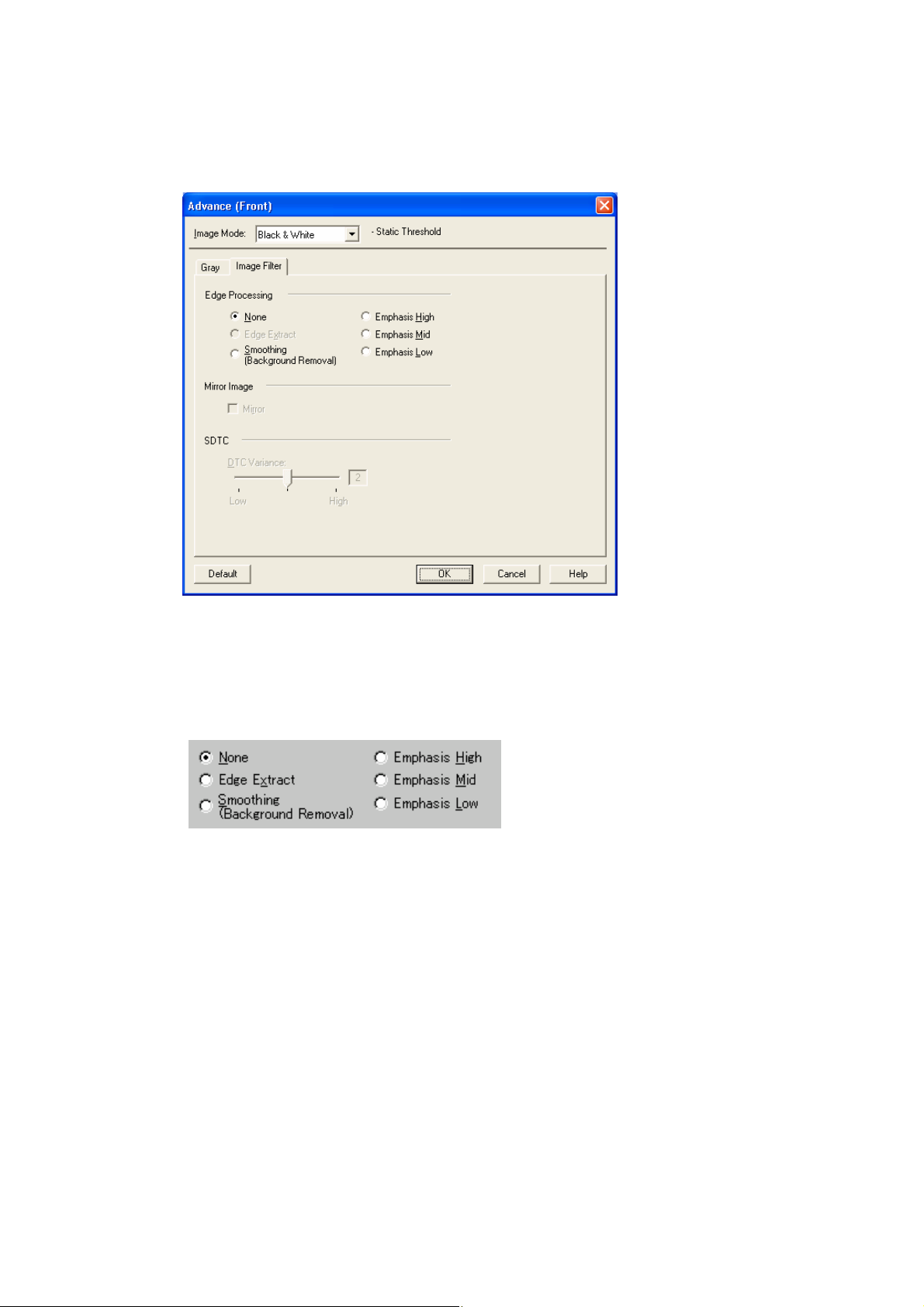
4.8.2 Image Filter
Figure Advance dialog (Image Filter)
♦ Edge Processing
This option specifies the sharpness of a scanned image.
Select "None", "Edge Extract", or "Smoothing (Background Removal)".
None
Edge processing is not performed.
Edge Extract
This option outputs an image with the edge extracted.
If this option is selected, the boundary between the black part and white part in a closed
area is traced and the edge extracted.
"DTC Variance" and "Edge Extract" are mutually exclusive.
Smoothing (Background Removal)
This option specifies whether to smooth the curves in an image by removing zigzag
lines. "Smoothing" or "Emphasis" can be selected. In addition, "Edge Extract" and
"Emphasis" are mutually exclusive.
57
Page 65

Emphasis
This option outputs an image with the edge emphasized.
"Emphasis High", "Emphasis Mid", or "Emphasis Low" can be selected.
If "Emphasis High" is selected, the image becomes sharper. If "Emphasis Low" is
selected, the image appears less distinct.
♦ Mirror
This option specifies whether to flip the scanned image over the scanning axis.
If this option is selected, a mirror image of the original image is obtained.
♦ Variance (DTC Variance)
This option specifies the value for adjusting the dynamic threshold of an image based on
the brightness of the image.
A value is specified using the slider. The smaller the value, the lower the variance becomes.
The higher the value, the higher the variance becomes. To specify the value, drag the tab of
the slider to the desired setting position. The current setting is displayed on the right. This
option is mainly used for optical character recognition (OCR). It enables dark and bright
images in a document to be scanned effectively.
♦ Floating Slice Level (SDTC)
Specifies the level of the binary processing done by the floating slice.
Set the level to higher when scanning documents with dark colored background.
* This is displayed only when the SDTC mode (Floating Slice) is specified.
58
Page 66

4.8.3 DTC
This option is valid only when "DTC Variance" is set.
Figure Advance dialog (DTC Mode)
♦ Scan mode
This option selects one of the following two scan modes:
[for OCR]: This mode is for text recognition applications where irregularity in the image
is undesirable.
[for Image]: This mode is for image scanning applications that scan images without prior
smoothing.
The specification changes the specifiable items and members for "Threshold Curve" and
"Gamma Curve".
The selection screens for "for OCR" and "for Image" are not displayed if IPC-3/3D and
IPC-4D are installed.
59
Page 67

♦ Threshold Curve
This option specifies the relationship between the threshold value and the maximum density.
The specification method depends on the [Scan mode] setting.
In [for OCR] mode, use the scroll bar to set the inclination and density level between 0 and
5. Click the arrow of the scroll bar or drag the scroll marker to the desired setting position.
The current setting is displayed in the center (figure on the left).
In [for Image] mode, select [Normal] or [Light] (figure on the right).
If IPC-3/3D and IPC-4D have been installed, there is no difference between [for OCR] and
[for Image]. The scroll bar is used to set the inclination and density level between 0 and 7.
(The figure on the right is not displayed.)
♦ Gamma Curve
This option specifies the gamma correction curve pattern.
The available choices depend on the [Scan mode] setting.
In [for OCR] mode, select [OCR1] or [OCR2].
In [for Image] mode, select [Dark Image] or [Even].
For IPC-3/3D and IPC-4D, the gamma curve need not be specified because the contrast is
adjusted automatically. ([Gamma Curve] is not displayed.)
♦ Equal to White
At conversion to binary, this option specifies whether to set the data to black or white when
the threshold value and the value of the scanned data are equal.
This option is not available for IPC-4D.
♦ Ball-Point Pen Mode
When an image made with a pencil or ball-point pen is scanned, the light reflected from the
pencil lead or ink is not uniform. As a result, part of the image may be missing. If the
[Ball-Point Pen] checkbox is checked, filtering is applied to offset the bright area in the
document and compensate for disconnected or faint lines.
60
Page 68

♦ OCR Smoothing/ Background Removal
The OCR smoothing is the function to make smooth the notched part of line-drawing, and
the Background Removal is the function to remove the uneven background.
These functions are enabled when it is selected.
For further information, please refer to the User’s guide attached to the IPC board since the
function to be operated is different by the type of IPC.
At IPC-3/3D, [Noise Removal] and [OCR smoothing/ Background removal] is enabled
exclusively.
♦ Noise Removal
This option automatically removes spots that appear as black stains in a white area and
spots that appear as white stains in a black area.
This option uses an algorithm that removes particles from 2 x 2 to 5 x 5 dot matrixes. The
size of one dot depends on the resolution setting, and is equivalent to 1/400 inch for 400 dpi.
Particles are distinguished from the text by whether they are connected to other dots within
the specified number of pixels.
At IPC-3/3D, [Noise Removal] and [OCR smoothing/ Background removal] is enabled
exclusively.
Figure Advance dialog (DTC Mode) <IPC-3/3D and IPC-4D installed>
61
Page 69

4.8.4 When Color (/Grayscale) is specified
For color scanners, when “Color” is selected in the [Image Mode], the [Advance] dialog
changes as follows. And in case of some color scanners, when selecting “Grayscale” the
[Advance] dialog change as same as selecting “Color”.
There are two image samples which are “Sample (before processing)” and “After (after
processing)” on this dialog. When you change a setting item, the effect of the setting item is
reflected in the image “After”.
You can specify the items, checking their effect.
<Image Mode : Color selected> <Image Mode : Grayscale selected>
Figure Advance dialog (Color / Grayscale)
♦ Shadow/Highlight (Color / Grayscale)
Shadow : The highlight allows the darkest part of the document to be controlled.
The higher the shadow value, the darker the image.
Highlight : The highlight allows the brightest part of the document to be controlled.
The higher the highlight value, the lighter the image.
Any levels on the document outside these settings are flooded (all 0 or 255), while the
interval between the shadow and highlight settings are equally divided into 255 levels,
which are used to create the output images. This means that if the shadow and highlight
settings are close to each other, the contrast for that interval in the scanned document will
be very strong (but with all other areas maximizing high or low).
62
Page 70

♦ Contrast/Brightness (Color / Grayscale)
Contrast : Sets the contrast of light and shadow in a scanned image. Specify the
contrast with a number in the range of 1 (low [soft]) to 255 (high [sharp]).
If this value is increased, the dark part of the image is shown darker and the
light part is shown lighter.
Some scanner models do not support this function. See "Relevant Image
Scanner Specification" in Appendix.
Brightness : Sets the brightness of the overall image. Specify the brightness with a
number in the range of 1 (light) to 255 (dark). To darken the overall image,
increase the value of the setting. To brighten the overall image, decrease the
value.
♦ Gamma (Color / Grayscale)
This option corrects distortions from nonlinear image representation. Scanner sensors are
generally designed to generate output linear to the density of the light reflected from the
document. However, most output terminals do not produce output that has the desired
linear relation to the input, and the resulting distortion must be corrected.
An arbitrary range is between 0.1 and 10.0.
♦ Preset Gamma (Grayscale only)
This option corrects distortions from nonlinear image representation. Scanner sensors are
generally designed to generate output linear to the density of the light reflected from the
document. However, most output terminals do not produce output that has the desired
linear relation to the input, and the resulting distortion must be corrected.
One of the following can be selected as a correction pattern: "Normal", "Soft", "Sharp",
"Download Pattern", or "Custom".
Some scanner models do not support this function. See "Relevant Image Scanner
Specification" in Appendix.
63
Page 71

When "Download Pattern" is selected, the above dialog box opens.
Select the gamma pattern download file to be used from the list of file names. Then, press
the [OK] button. Correction will then be executed using the selected gamma pattern.
If the gamma pattern download file has not been registered in the list of file names, use the
[Add] button to register the file.
See "Download Pattern File" for information about how to specify the file.
When "Custom" is selected, you can specify the values on the [Shadow/Highlight],
[Contrast/Brightness] and [Gamma] tab.
♦ Color select (Color only)
It is possible to select independent value on each color
♦ sRGB Output (Color / Grayscale)
Scans images by using the color control information of “Color Space Profile.icm” (the
standard color profile of Windows).
* Refer to “Windows Help” to learn more about “color profile”.
64
Page 72
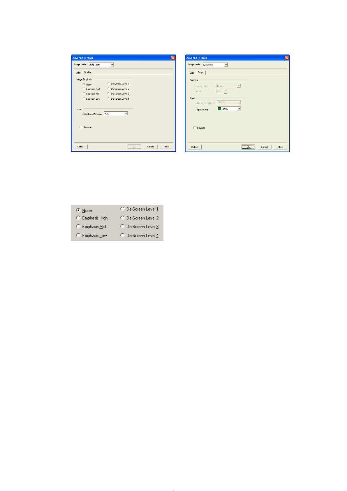
<Image Mode : Color selected> <Image Mode : Grayscale selected>
Figure Advance dialog ([Quality] / [Gray] tab)
♦ Image Emphasis (Color only)
This option specifies the sharpness of a scanned image.
Select "None", "De-Screen" or "Emphasis".
None
Edge processing is not performed.
Emphasis
This option outputs an image with the edge emphasized.
"Emphasis High", "Emphasis Mid", or "Emphasis Low" can be selected.
If "Emphasis High" is selected, the image becomes sharper. If "Emphasis Low" is
selected, the image appears less distinct.
De-Screen
"De-Screen Level 1", "De-Screen Level 2", "De-Screen Level 3", or "De-Screen Level
4" can be selected.
This option eliminates moirés patterns. To eliminate more effectively, higher level is
selected.
65
Page 73

♦ White Level Follower (Color)
Select this option to scan a document whose background color is not white, such as a
newspaper.
Select "Auto", "Enable", or "Disable".
When "Enable" is selected, the document is scanned using background follow-up (for line
drawings). When "Disable" is selected, the document is scanned using the standard basic
white background (for photographs). When "Auto" is selected, the option automatically
switches to the optimal setting based on the specified "Image Mode".
"White Level Follower" is used to adjust the density of the white background of a
document and correct variations in the background color by compensating the pixels of
scanned images individually.
Some scanner models do not support this function. Refer to "Relevant Image Scanner
Specification" in Appendix.
♦ Reverse (Color / Grayscale)
This option specifies whether to reverse the black and white of a scanned image.
If this option is selected, color data is reversed. If this option is not selected, the color
values of the reproduced image correspond to the original image.
Some applications do not permit normal operation. If this occurs, contact the manufacturer
of the application.
Some scanner models do not support this function. Refer to "Relevant Image Scanner
Specification" in Appendix.
♦ Dropout Color (Grayscale only)
This option enables scanning excluding the selected color information of green, red, or blue
(the three primary colors of light). For example, to scan black characters framed in red,
selecting red for scanning will scan only the black characters.
Some scanner models do not support this function. Refer to "Relevant Image Scanner
Specification" in Appendix.
66
Page 74

4.9 Setting the Setting Manager Options
These options are used to manage the setting files, and switch the basic scan dialog display.
Press the [Config...] button of the main dialog to open the [Configuration] dialog box shown
below.
Figure Configration dialog box
♦ Setting Files
The setting information of the scan conditions can be saved in a “Setting file.”
Scan condition settings that have been set in advance in this dialog can be selected from the
list of setting files. This enables selection of all settings at the same time without having to
enter the scan conditions one at a time. Press the
button to open the list of setting files.
Subsequent scanning operations can be performed effectively by registering several types
of scan conditions that are frequently used.
67
Page 75

♦ FTS File Information
The information of the setting file selected in [Setting Files] is displayed.
♦ [Show this dialog next open] checkbox
If this checkbox is checked, [Basic Scan Dialog] will be activated the next time the driver is
activated.
♦ [OK] button
Makes the new setting valid, closes this dialog box, and returns to the main dialog.
♦ [Add] button
Adds the setting of the current driver to a setting file.
Pressing the [Add] button opens the [File addition] dialog.
Enter the [Description] and [Filename] as shown in the example above. Then, press the
[OK] button to add the new setting file. To cancel, press the [Cancel] button.
Description: Enter a character string to be displayed in the selection frame of the
[Setting Files].
Filename: Specify the name of the file used to save the settings.
68
Page 76
♦ [Delete] button
Deletes unnecessary setting files.
Select the setting file to be deleted and then press the [Delete] button. A confirmation
dialog will be displayed. Press the [OK] button to delete the setting file. To cancel, press
the [Cancel] button.
♦ [Help] button
Displays online help.
♦ [Initialize] button
All of scan settings are returned to the initial value.
69
Page 77

4.10 Basic Scan Dialog
The basic scan dialog contains only the minimum functions required for scanning. The detailed
setting functions of the main dialog have been omitted.
Scanning can be easily performed by selecting a registered setting file.
The basic scan dialog is also useful for avoiding incorrect operations when standard work is
performed.
By checking the [Show this dialog next open] checkbox of the [Configuration] dialog, the Basic
Scan dialog will be opened instead of the main dialog box at the next activation.
<Scan Procedure>
1. Select the file to be used from the list of setting files.
2. Click the [Scan] button.
Scanning is performed based on the settings of the setting file information.
<Configuration>
♦ Setting Files
A list of setting files is displayed. When the desired file is selected, the setting information
saved in the file will be read and reflected during scanning.
70
Page 78

♦ FTS File Information
The contents of the selected file are displayed.
♦ [Scan] button
Executes scanning based on the contents of the setting file.
♦ [OK] button
Terminates without performing the scan operation.
♦ [Adjust] button
Switches from the basic scan dialog to the main dialog.
♦ [Help] button
Displays online help.
♦ [Show this dialog next open] checkbox
If this checkbox is checked, the [Basic Scan Dialog] will be opened at the next startup. If
this checkbox is not checked, the main dialog will be opened at the next startup.
71
Page 79

4.11 Download Pattern File
The "download pattern file" of this driver is a file that defines the patterns to be used by the
scanner to execute various image processing. This file is available in the following two versions.
Each version can be selected using the [Download Selection Dialog] that opens when
[Download] is selected.
The file is a text file that conforms to the following rules. Use an appropriate text editing
program (for example, "Note Pad" in the operating system) to edit the file.
♦ Dithered download pattern file
Any user defined dithered pattern can be used to scan an image by downloading the pattern
from the dithered download file to the scanner. The defined pattern becomes effective
when [Download Pattern] is selected for [Halftone].
Some models do not support this file. See "Relevant Image Scanner Specification" in
Appendix.
Although the standard extension of the file name is ".DTH," there may be exceptions.
Coding configuration:
(n, size in the X direction),(m, size in the Y direction),
(pattern value for the X1/Y1 coordinates),
(pattern value for the X1/Y2 coordinates),
(pattern value for the X1/Y2 coordinates),........
(pattern value for the Xn/Ym-2 coordinates),
(pattern value for the Xn/Ym-1 coordinates),
(pattern value for the Xn/Ym coordinates)
Meaning of each element:
(n, size in the X direction) indicates the size of the matrix in the X direction. Specify 8
for the scanner supported by this driver.
(m, size in the Y direction) indicates the size of the matrix in the Y direction. Specify 8
for the scanner supported by this driver.
1
1
(Pattern value for the Xx/Yy coordinates) contains a values in the range of 0 (bright) to
255 (dark) that specifies the brightness of the X coordinate, x, and the Y coordinate, y.
Note
Use a delimiter other than a number to delimit elements. For most cases, use a comma (,).
1
In case of fi-5750C, you can specify the value from 1 to 32.
72
Page 80

Example: In case of 8x8 matrix
8, 8,
128, 128, 128, 128, 128, 128, 128, 128,
255, 128, 128, 128, 128, 128, 128, 128,
255, 255, 128, 128, 128, 128, 128, 128,
255, 255, 255, 128, 128, 128, 128, 128,
255, 255, 255, 255, 128, 128, 128, 128,
255, 255, 255, 255, 255, 128, 128, 128,
255, 255, 255, 255, 255, 255, 128, 128,
255, 255, 255, 255, 255, 255, 255, 128,
8 elements
8 elements
73
Page 81

♦ Gamma download pattern file
Any user defined gamma correction processing can be performed by downloading the
pattern from the gamma download file to the scanner. The defined pattern becomes
effective when [Download Pattern] is selected for [Gamma Pattern].
Some models do not support this file. See "Relevant Image Scanner Specification" in
Appendix.
Although the standard extension of the file name is ".GMA," there may be exceptions
Creation of a gamma download pattern file can be facilitated using the following utilities
for editing the gamma correction pattern:
Coding configuration:
(gray-scale in the X direction),(gray-scale in the Y direction),
(X0 output value),(X1 output value),(X2 output value),........
(X253 output value),(X254 output value),(X255 output value)
Meaning of each element:
(gray-scale in the X direction) indicates the size and the gray scale of the input value.
(In this driver, this value is fixed at 256.)
(gray-scale in the Y direction) indicates the size and the gray scale of the output value.
(In this driver, this value is fixed at 256.)
(Xx output value) indicates the output value, in the range of 0 (bright) to 255 (dark), for
an input value x.
Note
Use a delimiter other than a number to delimit elements. For most cases, use a comma (,).
74
Page 82

Example
256, 256,
255, 254, 253, 252, 251, 250, 249, 248, 247, 246, 245, 244, 243,
242, 241, 240, 239, 238, 237, 236, 235, 234, 233, 232, 231, 230,
229, 228, 227, 226, 225, 224, 223, 222, 221, 220, 219, 218, 217,
216, 215, 214, 213, 212, 211, 210, 209, 208, 207, 206, 205, 204,
203, 202, 201, 200, 199, 198, 197, 196, 195, 194, 193, 192, 191,
190, 189, 188, 187, 186, 185, 184, 183, 182, 181, 180, 179, 178,
177, 176, 175, 174, 173, 172, 171, 170, 169, 168, 167, 166, 165,
164, 163, 162, 161, 160, 159, 158, 157, 156, 155, 154, 153, 152,
151, 150, 149, 148, 147, 146, 145, 144, 143, 142, 141, 140, 139,
138, 137, 136, 135, 134, 133, 132, 131, 130, 129, 128, 127, 126,
125, 124, 123, 122, 121, 120, 119, 118, 117, 116, 115, 114, 113,
112, 111, 110, 109, 108, 107, 106, 105, 104, 103, 102, 101, 100,
99, 98, 97, 96, 95, 94, 93, 92, 91, 90, 89, 88, 87, 86, 85, 84,
83, 82, 81, 80, 79, 78, 77, 76, 75, 74, 73, 72, 71, 70, 69, 68,
67, 66, 65, 64, 63, 62, 61, 60, 59, 58, 57, 56, 55, 54, 53, 52,
51, 50, 49, 48, 47, 46, 45, 44, 43, 42, 41, 40, 39, 38, 37, 36,
35, 34, 33, 32, 31, 30, 29, 28, 27, 26, 25, 24, 23, 22, 21, 20,
19, 18, 17, 16, 15, 14, 13, 12, 11, 10, 9, 8, 7, 6, 5, 4, 3, 2, 1, 0
75
Page 83

5. Using the Gamma Pattern Editor
5.1 Start-up
Click on [Start] and select [Download Pattern Editor] from "Scanner Utility for Microsoft
Windows" under [Programs]. The following menu is displayed:
Figure Gamma Pattern Editor Tool start-up menu
76
Page 84

5.2 [File] menu
♦ [Load...]
This menu is used to read the Gamma Download file and display the graph and gradations.
The name of the open file is displayed above the graph area.
♦ [Save]
The gamma pattern currently being edited is saved in the file whose name is displayed
above the graph area. If no filename is displayed, the pattern is named and saved in that
file.
♦ [Save As...]
The gamma pattern currently being edited is named and saved in that file. The saved
filename is then displayed above the graph area.
♦ [Close]
Select this to exit the editing program.
5.3 [Help] menu
♦ [About]
Information related to this editor and its version number is displayed.
77
Page 85

5.4 Gamma Pattern Editing
♦ Graph Area
The graph area is a 256-dot x 256-dot white square area bordered by black lines, where the
relationship between the input values of 0 to 255 (x axis) and output values of 0 to 255 (y
axis) is indicated in blue lines. Each graph dot represents one division (unit).
♦ Gradation
The input is displayed in black and white in 256 single-dot steps from 0 at the left border to
255 at the right border. The gamma function of the scanner is displayed. After saving it,
the displayed (gray scale) gamma function is fixed and constant. The output values are
displayed in single dots in relation to the input values and the brightness of the output
equipment is displayed. To ensure accurate display, the display must be set for "TrueColor" or greater.
♦ Gamma
Calculation of the output values is based on the value γ entered in the edit box; the graph
and the gradation are then displayed. The values that can be input are integers greater than
0 or fractions.
<<Formula>> Output = (input ÷ 255)
γ
x 255 (Input = 0 - 255)
♦ Free Edit
Designates whether to enable editing of the graph area directly using the mouse cursor.
If this box is checked, the gamma pattern input edit box cannot be used and only editing
using the mouse cursor is supported.
♦ Smooth
Designates whether to smooth edited curves. This setting is only valid when Free Edit is
selected. In this setting, the curved lines drawn by the mouse are automatically smoothed.
This is reflected in the graph and gradation display.
♦ Reverse
Designates whether to reverse black and white. When this box is checked, the current
output values are converted to (255 - output values).
78
Page 86

6. Definition of Scanner and Camera Properties
6.1 Displaying Scanner and Camera Properties
Double-click the [Scanner and Camera] icon on the [Control Panel] to display the
corresponding properties dialog box shown below.
If the scanner driver has been properly installed, the icon of your scanner is displayed. Select
the model name. And double-click the icon or select the [Properties...] by using right-click.
The Properties dialog box shown below is displayed.
In this dialog box, the scanner can be checked and information related to different kinds of
related devices can be confirmed. An explanation of each tab folder and its use is below.
*Depending on scanners, [Events] and [Device Set] tab may not be displayed.
6.2 General Tab
General information on the driver for a connected scanner can be displayed, and the connection
can be tested from this folder.
79
Page 87

6.3 Events Tab
On the Events tab, an application can be specified to be started automatically by “Scanner
events” such as “pushing buttons on the scanner” or “placing documents to the scanner”.
(The Events tab is not displayed if the device does not support this function.)
♦ Scanner events
Select a “scanner event” from the list box to start an application. Please select the item to
set up from the following events.
"Auto check of paper supply": When placing paper to the ADF.
"Start button" or "Scan button": When pushing the "Start" or the "Scan" button of the
scanner.
"Send to1-9": When pushing the "SendTo" button of the scanner.
(“Scanner events” may not be displayed depending on scanners.)
♦ Send to this application
Mark on the check box of an application to be started by the operation specified in the
above [Scanner events]. Multiple applications can be specified. When two or more
applications are specified, a dialog box appears to select one to be started by the operation.
♦ Disable device events
If these functions are not used, mark on this check box.
* If the above settings are not activated by clicking [OK] or [Apply], please reboot the PC.
80
Page 88

In Windows XP, the following “Events” screen may be displayed.
(*This screen has the same function as the above screen.)
♦ Select an event
Select a “scanner event” from the list box to start an application. Please select the item to
set up from the following events.
" Feeder loaded with paper ": When placing paper to the ADF.
"Start button" or "Scan button": When pushing the "Start" or the "Scan" button on the
scanner.
"Send to1-9": When pushing the "SendTo" button of the scanner.
♦ Actions
Select an action when the event selected [Select an event] occurs.
- Start this program:
The application selected from the right list box starts when the event occurs.
- Prompt for which program to run
The window for selecting application appears when the event occurs.
- Take no action
Nothing starts even if the event occurs.
81
Page 89

6.4 Diagnostic Tab
To perform more detailed diagnostic tests than those provided in the general tab folder, click
the [Diagnose] button.
In Windows
tests.
®
2000 or Windows®XP, only a user who has administrator authority can run these
82
Page 90

6.5 Device Information Tab
A list of the functions compatible with the selected scanner driver is displayed. The items
displayed depend on the selected model of scanner. Only hardware functions are displayed.
The functions realized by software are not displayed in this tab folder. Therefore, the displayed
content may not match the content specified during reading. The contents of this tab folder are
not displayed if the scanner driver is either currently in use or not connected to the computer. If
they are not displayed, stop the application being used by the scanner driver or check the
connection. Then, select this tab folder again to display the contents.
83
Page 91

6.6 Device Setup Tab
Information related to the operation and maintenance of the scanner driver can be displayed and
set up. For some scanner models, this tab may not be displayed, or some items cannot be set up
(grayed out). Changing the setup activates the Apply button. The changed setup is reflected on
the device only if the Apply button or OK button is clicked. The contents of this tab folder are
not displayed if the scanner driver is either currently in use or not connected to the computer. If
they are not displayed, stop the application being used by the scanner driver or check the
connection. Then, select this tab folder again to display the data.
®
In Windows
setup from this tab folder.
2000 or Windows®XP, only a user who has administrator authority can change the
♦ Page counter
An approximate total of the numbers of pages that the ADF and flat bed (FB) have scanned
are displayed. An equivalent count of the pages scanned after consumables are replaced is
also displayed. To set the consumables counter to zero after replacing consumables, click
the [Clear] button. Depending on the device, this operation can be executed using the
operation panel of the device. Displayed consumables names or item numbers also vary
depending on the device. For information, see the operator’s guide of the device.
Note
Depend on some scanner models, once the [Device Set] tab appears, the operation panel
is unable to be handled. In this case, close this dialog and turn the power ON/OFF of the
scanner. After the scanner setup, the operation panel is able to be handled.
84
Page 92

When using a scanner, the following message may be displayed.
If this message appears, replace consumables following the instructions below.
< If replacing consumables immediately >
1. Check [This message not display again.]
2.
In cases where consumables are replaced after completing all documents being scanned,
click [Ignore]. In cases where scanning is stopped for an immediate replacement, click
[Cancel].
Following the operator’s guide of the device, replace the consumables.
3.
4.
Select [Page counter] from [Device setup], click [Clear] button to reset the
consumables counter.
< If replacing later (immediate replacement is impossible) >
1. If it is not necessary to display this message again, check [This message not display
again]*. If it is necessary to display this message again after scanning xxx pages, check
[Warns again after scanning xxx pages].
If the scanning is continued, click [Ignore] and close the message. If the scanning is
2.
stopped, click [Cancel] and close the message.
Replace consumables as soon as possible or when this message appears next time.
3.
After the replacement, click [Clear] of [Device Setup] under [Page Counter] to reset the
4.
consumables counter.
(* If [This message not display again] is checked, this message will not appear before the
consumables counter is reset.)
Power saving:
Specify when the lamp turns off. This is the elapsed time after a scan is complete.
85
Page 93

[Power saving mode] button
This specifies the power saving mode.
If this button is clicked, the following dialog box is displayed.
Quick Start Mode
This mode keeps the lamp on regardless the scanner’s operating condition, which
saves times for lamp to become steady.
Low Power Mode
To save the power consumption, this mode turns the lamp off, if the scanner is not
operated for 14minutes.
* This button may not be displayed for some scanner models.
[Offset] button
When this button is clicked, the following dialog box is displayed.
Using this dialog box, the offset of the leading edge and magnification for the sub-scanning
direction can be changed.
Offset Setting:
If the position of the scanned image shifts from the original document, fine adjustment
is possible.
86
Page 94

At shipment, the offset has been adjusted to an optimum value within a certain range.
Therefore, adjustment is not generally required.
*The maximum size of changes depends on the device.
Enable eliminating a dark area on the top of the image.
Enable eliminating a dark area on the left side of the image.
These modes can be selected to eliminate the dark area on the leading edge and the left
side appeared when using the flat bed
*These functions may not be displayed for some scanner models.
Vertical magnification Adjustment
The Vertical magnification correction value of sub-scanning direction can be changed.
For ADF scanning, the image is expanded or shrunk in the paper feeding direction
based on the setting value at shipment.
For FB scanning, the image is expanded or shrunk in the direction to which the scan
head moves based on the setting value at shipment.
This function is used to adjust the image whose ratio of length and width seems
different from the original document.
*The settable value varies depending upon the device used.
[OK] button
The adjusted value is written to the EEPROM.
* This button may not be displayed depending on the scanner model.
The available settings also vary depending on the scanner model.
(e.g. For fi-4110CU, only the setting of the ADF part can be changed)
Changing this setting affects scanning operation of the scanner device greatly.
Care must be taken when changing.
87
Page 95

6.7 About Tab
The version of this driver and a link to the Fujitsu home page are displayed.
6.8 Color Management Tab
Color profiles assigned to the device can be added or deleted from this folder.
"sRGB Color Space Profile.icm" is the default driver assigned to this driver.
88
Page 96

6.9 Scanning by using “Scanner and Camera Wizard”
In case of Windows XP, you can scan by using “Scanner and Camera Wizard”.
(* It functions when scanning with supported scanner.)
Follow below procedure to scan:
On the [Start] menu, select [Control Panel] – [Scanners and Cameras].
1.
Double-click on your scanner’s icon.
2.
3.
Click [Next] button when Scanner and Camera Wizard appears.
Specify the scan settings and click [Next] button on the following window.
4.
89
Page 97

5. Specify a file name, a format and a place to save scanned images.
And click [Next] button.
Scanning starts. (The following window is displayed during scanning.)
Select an item of “What do you want to do?” to keep working with your picture.
6.
And click [Next] button.
Click on this, and Windows Help appears.
* Refer to Windows Help for detail.
7. Select “Nothing, I’m finished working with these pictures when you want to finish.
And click [Next] button.
90
Page 98

8. Click [Finish] button to finish this wizard.
91
Page 99

7. Troubleshooting
7.1 Error Messages
7.1.1 Messages from the TWAIN Driver
• The input value is outside the range.
Cause: A value exceeding the range allowed for an input item was input.
User response: Input a value inside the allowed range. Refer to the input item or the
image scanner specification for the range.
• The input value is not acceptable.
Cause: A value exceeding the range allowed for an input item was input.
User response: Input a value inside the allowed range. Refer to [Help] of the item or
the User's Guide for the correct range.
• This file cannot be removed because it is specified in other side.
Cause: An attempt was made to remove a file using the dither pattern or
gamma download pattern file setting dialog. However, the file is
being used for the other side (front side if back side or back side if
front side).
User response: Before removing the file, change the setting of the other side and then
remove.
• The initial value contains an invalid value. The default value is set.
Cause: A value outside the specified range, or invalid text was found in the
initial-value data file (the specific item involved is indicated by
Entry=XXXXX). If the file has been modified, the setting value for
the item may be wrong. If the file has not been rewritten, the file may
have been damaged.
User response: The value is set to a standard value. Be sure to check the hard disk
(chkdsk/scandsk) and check for computer viruses regularly.
• The value is higher than the maximum scanning size. Either the resolution value or the
scanning area has to be reduced.
Cause: A value exceeding the data capacity of the scanner was specified. As
the resolution is increased, the amount of data to be scanned also
increases.
User response: Decrease the resolution or reduce the size of the scan area.
92
Page 100

• The value for custom paper is higher than the maximum scan size. Width needs to equal
279 mm or less and length needs to equal 420 mm or less.
• The value for custom paper is higher than the maximum scan size. Width needs to equal
11 inch or less and length needs to equal 16.53 inch or less.
• The value for custom paper is higher than the maximum scan size. Width needs to equal
xxx pixel or less and length needs to equal xxx pixel or less.
Cause: A value exceeding the limit applicable to the scan area of the scanner
was specified.
User response: To specify a custom paper size, specify the value that is smaller than
the value applicable to the device.
• The value for custom paper is greater than the maximum scan size. Width need to less
equal 259mm.
• The value for custom paper is greater than the maximum scan size. Width need to less
equal 10.24inch.
• The value for custom paper is greater than the maximum scan size. Width need to less
equal 2048pixel.
Cause: A value exceeding the limit applicable to the scan area of the scanner
was specified.
User response: To specify a custom paper size, specify the value that is smaller than
260mm (10.24inch, 2048pixcel)
• The resolution must be less or equal to xxx dpi when scanning in Gray Scale.
• The resolution must be less or equal to xxx dpi when scanning in Color.
• Cannot specify Long Page Scan. Width need to less equal 400dpi.
Cause: There is a limit on the resolution when gray-scale scanning, long page
scanning or color scanning is used.
User response: Specify a resolution value that is below the indicated xxx dpi.
• Cannot specify Gray Scale with Custom resolution.
• Cannot specify Color with Custom resolution.
Cause: Custom resolution was designated when Gray Scale or Color was
designated.
User response: Designate a resolution value other than Custom.
• Cannot specify Gray Scale with duplex document.
Cause: Duplex scanning is specified with Gray Scale specified.
User response: At duplex scanning, select Black/white binary or Half tone for the
[Image type].
93
 Loading...