

Page 1

User’s Guide
Introduction
Series
Series
P3NK-4452-01ENZ0
User'sGuide
Page 2

XG Series User's Guide
Preface
You have purchased the XG series, a compact, layer 2 switch that achieves unsurpassed
standards of high throughput and low-latency performance.
This guide describes the XG series (XG0224 / XG0448 / XG2600) functions, installation procedures, configuration operations, and maintenance procedures and should be read and understood before you start using your XG series.
First edition: February 2011
This manual contains the technology regulated by "Foreign Exchange and Foreign Trade Control Law."
Therefore when this manual is exported or provided to a nonresident, the appropriate permission based on this law is
required.
Screenshots are used according to the guidelines provided by Microsoft Corporation.
Copyright FUJITSU LIMITED 2011
2
Page 3

XG Series User’s Guide Contents
Contents
Preface ................................................................................................................................................................2
Organization and Usage of This Manual ..........................................................................................................16
Target Readers and Required Knowledge ............................................................................................................... 16
Areas Covered ..........................................................................................................................................................16
Trademark Notification in This Manual .................................................................................................................. 17
How the Manuals for This Device Are Organized .................................................................................................. 18
End User's License Agreement .........................................................................................................................19
Chapter 1 Features and Functions......................................................................... 22
1.1 Hardware Specifications ........................................................................................................................23
1.1.1 Switch Specifications ...............................................................................................................................23
1.1.2 Option ....................................................................................................................................................... 25
1.1.3 10/100/1000BASE-T Port Specifications ................................................................................................ 28
1.1.4 USB Port Specifications ...........................................................................................................................29
1.1.5 Console Port Specifications ..................................................................................................................... 29
1.2 Software Specifications .........................................................................................................................30
1.2.1 Software Specifications ............................................................................................................................30
1.2.2 Initial Values ............................................................................................................................................32
1.2.3 System Maximum Values ........................................................................................................................34
Chapter 2 Using the CLI .......................................................................................... 37
2.1 Overview of the CLI ..............................................................................................................................38
2.1.1 Operating Environment for the CLI ......................................................................................................... 38
2.1.2 Command Modes and Mode Switching ................................................................................................... 39
2.1.2.1 Command Operation Procedure ...............................................................................................39
2.1.2.2 Executable commands ..............................................................................................................42
2.2 Using the CLI .........................................................................................................................................43
2.2.1 Using the Shell Function ..........................................................................................................................43
2.2.1.1 Command execution function ..................................................................................................43
2.2.1.2 Entry editing function ..............................................................................................................43
2.2.1.3 Command name autocomplete function ..................................................................................44
2.2.1.4 Command argument autocomplete function ............................................................................ 46
2.2.1.5 Abbreviated command entry function ......................................................................................46
2.2.1.6 Command alias function .......................................................................................................... 46
2.2.1.7 Configuration hierarchy function ............................................................................................. 47
2.2.1.8 Time of command execution display function .........................................................................48
2.2.1.9 Command history function ....................................................................................................... 48
2.2.1.10 List of shell key bindings ......................................................................................................... 52
2.2.2 Error Messages Common to All Commands ........................................................................................... 53
2.2.3 Characters that can be entered .................................................................................................................54
Chapter 3 Installation .............................................................................................. 55
3.1 Workflow for Initial Setup of the Device ..............................................................................................56
3.1.1 Configure LAN Interface ......................................................................................................................... 57
3.1.2 Telnet Connection via the LAN Interface (Optional) .............................................................................. 57
3.1.3 SNMP Configuration (Optional) ..............................................................................................................58
3
Page 4

XG Series User’s Guide Contents
Chapter 4 Switch Functions and their Configuration........................................... 59
4.1 Basic Switch Functions ..........................................................................................................................61
4.1.1 Switching Mode (XG2600) ...................................................................................................................... 61
4.1.2 MAC Address Table Management .......................................................................................................... 62
4.1.3 Jumbo Frame Support ..............................................................................................................................63
4.1.4 Flow Control ............................................................................................................................................63
4.1.5 Storm Control ........................................................................................................................................... 63
4.1.6 Egress Rate Control (XG2600 Only) ....................................................................................................... 64
4.2 Port Mirroring ........................................................................................................................................65
4.3 Link Down Relay ...................................................................................................................................66
4.4 Link Aggregation ...................................................................................................................................67
4.4.1 Configuring Link Aggregation ................................................................................................................. 68
4.4.2 Frame Distribution Methods in Link Aggregation .................................................................................. 69
4.4.3 The Number of Ports That Require Linkup ............................................................................................. 70
4.4.4 Notes on Link Aggregation ......................................................................................................................70
4.5 Spanning Tree Protocol (STP) ...............................................................................................................71
4.5.1 Port Roles Based on Spanning Tree .........................................................................................................72
4.5.2 Spanning Tree Protocol Port States ......................................................................................................... 72
4.5.3 Configuring Spanning Tree ......................................................................................................................73
4.6 VLAN ....................................................................................................................................................74
4.6.1 Port-Based VLAN .................................................................................................................................... 74
4.6.2 Tag-Based (IEEE802.1Q) VLAN ............................................................................................................ 75
4.7 Quality of Service (QoS) .......................................................................................................................76
4.8 IGMP Snooping .....................................................................................................................................77
4.8.1 Registering Group Members .................................................................................................................... 78
4.8.2 Removing Group Members ...................................................................................................................... 79
4.8.3 Managing Group Members ......................................................................................................................80
4.8.4 IGMP Querier .......................................................................................................................................... 81
4.8.5 Configuring IGMP Snooping ................................................................................................................... 82
4.9 Network Management ............................................................................................................................83
4.9.1 Traffic Statistics ....................................................................................................................................... 83
4.9.2 SNMP Agent ............................................................................................................................................ 83
4.9.3 RMON ...................................................................................................................................................... 84
Chapter 5 Command Reference ............................................................................. 85
5.1 Port Information Settings .......................................................................................................................89
5.1.1 Ethernet Common Information ................................................................................................................ 90
5.1.1.1 forwardingmode ....................................................................................................................... 90
5.1.1.2 ether use ................................................................................................................................... 91
5.1.1.3 ether media ............................................................................................................................... 92
5.1.1.4 ether mode ................................................................................................................................93
5.1.1.5 ether duplex ..............................................................................................................................94
5.1.1.6 ether mdi ..................................................................................................................................95
5.1.1.7 ether flowctl .............................................................................................................................96
5.1.1.8 ether type ..................................................................................................................................97
5.1.1.9 ether vlan tag .......................................................................................................................... 100
5.1.1.10 ether vlan untag ...................................................................................................................... 101
5.1.1.11 ether egress permission ..........................................................................................................102
5.1.1.12 ether loopdetect use ................................................................................................................102
5.1.1.13 ether loopdetect frame ............................................................................................................103
5.1.1.14 ether startup ............................................................................................................................104
4
Page 5

XG Series User’s Guide Contents
5.1.1.15 ether recovery limit ................................................................................................................ 105
5.1.1.16 ether downrelay port .............................................................................................................. 106
5.1.1.17 ether downrelay recovery mode ............................................................................................. 107
5.1.1.18 ether downrelay recovery cause ............................................................................................. 108
5.1.1.19 ether description ..................................................................................................................... 109
5.1.1.20 linkaggregation algorithm ...................................................................................................... 110
5.1.1.21 linkaggregation mode ............................................................................................................. 111
5.1.1.22 linkaggregation type ............................................................................................................... 112
5.1.1.23 linkaggregation collecting minimum ..................................................................................... 113
5.1.1.24 linkaggregation icmpwatch address ....................................................................................... 114
5.1.1.25 linkaggregation icmpwatch interval .......................................................................................115
5.1.1.26 linkaggregation downrelay port ............................................................................................. 116
5.1.1.27 linkaggregation downrelay recovery mode ............................................................................ 117
5.1.1.28 linkaggregation downrelay recovery cause ............................................................................118
5.1.1.29 linkaggregation description .................................................................................................... 119
5.1.1.30 backup mode ..........................................................................................................................120
5.1.1.31 backup standby ....................................................................................................................... 121
5.1.2 MAC Information ..................................................................................................................................122
5.1.2.1 ether mac storm ...................................................................................................................... 122
5.1.3 STP Information ..................................................................................................................................... 124
5.1.3.1 ether stp use ............................................................................................................................124
5.1.3.2 ether stp domain cost ..............................................................................................................125
5.1.3.3 ether stp domain priority ........................................................................................................ 126
5.1.3.4 ether stp force-version ............................................................................................................ 127
5.1.4 LLDP Information .................................................................................................................................. 128
5.1.4.1 ether lldp mode .......................................................................................................................128
5.1.4.2 ether lldp info .........................................................................................................................129
5.1.4.3 ether lldp vlan ......................................................................................................................... 131
5.1.4.4 ether lldp notification ............................................................................................................. 131
5.1.5 Filter Information ...................................................................................................................................132
5.1.5.1 ether macfilter ........................................................................................................................ 132
5.1.5.2 ether macfilter move .............................................................................................................. 136
5.1.6 QoS Information .................................................................................................................................... 137
5.1.6.1 ether qos aclmap .....................................................................................................................137
5.1.6.2 ether qos aclmap move ........................................................................................................... 142
5.1.6.3 ether qos priority .................................................................................................................... 143
5.1.6.4 ether qos mode .......................................................................................................................144
5.1.6.5 ether qos prioritymap ............................................................................................................. 145
5.1.7 LACP Information ................................................................................................................................. 146
5.1.7.1 ether lacp port-priority ........................................................................................................... 146
5.1.8 ether L3 Monitor Information ................................................................................................................147
5.1.8.1 ether icmpwatch address ........................................................................................................147
5.1.8.2 ether icmpwatch interval ........................................................................................................ 148
5.1.9 ether SNMP Information ........................................................................................................................ 149
5.1.9.1 ether snmp trap linkdown ....................................................................................................... 149
5.1.9.2 ether snmp trap linkup ............................................................................................................ 150
5.1.10 ether output rate control information ..................................................................................................... 151
5.1.10.1 ether ratecontrol .....................................................................................................................151
5.2 LACP Information Settings .................................................................................................................152
5.2.1 LACP Information ................................................................................................................................. 152
5.2.1.1 lacp system-priority ................................................................................................................152
5.2.1.2 lacp bpdu ................................................................................................................................ 153
5
Page 6

XG Series User’s Guide Contents
5.3 VLAN Information Settings ................................................................................................................154
5.3.1 VLAN Common Information ................................................................................................................. 154
5.3.1.1 vlan name ...............................................................................................................................154
5.3.1.2 vlan protocol .......................................................................................................................... 155
5.3.1.3 vlan forward ........................................................................................................................... 158
5.3.1.4 vlan description ......................................................................................................................159
5.3.2 IGMP Snooping Information .................................................................................................................160
5.3.2.1 vlan igmpsnoop router ........................................................................................................... 160
5.3.2.2 vlan igmpsnoop querier .......................................................................................................... 161
5.3.2.3 vlan igmpsnoop source ........................................................................................................... 162
5.3.2.4 vlan igmpsnoop proxy ............................................................................................................ 163
5.3.3 Filter Information ...................................................................................................................................164
5.3.3.1 vlan macfilter ......................................................................................................................... 164
5.3.3.2 vlan macfilter move ............................................................................................................... 169
5.3.3.3 vlan ip6filter ........................................................................................................................... 170
5.3.3.4 vlan ip6filter move ................................................................................................................. 172
5.3.4 QoS Information .................................................................................................................................... 173
5.3.4.1 vlan qos aclmap ......................................................................................................................173
5.3.4.2 vlan ip6qos aclmap ................................................................................................................. 178
5.3.4.3 vlan ip6qos aclmap move ....................................................................................................... 180
5.4 MAC Information ................................................................................................................................181
5.4.1 MAC Information ..................................................................................................................................181
5.4.1.1 mac learning ........................................................................................................................... 181
5.4.1.2 mac age ..................................................................................................................................182
5.5 LAN Information Settings ...................................................................................................................183
5.5.1 IPv4 Related Information ....................................................................................................................... 183
5.5.1.1 lan description ........................................................................................................................183
5.5.1.2 lan ip address ..........................................................................................................................184
5.5.1.3 lan ip route ............................................................................................................................. 185
5.5.1.4 lan ip filter .............................................................................................................................. 186
5.5.1.5 lan ip filter move .................................................................................................................... 191
5.5.1.6 lan ip dscp ..............................................................................................................................192
5.5.1.7 lan ip dscp move .................................................................................................................... 196
5.5.1.8 lan ip arp static .......................................................................................................................197
5.5.2 IPv6 Related Information ....................................................................................................................... 198
5.5.2.1 lan ip6 use ..............................................................................................................................198
5.5.2.2 lan ip6 ifid .............................................................................................................................. 198
5.5.2.3 lan ip6 address ........................................................................................................................199
5.5.2.4 lan ip6 ra mode .......................................................................................................................199
5.5.2.5 lan ip6 route ........................................................................................................................... 200
5.5.2.6 lan ip6 filter ............................................................................................................................ 201
5.5.2.7 lan ip6 filter move .................................................................................................................. 203
5.5.2.8 lan ip6 dscp ............................................................................................................................204
5.5.2.9 lan ip6 dscp move .................................................................................................................. 206
5.5.3 VLAN Related Information ................................................................................................................... 207
5.5.3.1 lan vlan ................................................................................................................................... 207
5.5.4 LLMNR Related Information ................................................................................................................208
5.5.4.1 lan llmnr use ........................................................................................................................... 208
5.5.5 Management LAN port IPv4 Related Information ................................................................................ 209
5.5.5.1 oob ip address ......................................................................................................................... 209
5.5.5.2 oob ip route ............................................................................................................................210
6
Page 7

XG Series User’s Guide Contents
5.5.6 Management LAN port IPv6 Related Information ................................................................................ 211
5.5.6.1 oob ip6 use .............................................................................................................................211
5.5.6.2 oob ip6 ifid ............................................................................................................................. 211
5.5.6.3 oob ip6 address .......................................................................................................................212
5.5.6.4 oob ip6 ra mode ...................................................................................................................... 212
5.5.6.5 oob ip6 route ..........................................................................................................................213
5.5.7 Management LAN port LLMNR Related Information .......................................................................... 214
5.5.7.1 oob llmnr use .......................................................................................................................... 214
5.6 IPv4 Related Information .....................................................................................................................215
5.6.1 IPv4 Related Information ....................................................................................................................... 215
5.6.1.1 ip arp age ................................................................................................................................ 215
5.7 QoS Information Settings ....................................................................................................................216
5.7.1 QoS Information .................................................................................................................................... 216
5.7.1.1 qos cosmap ............................................................................................................................. 216
5.8 STP Information ..................................................................................................................................217
5.8.1 STP Information ..................................................................................................................................... 217
5.8.1.1 stp mode .................................................................................................................................217
5.8.1.2 stp age ....................................................................................................................................218
5.8.1.3 stp delay .................................................................................................................................219
5.8.1.4 stp hello .................................................................................................................................. 220
5.8.1.5 stp bpdu .................................................................................................................................. 221
5.8.1.6 stp domain priority .................................................................................................................222
5.8.1.7 stp config_id ...........................................................................................................................223
5.8.1.8 stp domain vlan ...................................................................................................................... 223
5.8.1.9 stp max-hops .......................................................................................................................... 224
5.9 LLDP Information Settings .................................................................................................................225
5.9.1 LLDP Information .................................................................................................................................. 225
5.9.1.1 lldp send interval ....................................................................................................................225
5.9.1.2 lldp send hold .........................................................................................................................226
5.9.1.3 lldp reinit delay ......................................................................................................................226
5.9.1.4 lldp notification interval ......................................................................................................... 227
5.10 IGMP Snooping Information Settings .................................................................................................228
5.10.1 IGMP Snooping Information ................................................................................................................. 228
5.10.1.1 igmpsnoop use ........................................................................................................................ 228
5.10.1.2 igmpsnoop localgroup ............................................................................................................ 228
5.10.1.3 igmpsnoop unknown flooding ............................................................................................... 229
5.11 Loop Detection Information Settings ..................................................................................................230
5.11.1 Loop Detection Information ...................................................................................................................230
5.11.1.1 loopdetect use .........................................................................................................................230
5.11.1.2 loopdetect portdisable ............................................................................................................231
5.11.1.3 loopdetect portblock ...............................................................................................................231
5.11.1.4 loopdetect interval .................................................................................................................. 232
5.11.1.5 loopdetect recovery ................................................................................................................232
5.12 ACL Information Settings ...................................................................................................................233
5.12.1 ACL Information .................................................................................................................................... 233
5.12.1.1 acl mac ...................................................................................................................................233
5.12.1.2 acl vlan ...................................................................................................................................234
5.12.1.3 acl ip ....................................................................................................................................... 235
5.12.1.4 acl ip6 ..................................................................................................................................... 237
5.12.1.5 acl tcp .....................................................................................................................................238
5.12.1.6 acl udp .................................................................................................................................... 239
5.12.1.7 acl icmp .................................................................................................................................. 240
5.12.1.8 acl description ........................................................................................................................ 241
7
Page 8

XG Series User’s Guide Contents
5.13 AAA Information Settings ...................................................................................................................242
5.13.1 Group ID Information ............................................................................................................................ 243
5.13.1.1 aaa name .................................................................................................................................243
5.13.2 AAA User Information .......................................................................................................................... 244
5.13.2.1 aaa user id ............................................................................................................................... 244
5.13.2.2 aaa user password ................................................................................................................... 245
5.13.2.3 aaa user user-role ...................................................................................................................246
5.13.3 RADIUS Information Settings ...............................................................................................................247
5.13.3.1 aaa radius service ................................................................................................................... 247
5.13.3.2 aaa radius auth source ............................................................................................................ 248
5.13.3.3 aaa radius auth message-authenticator ................................................................................... 249
5.13.3.4 aaa radius client server-info auth secret ................................................................................. 250
5.13.3.5 aaa radius client server-info auth address ..............................................................................251
5.13.3.6 aaa radius client server-info auth port ....................................................................................252
5.13.3.7 aaa radius client server-info auth deadtime ............................................................................ 253
5.13.3.8 aaa radius client server-info auth priority .............................................................................. 254
5.13.3.9 aaa radius client server-info auth source ................................................................................ 255
5.13.3.10 aaa radius client retry .............................................................................................................256
5.13.3.11 aaa radius client security ........................................................................................................256
5.14 Password Information ..........................................................................................................................257
5.14.1 password format ..................................................................................................................................... 257
5.14.2 password admin set ................................................................................................................................ 258
5.14.3 password user set ................................................................................................................................... 260
5.14.4 password aaa .......................................................................................................................................... 261
5.14.5 password authtype .................................................................................................................................. 261
5.15 Device Information Settings ................................................................................................................262
5.15.1 SNMP Information ................................................................................................................................. 262
5.15.1.1 snmp service ...........................................................................................................................262
5.15.1.2 snmp agent contact ................................................................................................................. 262
5.15.1.3 snmp agent sysname ...............................................................................................................263
5.15.1.4 snmp agent location ...............................................................................................................263
5.15.1.5 snmp agent address ................................................................................................................ 264
5.15.1.6 snmp agent engineid ...............................................................................................................264
5.15.1.7 snmp manager ........................................................................................................................265
5.15.1.8 snmp trap coldstart ................................................................................................................. 266
5.15.1.9 snmp trap linkdown ................................................................................................................ 266
5.15.1.10 snmp trap linkup ..................................................................................................................... 267
5.15.1.11 snmp trap authfail ................................................................................................................... 267
5.15.1.12 snmp trap newroot ..................................................................................................................268
5.15.1.13 snmp trap topologychange .....................................................................................................268
5.15.1.14 snmp trap noserror ................................................................................................................. 269
5.15.1.15 snmp trap lldpremtableschange .............................................................................................. 269
5.15.1.16 snmp rmon .............................................................................................................................. 270
5.15.1.17 snmp user name ......................................................................................................................270
5.15.1.18 snmp user address .................................................................................................................. 271
5.15.1.19 snmp user notification ............................................................................................................272
5.15.1.20 snmp user auth ....................................................................................................................... 273
5.15.1.21 snmp user priv ........................................................................................................................ 274
5.15.1.22 snmp user write ...................................................................................................................... 275
5.15.1.23 snmp user read ....................................................................................................................... 276
5.15.1.24 snmp user notify .....................................................................................................................277
5.15.1.25 snmp view subtree ..................................................................................................................278
8
Page 9

XG Series User’s Guide Contents
5.15.2 System Log Information ........................................................................................................................ 280
5.15.2.1 syslog server address .............................................................................................................. 280
5.15.2.2 syslog server pri ..................................................................................................................... 281
5.15.2.3 syslog pri ................................................................................................................................282
5.15.2.4 syslog facility ......................................................................................................................... 282
5.15.2.5 syslog security ........................................................................................................................ 283
5.15.2.6 syslog dupcut .......................................................................................................................... 283
5.15.2.7 syslog command-logging ....................................................................................................... 284
5.15.2.8 syslog header .......................................................................................................................... 284
5.15.2.9 syslog source address ............................................................................................................. 285
5.15.3 Automatic Time Setting Information .................................................................................................... 286
5.15.3.1 time auto server ...................................................................................................................... 286
5.15.3.2 time auto interval ................................................................................................................... 287
5.15.3.3 time zone ................................................................................................................................ 287
5.15.3.4 time summer-time .................................................................................................................. 288
5.15.4 ProxyDNS Information .......................................................................................................................... 290
5.15.4.1 proxydns domain .................................................................................................................... 290
5.15.4.2 proxydns domain move .......................................................................................................... 292
5.15.4.3 proxydns address .................................................................................................................... 293
5.15.4.4 proxydns address move .......................................................................................................... 294
5.15.4.5 proxydns unicode ................................................................................................................... 294
5.15.5 Host Database Information .................................................................................................................... 295
5.15.5.1 host name ...............................................................................................................................295
5.15.5.2 host ip address ........................................................................................................................295
5.15.5.3 host ip6 address ......................................................................................................................296
5.15.6 Schedule Information .............................................................................................................................297
5.15.6.1 schedule at ..............................................................................................................................297
5.15.6.2 schedule syslog ...................................................................................................................... 298
5.15.7 Filter/QoS Resource Information ...........................................................................................................299
5.15.7.1 resource filter distribution ...................................................................................................... 299
5.15.8 Other ....................................................................................................................................................... 300
5.15.8.1 addact .....................................................................................................................................300
5.15.8.2 watchdog service .................................................................................................................... 301
5.15.8.3 consoleinfo ............................................................................................................................. 301
5.15.8.4 telnetinfo ................................................................................................................................ 302
5.15.8.5 mflag ......................................................................................................................................302
5.15.8.6 dumpswitch ............................................................................................................................ 303
5.15.8.7 sysname .................................................................................................................................. 303
5.15.8.8 serverinfo ftp .......................................................................................................................... 304
5.15.8.9 serverinfo ftp ip6 .................................................................................................................... 304
5.15.8.10 serverinfo ftp filter ................................................................................................................. 305
5.15.8.11 serverinfo ftp filter move ....................................................................................................... 306
5.15.8.12 serverinfo ftp filter default .....................................................................................................306
5.15.8.13 serverinfo sftp ........................................................................................................................ 307
5.15.8.14 serverinfo sftp ip6 .................................................................................................................. 308
5.15.8.15 serverinfo telnet ...................................................................................................................... 308
5.15.8.16 serverinfo telnet ip6 ............................................................................................................... 309
5.15.8.17 serverinfo telnet filter .............................................................................................................309
5.15.8.18 serverinfo telnet filter move ................................................................................................... 310
5.15.8.19 serverinfo telnet filter default ................................................................................................. 310
5.15.8.20 serverinfo ssh .........................................................................................................................311
5.15.8.21 serverinfo ssh ip6 ................................................................................................................... 312
5.15.8.22 serverinfo ssh filter .................................................................................................................313
5.15.8.23 serverinfo ssh filter move ....................................................................................................... 314
9
Page 10

XG Series User’s Guide Contents
5.15.8.24 serverinfo ssh filter default ....................................................................................................314
5.15.8.25 serverinfo http ........................................................................................................................ 315
5.15.8.26 serverinfo http ip6 .................................................................................................................. 315
5.15.8.27 serverinfo http filter ............................................................................................................... 316
5.15.8.28 serverinfo http filter move ......................................................................................................317
5.15.8.29 serverinfo http filter default ................................................................................................... 317
5.15.8.30 serverinfo dns ......................................................................................................................... 318
5.15.8.31 serverinfo dns ip6 ................................................................................................................... 318
5.15.8.32 serverinfo dns filter ................................................................................................................319
5.15.8.33 serverinfo dns filter move ...................................................................................................... 320
5.15.8.34 serverinfo dns filter default .................................................................................................... 320
5.15.8.35 serverinfo sntp ........................................................................................................................321
5.15.8.36 serverinfo sntp ip6 ..................................................................................................................321
5.15.8.37 serverinfo sntp filter ............................................................................................................... 322
5.15.8.38 serverinfo sntp filter move .....................................................................................................323
5.15.8.39 serverinfo sntp filter default ...................................................................................................323
5.15.8.40 serverinfo time ip tcp .............................................................................................................324
5.15.8.41 serverinfo time ip6 tcp ...........................................................................................................324
5.15.8.42 serverinfo time ip udp ............................................................................................................ 325
5.15.8.43 serverinfo time ip6 udp .......................................................................................................... 325
5.15.8.44 serverinfo time filter ............................................................................................................... 326
5.15.8.45 serverinfo time filter move ..................................................................................................... 326
5.15.8.46 serverinfo time filter default .................................................................................................. 327
5.16 Login banner Settings ..........................................................................................................................328
5.16.1 Login banner Information ...................................................................................................................... 328
5.16.1.1 login banner telnet .................................................................................................................. 328
5.16.1.2 login banner ftp ......................................................................................................................328
5.16.1.3 login banner ssh ..................................................................................................................... 329
5.16.1.4 login banner description .........................................................................................................329
5.17 Mode and Terminal Operation Commands .........................................................................................330
5.17.1 Mode Operation Commands ..................................................................................................................330
5.17.1.1 admin ...................................................................................................................................... 330
5.17.1.2 su ............................................................................................................................................331
5.17.1.3 exit ..........................................................................................................................................332
5.17.1.4 configure ................................................................................................................................ 333
5.17.1.5 end ..........................................................................................................................................334
5.17.1.6 quit ......................................................................................................................................... 334
5.17.1.7 top ...........................................................................................................................................335
5.17.1.8 up ............................................................................................................................................335
5.17.1.9 ! ..............................................................................................................................................336
5.17.2 Terminal Operation Commands .............................................................................................................337
5.17.2.1 terminal pager ........................................................................................................................ 337
5.17.2.2 terminal window .................................................................................................................... 340
5.17.2.3 terminal charset ...................................................................................................................... 340
5.17.2.4 terminal prompt ...................................................................................................................... 341
5.17.2.5 terminal timestamp .................................................................................................................342
5.17.2.6 terminal bell ...........................................................................................................................343
5.17.2.7 terminal logging ..................................................................................................................... 344
5.17.2.8 show terminal .........................................................................................................................345
5.17.3 Command Execution History ................................................................................................................. 346
5.17.3.1 show logging command ......................................................................................................... 346
5.17.3.2 clear logging command .......................................................................................................... 348
10
Page 11

XG Series User’s Guide Contents
5.17.4 Command Alias ...................................................................................................................................... 349
5.17.4.1 alias ........................................................................................................................................349
5.17.4.2 show alias ............................................................................................................................... 350
5.17.4.3 clear alias ................................................................................................................................ 350
5.17.5 Command Output ................................................................................................................................... 351
5.17.5.1 more .......................................................................................................................................351
5.17.5.2 tail ...........................................................................................................................................352
5.18 System Operations and Display Commands ........................................................................................353
5.18.1 System Operations and Display Commands .......................................................................................... 353
5.18.1.1 show system information ....................................................................................................... 353
5.18.1.2 show system status ................................................................................................................. 354
5.18.1.3 show tech-support .................................................................................................................. 361
5.18.1.4 show logging error ................................................................................................................. 361
5.18.1.5 clear logging error ..................................................................................................................365
5.18.1.6 show logging syslog ...............................................................................................................365
5.18.1.7 clear logging syslog ...............................................................................................................366
5.18.1.8 clear statistics ......................................................................................................................... 366
5.18.1.9 show date ................................................................................................................................ 367
5.18.1.10 date ......................................................................................................................................... 367
5.18.1.11 rdate ........................................................................................................................................ 368
5.18.1.12 reset ........................................................................................................................................ 368
5.19 Configuration Display, Delete and Operation Commands ..................................................................369
5.19.1 Configuration Display Commands .........................................................................................................369
5.19.1.1 show candidate-config ........................................................................................................... 369
5.19.1.2 show running-config ..............................................................................................................370
5.19.1.3 show startup-config ................................................................................................................370
5.19.1.4 diff ..........................................................................................................................................371
5.19.2 Configuration Delete Commands ........................................................................................................... 372
5.19.2.1 delete ......................................................................................................................................372
5.19.3 Configuration Operation Commands .....................................................................................................373
5.19.3.1 load .........................................................................................................................................373
5.19.3.2 save .........................................................................................................................................374
5.19.3.3 commit ...................................................................................................................................375
5.19.3.4 commit try time ...................................................................................................................... 376
5.19.3.5 commit try cancel ................................................................................................................... 377
5.19.3.6 discard .................................................................................................................................... 378
5.19.4 File Operation Commands ..................................................................................................................... 379
5.19.4.1 dir ...........................................................................................................................................379
5.19.4.2 copy ........................................................................................................................................380
5.19.4.3 remove .................................................................................................................................... 381
5.19.4.4 rename ....................................................................................................................................381
5.19.4.5 format ..................................................................................................................................... 382
5.20 Ethernet Counter, Log, Statistics, and Status Display and Clear Operation Commands ....................383
5.20.1 Ethernet Counter, Log, Statistics, and Status Display Commands ........................................................383
5.20.1.1 show ether ..............................................................................................................................383
5.20.1.2 show ether brief ...................................................................................................................... 387
5.20.1.3 show ether statistics ...............................................................................................................389
5.20.1.4 show ether media-info ............................................................................................................ 408
5.20.1.5 show ether utilization .............................................................................................................410
5.20.1.6 show ether queue .................................................................................................................... 412
5.20.2 Ethernet Counter, Log, and Statistics Clear Commands ........................................................................414
5.20.2.1 clear ether statistics ................................................................................................................ 414
11
Page 12

XG Series User’s Guide Contents
5.21 USB connection Counter, Log, Statistics, and Status Display and Clear Operation Commands ........415
5.21.1 USB connection Counter, Log, and Statistics Clear Commands ........................................................... 415
5.21.1.1 show usb hcd status ................................................................................................................415
5.21.1.2 show usb storage status .......................................................................................................... 416
5.22 LACP Counter, Log, Statistics, and Status Display and Clear Operation Commands ........................419
5.22.1 LACP Counter, Log, Statistics, and Status Display Commands ...........................................................419
5.22.1.1 show lacp ................................................................................................................................ 419
5.22.1.2 show lacp statistics .................................................................................................................421
5.22.2 LACP Counter, Log, Statistics, and Status Clear Commands ............................................................... 422
5.22.2.1 clear lacp statistics ................................................................................................................. 422
5.23 M1 port Status Display command .......................................................................................................423
5.23.1 M1 port Status Display command ..........................................................................................................423
5.23.1.1 show oob ................................................................................................................................423
5.24 Interface Counter, Log, Statistics, and Status Display Commands .....................................................424
5.24.1 Interface Counter, Log, Statistics, and Status Display Commands ....................................................... 424
5.24.1.1 show interface ........................................................................................................................424
5.24.1.2 show interface brief ................................................................................................................ 426
5.24.1.3 show interface summary ........................................................................................................ 427
5.25 ARP Entry Display and Clear Operation Commands ..........................................................................428
5.25.1 ARP Entry Display Commands ............................................................................................................. 428
5.25.1.1 show arp ................................................................................................................................. 428
5.25.2 ARP Entry Clear Commands .................................................................................................................430
5.25.2.1 clear arp ..................................................................................................................................430
5.26 Routing Table Entry Display Commands ............................................................................................431
5.26.1 IPv4 Routing Table Entry Display Commands ...................................................................................... 431
5.26.1.1 show ip route ..........................................................................................................................431
5.26.1.2 show ip route summary ..........................................................................................................433
5.26.1.3 show ip route kernel ............................................................................................................... 434
5.26.2 IPv6 Routing Table Entry Display Commands ...................................................................................... 436
5.26.2.1 show ipv6 route ......................................................................................................................436
5.26.2.2 show ipv6 route summary ......................................................................................................438
5.26.2.3 show ipv6 route kernel ........................................................................................................... 439
5.26.2.4 show ipv6 ra default-router-list .............................................................................................. 441
5.26.2.5 show ipv6 ra prefix-list .......................................................................................................... 442
5.27 Packet Statistics Display and Clear Operation Commands .................................................................443
5.27.1 IPv4 Packet Statistics Display Commands ............................................................................................ 443
5.27.1.1 show ip traffic ........................................................................................................................ 443
5.27.2 IPv4 Packet Statistics Clear Commands ................................................................................................ 446
5.27.2.1 clear ip traffic ......................................................................................................................... 446
5.27.3 IPv6 Packet Statistics Display Commands ............................................................................................ 447
5.27.3.1 show ipv6 traffic .................................................................................................................... 447
5.27.4 IPv6 Packet Statistics Clear Commands ................................................................................................ 450
5.27.4.1 clear ipv6 traffic .....................................................................................................................450
5.28 Bridge Counter, Log, Statistics, and Status Display and Clear Operation Commands .......................451
5.28.1 Bridge Counter, Log, Statistics, and Status Display Commands ........................................................... 451
5.28.1.1 show bridge ............................................................................................................................451
5.28.2 Bridge Counter, Log, Statistics, and Status Clear Commands ............................................................... 453
5.28.2.1 clear bridge .............................................................................................................................453
5.28.3 Spanning Tree Counter, Log, Statistics, and Status Display Commands .............................................. 454
5.28.3.1 show spanning-tree ................................................................................................................ 454
5.28.3.2 show spanning-tree instance .................................................................................................. 467
5.28.4 Spanning Tree Counter, Log, Statistics, and Status Clear Commands .................................................. 479
5.28.4.1 clear spanning-tree statistics .................................................................................................. 479
12
Page 13

XG Series User’s Guide Contents
5.29 LLDP Counter, Log, Statistics, and Status Display and Clear Operation Commands ........................480
5.29.1 LLDP Counter, Log, Statistics, and Status Display Commands ............................................................480
5.29.1.1 show lldp ................................................................................................................................480
5.29.1.2 show lldp summary ................................................................................................................ 486
5.29.1.3 show lldp neighbors ...............................................................................................................486
5.29.1.4 show lldp statistics .................................................................................................................489
5.29.2 LLDP Counter, Log, Statistics, and Status Clear Commands ...............................................................491
5.29.2.1 clear lldp neighbors ................................................................................................................491
5.29.2.2 clear lldp statistics ..................................................................................................................491
5.30 VLAN Counter, Log, Statistics, and Status Display Commands ........................................................492
5.30.1 VLAN Counter, Log, Statistics, and Status Display Commands ...........................................................492
5.30.1.1 show vlan ...............................................................................................................................492
5.30.1.2 show vlan brief ....................................................................................................................... 494
5.31 QoS Counter, Log, Statistics, and Status Display Commands ............................................................495
5.31.1 COS Queue Counter, Log, Statistics, and Status Display Commands ..................................................495
5.31.1.1 show qos cosmap ...................................................................................................................495
5.31.1.2 show qos prioritymap .............................................................................................................496
5.32 SSH Counter, Log, Statistics, and Status Display Commands ............................................................497
5.32.1 SSH Counter, Log, Statistics, and Status Display Commands .............................................................. 497
5.32.1.1 show ssh server key ................................................................................................................497
5.33 IGMP Snooping Counter, Log, Statistics, and Status Display and Clear Operation Commands ........499
5.33.1 IGMP Snooping Counter, Log, Statistics, and Status Display Commands ........................................... 499
5.33.1.1 show igmpsnoop brief ............................................................................................................ 499
5.33.1.2 show igmpsnoop mrouter ....................................................................................................... 500
5.33.1.3 show igmpsnoop reporter ....................................................................................................... 501
5.33.1.4 show igmpsnoop statistics ...................................................................................................... 502
5.33.2 IGMP Snooping Counter, Log, Statistics, and Status Clear Commands ............................................... 504
5.33.2.1 clear igmpsnoop statistics ...................................................................................................... 504
5.33.2.2 clear igmpsnoop group ........................................................................................................... 505
5.34 Loopdetection Counter, Log, Statistics, and Status Display and Clear Operation Commands ...........506
5.34.1 Loopdetection Counter, Log, Statistics, and Status Display Commands ............................................... 506
5.34.1.1 show loopdetect ...................................................................................................................... 506
5.35 AAA Status Display and Clear Operation Commands ........................................................................508
5.35.1 AAA Status Display Commands ............................................................................................................ 508
5.35.1.1 show aaa radius client server-info ..........................................................................................508
5.36 NETTIME (time/sntp) Server and Client Statistics Display and Clear Operation Commands ...........509
5.36.1 NETTIME (time/sntp) Statistics Display Commands ...........................................................................509
5.36.1.1 show nettime status ................................................................................................................ 509
5.36.1.2 show nettime statistics ........................................................................................................... 510
5.36.2 NETTIME (time/sntp) Statistics Clear Commands ............................................................................... 513
5.36.2.1 clear nettime statistics ............................................................................................................ 513
5.37 ProxyDNS Statistics Display and Clear Operation Commands ..........................................................514
5.37.1 ProxyDNS Statistics Display Commands .............................................................................................. 514
5.37.1.1 show proxydns statistics ......................................................................................................... 514
5.37.2 ProxyDNS Statistics Clear Commands .................................................................................................. 516
5.37.2.1 clear proxydns statistics ......................................................................................................... 516
5.38 SNMP Statistics Display and Clear Operation Commands .................................................................517
5.38.1 SNMP Statistics Display Commands .....................................................................................................517
5.38.1.1 show snmp statistics ...............................................................................................................517
5.38.2 SNMP Statistics Clear Commands ........................................................................................................ 519
5.38.2.1 clear snmp statistics ...............................................................................................................519
13
Page 14

XG Series User’s Guide Contents
5.39 Ethernet L3 Monitor Function Counter, Log, Statistics,
and Status Display and Clear Operation Commands ...........................................................................520
5.39.1 Ethernet L3 Monitor Function Counter, Log, Statistics, and Status Display Commands ..................... 520
5.39.1.1 show icmpwatch .....................................................................................................................520
5.39.1.2 show icmpwatch statistics ...................................................................................................... 521
5.39.2 Ethernet L3 Monitor Function Counter, Log, Statistics, and Status Clear Commands ......................... 522
5.39.2.1 clear icmpwatch statistics .......................................................................................................522
5.40 Login Information Operations and Display Commands ......................................................................523
5.40.1 Login Information Display Commands ................................................................................................. 523
5.40.1.1 show users ..............................................................................................................................523
5.40.2 Login Information Operation Commands .............................................................................................. 525
5.40.2.1 clear line ................................................................................................................................. 525
5.41 Socket Status Display Commands .......................................................................................................526
5.41.1 Socket Status Display Commands ......................................................................................................... 526
5.41.1.1 show socket ............................................................................................................................526
5.42 Trace Show and Clear Operation Commands ......................................................................................529
5.42.1 Trace Show Commands .........................................................................................................................529
5.42.1.1 show trace ssh ........................................................................................................................ 529
5.42.2 Trace Clear Commands .......................................................................................................................... 531
5.42.2.1 clear trace ssh .........................................................................................................................531
5.43 Ethernet Port Control Commands ........................................................................................................532
5.43.1 Ethernet Port Control Commands ..........................................................................................................532
5.43.1.1 offline .....................................................................................................................................532
5.43.1.2 online ......................................................................................................................................533
5.44 RADIUS Control Commands ..............................................................................................................534
5.44.1 RADIUS Control Commands ................................................................................................................ 534
5.44.1.1 radius recovery .......................................................................................................................534
5.45 USB Port Control Commands ..............................................................................................................535
5.45.1 USB Port Control Commands ................................................................................................................535
5.45.1.1 usbctl ......................................................................................................................................535
5.46 I’m here Commands .............................................................................................................................536
5.46.1 I’m here Commands ............................................................................................................................... 536
5.46.1.1 iamhere ...................................................................................................................................536
5.47 Other Commands .................................................................................................................................537
5.47.1 Other Commands ................................................................................................................................... 537
5.47.1.1 ping ......................................................................................................................................... 537
5.47.1.2 traceroute ................................................................................................................................ 539
5.47.1.3 telnet .......................................................................................................................................541
5.48 Effect by "commit" Command Execution ...........................................................................................543
Chapter 6 Managing the Device............................................................................ 547
6.1 Verifying the Device Operations .........................................................................................................548
6.1.1 Verifying Hardware Status ..................................................................................................................... 548
6.1.2 Verifying System Status ......................................................................................................................... 556
6.1.3 Reviewing Log Messages ......................................................................................................................557
6.1.3.1 Format of System Log Message .............................................................................................557
6.1.3.2 Reviewing Error Logs ............................................................................................................ 558
6.2 Saving/Restoring Configuration Information ......................................................................................561
6.2.1 Saving/restoring configuration information using FTP ......................................................................... 561
6.2.2 Saving/restoring configuration information using a Compact Flash Card ............................................ 564
6.2.3 Saving/restoring configuration information using USB memory .......................................................... 565
14
Page 15

XG Series User’s Guide Contents
6.3 Updating Firmware ..............................................................................................................................568
6.3.1 Updating Firmware Using FTP ..............................................................................................................568
6.3.2 Updating Firmware Using CompactFlash card ...................................................................................... 570
6.3.3 Updating Firmware Using USB memory ............................................................................................... 572
6.4 Actions When Firmware Update Failes (Backup Firm Function) .......................................................574
6.4.1 Preparing the Device ..............................................................................................................................574
6.4.2 Updating the Firmware .......................................................................................................................... 576
6.5 Extracting of Maintenance Information ...............................................................................................577
6.5.1 Procedure for Extracting Maintenance Information when a System/Subsystem Failure Occurred ...... 577
Chapter 7 Troubleshooting ................................................................................... 578
7.1 To Return to the Initial Shipment Settings (Initializing Switch Configuration) ..................................579
Appendix A SNMP Traps ...................................................................................... 581
A.1 Trap List .................................................................................................................................................................581
Appendix B List of MIBs....................................................................................... 582
B.1 Standard MIB Definitions ...................................................................................................................................... 582
B.2 Fujitsu Extension MIB ........................................................................................................................................... 599
B.3 IEEE802.1MIB ......................................................................................................................................................601
Index........................................................................................................................... 608
15
Page 16
XG Series User's Guide
Organization and Usage of This Manual
This section describes target readers, contents, notations, etc. of this guide.
Target Readers and Required Knowledge
This guide was written for administrators, who are in charge of network construction, maintenance, and management.
To use this guide, the following knowledge is required.
• Basic knowledge of networks, the Internet, and intranets
• Basic knowledge of system security
This guide omits explanations of network protocol terms.
Areas Covered
This guide to the XGseries is composed of the following chapters.
Chapter Titles Contents
Chapter 1 Features and Functions Describes the features and functions.
Chapter 2 Using the CLI Describes operating environment of CLI and how to operate CLI.
Chapter 3 Installation Describes the necessary installation procedures.
Chapter 4 Switch Functions and their
Configuration
Chapter 5 Command Reference Describes how to use the commands.
Chapter 6 Managing the Device Describes the management of the device.
Chapter 7 Troubleshooting Describes how to solve problems in the device.
Appendix A SNMP Traps Describes message format of SNMP traps.
Appendix B List of MIBs Describes the list of MIBs supported by the SNMP agent
Describes how to use the console screen.
About the Symbols
The symbols used in this guide have the following meanings.
Hint
Precautions
Reference
AvailableModel
Warning
Caution
Indicates useful information for using this device.
Indicates precautions that must be taken when using this device.
Indicates additional information to complement operating instructions.
Note
Indicates related matters such as operation procedures, etc.
Indicates the available model name when using functions of this device.
Indicates warning matters related to the Product Liability (P.L.) Law. Please follow them
when using this device.
Indicates cautionary notes related to the Product Liability (P.L.) Law. Please follow them
when using this device.
16
Page 17

XG Series User's Guide
Trademark Notification in This Manual
Microsoft, MS-DOS, Windows, Windows NT, Windows Server and Windows Vista are registered trademarks of the
Microsoft Corporation in the USA and other countries.
Adobe and Reader are trademarks or registered trademarks of Adobe Systems Incorporated in the USA and other countries.
Netscape is a trademark of Netscape Communications Corporation in the USA.
UNIX is a registered trademark of Open Group in the USA and other countries.
Other company names and product names in this manual are trademarks or registered trademarks of their respective companies.
Abbreviated Product Names
The product names used in this manual are abbreviated as follows.
Product name Description in this manual
Microsoft® Windows® XP Professional operating system Windows® XP
Microsoft® Windows® XP Home Edition operating system
Microsoft® Windows® Millennium Edition operating system Windows® Me
Microsoft® Windows® 98 operating system Windows® 98
Microsoft® Windows® 95 operating system Windows® 95
Microsoft® Windows® 2000 Server Network operating system Windows® 2000
Microsoft
Microsoft® Windows NT® Server network operating system Version 4.0 Windows NT® 4.0
Microsoft® Windows NT® Workstation operating system Version 4.0
Microsoft® Windows Server® 2003, Standard Edition Windows Server® 2003
Microsoft® Windows Server® 2003 R2, Standard Edition
Microsoft® Windows Server® 2003, Enterprise Edition
Microsoft® Windows Server® 2003 R2, Enterprise Edition
Microsoft® Windows Server® 2003, Datacenter Edition
Microsoft® Windows Server® 2003 R2, Datacenter Edition
Microsoft® Windows Server® 2003, Web Edition
Microsoft® Windows Server® 2003, Standard x64 Edition
Microsoft® Windows Server® 2003 R2, Standard x64 Edition
Microsoft® Windows Server® 2003, Enterprise x64 Edition
Microsoft® Windows Server® 2003 R2, Enterprise x64 Edition
Microsoft® Windows Server® 2003, Enterprise Edition for Itanium-based systems
Microsoft® Windows Server® 2003, Datacenter x64 Edition
Microsoft® Windows Server® 2003 R2, Datacenter x64 Edition
Microsoft® Windows Vista® Ultimate operating system
Microsoft® Windows Vista® Business operating system
Microsoft® Windows Vista® Home Premium operating system
Microsoft® Windows Vista® Home Basic operating system
Microsoft® Windows Vista® Enterprise operating system
®
Windows® 2000 Professional operating system
Windows Vista
®
17
Page 18

XG Series User's Guide
How the Manuals for This Device Are Organized
The following are XG series related manuals. Use these manuals as necessary.
Manual Name Description
Safety and Installation Guide This manual describes the safety and installation.
Hardware Guide Describes the hardware of the XG.
User’s Guide (This manual) This manual describes a variety of operations and procedures, including the
installation and maintenance of the XG Series.
18
Page 19

XG Series User's Guide
End User's License Agreement
# @(#)COPYRIGHT 8.2 (Berkeley) 3/21/94
All of the documentation and software included in the 4.4BSD and 4.4BSD-Lite Releases is copyrighted by The Regents of the
University of California.
Copyright 1979, 1980, 1983, 1986, 1988, 1989, 1991, 1992, 1993, 1994 The Regents of the University of California. All rights
reserved.
Redistribution and use in source and binary forms, with or without modification, are permitted provided that the following
conditions are met:
1. Redistributions of source code must retain the above copyright notice, this list of conditions and the following disclaimer.
2. Redistributions in binary form must reproduce the above copyright notice, this list of conditions and the following disclaimer in
the documentation and/or other materials provided with the distribution.
3. All advertising materials mentioning features or use of this software must display the following acknowledgement: This product
includes software developed by the University of California, Berkeley and its contributors.
4. Neither the name of the University nor the names of its contributors may be used to endorse or promote products derived from
this software without specific prior written permission.
THIS SOFTWARE IS PROVIDED BY THE REGENTS AND CONTRIBUTORS "AS IS" AND ANY EXPRESS OR IMPLIED
WARRANTIES, INCLUDING, BUT NOT LIMITED TO, THE IMPLIED WARRANTIES OF MERCHANTABILITY AND
FITNESS FOR A PARTICULAR PURPOSE ARE DISCLAIMED. IN NO EVENT SHALL THE REGENTS OR
CONTRIBUTORS BE LIABLE FOR ANY DIRECT, INDIRECT, INCIDENTAL, SPECIAL, EXEMPLARY, OR
CONSEQUENTIAL DAMAGES (INCLUDING, BUT NOT LIMITED TO, PROCUREMENT OF SUBSTITUTE GOODS OR
SERVICES; LOSS OF USE, DATA, OR PROFITS; OR BUSINESS INTERRUPTION) HOWEVER CAUSED AND ON ANY
THEORY OF LIABILITY, WHETHER IN CONTRACT, STRICT LIABILITY, OR TORT (INCLUDING NEGLIGENCE OR
OTHERWISE) ARISING IN ANY WAY OUT OF THE USE OF THIS SOFTWARE, EVEN IF ADVISED OF THE
POSSIBILITY OF SUCH DAMAGE.
The Institute of Electrical and Electronics Engineers and the American National Standards Committee X3, on Information
Processing Systems have given us permission to reprint portions of their documentation.
In the following statement, the phrase "this text" refers to portions of the system documentation.
Portions of this text are reprinted and reproduced in electronic form in the second BSD Networking Software Release, from IEEE
Std 1003.1-1988, IEEE Standard Portable Operating System Interface for Computer Environments (POSIX), copyright C 1988 by
the Institute of Electrical and Electronics Engineers, Inc. In the event of any discrepancy between these versions and the original
IEEE Standard, the original IEEE Standard is the referee document.
In the following statement, the phrase "This material" refers to portions of the system documentation.
This material is reproduced with permission from American National Standards Committee X3, on Information Processing
Systems. Computer and Business Equipment Manufacturers Association (CBEMA), 311 First St., NW, Suite 500, Washington, DC
20001-2178. The developmental work of Programming Language C was completed by the X3J11 Technical Committee.
19
Page 20

XG Series User's Guide
The views and conclusions contained in the software and documentation are those of the authors and should not be interpreted as
representing official policies, either expressed or implied, of the Regents of the University of California.
Copyright © 1989 Regents of the University of California. All rights reserved.
Redistribution and use in source and binary forms are permitted provided that the above copyright notice and this paragraph are
duplicated in all such forms and that any documentation, advertising materials, and other materials related to such distribution and
use acknowledge that the software was developed by the University of California, Berkeley. The name of the University may not
be used to endorse or promote products derived from this software without specific prior written permission.
THIS SOFTWARE IS PROVIDED "AS IS" AND WITHOUT ANY EXPRESS OR IMPLIED WARRANTIES, INCLUDING,
WITHOUT LIMITATION, THE IMPLIED WARRANTIES OF MERCHANTIBILITY AND FITNESS FOR A PARTICULAR
PURPOSE.
Copyright (C) 1991-2, RSA Data Security, Inc. Created 1991. All rights reserved.
License to copy and use this software is granted provided that it is identified as the "RSA Data Security, Inc. MD5 Message-Digest
Algorithm" in all material mentioning or referencing this software or this function.
License is also granted to make and use derivative works provided that such works are identified as "derived from the RSA Data
Security, Inc. MD5 Message-Digest Algorithm" in all material mentioning or referencing the derived work.
RSA Data Security, Inc. makes no representations concerning either the merchantability of this software or the suitability of this
software for any particular purpose. It is provided "as is" without express or implied warranty of any kind.
These notices must be retained in any copies of any part of this documentation and/or software.
Copyright (C) 1995-1998 Eric Young (eay@cryptsoft.com) All rights reserved.
This package is an SSL implementation written by Eric Young (eay@cryptsoft.com).
The implementation was written so as to conform with Netscapes SSL.
This library is free for commercial and non-commercial use as long as the following conditions are aheared to. The following
conditions apply to all code found in this distribution, be it the RC4, RSA, lhash, DES, etc., code; not just the SSL code. The SSL
documentation included with this distribution is covered by the same copyright terms except that the holder is Tim Hudson
(tjh@cryptsoft.com).
Copyright remains Eric Young's, and as such any Copyright notices in the code are not to be removed.If this package is used in a
product, Eric Young should be given attribution as the author of the parts of the library used.This can be in the form of a textual
message at program startup or in documentation (online or textual) provided with the package.
Redistribution and use in source and binary forms, with or without modification, are permitted provided that the following
conditions are met:
1. Redistributions of source code must retain the copyright notice, this list of conditions and the following disclaimer.
2. Redistributions in binary form must reproduce the above copyright notice, this list of conditions and the following disclaimer in
the documentation and/or other materials provided with the distribution.
20
Page 21

XG Series User's Guide
3. All advertising materials mentioning features or use of this software must display the following acknowledgement:"This
product includes cryptographic software written by Eric Young (eay@cryptsoft.com)" The word 'cryptographic' can be left out if
the rouines from the library being used are not cryptographic related:-).
4. If you include any Windows specific code (or a derivative thereof) from the apps directory (application code) you must include
an acknowledgement:"This product includes software written by Tim Hudson (tjh@cryptsoft.com)"
THIS SOFTWARE IS PROVIDED BY ERIC YOUNG ``AS IS'' AND ANY EXPRESS OR IMPLIED WARRANTIES,
INCLUDING, BUT NOT LIMITED TO, THE IMPLIED WARRANTIES OF MERCHANTABILITY AND FITNESS FOR A
PARTICULAR PURPOSE ARE DISCLAIMED. IN NO EVENT SHALL THE AUTHOR OR CONTRIBUTORS BE LIABLE
FOR ANY DIRECT, INDIRECT, INCIDENTAL, SPECIAL, EXEMPLARY, OR CONSEQUENTIAL DAMAGES
(INCLUDING, BUT NOT LIMITED TO, PROCUREMENT OF SUBSTITUTE GOODS OR SERVICES; LOSS OF USE,
DATA, OR PROFITS; OR BUSINESS INTERRUPTION) HOWEVER CAUSED AND ON ANY THEORY OF LIABILITY,
WHETHER IN CONTRACT, STRICT LIABILITY, OR TORT (INCLUDING NEGLIGENCE OR OTHERWISE) ARISING IN
ANY WAY OUT OF THE USE OF THIS SOFTWARE, EVEN IF ADVISED OF THE POSSIBILITY OF SUCH DAMAGE.
Copyright (c) 1999 The OpenSSL Project. All rights reserved.
Redistribution and use in source and binary forms, with or without modification, are permitted provided that the following
conditions are met:
1. Redistributions of source code must retain the above copyright notice, this list of conditions and the following disclaimer.
2. Redistributions in binary form must reproduce the above copyright notice, this list of conditions and the following disclaimer in
the documentation and/or other materials provided with the distribution.
3. All advertising materials mentioning features or use of this software must display the following acknowledgment: "This product
includes software developed by the OpenSSL Project
for use in the OpenSSL Toolkit.
(
http://www.OpenSSL.org/)"
4. The names "OpenSSL Toolkit" and "OpenSSL Project" must not be used to endorse or promote products derived from this
software without prior written permission. For written permission, please contact licensing@OpenSSL.org.
5. Products derived from this software may not be called "OpenSSL" nor may "OpenSSL" appear in their names without prior
written permission of the OpenSSL Project.
6. Redistributions of any form whatsoever must retain the following acknowledgment: "This product includes software developed
by the OpenSSL Project for use in the OpenSSL Toolkit
(
http://www.OpenSSL.org/)"
THIS SOFTWARE IS PROVIDED BY THE OpenSSL PROJECT ``AS IS'' AND ANY EXPRESSED OR IMPLIED
WARRANTIES, INCLUDING, BUT NOT LIMITED TO, THE IMPLIED WARRANTIES OF MERCHANTABILITY AND
FITNESS FOR A PARTICULAR PURPOSE ARE DISCLAIMED. IN NO EVENT SHALL THE OpenSSL PROJECT OR ITS
CONTRIBUTORS BE LIABLE FOR ANY DIRECT, INDIRECT, INCIDENTAL, SPECIAL, EXEMPLARY, OR
CONSEQUENTIAL DAMAGES (INCLUDING, BUT NOT LIMITED TO, PROCUREMENT OF SUBSTITUTE GOODS OR
SERVICES; LOSS OF USE, DATA, OR PROFITS; OR BUSINESS INTERRUPTION) HOWEVER CAUSED AND ON ANY
THEORY OF LIABILITY, WHETHER IN CONTRACT, STRICT LIABILITY, OR TORT (INCLUDING NEGLIGENCE OR
OTHERWISE) ARISING IN ANY WAY OUT OF THE USE OF THIS SOFTWARE, EVEN IF ADVISED OF THE
POSSIBILITY OF SUCH DAMAGE.
21
Page 22

Chapter 1
Features and
Functions
This chapter describes the features and functions of the device.
1.1 Hardware Specifications . . . . . . . . . . . . . . . . . . . . . . . . . . . . . . . . . . . . . . . . . . . . . . . . . . . . . . . . . . . . 23
1.1.1 Switch Specifications . . . . . . . . . . . . . . . . . . . . . . . . . . . . . . . . . . . . . . . . . . . . . . . . . . . . . . . . 23
1.1.2 Option . . . . . . . . . . . . . . . . . . . . . . . . . . . . . . . . . . . . . . . . . . . . . . . . . . . . . . . . . . . . . . . . . . . . . 25
1.1.3 10/100/1000BASE-T Port Specifications . . . . . . . . . . . . . . . . . . . . . . . . . . . . . . . . . . . . . . . . . 28
1.1.4 USB Port Specifications . . . . . . . . . . . . . . . . . . . . . . . . . . . . . . . . . . . . . . . . . . . . . . . . . . . . . . 29
1.1.5 Console Port Specifications . . . . . . . . . . . . . . . . . . . . . . . . . . . . . . . . . . . . . . . . . . . . . . . . . . . 29
1.2 Software Specifications . . . . . . . . . . . . . . . . . . . . . . . . . . . . . . . . . . . . . . . . . . . . . . . . . . . . . . . . . . . . . 30
1.2.1 Software Specifications. . . . . . . . . . . . . . . . . . . . . . . . . . . . . . . . . . . . . . . . . . . . . . . . . . . . . . . 30
1.2.2 Initial Values . . . . . . . . . . . . . . . . . . . . . . . . . . . . . . . . . . . . . . . . . . . . . . . . . . . . . . . . . . . . . . . . 32
1.2.3 System Maximum Values . . . . . . . . . . . . . . . . . . . . . . . . . . . . . . . . . . . . . . . . . . . . . . . . . . . . . 34
Page 23

XG Series User's Guide Chapter 1 Features and Functions
1.1 Hardware Specifications
This section explains the Hardware specifications for the device.
1.1.1 Switch Specifications
: supported, –: Not supported
item specification
model name XG0224 XG0448 XG2600
Interface
Console Port
specifications RS232C
number of ports 1
Baud rate (bps) 9600
connector RJ45 8-pin Modular
ETHER port
specifications IEEE802.3
10BASE-T interface
100BASE-T interface
1000BASE-T interface
number of ports
10/100BASE-TX – 1 (Management Port)
10/100/1000BASE-T
Port 21 to 24 are 10/100/
1000Base-T and SFP combo
Baud rate (bps)
10M
100M
1000M
connector RJ45 8-pin Modular
cable length (maximum) (m)
SFP port
specifications IEEE802.3 –
number of ports
Port 21 to 24 are 10/100/
1000Base-T and SFP combo
connector 20-pin SFP –
SFP+ Slot (*3)
specifications – IEEE802.3
number of ports – 26
connector 20-pin SFP+
CompactFlash Slot
USB port
specifications – USB2.0 Compliance
number of ports – 1
connector – 4-pin USB
Expansion Slot 1 2 (*1) –
24
Port 45 to 48 are 10/100/
1000Base-T and SFP combo
ports.
4
Port 45 to 48 are 10/100/
1000Base-T and SFP combo
ports. (*2)
48
ports. (*1)
100
4
ports. (*1, *2)
––
–
–
–
–
23
Hardware Specifications
Page 24

XG Series User's Guide Chapter 1 Features and Functions
item specification
model name XG0224 XG0448 XG2600
Power Voltage/Frequencys AC100V-240V (50/60Hz)
Power code for 3-pin socket (grounded) (125V13A) AC:for 3-pin socket
(grounded) (125V13A)
Power cable length (m) 3.0
Maximum power consumption (W) 67 133.1 111
Dimensions (mm) (W
Maximum weight (kg) 5.5 7.0 13
Ambient noise (dB) 45 or less 55 or less
Temperature/Humidity (°C/%RH) Temperature condition: operating:0 to 40, storage:0 to 50
×D×H) 441×388×44 441×430×44 430×600×43.5
Humidity condition:operating:15 to 85, storage:8 to 90
*1) When the network traffic between port1 to 24, 51, 52 and port25 to 50 exceeds 24Gbps, transfer speeds underrun
Wire speed.
*2) 100BASE-FX, 1000BASE-SX, 1000BASE-LX, 1000BASE-ZX, 1000BASE-BX-D, 1000BASE-BX-U SFP SFP
modules are available.
*3) 10GBASE-SR, 10GBASE-LR SFP+ modules are available.
24
Hardware Specifications
Page 25
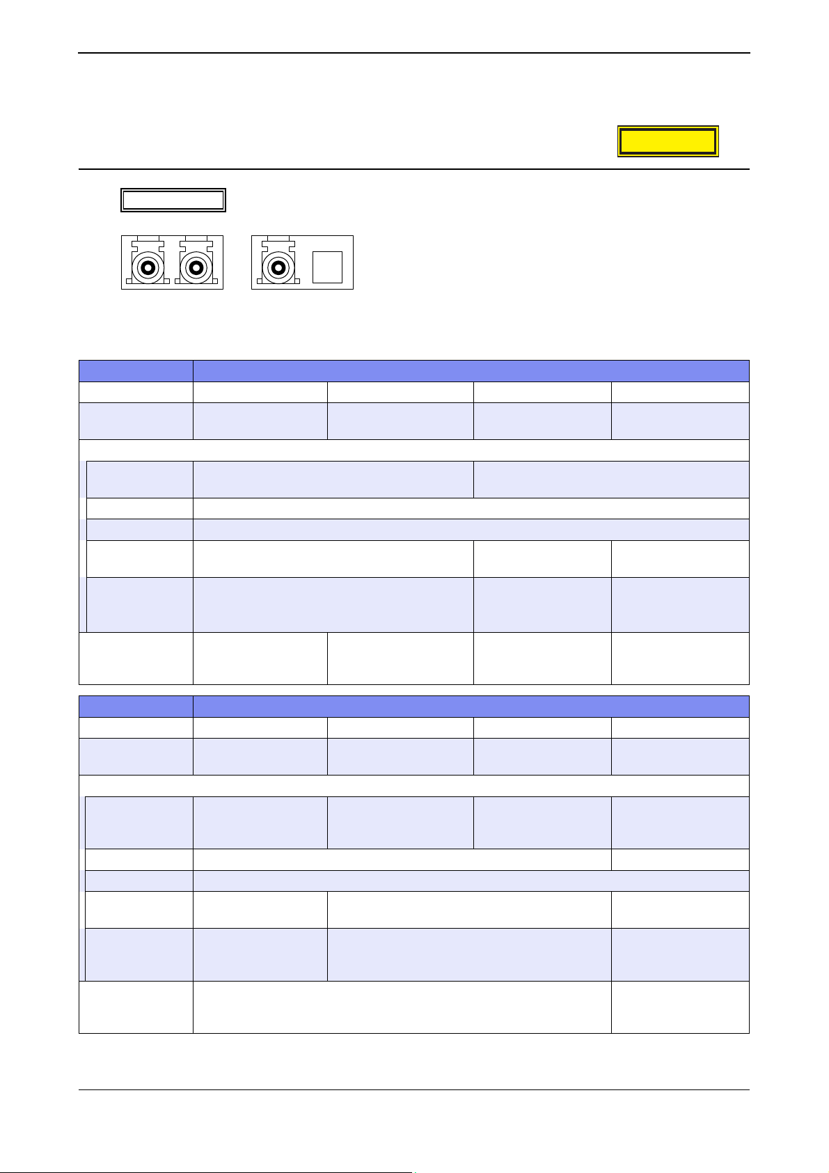
XG Series User's Guide Chapter 1 Features and Functions
1.1.2 Option
SFP Module
CLASS1LASERPRODUCT
AvailableModel
100BASE-FX
1000BASE-SX
1000BASE-LX
1000BASE-ZX
item specification
Vendor PN HFBR-5710L FTLF8519P2BNL HFCT-5710L SCP6P44-F7-BMH
Vendor Name AGILENT
Interface
specifications IEEE802.3z
Baud rate (bps) 1000M
connector LC connector
stressed receiver
sensitivity
cable length
(maximum)
(*3)
CLASS 1 LASER
PRODUCT
specifications
XG0224 / XG0448
1000BASE-BX-D
1000BASE-BX-U
TECHNOLOGIES
(1000BASE-SX Interface)
-17dBm or more -20dBm or more -19.5dBm or more
500m (MMF:50µm),
300m (MMF:62.5
EN60825-1:1994+A11,
EN60825-2:1994+A1
FINISAR
µm)
EN608251:1994+A11+A2,
EN60825-2:2004
AGILENT
TECHNOLOGIES
IEEE802.3z
(1000BASE-LX Interface)
550m (MMF:50µm,
µm),
62.5
5km (SMF:10
EN60825-
1:1994+A1+A2
µm)
SUMITOMO ELECTRIC
550m (MMF:50µm,
µm),
62.5
10km (SMF:10
IEC60825-1:2001
µm)
item specification
Vendor PN SCP6P94-F7-BMH SBP6F54-F1-BN-49 SBP6F54-F1-BT-31 HFBR-57E0P
Vendor Name
Interface
specifications –
Baud rate (bps) 1000M 100M
connector LC connector
stressed receiver
sensitivity
cable length
(maximum)
(*3)
CLASS 1 LASER
PRODUCT
specifications
SUMITOMO ELECTRIC SUMITOMO ELECTRIC SUMITOMO ELECTRI
IEEE802.3ah
(1000BASE-ZX
Interface)
-24dBm or more -21dBm or more -31dBm or more
70km (SMF:10µm) 20km (SMF:10µm) 2km (MMF:50µm)
(1000BASE-BX-D
Interface)
IEC60825-1:2001 EN60825-
IEEE802.3ah
(1000BASE-BX-U
Interface)
ABAGO
TECHNOLOGIES
IEEE802.3u
(100BASE-FX
Interface)
1:1994+A1+A2
*1) Please make sure to use 1000BASE-BX-D SFP module and 1000BASE-BX-U SFP module in pairs.
25
Hardware Specifications
Page 26
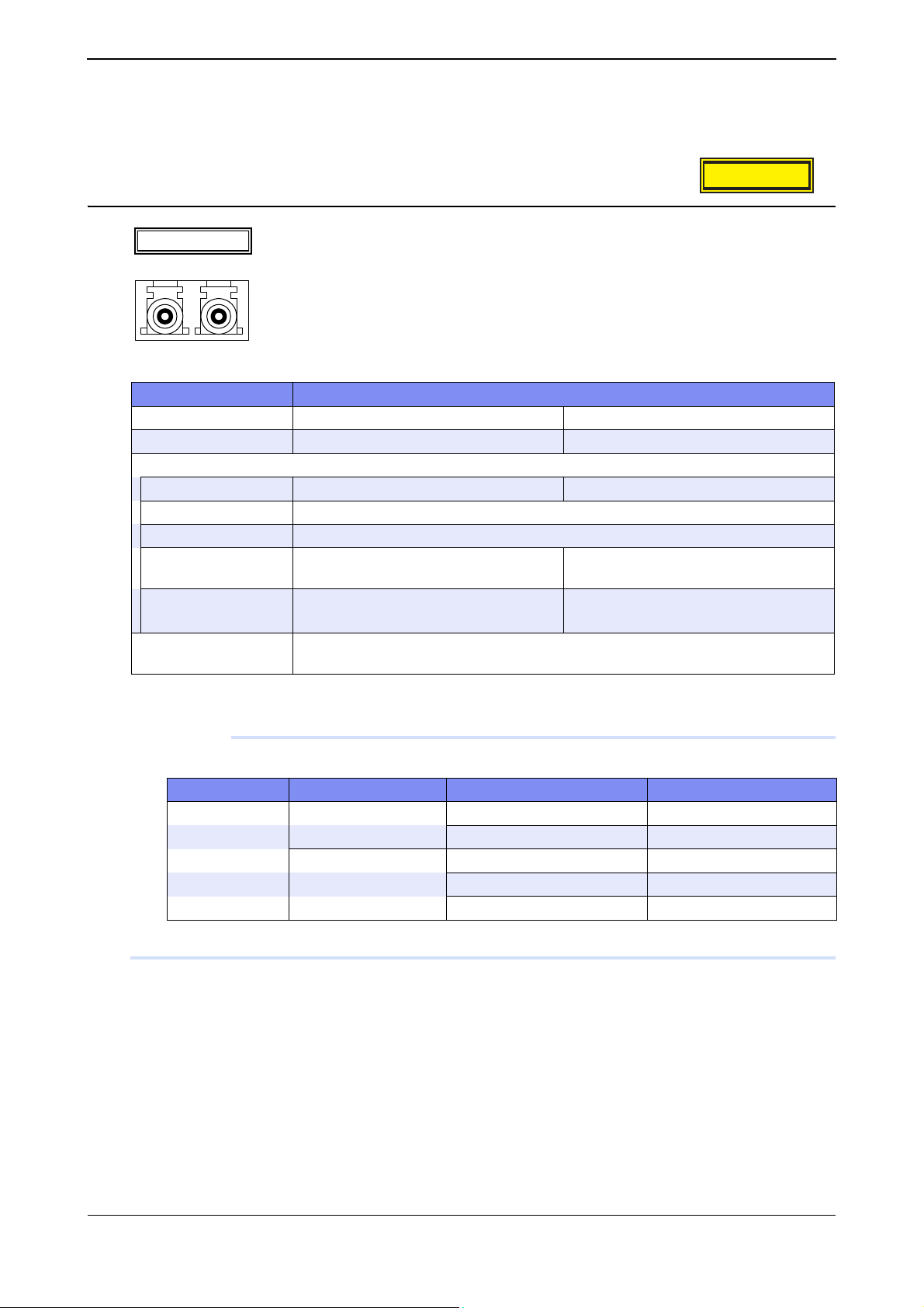
XG Series User's Guide Chapter 1 Features and Functions
*2) Applicable to XG0224 only.
*3) Cable length (maximum) is under the condition that the stressed receiver sensitivity satisfy the permissible level.
SFP+ Module
AvailableModel
10GBASE-SR/LR
item specification
Vendor PN FTLX8571D3BCL FTLX1471D3BCL
Vendor Name FINISAR FINISAR
Interface
specifications IEEE802.3ae (10GBASE-SR) IEEE802.3ae (10GBASE-LR)
Baud rate (bps) 10G
connector LC connector
stressed receiver
sensitivity
cable length (maximum)
(*)
CLASS 1 LASER
PRODUCT specifications
XG0448 / XG2600
-7.5dBm or more -10.3dBm or more
300m (MMF:50µm) 10km (SMF:10µm)
EN60825-1:1994+A1+A2, EN60825-2:2004
CLASS1LASERPRODUCT
*) Cable length (maximum) is under the condition that the stressed receiver sensitivity satisfy the permissible level.
Precautions
Cable length is as follows depending on the specifications of optical fiber cables.
Type Core / Clad diameter Minimum transmission band cable length (maximum) (m)
MMF 62.5/125
50/125
Please use the most appropriate cable according to the environment of the installed place.
µm 160MHz/km 26
200MHz/km 33
µm 400MHz/km 66
500MHz/km 82
2000MHz/km 300
26
Hardware Specifications
Page 27

XG Series User's Guide Chapter 1 Features and Functions
SFP+ Expansion Card
AvailableModel
item specification
Type name SJ10GSFPZ
Interface (ETHER)
specifications IEEE802.3ae (10GBASE-R Interface)
number of ports 2
Baud rate (bps) 10G
connector SFP connector
XG0224 / XG0448
CX4 Expansion Card
AvailableModel
item specification
Type name SJ10GCX4Z
Interface (ETHER)
specifications IEEE802.3ak (10GBASE-CX4 Interface)
number of ports 2
Baud rate (bps) 10G
connector 16pin, CX4connector
cable length (maximum)
(m)
XG0224 / XG0448
15
Compact Flash Card
AvailableModel
item specification
Capacity (MBytes) 256
XG0224
Power Cable (100V)
AvailableModel
item specification
cable length (m) 3
All models
27
Hardware Specifications
Page 28
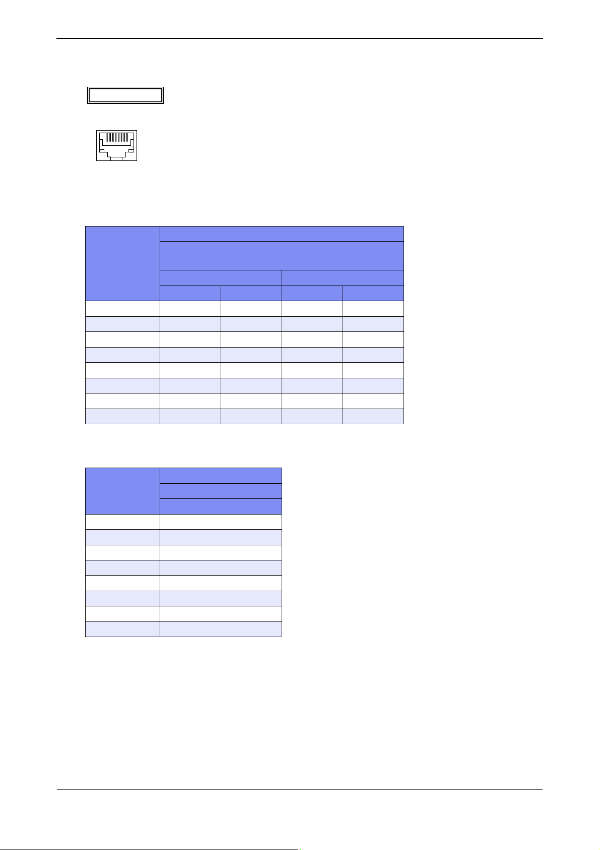
XG Series User's Guide Chapter 1 Features and Functions
1.1.3 10/100/1000BASE-T Port Specifications
AvailableModel
8
1
connectorisRJ458pin
• XG0224 / XG0448
Pin numbering
1 TD+ RD+ TP0+ TP1+
2 TD- RD- TP0- TP1-
3 RD+ TD+ TP1+ TP0+
4 – – TP2+ TP3+
5––TP2-TP3-
6 RD- TD- TP1- TP0-
7 – – TP3+ TP2+
8 – – TP3- TP2-
All models
–: Not supported
Signal name
(XG0224: 1 to 24 port)
(XG0448: 1 to 48 port)
10/100BASE-TX 1000BASE-T
MDI MDI-X MDI MDI-X
•XG2600
Pin numbering
1TD+
2 TD-
3RD+
4 –
5–
6 RD-
7–
8 –
–: Not supported
Signal name
10/100BASE-TX
MDI
28
Hardware Specifications
Page 29
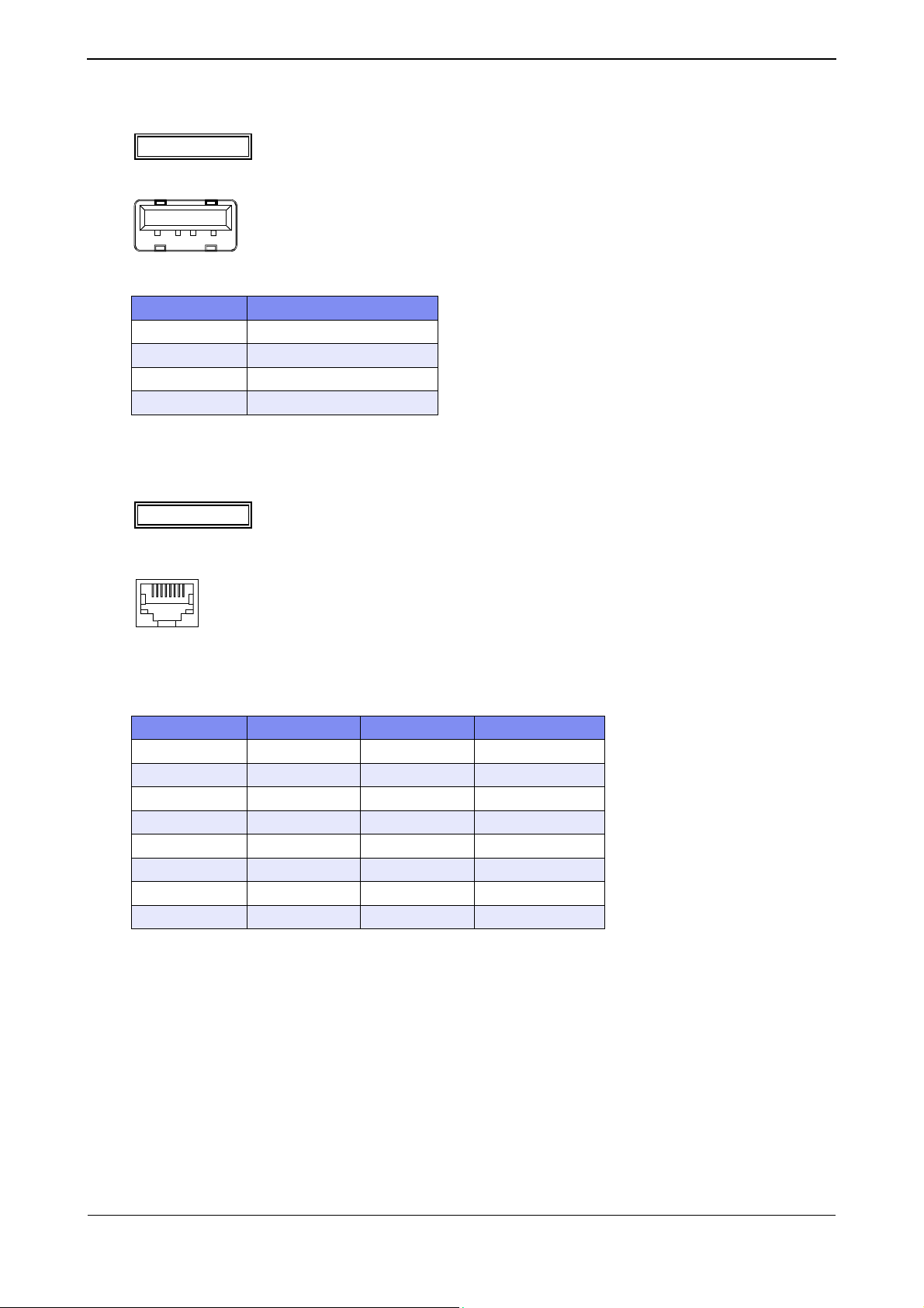
XG Series User's Guide Chapter 1 Features and Functions
1.1.4 USB Port Specifications
AvailableModel
1234
Pin numbering Signal name
1VBUS
2 D-
3D+
4 GND
XG0448 / XG2600
1.1.5 Console Port Specifications
AvailableModel
8
1
All models
connectorisRJ458pin
Astraightcableisused.
–: Not supported
Pin numbering Signal name in / out Content
1–– –
2 ER out data terminal ready
3 TD out send data
4 GND – ground
5 GND – ground
6 RD in receive data
7–– –
8 – – –
29
Hardware Specifications
Page 30

XG Series User's Guide Chapter 1 Features and Functions
1.2 Software Specifications
This section explains the software specifications for the device.
1.2.1 Software Specifications
❍: Supported, –: Not supported
Item
Forwarding Mode
VLAN
Port VLAN
Tag VLAN
Protocol VLAN
Link Down Relay
Link aggregation
Static
LACP
Back up port
STP
STP
MSTP
RSTP
LLDP
LLMNR
QoS
QoS sending algorithm
strict
DRR – –
WRR
Assign the priority to the queue
CoS
IPv4 TOS (ip precedence)
IPv6 TC
IPv4 DSCP
IPv6 DSCP
XG0224 XG0448 XG2600
Store and
Forward
❍❍❍
❍ ❍ ❍
❍❍❍
❍ ❍ ❍
❍ ❍ ❍
❍❍❍
❍ ❍ ❍
❍ ❍ ❍
❍❍❍
❍ ❍ ❍
❍❍❍
❍ ❍ ❍
❍❍❍
❍❍
❍❍❍
❍
(with the use of
ACL)
❍
(with the use of
ACL)
❍
(with the use of
ACL)
❍
(with the use of
ACL)
Features
Store and
Forward
❍
(with the use of
ACL)
❍
(with the use of
ACL)
❍
(with the use of
ACL)
❍
(with the use of
ACL)
Selectable
❍
–
❍
(with the use of
ACL (*1))
–
❍
(with the use of
ACL (*1))
–
30
Software Specifications
Page 31

XG Series User's Guide Chapter 1 Features and Functions
Item
XG0224 XG0448 XG2600
Features
Rewrite the priority
COS (user priority)
IPv4 TOS (ip precedence)
IPv4 DSCP
IPv6 DSCP
❍
(with the use of
ACL)
❍
(with the use of
ACL)
❍
(with the use of
ACL)
❍
(with the use of
ACL)
❍
(with the use of
ACL)
❍
(with the use of
ACL)
❍
(with the use of
ACL)
❍
(with the use of
ACL)
(with the use of
(with the use of
Security
IP/MAC filtering ❍ ❍ ❍ (*1)
Log in password
❍❍❍
Application filtering (per application server) ❍ ❍ ❍
IPv4 filter
IPv6 filter
RADIUS client
Loop detection
Broadcast/multicast storm control
MAC table flash
Port mirroring
ether L3 watch
❍
(with the use of
ACL)
❍
(with the use of
ACL)
❍❍❍
❍ ❍ ❍
❍❍❍
❍ ❍
❍❍❍
❍ ❍ ❍
❍
(with the use of
ACL)
❍
(with the use of
ACL)
(with the use of
Output rate control – –
Routing
IPv4
Static
❍ ❍ ❍
Multicast
IGMP snoop (v1, v2)
❍ ❍ ❍
ProxyDNS
DNS server
DNS relaying
URL filtering
SNMP Agent (v1, v2c, v3)
❍ ❍ ❍
❍❍❍
❍ ❍ ❍
❍❍❍
Means of configuration
telnet
ssh
Serial (CLI)
WWW browser (Web UI)
❍❍❍
❍ ❍ ❍
❍❍❍
❍ ❍ ❍
–
❍
ACL (*1))
❍
ACL (*1))
–
❍
ACL)
–
–
❍
31
Software Specifications
Page 32

XG Series User's Guide Chapter 1 Features and Functions
Item
Logging
System logging
Error logging
Automated time adjustment
Scheduling
Compact flash
USB memory –
XG0224 XG0448 XG2600
❍ ❍ ❍
❍❍❍
❍ ❍ ❍
❍❍❍
❍
*1) For the packets which applied MAC/IP filter, QoS function with the use of ACL become void.
1.2.2 Initial Values
Item
Port information
ETHER port
Copper/Fiber
Full/half duplex
MDI/MDI-X
Flow control
VLAN VID 1 (no tag) –
Protocol VLAN
Predefined protocol IPv4, IPv6, FNA
Link aggregation
Load balancing algorithm tx MAC address XOR rx MAC address
Back up port
Port selection scheme Master ports preferred
STP information
STP operating mode STP used Disabled
LLDP Disabled Used
LLMNR Enabled (lan 0,vlan1) Disabled Enabled
Loop detection Disabled
Broadcast/Multicast storm control Disabled
Egress Rate Control – Disabled
IGMP snoop Disabled
1-20 21-24 25-26 1-44 45-48 49-52 1-26
XG0224 XG0448 XG2600
–
Auto-detect – Auto-detect –
Auto-detect – Auto-detect – –
Auto-
detect
––
tx: OFF, rx: ON
Features
Auto-
detect
Features
– –
❍❍
–: Not supported
Manage
ment port
10/
10Gbps
–
(Fixed)
Full-
duplex
(Fixed)
100Mbps
(Auto-
detect)
Auto-
detect
MDI
(Fixed)
tx: OFF
(Fixed)
rx: ON
(Fixed)
32
Software Specifications
Page 33

XG Series User's Guide Chapter 1 Features and Functions
Features
oob Interface
(Management
port):enable IPv6,
IP interface
Item
XG0224 XG0448 XG2600
lan0 Interface:enable IPv6, enable LLMNR
enable LLMNR
RADIUS client Disabled
Password information
User name admin
Password None
ACL information None
ProxyDNS information None
SNMP Disabled
telnet/SSH auto logoff 5 min.
Console auto logoff 8 hour
Web browser auto logoff 10min (Fixed)
System log information
Sending to the Server Disabled
Facility 23 (local7)
Priority error, warn, info
Security proxydns
Automatically current time Set Disabled
Schedule information None
Host database information None
Compact flash dump Disabled –
USB memory dump – Disabled –
33
Software Specifications
Page 34

XG Series User's Guide Chapter 1 Features and Functions
1.2.3 System Maximum Values
–: Not supported
(*4)
(*5)
(*6)
(*6)
(*6)
(*6)
(*7)
(*7)
Features
64 (per device)
(*8)
–
–
64 (per device)
(*8)
64 (per device)
(*8)
64 (per device)
(*8)
–
–
Item
Bridge information
# of blocks registered (*1) 16000 32000 16000
# of static blocks registered 400
VLAN definition
# of VLANs (*2) 4094
# of Protocol VLAN unlimited 16 VLAN
User defined Protocol VLAN 8
Link aggregation
# of member ports 8 10
# of groups 13 26 10
Back up ports
# of groups 13 26 13
STP information
# of MSTP instances 16
# of neighbor LLDP device information (*3) 26+364 52+728 26+364
MAC filters
IPv4
IPv6
Rewrite the priority
IPv4
COS (user priority) 128 (per device)
IPv4 TOS (ip precedence) 128 (per device)
IPv4 DSCP 128 (per device)
Assign the priority to the queue 128 (per device)
IPv6
IPv6 DSCP 128 (per device)
Assign the priority to the queue 128 (per device)
MAC table Flushing
# of address group 4 –
# of VLAN for every address group 50 –
IGMP snoop
# of multicast group addresses registered 200 2000
Port mirroring
Tar g e t p o rt 1 tx: 1, rx: 1 (*9)
XG0224 XG0448 XG2600
128 (per device)
128 (per device)
34
Software Specifications
Page 35

XG Series User's Guide Chapter 1 Features and Functions
(*4)
(*5)
(*6)
(*7)
Features
64 (per device)
(*8)
–
64 (per device)
(*8)
–
Item
# of ARPs registered 8000
static 200 –
# of IPv4 interfaces 100 100 (*10)
# of IPv6 interfaces 100 100 (*10)
RA information (IPv6)
# of interface receiving RA 2
# of Default Router for every interface 4
# of IPv6 prefix for every interface 4
# of Neighbor Cache entry 8000
Routing table (IPv4)
# of routes registered 200
# of static routes registered 200
Routing table (IPv6)
# of routes registered 200
# of RA routes registered 1
# of static routes registered 200
IP filtering information
IPv4 128 (per device)
IPv6 128 (per device)
DSCP rewrite information
IPv4 128 (per device)
IPv6 128 (per device)
# of ACL definitions 800 300
# of host database definitions 100
AAA information
# of groups 10
# of defined authenticated users 1000
# of defined RADIUS servers 4
ProxyDNS 50
SNMP information
# of max. SNMP managers registered 8
# of simultaneously connected telnet/ssh/WWW browser clients (*11) 8
System logging
# of displayed system log records 1024 or more
Max. # of system log servers registered 3
Automated time adjustment
Max. # of SNTP servers registered 4
# of schedules defined 20
Application filtering information (per application server) 30
XG0224 XG0448 XG2600
*1) Includes own entries of the device and static entries.
*2) Includes system use of VLANs (number of ether ports + 1).
35
Software Specifications
Page 36

XG Series User's Guide Chapter 1 Features and Functions
*3) First, the maximum number of neighbor LLDP device information is 15 times of the number of total ports including
1G and 10G. (XG0224: 390, XG0448: 780, XG2600: 390)
Second, each port including 1G and 10G must have at least one LLDP information. (XG0224: 26, XG0448: 52,
XG2600: 26)
The remaining number of neighbor LLDP device information can be distributed to any ports. (XG0224: 364,
XG0448: 728, XG2600: 364)
*4) Total number of MAC filter (IPv4) and IPv4 filter definitions.
*5) Total number of MAC filter (IPv6) and IPv6 filter definitions.
*6) Total number of Rewrite the priority (IPv4) and IPv4 DSCP rewrite definitions.
*7) Total number of Rewrite the priority (IPv6) and IPv6 DSCP rewrite definitions.
*8) The total number of MAC filter, IPv4 filter, MAC QoS and IPv4 DSCP rewrite definitions may be reduced as the
number of ACL rules increase.
*9) Same port can't be used as a target port for tx and for rx.
*10) Includes Management Port Interface (oob).
*11) 4 sessions for Telnet, 1session fot WWW (http), 1session for console, 1session for ftp, 1session for ssh (sftp).
36
Software Specifications
Page 37

Chapter 2
Using the CLI
This chapter describes how to use the command line interface (CLI) to operate the device.
2.1 Overview of the CLI. . . . . . . . . . . . . . . . . . . . . . . . . . . . . . . . . . . . . . . . . . . . . . . . . . . . . . . . . . . . . . . . . 38
2.1.1 Operating Environment for the CLI . . . . . . . . . . . . . . . . . . . . . . . . . . . . . . . . . . . . . . . . . . . . .38
2.1.2 Command Modes and Mode Switching . . . . . . . . . . . . . . . . . . . . . . . . . . . . . . . . . . . . . . . . . . 39
2.2 Using the CLI . . . . . . . . . . . . . . . . . . . . . . . . . . . . . . . . . . . . . . . . . . . . . . . . . . . . . . . . . . . . . . . . . . . . . . 43
2.2.1 Using the Shell Function. . . . . . . . . . . . . . . . . . . . . . . . . . . . . . . . . . . . . . . . . . . . . . . . . . . . . . 43
2.2.2 Error Messages Common to All Commands. . . . . . . . . . . . . . . . . . . . . . . . . . . . . . . . . . . . . . 53
2.2.3 Characters that can be entered . . . . . . . . . . . . . . . . . . . . . . . . . . . . . . . . . . . . . . . . . . . . . . . . 54
Page 38

XG Series User's Guide Chapter 2 Using the CLI
2.1 Overview of the CLI
This section describes how to use the command line interface (CLI) for the XG Series.
2.1.1 Operating Environment for the CLI
There are two ways to access the device to run commands.
• Serial connection
Connect to the serial port of the device using RS232C cable via RJ45conversion cable.
The available terminal emulation type is VT100.
When initially connecting a terminal to the device, configure the serial port on the client side as shown below.
Item Setting value
Baud rate 9600 bps
Character size 8 bit
Parity None
Stop bits 1 bit
Flow control None
Emulation VT100
Character set ASCII
Line feed code Transmission: CR (carriage return) only
Reception: LF is added
• Remote connection via LAN port
Connect a terminal or host computer using a telnet client to the management LAN port of the device TCP port of 23
Is used for the default telnet connection
The following tables list the factory defaults.
Management-LAN [XG2600] and LAN Interface initial settings
Item Setting value
IP address None (must be set before using the LAN interface)
Subnet address None (must be set before using the LAN interface)
Telnet server initial settings
Item Setting value
Use telnet Enable
Port number 23 (TCP)
Emulation VT100/VT200/xterm
BackSpace key Delete
Character set ASCII
To use the remote connection via the management-LAN port, use the "oob ip" command to configure the managementLAN port for the device as below. [XG2600]
XG2600(config)# oob ip 192.168.1.1/24 3
XG2600(config)# commit
XG2600(config)# save
To use the remote connection via the LAN port 1, use the "lan ip" command to configure the management-LAN port
38
Overview of the CLI
Page 39

XG Series User's Guide Chapter 2 Using the CLI
for the device as below.
XG2600(config)# ether 1 vlan untag 1
XG2600(config)# lan 0 vlan 1
XG2600(config)# lan 0 ip 192.168.1.1/24 3
XG2600(config)# commit
XG2600(config)# save
A VT100, VT200, or xterm can be used as a terminal.
2.1.2 Command Modes and Mode Switching
The following table shows a hierarchy of command modes and mode switching.
2.1.2.1 Command Operation Procedure
The flow of system operation via command execution is as follows:
1) Login to the device.
2) Run an operation command to manage system operations.
3) Run a configure command to move to configuration mode.
4) Run a configuration command to set candidate configuration (candidate-config).
5) Run a commit command to apply the candidate configuration as a running configuration (running-config).
6) Run a save command to save the candidate configuration as a startup configuration (startup-config).
7) Run an exit or similar command to return to operation mode.
8) Repeat steps 2) through 7)
9) Run an exit command to log out.
Reference
Login
username
admin
" Login to the device" (pg.40), "2.1.2.2 Executable commands" (pg.42)
Operationmode
user
exit
exit
Operationcommand
User
class
admin/su
exit/!
Runningconfiguration
(running-config)
Admin
class
reset/Reconnectpower
configure
exit/!/end/quit
commit
load
Configurationmode
Admin
class
Operationcommand
Configurationcommand
Candidateconfiguration
(candidate-config)
save
load
Startupconfiguration
(startup-config)
39
Overview of the CLI
Page 40

XG Series User's Guide Chapter 2 Using the CLI
Login to the device
When you connect to the device via a console port, telnet, or ssh connection (*1), a login prompt like the following one
appears:
Login: Enter user name (*1)
Password: Enter password.
<WARNING> weak admin’s password:set the password (*2)
# Commands can be run. (*3)
By entering the user name and password, you can run commands.
Only the administrator can log into the system for the first time. For the first time, enter "admin" for the user name, and
press ENTER for the password.
*1) For ssh connections, "Login:" does not appear. Specify the user name at the ssh client.
*2) This message warns you that system security is weak because the password is not set. This message will not appear
after you set a password with 8 or more alphanumeric characters and symbols.
*3) The model name is also shown in the prompt by default. When a prompt character string is configured, the configured
prompt is displayed.
User name and password
The user name and password are different for the administrator and general users.
•User name
The username for the administrator is "admin" and the user name for the general user is "user" (fixed user names).
By using a password aaa command and specifying use of AAA user information (aaa user id command) or RADIUS
server user information as the login user information, you can add user names as an administrator or general user.
• Password
No password is configured by default. Be sure to configure the password when you log into the system for the first
time. Use the password admin set command to configure the administrator password and the password user set
command to configure the general user password. When configuring password aaa command settings, set the
administrator and user passwords in the AAA user information stored in the system (aaa user password command) or in
the user information for the RADIUS server.
Reference
"5.14 Password Information" (pg.257)
40
Overview of the CLI
Page 41

XG Series User's Guide Chapter 2 Using the CLI
Privilege classes (admin class and user class)
Two privilege classes are available; admin class (login as admin) and user class (login as user).
• admin class
All commands can be run.
However, admin commands and su commands cannot be run because it is not necessary to run them in admin class.
•user class
Only a portion of operation commands can be run. Configuration commands cannot be run. You can run an admin
command to transfer to admin class.
If a password aaa command has been used to specify use of the AAA user information (aaa user id command) or RADIUS
server user information as the login user information, the user name privilege class is determined as follows:
• When using RADIUS server
Determined according to the Filter-ID attribute information configured in the RADIUS server.
RADIUS attribute (number) Setting
Filter-ID (11) For admin class : ”administrator”
For user class : ”user”
• When using user information on the device
Determined according to aaa user user-role command settings.
Use modes (operation mode and configuration mode)
Two use modes are available; operation mode and configuration mode.
• Operation mode
Only operation commands can be run.
• Configuration mode
Both configuration commands and operation commands can be run.
The use mode immediately after logging into the system is operation mode.
The table below displays user names and corresponding passwords, as well as privilege class and use mode after login.
Login user
name
admin None
user Not set
*) To log into the system as user, configure password information for the user.
Default password
information
(blank) (Hit ENTER)
(login not possible [*])
Password configuration
command
password admin set admin class Operation mode
password user set user class Operation mode
Login privilege
class
Login use mode
41
Overview of the CLI
Page 42

XG Series User's Guide Chapter 2 Using the CLI
2.1.2.2 Executable commands
Command execution is restricted according to the following conditions:
• Command type
• Privilege class
• Use mode
Reference
" Privilege classes (admin class and user class)" (pg.41),
" Use modes (operation mode and configuration mode)" (pg.41)
Command type (operation commands and configuration commands)
Two command types are available; operation commands and configuration commands.
Since the use mode after logging into the system is operation mode, you can only run operation commands.
By running a configure command, the use mode changes to configuration mode and you will be able to run configuration
commands as well as operation commands.
However, since you cannot run a configure command in user class, run an admin command to change to admin class before
running the configure command.
The following table lists command types and functions.
Command type Command function
Operation command Display and manipulate device status, operation status, and
network status, display or delete stored information, etc.
Configuration command Operating information settings and network configuration,
etc.
The following table lists commands and operations.
Command Operation
Configuration command Sets to candidate configuration (candidate-config).
These are basically not reflected in running operations; however, as in password
information configuration, there are commands to reflect settings immediately.
commit command The candidate configuration is reflected in the running configuration (running-
config) and active operations change.
Reference
Reference
save command Saves candidate configuration to startup configuration (startup-config).
Run reset command or reconnect
power
show candidate-config command Displays candidate configuration settings.
show running-config command Displays active configuration settings.
show startup-config command Displays startup configuration settings.
delete command Deletes configuration settings.
Applies candidate configuration to the running configuration.
"5.48 Effect by "commit" Command Execution" (pg.543)
Precautions
If you run a reset command or reconnect power without first running a save command, the running configuration and
candidate configuration will return to the state they were in before running a configuration command.
42
Overview of the CLI
Page 43

XG Series User's Guide Chapter 2 Using the CLI
2.2 Using the CLI
2.2.1 Using the Shell Function
The shell function supports the following features in order to assist command entry:
• Command execution function
• Entry editing function
• Command name autocomplete function
• Command argument autocomplete function
• Abbreviated command entry function
• Command alias function
• Configuration hierarchy function
• Time of command execution display function
• Command history function
The following describes each function.
2.2.1.1 Command execution function
The command execution function allows you to enter a command string and hit ENTER or RETURN to run the command.
You can enter ASCII characters, EUC kanji, or Shift JIS kanji characters for the command string.
To enter a kanji character, specify its code using a terminal charset command.
The maximum length of a command string is 1,022 characters (including the prompt string) for ASCII characters. A single
kanji character is equivalent to two ASCII characters.
2.2.1.2 Entry editing function
The entry editing function allows you to move the cursor, insert or delete characters, and delete, cut, and paste words
within an entered command string.
Refer to "2.2.1.10 List of shell key bindings" (pg.52) for keys used with the entry editing function.
The entry editing function uses the VT100 terminal escape sequence to move the cursor and perform other functions.
When cursor movement or other functions do not work correctly, check that the terminal software being used supports
VT100 terminal emulation. In addition, if the screen display is not set to 24 lines and 80 columns, use the terminal window
command to configure the screen correctly.
Reference
"2.2.1.10 List of shell key bindings" (pg.52)
43
Using the CLI
Page 44

XG Series User's Guide Chapter 2 Using the CLI
2.2.1.3 Command name autocomplete function
The command name autocomplete function allows you to display a list of command names without entering anything by
pressing the TAB key or CTRL + I. In addition, if you press the TAB key or CTRL + I after entering part of a command,
the command string will be automatically completed. Automatically completed character strings differ depending on
conditions.
The following table details autocomplete operations for entered characters.
Command name beginning with entered characters Operation
When nothing is entered A list of all command names is displayed.
When a single command applies The applicable command name is automatically completed
along with a single blank character.
When multiple commands apply, with the same string
following the entered characters
When multiple commands apply, with different strings
following the entered characters
When no command applies Nothing is displayed.
When you use autocomplete without entering anything, a list of commands with the command-type lines shown below is
displayed.
The identical character string portion is completed.
A list of possible commands is displayed.
• --Exec commandsOperation commands and alias commands
• -- Exec commands (config mode)-Operation commands and aliases for configuration mode
• --Config commands-Configuration commands
• --Config commands (current directory)-Configuration command arguments (when the configuration hierarchy function is enabled and you are not in the top
hierarchy)
The command name autocomplete function works differently according to the number of times you hit the TAB key or
CTRL + I.
The table below lists the autocomplete operation for each number of times the TAB key or CTRL + I are hit.
Note that descriptions are displayed in Japanese (kanji characters). If they are not displayed correctly, use a terminal
charset command to specify a kanji character code which is displayed correctly.
Number of times the TAB
key or CTRL + I are hit
One time A list of command names is displayed or the entered command string is automatically
completed.
Two times Command and argument names corresponding to the use mode and their descriptions are
displayed.
In operation mode, the operation command names and descriptions, and the names of
commands registered using an alias command as well as their registration content are
displayed.
In configuration mode when the configuration hierarchy function is disabled, the
configuration command names and their descriptions are displayed.
In configuration mode, when the configuration hierarchy function is enabled and you are at
the top hierarchy level, the configuration command names and descriptions are displayed.
In configuration mode, when the configuration hierarchy function is enabled and you are not
at the top hierarchy level, the command argument names available for the current hierarchy
level and their descriptions are displayed.
Operation
44
Using the CLI
Page 45

XG Series User's Guide Chapter 2 Using the CLI
Number of times the TAB
key or CTRL + I are hit
Operation
Three times Command forms are displayed.
In operation mode, simplified command forms are displayed.
In configuration mode, when the configuration hierarchy function is disabled, simplified
command forms are displayed.
In configuration mode, when the configuration hierarchy function is enabled and you are at
the top hierarchy level, simplified command forms are displayed.
In configuration mode, when the configuration hierarchy function is enabled and you are not
at the top hierarchy, command forms for the current hierarchy level and simplified command
forms are displayed.
Four times Returns to the operation for hitting the TAB key or CTRL + I one time.
45
Using the CLI
Page 46

XG Series User's Guide Chapter 2 Using the CLI
2.2.1.4 Command argument autocomplete function
While entering configuration command arguments, the command argument autocomplete function allows you to display a
list of arguments and candidate arguments without entering anything by pressing the TAB key or CTRL + I. In addition, if
you press the TAB key or CTRL + I after entering part of an argument, the remaining character string will be automatically
completed.
The argument autocomplete function works differently according to the number of times you hit the TAB key or CTRL + I.
The table below lists the autocomplete operation for each number of times the TAB key or CTRL + I are hit.
Note that descriptions are displayed in Japanese (kanji characters). If they are not displayed correctly, use a terminal
charset command to specify a kanji character code which is displayed correctly.
Number of times the TAB
key or CTRL + I are hit
One time A list of arguments and argument candidates is displayed or the entered argument
string is autocompleted.
This works in the same way as command name autocomplete.
Two times Descriptions of arguments and argument candidates are displayed.
Three times The command syntax following the current argument is displayed.
Four times Returns to the operation for hitting the TAB key or CTRL + I one time.
For some command arguments, you can specify multiple arguments separated by a comma (,), or specify a range of values
Note
delimited by a hyphen (-). The argument autocomplete function assumes that all arguments allow specifying multiple arguments
and value range, and if you autocomplete an argument after entering "," or "-", all the argument candidates will be given.
Operation
2.2.1.5 Abbreviated command entry function
The abbreviated command entry function allows you to run a command with its name and argument entered only partway.
For each command name and command argument entered, the command name autocomplete and command argument
autocomplete are performed and the command is executed. When there are multiple candidates, enter characters until
candidates are narrowed to one, and then execute the command. If you execute the command while there are still multiple
candidates, the command is not autocompleted and an error occurs.
2.2.1.6 Command alias function
The command alias function allows you to register a command name and its argument(s) as a single command.
Use the alias command to register, delete, and display command aliases.
Note that commands registered with a command alias cannot be autocompleted by the abbreviated command entry
function, and you must enter the complete command name and arguments when registering them.When a command alias is
registered correctly, it will be included for command name and argument autocomplete.
46
Using the CLI
Page 47

XG Series User's Guide Chapter 2 Using the CLI
2.2.1.7 Configuration hierarchy function
The configuration hierarchy function interprets common portions of executed configuration command names and
arguments as a hierarchy level, and allows you to move between hierarchy levels.
When you execute a configuration command and the command completes successfully, in general the portion from the
command name to the argument two arguments before an argument specifying a variable value becomes a hierarchy level.
This may differ depending on the command.
Ex.)
(argument with variable value)
(configure)# lan 0 ip
(Move hierarchy level to the argument two before the variable value argument)
(configure-lan-0-ip)#
Even in cases where an error occurs because the number of arguments is less than required, the configuration hierarchy
function assumes the entered command name and arguments to be a hierarchy level. Depending on the command, even if
arguments are incorrect the configuration hierarchy function may judge that there are not enough arguments and interpret
the entry as a hierarchy level. The portion assumed to be a hierarchy level is displayed at the command prompt. However,
if you have used a terminal prompt command to change the entry prompt string to exclude the configuration hierarchy, it is
not displayed.
After moving to a hierarchy level, you can only enter command arguments following the current level to execute the
command. When the number of arguments is still not enough, a further hierarchy level is displayed. When you have
omitted an optional argument, without moving to another hierarchy level the command is executed correctly, following
which you will move to a higher hierarchy level. Be sure to enter optional arguments as a group. To execute a command
other than at the hierarchy level you have moved to, enter it beginning with the command name.
However, in a hierarchy level for an argument which allows for arbitrary character strings, any strings other than the
commands below will be entered as configuration command arguments. To enter one of the following commands as an
argument for a configuration command, move to a higher level, and then enter so that strings matching these commands
are the second argument or following.
exit, !, end, quit, up, top, delete, show, clear, commit, discard, save, load, reset,
Comment line beginning with #
Ex.)
address 192.168.0.1/24 3
(configure)# acl 0 ip (Moves to another level because there are not enough arguments.)
(configure-acl-0-ip)# any (Moves to another level because there are not enough arguments.)
(configure-acl-0-ip-any)# any (Moves to higher level because command can complete successfully
without specifying an optional argument.)
(configure-acl-0)#
If you run the show command with no arguments after moving hierarchy levels, a list of configuration commands for that
level and following is displayed.
You can move to a higher hierarchy level or to the top level using an up command or top command respectively.
The configuration hierarchy function is disabled by default. Even when it has been enabled, this function is disabled after
you log out of the system. In this case, no message is displayed to indicate that the function has been disabled.
The following explains how to enable and disable the configuration hierarchy function.
• To enable the configuration hierarchy function: Press CTRL + O in configuration mode.
The following message is displayed and the configuration hierarchy function is enabled. Information which has been
partially entered will not be discarded.
<NOTICE> The configuration directory mode is enabled. To disable, type Ctrl+G.
47
Using the CLI
Page 48

XG Series User's Guide Chapter 2 Using the CLI
• To disable the configuration hierarchy function: Press CTRL + G.
The following message is displayed and the configuration hierarchy function is disabled. Information which has been
partially entered will be discarded.
<NOTICE> The configuration directory mode is disabled.
A command execution example is shown below.
z Command
# configure
(config)# lan 0 ip address 192.168.1.1/24 3 (Run configuration command.)
(config-lan-0-ip)# (Hierarchy level is displayed at the command prompt.)
(config-lan-0-ip)# show (Display configuration following the current level.)
address 192.168.1.1/24 3
service server
info address 192.168.1.100/24 32
(config-lan-0-ip)# save
(config-lan-0-ip)# top (Move to the top level.)
(config)#
(Change to configuration mode.)
(Enter the command name and run the command.)
2.2.1.8 Time of command execution display function
The time of command execution display function allows you to display the time when the execution of a command starts.
This function is useful when a command execution log is being recorded during operations.
To enable the time of command execution display function, use the terminal timestamp command.
Although you can check command execution time with the show logging command, execution time is only displayed for
commands recorded in the command execution history. You can also use the terminal prompt command to display the date
and time in the prompt string However, this is not the time when a command was executed but the time when the prompt
was displayed.
2.2.1.9 Command history function
The command history function allows you to record command execution history and re-execute commands using this
history. You can also redisplay commands and replace commands in the history.
You can set the number of lines in the command history using a terminal logging command.
You can also press CTRL + P and CTRL + N to sequentially display the command history items, and re-execute or re-edit and
Note
execute a displayed command.
Reference
The following explains how to re-execute and redisplay commands.
You can use the history specifier and display specifier together with command character string replacement.
"2.2.1.10 List of shell key bindings" (pg.52)
48
Using the CLI
Page 49

XG Series User's Guide Chapter 2 Using the CLI
Re-executing commands
You can enter a history specifier at the beginning of the command string to re-execute the command. The command will be
executed after the command string for re-execution is displayed. In addition, command history and history numbers can be
viewed with the history command. Note that you can enter the history specifier only once at the beginning of the command
line. Any history specifiers entered thereafter will be treated as normal characters.
History specifier Operation
!! Re-execute the last command run.
! history number Re-execute the command with the specified history number.
!-number in history Re-execute the command run the specified number of commands before in the history.
Ex.) !-3 (The third command from the newest in the history is re-executed.)
! string The last run command beginning with the specified string is re-executed.
Ex.) !net (The last run command beginning with "net" is re-executed.)
When you enter a string following the history specifier, it will be added to end of the command string invoked from the
history.
The following shows an example.
z Command
# show ip route
(The execution results of show ip route are displayed.)
!! all (Add "all" to the last command and execute it.)
#
show ip route all (Display the command string to re-execute.)
(The execution results of show ip route all are displayed.)
Redisplaying commands
You can redisplay a previously run command by entering a display specifier (:p) following a history specifier. Note that the
displayed command is not re-executed yet.
Since the displayed command string is recorded as a new command history item, you can re-execute it by entering !! after
checking the command string.
Display specifier Operation
:p Redisplays a command.
Ex.) !net:p (The last run command beginning with "net" is redisplayed.)
When you enter a string following the display specifier, it will be added to end of the command string invoked from the
history.
A command execution example is shown below.
z Command
# show ip route
(The execution results of show ip route are displayed.)
# !!:p all (Add "all" to the last command executed and display it.)
show ip route al (Display the command string.)
# !! (Re-execute the previous command.)
show ip route all (Display the command string to re-execute.)
(The execution results of show ip route all are displayed.)
49
Using the CLI
Page 50

XG Series User's Guide Chapter 2 Using the CLI
Replacing the last command string
By entering a replacement specifier (^), replacement target string, and replacement string at the beginning of a command
string, you can re-execute the last command with the specified string replaced with a new string.
If no replacement string is specified, the target string will be deleted.
The table below lists specifiers and operations. (A: replacement target string, B: replacement string, C: additional string)
Command Operation
^A^B^ Replace A with B and execute the command string.
^A^B^:p Replace A with B and display the command string.
^A^B^C Replace A with B, add C to the command string, and execute it.
^A^B^:pC Replace A with B, add C to the command string, and display it.
^A^^ Delete A and execute the command string.
^A^^:p Delete A and display the command string.
^A^^C Delete A, add C to the command string, and execute it.
^A^^:pC Delete A, add C to the command string, and display it.
A command execution example is shown below.
z Command
# show running-config lan 0 ip address
(Display the IP address for lan 0.)
# ^addr^rout^:p (Replace addr with rout and display the command string.)
show running-config lan 0 ip routess
# ^ess^e^ (replace ess with e and execute the command string.)
show running-config lan 0 ip route (Display the command and execute it.)
(Display the static route information for lan 0.)
50
Using the CLI
Page 51

XG Series User's Guide Chapter 2 Using the CLI
Replacing command strings
By entering a single-replacement specifier (:s) or all-replacement specifier (:gs) following a history specifier and
replacement specifier, you can replace the target string and re-execute the command string.
A single-replacement specifier replaces the first matching string only, while an all-replacement specifier replaces all
matching strings.
The replacement target string and replacement string are specified as with string replacement for the preceding command;
however, arbitrary characters (@, #, %, &, ~, =, _, etc.) may be used as delimiters. You can successively enter a singlereplacement specifier, all-replacement specifier, and display specifier.
The table below lists specifiers and operations. This example uses "/" as a delimiter.
(A: replacement target string, B: replacement string, C: additional string)
Command Operation
:s/A/B/ Replace only the first instance of A with B and execute the command string.
:ps/A/B/ Replace only the first instance of A with B and display the command string.
:s/A/B/C Replace only the first instance of A with B, add C to the command string, and execute it.
:ps/A/B/C Replace only the first instance of A with B, add C to the command string, and display it.
:gs/A/B/ Replace all instances of A with B and execute the command string.
:pgs/A/B/ Replace all instances of A with B and display the command string.
:gs/A/B/C Replace all instances of A with B, add C to the command string, and execute it.
:pgs/A/B/C Replace all instances of A with B, add C to the command string, and display it.
:s/A// Delete only the first instance of A and execute the command string.
:ps/A// Delete only the first instance of A and display the command string.
:s/A//C Delete only the first instance of A, add C to the command string, and execute it.
:ps/A//C Delete only the first instance of A, add C to the command string, and display it.
:gs/A// Delete all instances of A and execute the command string.
:pgs/A// Delete all instances of A and display the command string.
:gs/A//C Delete all instances of A, add C to the command string, and execute it.
:pgs/A//C Delete all instances of A, add C to the command string, and display it.
:s/A1/B1/:gs/A2/B2/:p Replace only the first instance of A1 with B1, replace all instances of A2 with B2, and display the
command string.
A command execution example is shown below.
z Command
# lan 0 ip address 192.168.0.1/24 3
# !!:gs/0/1/:p (Replace all instances of 0 with 1 and display the command string.)
lan 1 ip address 192.168.1.1/24 3
# !! (Re-execute the last command to run.)
lan 1 ip address 192.168.1.1/24 3
When entering a command with the command history function, you can omit the last delimiter (/, ^, etc.) at the end of the
Note
command line. However, when the last delimiter is omitted, you cannot specify a display specifier (:p), additional history
specifier, or additional string.
51
Using the CLI
Page 52

XG Series User's Guide Chapter 2 Using the CLI
2.2.1.10 List of shell key bindings
The following table shows the key bindings for using the shell.
Key combination
(note)
Ctrl+A Moves the cursor to the top.
Ctrl+B ← (Note) Moves the cursor to the left by one character.
Ctrl+C Interrupts input.
Ctrl+D Deletes one character if any are input.
Ctrl+E Moves the cursor to the end.
Ctrl+F → (Note) Moves the cursor to the right by one character.
Ctrl+G Disables the configuration hierarchy function.
Ctrl+H BS BACKSPACE
Ctrl+I Tab Autocomplete/displays autocomplete candidate list/displays argument descriptions/
Ctrl+J Return Input complete
Ctrl+K Cuts from the cursor position to the end.
Ctrl+L Updates the screen.
Ctrl+M Input complete
Ctrl+N ↓ (Note) Shows the next history item.
Ctrl+O Enables the configuration hierarchy function.
Ctrl+P ↑ (Note) Shows the previous history item.
Ctrl+R Redisplays input.
Ctrl+T Converts one character.
Ctrl+U Cuts from the cursor position to the top.
Ctrl+W Cuts from the cursor position one word to the left.
Ctrl+X Cuts from the cursor position to the top.
Ctrl+Y Paste
ESC Ctrl+H ESC BS Cuts from the cursor position one word to the left.
ESC Ctrl+I ESC TAB Displays argument description.
ESC Ctrl+K Cuts from the cursor position one word to the right.
ESC b Moves the cursor to the left by one word.
ESC f Moves the cursor to the right by one word.
ESC n Shows the next history item beginning with the string prior to the cursor position.
ESC p Shows the previous history item beginning with the string prior to the cursor position.
ESC < Shows the oldest history item.
ESC > Shows the newest history item.
Single
key
Operation
Logs off if there are no characters entered.
Moves the cursor one character to the left deleting one character.
displays argument syntax
Notes)
•"Ctrl+
•"ESC
• The arrow keys (
α" indicates pressing CTRL and α at the same time.
α" indicates pressing ESC followed by α.
↑,↓,← ,→ ) do not work properly on the hyper terminal. Use key combinations instead.
• When using with terminal software or telnet commands, some key combinations with CTRL may not work. Refer to
the terminal software or telnet command manual to configure the device so that so that key combinations with CTRL
work properly.
52
Using the CLI
Page 53

XG Series User's Guide Chapter 2 Using the CLI
2.2.2 Error Messages Common to All Commands
The table below lists error messages common to all commands and displayed when autocompleting or executing
commands.
Note that the argument position shown in these error messages indicates the place of the erroneous argument, counted from
the command name as "1."
Common error message Meaning
<ERROR> Command name: Unknown command An unknown command.
Cannot be executed in the current use mode.
Cannot be executed with the current privilege class.
<ERROR> Command name: Operation not permitted Execution of this command is not permitted.
<ERROR>: 0: missing argument The argument specification is insufficient.
<ERROR>: 0: too many argument(s) The argument specification is excessive.
<ERROR>: Argument position: format error The argument syntax is not correct.
Unknown command for configuration hierarchy.
<ERROR>: Argument position: value out of range The argument value is out of the valid range (too small, too large,
too long, etc.).
<ERROR>: Argument position: lack of table The number of arguments has reached the defined upper limit.
<ERROR>: Argument position: no such table Specified definition cannot be found.
<ERROR>: Argument position: duplicate value Already defined.
<ERROR>: Argument position: fail to request Could not execute the command.
<ERROR>: Argument position: unique password Not a unique password.
Cannot be changed from the unique format.
<ERROR>: detected HARD ERROR, cannot execute Cannot execute the command due to a hardware error.
53
Using the CLI
Page 54

XG Series User's Guide Chapter 2 Using the CLI
2.2.3 Characters that can be entered
• Any letter (A-Z, a-z) and digit (0-9)
• Space (ASCII code: 0x20)
• Symbols: !, #, $, %, `, ', (, ), _, -, ~, ^, \, {, }, :, +, ,, ., @, =, [, ], &, *, ;, /, ?, |, >
Command and option separators are recognized as one or more space characters (ASCII code: 0x20).
Don't enclose a parameter in quotes (") but for instructions to use quotes (") to contain a blank space.
The commands are case-sensitive.
54
Using the CLI
Page 55

Chapter 3
Installation
This chapter describes the installation procedures for the device.
Reference
Refer to "chapter 2 Using the CLI" (pg.37) for details on using the CLI.
Refer to "chapter 5 Command Reference" (pg.85) for details on commands.
3.1 Workflow for Initial Setup of the Device . . . . . . . . . . . . . . . . . . . . . . . . . . . . . . . . . . . . . . . . . . . . . . . . 56
3.1.1 Configure LAN Interface . . . . . . . . . . . . . . . . . . . . . . . . . . . . . . . . . . . . . . . . . . . . . . . . . . . . . . 57
3.1.2 Telnet Connection via the LAN Interface (Optional) . . . . . . . . . . . . . . . . . . . . . . . . . . . . . . . . 57
3.1.3 SNMP Configuration (Optional) . . . . . . . . . . . . . . . . . . . . . . . . . . . . . . . . . . . . . . . . . . . . . . . . 58
Page 56

XG Series User's Guide Chapter 3 Installation
3.1 Workflow for Initial Setup of the Device
This section describes the procedures to setup the device.
1) Prepare a terminal
Prepare a terminal for the initial configuration.
2) "Besic Setting Up"
Connect the device and terminal with an RS232C cable. The band rate setting is 9,600 bps.
To configure the Device basically, carry out the following procedure.
Command Ta sk
Login:admin
Password:
XG2600# configure Switch to Configuration mode.
XG2600(config)# sysname HOST-NAME Set the device name (HOST-NAME).
XG2600(config)# time zone -0500 Set time zone.
XG2600(config)# date YYYY/MM/DD.hh:mm:ss Set date and time.
XG2600(config)# password admin set
Password:
Retype password:
XG2600(config)# save Save the configuration.
XG2600(config)# reset Reset the device.
Login to the device from the serial terminal. The user name is
"admin". The default password is not set.
Set the password for user "admin".
Type password .
Retype password.
3) Turn on the device to start the system.
Turn on the terminal and the device to start the system.
4) "Configure LAN Interface"
The initial setting of the LAN interface is for only IPv6 link-local address.
To use the following functions, set up the LAN interface:
- Telnet connection
- SNMP manager connection
- System log transmission
- Time synchronization using an NTP/SNTP server
- Configuration file upload/download
- Firmware update
- Collection of maintenance information
5) "Telnet Connection via the LAN Interface (Optional)"
The initial setting of the Telnet connection via the management LAN interface is disabled.
Enable telnet connection if necessary.
6) "SNMP Configuration (Optional)"
Initially, the SNMP agent configuration is not set.
Set the SNMP configuration as needed.
7) This is the end of the preparation procedure
Proceed with configuring the switch.
56
Workflow for Initial Setup of the Device
Page 57

XG Series User's Guide Chapter 3 Installation
3.1.1 Configure LAN Interface
The initial setting of the LAN interface is for only IPv6 link-local address.
To use the following functions, configure the LAN interface.
• Telnet connection
• SNMP manager connection
• System log transmission
• Time synchronization using an NTP/SNTP server
• Configuration file upload/download
• Firmware update
• Collection of maintenance information
To configure the LAN interface, carry out the following procedure.
Command Ta sk
Login:admin
Password:
XG2600# configure Switch to Configuration mode.
XG2600(config)# oob ip address A.B.C.D/M 3 Set the IP address, subnet, and default gateway of the LAN interface
XG2600(config)# lan 0 ip address A.B.C.D/M 3
XG2600(config)# lan 0 vlan 1
XG2600(config)# proxydns domain 0 any * any
static A.B.C.D
XG2600(config)# commit Apply the configuration.
XG2600(config)# save Save the configuration.
XG2600(config)# exit Switch to Operation mode.
Login to the device from the serial terminal. The user name is
"admin". Type the password for uset "admin".
for management port. (XG2600 only)
Set the IP address, subnet, and default gateway of the LAN interface
for VLAN ID 1.
(Optional)
Set up DNS servers.
3.1.2 Telnet Connection via the LAN Interface (Optional)
The "Telnet server function" is initially enabled.
The telnet session timeout period is initially 5 minutes.
To change the telnet session timeout period, carry out the following procedure in "admin" Operation mode.
Command Ta sk
XG2600# configure Switch to Configuration mode.
XG2600(config)# telnetinfo autologout 30m Set the Telnet session timeout period (30 minutes).
If the Telnet session timeout period expires the telne connection is
terminated.
XG2600(config)# commit Apply the configuration.
XG2600(config)# save Save the configuration.
XG2600(config)# exit Switch to Operation mode.
57
Workflow for Initial Setup of the Device
Page 58

XG Series User's Guide Chapter 3 Installation
3.1.3 SNMP Configuration (Optional)
To operate in conjunction with an SNMP manager, the SNMP agent must be configured.
To configure the SNMP agent, carry out the following procedures in "admin" Operation mode.
Command Ta sk
XG2600# configure Switch to Configuration mode.
XG2600(config)# snmp service on Enable SNMP function.
XG2600(config)# snmp agent contact SYSTEMCONTAC
XG2600(config)# snmp agent location SYSTEMLOCATION
XG2600(config)# snmp agent address A.B.C.D Set the SNMP agent address. This setting is also used for the local
XG2600(config)# snmp manager 0 A.B.C.D
COMMUNIT-YNAME v2c disable
XG2600(config)# commit Apply the configuration.
XG2600(config)# save Save the configuration.
XG2600(config)# exit Switch to Operation mode.
XG2600# configure Switch to Configuration mode.
XG2600(config)# snmp service on Enable SNMP function.
Set the swith's contact (SYSTEM-CONTACT).
Set the swith's location (SYSTEM-LOCATION).
address at trap transmission.
Make sure to set it when using the SNMP agent function
Set the IP address (host name) of the SNMP manager, the community name, sending SNMPv2 traps, and disabling writing. if the SNMP
trap notification is enabled.
58
Workflow for Initial Setup of the Device
Page 59

Chapter 4
Switch
Functions and
their Configuration
This chapter describes the functions of the device and how to configure them.
Reference
4.1 Basic Switch Functions . . . . . . . . . . . . . . . . . . . . . . . . . . . . . . . . . . . . . . . . . . . . . . . . . . . . . . . . . . . . . 61
4.1.1 Switching Mode (XG2600). . . . . . . . . . . . . . . . . . . . . . . . . . . . . . . . . . . . . . . . . . . . . . . . . . . . . 61
4.1.2 MAC Address Table Management . . . . . . . . . . . . . . . . . . . . . . . . . . . . . . . . . . . . . . . . . . . . . . 62
4.1.3 Jumbo Frame Support. . . . . . . . . . . . . . . . . . . . . . . . . . . . . . . . . . . . . . . . . . . . . . . . . . . . . . . . 63
4.1.4 Flow Control. . . . . . . . . . . . . . . . . . . . . . . . . . . . . . . . . . . . . . . . . . . . . . . . . . . . . . . . . . . . . . . . 63
4.1.5 Storm Control . . . . . . . . . . . . . . . . . . . . . . . . . . . . . . . . . . . . . . . . . . . . . . . . . . . . . . . . . . . . . . . 63
4.1.6 Egress Rate Control (XG2600 Only). . . . . . . . . . . . . . . . . . . . . . . . . . . . . . . . . . . . . . . . . . . . . 64
4.2 Port Mirroring . . . . . . . . . . . . . . . . . . . . . . . . . . . . . . . . . . . . . . . . . . . . . . . . . . . . . . . . . . . . . . . . . . . . . 65
4.3 Link Down Relay . . . . . . . . . . . . . . . . . . . . . . . . . . . . . . . . . . . . . . . . . . . . . . . . . . . . . . . . . . . . . . . . . . . 66
4.4 Link Aggregation. . . . . . . . . . . . . . . . . . . . . . . . . . . . . . . . . . . . . . . . . . . . . . . . . . . . . . . . . . . . . . . . . . . 67
4.4.1 Configuring Link Aggregation . . . . . . . . . . . . . . . . . . . . . . . . . . . . . . . . . . . . . . . . . . . . . . . . . 68
4.4.2 Frame Distribution Methods in Link Aggregation . . . . . . . . . . . . . . . . . . . . . . . . . . . . . . . . . 69
4.4.3 The Number of Ports That Require Linkup . . . . . . . . . . . . . . . . . . . . . . . . . . . . . . . . . . . . . . . 70
4.4.4 Notes on Link Aggregation. . . . . . . . . . . . . . . . . . . . . . . . . . . . . . . . . . . . . . . . . . . . . . . . . . . . 70
4.5 Spanning Tree Protocol (STP) . . . . . . . . . . . . . . . . . . . . . . . . . . . . . . . . . . . . . . . . . . . . . . . . . . . . . . . . 71
4.5.1 Port Roles Based on Spanning Tree . . . . . . . . . . . . . . . . . . . . . . . . . . . . . . . . . . . . . . . . . . . . 72
4.5.2 Spanning Tree Protocol Port States. . . . . . . . . . . . . . . . . . . . . . . . . . . . . . . . . . . . . . . . . . . . .72
4.5.3 Configuring Spanning Tree. . . . . . . . . . . . . . . . . . . . . . . . . . . . . . . . . . . . . . . . . . . . . . . . . . . . 73
4.6 VLAN . . . . . . . . . . . . . . . . . . . . . . . . . . . . . . . . . . . . . . . . . . . . . . . . . . . . . . . . . . . . . . . . . . . . . . . . . . . . 74
4.6.1 Port-Based VLAN. . . . . . . . . . . . . . . . . . . . . . . . . . . . . . . . . . . . . . . . . . . . . . . . . . . . . . . . . . . . 74
4.6.2 Tag-Based (IEEE802.1Q) VLAN. . . . . . . . . . . . . . . . . . . . . . . . . . . . . . . . . . . . . . . . . . . . . . . . .75
4.7 Quality of Service (QoS) . . . . . . . . . . . . . . . . . . . . . . . . . . . . . . . . . . . . . . . . . . . . . . . . . . . . . . . . . . . . . 76
Refer to "2.1.1 Operating Environment for the CLI" (pg.38) for details on using the CLI.
Refer to "chapter 5 Command Reference" (pg.85) for details on commands.
Page 60

4.8 IGMP Snooping . . . . . . . . . . . . . . . . . . . . . . . . . . . . . . . . . . . . . . . . . . . . . . . . . . . . . . . . . . . . . . . . . . . . 77
4.8.1 Registering Group Members . . . . . . . . . . . . . . . . . . . . . . . . . . . . . . . . . . . . . . . . . . . . . . . . . . 78
4.8.2 Removing Group Members . . . . . . . . . . . . . . . . . . . . . . . . . . . . . . . . . . . . . . . . . . . . . . . . . . . 79
4.8.3 Managing Group Members. . . . . . . . . . . . . . . . . . . . . . . . . . . . . . . . . . . . . . . . . . . . . . . . . . . . 80
4.8.4 IGMP Querier . . . . . . . . . . . . . . . . . . . . . . . . . . . . . . . . . . . . . . . . . . . . . . . . . . . . . . . . . . . . . . . 81
4.8.5 Configuring IGMP Snooping . . . . . . . . . . . . . . . . . . . . . . . . . . . . . . . . . . . . . . . . . . . . . . . . . . 82
4.9 Network Management . . . . . . . . . . . . . . . . . . . . . . . . . . . . . . . . . . . . . . . . . . . . . . . . . . . . . . . . . . . . . . 83
4.9.1 Traffic Statistics. . . . . . . . . . . . . . . . . . . . . . . . . . . . . . . . . . . . . . . . . . . . . . . . . . . . . . . . . . . . . 83
4.9.2 SNMP Agent. . . . . . . . . . . . . . . . . . . . . . . . . . . . . . . . . . . . . . . . . . . . . . . . . . . . . . . . . . . . . . . . 83
4.9.3 RMON . . . . . . . . . . . . . . . . . . . . . . . . . . . . . . . . . . . . . . . . . . . . . . . . . . . . . . . . . . . . . . . . . . . . . 84
Page 61

XG Series User's Guide Chapter 4 Switch Functions and their Configuration
4.1 Basic Switch Functions
This section describes the basic switch functions.
4.1.1 Switching Mode (XG2600)
XG2600 provides the following two switching modes.
XG0224 and XG0448 provide store-and-forward switching modes only.
• Store-and-forward switching mode
After the device finishes receiving a frame, it checks the FCS (Frame Check Sequence) and performs a validity check
(on packet size, etc.) before forwarding the frame. If the switch receives a frame with an error frame, it discards it.
• Cut-through switching mode
The device transmits the frame to the destination as soon as the first 64 bytes of the frame are received with no errors.
Since the device starts transmitting the frame before it receives the entire frame, this mode allows forwarding at low
latency.
To change the switching modes, carry out the following procedures in "admin" Operation mode.
Command Task
XG2600# configure Switch to Configuration mode.
XG2600(config)# forwardingmode cut-through Select the (cut-through) for the switching mode.
XG2600(config)# forwardingmode store-and-forward Select the (store-and-forward) for the switching mode.
XG2600(config)# commit Apply the configuration.
XG2600(config)# save Save the configuration.
XG2600(config)# exit Switch to Operation mode.
61
Basic Switch Functions
Page 62

XG Series User's Guide Chapter 4 Switch Functions and their Configuration
4.1.2 MAC Address Table Management
The MAC address table is a database used for managing the association between address information and destination ports.
XG0224 and XG2600 can learn up to 16000 entries of MAC addresses.
XG0448 can learn up to 32000 entries of MAC addresses.
• Dynamic MAC address learning
The device dynamically learns MAC addresses from received frames. If MAC addresses are not refreshed before the
aging time expires, they will be removed frame MAC address table.
To disable the dynamic learning, carry out the following procedures in "admin" Operation mode.
Command Task
XG2600# configure Switch to Configuration mode.
XG2600(config)# mac learning off Disable the dynamic MAC address learning.
XG2600(config)# commit Apply the configuration.
XG2600(config)# save Save the configuration.
XG2600(config)# exit Switch to Operation mode.
To change aging time period of MAC address learning table, carry out the following procedures in "admin" Operation
mode..
Command Task
XG2600# configure Switch to Configuration mode.
XG2600(config)# mac age 1000 Change aging time period of MAC address learning table.
XG2600(config)# commit Apply the configuration.
XG2600(config)# save Save the configuration.
XG2600(config)# exit Switch to Operation mode.
• Static unicast address
By registering a unicast MAC address with the MAC address table, unicast frames are forwarded to a specified port.
Static unicast addresses are not subject to MAC address removal controlled by the aging function.
To register, change or delete a static unicast address, carry out the following procedures in "admin" Operation mode.
Command Task
XG2600# configure Switch to Configuration mode.
XG2600(config)# vlan <vid> forward <count>
<dst_addr> <port>
XG2600(config)# delete vlan <vid> forward
XG2600(config)# commit Apply the configuration.
XG2600(config)# save Save the configuration.
XG2600(config)# exit Switch to Operation mode.
Register a static unicast address, destination port and vlan with
the MAC address table (or remove them from it).
62
Basic Switch Functions
Page 63

XG Series User's Guide Chapter 4 Switch Functions and their Configuration
4.1.3 Jumbo Frame Support
The device can transmit jumbo frames of up to 9KB (9216 bytes). (XG0224,XG0448)
The device can transmit jumbo frames of up to 16KB (16128 bytes). (XG2600)
4.1.4 Flow Control
Flow control is a function that prevents frame loss when the receive buffer in the switch overflows due to temporary traffic
overload by using a PAUSE frame.
When the device receives a PAUSE frame, it temporarily stops sending frames at the receive port. If the receive buffer
overflows, it is possible to restrict frame transmission from the connected device by sending a PAUSE frame.
For each port, it is possible to select whether or not to send a PAUSE frame. Select the mode depending on whether the
destination responds to a PAUSE frame or not.
To change the flow control mode, carry out the following procedures in "admin" Operation mode.
Command Task
XG2600# configure Switch to Configuration mode.
XG2600(config)# ether 1-3 flowctl off on Set the flow control mode disable send flow control packets and
enable receive flow control packets.
XG2600(config)# commit Apply the configuration.
XG2600(config)# save Save the configuration.
XG2600(config)# exit Switch to Operation mode.
4.1.5 Storm Control
The device discards broadcast/multicast frames when the number of received broadcast frames are over a given threshold
to prevent unnecessary waste of bandwidth due to retained broadcast frames on the network. This function is called "Storm
Control".
For each port, it is possible to configure storm control.
When broadcast/multicast frames are discarded by storm control, system logs are output.
To configure storm control, carry out the following procedures in "admin" Operation mode.
•XG2600
Command Task
XG2600# configure Switch to Configuration mode.
XG2600(config)# ether 1-5 mac storm 7000000k
8000000k discard
XG2600(config)# commit Apply the configuration.
XG2600(config)# save Save the configuration.
XG2600(config)# exit Switch to Operation mode.
Enable storm control, set broadcast threshold 7000000k bps,
multicast threshold 8000000k bps, and set "discard" when
broadcast and multicast traffic exceeds the threshold.
63
Basic Switch Functions
Page 64

XG Series User's Guide Chapter 4 Switch Functions and their Configuration
• XG0224/XG0448
Command Task
XG0224# configure Switch to Configuration mode.
XG0224(config)# ether 1-5 mac storm 20000000
discard close
XG0224(config)# commit Apply the configuration.
XG0224(config)# save Save the configuration.
XG0224(config)# exit Switch to Operation mode.
Enable storm control, set threshold 20000000 pps, set "discard"
when broadcast traffic exceeds the threshold, set "close" when
multicast traffic exceeds the threshold.
4.1.6 Egress Rate Control (XG2600 Only)
It is possible to set an egress rate-limiting value for each port in approximately 40Mbps increments.
To set an egress rate-limiting value, carry out the following procedures in "admin" Operation mode.
Command Task
XG2600# configure Switch to Configuration mode.
XG2600(config)# ether 1-5 ratecontrol 8000m Specify an egress rate limiting value by 8000M bps for port 1-5.
64
Basic Switch Functions
Page 65

XG Series User's Guide Chapter 4 Switch Functions and their Configuration
4.2 Port Mirroring
It is possible to monitor the traffic by mirroring the frames sent or received by a port to another port.
Multiple ports may not be mirrored to one port. However, multiple ports may be mirrored.
To configure port mirroring, carry out the following procedure in "admin" Operation mode.
•XG2600
Command Task
XG2600# configure Switch to Configuration mode.
XG2600(config)# ether 10 type mirror 0 1 rx Configure the port 10 to be destination port and the receive
frames of the source port (port 1) are mirrored.
XG2600(config)# ether 11 type mirror 0 2 tx Configure the port 11 to be destination port and the send frames
of the source port (port 2) are mirrored.
XG2600(config)# commit Apply the configuration.
XG2600(config)# save Save the configuration.
XG2600(config)# exit Switch to Operation mode.
• XG0224/XG0448
Command Task
XG0224# configure Switch to Configuration mode.
XG0224(config)# ether 10 type mirror 0 1 both Configure the port 10 to be destination port and the receive/send
frames of the source port (port 1) are mirrored.
XG0224(config)# ether 10 type mirror 10 2 tx Configure the port 10 to be destination port and the send frames
of the source port (port 2) are mirrored.
XG0224(config)# commit Apply the configuration.
XG0224(config)# save Save the configuration.
XG0224(config)# exit Switch to Operation mode.
65
Port Mirroring
Page 66

XG Series User's Guide Chapter 4 Switch Functions and their Configuration
4.3 Link Down Relay
Link Down Relay is a function that monitors the status of a specified port link, if a link down detected the device notifies
the device force to link down the relay port.
(1)When Link Down Relay is not used
XG
(3)
(3)
Link Up
Link Up
(4)(4)
(1)(1)
Link Down
Link Down
XG
(2)
(2)
Link Up
Link Up
(2)When Link Down Relay is used
(3)
XG
XG
(3)
(3)
(3)
(4)(4)
(4)(4)
The other end becomes
The other end becomes
link down when a link
link down when a link
fault is detected.
fault is detected.
(1)(1)
Link Down
Link Down
(1)(1)
(2)
(2)
XG
The other end becomes
Link Down Relay
(2)
(2)
XG
Link Down Relay Link Down Relay
The other end becomes
link down when a link fault
link down when a link fault
is detected.
is detected.
Link Down Relay
To configure Link Down Relay, carry out the following procedure in "admin" Operation mode.
Command Task
XG2600# configure Switch to Configuration mode.
XG2600(config)# ether 10 downrelay port 11,12 Set port 11,12 go linkdown when the port 10 linkdown.
XG2600(config)# ether 10 downrelay recovery mode
auto
XG2600(config)# commit Apply the configuration.
XG2600(config)# save Save the configuration.
XG2600(config)# exit Switch to Operation mode.
Set port 11,12 go linkup when the port 10 linkup.
66
Link Down Relay
Page 67

XG Series User's Guide Chapter 4 Switch Functions and their Configuration
4.4 Link Aggregation
Link aggregation is a function that combines multiple ports into a single logical link. A set of ports that comprise a logical
link are called an aggregation group.
Link aggregation provides:
• Increased bandwidth
By grouping multiple physical ports into a single logical link (an aggregation group), network traffic (data sent and
received) will be balanced across the physical ports, thereby providing increased bandwidth.
• Redundancy
Multiplexing ports allows uninterrupted network operations should one of the multiple links fail. Since the link status
of the logical aggregation groups remains unchanged, there are no fluctuations in network traffic, the effect of a fault
having been minimized.
Up to 10 ports can be used to create a single link aggregation group using link aggregation. Up to 10 aggregation groups
can be created.
Physical Port
Physical Port
Physical Port
Physical Port
Physical Port
Physical Port
XG
XG
Aggregation Group
Aggregation Group
Bandwidth is
expanded by
bundling the
physical port.
Link Aggregation
Physical Port
Physical Port
Physical Port
Physical Port
Physical
Physical
Port
Port
is down.
is down.
XG
XG
Aggregation Group
Aggregation Group
The communication
can be continued
even though one
physical port is
down.
67
Link Aggregation
Page 68

XG Series User's Guide Chapter 4 Switch Functions and their Configuration
4.4.1 Configuring Link Aggregation
Either static or dynamic (also known as LACP) configuration can be selected for Link Aggregation.
• Static configuration
Configures aggregation groups statically.
•LACP
Configures link aggregation using Link Aggregation Control Protocol (LACP). The LACP is a switch-to-switch
control protocol that enables dynamic configuration of aggregation groups and is standardized by the IEEE802.3ad.
The LACP facilitates load balancing across the individual links aggregated between the devices connected.
Either "active" or "passive" LACP mode can be selected.
- active
The device starts LACP negotiation. Since the active mode allows the reception of LACP control frames, it is
possible to direct the device in "active" mode.
- passive
The device responds to LACP control frames but does not start LACP negotiation.
To configure static link aggregation, carry out the following procedure in "admin" Operation mode.
Command Task
XG2600# configure Switch to Configuration mode.
XG2600(config)# ether 1-8 type linkaggregation 1 Set port 1-8 to be linkaggregation group 1.
XG2600(config)# linkaggregation 1 mode static Set linkaggregation group 1 to be static.
XG2600(config)# commit Apply the configuration.
XG2600(config)# save Save the configuration.
XG2600(config)# exit Switch to Operation mode.
To configure LACP link aggregation, carry out the following procedure in "admin" Operation mode.
Command Task
XG2600# configure Switch to Configuration mode.
XG2600(config)# ether 1-8 type linkaggregation 1 Set port 1-8 to be linkaggregation group 1.
XG2600(config)# ether 11-18 type linkaggregation 2 Set port 11-18 to be linkaggregation group 2.
XG2600(config)# linkaggregation 1 mode active Set linkaggregation group 1 to be active.
XG2600(config)# linkaggregation 2 mode passive Set linkaggregation group 2 to be passive.
XG2600(config)# commit Apply the configuration.
XG2600(config)# save Save the configuration.
XG2600(config)# exit Switch to Operation mode.
68
Link Aggregation
Page 69

XG Series User's Guide Chapter 4 Switch Functions and their Configuration
4.4.2 Frame Distribution Methods in Link Aggregation
How frames are distributed across physical ports that make up an aggregation group are determined by the contents of a
frame (source and destination MAC addresses).
There are 6 ways to specify how frames are distributed:
• Frame distribution based on destination MAC address (da-mac)
The destination port is determined based on the destination MAC address of the frames.
• Frame distribution based on source MAC address (sa-mac)
The destination port is determined based on the source MAC address of the frames.
• Frame distribution based on destination and source MAC addresses (both-mac)
The destination port is determined based on the destination and source MAC addresses of the frames.
• Frame distribution based on destination IP address (da-ip)
The destination port is determined based on the destination IP address of the frames.
• Frame distribution based on source IP address (sa-ip)
The destination port is determined based on the source IP address of the frames.
• Frame distribution based on destination and source IP addresses (both-ip)
The destination port is determined based on the destination and source IP addresses of the frames.
To set a distribution method, carry out the following procedure in "admin" Operation mode.
Command Task
XG2600# configure Switch to Configuration mode.
XG2600(config)# ether 1-8 type linkaggregation 1 Set port 1-8 to be linkaggregation group 1.
XG2600(config)# linkaggregation 1 algorithm both-mac Set linkaggregation group 1 uses frame distribution based on
destination and source IP address.
XG2600(config)# commit Apply the configuration.
XG2600(config)# save Save the configuration.
XG2600(config)# exit Switch to Operation mode.
69
Link Aggregation
Page 70

XG Series User's Guide Chapter 4 Switch Functions and their Configuration
4.4.3 The Number of Ports That Require Linkup
It is possible to specify the number of ports that enable a linkup state for an aggregation group. If the number of active
ports that make up an aggregation group in a linkup state is less than the specified number of ports, the aggregation group
changes to a linkdown state.
• For static link aggregation
If the number of ports that make up an aggregation group in a linkup state no longer satisfies the specified number of
ports, the aggregation group changes to a linkdown state.
• For LACP link aggregation
If the number of ports that make up an established LACP aggregation group changes, the aggregation group reverts to
a linkdown state.
To set the number of ports in the aggregation group, carry out the following procedure in "admin" Operation mode.
Command Task
XG2600# configure Switch to Configuration mode.
XG2600(config)# ether 1-8 type linkaggregation 1 Set port 1-8 to be linkaggregation group 1.
XG2600(config)# linkaggregation 1 collecting minimum 3 Set the minimum number of member ports for aggregation group
1 to 3.
XG2600(config)# commit Apply the configuration.
XG2600(config)# save Save the configuration.
XG2600(config)# exit Switch to Operation mode.
4.4.4 Notes on Link Aggregation
• No link aggregation can be used if the half-duplex link mode has been set by the "ether duplex" command.
• All ports in the link aggregation group must be set with the same link speed.
• All ports in the link aggregation group must be set to belong to the same VLAN.
• Specify the link aggregation group in sequential ports.
No link aggregation can be used for the non-sequentially numbered port configuration.
The member ports of a link aggregation group must be specified to have the sequentially numbered ports.
• If the Ethernet port type has been set as a link aggregation port and if the definition conflict as described above has
occurred, the relevant port is not linked up and it cannot be used. Change the settings by referring to the log messages.
70
Link Aggregation
Page 71

XG Series User's Guide Chapter 4 Switch Functions and their Configuration
4.5 Spanning Tree Protocol (STP)
The Spanning Tree Protocol (STP) is a function that prevents loops from occurring on a network. It is also possible to
provide network redundancy by intentionally creating a loop.
STP exclusively uses only one active path between network devices, and shuts out other paths, to avoid network loops. An
active path is selected by comparing path costs defined on each path. After the comparison, the lowest cost path will be
selected. If the selected path becomes disabled, STP will activate the lowest cost path amongst the paths remaining.
The device supports IEEE802.1w RSTP (Rapid Spanning Tree Protocol). The RSTP is upward compatible with
IEEE802.1D STP (Spanning Tree Protocol) and serves as a STP if the destination device only supports STP.
Route Switch
Switch Priority = 10
Designated port
Route port
Blocking port
Forwarding pass
Blocking pass
Switch Priority = 30
Switch A Switch B
Path Cost = 10
Path Cost =
20
Switch C
Pass Cost = 15
Path Cost = 10
Switch D
Physical Topology
Route Switch
Switch A
Path Cost = 20
Switch Priority = 20
Path Cost =
15
Switch Priority = 40
Switch B
Route
Path Cost = 10
Switch D
Route
Path Cost = 25
Path Cost = 10
Path Cost =
15
Logical Topology by STP
71
Switch C
Route
Path Cost = 20
Spanning Tree Protocol (STP)
Page 72

XG Series User's Guide Chapter 4 Switch Functions and their Configuration
4.5.1 Port Roles Based on Spanning Tree
RSTP assigns one of these port roles to individual ports:
•Root port
Provides the best path (lowest cost) when the switch forwards packets to the root switch.
• Designated port
Connects to the designated switch toward the leaves of the spanning tree. The port specified connecting to the
designated port serves as a root port.
• Alternate Port
The alternative port with the second lowest path cost. In the event that the root port goes to a linkdown state, the
alternate port serves as the root port. It does not always send or receive frames while in the blocking state.
• Backup Port
Provides an alternative path to that specified. In the event that the specified port goes into a linkdown state, the backup
port serves as the new designated port. It does not always send or receive frames while it is in the blocking state.
•Disabled Port
Disabled port, it does not send or receive any frames.
4.5.2 Spanning Tree Protocol Port States
The port states defined by the STP are:
•Discard
The port is in a "discarding state. BPDUs are only received.
•Learn
The port is in a "learning" state. A port in the learning state learns the destination MAC address of the received frames
but does not participate in frame forwarding.
•Forward
The port is ready to transmit data traffic.
The STP states "blocking" and "listening" have been merged into a unique RSTP "discarding" state. The correspondence
between STP port states and RSTP port states are shown below.
Display Format STP (IEEE802.1D) RSTP (IEEE802.1w)
Discard Blocking Discarding
Discard Listening Discarding
Learn Learning Learning
Forward Forwarding Forwarding
72
Spanning Tree Protocol (STP)
Page 73

XG Series User's Guide Chapter 4 Switch Functions and their Configuration
4.5.3 Configuring Spanning Tree
To configure the spanning tree protocol, carry out the following procedure in "admin" Operation mode.
Command Task
XG2600# configure Switch to Configuration mode.
XG2600(config)# stp mode stp Enable Spanning Tree Protocol.
XG2600(config)# stp domain 0 priority (0-61440)
XG2600(config)# stp hello (1s-10s)
XG2600(config)# stp age (6s-40s)
XG2600(config)# stp delay (4s-30s)
XG2600(config)# ether 1-8 stp use on Enable Spanning Tree Protocol on port 1-8.
XG2600(config)# ether 9-20 stp use off Disable Spanning Tree Protocol on port 9-20.
XG2600(config)# ether 1-8 stp domain 0 priority (0-240)
XG2600(config)# ether 1-8 stp domain 0 cost
(1-200000000)
XG2600(config)# commit Apply the configuration.
XG2600(config)# save Save the configuration.
XG2600(config)# exit Switch to Operation mode.
Configure Spanning Tree Protocol parameters on the device.
• Switch priority
• Hello time
• Maximum aging time (max-age)
• Forward delay time (forward-time)
Configure the following parameters related to the spanning tree
topology:
• Port priority
• Path cost
73
Spanning Tree Protocol (STP)
Page 74

XG Series User's Guide Chapter 4 Switch Functions and their Configuration
4.6 VLAN
VLAN (Virtual LAN) is a technology that divides a single network into virtually separated networks.
VLANs are separate logical networks within one physical network. A VLAN capable switch can change and define new
LAN network configurations without changing physical cable connections. This creates a flexible and extensible network
system.
The device provides for port-based or Tag-based (IEEE802.1Q) VLANs.
4.6.1 Port-Based VLAN
Port-based VLAN is a method for configuring VLAN membership on a port basis. Forwarding is based on the destination
MAC addresses and related port.
Segment 1 (VLAN10)
VLAN10 consists
of Port 1, 2, 3
1234
5 6 7 8
VLAN20 consists
of Port 5, 6, 7
Segment 2 (VLAN20)
Segment 3 (VLAN30)
VLAN30 consists
of port 4, 8
Port Base VLAN
To configure a port-based VLAN, carry out the following procedures in "admin" Operation mode.
Command Task
XG2600# configure Switch to Configuration mode.
XG2600(config)# ether 1-3 vlan untag 10 Set the default port VLAN ID 10 for port 1-3.
XG2600(config)# ether 5-7 vlan untag 20 Set the default port VLAN ID 20 for port 5-7.
XG2600(config)# ether 4,8 vlan untag 30 Set the default port VLAN ID 30 for port 4,8.
XG2600(config)# commit Apply the configuration.
XG2600(config)# save Save the configuration.
XG2600(config)# exit Switch to Operation mode.
74
VLAN
Page 75

XG Series User's Guide Chapter 4 Switch Functions and their Configuration
4.6.2 Tag-Based (IEEE802.1Q) VLAN
Tag-based VLAN is a method of configuring VLANs so that the frame forwarding decision is based on a tag in the MAC
header identifying the VLAN membership. 4 bytes of additional data in the header, called a VLAN tag, identifies the
VLAN frame ownership. Using a VLAN tag enables configuring a single physical link that shares multiple VLANs.
The device’s tag-based VLAN function is based on the IEEE 802.1Q standard.
The following figure shows an Ethernet frame format including a VLAN tag as specified by the IEEE 802.1Q standard.
TYPE
TCI
TCI
TYPE
LENGTH
LENGTH
(2)
(2)
Protocol data (IP Packet, etc.)/
Protocol data (IP Packet, etc.)/
LLC,SNAP
LLC,SNAP
DA
(6 )
SA
(6)
VLAN tag
(4)
2 bytes 2 bytes
2 bytes 2 bytes
TPID
TPID
0x8100
0x8100
User
Priority
3 bit
TPID (Tag Protocol Identifier) (0x8100)
TCI (Tag Control Information)
User Priority(3bit): Priority of Frames (Higher priority to larger number from 0 to 7)
CFI (Canonical Format Indicator)(1bit): ”1” when RIF field exists. Normally “0”.
VLAN ID(12bit):VLAN identifier (0 to 4095. 0 and 4095 are reserved ID)
CFI VLAN ID
1 bit
12 bit
Tag VLAN Frame Format
To configure a tag-based VLAN, carry out the following procedures in "admin" Operation mode.
Command Task
XG2600# configure Switch to Configuration mode.
XG2600(config)# ether 1-8 vlan tag 100-300 Set the tag-based VLAN ID 100-300 for port 1-8.
XG2600(config)# commit Apply the configuration.
XG2600(config)# save Save the configuration.
XG2600(config)# exit Switch to Operation mode.
75
VLAN
Page 76

XG Series User's Guide Chapter 4 Switch Functions and their Configuration
4.7 Quality of Service (QoS)
The device provides Quality of Service (QoS) that is based on the IEEE802.1p standard.
The device QoS determines the priority of frames at the ingress side using VLAN tag (including priority tag) or a port's
default priority. Their priorities are mapped to 8 output queues.
The queues are processed in the order of the QoS priority precedence.
The device priorities available are:
• Default priority
Set a default priority of 0 to 7 for each port.
For frames whose priority was not set (VLAN-untagged frames), the default priority is assigned according to the value
of the frame.
• Mapping to output queues
The device is equipped with 8 output queues with different levels (0 to 7). Frames are transmitted in order of output
queue priority.
Each priority is mapped to a specified output queue.
To set the default priority and output queue mapping, carry out the following procedure in "admin" Operation mode.
•XG2600
Command Task
XG2600# configure Switch to Configuration mode.
XG2600(config)# ether 1-8 qos priority (0-7) Set a default priority for frames whose priority was not set
(VLANuntagged frame) when received.
XG2600(config)# ether 1-8 qos prioritymap (0-7) (0-7) Set the level of output queue to map to each frame that has a
priority value.
XG2600(config)# save Save the configuration.
XG2600(config)# reset Reset the device.
• XG0224/XG0448
Command Task
XG0224# configure Switch to Configuration mode.
XG0224(config)# ether 1-8 qos priority (0-7) Set a default priority for frames whose priority was not set
(VLANuntagged frame) when received.
XG0224(config)# qos cosmap (0-7) (0-7) Set the level of output queue to map to each frame that has a
priority value.
XG0224(config)# save Save the configuration.
XG2600(config)# reset Reset the device.
76
Quality of Service (QoS)
Page 77

XG Series User's Guide Chapter 4 Switch Functions and their Configuration
4.8 IGMP Snooping
IP multicast is often used to distribute multimedia data, including video and voice, over a network.
A layer 2 switch floods multicast frames, absorbing unnecessary network bandwidth. A layer 3 switch that supports
Internet Group Management Protocol (IGMP) manages multicast groups using IGMP packets. The device controls how IP
multicast packets are forwarded to required ports by monitoring IGMP packets generated by layer 3 switches, thereby
preventing unnecessary flooding. This function is called "IGMP Snooping".
The device supports IGMP snooping for IGMP v1/v2.
Flooding to all
Flooding to all
ports
ports
IGMP No Snooping
Multicast Server
Multicast Router
Layer 2
Switch
Terminal
IGMP Snooping
Transfer only to
Transfer only to
the required
the required
ports
ports
XG
IGMP Snooping
Multicast Server
Multicast Router
Layer 2
Switch
Terminal
77
IGMP Snooping
Page 78

XG Series User's Guide Chapter 4 Switch Functions and their Configuration
4.8.1 Registering Group Members
On receiving an IGMP Report message, the device registers a multicast MAC address to the IGMP snooping control table
for the port that received the IGMP Report message and the connecting multicast router port.
Multicast Router
VLAN 10
Port 8
XG
IGMP Report
IGMP Report
MAC
MAC : 0100.5E01.0203
Destination IP
Destination IP : 239.1.2.3
Source IP
Group IP : 239.1.2.3
Group IP
: 0100.5E01.0203
: 239.1.2.3
: 192.168.10.20
: 239.1.2.3
Port 1 Port 2 Port 3
Terminal 1
MAC Address Table
IGMP snooping Control Table
VLAN
VLAN(RouterPort)
0100.0501.0203
10 (8)
Terminal 2
Port
1, 8
Group IP
239.1.2.3
Terminal 3
(01:00:05:01:02:03)
Port(MAC address)
1
192.168.10.20
Reporter
Registering Group Members
• The device can register multicast groups up to a maximum value (Reference "1.2.3 System Maximum Values" (pg.34)).
Note
Multicast packets that cannot be registered are those flooding all ports belonging to the same VLAN.
• If "igmpsnoop unknown flooding off" command is set, Multicast packets that cannot be registered are those not flooding all
ports belonging to the same VLAN (XG0224, XG0448).
The following figure shows the relationship between the registered IP multicast address and the multicast MAC address.
MAC addresses that are registered with IGMP snooping are between 0100.5E00.0000 and 0100.5E7F.FFFF. An IP
multicast address is 32 bits. The first 4 bits are always 1110 followed by 28 bits that represent the IP multicast address
information. Of these 28 bits, the lower order 23 bits are mapped to a MAC address and the data in the higher order 5 bits
is not used.
Therefore 32 IP multicast addresses are mapped to the same single MAC address.
IP Multicast Address
Reserved for IPv4 Multicast
Multicast MAC Address
1111 0000001 000000110000001001110 1111 0000001 000000110000001001110
Class D
5 Bit Loss
0100.5E
Multicast Address
78
1. 2. 3239. 1. 2. 3239.
Lower 23 Bit Mapping
0000001 00000011000000100010111100000000000000001 0000001 00000011000000100010111100000000000000001
01.02030100.5E
IGMP Snooping
Page 79

XG Series User's Guide Chapter 4 Switch Functions and their Configuration
4.8.2 Removing Group Members
The group members registered by IGMP snooping are removed under the following status.
• If after receiving an IGMP Report message for group registration, the group member interval expires before the device
receives another IGMP Report message, the switch removes the host from the group member. The setting for the group
member interval is 260 seconds.
• If an IGMP Leave message is sent from a host, the multicast router sends out an IGMP Specific Query (GSQ) message
to determine whether that the host has left the group.
• If after receiving the IGMP Leave message, the last member interval expires before the device receives another IGMP
Report message, the switch removes the host from the group member. The setting for the last member interval is 2
seconds.
Multicast Router
VLAN 10
Port 8
IGMP Leave
IGMP Leave
MAC
MAC : 0100.5E00.0002
Destination IP
Destination IP : 224.0.0.2
Source IP
Group IP
Group IP : 239.1.2.3
IGMP Specific Query
IGMP Specific Query
MAC : 0100.5E01.0203
MAC : 0100.5E01.0203
Destination IP : 239.1.2.3
Destination IP : 239.1.2.3
Group IP : 239.1.2.3
Group IP : 239.1.2.3
XG
: 0100.5E00.0002
: 224.0.0.2
: 192.168.10.20
: 239.1.2.3
Port 1
Terminal 1
XG
IGMP snooping Control Table
MAC Address Table
VLAN
VLAN(RouterPort)
0100.0501.0203
10 (8)
Port 2
Terminal 2 Terminal 3
Port 3
Removing Group Members (1)
Multicast Router
VLAN 10
Port 8
MAC Address Table
IGMP snooping Control Table
VLAN
VLAN(RouterPort)
0100.0501.0203
10 (8)
Port
1, 8
Group IP
239.1.2.3
Port
1, 8
Group IP
239.1.2.3
(01:00:05:01:02:03)
(01:00:05:01:02:03)
Port(MAC address)
Reporter
1
192.168.10.20
Port(MAC address)
Reporter
1 192.168.10.20
Port 1
Terminal 1 Terminal 2
Port 2
Port 3
Terminal 3
Removing Group Members (2)
The registered Multicast Group IP is not detete form the IGMP snooping Control Table automatically.
Note
Please use "clear igmpsnoop group" command to delete it.
79
IGMP Snooping
Page 80

XG Series User's Guide Chapter 4 Switch Functions and their Configuration
4.8.3 Managing Group Members
When network congestion causes Leave message loss or there is a host that uses IGMPv1, the multicast router does not
receive Leave messages. The multicast router sends out an IGMP General Query message to all hosts (IP address:
224.0.0.1) at intervals (query interval) to determine membership information.
Upon reception of an IGMP General Query message, the host, a member of the group, returns an IGMP Report message to
maintain membership in the group.
IGMP General Query
IGMP General Query
MAC : 0100.5E01.0001
MAC : 0100.5E01.0001
Destination IP : 224.0.0.1
Destination IP : 224.0.0.1
Group IP : 0.0.0.0
Group IP : 0.0.0.0
XG
VLAN 10
Port 8
Multicast Router
MAC Address Table
IGMP snooping Control Table
VLAN
VLAN(RouterPort)
0100.0501.0203
10 (8)
Port
1, 8
Group IP
239.1.2.3
(01:00:05:01:02:03)
Port(MAC address)
1
192.168.10.20
Reporter
Port 1 Port 2 Port 3
Terminal 1 Terminal 2
Terminal 3
Managing Group Members
In consideration of General Query or Report message loss caused by network congestion, since RFC 2236 defines the
default query interval for multicast routers as 125 seconds, this device uses 126 seconds for the group member interval
when it works as a Querier.
80
IGMP Snooping
Page 81

XG Series User's Guide Chapter 4 Switch Functions and their Configuration
4.8.4 IGMP Querier
In a typical network configuration, the multicast router periodically sends out an IGMP General Query message to
determine if any of the hosts on the network are members of any multicast groups. Receiving a response from a host
ascertains its membership in a multicast group.
IGMP Querier is a function that acts as a proxy for a multicast router when one is not available in a network segment to
send an IGMP General Query message to all hosts.
The Query interval is 126 seconds.
Multicast Server
XG
IGMP General Query
IGMP General Query
MAC : 0100.5E01.0001
MAC : 0100.5E01.0001
Destination IP : 224.0.0.1
Destination IP : 224.0.0.1
Group IP : 0.0.0.0
Group IP : 0.0.0.0
Port 1 Port 2 Port 3
Terminal 1
IGMP Querier
Terminal 2 Terminal 3
IGMP Querier
Upon reception of an IGMP Leave message, the device sends an IGMP Specific Query (GSQ) message to determine that
the host is interested in leaving the group.
If an IGMP Specific Query message is sent 2 times and the host does not respond with an IGMP Report message, that host
is removed.
• Generally, IGMP Querier uses "0.0.0.0" for the source IP address when sending a Query message.
Note
Since some client software does not return a response for a Query message with the source IP address being set
to "0.0.0.0", it is recommended that an address other than "0.0.0.0" be used.
• If a multicast router exists on the network segment, the device does not send Query message even if IGMP
Querier is valid.
81
IGMP Snooping
Page 82

XG Series User's Guide Chapter 4 Switch Functions and their Configuration
4.8.5 Configuring IGMP Snooping
To configure IGMP snooping, carry out the following procedure in "admin" Operation mode.
Command Task
XG2600# configure Switch to Configuration mode.
XG2600(config)# igmpsnoop use on Enable global IGMP snooping on the device.
XG2600(config)# vlan 10 igmpsnoop router yes 15,16 Specify the multicast router port statically with VLAN.
XG2600(config)# commit Apply the configuration.
XG2600(config)# save Save the configuration.
XG2600(config)# exit Switch to Operation mode.
To enable IGMP query, carry out the following procedure in "admin" Operation mode.
Command Task
XG2600# configure Switch to Configuration mode.
XG2600(config)# igmpsnoop use on Enable global IGMP snooping on the device.
XG2600(config)# vlan 20 igmpsnoop querier on Specify the Querier operation mode if no multicast router exists.
XG2600(config)# commit Apply the configuration.
XG2600(config)# save Save the configuration.
XG2600(config)# exit Switch to Operation mode.
82
IGMP Snooping
Page 83

XG Series User's Guide Chapter 4 Switch Functions and their Configuration
4.9 Network Management
4.9.1 Traffic Statistics
The device can display traffic statistics to analyze network operations such as traffic bytes, errors, etc.
The following are the Traffic Statistics the device provides.
• Displays traffic information on outgoing and incoming frames for each port.
• Displays traffic information on incoming frames by frame size range for each port.
• Displays traffic information on incoming frames for each VLAN.
• Displays incoming traffic information by QoS priority for each port.
• Displays information related to data flow for each port.
• Displays information about errors that occur during transmission/reception for each port.
To display traffic statistics, monitor and show commands are provided.
• "show ether utilization" command
Display the usage ratio (or utilization) information of Ethernet physical ports.
• "show ether statistics" (show ether statistics detail) command
Display the statistics of Ethernet physical ports.
4.9.2 SNMP Agent
SNMP (Simple Network Management Protocol) is a protocol that monitors and manages devices on a network.
The device supports the SNMP (v1/v2c/v3) function to collect management information blocks (MIBs) from a remote
network manager (SNMP manager).
For the MIBs supported, refer to Appendix B. The device can be configured for up to 16 SNMP managers and up to 16
SNMP trap destinations (8 for v1/v2c, 8 for v3).
To configure the SNMP agent, carry out the following procedures in "admin" Operation mode.
Command Task
XG2600# configure Switch to Configuration mode.
XG2600(config)#snmp service on Enable SNMP function.
XG2600(config)#snmp agent contact
SYSTEM-CONTAC
XG2600(config)#snmp agent location
SYSTEM-LOCATION
XG2600(config)#snmp agent address A.B.C.D Set the SNMP agent address. This setting is also used for the
XG2600(config)# snmp manager 0 A.B.C.D
COMMUNIT-YNAME v2c disable
XG2600(config)# snmp user 0 name USERNAME
XG2600(config)# snmp user 0 address 0 A.B.C.D
XG2600(config)# snmp user 0 notification 0 A.B.C.D Set a SNMP v3 trap notification host address.
XG2600(config)# snmp user 0 auth md5
auth_password
XG2600(config)# snmp user 0 priv des priv_password Set the encryption protocol and password for SNMP v3.
Set the swith's contact (SYSTEM-CONTACT).
Set the swith's location (SYSTEM-LOCATION).
local address at trap transmission.
Make sure to set it when using the SNMP agent function.
Set the IP address (host name) of the SNMP manager, the
community name, sending SNMPv2 traps, and disabling writing.
if the SNMP trap notification is enabled.
Set a SNMP v3 user name.
Set a SNMP v3 host address.
Set the authentication protocol and password for SNMP v3.
83
Network Management
Page 84

XG Series User's Guide Chapter 4 Switch Functions and their Configuration
Command Task
XG2600(config)# snmp user 0 read view 0 Set MIB read permission view for SNMP v3.
XG2600(config)# snmp user 0 notify view 0 Set trap notification permission view for SNMP v3.
XG2600(config)# commit Apply the configuration.
XG2600(config)# save Save the configuration.
XG2600(config)# exit Switch to Operation mode.
4.9.3 RMON
Remote Monitoring (RMON) is a function provided to monitor communications over a network, such as traffic and errors.
RMON, used in conjunction with the SNMP agent, allows the remote monitoring of traffic on a LAN segment.
The device supports 2 RMON groups (Statistics, History).
• Statistics group
Collects traffic statistics for each port.
• History group
Records traffic statistics for each port at specified time intervals.
To configure RMON, carry out the following procedure in "admin" Operation mode.
Command Task
XG2600# configure Switch to Configuration mode.
XG2600(config)#snmp rmon <on|off> Specify whether to enable or disable the RMON function.
XG2600(config)# commit Apply the configuration.
XG2600(config)# save Save the configuration.
XG2600(config)# exit Switch to Operation mode.
84
Network Management
Page 85

Chapter 5
Command
Reference
This chapter explains about Command Reference.
5.1 Port Information Settings . . . . . . . . . . . . . . . . . . . . . . . . . . . . . . . . . . . . . . . . . . . . . . . . . . . . . . . . . . . . 89
5.1.1 Ethernet Common Information. . . . . . . . . . . . . . . . . . . . . . . . . . . . . . . . . . . . . . . . . . . . . . . . .90
5.1.2 MAC Information . . . . . . . . . . . . . . . . . . . . . . . . . . . . . . . . . . . . . . . . . . . . . . . . . . . . . . . . . . . 122
5.1.3 STP Information . . . . . . . . . . . . . . . . . . . . . . . . . . . . . . . . . . . . . . . . . . . . . . . . . . . . . . . . . . . . 124
5.1.4 LLDP Information. . . . . . . . . . . . . . . . . . . . . . . . . . . . . . . . . . . . . . . . . . . . . . . . . . . . . . . . . . . 128
5.1.5 Filter Information . . . . . . . . . . . . . . . . . . . . . . . . . . . . . . . . . . . . . . . . . . . . . . . . . . . . . . . . . . . 132
5.1.6 QoS Information. . . . . . . . . . . . . . . . . . . . . . . . . . . . . . . . . . . . . . . . . . . . . . . . . . . . . . . . . . . . 137
5.1.7 LACP Information . . . . . . . . . . . . . . . . . . . . . . . . . . . . . . . . . . . . . . . . . . . . . . . . . . . . . . . . . . 146
5.1.8 ether L3 Monitor Information . . . . . . . . . . . . . . . . . . . . . . . . . . . . . . . . . . . . . . . . . . . . . . . . . 147
5.1.9 ether SNMP Information . . . . . . . . . . . . . . . . . . . . . . . . . . . . . . . . . . . . . . . . . . . . . . . . . . . . . 149
5.1.10 ether output rate control information . . . . . . . . . . . . . . . . . . . . . . . . . . . . . . . . . . . . . . . . . . 151
5.2 LACP Information Settings . . . . . . . . . . . . . . . . . . . . . . . . . . . . . . . . . . . . . . . . . . . . . . . . . . . . . . . . . 152
5.2.1 LACP Information . . . . . . . . . . . . . . . . . . . . . . . . . . . . . . . . . . . . . . . . . . . . . . . . . . . . . . . . . . 152
5.3 VLAN Information Settings . . . . . . . . . . . . . . . . . . . . . . . . . . . . . . . . . . . . . . . . . . . . . . . . . . . . . . . . .154
5.3.1 VLAN Common Information . . . . . . . . . . . . . . . . . . . . . . . . . . . . . . . . . . . . . . . . . . . . . . . . . .154
5.3.2 IGMP Snooping Information . . . . . . . . . . . . . . . . . . . . . . . . . . . . . . . . . . . . . . . . . . . . . . . . . .160
5.3.3 Filter Information . . . . . . . . . . . . . . . . . . . . . . . . . . . . . . . . . . . . . . . . . . . . . . . . . . . . . . . . . . . 164
5.3.4 QoS Information. . . . . . . . . . . . . . . . . . . . . . . . . . . . . . . . . . . . . . . . . . . . . . . . . . . . . . . . . . . . 173
5.4 MAC Information . . . . . . . . . . . . . . . . . . . . . . . . . . . . . . . . . . . . . . . . . . . . . . . . . . . . . . . . . . . . . . . . . . 181
5.4.1 MAC Information . . . . . . . . . . . . . . . . . . . . . . . . . . . . . . . . . . . . . . . . . . . . . . . . . . . . . . . . . . . 181
5.5 LAN Information Settings . . . . . . . . . . . . . . . . . . . . . . . . . . . . . . . . . . . . . . . . . . . . . . . . . . . . . . . . . . . 183
5.5.1 IPv4 Related Information. . . . . . . . . . . . . . . . . . . . . . . . . . . . . . . . . . . . . . . . . . . . . . . . . . . . . 183
5.5.2 IPv6 Related Information. . . . . . . . . . . . . . . . . . . . . . . . . . . . . . . . . . . . . . . . . . . . . . . . . . . . . 198
5.5.3 VLAN Related Information . . . . . . . . . . . . . . . . . . . . . . . . . . . . . . . . . . . . . . . . . . . . . . . . . . . 207
5.5.4 LLMNR Related Information . . . . . . . . . . . . . . . . . . . . . . . . . . . . . . . . . . . . . . . . . . . . . . . . . . 208
5.5.5 Management LAN port IPv4 Related Information . . . . . . . . . . . . . . . . . . . . . . . . . . . . . . . . . 209
5.5.6 Management LAN port IPv6 Related Information . . . . . . . . . . . . . . . . . . . . . . . . . . . . . . . . . 211
5.5.7 Management LAN port LLMNR Related Information . . . . . . . . . . . . . . . . . . . . . . . . . . . . . . 214
Page 86

5.6 IPv4 Related Information . . . . . . . . . . . . . . . . . . . . . . . . . . . . . . . . . . . . . . . . . . . . . . . . . . . . . . . . . . . 215
5.6.1 IPv4 Related Information . . . . . . . . . . . . . . . . . . . . . . . . . . . . . . . . . . . . . . . . . . . . . . . . . . . . 215
5.7 QoS Information Settings . . . . . . . . . . . . . . . . . . . . . . . . . . . . . . . . . . . . . . . . . . . . . . . . . . . . . . . . . . 216
5.7.1 QoS Information . . . . . . . . . . . . . . . . . . . . . . . . . . . . . . . . . . . . . . . . . . . . . . . . . . . . . . . . . . . 216
5.8 STP Information . . . . . . . . . . . . . . . . . . . . . . . . . . . . . . . . . . . . . . . . . . . . . . . . . . . . . . . . . . . . . . . . . . 217
5.8.1 STP Information. . . . . . . . . . . . . . . . . . . . . . . . . . . . . . . . . . . . . . . . . . . . . . . . . . . . . . . . . . . . 217
5.9 LLDP Information Settings . . . . . . . . . . . . . . . . . . . . . . . . . . . . . . . . . . . . . . . . . . . . . . . . . . . . . . . . . 225
5.9.1 LLDP Information . . . . . . . . . . . . . . . . . . . . . . . . . . . . . . . . . . . . . . . . . . . . . . . . . . . . . . . . . . 225
5.10 IGMP Snooping Information Settings. . . . . . . . . . . . . . . . . . . . . . . . . . . . . . . . . . . . . . . . . . . . . . . . . 228
5.10.1 IGMP Snooping Information. . . . . . . . . . . . . . . . . . . . . . . . . . . . . . . . . . . . . . . . . . . . . . . . . . 228
5.11 Loop Detection Information Settings . . . . . . . . . . . . . . . . . . . . . . . . . . . . . . . . . . . . . . . . . . . . . . . . . 230
5.11.1 Loop Detection Information . . . . . . . . . . . . . . . . . . . . . . . . . . . . . . . . . . . . . . . . . . . . . . . . . . 230
5.12 ACL Information Settings . . . . . . . . . . . . . . . . . . . . . . . . . . . . . . . . . . . . . . . . . . . . . . . . . . . . . . . . . . 233
5.12.1 ACL Information . . . . . . . . . . . . . . . . . . . . . . . . . . . . . . . . . . . . . . . . . . . . . . . . . . . . . . . . . . . 233
5.13 AAA Information Settings . . . . . . . . . . . . . . . . . . . . . . . . . . . . . . . . . . . . . . . . . . . . . . . . . . . . . . . . . . 242
5.13.1 Group ID Information . . . . . . . . . . . . . . . . . . . . . . . . . . . . . . . . . . . . . . . . . . . . . . . . . . . . . . . 243
5.13.2 AAA User Information. . . . . . . . . . . . . . . . . . . . . . . . . . . . . . . . . . . . . . . . . . . . . . . . . . . . . . . 244
5.13.3 RADIUS Information Settings. . . . . . . . . . . . . . . . . . . . . . . . . . . . . . . . . . . . . . . . . . . . . . . . . 247
5.14 Password Information . . . . . . . . . . . . . . . . . . . . . . . . . . . . . . . . . . . . . . . . . . . . . . . . . . . . . . . . . . . . . 257
5.14.1 password format . . . . . . . . . . . . . . . . . . . . . . . . . . . . . . . . . . . . . . . . . . . . . . . . . . . . . . . . . . . 257
5.14.2 password admin set . . . . . . . . . . . . . . . . . . . . . . . . . . . . . . . . . . . . . . . . . . . . . . . . . . . . . . . . 258
5.14.3 password user set . . . . . . . . . . . . . . . . . . . . . . . . . . . . . . . . . . . . . . . . . . . . . . . . . . . . . . . . . . 260
5.14.4 password aaa. . . . . . . . . . . . . . . . . . . . . . . . . . . . . . . . . . . . . . . . . . . . . . . . . . . . . . . . . . . . . . 261
5.14.5 password authtype . . . . . . . . . . . . . . . . . . . . . . . . . . . . . . . . . . . . . . . . . . . . . . . . . . . . . . . . . 261
5.15 Device Information Settings . . . . . . . . . . . . . . . . . . . . . . . . . . . . . . . . . . . . . . . . . . . . . . . . . . . . . . . . 262
5.15.1 SNMP Information . . . . . . . . . . . . . . . . . . . . . . . . . . . . . . . . . . . . . . . . . . . . . . . . . . . . . . . . . . 262
5.15.2 System Log Information . . . . . . . . . . . . . . . . . . . . . . . . . . . . . . . . . . . . . . . . . . . . . . . . . . . . . 280
5.15.3 Automatic Time Setting Information . . . . . . . . . . . . . . . . . . . . . . . . . . . . . . . . . . . . . . . . . . . 286
5.15.4 ProxyDNS Information . . . . . . . . . . . . . . . . . . . . . . . . . . . . . . . . . . . . . . . . . . . . . . . . . . . . . . 290
5.15.5 Host Database Information. . . . . . . . . . . . . . . . . . . . . . . . . . . . . . . . . . . . . . . . . . . . . . . . . . . 295
5.15.6 Schedule Information . . . . . . . . . . . . . . . . . . . . . . . . . . . . . . . . . . . . . . . . . . . . . . . . . . . . . . . 297
5.15.7 Filter/QoS Resource Information . . . . . . . . . . . . . . . . . . . . . . . . . . . . . . . . . . . . . . . . . . . . . . 299
5.15.8 Other. . . . . . . . . . . . . . . . . . . . . . . . . . . . . . . . . . . . . . . . . . . . . . . . . . . . . . . . . . . . . . . . . . . . . 300
5.16 Login banner Settings . . . . . . . . . . . . . . . . . . . . . . . . . . . . . . . . . . . . . . . . . . . . . . . . . . . . . . . . . . . . . 328
5.16.1 Login banner Information. . . . . . . . . . . . . . . . . . . . . . . . . . . . . . . . . . . . . . . . . . . . . . . . . . . . 328
5.17 Mode and Terminal Operation Commands. . . . . . . . . . . . . . . . . . . . . . . . . . . . . . . . . . . . . . . . . . . . . 330
5.17.1 Mode Operation Commands . . . . . . . . . . . . . . . . . . . . . . . . . . . . . . . . . . . . . . . . . . . . . . . . . 330
5.17.2 Terminal Operation Commands . . . . . . . . . . . . . . . . . . . . . . . . . . . . . . . . . . . . . . . . . . . . . . . 337
5.17.3 Command Execution History . . . . . . . . . . . . . . . . . . . . . . . . . . . . . . . . . . . . . . . . . . . . . . . . . 346
5.17.4 Command Alias . . . . . . . . . . . . . . . . . . . . . . . . . . . . . . . . . . . . . . . . . . . . . . . . . . . . . . . . . . . . 349
5.17.5 Command Output . . . . . . . . . . . . . . . . . . . . . . . . . . . . . . . . . . . . . . . . . . . . . . . . . . . . . . . . . . 351
5.18 System Operations and Display Commands . . . . . . . . . . . . . . . . . . . . . . . . . . . . . . . . . . . . . . . . . . . 353
5.18.1 System Operations and Display Commands . . . . . . . . . . . . . . . . . . . . . . . . . . . . . . . . . . . . 353
5.19 Configuration Display, Delete and Operation Commands . . . . . . . . . . . . . . . . . . . . . . . . . . . . . . . . 369
5.19.1 Configuration Display Commands. . . . . . . . . . . . . . . . . . . . . . . . . . . . . . . . . . . . . . . . . . . . . 369
5.19.2 Configuration Delete Commands. . . . . . . . . . . . . . . . . . . . . . . . . . . . . . . . . . . . . . . . . . . . . . 372
5.19.3 Configuration Operation Commands . . . . . . . . . . . . . . . . . . . . . . . . . . . . . . . . . . . . . . . . . . 373
5.19.4 File Operation Commands . . . . . . . . . . . . . . . . . . . . . . . . . . . . . . . . . . . . . . . . . . . . . . . . . . . 379
5.20 Ethernet Counter, Log, Statistics, and Status Display and Clear Operation Commands . . . . . . . 383
5.20.1 Ethernet Counter, Log, Statistics, and Status Display Commands . . . . . . . . . . . . . . . . . . 383
Page 87

5.20.2 Ethernet Counter, Log, and Statistics Clear Commands. . . . . . . . . . . . . . . . . . . . . . . . . . . 414
5.21 USB connection Counter, Log, Statistics, and Status Display and Clear Operation Commands. 415
5.21.1 USB connection Counter, Log, and Statistics Clear Commands . . . . . . . . . . . . . . . . . . . . 415
5.22 LACP Counter, Log, Statistics, and Status Display and Clear Operation Commands. . . . . . . . . . 419
5.22.1 LACP Counter, Log, Statistics, and Status Display Commands . . . . . . . . . . . . . . . . . . . . . 419
5.22.2 LACP Counter, Log, Statistics, and Status Clear Commands. . . . . . . . . . . . . . . . . . . . . . . 422
5.23 M1 port Status Display command . . . . . . . . . . . . . . . . . . . . . . . . . . . . . . . . . . . . . . . . . . . . . . . . . . . . 423
5.23.1 M1 port Status Display command . . . . . . . . . . . . . . . . . . . . . . . . . . . . . . . . . . . . . . . . . . . . . 423
5.24 Interface Counter, Log, Statistics, and Status Display Commands. . . . . . . . . . . . . . . . . . . . . . . . . 424
5.24.1 Interface Counter, Log, Statistics, and Status Display Commands . . . . . . . . . . . . . . . . . . 424
5.25 ARP Entry Display and Clear Operation Commands . . . . . . . . . . . . . . . . . . . . . . . . . . . . . . . . . . . . 428
5.25.1 ARP Entry Display Commands . . . . . . . . . . . . . . . . . . . . . . . . . . . . . . . . . . . . . . . . . . . . . . . 428
5.25.2 ARP Entry Clear Commands . . . . . . . . . . . . . . . . . . . . . . . . . . . . . . . . . . . . . . . . . . . . . . . . . 430
5.26 Routing Table Entry Display Commands . . . . . . . . . . . . . . . . . . . . . . . . . . . . . . . . . . . . . . . . . . . . . . 431
5.26.1 IPv4 Routing Table Entry Display Commands . . . . . . . . . . . . . . . . . . . . . . . . . . . . . . . . . . . 431
5.26.2 IPv6 Routing Table Entry Display Commands . . . . . . . . . . . . . . . . . . . . . . . . . . . . . . . . . . . 436
5.27 Packet Statistics Display and Clear Operation Commands . . . . . . . . . . . . . . . . . . . . . . . . . . . . . . . 443
5.27.1 IPv4 Packet Statistics Display Commands . . . . . . . . . . . . . . . . . . . . . . . . . . . . . . . . . . . . . . 443
5.27.2 IPv4 Packet Statistics Clear Commands . . . . . . . . . . . . . . . . . . . . . . . . . . . . . . . . . . . . . . . . 446
5.27.3 IPv6 Packet Statistics Display Commands . . . . . . . . . . . . . . . . . . . . . . . . . . . . . . . . . . . . . . 447
5.27.4 IPv6 Packet Statistics Clear Commands . . . . . . . . . . . . . . . . . . . . . . . . . . . . . . . . . . . . . . . . 450
5.28 Bridge Counter, Log, Statistics, and Status Display and Clear Operation Commands . . . . . . . . . 451
5.28.1 Bridge Counter, Log, Statistics, and Status Display Commands . . . . . . . . . . . . . . . . . . . . 451
5.28.2 Bridge Counter, Log, Statistics, and Status Clear Commands . . . . . . . . . . . . . . . . . . . . . . 453
5.28.3 Spanning Tree Counter, Log, Statistics, and Status Display Commands . . . . . . . . . . . . . 454
5.28.4 Spanning Tree Counter, Log, Statistics, and Status Clear Commands . . . . . . . . . . . . . . . 479
5.29 LLDP Counter, Log, Statistics, and Status Display and Clear Operation Commands . . . . . . . . . . 480
5.29.1 LLDP Counter, Log, Statistics, and Status Display Commands . . . . . . . . . . . . . . . . . . . . . 480
5.29.2 LLDP Counter, Log, Statistics, and Status Clear Commands . . . . . . . . . . . . . . . . . . . . . . . 491
5.30 VLAN Counter, Log, Statistics, and Status Display Commands . . . . . . . . . . . . . . . . . . . . . . . . . . . 492
5.30.1 VLAN Counter, Log, Statistics, and Status Display Commands . . . . . . . . . . . . . . . . . . . . . 492
5.31 QoS Counter, Log, Statistics, and Status Display Commands. . . . . . . . . . . . . . . . . . . . . . . . . . . . . 495
5.31.1 COS Queue Counter, Log, Statistics, and Status Display Commands. . . . . . . . . . . . . . . . 495
5.32 SSH Counter, Log, Statistics, and Status Display Commands. . . . . . . . . . . . . . . . . . . . . . . . . . . . . 497
5.32.1 SSH Counter, Log, Statistics, and Status Display Commands . . . . . . . . . . . . . . . . . . . . . . 497
5.33 IGMP Snooping Counter, Log, Statistics, and Status Display and Clear Operation Commands . 499
5.33.1 IGMP Snooping Counter, Log, Statistics, and Status Display Commands . . . . . . . . . . . . 499
5.33.2 IGMP Snooping Counter, Log, Statistics, and Status Clear Commands . . . . . . . . . . . . . . 504
5.34 Loopdetection Counter, Log, Statistics, and Status Display and Clear Operation Commands . . 506
5.34.1 Loopdetection Counter, Log, Statistics, and Status Display Commands . . . . . . . . . . . . . 506
5.35 AAA Status Display and Clear Operation Commands . . . . . . . . . . . . . . . . . . . . . . . . . . . . . . . . . . . 508
5.35.1 AAA Status Display Commands . . . . . . . . . . . . . . . . . . . . . . . . . . . . . . . . . . . . . . . . . . . . . . 508
5.36 NETTIME (time/sntp) Server and Client Statistics Display and Clear Operation Commands . . . . 509
5.36.1 NETTIME (time/sntp) Statistics Display Commands . . . . . . . . . . . . . . . . . . . . . . . . . . . . . . 509
5.36.2 NETTIME (time/sntp) Statistics Clear Commands . . . . . . . . . . . . . . . . . . . . . . . . . . . . . . . . 513
5.37 ProxyDNS Statistics Display and Clear Operation Commands . . . . . . . . . . . . . . . . . . . . . . . . . . . . 514
5.37.1 ProxyDNS Statistics Display Commands . . . . . . . . . . . . . . . . . . . . . . . . . . . . . . . . . . . . . . . 514
5.37.2 ProxyDNS Statistics Clear Commands . . . . . . . . . . . . . . . . . . . . . . . . . . . . . . . . . . . . . . . . . 516
5.38 SNMP Statistics Display and Clear Operation Commands. . . . . . . . . . . . . . . . . . . . . . . . . . . . . . . . 517
5.38.1 SNMP Statistics Display Commands. . . . . . . . . . . . . . . . . . . . . . . . . . . . . . . . . . . . . . . . . . . 517
Page 88

5.38.2 SNMP Statistics Clear Commands. . . . . . . . . . . . . . . . . . . . . . . . . . . . . . . . . . . . . . . . . . . . . 519
5.39 Ethernet L3 Monitor Function Counter, Log, Statistics, and Status Display and Clear Operation
Commands . . . . . . . . . . . . . . . . . . . . . . . . . . . . . . . . . . . . . . . . . . . . . . . . . . . . . . . . . . . . . . . . . . . . . . 520
5.39.1 Ethernet L3 Monitor Function Counter, Log, Statistics, and Status Display Commands. 520
5.39.2 Ethernet L3 Monitor Function Counter, Log, Statistics, and Status Clear Commands . . 522
5.40 Login Information Operations and Display Commands . . . . . . . . . . . . . . . . . . . . . . . . . . . . . . . . . . 523
5.40.1 Login Information Display Commands . . . . . . . . . . . . . . . . . . . . . . . . . . . . . . . . . . . . . . . . . 523
5.40.2 Login Information Operation Commands . . . . . . . . . . . . . . . . . . . . . . . . . . . . . . . . . . . . . . . 525
5.41 Socket Status Display Commands . . . . . . . . . . . . . . . . . . . . . . . . . . . . . . . . . . . . . . . . . . . . . . . . . . . 526
5.41.1 Socket Status Display Commands . . . . . . . . . . . . . . . . . . . . . . . . . . . . . . . . . . . . . . . . . . . . 526
5.42 Trace Show and Clear Operation Commands . . . . . . . . . . . . . . . . . . . . . . . . . . . . . . . . . . . . . . . . . . 529
5.42.1 Trace Show Commands . . . . . . . . . . . . . . . . . . . . . . . . . . . . . . . . . . . . . . . . . . . . . . . . . . . . . 529
5.42.2 Trace Clear Commands . . . . . . . . . . . . . . . . . . . . . . . . . . . . . . . . . . . . . . . . . . . . . . . . . . . . . 531
5.43 Ethernet Port Control Commands. . . . . . . . . . . . . . . . . . . . . . . . . . . . . . . . . . . . . . . . . . . . . . . . . . . . 532
5.43.1 Ethernet Port Control Commands . . . . . . . . . . . . . . . . . . . . . . . . . . . . . . . . . . . . . . . . . . . . . 532
5.44 RADIUS Control Commands . . . . . . . . . . . . . . . . . . . . . . . . . . . . . . . . . . . . . . . . . . . . . . . . . . . . . . . . 534
5.44.1 RADIUS Control Commands . . . . . . . . . . . . . . . . . . . . . . . . . . . . . . . . . . . . . . . . . . . . . . . . . 534
5.45 USB Port Control Commands . . . . . . . . . . . . . . . . . . . . . . . . . . . . . . . . . . . . . . . . . . . . . . . . . . . . . . . 535
5.45.1 USB Port Control Commands . . . . . . . . . . . . . . . . . . . . . . . . . . . . . . . . . . . . . . . . . . . . . . . . 535
5.46 I’m here Commands . . . . . . . . . . . . . . . . . . . . . . . . . . . . . . . . . . . . . . . . . . . . . . . . . . . . . . . . . . . . . . . 536
5.46.1 I’m here Commands . . . . . . . . . . . . . . . . . . . . . . . . . . . . . . . . . . . . . . . . . . . . . . . . . . . . . . . . 536
5.47 Other Commands . . . . . . . . . . . . . . . . . . . . . . . . . . . . . . . . . . . . . . . . . . . . . . . . . . . . . . . . . . . . . . . . . 537
5.47.1 Other Commands . . . . . . . . . . . . . . . . . . . . . . . . . . . . . . . . . . . . . . . . . . . . . . . . . . . . . . . . . . 537
5.48 Effect by "commit" Command Execution. . . . . . . . . . . . . . . . . . . . . . . . . . . . . . . . . . . . . . . . . . . . . . 543
Page 89

XG Series User's Guide Chapter 5 Command Reference
5.1 Port Information Settings
This section explains about port information settings.
Allowed range of port definition numbers
The Ethernet definition serial number (decimal value), which is to be specified in <number> ("ether" port definition
number) of the [Option] described in each command of this section, shall be within the range of each model as shown
below.
Range Model
1 to 26 XG0224
1 to 52 XG0448
1 to 26 XG02600
Configuration of port types for each model
The following provides the configuration of port types according to the "ether" port definition number.
Model
XG0224 ether 1 to 20 ether 21 to 24 ether 25 to 26
XG0448 ether 1 to 44 ether 45 to 48 ether 49 to 52
XG2600 ether 1 to 26
1000BASE-X/SerDes
(downlink)
10/100/1000BASE-T
(uplink)
1000BASE-X/SerDes
(interlink)
Specifying the range of port numbers
A range of multiple ports can be specified in <number> ("ether" port definition number) shown in the [Options] of each
command in this section.
• Examples of multiple ports range specification for XG2600/XG0224/XG0448.
1 = port1
1-20 = port1 to port20
21-24 = port21 to port24
-4 = port1 to port4
89
Port Information Settings
Page 90

XG Series User's Guide Chapter 5 Command Reference
5.1.1 Ethernet Common Information
This section explains about the commands related to ethernet common information.
5.1.1.1 forwardingmode
Function forwardingmode <mode>
Available Model XG2600
Syntax forwardingmode <mode>
Options
<mode>
store-and-forward
•
store and forward mode is used
• cut-through
cut through mode (default) is used
Use Mode Configuration mode (admin class)
Explanation Set the switching mode of 10GbE ports.
Caution
In cut-through mode, 65 byte and over error frames and 16129 byte and over frames
•
are forwarded. 64 byte and below frames are not forwarded.
It is forwarded as FCS error frame at the frame relay of 16129 or more.
• In store and forward mode, Error frames and 16129 byte and over frames are not
forwarded.
• Statistics for 10GbE ports is cleared when you change the switching mode.
Default It is assumed that cut through mode is used.
forwardingmode cut-through
90
Port Information Settings
Page 91

XG Series User's Guide Chapter 5 Command Reference
5.1.1.2 ether use
Function Set the port use.
Available Model XG0224 / XG0448 / XG2600
Syntax ether <number> use <mode>
Options
<number>
ether port number
•
Set a port number to use with a decimal value.
When setting multiple port numbers, separate them with commas (,).
When setting sequential numbers, separate them with hyphens (-). (Example: "1-8")
<mode>
Specify a port operation mode.
• on
Use the Ethernet port.
• off
Do not use the Ethernet port.
Use Mode Configuration mode (admin class)
Explanation Set to use the Ethernet port.
Default It is assumed that the Ethernet port is used.
ether <number> use on
91
Port Information Settings
Page 92

XG Series User's Guide Chapter 5 Command Reference
5.1.1.3 ether media
Function Sets media type for Ethernet ports.
Available Model XG0224 / XG0448
Syntax ether <number> media <type>
Options
<number>
Ethernet port number(s)
•
Configure Ethernet port number(s) to be used as base 10 value(s).
If configuring multiple port numbers, separate them with a comma.
Use hyphens to specify a range of port numbers. (ex: "1-8")
Refer to the beginning of this chapter for details on how to specify port numbers.
Range Model
21 to 24 XG0224
45 to 48 XG0448
<type>
Media type.
• metal
Use 10/100/1000BASE-T ports (RJ45)
• fiber
Use SFP Ports.
*The 100BASE-FX module can be used by XG0224 / XG0448.
• auto
Automatically selects media type.
*However, if both Ethernet and SFP ports are connected the SFP ports are used.
Use Mode Configuration mode (admin class)
Explanation Sets the type of media to be used by the Ethernet port.
Caution
If auto is selected and cables are connected to 10/100/1000BASE-T ports as well as to
•
SFP ports, the SFP ports will be selected.
• Similarly, with the auto setting, if 10/100/1000BASE-T port(s) are in a link up state and
SFP slot(s) are put into a link up state by connecting a cable to them, operation
changes to the SFP slot(s) and the 10/100/1000BASE-T port(s) change to a link down
state.
• Use the fiber setting if using the 100BASE-FX module.
(The 100BASE-FX module cannot be used with the auto setting.)
Default If unset, automatic selection of media type will be the default.
ether <number> media auto
92
Port Information Settings
Page 93

XG Series User's Guide Chapter 5 Command Reference
5.1.1.4 ether mode
Function Set the link speed.
Available Model XG0224 / XG0448
Syntax ether <number> mode <speed>
Options
<number>
ether port number
•
Set a port number to use with a decimal value. When setting multiple port numbers,
separate them with commas (,). When setting sequential numbers, separate them with
hyphens (-). (Example: "11-16")
Range Model
1 to 24 XG0224
1 to 48 XG0448
<speed>
Link speed
• auto
Determine the link speed through auto negotiation.
• 1000
Set the 1Gbps fixed link speed.
• 100
Set the 100Mbps fixed link speed.
• 10
Set the 10Mbps fixed link speed.
Use Mode Configuration mode (admin class)
Explanation Set the link speed at the Ethernet port.
Caution Use the 100Mbps fixed link speed setting if using the 100BASE-FX module.
Default It is assumed that Auto Negotiation mode has been specified.
ether <number> mode auto
93
Port Information Settings
Page 94

XG Series User's Guide Chapter 5 Command Reference
5.1.1.5 ether duplex
Function Set the full-duplex or half-duplex link mode.
Available Model XG0224 / XG0448
Syntax ether <number> duplex <duplex>
Options
<number>
ether port number
•
Set a port number to use with a decimal value. When setting multiple port numbers,
separate them with commas (,). When setting sequential numbers, separate them with
hyphens (-). (Example: "11-16")
Range Model
1 to 24 XG0224
1 to 48 XG0448
<duplex>
Full-duplex or half-duplex link mode.
• full
Operates in full-duplex fixed link mode.
• half
Operates in half-duplex fixed link mode.
This option can be specified only when a fixed link speed has been specified by the
"ether mode" command. (This option setting is made invalid if the link speed has been
set to "auto".)
Use Mode Configuration mode (admin class)
Explanation Set the full-duplex or half-duplex link mode on the Ethernet port.
Caution
If "1000" is specified in the "ether mode" command, this command setting is disabled
•
and the system operates in full-duplex link mode.
• If "auto" is specified in the "ether mode" command, this command setting is disabled
and the system operates depending on the result autonegotiated with the connected
device.
Default It is assumed that full-duplex link mode has been specified.
ether <number> duplex full
94
Port Information Settings
Page 95

XG Series User's Guide Chapter 5 Command Reference
5.1.1.6 ether mdi
Function Set the MDI.
Available Model XG0224 / XG0448
Syntax ether <number> mdi <mode>
Options
<number>
ether port number
•
Set a port number to use with a decimal value. When setting multiple port numbers,
separate them with commas (,). When setting sequential numbers, separate them with
hyphens (-). (Example: "11-16")
Range Model
1 to 24 XG0224
1 to 48 XG0448
<mode>
Specify the MDI mode.
• auto
Set the MDI or MDI-X auto detection mode.
• mdi
Set the fixed MDI mode.
• mdix
Set the fixed MDI-X mode.
Use Mode Configuration mode (admin class)
Explanation Set the MDI mode for the Ethernet port.
Caution
The auto mode is enabled only when "auto" or "1000M fixed" is specified in the "ether
•
mode" command.
If anything other than "auto" is specified in the "ether mode" command, the port operates
as MDI-X port.
• If "1000M" is set in the "ether mode" command, the MDI-X fixed mode or the Auto
Detect mode setting is disabled. The port operates as MDI port.
• If "auto" is set in the "ether mode" command for the 10/100/1000BASE-T port, the MDI-
X fixed mode setting is disabled. The port always operates as MDI port.
Default It is assumed that MDI/MDI-X Auto Detect mode has been specified.
ether <number> mdi auto
95
Port Information Settings
Page 96

XG Series User's Guide Chapter 5 Command Reference
5.1.1.7 ether flowctl
Function Set the flow control function.
Available Model XG0224 / XG0448 / XG2600
Syntax ether <number> flowctl <send> <receive>
Options
<number>
ether port number
•
Set a port number to use with a decimal value.
When setting multiple port numbers, separate them with commas (,).
When setting sequential numbers, separate them with hyphens (-). (Example: "1-8")
<send>
on
•
Send flow control packets.
• off
Do not send flow control packets.
<receive>
on
•
Controls the flow when flow control packets are received.
• off
Do not control the flow even when flow control packets are received.
Use Mode Configuration mode (admin class)
Explanation Set the operation of flow control function on the Ethernet port using the transmission and
reception functions. The backpressure function is enabled in half-duplex link mode.
The flow control function is enabled independently of the link speed being set by the
"ether mode" command.
Default It is assumed to have been specified to take the flow control only when a flow control
packet is received.
ether <number> flowctl off on
96
Port Information Settings
Page 97

XG Series User's Guide Chapter 5 Command Reference
5.1.1.8 ether type
Function Set a port type.
Available Model XG0224 / XG0448 / XG2600
Syntax ether <number> type normal
ether <number> type mirror <count> <source> <mode>
ether <number> type linkaggregation <group>
ether <number> type backup <group> <priority>
Options
<number>
ether port number
•
Set a port number to use with a decimal value. When setting multiple port numbers,
separate them with commas (,). When setting sequential numbers, separate them with
hyphens (-). (Example: "11-16")
normal : Normal port
mirror : Target mirroring port
linkaggregation : Link aggregation port
backup : Backup port
<count>
Definition number
•
Specify the source port number with a decimal number.
Range Model
0 to 25 XG0224
0 to 51 XG0448
0 to 25 XG2600
<source>
Source port number
•
Set the source port number with a decimal number if mirroring has been specified.
Range Model
1 to 26 XG0224
0 to 52 XG0448
0 to 26 XG2600
<mode>
Mirroring mode
•
Set one of the following operation modes if mirroring has been specified.
rx : The receive frames of the source port are mirrored.
tx : The send frames of the source port are mirrored.
both : Both the send and receive frames of the source port are mirrored. [XG0224/XG0448]
97
Port Information Settings
Page 98

XG Series User's Guide Chapter 5 Command Reference
<group>
Group number
•
Set a link aggregation group number with a decimal number.
Range Model
1 to 13 XG0224
1 to 26 XG0448
1 to 10 XG2600
Set a backup group number with a decimal number.
Range Model
1 to 13 XG0224
1 to 26 XG0448
1 to 13 XG2600
<priority>
Priority of port
•
Set the master port or backup port if "type backup" has been specified.
master: Master port
backup: Backup port
Use Mode Configuration mode (admin class)
Explanation Set an Ethernet port type.
Select the normal port, the mirror port, the link aggregation port, or the backup port.
Caution Cautions on linkaggregation settings
• All ports in the link aggregation group must be set to belong to the same VLAN.
• No link aggregation can be used for the non-sequentially numbered port configuration.
The member ports of a link aggregation group must be specified to have the
sequentially numbered ports.
• No link aggregation can be used if the half-duplex link mode has been set by the "ether
duplex" command.
Cautions on mirror setting
[XG2600]
Only one target port can be configured for tx and rx respectively.
•
• Target ports for tx and rx can not be configured to a same port.
• Target port is the dedicated port for the mirror of source port.
• When target ports are used for tx and rx, the specified source ports are applied to both
target ports.
e.c.
#ether 1 type mirror 0 10 tx
#ether 2 type mirror 0 11 rx
In above configuration, Tx frames of source port ether10 and ether11 are mirrored to
target port ether1.
Rx frames of source port ether10 and ether11 are mirrored to the target port ether2.
• The port which has been configured to target port can not be configured to source port.
• The packet to exceed the band of the target port when there are two or more source
ports of the mirror for the target port is abandoned.
• The storm control to the port set as a mirror target port becomes invalid.
98
Port Information Settings
Page 99

XG Series User's Guide Chapter 5 Command Reference
• The mirror traffic is as follows according to the state of STP/RSTP/MSTP of the source
port.
When the mirror of two or more sources is possible, traffic corresponding to each state
is mirror.
STP, RSTP, state of MSTP, and mirror frame
Source port
(in object VLAN in case of MSTP)
disable Excluding
Blocking and listening
(Discarding in RSTP/MSTP )
Learning Excluding It is not forwarded
Forwarding Excluding It is forwarded
Frame kind Target port forwarding
It is not forwarded
BPDU
BPDU It is not forwarded
Excluding
BPDU
BPDU It is forwarded
BPDU It is forwarded
BPDU It is forwarded
It is not forwarded
• The presence of the VLAN tag of the packet output to the target port: about the
mirroring of the transmission frame.
It agrees to the tagging setting of the address source port of the packet. The VLAN tag
attaches to the packet output to the target port only when there is the one of the setting
with the VLAN tag in the address source port when there are two or more addresses of
the packet like the multicast, the broadcast, and the flooding, etc., and the packet is
output from two or more source ports. The content of tag becomes tag that should be
applied to the destination.
• As for the mirroring of the reception frame, presence and the content of the VLAN tag
of the packet output to the target port are corresponding to the packet when inputting it.
• When the reception frame mirroring is done rewriting DSCP and ip precedence, the
frame not the reception frame but after it changes is mirror.
• When STP and LLDP are defined in the target port of the mirror, the port cannot be
used.
• The storm control to the same port where the mirror target port was set becomes
invalid.
[XG0224/XG0448]
Only a single port can be set as the mirrored target port on the device.
•
• The port which is set to be target port, can be used for forwarding.
• The destination MAC address, the source MAC address, and the presence or absence
of VLAN tag together with its contents sent to the target port may differ from those of
the packet actually sent from or received at the source port.
Cautions on backup setting
• If multiple ports defined as master or backup exist in the same backup group, the port with a
smaller number is enabled, and the port with a larger number is not linked up and it cannot be
used.
• If the master or backup port is undefined in the same backup group, the relevant port is not
linked up and it cannot be used.
Default It is assumed that the normal port has been specified.
ether <number> type normal
99
Port Information Settings
Page 100

XG Series User's Guide Chapter 5 Command Reference
5.1.1.9 ether vlan tag
Function Set the tagged VLAN.
Available Model XG0224 / XG0448 / XG2600
Syntax ether <number> vlan tag <tagged_vidlist>
Options
<number>
ether port number
•
Set a port number to use with a decimal value.
When setting multiple port numbers, separate them with commas (,).
When setting sequential numbers, separate them with hyphens (-). (Example: "1-8")
<tagged_vidlist>
Tagged VLAN ID list
•
Set a tagged VLAN ID.
When setting multiple IDs, separate them with commas (,).
Use Mode Configuration mode (admin class)
Explanation Set a tagged VLAN ID.
Caution To add a VLAN, specify the VLAN ID list including already registered VLANs.
The M1 port internally uses maximum VLAN ID in unused.
Therefore, the communication of the M1 port is temporarily interrupted when VLAN ID
allocated in the M1 port is specified by the vlan tag command, and the TCP session is
cut. (Only XG2600)
Default N/A
100
Port Information Settings
 Loading...