

Page 1

Upgrade and Maintenance Manual - English
PRIMERGY MX130 S2
Server
Upgrade and Maintenance Manual
Edition November 2011
Page 2

Comments… Suggestions… Corrections…
The User Documentation Department would like to
know your opinion of this manual. Your feedback helps
us optimize our documentation to suit your individual
needs.
Feel free to send us your comments by e-mail to
manuals@ts.fujitsu.com.
Certified documentation
according to DIN EN ISO 9001:2008
To ensure a consistently high quality standard and
user-friendliness, this documentation was created to
meet the regulations of a quality management system
which complies with the requirements of the standard
DIN EN ISO 9001:2008.
cognitas. Gesellschaft für Technik-Dokumentation mbH
www.cognitas.de
Copyright and Trademarks
Copyright © 2011 Fujitsu Technology Solutions GmbH.
All rights reserved.
Delivery subject to availability; right of technical modifications reserved.
All hardware and software names used are trademarks of their respective manufacturers.
– The contents of this manual may be revised without prior notice.
– Fujitsu assumes no liability for damages to third party copyrights or other rights arising from
the use of any information in this manual.
– No part of this manual may be reproduced in any form without the prior written permission
of Fujitsu.
Microsoft, Windows, Windows Server, and Hyper V are trademarks or registered trademarks of
Microsoft Corporation in the USA and other countries.
AMD, the AMD Arrow Logo, AMD Athlon, AMD Sempron, AMD Opteron and combinations
thereof are trademarks of Advanced Micro Devices, Inc. Other names are for informational
purposes only and may be trademarks of their respective owners.
Page 3

Before reading this manual
For your safety
This manual contains important information for safely and correctly using this
product.
Carefully read the manual before using this product. Pay particular attention to
the accompanying manual "Safety Notes and Regulations" and ensure these
safety notes are understood before using the product. Keep this manual and the
manual "Safety Notes and Regulations" in a safe place for easy reference while
using this product.
Radio interference
This product is a "Class A" ITE (Information Technology Equipment). In a
domestic environment this product may cause radio interference, in which case
the user may be required to take appropriate measures. VCCI-A
Aluminum electrolytic capacitors
The aluminum electrolytic capacitors used in the product's printed circuit board
assemblies and in the mouse and keyboard are limited-life components. Use of
these components beyond their operating life may result in electrolyte leakage
or depletion, potentially causing emission of foul odor or smoke.
As a guideline, in a normal office environment (25°C) operating life is not
expected to be reached within the maintenance support period (5 years).
However, operating life may be reached more quickly if, for example, the
product is used in a hot environment. The customer shall bear the cost of
replacing replaceable components which have exceeded their operating life.
Note that these are only guidelines, and do not constitute a guarantee of
trouble-free operation during the maintenance support period.
High safety use
This product has been designed and manufactured for general uses such as
general office use, personal use, domestic use and normal industrial use. It has
not been designed or manufactured for uses which demand an extremely high
level of safety and carry a direct and serious risk to life or body if such safety
cannot be ensured.
MX130 S2 Upgrade and Maintenance Manual 3
Page 4

These uses include control of nuclear reactions in nuclear power plants,
automatic airplane flight control, air traffic control, traffic control in mass
transport systems, medical devices for life support, and missile guidance
control in weapons systems (hereafter, "high safety use"). Customers should
not use this product for high safety use unless measures are in place for
ensuring the level of safety demanded of such use. Please consult the sales
staff of Fujitsu if intending to use this product for high safety use.
Measures against momentary voltage drop
This product may be affected by a momentary voltage drop in the power supply
caused by lightning. To prevent a momentary voltage drop, use of an AC
uninterruptible power supply is recommended.
(This notice follows the guidelines of Voltage Dip Immunity of Personal
Computer issued by JEITA, the Japan Electronics and Information Technology
Industries Association.)
Technology controlled by the Foreign Exchange and Foreign Trade
Control Law of Japan
Documents produced by Fujitsu may contain technology controlled by the
Foreign Exchange and Foreign Trade Control Law of Japan. Documents which
contain such technology should not be exported from Japan or transferred to
non-residents of Japan without first obtaining authorization in accordance with
the above law.
Harmonic Current Standards
This product conforms to harmonic current standard JIS C 61000-3-2.
Only for the Japanese market: About SATA hard disk drives
The SATA version of this server supports hard disk drives with SATA / BC-SATA
storage interfaces. Please note that the usage and operation conditions differ
depending on the type of hard disk drive used.
Please refer to the following internet address for further information on the
usage and operation conditions of each available type of hard disk drive:
http://primeserver.fujitsu.com/primergy/harddisk/
4 Upgrade and Maintenance Manual MX130 S2
Page 5

Contents
Version history . . . . . . . . . . . . . . . . . . . . . . . . . . . . . . 15
1 Introduction . . . . . . . . . . . . . . . . . . . . . . . . . . . 17
1.1 Where to find which information? . . . . . . . . . . . . . . . 18
1.2 Notational conventions . . . . . . . . . . . . . . . . . . . . 19
2 Before you start . . . . . . . . . . . . . . . . . . . . . . . . 21
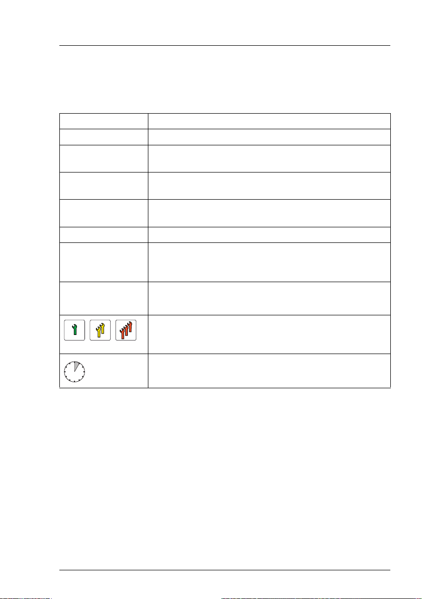
2.1 Classification of procedures . . . . . . . . . . . . . . . . . 23
2.1.1 Customer Replaceable Units (CRU) . . . . . . . . . . . . . . . 23
2.1.2 Upgrade and Repair Units (URU) . . . . . . . . . . . . . . . . 24
2.1.3 Field Replaceable Units (FRU) . . . . . . . . . . . . . . . . . 25
2.2 Average task duration . . . . . . . . . . . . . . . . . . . . . 26
2.3 Tools you need at hand . . . . . . . . . . . . . . . . . . . . 27
2.4 Documents you need at hand . . . . . . . . . . . . . . . . . 28
3 Important information . . . . . . . . . . . . . . . . . . . . . 31
3.1 Safety instructions . . . . . . . . . . . . . . . . . . . . . . . 31
3.2 ENERGY STAR . . . . . . . . . . . . . . . . . . . . . . . . . 39
3.3 CE conformity . . . . . . . . . . . . . . . . . . . . . . . . . 42
3.4 FCC Class A Compliance Statement . . . . . . . . . . . . . 43
3.5 Environmental protection . . . . . . . . . . . . . . . . . . . 44
4 Basic hardware procedures . . . . . . . . . . . . . . . . . . 47
4.1 Using diagnostics information . . . . . . . . . . . . . . . . 47
4.2 Opening the server . . . . . . . . . . . . . . . . . . . . . . . 48
4.2.1 Shutting down the server . . . . . . . . . . . . . . . . . . . . 48
4.2.2 Removing the server cover . . . . . . . . . . . . . . . . . . . 51
MX130 S2 Upgrade and Maintenance Manual 5
Page 6

Contents
4.3 Opening the front cage . . . . . . . . . . . . . . . . . . . . . 52
4.4 Closing the front cage . . . . . . . . . . . . . . . . . . . . . . 53
4.5 Closing the server . . . . . . . . . . . . . . . . . . . . . . . . 54
4.5.1 Mounting the server cover . . . . . . . . . . . . . . . . . . . . 54
4.5.2 Connecting the server to the mains . . . . . . . . . . . . . . . . 55
4.6 Switching on the server . . . . . . . . . . . . . . . . . . . . . 58
5 Basic software procedures . . . . . . . . . . . . . . . . . . . 59
5.1 Starting the maintenance task . . . . . . . . . . . . . . . . . 59
5.1.1 Disabling BitLocker functionality . . . . . . . . . . . . . . . . . 59
5.1.2 Removing backup and optical disk media . . . . . . . . . . . . 60
5.1.3 Verifying and configuring the backup software solution . . . . . . 61
5.2 Completing the maintenance task . . . . . . . . . . . . . . . 62
5.2.1 Updating the system board BIOS . . . . . . . . . . . . . . . . . 62
5.2.2 Updating RAID controller firmware . . . . . . . . . . . . . . . . 63
5.2.3 Enabling Option ROM scan . . . . . . . . . . . . . . . . . . . . 64
5.2.4 Verifying and configuring the backup software solution . . . . . . 64
5.2.5 Viewing the System Event Log (SEL) . . . . . . . . . . . . . . . 65
5.2.6 Enabling BitLocker functionality . . . . . . . . . . . . . . . . . . 66
5.2.7 Performing a RAID array rebuild . . . . . . . . . . . . . . . . . 67
5.2.8 Looking up changed MAC addresses . . . . . . . . . . . . . . . 67
5.2.9 Using the Chassis ID Prom Tool . . . . . . . . . . . . . . . . . 68
6 Power supply . . . . . . . . . . . . . . . . . . . . . . . . . . 69
6.1 Standard PSU . . . . . . . . . . . . . . . . . . . . . . . . . . 70
6.1.1 Replacing the standard PSU . . . . . . . . . . . . . . . . . . . 70
6.1.1.1 Required tools . . . . . . . . . . . . . . . . . . . . . . . . . 70
6.1.1.2 Preliminary steps . . . . . . . . . . . . . . . . . . . . . . . 70
6.1.1.3 Disconnecting internal power cables . . . . . . . . . . . . . 71
6.1.1.4 Removing the PSU . . . . . . . . . . . . . . . . . . . . . . 72
6.1.1.5 Installing the PSU . . . . . . . . . . . . . . . . . . . . . . . 73
6.1.1.6 Reconnecting internal power cables . . . . . . . . . . . . . 76
6.1.1.7 Concluding steps . . . . . . . . . . . . . . . . . . . . . . . 77
6 Upgrade and Maintenance Manual MX130 S2
Page 7

Contents
7 HDDs and accessible drives . . . . . . . . . . . . . . . . . . 79
7.1 Basic procedure . . . . . . . . . . . . . . . . . . . . . . . . 81
7.2 Mounting order . . . . . . . . . . . . . . . . . . . . . . . . . 82
7.3 Installing 3.5-inch HDD in HDD1 / HDD2 chassis bay . . . . 83
7.3.1 Required tools . . . . . . . . . . . . . . . . . . . . . . . . . . 83
7.3.2 Preliminary steps . . . . . . . . . . . . . . . . . . . . . . . . 83
7.3.3 Installing a 3.5-inch HDD in HDD 1/HDD 2 chassis bay . . . . . 84
7.3.4 Concluding steps . . . . . . . . . . . . . . . . . . . . . . . . 87
7.4 Removing 3.5-inch HDD out of HDD1 / HDD2 chassis bay . 88
7.4.1 Required tools . . . . . . . . . . . . . . . . . . . . . . . . . . 88
7.4.2 Preliminary steps . . . . . . . . . . . . . . . . . . . . . . . . 88
7.4.3 Removing a 3.5-inch HDD out of HDD 1/HDD 2 chassis bay . . 89
7.4.4 Concluding steps . . . . . . . . . . . . . . . . . . . . . . . . 91
7.5 Installing additional 3.5-inch HDD in 3.5-inch chassis bay . 91
7.5.1 Required tools . . . . . . . . . . . . . . . . . . . . . . . . . . 91
7.5.2 Preliminary steps . . . . . . . . . . . . . . . . . . . . . . . . 91
7.5.3 Installing an additional 3.5-inch HDD in 3.5-inch chassis bay . . 92
7.5.4 Concluding steps . . . . . . . . . . . . . . . . . . . . . . . . 93
7.6 Removing additional 3.5-inch HDD out of
3.5-inch chassis bay . . . . . . . . . . . . . . . . . . . . . . 94
7.6.1 Required tools . . . . . . . . . . . . . . . . . . . . . . . . . . 94
7.6.2 Preliminary steps . . . . . . . . . . . . . . . . . . . . . . . . 94
7.6.3 Removing an additional 3.5-inch HDD out of 3.5-inch chassis bay .
95
7.6.4 Concluding steps . . . . . . . . . . . . . . . . . . . . . . . . 96
7.7 Installing additional 3.5-inch HDD in
5.25-inch dummy cover . . . . . . . . . . . . . . . . . . . . 97
7.7.1 Required tools . . . . . . . . . . . . . . . . . . . . . . . . . . 97
7.7.2 Preliminary steps . . . . . . . . . . . . . . . . . . . . . . . . 97
7.7.3 Installing a 3.5-inch HDD in 5.25-inch dummy cover . . . . . . 98
7.7.4 Concluding steps . . . . . . . . . . . . . . . . . . . . . . . . 100
7.8 Removing 3.5-inch HDD out of
5.25-inch dummy cover . . . . . . . . . . . . . . . . . . . . 100
7.8.1 Required tools . . . . . . . . . . . . . . . . . . . . . . . . . . 100
7.8.2 Preliminary steps . . . . . . . . . . . . . . . . . . . . . . . . 100
7.8.3 Removing a 3.5-inch HDD out of 5.25-inch dummy cover . . . . 101
7.8.4 Concluding steps . . . . . . . . . . . . . . . . . . . . . . . . 103
MX130 S2 Upgrade and Maintenance Manual 7
Page 8

Contents
7.9 Installing additional 3.5-inch HDD in 5.25-inch ODD/HDD
bracket . . . . . . . . . . . . . . . . . . . . . . . . . . . . . 103
7.9.1 Required tools . . . . . . . . . . . . . . . . . . . . . . . . . 103
7.9.2 Preliminary steps . . . . . . . . . . . . . . . . . . . . . . . . 103
7.9.3 Installing an additional 3.5-inch HDD in ODD/HDD bracket . . 104
7.9.4 Concluding steps . . . . . . . . . . . . . . . . . . . . . . . . 106
7.10 Removing 3.5-inch HDD out of 5.25-inch
ODD/HDD bracket . . . . . . . . . . . . . . . . . . . . . . . 106
7.10.1 Required tools . . . . . . . . . . . . . . . . . . . . . . . . . 106
7.10.2 Preliminary steps . . . . . . . . . . . . . . . . . . . . . . . . 107
7.10.3 Removing an additional 3.5-inch HDD out of the
5.25-inch ODD/HDD bracket . . . . . . . . . . . . . . . . . . 107
7.10.4 Concluding steps . . . . . . . . . . . . . . . . . . . . . . . . 110
7.11 Installing 5.25-inch dummy cover . . . . . . . . . . . . . . 110
7.11.1 Required tools . . . . . . . . . . . . . . . . . . . . . . . . . 110
7.11.2 Preliminary steps . . . . . . . . . . . . . . . . . . . . . . . . 110
7.11.3 Installing a 5.25-inch dummy cover . . . . . . . . . . . . . . . 111
7.11.4 Concluding steps . . . . . . . . . . . . . . . . . . . . . . . . 112
7.12 Removing 5.25-inch dummy cover . . . . . . . . . . . . . . 112
7.12.1 Required tools . . . . . . . . . . . . . . . . . . . . . . . . . 112
7.12.2 Preliminary steps . . . . . . . . . . . . . . . . . . . . . . . . 112
7.12.3 Removing a 5.25-inch dummy cover . . . . . . . . . . . . . . 113
7.12.4 Concluding steps . . . . . . . . . . . . . . . . . . . . . . . . 114
7.13 Installing ODD in 5.25-inch chassis bay . . . . . . . . . . . 115
7.13.1 Required tools . . . . . . . . . . . . . . . . . . . . . . . . . 115
7.13.2 Preliminary steps . . . . . . . . . . . . . . . . . . . . . . . . 115
7.13.3 Installing an ODD in 5.25-inch chassis bay . . . . . . . . . . . 116
7.13.4 Concluding steps . . . . . . . . . . . . . . . . . . . . . . . . 117
7.14 Removing ODD out of 5.25-inch chassis bay . . . . . . . . 118
7.14.1 Required tools . . . . . . . . . . . . . . . . . . . . . . . . . 118
7.14.2 Preliminary steps . . . . . . . . . . . . . . . . . . . . . . . . 118
7.14.3 Removing an ODD out of 5.25-inch chassis bay . . . . . . . . 119
7.14.4 Concluding steps . . . . . . . . . . . . . . . . . . . . . . . . 120
7.15 Installing slimline ODD in 5.25-inch ODD/HDD bracket . . . 121
7.15.1 Required tools . . . . . . . . . . . . . . . . . . . . . . . . . 121
7.15.2 Preliminary steps . . . . . . . . . . . . . . . . . . . . . . . . 121
7.15.3 Installing a slimline ODD in 5.25-inch ODD/HDD bracket . . . 122
7.15.4 Concluding steps . . . . . . . . . . . . . . . . . . . . . . . . 124
8 Upgrade and Maintenance Manual MX130 S2
Page 9

Contents
7.16 Removing slimline ODD out of 5.25-inch
ODD/HDD bracket . . . . . . . . . . . . . . . . . . . . . . . 125
7.16.1 Required tools . . . . . . . . . . . . . . . . . . . . . . . . . . 125
7.16.2 Preliminary steps . . . . . . . . . . . . . . . . . . . . . . . . 125
7.16.3 Removing a slimline ODD out of 5.25-inch ODD/HDD bracket . 126
7.16.4 Concluding steps . . . . . . . . . . . . . . . . . . . . . . . . 129
7.17 Installing backup drive in 5.25-inch chassis bay . . . . . . . 130
7.17.1 Required tools . . . . . . . . . . . . . . . . . . . . . . . . . . 130
7.17.2 Preliminary steps . . . . . . . . . . . . . . . . . . . . . . . . 130
7.17.3 Installing a backup drive in 5.25-inch chassis bay . . . . . . . . 131
7.17.4 Concluding steps . . . . . . . . . . . . . . . . . . . . . . . . 132
7.18 Removing backup drive out of 5.25-inch chassis bay . . . . 133
7.18.1 Required tools . . . . . . . . . . . . . . . . . . . . . . . . . . 133
7.18.2 Preliminary steps . . . . . . . . . . . . . . . . . . . . . . . . 133
7.18.3 Removing backup drive out of 5.25-inch chassis bay . . . . . . 134
7.18.4 Concluding steps . . . . . . . . . . . . . . . . . . . . . . . . 135
7.19 Installing slimline ODD in slimline chassis bay . . . . . . . 136
7.19.1 Required tools . . . . . . . . . . . . . . . . . . . . . . . . . . 136
7.19.2 Preliminary steps . . . . . . . . . . . . . . . . . . . . . . . . 136
7.19.3 Removing the ODD filler cover . . . . . . . . . . . . . . . . . 137
7.19.4 Installing the ODD . . . . . . . . . . . . . . . . . . . . . . . . 138
7.19.5 Concluding steps . . . . . . . . . . . . . . . . . . . . . . . . 141
7.20 Replacing slimline ODD out of slimline chassis bay . . . . 142
7.20.1 Required tools . . . . . . . . . . . . . . . . . . . . . . . . . . 142
7.20.2 Preliminary steps . . . . . . . . . . . . . . . . . . . . . . . . 142
7.20.3 Replacing a slimline ODD out of slimline chassis bay . . . . . . 143
7.20.4 Concluding steps . . . . . . . . . . . . . . . . . . . . . . . . 144
8 System fan . . . . . . . . . . . . . . . . . . . . . . . . . . . 145
8.1 Replacing the system fan module . . . . . . . . . . . . . . . 146
8.1.1 Required tools . . . . . . . . . . . . . . . . . . . . . . . . . . 146
8.1.2 Preliminary steps . . . . . . . . . . . . . . . . . . . . . . . . 146
8.1.3 Removing the system fan module . . . . . . . . . . . . . . . . 147
8.1.4 Installing the system fan module . . . . . . . . . . . . . . . . 150
8.1.5 Concluding steps . . . . . . . . . . . . . . . . . . . . . . . . 157
MX130 S2 Upgrade and Maintenance Manual 9
Page 10

Contents
9 Expansion cards . . . . . . . . . . . . . . . . . . . . . . . . 159
9.1 Basic procedure . . . . . . . . . . . . . . . . . . . . . . . . 160
9.2 Expansion cards . . . . . . . . . . . . . . . . . . . . . . . . 161
9.2.1 Installing expansion cards . . . . . . . . . . . . . . . . . . . 161
9.2.1.1 Required tools . . . . . . . . . . . . . . . . . . . . . . . . 161
9.2.1.2 Preliminary steps . . . . . . . . . . . . . . . . . . . . . . 161
9.2.1.3 Removing a PCI slot bracket . . . . . . . . . . . . . . . . 162
9.2.1.4 Installing an expansion card . . . . . . . . . . . . . . . . . 163
9.2.1.5 Connecting cables to the expansion card . . . . . . . . . . 165
9.2.1.6 Concluding steps . . . . . . . . . . . . . . . . . . . . . . 165
9.2.2 Removing expansion cards . . . . . . . . . . . . . . . . . . . 165
9.2.2.1 Required tools . . . . . . . . . . . . . . . . . . . . . . . . 165
9.2.2.2 Preliminary steps . . . . . . . . . . . . . . . . . . . . . . 166
9.2.2.3 Removing an expansion card . . . . . . . . . . . . . . . . 166
9.2.2.4 Installing a PCI slot bracket . . . . . . . . . . . . . . . . . 167
9.2.2.5 Concluding steps . . . . . . . . . . . . . . . . . . . . . . 167
9.2.3 Installing eSATA cable . . . . . . . . . . . . . . . . . . . . . 168
9.2.3.1 Required tools . . . . . . . . . . . . . . . . . . . . . . . . 168
9.2.3.2 Preliminary steps . . . . . . . . . . . . . . . . . . . . . . 168
9.2.3.3 Installing an eSATA cable (optional for specific markets) . . 168
9.2.3.4 Connecting cable of the eSATA cable to connector . . . . . 170
9.2.3.5 Concluding steps . . . . . . . . . . . . . . . . . . . . . . 170
9.2.4 Removing eSATA cable . . . . . . . . . . . . . . . . . . . . . 170
9.2.4.1 Required tools . . . . . . . . . . . . . . . . . . . . . . . . 171
9.2.4.2 Preliminary steps . . . . . . . . . . . . . . . . . . . . . . 171
9.2.4.3 Disconnecting eSATA cable (optional for specific markets) . 171
9.2.4.4 Removing an eSATA cable . . . . . . . . . . . . . . . . . 172
9.2.4.5 Concluding steps . . . . . . . . . . . . . . . . . . . . . . 172
9.3 Additional tasks . . . . . . . . . . . . . . . . . . . . . . . . 173
9.3.1 Mounting expansion card slot brackets . . . . . . . . . . . . . 173
9.3.1.1 Required tools . . . . . . . . . . . . . . . . . . . . . . . . 173
9.3.1.2 Network adapter D2907 . . . . . . . . . . . . . . . . . . . 174
9.3.1.3 Network adapter D2745 . . . . . . . . . . . . . . . . . . . 176
10 Main memory . . . . . . . . . . . . . . . . . . . . . . . . . 179
10.1 Basic procedure . . . . . . . . . . . . . . . . . . . . . . . . 180
10.1.1 Memory sequence . . . . . . . . . . . . . . . . . . . . . . . 180
10.1.2 Operation modes . . . . . . . . . . . . . . . . . . . . . . . . 181
10 Upgrade and Maintenance Manual MX130 S2
Page 11

Contents
10.2 Installing memory modules . . . . . . . . . . . . . . . . . . 182
10.2.1 Required tools . . . . . . . . . . . . . . . . . . . . . . . . . . 182
10.2.2 Preliminary steps . . . . . . . . . . . . . . . . . . . . . . . . 182
10.2.3 Installing a memory module . . . . . . . . . . . . . . . . . . . 182
10.2.4 Concluding steps . . . . . . . . . . . . . . . . . . . . . . . . 183
10.3 Removing memory modules . . . . . . . . . . . . . . . . . . 184
10.3.1 Required tools . . . . . . . . . . . . . . . . . . . . . . . . . . 184
10.3.2 Preliminary steps . . . . . . . . . . . . . . . . . . . . . . . . 184
10.3.3 Removing a memory module . . . . . . . . . . . . . . . . . . 184
10.3.4 Concluding steps . . . . . . . . . . . . . . . . . . . . . . . . 185
11 Processors . . . . . . . . . . . . . . . . . . . . . . . . . . . 187
11.1 Basic procedure . . . . . . . . . . . . . . . . . . . . . . . . 188
11.2 Replacing the processor heat sink . . . . . . . . . . . . . . 188
11.2.1 Required tools . . . . . . . . . . . . . . . . . . . . . . . . . . 188
11.2.2 Preliminary steps . . . . . . . . . . . . . . . . . . . . . . . . 188
11.2.3 Removing the processor heat sink . . . . . . . . . . . . . . . 189
11.2.4 Thermal paste . . . . . . . . . . . . . . . . . . . . . . . . . . 190
11.2.5 Installing the processor heat sink . . . . . . . . . . . . . . . . 190
11.2.6 Concluding steps . . . . . . . . . . . . . . . . . . . . . . . . 191
11.3 Replacing the processor . . . . . . . . . . . . . . . . . . . . 191
11.3.1 Required tools . . . . . . . . . . . . . . . . . . . . . . . . . . 191
11.3.2 Preliminary steps . . . . . . . . . . . . . . . . . . . . . . . . 192
11.3.3 Removing the processor heat sink . . . . . . . . . . . . . . . 192
11.3.4 Removing the processor . . . . . . . . . . . . . . . . . . . . . 192
11.3.5 Installing the processor . . . . . . . . . . . . . . . . . . . . . 194
11.3.6 Applying thermal paste . . . . . . . . . . . . . . . . . . . . . 196
11.3.7 Installing the processor heat sink . . . . . . . . . . . . . . . . 197
11.3.8 Concluding steps . . . . . . . . . . . . . . . . . . . . . . . . 197
12 System board and components . . . . . . . . . . . . . . . . 199
12.1 Replacing the CMOS battery . . . . . . . . . . . . . . . . . 200
12.1.1 Required tools . . . . . . . . . . . . . . . . . . . . . . . . . . 200
12.1.2 Preliminary steps . . . . . . . . . . . . . . . . . . . . . . . . 201
12.1.3 Removing the CMOS battery . . . . . . . . . . . . . . . . . . 201
12.1.4 Installing the CMOS battery . . . . . . . . . . . . . . . . . . . 202
12.1.5 Concluding steps . . . . . . . . . . . . . . . . . . . . . . . . 203
MX130 S2 Upgrade and Maintenance Manual 11
Page 12

Contents
12.2 Trusted Platform Module (TPM) . . . . . . . . . . . . . . . . 204
12.2.1 Installing the TPM board . . . . . . . . . . . . . . . . . . . . 204
12.2.1.1 Required tools . . . . . . . . . . . . . . . . . . . . . . . . 204
12.2.1.2 Preliminary steps . . . . . . . . . . . . . . . . . . . . . . 204
12.2.1.3 Installing the TPM board . . . . . . . . . . . . . . . . . . 205
12.2.1.4 Concluding steps . . . . . . . . . . . . . . . . . . . . . . 208
12.2.2 Removing the TPM board . . . . . . . . . . . . . . . . . . . . 209
12.2.2.1 Required tools . . . . . . . . . . . . . . . . . . . . . . . . 209
12.2.2.2 Preliminary steps . . . . . . . . . . . . . . . . . . . . . . 210
12.2.2.3 Removing the TPM board . . . . . . . . . . . . . . . . . . 211
12.2.2.4 Concluding steps . . . . . . . . . . . . . . . . . . . . . . 212
12.3 Replacing the system board . . . . . . . . . . . . . . . . . 213
12.3.1 Required tools . . . . . . . . . . . . . . . . . . . . . . . . . 213
12.3.2 Preliminary steps . . . . . . . . . . . . . . . . . . . . . . . . 214
12.3.3 Removing the system board . . . . . . . . . . . . . . . . . . 215
12.3.4 Installing the system board . . . . . . . . . . . . . . . . . . . 218
12.3.4.1 Mounting the system board . . . . . . . . . . . . . . . . . 218
12.3.5 Concluding steps . . . . . . . . . . . . . . . . . . . . . . . . 221
13 Front panel and front USB . . . . . . . . . . . . . . . . . . 223
13.1 Replacing the front panel indicators . . . . . . . . . . . . 224
13.1.1 Required tools . . . . . . . . . . . . . . . . . . . . . . . . . 224
13.1.2 Preliminary steps . . . . . . . . . . . . . . . . . . . . . . . . 224
13.1.3 Removing the On/Off button . . . . . . . . . . . . . . . . . . 225
13.1.4 Removing the HDD activity LED . . . . . . . . . . . . . . . . 226
13.1.5 Removing the cable for On/Off button and HDD activity LED . 227
13.1.6 Installing the On/Off button and the HDD activity LED . . . . . 228
13.1.7 Concluding steps . . . . . . . . . . . . . . . . . . . . . . . . 228
13.2 Replacing the front USB board . . . . . . . . . . . . . . . . 229
13.2.1 Required tools . . . . . . . . . . . . . . . . . . . . . . . . . 229
13.2.2 Preliminary steps . . . . . . . . . . . . . . . . . . . . . . . . 229
13.2.3 Removing the defective front USB board . . . . . . . . . . . . 230
13.2.4 Installing the new front USB board . . . . . . . . . . . . . . . 231
13.2.5 Concluding steps . . . . . . . . . . . . . . . . . . . . . . . . 232
14 Cables . . . . . . . . . . . . . . . . . . . . . . . . . . . . . 233
14.1 Cabling overview . . . . . . . . . . . . . . . . . . . . . . . 234
12 Upgrade and Maintenance Manual MX130 S2
Page 13

Contents
14.1.1 Overview of used cables . . . . . . . . . . . . . . . . . . . . . 234
14.2 Cabling . . . . . . . . . . . . . . . . . . . . . . . . . . . . . 235
14.2.1 Power cabling . . . . . . . . . . . . . . . . . . . . . . . . . . 235
14.2.2 Data cabling . . . . . . . . . . . . . . . . . . . . . . . . . . . 237
14.3 Replacing the power cable . . . . . . . . . . . . . . . . . . 239
14.3.1 Required tools . . . . . . . . . . . . . . . . . . . . . . . . . . 239
14.3.2 Preliminary steps . . . . . . . . . . . . . . . . . . . . . . . . 239
14.3.3 Removing the power cable . . . . . . . . . . . . . . . . . . . 240
14.3.4 Installing the power cable . . . . . . . . . . . . . . . . . . . . 242
14.3.5 Concluding steps . . . . . . . . . . . . . . . . . . . . . . . . 243
15 Appendix . . . . . . . . . . . . . . . . . . . . . . . . . . . . 245
15.1 Mechanical overview . . . . . . . . . . . . . . . . . . . . . . 245
15.1.1 Server front . . . . . . . . . . . . . . . . . . . . . . . . . . . 245
15.1.2 Server rear . . . . . . . . . . . . . . . . . . . . . . . . . . . . 246
15.1.3 Server interior . . . . . . . . . . . . . . . . . . . . . . . . . . 247
15.2 Configuration tables . . . . . . . . . . . . . . . . . . . . . . 248
15.2.1 Mounting order for HDDs . . . . . . . . . . . . . . . . . . . . 248
15.2.2 Memory board configuration . . . . . . . . . . . . . . . . . . . 248
15.2.3 Expansion card configuration table . . . . . . . . . . . . . . . 248
15.3 Connectors and indicators . . . . . . . . . . . . . . . . . . 249
15.3.1 Connectors and indicators on the system board . . . . . . . . 249
15.3.1.1 Onboard connectors . . . . . . . . . . . . . . . . . . . . . 249
15.3.1.2 Onboard settings . . . . . . . . . . . . . . . . . . . . . . . 250
15.3.1.3 I/O panel connectors . . . . . . . . . . . . . . . . . . . . . 251
15.3.1.4 I/O panel indicators . . . . . . . . . . . . . . . . . . . . . . 252
15.3.2 Connectors and indicators on the front panel . . . . . . . . . . 253
15.4 Minimum startup configuration . . . . . . . . . . . . . . . . 254
MX130 S2 Upgrade and Maintenance Manual 13
Page 14

Contents
14 Upgrade and Maintenance Manual MX130 S2
Page 15

Version history
Issue number Reason for update
Initial release
MX130 S2 Upgrade and Maintenance Manual 15
Page 16

V
ersion history
16 Upgrade and Maintenance Manual MX130 S2
Page 17

1 Introduction
This Upgrade and Maintenance Manual provides instructions for the following
procedures:
● Upgrading the server configuration by adding optional hardware
components
● Upgrading the server configuration by replacing existing hardware
components with superior ones.
● Replacing defective hardware components
V CAUTION!
The document at hand comprises procedures of a wide range of
complexity. Check the profile of qualification for technicians before
assigning tasks. Before you start, carefully read "Classification of
procedures" on page 23.
MX130 S2 Upgrade and Maintenance Manual 17
Page 18

Introduction
1.1 Where to find which information?
While the Upgrade and Maintenance Manual focuses on upgrade and
maintenance procedures to bring the server back to normal operation,
additional manuals provide detailed background information on server
components and BIOS settings.
For information on documents you need to have with you when leaving for
maintaining a server see "Documents you need at hand" on page 28.
I PRIMERGY manuals are available in PDF format on the
ServerView Suite DVD 2. The ServerView Suite DVD 2 is part of the
ServerView Suite supplied with every server.
If you no longer have the ServerView Suite DVDs, you can obtain the
relevant current versions using the order number U15000-C289 (the
order number for the Japanese market: please refer to the configurator
of the server http://primeserver.fujitsu.com/primergy/system/).
The PDF files of the manuals can also be downloaded free of charge
from the Internet. The overview page showing the online documentation
available on the Internet can be found using the URL (for EMEA market):
http://manuals.ts.fujitsu.com. The PRIMERGY server documentation can
be accessed using the Industry standard servers navigation option.
For the Japanese market:
Please refer to the following URL for the latest product manuals:
http://primeserver.fujitsu.com/primergy/manual/
Before using the product, please check for additional information that
may be available under the following URL:
http://primeserver.fujitsu.com/primergy/products/note/
18 Upgrade and Maintenance Manual MX130 S2
Page 19
Introduction
1.2 Notational conventions
The following notational conventions are used in this manual:
Text in italics indicates commands or menu items
fixed font indicates system output
semi-bold fixed
font
"Quotation marks" indicate names of chapters and terms that are being
Ê describes activities that must be performed in the order
[Abc] indicates keys on the keyboard
indicates text to be entered by the user
emphasized
shown
V CAUTION! Pay particular attention to texts marked with this symbol!
Failure to observe this warning may endanger your life,
destroy the system or lead to the loss of data.
I indicates additional information, notes and tips
indicates the procedure category in terms of complexity
and qualification requirements, see "Classification of
procedures" on page 23
indicates the average task duration, see "Average task
duration" on page 26
MX130 S2 Upgrade and Maintenance Manual 19
Page 20

Introduction
20 Upgrade and Maintenance Manual MX130 S2
Page 21

2 Before you start
Before you start any upgrade or maintenance task, please proceed as follows:
Ê Carefully read the safety instructions in chapter "Important information" on
page 31.
Ê Make sure that all necessary manuals are available. Refer to the
documentation overview in section "Documents you need at hand" on
page 28. Print the PDF files if required.
Ê Make yourself familiar with the procedure categories introduced in section
"Classification of procedures" on page 23.
Ê Ensure that all required tools are available according to section "Tools you
need at hand" on page 27.
Installing optional components
The "PRIMERGY MX130 S2 Server Operating manual" gives an introduction to
server features and provides an overview of available hardware options.
Use the Fujitsu ServerView Suite management software to prepare hardware
expansions. ServerView Suite documentation is available online at
http://manuals.ts.fujitsu.com (http://primeserver.fujitsu.com/primergy/system/ (for the
Japanese market) or from the ServerView Suite DVD 2 supplied with your
PRIMERGY server. Please refer to the following ServerView Suite topics:
– Operation
– Virtualization
– Maintenance
I For the latest information on hardware options, refer to your server’s
hardware configurator available online at the following address:
for the EMEA market:
http://ts.fujitsu.com/products/standard_servers/micro_server/primergy_mx130
s2x.html
for the Japanese market:
http://primeserver.fujitsu.com/primergy/system/
MX130 S2 Upgrade and Maintenance Manual 21
Page 22

Before you start
Please contact your local Fujitsu customer service partner for details on how to
order expansion kits or spare parts. Use the Fujitsu Illustrated Spares Catalog
to identify the required spare part and obtain technical data and order
information. Illustrated Spares catalogs are available online at
http://manuals.ts.fujitsu.com/illustrated_spares (EMEA market only).
22 Upgrade and Maintenance Manual MX130 S2
Page 23
Before you start
2.1 Classification of procedures
The complexity of maintenance procedures varies significantly. Procedures
have been assigned to one of three unit categories, indicating the level of
difficulty and required qualification.
At the beginning of each procedure, the involved unit type is indicated by one of
the symbols introduced in this section.
I Please ask your local Fujitsu service center for more detailed
information.
2.1.1 Customer Replaceable Units (CRU)
Customer Replaceable Units (CRU)
Non hot-plug peripherals that are handled as Customer Replaceable Units
– Keyboard
– Mouse
MX130 S2 Upgrade and Maintenance Manual 23
Page 24

Before you start
2.1.2 Upgrade and Repair Units (URU)
Upgrade and Repair Units (URU)
Upgrade and Repair Units are non hot-plug components that can be ordered
separately to be installed as options (Upgrade Units).
Upgrade and repair procedures involve shutting down and opening the server.
V CAUTION!
The device may be seriously damaged or cause damage if it is opened
without authorization or if repairs are attempted by unauthorized and
untrained personnel.
Components that are handled as Upgrade Units
– Processors (upgrade kits)
– ODDs
– Backup drives
– Expansion cards
– Memory modules
– Non hot-plug HDDs
Components that are handled solely as Repair Units
– CMOS battery
– Non hot-plug fans
24 Upgrade and Maintenance Manual MX130 S2
Page 25

Before you start
2.1.3 Field Replaceable Units (FRU)
Field Replaceable Units (FRU)
Removing and installing Field Replaceable Units involves complex maintenance
procedures on integral server components. Procedures will require shutting
down, opening and disassembling the server.
V CAUTION!
Maintenance procedures involving Field Replaceable Units must be
performed exclusively by Fujitsu service personnel or technicians trained
by Fujitsu. Please note that unauthorized interference with the system
will void the warranty and exempt the manufacturer from all liability.
Components that are handled as Field Replaceable Units
– Processors (replacements)
– Front panel (the On/Off button and the HDD activity LED)
– System board
– Standard PSU
– Trusted Platform Module (TPM)
I Please ask your local Fujitsu service center for more detailed
information.
MX130 S2 Upgrade and Maintenance Manual 25
Page 26
Before you start
2.2 Average task duration
Average task duration: 10 minutes
The average task duration including preliminary and concluding steps is
indicated at the beginning of each procedure next to the procedure class.
Refer to table 1 on page 26 for an overview of steps taken into account for
calculating the average task duration:
Step included Explanation
Shutdown time depends on hardware and
Server shutdown no
Disassembly yes making the server available
Transport no
Maintenance
procedures
Transport no
Assembly yes reassembling the server
Starting up no
Table 1: Calculation of the average task duration
yes
software configuration and may vary
significantly.
Transporting the server to the service table
(where required) depends on local
customer conditions.
maintenance procedures including
preliminary and concluding software tasks
Returning the server to its installation site
(where required) depends on local
customer conditions.
Booting time depends on hardware and
software configuration and may vary
significantly.
26 Upgrade and Maintenance Manual MX130 S2
Page 27
Before you start
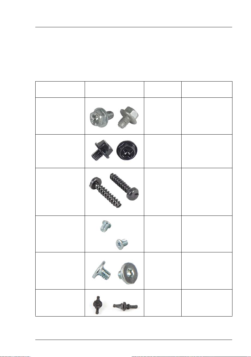
2.3 Tools you need at hand
When preparing the maintenance task, ensure that all required tools are
available according to the overview below. You will find a list of required tools at
the beginning of each procedure.
Screw driver /
Bit insert
Phillips
PH2 / (+) No. 2
hexagonal cross
SW5 / PZ2
Phillips
PH2 / (+) No. 2
hexagonal cross
SW5 / PZ2
TPM bit insert
Dedicated TPM
screw driver /
TPM module
fixing tool (for the
Japanese market)
Phillips
PH1
Torx Plus Size 6
Philips (+) No.00
silver
For EMEA: Torx
For Japan: Philips
Front Fan Rivets
Pincer / Side
cutter
Screw Usage Type
Board,
M3 x 4.5 mm
(silver)
Front USB
C26192-Y10-C67
UNC
HDD3, HDD4
TPM screw
One way
head
(black)
2.5 HDD
(on request
only)
slimline ODD
in additional
5.25 inch
bracket
System fan C26361-K690-C3
6-32 x 4.76 mm
(black)
C26192-Y10-C75
REM 3 x 15 mm
(black)
C26192-Y10C176
M3x 3.5 / 0.25 Nm
(silver)
C26192-Y10C102
M 2.0 x 2.5 /
0.2 Nm
C26192-Y10C163
Table 2: List of required tools and used screws
MX130 S2 Upgrade and Maintenance Manual 27
Page 28

Before you start
2.4 Documents you need at hand
Maintenance procedures may include references to additional documentation.
When preparing the maintenance task, ensure that all required manuals are
available according to the overview below.
I – Ensure to store all printed manuals enclosed with your server in a
save place for future reference.
– Unless stated otherwise, all manuals are available online at
http://manuals.ts.fujitsu.com under Industry standard servers or from the
ServerView Suite DVD 2 supplied with your PRIMERGY server.
For the Japanese market please use the following address:
http://primeserver.fujitsu.com/primergy/manual/.
Document Description
"Quick Start Hardware" Quick installation poster
"PRIMERGY ServerView Suite Overview & Installation" DVD
booklet
"Safety notes and regulations"
manual
" 安全上のご注意 " for the
Japanese market
"PRIMERGY MX130 S2 Server
Operating Manual"
"
Short Description - Mainboard
D3090 / D3091
"Description - BIOS Manual
D3090 / D3091"
Software documentation
Table 3: Documentation you need at hand
"
DVD booklet on initial software
configuration included as a printed copy
with the ServerView Suite
Important safety information, available from
the ServerView Suite DVD 2, online at
http://manuals.ts.fujitsu.com and as a printed
copy
available from the ServerView Suite DVD 2
or online at http://manuals.ts.fujitsu.com
Information on system board features,
layout, connectors and indicators, available
from the ServerView Suite DVD 2 or online
at http://manuals.ts.fujitsu.com
Information on configurable BIOS options
and parameters, available from the
ServerView Suite DVD 2 or online at
http://manuals.ts.fujitsu.com
– "ServerView Operations Manager -
Server Management" user guide
28 Upgrade and Maintenance Manual MX130 S2
Page 29
Document Description
Glossary
available from the ServerView Suite DVD 2
or online at http://manuals.ts.fujitsu.com
Important information on warranty
"Warranty" manual
" 保証書 " for the Japanese
market
regulations, recycling and service, available
from the ServerView Suite DVD 2, online at
http://manuals.ts.fujitsu.com or as a printed
copy
"Returning used devices"
manual
"Service Desk" leaflet
" サポート&サービス " for the
Recycling and contact information,
available from the ServerView Suite DVD 2,
online at http://manuals.ts.fujitsu.com or as a
printed copy
Japanese market
– Operating system documentation,
Third party documentation
online help
– Peripherals documentation
Table 3: Documentation you need at hand
Before you start
MX130 S2 Upgrade and Maintenance Manual 29
Page 30

Before you start
30 Upgrade and Maintenance Manual MX130 S2
Page 31

3 Important information
V CAUTION!
Before installing and starting up a device, please observe the safety
instructions listed in the following section. This will help you to avoid
making serious errors that could impair your health, damage the device
and endanger the data base.
I Keep all manual and the other documentation (such as the technical
manual, documentation DVD) close to the device. All documentation
must be included if the equipment is passed on to a third party.
3.1 Safety instructions
I The following safety instructions are also provided in the manual "Safety
Notes and Regulations" or " 安全上のご注意 ".
This device meets the relevant safety regulations for IT equipment. If you have
any questions about whether you can install the server in the intended
environment, please contact your sales outlet or our customer service team.
● The actions described in this manual shall be performed by technical
specialists. A technical specialist is a person who is trained to install the
server including hardware and software.
● Repairs to the device that do not relate to CSS failures shall be performed
by service personnel. Please note that unauthorized interference with the
system will void the warranty and exempt the manufacturer from all liability.
● Any failure to observe the guidelines in this manual, and any improper
repairs could expose the user to risks (electric shock, energy hazards, fire
hazards) or damage the equipment.
● Before installing/removing internal options to/from the server, turn off the
server, all peripheral devices, and any other connected devices. Also unplug
all power cords from the power outlet. Failure to do so can cause electric
shock or damage.
Before starting up
● During installation and before operating the device, observe the instructions
on environmental conditions for your device.
MX130 S2 Upgrade and Maintenance Manual 31
Page 32

Important information
● If the device is brought in from a cold environment, condensation may form
both inside and on the outside of the device.
Wait until the device has acclimatized to room temperature and is absolutely
dry before starting it up. Material damage may be caused to the device if this
requirement is not observed.
● Transport the device only in the original packaging or in packaging that
protects it from knocks and jolts.
For the Japanese market, transporting the device in its original packaging
does not apply.
Installation and operation
● This unit should not be operated in ambient temperatures above 35 °C.
● If the unit is integrated into an installation that draws power from an industrial
power supply network with an IEC309 connector, the power supply's fuse
protection must comply with the requirements for non-industrial power
supply networks for type A connectors.
● The unit automatically adjusts itself to a mains voltage in a range of 100 V -
240 V. Ensure that the local mains voltage lies within these limits.
● This device must only be connected to properly grounded power outlets or
connected to the grounded rack internal power distribution system with
tested and approved power cords.
● Ensure that the device is connected to a properly grounded power outlet
close to the device.
● Ensure that the power sockets on the device and the properly grounded
power outlets are easily accessible.
● The On/Off button or the main power switch (if present) does not isolate the
device from the mains power supply. In case of repair or servicing
disconnect the device completely from the mains power supply, unplug all
power plugs from the properly grounded power outlets.
● Always connect the server and the attached peripherals to the same power
circuit. Otherwise you run the risk of losing data if, for example, the server is
still running but a peripheral device (e.g. memory subsystem) fails during a
power outage.
● Data cables must be adequately shielded.
32 Upgrade and Maintenance Manual MX130 S2
Page 33

Important information
● Ethernet cabling has to comply with EN 50173 and EN 50174-1/2 standards
or ISO/IEC 11801 standard respectively. The minimum requirement is a
Category 5 shielded cable for 10/100 Ethernet, or a Category 5e cable for
Gigabit Ethernet.
● Route the cables in such a way that they do not create a potential hazard
(make sure no-one can trip over them) and that they cannot be damaged.
When connecting the server, refer to the relevant instructions in this manual.
● Never connect or disconnect data transmission lines during a storm (risk of
lightning hazard).
● Make sure that no objects (e.g. jewelry, paperclips etc.) or liquids can get
inside the server (risk of electric shock, short circuit).
● In emergencies (e.g. damaged casing, controls or cables, penetration of
liquids or foreign bodies), contact the system administrator or your customer
service team. Only disconnect the system from the mains power supply if
there is no risk of harming yourself.
● Proper operation of the system (in accordance with IEC 60950-1 resp.
EN 60950-1) is only ensured if the casing is completely assembled and the
rear covers for the installation slots have been fitted (electric shock, cooling,
fire protection, interference suppression).
● Only install system expansions that satisfy the requirements and rules
governing safety and electromagnetic compatibility and those relating to
telecommunication terminals. If you install other expansions, they may
damage the system or violate the safety regulations. Information on which
system expansions are approved for installation can be obtained from our
customer service center or your sales outlet.
● The components marked with a warning notice (e.g. lightning symbol) may
only be opened, removed or exchanged by authorized, qualified personnel.
Exception: CSS components can be replaced.
● The warranty is void if the server is damaged during installation or
replacement of system expansions.
● Only set screen resolutions and refresh rates that are specified in the
operating manual for the monitor. Otherwise, you may damage your monitor.
If you are in any doubt, contact your sales outlet or customer service center.
● Before installing/removing internal options to/from the server, turn off the
server, all peripheral devices, and any other connected devices. Also unplug
all power cords from the outlet. Failure to do so can cause electric shock.
MX130 S2 Upgrade and Maintenance Manual 33
Page 34

Important information
● Do not damage or modify internal cables or devices. Doing so may cause a
device failure, fire, or electric shock and will void the warranty and exempt
the manufacturer from all liability.
● Devices inside the server remain hot after shutdown. Wait for a while after
shutdown before installing or removing internal options.
● The circuit boards and soldered parts of internal options are exposed and
can be damaged by static electricity. To ensure reliable protection, if you are
wearing an earthing band on your wrist when working with this type of
module, connect it to an unpainted, non-conducting metal part of the system.
● Do not touch the circuitry on boards or soldered parts. Hold the metallic
areas or the edges of the circuit boards.
● Install the screw removed during installation/detaching internal options in
former device/position. To use a screw of the different kind can cause a
breakdown of equipment.
● The installation indicated on this document is sometimes changed to the
kind of possible options without notice.
34 Upgrade and Maintenance Manual MX130 S2
Page 35

Important information
Batteries
● Incorrect replacement of batteries may lead to a risk of explosion. The
batteries may only be replaced with identical batteries or with a type
recommended by the manufacturer.
● Do not throw batteries into the trash can.
● Batteries must be disposed of in accordance with local regulations
concerning special waste.
● Make sure that you insert the battery the right way round.
● The battery used in this device may present a fire or chemical burn hazard
if mistreated. Do not disassemble, heat about 100 °C (212F), or incinerate
the battery.
● All batteries containing pollutants are marked with a symbol (a crossed-out
garbage can). In addition, the marking is provided with the chemical symbol
of the heavy metal decisive for the classification as a pollutant:
Cd Cadmium
Hg Mercury
Pb Lead
Working with ODDs and media
When working with ODDs, these instructions must be followed.
V CAUTION!
● Only use CDs/DVDs/BDs that are in perfect condition, in order to
prevent data loss, equipment damage and injury.
● Check each CD/DVD/BD for damage, cracks, breakages etc. before
inserting it in the drive.
Note that any additional labels applied may change the mechanical
properties of a CD/DVD/BD and cause imbalance and vibrations.
Damaged and imbalanced CDs/DVDs/BDs can break at high drive
speeds (data loss).
Under certain circumstances, sharp CD/DVD/BD fragments can
pierce the cover of the ODD (equipment damage) and can fly out of
the device (danger of injury, particularly to uncovered body parts such
as the face or neck).
MX130 S2 Upgrade and Maintenance Manual 35
Page 36

Important information
● High humidity and airborne dust levels are to be avoided. Electric
shocks and/or server failures may be caused by liquids such as
water, or metallic items, such as paper clips, entering a drive.
● Shocks and vibrations are also to be avoided.
● Do not insert any objects other than the specified CDs/DVDs/BDs.
● Do not pull on, press hard, or otherwise handle the CD/DVD/BD tray
roughly.
● Do not disassemble the ODD.
● Before use, clean the optical disk tray using a soft, dry cloth.
● As a precaution, remove disks from the ODD when the drive is not to
be used for a long time. Keep the optical disk tray closed to prevent
foreign matter, such as dust, from entering the ODD.
● Hold CDs/DVDs/BDs by their edges to avoid contact with the disk
surface.
● Do not contaminate the CD/DVD/BD surface with fingerprints, oil,
dust, etc. If dirty, clean with a soft, dry cloth, wiping from the center to
the edge. Do not use benzene, thinners, water, record sprays,
antistatic agents, or silicone-impregnated cloth.
● Be careful not to damage the CD/DVD/BD surface.
● Keep the CDs/DVDs/BDs away from heat sources.
● Do not bend or place heavy objects on CDs/DVDs/BDs.
● Do not write with ballpoint pen or pencil on the label (printed) side.
● When a CD/DVD/BD is moved from a cold place to a warm place,
moisture condensation on the CD/DVD/BD surface can cause data
read errors. In this case, wipe the CD/DVD/BD with a soft, dry cloth
then let it air dry. Do not dry the CD/DVD/BD using devices such as a
hair dryer.
● To avoid dust, damage, and deformation, keep the CD/DVD/BD in its
case whenever it is not in use.
● Do not store CDs/DVDs/BDs at high temperatures. Areas exposed to
prolonged direct sunlight or near heating appliances are to be
avoided.
36 Upgrade and Maintenance Manual MX130 S2
Page 37

Important information
I You can prevent damage from the ODD and the CDs/DVDs/BDs, as well
as premature wear of the disks, by observing the following suggestions:
– Only insert disks in the drive when needed and remove them after
use.
– Store the disks in suitable sleeves.
– Protect the disks from exposure to heat and direct sunlight.
Laser information
The ODD complies with IEC 60825-1 laser class 1.
V CAUTION!
The ODD contains a light-emitting diode (LED), which under certain
circumstances produces a laser beam stronger than laser class 1.
Looking directly at this beam is dangerous.
Never remove parts of the ODD casing!
Modules with Electrostatic-Sensitive Devices
Modules with electrostatic-sensitive devices are identified by the following
sticker:
Figure 1: ESD label
When you handle components fitted with ESDs, you must always observe the
following points:
● Switch off the system and remove the power plugs from the power outlets
before installing or removing components with ESDs.
● The circuit boards and soldered parts of internal options are exposed and
can be damaged by static electricity. To ensure reliable protection, you must
wear an earthing band on your wrist when working with this type of module
and connect it to an unpainted, non-conducting metal part of the system.
MX130 S2 Upgrade and Maintenance Manual 37
Page 38

Important information
● Any devices or tools that are used must be free of electrostatic charge.
● Wear a suitable grounding cable that connects you to the external chassis
of the system unit.
● Always hold components with ESDs at the edges or at the points marked
green (touch points).
● Do not touch any connectors or conduction paths on an ESD.
● Place all the components on a pad which is free of electrostatic charge.
I For a detailed description of how to handle ESD components, see the
relevant European or international standards (EN 61340-5-1,
ANSI/ESD S20.20).
Transporting the server
● Only transport the server in its original packaging or in packaging that
protects it from impacts and jolts.
For the Japanese market, transporting the device in its original packaging
does not apply.
● Do not unpack the server until it is at its installation location.
38 Upgrade and Maintenance Manual MX130 S2
Page 39

Important information
3.2 ENERGY STAR
I Energy Star is applicable only for 230 V mains voltage.
ENERGY STAR does not apply to the Japanese market.
In typical configurations the PRIMERGY MX130 S2 satisfies the
stringent requirements of the Ecolabel Energy Star for
Computers Version 5.0. These requirements ensure energy
savings when computers are being used and performing a range
of tasks, as well as when they are turned off or into a low power
mode. For example, the power consumption of the PRIMERGY
MX130 S2 in the operation mode “idle” is less than 65 W.
Products that have been certified compliant with ENERGY STAR
and identified as such are in full compliance with the specification
at shipping. Note that energy consumption can be affected by
software that is installed or any changes that are made to the
BIOS or energy options subsequently. In such cases, the
properties guaranteed by ENERGY STAR can no longer be
assured.
Devices that are certified in accordance with ENERGY STAR
environmental standards help to save money and reduce
greenhouse gas emissions.
Detailed information concerning the requirements for the
ENERGY STAR eco-label, as well as products that satisfy these
requirements, can be found on the Internet at
http://www.energystar.gov/ .
After you have installed your OS you can configure the energy
saving settings by yourself (amongst others switch off the
monitor ≤ 15 minutes). How you have to configure these energy
saving settings is described in the documentation supplied with
the OS.
The "ServerView Operations Manager" user guide contains
instructions for reading out measurement values, including those
relating to current energy consumption and air temperatures.
Either the Performance Monitor or the Task Manager can be
used to read out CPU utilization levels.
MX130 S2 Upgrade and Maintenance Manual 39
Page 40

Important information
The system has a hibernate mode (S4 mode) from which it can be woken up via
WOL (Wake-up On LAN). In order to use this feature, however, the S4 mode
must be activated/enabled in the corresponding operating system installed.
The following description is an example and can only serve as a guide for other
operating systems.
To bring your system into S4 mode (= hibernate mode), proceed as follows:
Operating system Microsoft Windows 2008 Enterprise Edition
Activation
Ê Open the command line tool using C:\Windows\System32\cmd.exe and
enter the following command to activate S4 mode:
powercfg -h ON
Configuration
To set the driver for the internal LAN controller:
Ê Open the Device Manager via Start - Control Panel - System - Device Manager.
Ê Select Network Adapters.
Ê Select the internal LAN controller: Broadcom Netlink™ Gigabit Ethernet.
Ê Select Properties in the overview, and then select Power Management.
Ê In the Wake on LAN field, enable the following option:
– Allow this device to wake the server.
Ê Press OK.
Execution
To execute the power down command in a DOS shell:
Using the shutdown -h command, your system saves all user data (e.g: open
windows and running programs), shuts down the system, and transfers it to S4
mode.
40 Upgrade and Maintenance Manual MX130 S2
Page 41

Important information
Exiting the hibernate/idle state (S4 mode)
You switch on the system again either manually using the On/Off button or using
the WOL function (WOL= Wake-up On LAN).
To do this, a Magic Packet with the MAC address of the system to be woken up
is sent to the internal LAN controller.
You will find the valid MAC address for your device in the BIOS:
Ê During boot press [F2] to enter BIOS.
Ê Navigate to Main - System Information and press [Enter].
The MAC address is shown under Network Controller Details.
I Alternatively, you can find out the MAC address valid for your device
using the command line tool IPCONFIG.
Ê Open the command line tool using C:\Windows\System32\cmd.exe
and enter the following command:
ipconfig /all
LINUX operating systems
Activation
Ê To activate S4 mode, enter the following command:
resume=/dev/sdxx
Using this command, the memory area in which the data is saved is
assigned at the same time.
Execution
Using the following command, the system is switched off and brought into S4
mode:
echo -n "disk" > /sys/power/state
Exiting the hibernate/idle state (S4 mode)
You switch on the system again either manually using the On/Off button or using
the WOL function (WOL= Wake-up On LAN).
To do this, a Magic Packet with the MAC address of the system to be woken up
is sent to the internal LAN controller.
MX130 S2 Upgrade and Maintenance Manual 41
Page 42

Important information
3.3 CE conformity
The system complies with the requirements of the EC directives
2004/108/EC regarding "Electromagnetic Compatibility" and
2006/95/EC "Low Voltage Directive". This is indicated by the CE
marking (CE = Communauté Européenne).
42 Upgrade and Maintenance Manual MX130 S2
Page 43

Important information
3.4 FCC Class A Compliance Statement
If there is an FCC statement on the device, it applies to the products covered in
this manual, unless otherwise specified herein. The statement for other
products will appear in the accompanying documentation.
NOTE:
This equipment has been tested and found to comply with the limits for a
"Class A" digital device, pursuant to Part 15 of the FCC rules and meets all
requirements of the Canadian Interference-Causing Equipment Standard
ICES-003 for digital apparatus. These limits are designed to provide reasonable
protection against harmful interference in a residential installation. This
equipment generates, uses and can radiate radio frequency energy and, if not
installed and used in strict accordance with the instructions, may cause harmful
interference to radio communications. However, there is no warranty that
interference will not occur in a particular installation. If this equipment does
cause harmful interference to radio or television reception, which can be
determined by turning the equipment off and on, the user is encouraged to try
to correct the interference by one or more of the following measures:
● Reorient or relocate the receiving antenna.
● Increase the separation between equipment and the receiver.
● Connect the equipment into an outlet on a circuit different from that to which
the receiver is connected.
● Consult the dealer or an experienced radio/TV technician for help.
Fujitsu is not responsible for any radio or television interference caused by
unauthorized modifications of this equipment or the substitution or attachment
of connecting cables and equipment other than those specified by Fujitsu. The
correction of interferences caused by such unauthorized modification,
substitution or attachment will be the responsibility of the user.
The use of shielded I/O cables is required when connecting this equipment to
any and all optional peripheral or host devices. Failure to do so may violate FCC
and ICES rules.
WARNING:
This is a class A product. In a domestic environment this product may cause
radio interference in which case the user may be required to take adequate
measures.
MX130 S2 Upgrade and Maintenance Manual 43
Page 44

Important information
3.5 Environmental protection
Environmentally-friendly product design and development
This product has been designed in accordance with the Fujitsu standard for
"environmentally friendly product design and development". This means that
key factors such as durability, selection and labeling of materials, emissions,
packaging, ease of dismantling and recycling have been taken into account.
This saves resources and thus reduces the harm done to the environment.
Further information can be found at:
– http://ts.fujitsu.com/products/standard_servers/index.html (for the EMEA market)
– http://primeserver.fujitsu.com/primergy/concept/ (for the Japanese market)
Energy-saving information
Devices that do not need to be constantly switched on should be switched off
until they are needed as well as during long breaks and after completion of work.
Packaging information
This packaging information doesn’t apply to the Japanese market.
Do not throw away the packaging. You may need it later for transporting the
system. If possible, the equipment should only be transported in its original
packaging.
Information on handling consumables
Please dispose of printer consumables and batteries in accordance with the
applicable national regulations.
In accordance with EU directives, batteries must not be disposed of with
unsorted domestic waste. They can be returned free of charge to the
manufacturer, dealer or an authorized agent for recycling or disposal.
All batteries containing pollutants are marked with a symbol (a crossed-out
garbage can). They are also marked with the chemical symbol for the heavy
metal that causes them to be categorized as containing pollutants:
Cd Cadmium
Hg Mercury
Pb Lead
44 Upgrade and Maintenance Manual MX130 S2
Page 45

Important information
Labels on plastic casing parts
Please avoid sticking your own labels on plastic parts wherever possible, since
this makes it difficult to recycle them.
Returns, recycling and disposal
Please handle returns, recycling and disposal in accordance with local
regulations.
The device must not be disposed of with domestic waste. This
device is labeled in compliance with European directive
2002/96/EC on waste electrical and electronic equipment (WEEE).
This directive sets the framework for returning and recycling used
equipment and is valid across the EU. When returning your used
device, please use the return and collection systems available to
you. Further information can be found at
http://ts.fujitsu.com/recycling.
Details regarding the return and recycling of devices and consumables within
Europe can also be found in the "Returning used devices" manual, via your local
Fujitsu branch or from our recycling center in Paderborn:
Fujitsu Technology Solutions
Recycling Center
D-33106 Paderborn
Tel. +49 5251 525 1410
Fax +49 5251 525 32 1410
MX130 S2 Upgrade and Maintenance Manual 45
Page 46

Important information
46 Upgrade and Maintenance Manual MX130 S2
Page 47

4 Basic hardware procedures
4.1 Using diagnostics information
The "PRIMERGY MX130 S2 Server Operating manual" gives an introduction to
server features and provides an overview of available hardware options.
Use the Fujitsu ServerView Suite management software to plan the upgrade or
replacement of hardware components. ServerView Suite documentation is
available online at http://manuals.ts.fujitsu.com or from the ServerView Suite
DVD 2 supplied with your PRIMERGY server. Please refer to the following
ServerView Suite topics:
– Operation
– Maintenance
MX130 S2 Upgrade and Maintenance Manual 47
Page 48

Basic hardware procedures
4.2 Opening the server
V CAUTION!
● Before removing or installing covers, turn off the server and all
peripheral devices. Also unplug all power cables from the outlet.
Failure to do so can cause electric shock.
● In order to comply with applicable EMC regulations (regulations on
electromagnetic compatibility) and satisfy cooling requirements, the
PRIMERGY MX130 S2 server must not run while the server cover is
removed.
● For further safety information, please refer to chapter "Important
information" on page 31.
4.2.1 Shutting down the server
V CAUTION!
For further safety information, please refer to chapter "Important
information" on page 31.
I This step is only required when upgrading or replacing non-hot plug
components.
Ê Inform the system administrator that the server will be shut down and put
offline.
Ê Terminate all applications.
Ê Verify if your backup software solution requires preparative configuration
before starting the procedure as described in section "Verifying and
configuring the backup software solution" on page 61.
Ê Remove all backup and optical disk media from backup and optical disk
drives as described in section "Removing backup and optical disk media" on
page 60.
48 Upgrade and Maintenance Manual MX130 S2
Page 49

Basic hardware procedures
/
Figure 2: Power button on the front panel
Ê Shut down the server.
I If the system is running an ACPI-compliant operating system,
pressing the On / Off button will perform a graceful shutdown.
Disconnecting power cords
Figure 3: Removing the power cord from the PSU
Ê Disconnect the power cord from the PSU module.
MX130 S2 Upgrade and Maintenance Manual 49
Page 50

Basic hardware procedures
Only for Japan: Disconnecting cable tie
Figure 4: Removing the cable tie
Ê Pull out on the locking lever on the PSU cable tie (1) and loosen the
loope (2).
Ê Disconnect the power cord from the PSU module and remove it from the
cable tie.
50 Upgrade and Maintenance Manual MX130 S2
Page 51

Basic hardware procedures
4.2.2 Removing the server cover
Figure 5: Unlocking the locking bar
Ê Slide the locking bar to the left until it rests in place.
Figure 6: Removing the server cover
Ê Push the server cover to the front.
Ê Remove the server cover.
MX130 S2 Upgrade and Maintenance Manual 51
Page 52

Basic hardware procedures
4.3 Opening the front cage
Figure 7: Opening the front cage
Ê Carefully fold open the front cage.
I Pay attention to the SATA data cable, especially to the the slimline ODD
SATA data cable when you fold open the front cage. If it is located in the
additional 5.25-inch bracket, you have to disconnect the SATA data cable
from the drive before fold open the front cage.
52 Upgrade and Maintenance Manual MX130 S2
Page 53

4.4 Closing the front cage
Figure 8: Closing the front cage
Basic hardware procedures
Ê Carefully close the front cage.
V CAUTION!
Ensure that none of the cables are strained or trapped!
Ê If you loosened any cables tighten them again.
MX130 S2 Upgrade and Maintenance Manual 53
Page 54

Basic hardware procedures
4.5 Closing the server
V CAUTION!
● Before attaching the covers, make sure no unnecessary parts or tools
are left inside the server.
● In order to comply with applicable EMC regulations (regulations on
electromagnetic compatibility) and satisfy cooling requirements, the
PRIMERGY MX130 S2 server must not run while the server cover is
removed.
● For further safety information, please refer to chapter "Important
information" on page 31.
4.5.1 Mounting the server cover
Figure 9: Mounting the server cover
Ê Fit the server cover on the chassis.
54 Upgrade and Maintenance Manual MX130 S2
Page 55

Basic hardware procedures
Figure 10: Closing the server cover
Ê Slide the server cover shut by engaging the locking mechanism.
4.5.2 Connecting the server to the mains
The PRIMERGY MX130 S2 Server is equipped with a standard PSU.
V CAUTION!
The power supply automatically adjusts to any mains voltage in the
range of 100 V - 240 V. You may only operate the server if its rated
voltage range corresponds to the local mains voltage.
Ê Connect the insulated connector of the power cable to the PSU of the server.
Ê Connect the mains plug to a grounded mains outlet in the in-house power
supply network.
MX130 S2 Upgrade and Maintenance Manual 55
Page 56

Basic hardware procedures
Connecting power cord
Figure 11: Connecting power cord
Ê Connect the power cord to the power supply.
56 Upgrade and Maintenance Manual MX130 S2
Page 57

Basic hardware procedures
Only for Japan: Connecting the cable tie
Figure 12: Connecting the cable tie
Ê Thread the cable tie through the eye (1).
Ê Pull the cable tie tight to secure the power cord (2).
The insulated connector cannot now be disconnected from the server
accidentally.
MX130 S2 Upgrade and Maintenance Manual 57
Page 58

Basic hardware procedures
4.6 Switching on the server
V CAUTION!
● Before switching on the server, make sure the server cover is closed.
In order to comply with applicable EMC regulations (regulations on
electromagnetic compatibility) and satisfy cooling requirements, the
PRIMERGY MX130 S2 server must not run while the server cover is
removed.
● Follow the safety instructions in chapter "Important information" on
page 31.
Ê Connect all peripheral cables to the rear connector panel of the server.
Ê Connect the power cord as described in section "Connecting the server to
the mains" on page 55.
Ê Connect the power cord to the power outlet.
/
Figure 13: Power button on the front panel
Ê Press the On / Off button to start up the server (1).
Ê Ensure that the power-on indicator in the On / Off button is lit green.
I For more information see "Front panel and front USB" on page 223.
58 Upgrade and Maintenance Manual MX130 S2
Page 59

5 Basic software procedures
5.1 Starting the maintenance task
5.1.1 Disabling BitLocker functionality
BitLocker Drive Encryption provides protection for operating system and data
drives by encrypting the contents and requiring users to authenticate their
credentials to access the information. On the operating system drive, BitLocker
uses the compatible Trusted Platform Module (TPM) to detect if the computer's
startup process has been modified from its original state.
Disabling BitLocker Drive Encryption is a temporary method for removing
BitLocker protection without decrypting the drive Windows is installed on.
Disable BitLocker before modifying the server’s hardware configuration or
startup files. Enable BitLocker again after the maintenance procedure is
complete.
V CAUTION!
– With BitLocker features enabled, modifying the system configuration
(hardware or firmware settings) may render the system inaccessible.
The system may enter Recovery Mode and require a 48-digits
recovery password to return to normal operation.
Ensure to disable BitLocker drive encryption before maintaining the
server.
– When disabled, BitLocker uses a plain text key instead of the Trusted
Platform Module (TPM) to read encrypted files. Keep in mind that
information on this drive is not secure until BitLocker has been reenabled.
Ê Ask the system administrator to disable BitLocker-protection on the
operating system drive, using the BitLocker setup wizard available either
from the Control Panel or Windows Explorer:
Ê Open Bitlocker Drive Encryption by clicking the Start button, clicking
Control Panel, clicking Security, and then clicking Bitlocker Drive
Encryption.
MX130 S2 Upgrade and Maintenance Manual 59
Page 60

Basic software procedures
I Administrator permission required: If you are prompted for an
administrator password or confirmation, type the password or
provide confirmation.
Ê To temporarily disable BitLocker, click Turn Off BitLocker, and then click
Disable BitLocker Drive Encryption.
I In order to determine which features are accessible through the
BitLocker setup wizard, modify the BitLocker Group Policy settings.
For further information on how to disable BitLocker drive encryption,
please refer to the Microsoft Knowledge Base.
Fujitsu service partners will find additional information (also available
in Japanese) on the Fujitsu Extranet web pages.
5.1.2 Removing backup and optical disk media
Ê Ask the system administrator to eject all remaining backup or optical media
from the backup or optical disk drive before removing it from the server.
Ê If the backup media cannot be ejected by conventional means, and it is
mandatory that the cartridge be removed prior to returning the drive for
repair or disposing it, a manual tape extraction needs to be performed.
For further information on "forcible" tape ejection, please refer to the "Tape
Facts" guide available to Fujitsu service partners from the following https
address:
https://partners.ts.fujitsu.com/com/service/ps/Servers/PRIMERGY/Pages/
TapeFacts.aspx
I Fujitsu does not assume responsibility for any damage to the tape
drive, the data cartridge / tape or for the loss of any data resulting
from manual tape extraction procedures.
60 Upgrade and Maintenance Manual MX130 S2
Page 61

Basic software procedures
5.1.3 Verifying and configuring the backup software solution
I This task only applies to the Japanese market.
Depending on the backup software solution, it may be necessary to disable or
delete the backup drive from the backup software drive list before starting the
maintenance task.
This is the case for the following backup software solution:
– BackupExec
I Procedures may differ depending on the backup software. For details,
refer to the dedicated documentation provided separately.
Further information on suitable backup software solutions and related
documentation is available to Fujitsu service partners from the Fujitsu
Extranet pages.
MX130 S2 Upgrade and Maintenance Manual 61
Page 62

Basic software procedures
5.2 Completing the maintenance task
5.2.1 Updating the system board BIOS
After replacing the system board, it is essential to upgrade the BIOS to the latest
version.
The latest BIOS versions are available from the Fujitsu support internet pages
at:
http://ts.fujitsu.com/support/ (EMEA market)
http://primeserver.fujitsu.com/primergy/downloads/ (Japanese market)
I Fujitsu does not assume responsibility for any damage done to the
server or for the loss of any data resulting from BIOS updates.
BIOS recovery procedure
I For the Japanese market, follow the instructions provided separately.
Ê Prepare a USB stick with the following files:
– Update tool
– Startup.nsh (which will execute the update tool)
– BIOS image file for update (16 MB with header information)
Ê Ensure that the server has been shut down and disconnected from the
mains as described in sections "Shutting down the server" on page 48.
Ê Open the side cover as described in section "Opening the server" on
page 48.
Ê Enter BIOS recovery mode using the onboard jumpers.
I For detailed information on jumper settings, refer to section "Onboard
settings" on page 250.
Ê Close the side cover as described in section "Closing the server" on
page 54.
Ê Connect the USB stick to the USB port.
Ê Connect the server to the mains as described in section "Connecting the
server to the mains" on page 55.
62 Upgrade and Maintenance Manual MX130 S2
Page 63

Basic software procedures
Ê Press the On / Off button to start up the server.
The system will detect the USB stick and the BIOS recovery process will be
performed.
V CAUTION!
Do not interrupt the BIOS upgrade process after it has started. If the
process is interrupted, the system BIOS may be permanently
corrupted.
Ê After completion of the flash process, shut down the server.
Ê Open the side cover as described in section "Closing the server" on
page 54.
Ê Disable BIOS recovery mode using the onboard jumpers:
I For detailed information on jumper settings, refer to section "Onboard
settings" on page 250.
Ê Close the side cover as described in section "Closing the server" on
page 54.
5.2.2 Updating RAID controller firmware
The onboard RAID controller firmware is updated with the system board BIOS.
Please proceed as described in section "Updating the system board BIOS" on
page 62.
MX130 S2 Upgrade and Maintenance Manual 63
Page 64

Basic software procedures
5.2.3 Enabling Option ROM scan
In order to configure an expansion card that has been installed or replaced, the
card’s Option ROM has to be enabled in the system board BIOS. The card’s
firmware is called by the system BIOS upon reboot and can be entered and
configured.
Option ROM can be enabled permanently (e.g. in case of a boot controller that
may require frequent setup) or temporarily for one-time configuration.
When the enabled expansion card is initialized during the POST phase of the
boot sequence, a key combination is displayed temporarily to enter the
expansion card’s firmware.
Ê Press the displayed key combination.
Ê Modify the expansion card firmware options as desired.
Ê Save your changes and exit the firmware.
As default setting for this system, Option ROM is enabled for all onboard
controllers and all expansion card slots.
For detailed information on how to access the BIOS and modify settings, refer
to the "D3090/D3091 BIOS Manual".
5.2.4 Verifying and configuring the backup software solution
I This task only applies to the Japanese market.
Disabling backup drives
Depending on the backup software solution, it may be necessary to disable or
delete the backup drive from the backup software drive list and reconfigure
backup jobs after completing the maintenance task.
This is the case for the following backup software solutions:
– Netvault for Windows
–ARCServe
– BackupExec
64 Upgrade and Maintenance Manual MX130 S2
Page 65

Basic software procedures
I Procedures may differ depending on the backup software. For details,
refer to the dedicated documentation provided separately.
Further information on suitable backup software solutions and related
documentation is available to Fujitsu service partners from the Fujitsu
Extranet pages.
Re-enabling backup drives
If a backup drive has been disabled or deleted from the backup software drive
list as described in section 5.1.3 on page 61, it has to be re-enabled to complete
the maintenance task.
Ê Re-enable backup drives and revise backup software settings and cronjobs.
I Detailed information on suitable backup software solutions and
related documentation is available to Fujitsu service partners from the
Fujitsu Extranet pages
5.2.5 Viewing the System Event Log (SEL)
You can view the System Event Log (SEL) using the ServerView Operations
Manager:
Ê In ServerView Operations Manager Single System View select Maintenance
from the Information / Operation menu.
Ê Under Maintenance select System Event Log.
Ê Select the message type(s) you want to display:
– Critical events
– Major events
– Minor events
– Informational events
I For detailed information on how to view and sort the SEL using
ServerView Operations Manager, refer to the "ServerView Operations
Manager - Server Management" user guide.
MX130 S2 Upgrade and Maintenance Manual 65
Page 66

Basic software procedures
5.2.6 Enabling BitLocker functionality
If BitLocker Drive Encryption has been disabled for maintenance purposes (see
section "Disabling BitLocker functionality" on page 59), it has to be re-enabled
to complete the service task.
I If BitLocker Drive Encryption has been disabled prior to replacing
components you won't be asked for a recovery key when rebooting the
server after the maintenance task. However, if BitLocker functionality has
not been disabled, Windows will enter recovery mode and ask you to
input recovery key for further booting.
Ê In this case, ask the system administrator to enter the recovery key in
order to boot the operating system.
Ê Ask the system administrator to enable BitLocker-protection on the
operating system drive, using the BitLocker setup wizard available either
from the Control Panel or Windows Explorer.
Ê Open Bitlocker Drive Encryption by clicking the Start button, clicking
Control Panel, clicking Security, and then clicking Bitlocker Drive
Encryption.
I Administrator permission required: If you are prompted for an
administrator password or confirmation, type the password or
provide confirmation.
Ê To enable a temporarily disabled BitLocker, click Turn On BitLocker.
Ê Follow the instructions in the BitLocker Setup wizard.
I For further information on how to enable BitLocker drive encryption,
please refer to the Microsoft Knowledge Base.
Fujitsu service partners will find additional information (also available in
Japanese) on the Fujitsu Extranet web pages.
66 Upgrade and Maintenance Manual MX130 S2
Page 67

Basic software procedures
5.2.7 Performing a RAID array rebuild
After replacing a hard disk drive that has been combined into a RAID array,
RAID rebuild will be performed completely unattended as a background
process.
Figure 14: Progress bar (RAID array rebuild)
V CAUTION!
The system is now operational, however, data redundancy will not be
available until the RAID array rebuild is complete. Depending on the hard
disk drive capacity the overall process can take up to several hours, in
some cases even days.
I You may notice a slight performance impact during rebuild.
5.2.8 Looking up changed MAC addresses
When replacing the system board, the MAC (Media Access Control) address
will change. In order to look up changed MAC adresses, proceed as follows:
Ê Enter the BIOS.
Ê In the Main menu, select System Information and press [Enter].
Ê Note down the new 12-digit MAC address displayed under Network
Controller Details.
Ê Press [Esc] to exit the System Information menu.
Ê Press [Esc] to exit the BIOS.
Ê Inform the customer about the changed MAC address.
MX130 S2 Upgrade and Maintenance Manual 67
Page 68

Basic software procedures
5.2.9 Using the Chassis ID Prom Tool
The Chassis ID EPROM located on the system board contains system
information like server name and model, housing type, serial number and
manufacturing data.
In order to integrate your system into the ServerView management environment
and to enable server installation using the ServerView Installation Manager,
system data needs to be complete and correct.
After replacing the system board, system information has to be entered using
the ChassisID_Prom Tool. The tool and further instructions are available to
maintenance personnel from Fujitsu Technology Solutions Extranet:
https://partners.ts.fujitsu.com/com/service/intelservers/tools
I For the Japanese market, follow the instructions provided separately.
68 Upgrade and Maintenance Manual MX130 S2
Page 69

6 Power supply
Basic information
The PRIMERGY MX130 S2 server is equipped with a standard PSU.
V CAUTION!
The server supports a mains voltage in the range of 100 V - 240 V You
may only operate the server if its rated voltage range corresponds to the
local mains voltage.
Safety notes
V CAUTION!
● Do not disassemble the PSU. Doing so may cause electric shock.
● Areas around the PSU may remain extremely hot after shutdown.
After shutting down the server, wait for hot components to cool down
before removing PSUs.
● The PSU is heavy, so handle it carefully. If you drop it by mistake,
injuries may result.
● For further safety information, please refer to chapter "Important
information" on page 31.
MX130 S2 Upgrade and Maintenance Manual 69
Page 70

Power supply
6.1 Standard PSU
6.1.1 Replacing the standard PSU
Field Replaceable Units (FRU)
Average task duration: 10 minutes
6.1.1.1 Required tools
● Preliminary and concluding steps: tool-less
● Replacing the PSU:
– Phillips PH2 / (+) No. 2 screw driver
6.1.1.2 Preliminary steps
Before replacing the standard PSU, perform the following steps:
I You are advised to perform this routine with the server in a horizontal
position.
Ê Disable BitLocker functionality as described in section "Disabling BitLocker
functionality" on page 59.
Ê Follow all procedures described in section "Opening the server" on page 48.
70 Upgrade and Maintenance Manual MX130 S2
Page 71

6.1.1.3 Disconnecting internal power cables
0
/
Figure 15: Disconnecting internal power cables
Power supply
Ê While pressing the release latch (1) on the connector, disconnect the PSU
ATX power connector from system board connector POWER12V (2)
MX130 S2 Upgrade and Maintenance Manual 71
Page 72

Power supply
6.1.1.4 Removing the PSU
0
/
Figure 16: Removing the PSU
Ê Remove four screws from the PSU (see circles).
Ê Slide the defective PSU inward by 3 cm (1) to disengage the locking
mechanism.
Ê Lift the defective PSU out of the chassis (2).
72 Upgrade and Maintenance Manual MX130 S2
Page 73

6.1.1.5 Installing the PSU
/
Power supply
0
Figure 17: Installing the PSU
MX130 S2 Upgrade and Maintenance Manual 73
Page 74

Power supply
Figure 18: Installing the standard PSU
Ê Insert the PSU into the chassis leaving a gap of about 3 cm to the rear
chassis wall (1) in figure 17.
Ê Ensure that the mounting bracket on the chassis (see circle in figure 18)
engages with the notch on the lower surface of the PSU.
Ê Slide the new PSU towards the rear of the chassis (2) in figure 17.
74 Upgrade and Maintenance Manual MX130 S2
Page 75

Power supply
Figure 19: Securing the PSU
Ê Secure the PSU to the chassis with four screws (M3 x 4.5 mm, see circles).
MX130 S2 Upgrade and Maintenance Manual 75
Page 76

Power supply
6.1.1.6 Reconnecting internal power cables
Figure 20: Connecting internal power cables
Ê Connect the PSU ATX power connector to system board connector
POWER12V.
76 Upgrade and Maintenance Manual MX130 S2
Page 77

Power supply
6.1.1.7 Concluding steps
Perform the following procedures to complete the task:
Ê Follow all procedures described in section "Closing the server" on page 54.
Ê If BitLocker functionality is used and has been disabled before starting the
maintenance task, re-enable BitLocker as described in section "Enabling
BitLocker functionality" on page 66.
MX130 S2 Upgrade and Maintenance Manual 77
Page 78

Power supply
78 Upgrade and Maintenance Manual MX130 S2
Page 79

7 HDDs and accessible drives
Safety notes
V CAUTION!
● The HDDs must all be marked clearly so that they can be put back in
their original places after an upgrade. If this is not done, existing data
can be lost.
● When a HDD is starting up, a resonant noise may be audible for a
short while. This does not indicate a failure.
● Depending on the OS, you can configure the write cache settings for
the HDDs. If a power failure should occur while the write cache is
enabled, cached data may be lost.
● When disposing of, transferring, or returning a hard disk or solid state
drive, wipe out the data on the drive for your own security.
● Rough handling of HDDs may damage the stored data. To cope with
any unexpected problems, always back up important data. When
backing up data to another HDD, you should make backups on a file
or partition basis.
● Handle the device on a shock and vibration free surface.
● Do not use the device in extremely hot or cold locations, or locations
with extreme temperature changes.
● Never attempt to disassemble a hard disk or solid state drive.
● Before removing a HDD, wait for about 30 seconds until the disk has
stopped spinning completely.
● Before installing an accessible drive, acquaint yourself with the
drive's user documentation.
● When inserting an accessible drive into the server, ensure not to
pinch or strain any connected cables.
● When installing an accessible drive, hold it by its sides. Applying force
to the top of the casing may cause failures.
● When disposing of, transferring, or returning a backup drive, ensure
that all backup media has been removed from the drive.
MX130 S2 Upgrade and Maintenance Manual 79
Page 80

HDDs and accessible drives
● Do not touch the circuitry on boards or soldered parts. Hold circuit
boards by their metallic areas or edges.
● Circuit boards and soldered parts of internal options are exposed and
can be damaged by static electricity. Always discharge static build-up
(e.g. by touching a grounded object) before handling electrostaticsensitive devices (ESDs).
● For further safety information, please refer to chapter "Important
information" on page 31.
In this chapter
● "Mounting order" on page 82
– 3.5-inch HDD subsystem
● "Installing 3.5-inch HDD in HDD1 / HDD2 chassis bay" on page 83
● "Removing 3.5-inch HDD out of HDD1 / HDD2 chassis bay" on page 88
● "Installing additional 3.5-inch HDD in 3.5-inch chassis bay" on page 91
● "Removing additional 3.5-inch HDD out of 3.5-inch chassis bay" on page 94
● "Installing additional 3.5-inch HDD in 5.25-inch dummy cover" on page 97
● "Removing 3.5-inch HDD out of 5.25-inch dummy cover" on page 100
● "Installing additional 3.5-inch HDD in 5.25-inch ODD/HDD bracket" on
page 103
● "Removing 3.5-inch HDD out of 5.25-inch ODD/HDD bracket" on page 106
– 2.5-inch HDD subsystem
I2.5-inch SATA HDDs available on project request in EMEA market only.
● "Installing 5.25-inch dummy cover" on page 110
● "Removing 5.25-inch dummy cover" on page 112
● "Installing ODD in 5.25-inch chassis bay" on page 115
● "Removing ODD out of 5.25-inch chassis bay" on page 118
● "Installing slimline ODD in 5.25-inch ODD/HDD bracket" on page 121
● "Removing slimline ODD out of 5.25-inch ODD/HDD bracket" on page 125
80 Upgrade and Maintenance Manual MX130 S2
Page 81

HDDs and accessible drives
● "Installing backup drive in 5.25-inch chassis bay" on page 130
● "Removing backup drive out of 5.25-inch chassis bay" on page 133
● "Installing slimline ODD in slimline chassis bay" on page 136
● "Replacing slimline ODD out of slimline chassis bay" on page 142
7.1 Basic procedure
– HDDs with different capacities are installed from lowest to highest capacity.
– HDDs with different rotation speeds are installed from lowest to highest
speed.
– Please refer to section "Mounting order" on page 82 for a complete overview
of the mounting sequence.
MX130 S2 Upgrade and Maintenance Manual 81
Page 82

HDDs and accessible drives
7.2 Mounting order
Maximum configuration: 4 x 3.5-inch HDD + slimline ODD
Slimline ODD
HDD1
HDD4
HDD2
Figure 21: Slimline ODD mounting order with 4 x 3.5-inch HDD
HDD1
HDD2
Figure 22: Slimline ODD mounting order with 3 x 3.5inch HDD or 2 x 3.5inch HDD and RDX
HDD1
HDD2
HDD3
HDD3 / RDX
Slimline ODD
HH ODD / RDX
HDD3
Figure 23: HH ODD or RDX mounting order with 3 x 3.5-inch HDD
82 Upgrade and Maintenance Manual MX130 S2
Page 83

HDDs and accessible drives
7.3 Installing 3.5-inch HDD in HDD1 / HDD2 chassis bay
Upgrade and Repair Units (URU)
Average task duration: 5 minutes
7.3.1 Required tools
● Preliminary and concluding steps: tool-less
● Installing a 3.5-inch HDD: tool-less
7.3.2 Preliminary steps
Before installing a 3.5-inch HDD, perform the following steps:
Ê Follow all procedures described in section "Opening the server" on page 48.
Ê Open the front cage as described in section "Opening the front cage" on
page 52.
Ê Locate the correct drive bay as described in section "Mounting order" on
page 82.
MX130 S2 Upgrade and Maintenance Manual 83
Page 84

HDDs and accessible drives
7.3.3 Installing a 3.5-inch HDD in HDD 1/HDD 2 chassis bay
Ê Detach and remove the Easy rails from the desired 3.5-inch HDD installation
bay.
Align the three pins on the Easy rails with the screw holes on the new HDD.
Figure 24: Installing the Easy rail on the 3.5-inch HDD
Ê Attach an Easy rail on each side of the new HDD
84 Upgrade and Maintenance Manual MX130 S2
Page 85

Figure 25: Inserting the 3.5-inch HDD
Ê Insert the HDD into its installation bay.
HDDs and accessible drives
MX130 S2 Upgrade and Maintenance Manual 85
Page 86

HDDs and accessible drives
Figure 26: Installing the 3.5-inch HDD
Ê Slide the HDD into its installation bay until the locking latches engage.
86 Upgrade and Maintenance Manual MX130 S2
Page 87

HDDs and accessible drives
1
Figure 27: Connecting the cables
Ê Connect the two SATA connectors to the HDDs (1 and 2).
Ê Plug the cable with the green point to the upper HDD1.
1
/
0
For orientation there is a second green point on the other end of this cable.
Ê Connect the power connectors (3).
7.3.4 Concluding steps
Perform the following procedures to complete the task:
Ê Close the front cage as described in section "Closing the front cage" on
page 53.
Ê Follow all procedures described in section "Closing the server" on page 54.
Ê Please observe the notes on RAID rebuild in section "Performing a RAID
array rebuild" on page 67.
MX130 S2 Upgrade and Maintenance Manual 87
Page 88

HDDs and accessible drives
7.4 Removing 3.5-inch HDD out of HDD1 / HDD2 chassis bay
Upgrade and Repair Units (URU)
Average task duration: 5 minutes
7.4.1 Required tools
● Preliminary and concluding steps: tool-less
● Removing a 3.5-inch HDD: tool-less
7.4.2 Preliminary steps
Before removing a 3.5-inch HDD, perform the following steps:
Ê Ensure that the HDD to be removed is not combined into a RAID array. If the
drive is part of a RAID array, you first need to delete the array using
ServerView RAID Manager.
V CAUTION!
All data on all HDDs in the array will be lost! Be sure to back up your
data before deleting a RAID array.
I For further information, please refer to the "ServerView Suite RAID
Management" user guide, available online at
http://manuals.ts.fujitsu.com or from the ServerView Suite DVD 2
supplied with your PRIMERGY server.
Ê Follow all procedures described in section "Opening the server" on page 48.
Ê Open the front cage as described in section "Opening the front cage" on
page 52.
88 Upgrade and Maintenance Manual MX130 S2
Page 89

HDDs and accessible drives
7.4.3 Removing a 3.5-inch HDD out of HDD 1/HDD 2 chassis bay
0
/
Figure 28: Disconnecting the cables from the a 3.5-inch HDD
Ê Disconnect the power cable (2) and data cable (1).
MX130 S2 Upgrade and Maintenance Manual 89
Page 90

HDDs and accessible drives
/
0
/
Figure 29: Removing a 3.5-inch HDD
Ê Pull the two green handles of the Easy rails in the direction of arrow 1.
Ê Pull the HDD with the two green handles of the Easy rails completely out of
its bay (2).
Figure 30: Inserting the Easy rails
Ê Insert the Easy rails into the bay.
90 Upgrade and Maintenance Manual MX130 S2
Page 91

HDDs and accessible drives
7.4.4 Concluding steps
Perform the following procedures to complete the task:
Ê Close the front cage as described in section "Closing the front cage" on
page 53.
Ê Follow all procedures described in section "Closing the server" on page 54.
7.5 Installing additional 3.5-inch HDD in 3.5inch chassis bay
Upgrade and Repair Units (URU)
Average task duration: 5 minutes
7.5.1 Required tools
● Preliminary and concluding steps: tool-less
● Installing a 3.5-inch HDD
– Phillips PH2 / (+) No. 2 screw driver
7.5.2 Preliminary steps
Before installing a 3.5-inch HDD, perform the following steps:
Ê Follow all procedures described in section "Opening the server" on page 48.
Ê Open the front cage as described in section "Opening the front cage" on
page 52.
Ê Locate the correct drive bay as described in section "Mounting order" on
page 82.
MX130 S2 Upgrade and Maintenance Manual 91
Page 92

HDDs and accessible drives
7.5.3 Installing an additional 3.5-inch HDD in 3.5-inch chassis bay
Figure 31: Installing the HDD in 3.5-inch chassis bay
Ê Insert the HDD into the drive bay and fasten the four screws (see circles).
92 Upgrade and Maintenance Manual MX130 S2
Page 93

HDDs and accessible drives
/
0
Figure 32: Connecting the cables to the HDD
Ê Connect cables to the HDD.
1 Power cable connector P3 (see "Power cable T26139-Y4012-V211"
on page 239)
2 SATA cable T26139-Y4028-V153
7.5.4 Concluding steps
Perform the following procedures to complete the task:
Ê Close the front cage as described in section "Closing the front cage" on
page 53.
Ê Follow all procedures described in section "Closing the server" on page 54.
Ê Please observe the notes on RAID rebuild in section "Performing a RAID
array rebuild" on page 67.
MX130 S2 Upgrade and Maintenance Manual 93
Page 94

HDDs and accessible drives
7.6 Removing additional 3.5-inch HDD out of
3.5-inch chassis bay
7.6.1 Required tools
● Preliminary and concluding steps: tool-less
● Installing a 3.5-inch HDD
– Phillips PH2 / (+) No. 2 screw driver
7.6.2 Preliminary steps
Before installing a 3.5-inch HDD, perform the following steps:
Ê Follow all procedures described in section "Opening the server" on page 48.
Ê Open the front cage as described in section "Opening the front cage" on
page 52.
Ê Locate the correct drive bay as described in section "Mounting order" on
page 82.
94 Upgrade and Maintenance Manual MX130 S2
Page 95

HDDs and accessible drives
7.6.3 Removing an additional 3.5-inch HDD out of 3.5inch chassis bay
/
0
Figure 33: Disconnecting the cables from the HDD
Ê Disonnect cables from the HDD.
1 Power cable connector P3 (see "Power cable T26139-Y4012-V211"
on page 239)
2 SATA cable T26139-Y4028-V153
MX130 S2 Upgrade and Maintenance Manual 95
Page 96

HDDs and accessible drives
Figure 34: Removing the HDD from 3.5-inch chassis bay
Ê Remove the four screws (see circles) and remove the HDD from the drive
bay.
7.6.4 Concluding steps
Perform the following procedures to complete the task:
Ê Close the front cage as described in section "Closing the front cage" on
page 53.
Ê Follow all procedures described in section "Closing the server" on page 54.
96 Upgrade and Maintenance Manual MX130 S2
Page 97

HDDs and accessible drives
7.7 Installing additional 3.5-inch HDD in 5.25inch dummy cover
7.7.1 Required tools
● Preliminary and concluding steps: tool-less
● Installing a 3.5-inch HDD
– Phillips PH2 / (+) No. 2 screw driver
7.7.2 Preliminary steps
Before installing a 3.5-inch HDD, perform the following steps:
Ê Follow all procedures described in section "Opening the server" on page 48.
Ê Locate the correct drive bay as described in section "Mounting order" on
page 82.
Ê Remove the 5.25-inch dummy cover as described in section "Removing a
5.25-inch dummy cover" on page 113.
MX130 S2 Upgrade and Maintenance Manual 97
Page 98

HDDs and accessible drives
7.7.3 Installing a 3.5-inch HDD in 5.25-inch dummy cover
0
/
0
Figure 35: Installing the HDD in the 5.25-inch dummy cover
Ê Insert the HDD into the 5.25-inch dummy cover (1) and fasten the four
screws (2).
Figure 36: Connecting the fixation plate to the 5.25-inch dummy cover
Ê Align the four pins of the fixation plate with the screw holes on the 5.25-inch
dummy cover.
98 Upgrade and Maintenance Manual MX130 S2
Page 99

HDDs and accessible drives
/
Figure 37: Installing the 5.25-inch dummy cover with HDD into the chassis bay
Ê Insert the 5.25-inch dummy cover with HDD in the bay (1) until it snaps into
place.
Ê Open the front cage as described in section "Opening the front cage" on
page 52.
/
Figure 38: Connecting the cables to the HDD
MX130 S2 Upgrade and Maintenance Manual 99
0
Page 100

HDDs and accessible drives
Ê Connect cables to the HDD.
1 Power cable connector P2 (see "Power cable T26139-Y4012-V211"
on page 239)
2 SATA cable T26139-Y4028-V153
7.7.4 Concluding steps
Perform the following procedures to complete the task:
Ê Close the front cage as described in section "Closing the front cage" on
page 53.
Ê Follow all procedures described in section "Closing the server" on page 54.
Ê Please observe the notes on RAID rebuild in section "Performing a RAID
array rebuild" on page 67.
7.8 Removing 3.5-inch HDD out of 5.25-inch dummy cover
7.8.1 Required tools
● Preliminary and concluding steps: tool-less
● Installing a 3.5-inch HDD
– Phillips PH2 / (+) No. 2 screw driver
7.8.2 Preliminary steps
Before removing a 3.5-inch HDD, perform the following steps:
Ê Follow all procedures described in section "Opening the server" on page 48.
Ê Open the front cage as described in section "Opening the front cage" on
page 52.
Ê Locate the correct drive bay as described in section "Mounting order" on
page 82.
100 Upgrade and Maintenance Manual MX130 S2
 Loading...