

Page 1

User’s Manual
For
MVGA-NVG11A
MVGA-NVG11P
MVGA-NVG11AL
MVGA-NVG11AT
MVGA-NVG11PT
MVGA-NVG11AM
MVGA-NVG11AD
DOC NO: 54-0NV11-05 Rev.D
01/02/21
Page 2

I
FCC Requirement
This device has been
certified to comply with the limits for a Class B computing device pursuant to Subpart J of Part 15 of
the FCC Rules. See instructions if interference to radio reception is suspected.
WARNING:
This equipment generates and uses radio frequency energy and,
if not installed or used properly,
that is, in strict accordance with the manufacturer's instructions, may cause interference to radio or
television reception.
It has been tested and found to comply with the limits for a Class B compliant device in acco
rdance with the specifications
in Subpart J of Part 15 of FCC Rules, which are designed to provide reasonable protection against such interference in a
residential installation.
However, there is no guarantee that interference
-will not occur in a particular installation.
If this equipment does cause interference to radio or television reception, which can be determined by turning the
equipment off and on, the user is encouraged to try to correct the interference by one or more of the following measures:
˙
Reorient the receiving antenna
˙
Relocate the computer away from the receiver
˙
Move the computer away from the receiver
˙
Plug the computer into a different outlet so that the computer and the receiver are on different branch
circuits
˙
Ensure that
the card's mounting screws, attachment connector screws, and ground wires are tightly
secured
˙
Ensure that slot covers are installed in all unused slots
If necessary, consult your dealer, service representative, or an experienced radio/television Techn
ician for additional
suggestions.
The manufacturer is not responsible for any radio or TV interference caused by unauthorized modifications to this
equipment. It is the responsibility of the user to correct such interference.
The user may find the following booklet prepared by the Federal Communications Commission helpful:
How to Identify and Resolve Radio-TV Interference Problems.
This booklet is available from the Government Printing Office, Washington, D.C. 20402, Stock No. 004-000-00345-4.
NOTE:
You must use shielded interface cables with a ferrite bead in order to maintain compliance
with the limits for a Class B device.
CAUTION:
CHANGES OR MODIFICATIONS NOT EXPRESSLY APPROVED BY THE PARTY
RESPONSIBLE FOR COMPLIANCE COULD VOID THE USER'S AUTHOR
ITY TO
OPERATE THE EQUIPMENT
Page 3

II
Notice
The information in this document is subject to change in order to improve reliability, design, or function
without prior notice and does not represent a commitment on the part of this company.
In no event will we be liable for direct, indirect, special, incidental, or consequential damages arising out
of the use or the inability to use the product or documentation, even if advised of the possibility of such
damages.
No part of this reference manual may be reproduced or transmitted in any form or by any means without
the prior written permission of this company.
Ó2001
Trademark Acknowledgements
All brand names and trademarks are the property of their owners.
Limited Warranty
Our company warrants this pro
duct against defects in materials and workmanship for a period of one (1)
year from the date of purchase. During the warranty period, a product determined by us to be defective in
form or function will be repaired or at our option, to be replaced at no charge. This warranty does not
apply if the product has been damaged by accident, abuse, misuse, or as a result of service or
modification other than by us.
This warranty is in lieu of any other warranty expressed or implied. In no event shall we be held lia
ble for
incidental or consequential damages, such as lost revenue or lost business opportunities arising from the
purchase of a this product.
Macrovision Corporation Product Notice
This product incorporates copyright protection technology that is prot
ected by method claims of certain
U.S. patents and other intellectual property rights owned by Macrovision Corporation, and other rights
owners. Use of this copyright protection technology must be authorized by Macrovision Corporation, and
is intended for home and other limited viewing uses only unless otherwise authorized by Macrovision
Corporation, Reverse engineering or disassembly is prohibited.
Page 4

III
TABLE OF CONTENTS
1. Introduction
............................................................................................ 1
1.1 Features ............................................................................................................ 1
1.2 System Requirements....................................................................................... 2
1.3 Package Contents ............................................................................................. 2
2. Hardware Installation
............................................................................ 4
2.1 Adapter Configuration...................................................................................... 4
2.2 Installing your VGA adapter ............................................................................ 10
3. Software Installation
.............................................................................. 11
3.1
Installing driver on Windows 98SE/ME
.......................................................... 11
3.2
Installing DirectX on Windows 98SE/ME
....................................................... 11
3.3 View User’s manual ......................................................................................... 12
3.4
Installing driver on Windows 2000
.................................................................. 12
3.5 TV-OUT Function Instructions ........................................................................ 13
3.6 How to change output to Digital Flat Panel?.................................................... 16
3.7
TwinView Function Instructions
...................................................................... 17
4. Display Information ............................................................................... 19
4.1 Resolutions Supported...................................................................................... 19
5. FAQ .......................................................................................................... 20
Page 5

1
1. Introduction
The MVGA-
NVG11A/P/AL/AT/PT/AM/AD is the 3D graphics processors and
multimedia controller. Its innovative architectures combine, transform, and light
technology with a rendering engine that delivers 4 pixels per clock. The nVIDIA
GeForce2 MX not only speed up graphics processing for richer 3D graphics, it also
frees up CPU bandwidth, to the computer systems use, by incorporating GeForce2
MX break-through 3D architecture.
MVGA-
NVG11A/P/AL/AT/PT/AM/AD graphics controller delivers stunning visual
quality and performance, with its 256 bit true-
color engine and 32 bit Z/Stencil
capability.
The MVGA-
NVG11A/P/AL/AT/PT/AM/AD provides outstanding 2D and video
acceleration as well, it 1/2 the power dissipation of GeForce2 MX.
MVGA-
NVG11AT/PT is the o
nly graphics processor able to drive dual digital
displays independently delivering the dual
-head graphics in a single Board. It’s full
supple 2 analog RGB or RGB and DVI.
1.1 Features
□
Integrated second-generation transform and lighting engine.
□
32/64MB memory on board.
□
Integrated true-color 350MHz RAMDAC interface.
□
Supports high screen resolutions up to 2048x1536@75Hz.
□
256-bit 2D and 3D graphics architecture.
□
AGP 4X with Fast Writes.(For MVGA-NVG11A /AL/AT)
□
32-bit color ARGB with destination alpha.
□
Cube environment mapping.
□
Separate hue, saturation, and brightness controls for the video overlay.
□
Video DMA for efficient VIP Host operations.
□
DVD and HDTV- ready motion compensation for MPEG-2 decoding.
□
OpenGL ICD for full OpenGL support.
□
Alternate OS support for OS/2, Linux, and BeOS.
□
Drivers for Windows 2000, Windows 98SE/ME.
□
2.8 GB/second memory bandwidth.
□
20Mtriangles/sec through T&L and setup.
□
nVIDIA shading rasterizer (NSR) Featuring.
□
0.18u technology.
□
Fully support PCI Interface. (Only for MVGA-
NVG11P/PT)
□
Low Profile SPEC (Only for MVGA-
NVG11AM/AD)
Page 6

2
1.2
System Requirements
□
Any motherboard with AGP/PCI bus.
□
Microsoft Windows 98SE / ME / Windows 2000.
□
DirectX 7 and OpenGL Features.
1.3 Package Contents
MVGA-NVG11A
□
MVGA-
NVG11A adapter.
□
Auto-Run Driver CD-Title.
□
User’s Manual.
□
IVI’s WinDVD CD-Title. (Optional)
□
S-
Video Cable 1.8m. (Optional for TV
-OUT)
□
RCA Cable 1.8m. (For TV-OUT)
MVGA-NVG11P
□
MVGA-
NVG11P adapter.
□
Auto-Run Driver CD-Title.
□
User’s Manual.
□
IVI’s WinDVD CD-Title. (Optional)
□
S-
Video Cable 1.8m. (Optional for TV
-OUT)
□
RCA Cable 1.8m. (For TV-OUT)
MVGA-NVG11AL
□
MVGA-
NVG11AL adapter.
□
Auto-Run Driver CD-Title.
□
User’s Manual.
□
IVI’s WinDVD CD-Title. (Optional)
□
S-
Video Cable 1.8m. (Optional for TV
-OUT)
□
RCA Cable 1.8m. (For TV-OUT)
Page 7

3
MVGA-NVG11AT
□
MVGA-
NVG11AT adapter.
□
Auto-Run Driver CD-Title.
□
User’s Manual.
□
IVI’s WinDVD CD-Title. (Optional
)
□
DVI to D-sub connect. (Optional For LCD)
MVGA-NVG11PT
□
MVGA-
NVG11PT adapter.
□
Auto-Run Driver CD-Title.
□
User’s Manual.
□
IVI’s WinDVD CD-Title. (Optional)
□
DVI to D-sub connect. (Optional For LCD)
MVGA-NVG11AM
□
MVGA-
NVG11AM adapter.
□
AutoRun Driver CD-Title.
□
User’s Manual.
□
IVI’s WinDVD CD-Title. (Optional)
□
1 to 2 cable (For TV-OUT)
MVGA-NVG11AD
□
MVGA-
NVG11AD adapter.
□
Auto-Run Driver CD-Title.
□
User’s Manual.
□
IVI’s WinDVD CD-Title. (Optional)
□
S-
Video Cable
1.8m. (Optional for TV-OUT)
□
RCA Cable 1.8m. (For TV-OUT)
□
1 to 2 cable (For TV-OUT)
Page 8

4
2. Hardware Installation
2.1
Adapter Configuration
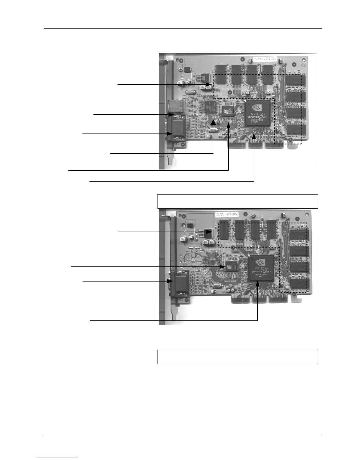
MVGA-NVG11A
MVGA-
NVG11A (w/ TV
-OUT)
MVGA-
NVG11A (w/o TV
-OUT)
32MB SDRAM on board
To monitor
TV-OUT Output
TV-OUT encoder chip
S-
Video Output
BIOS
GeForce2 MX
32MB SDRAM on board
GeForce2 MX
To monitor
BIOS
Page 9

5
MVGA-NVG11P
MVGA-
NVG11P (w/ TV
-OUT)
MVGA-
NVG11P (w/o TV
-OUT)
32MB SDRAM on board
To monitor
TV-OUT encoder chip
PCI Interface
BIOS
GeForce2 MX
TV-OUT Output
S-
Video Output
32MB SDRAM on board
To monitor
PCI Interface
GeForce2 MX
BIOS
Page 10
6
MVGA-NVG11AL
MVGA-
NVG11AL (w/ TV
-OUT)
MVGA-
NVG11AL (w/o TV
-OUT)
64MB SDRAM on board
GeForce2 MX
S-
Video Output
To monitor
TV-OUT encoder chip
BIOS
64MB SDRAM on board
GeForce2 MX
To monitor
BIOS
Page 11

7
MVGA-NVG11AT
MVGA-NVG11AT
MVGA-
NVG11AT (DVI)
32MB SDRAM on board
BIOS
Secondary RCA
Primary RCA
GeForce2 MX
32MB SDRAM on board
To RCA monitor
To LCD monitor
BIOS
GeForce2 MX
Page 12

8
MVGA-NVG11PT
MVGA-
NVG11PT
MVGA-
NVG11PT(DVI)
32MB SDRAM on board
Primary RCA
BIOS
GeForce2 MX
Secondary RCA
32MB SDRAM on board
To RCA monitor
To LCD monitor
BIOS
GeForce2 MX
Page 13
9
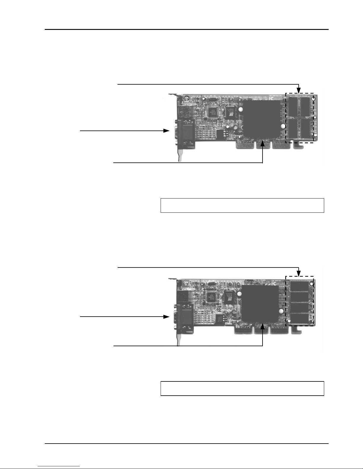
MVGA-NVG11AM
MVGA-
NVG11AM
MVGA-NVG11AD
MVGA-
NVG11AD
32MB SDRAM on board
To monitor
nVIDIA GeForce2 MX
32MB SDRAM on board
To monitor
nVIDIA GeForce2 MX
Page 14

10
2.2 Installing your VGA adapter
1.
Power off your co
mputer, remove its outside cover, and then assert yourself by
touching the power supply of your computer.
Note:
Before installing your new VGA card, you must first set the VGA
option to either Standard VGA or Standard Display VGA.
2.
Remove your old
graphics card, and install your new VGA card into the AGP
slot.
3. Align and secure the mounting bracket of your new VGA card to your computer
and replace your computer cover.
4. Connect your monitor cable to the DB-15 connector at your new VGA card.
5. Power on your computer.
MVGA-
NVG11A
MVGA-
NAG11AL
MVGA-
NVG11AT
MVGA-
NVG11AM
MVGA-
NVG11AD
AGP slot
AGP mainboard
PCI slot
!!! Caution !!!
Before you turn on your system,
you have to be s
ure the VGA card
is setup already and all the cables
are connected.
DO NOT connect / disconnect
TV-out cable when your TV or
PC is Power On.
MVGA-NVG11P
MVGA-
NVG11PT
AGP mainboard
PCI slot
Page 15

11
3. Software Installation
After installing the VGA card in your computer, please turn on your PC, and your
computer will be automatically detected.
3.1 Installing driver on Windows 98SE/ME
Please set the VGA card as ‘
Standard PCI Graphics Adapter (VGA)
’. When asked
if you want to restart your PC, click ‘No’. Then you should follow the next step.
1.
Insert the Auto
-Run CD-ROM driver (wait few seconds). You will see ‘
VGA
Installer’ w
indow that will be shown on the screen. If it does not display, please
browse the CD and double click ‘AutoRun.exe’ icon.
2. Click-on ‘Install Driver’ to install the VGA driver.
3. After the installation is complete, the system will ask you whe
ther you want to
restart your computer now. Click ‘
Yes
’ to reboot your system and activate the
program.
3.2 Installing DirectX on Windows 98SE/ME
When the system restart after finishing the VGA driver setup, please install better
DirectX version than that on your system.
1.
Double click CD-ROM icon to let it auto-run. The ‘VGA Installer’ will be
shown again.
2. Click ‘
Install DirectX’ and you will see a ‘
Installer
’ dialog, and click ‘
OK
’ to
show next page.
3. Click ‘Yes’ to continue.
4. Click-on ‘ReInstall DirectX
’ to install the DirectX program.
5. When it is done, please click ‘OK
’ to reboot Windows.
Page 16

12
3.3 View User's manual
Click ‘User ’s Manual’ to view detailed information regarding the various
Drivers/Programs and FAQ located on the CD.
3.4 Installing driver on Windows 2000
Please set the VGA card as ‘Video Controller (VGA Compatible)’. When asked if
you want to restart your PC, click ‘No’. Then you should follow the next step.
1.
Insert the Auto
-Run CD-ROM driver (wait few seconds). You will see ‘
VGA
Installer
’ window that will be shown on the screen. If it does not display, please
browse the CD and double click ‘AutoRun.exe’ icon.
2. Click ‘Install Driver’ to install the VGA driver.
3. If
you see ‘Digital Signature Not Found’
window, please click
‘Yes’.
4.
When asked if you want to restart your PC, click ‘OK’
to finish the installation
and reboot your Windows.
Page 17

13
3.5 TV-OUT Function Instructions
NOTE:
Before you power on your system, you have to be sure the VGA
card is installed already and all the cables are connected to
prevent form the card get burnt.
3.5.1 How to enable the TV-OUT function
Warning
:
The MVGA-NVG11A/P/
AL/AT/PT needs to see real 75 ohms AV
input. Connect the signal cable between TV-
OUT at VGA card and
TV's Video input, and turn on the TV before launch ‘
Display
Properties
’ window. Otherwise the TV-OUT function would be
gray and un-selectable.
1. Set the correct jumper at your VGA card for TV formats
(PAL BG/NTSC… ).
2. Boot-up the system and display to monitor.
3.
Connect the signal cable between TV-OUT at VGA card and TV’s Video input
and turn on the TV.
4. After launch ‘Display Properties’ window then:
A. Click ‘Settings’ tab
B. Click ‘Advanced… ’
C. Click ‘
Output Device’
tab
D. Select ‘TV’
E. Click ‘Change Format...’
D
A
E
B
C
Page 18

14
3.5.2 How to change TV setting?
1.
You can click ‘TV’ to switch VGA output to
TV.
A. Click ‘
Change TV Format’ to select
which standard TV you want.
When you select ‘Make this format the
power -
up default’; the system will
change BIOS default to the format when
you boot-up it next time.
B. Select ‘
TV resolution and color depth’
to change resolution and color depth.
C. Select ‘
Video output format’ to change
output from Composite Video-Out or
S-Video.
D. Click ‘OK’ to switch your display mode.
Click ‘Yes’ to confirm desktop setting.
Page 19

15
3.5.3 How to adjustment screen position?
1. Click on ‘Display’
icon at Control Panel.
Select ‘Settings’
tab and click ‘Advanced
Pr operties’.
You will see the window.
A.
When the output of your VGA is set to
Monitor, You can click ‘
Device Setting
’
to adjust the screen position
WARNING:
The Monitor display may become
scrambled if you adjust the screen
position over the required range.
Page 20

16
3.6 How to change output to Digital Flat Panel?
1. A.
You can select ‘Digital Flat Panel’ to
switch VGA output to Digital Flat Panel.
B.
Click ‘OK’ or ‘Apply’ to switch your display device.
2. Click ‘OK’ to make sure.
3. Windows 98SE/ME will ask you to keep this
setting. Click ‘Yes’ to finish setting.
Note: The function is only for output device with DVI connector.
Page 21

17
3.7
TwinView Function instructions
3.7.1 Extended Mode
1. A.
You can select ‘Extended Desktop’ to
add second device output of Extended
desktop.
B. Click ‘OK’ or ‘Apply
’ to switch your
display mode.
2. When asked if you want to restart your PC,
click ‘Yes’ to finish the settings and reboot
your Windows.
Page 22

18
3.7.2 Clone mode
1. A. You can select ‘Clone
’ to add second
device Output of clone.
B. Click ‘OK’ or ‘Apply
’ to switch your
display mode.
2. When asked if you want to restart your PC,
click ‘Yes’ to finish the settings and reboot
your Windows.
Page 23

19
4. Display Information
4.1 Resolutions Supported
Resolutions Color Depth Refresh Rate (Hz)
8bit
60 70 72 75 85 100 120 140 144 150 170 200 240
16bit
60 70 72 75 85 100 120 140 144 150 170 200 240
640 x 480
32bit
60 70 72 75 85 100 120 140 144 150 170 200 240
8bit
60 70 72 75 85 100 120 140 144 150 170 200 240
16bit
60 70 72 75 85 100 120 140 144 150 170 200 240
800 X 600
32bit
60 70 72 75 85 100 120 140 144 150 170 200 240
8bit
60 70 72 75 85 100 120 140 144 150 170 200
16bit
60 70 72 75 85 100 120 140 144 150 170 200
1024 X 768
32bit
60 70 72 75 85 100 120 140 144 150 170 200
8bit
60 70 72 75 85 100 120 140 150
16bit
60 70 72 75 85 100 120 140 150
1152 X 864
32bit
60 70 72 75 85 100 120 140 150
8bit
60 70 72 75 85 100 120 140 150
16bit
60 70 72 75 85 100 120 140 150
1280 X 1024
32bit
60 70 72 75 85 100 120
8bit
60 70 72 75 85 100
16bit
60 70 72 75 85 100
1600 X 1200
32bit
60 70 72 75 85
8bit
60 70 72 75 85 100
16bit
60 70 72 75 85 100
1920 X 1080
32bit
60 70 72 75
8bit
60 70 72 75 85
16bit
60 70 72 75 85
1920 X 1200
32bit
60 70 72 75
8bit
60 70 72 75 85
16bit
60 70 72 75 85
1920 X 1440
32bit
60 70 75 85
8bit
60 70 72 75
16bit
60 70 72 75
2048 X 1536
32bit
60
Page 24

20
5. FAQ
Q: While installing on my PC
, my computer loses the Vertical Sync.
A:
Please check your monitor’s specifications. Some monitors connect the DDC
signal to ground: Which causes the BIOS not to detect your monitor. Therefore,
causing your MVGA
-NVG11A/P /AL/AT/PT not to receive any data or refresh
rates.
Q:
The image on my monitor keeps on flickering and the driver can't
change the refresh-rate.
A:
The problem is due to a failed DDC monitor detection.
To fix the problem:
1. Chick the right button of mouse in desktop them choose ‘Properties’.
2. Select ‘Settings’ tab
3. Click ‘Advanced Properties’
4. Select ‘Monitor’ tab
5. Click ‘Change’
6. Select ‘
Show All Devices’ and choose your monitor type.
If your mo
nitor
type is not listed, please select one that is similar as possible.
Q: How do I change the resolution, color, and refresh-
rate on my
Windows 98SE system?
A:
Open the ‘
My Computer’ folder and select the ‘Control Panel’ icon.
Double-click on ‘Display
’ icon, then select ‘
Settings
’ tab, and then choose
‘
Color Palette colors’ to change the
color
values. Adjusting ‘Screen area’ to
change the Resolution (screen image size). From the same tab click-
on
‘Advanced… ’ to access the Refresh-rate.
Q: How do I change the resolution, color, and refresh-
rate on my
Windows NT system?
A:
The procedure is basically the same as the Windows 98SE system. Except that
you must select ‘Test’ then click ‘OK’, so that the changes can take affect.
Page 25

21
Q: TV-
OUT is grayed out on my TV-OUT capable
MVGA-
NVG11A/P
/AL/AT/PT. How can I fix it?
A:
1. The MVGA-NVG11A/P/AL/AT/PT needs to see real 75 ohms AV input.
However, not all TVs have this, and some have a switch labeled ‘Terminate’
next to the AV inputs to turn the 75 ohms off to allow more than one TV to be
connected. If you are having this problem, especially with a smaller or
portable TV, then try another TV to see if this is a problem, or check for a
‘Terminate’ switch.
2. According to motherboard vendor this may als
o be caused a problem by
motherboards using a linear voltage regulator that does not supply enough
voltage to the
MVGA-NVG11A/P
/AL/AT/PT, and therefore there is not
enough voltage to maintain TV-OUT.
Q: My MVGA-NVG11A/P
/AT/AL/AT/PT keeps on locking up. How can I fix
it?
A:
1.
Are you over clocking either
MVGA-
NVG11A/P/AL/AT/PT or your
processor? If you are, try clocking back to normal, leaving the case lids off
and under clocking and see if it fixes the problem. If it does, you need more
cooling.
2. Have you assigned an IRQ to VGA in your BIOS? If not, do so.
3.
Have you got an IRQ conflict with
MVGA-
NVG11A/P/AL/AT/PT and
another card? The only device that can have the same IRQ is the ‘IRQ
Holder for PCI Steering’. If so, try moving the card to another slot (in
particular avoid the first PCI slot as this frequently is forced to share an IRQ
with the AGP slot) or assigning a different IRQ to that slot in the BIOS.
4. Are you running a virus checker in the background? Try disabling it.
5. Try inst
alling the latest AGP drivers for your motherboard chipset if you
haven't got an Intel motherboard.
6.
If you have an ‘AGP Driving Control’ setting in your BIOS, try switching it
to ‘BA’ or another value instead of ‘Auto’.
7.
If you have a VIA chipset,
try enabling AGP4X. We have chosen to disable
the AGP sideband transfer because there have been various system instability
problems due to issues in the design of some motherboards.
Q: The system will hang up when I play 3D game in Win98SE system.
A:
1.
Start Þ ProgramsÞ AccessoriesÞ
System Tools
Þ System Information
2.
ToolsÞ
DirectX Diagnostic Tool
Þ Display
3. Disable ‘Direct3D Acceleration’ to try.
Page 26

22
Q:
When I install the 5.xx series of drives Windows 9x locks up at the
bootup screen. How can I fix it?
A:
Make sure your
MVGA-NVG11A/P/AL/AT/PT is not sharing an IRQ with any
other devices. If you find that it is, try either moving the device into another PCI
slot, or reassigning the PCI IRQs in the BIOS. In particular, the first PCI slot is
frequently forced to share an IRQ with the AGP slot.
Q:
If I set the
MVGA-NVG11A/P
/AL/AT/PT as the primary card in the
BIOS, my secondary PCI video card is not detected. How can I fix it?
A:
Check in your C:
\CONFIG.SYS file to see if you are loading EMM3
86.EXE. If
you are, remove the line.
Q: Games stutter with my MVGA-
NVG11A/P/AL/AT/PT. How can I fix it?
A:
1.
Go into the System Control Panel, then click on Device Manager, and then
find your CD/DVD
-ROM drive(s) and hard drive(s). Go into each one, c
lick
on Settings and check DMA. This enables UltraDMA.
2. Make sure that Video BIOS shadowing is disabled in your BIOS.
3.
Make sure that your
MVGA-NVG11A/P
/AL/AT/PT card is not sharing any
IRQs with another card - the only device that can have the same IRQ is the
‘IRQ Holder for PCI Steering’. If you find that the GeForce2 MX is sharing
an IRQ, try moving the card that it is sharing the IRQ with to another slot.
Q:
I get flickering textures in Quake 3 Arena and Windows 9x. How can I
fix it?
A:
Type the following at the console:
˙
/r_ext_compiled_vertex_array 0
˙
/vid_restart
Q:
I can't get my system to work with AGP4X. It only can work in
AGP2X.
A:
1. You must enable AGP in 4X mode in BIOS of motherboard.
2.
You need to confirm motherb
oard have support AGP 4X mode.
3. You need to enable AGP in 4X mode during install VIA 4-in-1 procedure.
Q:
I have 2 jumpers on my VGA card, what for they are? How can I set
this jumper?
A:
1. They are for TV-OUT function in DOS mode.
2. JP1/JP2 Short 1-2 for NTSC, JP1/JP2 Short 2-
3 for PAL.
Page 27

23
Q:
I can't get my system to work with AGP4X. It only can work in
AGP2X.
A:
1. You must enable AGP in 4X mode in BIOS of motherboard.
2. You need to confirm motherboard have support AGP 4X mode.
3. You need to enable AGP in 4X mode during install VIA 4-in-1 procedure.
Q:
I have 2 jumpers on my VGA card, what for they are? How can I set
this jumpers?
A:
1. They are for TV-OUT function in DOS mode.
2. JP1/JP2 Short 1-2 for NTSC ,JP1/JP2 Short 2-3 for PAL.
 Loading...