

Page 1

MPC3032AT
MPC3043AT
MPC3064AT
MPC3084AT
MPC3096AT
MPC3102AT
DISK DRIVES
MAINTENANCE MANUAL
C141-F029-02EN
Page 2
REVISION RECORD
Edition Date published Revised contents
01 April, 1998
02 July, 1998 Information related to MPC3102AT added.
Specification No.: C141-F029-**EN
The contents of this manual is subject to
change without prior notice.
All Rights Reserved.
Copyright 1998 FUJITSU LIMITED
C141-F029-02EN i
Page 3

This page is intentinally left blank.
Page 4

PREFACE
This manual describes the MPC3032AT, MPC3043AT, MPC3064AT, MPC3084AT, MPC3096AT
and MPC3102AT a 3.5-inch hard disk drive with a BUILT-IN controller that is compatible with the
IBM PC-AT interface.
This manual explains, in detail, how to maintenance the disk drives.
This manual assumes that users have a basic knowledge of hard disk drives and their application in
computer systems.
This manual consists of the following two chapters:
Chapter 1 MAINTENANCE AND DIAGNOSTIC
Chapter 2 REMOVAL AND REPLACEMENT PROCEDURE
In this manual, disk drives may be referred to as drives, or devices.
IBM PC-AT is a registered trademark of IBM (International Business Machines Corporation) of the
United States of America.
C141-F029-02EN iii
Page 5
Conventions for Alert Messages
This manual uses the following conventions to show the alert messages. An alert message consists of
an alert signal and alert statements. The alert signal consists of an alert symbol and a signal word or
just a signal word.
The following are the alert signals and their meanings:
This indicates a hazarous situation likely to result in serious personal
injury if the user does not perform the procedure correctly.
This indicates a hazarous situation could result in personal injury if the
user does not perform the porocedure correctly.
This indicates a hazarous situation could result in minor or moderate
personal injury if the user does not perform the procedure correctly.
This alert signal also indicates that damages to the product or other
property, may occur if the user oes not perform the procedure correctly.
This indicates information that could help the user use the product more
efficiently.
In the text, the alert signal is centered, followed below by the indented message. A wider line space
precedes and follows the alert message to show where the alert message begins and ends. The
following is an example:
(Example)
The DE is completely sealed. Do not open the DE in the field.
The main alert messages in the text are also listed in the “Important Alert Items.”
iv C141-F029-01EN
Page 6

LIABILITY EXCEPTION
"Disk drive defects" refers to defects that involve adjustment, repair, or replacement.
Fujitsu is not liable for any other disk drive defects, such as those caused by user misoperation or
mishandling, inappropriate operating environments, defects in the power supply or cable, problems of
the host system, or other causes outside the disk drive.
C141-F029-01EN v
Page 7

This page is intentinally left blank.
Page 8
Important Alert Items
Alert message
Page
Important Alert Messages
The important alert messages in this manual are as follows:
A hazarous situation could result in minor or moderate personal injury if
the user does not perform the procedure correctly. This alert signal also
indicates that damages to the produt or other property, may occur if the
user does not perform the procedure correctly.
Task
Maintenance 1. Don't install or remove a PCA or connect or disconnect a
cable or connector plug when the drive is powered. This
may give you an electric shock.
2. Don't touch the Disk Drive during operation. This may
cause injuries.
3. Avoid dangerous detergents when cleaning the disk drive.
1. Before touching a PCA, perform the human body grounding
to discharge static electricity from your body. This will
prevent electrical damage to the PCA.
2. Don't install or remove a PCA or connect or disconnect a
cable or connector plug when the drive is powered. This
will prevent electrical damage to the disk drive.
3. Operating the disk drive with one or more PCA missing will
be unpredictable. Only power the drive with all boards
installed.
4. Avoid any detergent which may cause short circuits when
cleaning assemblies.
5. Keep all vents open opened and unblocked.
6. A ribbon type cable has one line marked. Ensure that this
line is always connected to pin 1 of the cable connector.
1-1
1-2
The DE is completely sealed. Do not open the DE in the field. 1-2
When asking for repair, save all data stored in the disk drive
beforehand. Fujitsu Limited is not responsible for any loss of
data during service and repair.
The disk enclosure must never to opened in the field. Opening
the disk enclosure may cause irreparable damage.
C141-F029-01EN vii
1-3
1-12
Page 9

Task
Alert message
Page
1. Perform any removal after the system power is completely
disconnected. The cable must not be disconnected and the
screws that attach the drive must not be removed with the
power ON.
2. Do not move the drive until it comes to a complete stop
(about 30 s after the power is turned OFF).
3. Perform the human body grounding to discharge any static
electricity from your body.
2-2
C141-F029-01ENviii
Page 10

CONTENTS
page
CHAPTER 1 MAINTENANCE AND DIAGNOSIS ........................................................... 1 - 1
1.1 Maintenance ................................................................................................................... 1 - 1
1.1.1 Rules for maintenance....................................................................................................1 - 1
1.1.2 Maintenance requirements..............................................................................................1 - 2
1.1.3 Maintenance levels.........................................................................................................1 - 5
1.1.4 Disk drive revision number ............................................................................................ 1 - 5
1.1.5 Tools and test equipment................................................................ ................................ 1 - 7
1.1.6 Self-diagnostics .............................................................................................................. 1 - 7
1.1.7 Test................................................................................................................................. 1 - 7
1.2 Operation Confirmation.................................................................................................. 1 - 9
1.2.1 Operation test ................................................................................................................. 1 - 9
1.2.2 Diagnostic test................................................................................................................1 - 10
1.3 Troubleshooting Procedure............................................................................................. 1 - 10
1.3.1 Troubleshooting procedure.............................................................................................1 - 10
1.3.2 Troubleshooting disk drive replaced in field..................................................................1 - 10
1.3.3 Troubleshooting at factory.............................................................................................. 1 - 12
CHAPTER 2 REMOVAL AND REPLACEMENT PROCEDURE.................................. 2 - 1
2.1 Spare Parts...................................................................................................................... 2 - 1
2.2 Disk Drive Removal.......................................................................................................2 - 2
C141-F029-01EN ix
Page 11

This page is intentionally left blank.
Page 12

FIGURES
page
1.1 Disk drive revision number label.................................................................................... 1 - 5
1.2 Display of disk drive revision number............................................................................ 1 - 6
1.3 Test flowchart................................................................................................................. 1 - 8
TABLES
page
1.1 Status register contents...................................................................................................1 - 9
1.2 Disposition for error register contents ............................................................................ 1 - 9
1.3 System level and field troubleshooting........................................................................... 1 - 11
2.1 Model and parts numbers ............................................................................................... 2 - 2
C141-F029-01EN xi
Page 13

This page is intentinally left blank.
Page 14

CHAPTER 1 MAINTENANCE AND DIAGNOSIS
1.1 Maintenance
1.2 Operation Confirmation
1.3 Troubleshooting Procedure
This chapter describes the maintenance, diagnosis, operation check, and troubleshooting of the disk
drive. The following are explained:
• Rules for regular maintenance and troubleshooting
• Display of maintenance level (field and factory)
• Display of Drive revision and revision change in the field
• Tools and test devices needed for each maintenance level
• Standard testing for each maintenance level
• Recommended procedure for troubleshooting and fault diagnosis
1.1 Maintenance
1.1.1 Rules for maintenance
Obey the following rules to prevent injury during troubleshooting or maintenance.
1. Don't install or remove a PCA or connect or disconnect a cable
or connector plug when the drive is powered. This may give
you an electric shock.
2. Don't touch the Disk Drive during operation. This may cause
injuries.
3. Avoid dangerous detergents when cleaning the disk drive.
Obey the following rules for troubleshooting and maintenance to avoid damaging the disk
drive.
C141-F029-01EN 1 - 1
Page 15

1. Before touching a PCA, perform the human body grounding to
discharge static electricity from your body. This will prevent
electrical damage to the PCA.
2. Don't install or remove a PCA or connect or disconnect a cable
or connector plug when the drive is powered. This will prevent
electrical damage to the disk drive.
3. Operating the disk drive with one or more PCA missing will be
unpredictable. Only power the drive with all boards installed.
4. Avoid any detergent which may cause short circuits when
cleaning assemblies.
5. Keep all vents open opened and unblocked.
6. A ribbon type cable has one line marked. Ensure that this line
is always connected to pin 1 of the cable connector.
1.1.2 Maintenance requirements
(1) Preventive maintenance
The disk drive needs no preventive maintenance, not even the air filter needs to be changed.
The DE is completely sealed. Do not open the DE in the field.
(2) Service life
In situations where management and handling are correct, the life of the disk drive is five years
when the DE surface temperature is less than 48°C. When the DE surface temperature exceeds
48°C, the life is five years or 20,000 hours of operation, whichever occurs first. For the
measurement point of the DE surface temperature, refer to Section 3.2 in Product Manual.
1 - 2 C141-F029-01EN
Page 16

(3) Exchangeable parts in field
The PCA and the DE cannot be replaced separately in the field. Replace the whole disk drive.
(4) Service system and repair
Fujitsu Limited has a disk drive service system and repair facility. When making a request for
repair or parts replacement, you should provide related information usually including:
a) Model name of disk drive, part number (P/N), disk drive revision number, manufacture
serial number (S/N), and date of manufacture of the disk drive
b) Circumstances when the fault occurred
• Date of trouble occurred
• System configuration
• Environmental conditions (including temperature, humidity, and voltage)
c) Fault history of the drive
d) Details of the fault
• Description of the fault
• Issued command and specified parameters
• Status (Status/Error register)
• Interval of the fault
• Other information for fault diagnosis
When asking for repair, save all data stored in the disk drive
beforehand. Fujitsu Limited is not responsible for any loss of data
during service and repair.
(5) Notes on handling
a. General notes
a) Vibrations and shocks more severe than allowed will cause fatal damage to the device
so be very careful. Be especially careful when unpacking the device.
b) Do not leave the device in a dusty environment.
c) Because the device uses static sensitive CMOS semiconductors take the following
precautions, be careful of the handling on the following points after the device is
unpacked.
• Use an antistatic mat where the device is handled and it is recommended that the
body of the handler be grounded.
C141-F029-01EN 1 - 3
Page 17

• Hold by the DE section, do not directly touch the PCA unit unnecessarily.
b. Unpacking
a) Use a flat workplace, find which side of the pack is up and be careful not to have the
wrong side facing upwards. Do not place the device directly on a hard table, place it
on something soft such as a rubber mat.
b) Be careful not to apply any excessive force to the packed device when removing the
shock absorbing material.
c) When taking the device out of the antistatic bag, be especially careful not to apply any
excessive force to the PCA or to the interface connector section.
d) Never ever remove the DE seal label and screws and the DE cover.
c. Installation
a) When the power is ON, do not change the switch setting, or connecting, or
disconnecting connectors.
b) Do not move the device or disconnect connectors with the power ON or until the disk
drive unit comes to a complete stop after the power is turned OFF (about 30 seconds).
d. Packaging
a) Place the device in an antistatic vinyl bag along with a desiccant (silica gel).
b) It is recommended that you use the shock absorption cushion material and packaging
that contained the device when it was delivered by Fujitsu.
If the same packaging material cannot be used, use a shock absorbent box that will
transmit shocks directly to the device. When using this type of box, adequately
protect the PCA surface and interface connector section.
c) Place a label showing which side is up and clearly stating the notes on handling on
the outside of the packaging.
e. Delivery
a) As a rule, deliver as it is packaged and keep the up side up.
b) If delivering a single drive after it is unpacked, take it only a short distance. Also, use
shock absorbent material to protect it against shock and vibration. Deliver an
unpacked device in either of the allowable packed positions. Refer to Section 3.2 in
Product Manual.
1 - 4 C141-F029-01EN
Page 18

f. Storage
a) Store in dampproof packaging.
b) Take care that the environmental requirements satisfy the non-operating
environmental specifications described in Section 1.4 in Product Manual.
c) To prevent condensation, do not subject the device to sudden changes of temperature.
1.1.3 Maintenance levels
Because of its compact size and special repair requirements, it is recommended that the whole
disk drive be replaced. This section describes maintenance on two levels.
(1) Field maintenance (disk drive replacement)
• Replacement at the user site.
• Disk drive replacement requires ordinary tools.
• Usually, the user, retailer, seller, or OEM trader will replace the drive.
(2) Factory maintenance (parts replacement)
• Only Fujitsu can perform maintenance at this level.
• This includes maintenance training and assisting other OEM traders. The OEM trader
usually assists the retailer and seller.
• Use the factory level tools and test equipment. This includes recommended spare parts
and repairing or replacing various parts.
1.1.4 Disk drive revision number
The disk drive revision number is a single alphabetic character followed by a single
alphanumeric character. It is stuck on the DE and marked on the revision number label.
Figure 1.1 shows the disk drive revision number label format.
Figure 1.1 Disk drive revision number label
Disk drive revision number
Firmware code/revision
C141-F029-01EN 1 - 5
Page 19
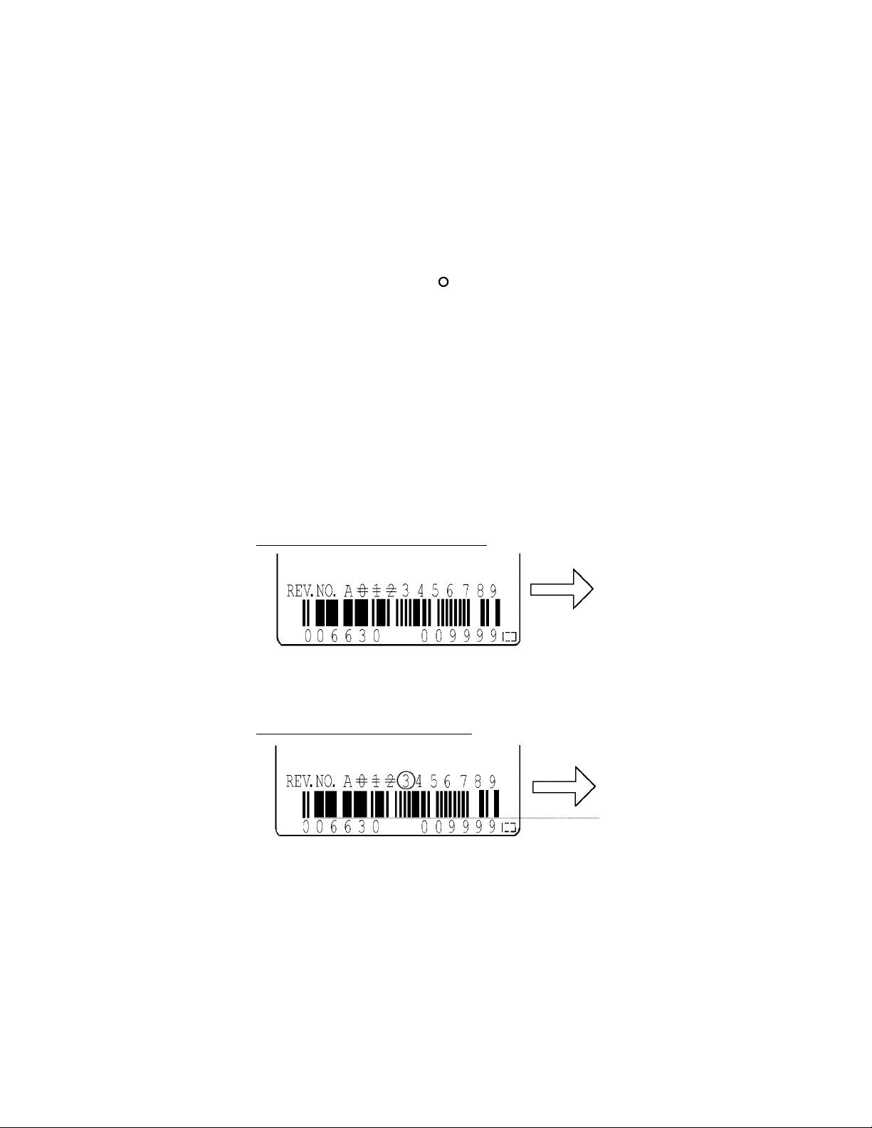
(1) Revision number marking at delivery
The machine revision number is indicated by crossing out up to the relevant number in the
relevant alphabetic character row using = marks (see Figure 1.2).
(2) Revision number change in the field
When a part is replaced in the field or other modifications are made, the machine revision
number may need to be changed. The level is indicated by crossing out the relevant number in
the relevant alphabetic character row using marks (see Figure 1.2).
(3) Firmware code and revision
First 2-digit indicates a firmware code and rest 2-digit indicates its revision.
Note:
For a change of revision number after delivery, Fujitsu issues a "Change Request/Notice"
and the disk drive revision number after the change. When a change is made at the user
site, the revision number level should be changed as described above.
Revision number mark when delivered
Revision number change in the field
Figure 1.2 Display of disk drive revision number
A2 Revision
A3 Revision
1 - 6 C141-F029-01EN
Page 20

1.1.5 Tools and test equipment
At the field maintenance level, only ordinary hand tools are required for troubleshooting and
repairing the disk drive. Special tools and test equipment is not required.
Factory level tools and test equipment are beyond the scope of this manual.
1.1.6 Self-diagnostics
The disk drive has the following self-diagnostics. These self-diagnostics allow normal basic
operation of an isolated disk drive can be checked.
• Initial self-diagnostics
• Offline self-diagnostics (EXECUTE DRIVE DIAGNOSTIC [DIAGNOSTIC] command)
1.1.7 Test
The disk drive test can be divided into the following three levels.
• Operating test (See Subsection 1.2.1 on Operating test.)
• Diagnostic test (See Subsection 1.2.2 on Diagnostic test.)
Figure 1.3 shows the relationship between the test level and troubleshooting.
Tables 1.1 and 1.2 show the check contents.
C141-F029-01EN 1 - 7
Page 21

Analyze the system
Test using voltage or
Diagnostic test with
Disk drive
Yes
Yes
Yes
YesNoNoNoNo
No
Yes
Yes
Check the host system
Continue with the
Operation test with the
Start
Disk drive failure
(Table 1.1)
host computer or test
equipment
Test acceptable?
operation
System normal?
replacement or repair
Disk drive normal?
the host computer or test
equipment
Test acceptable?
temperature stress
related failure
Test acceptable?
No failure
Figure 1.3 Test flowchart
1 - 8 C141-F029-01EN
analysis (Table 1.1)
Page 22

Table 1.1 Status register contents
Status bit Contents
BIT0 = 1 Shown in Table 1.2
BIT1, 2 Normal
BIT3 = 1
BIT4 = 1
BIT5 = 1
BIT6 = 0
BIT7 = 1
Error bit Method of disposition
BIT0, 4 (1) If an error occurs in a specific sector, treat that sector as a bad sector or replaced the
BIT1, 2 (1) Check the status of the host, cable and drive.
BIT6 Process the bad sector.
BIT7 (1) Check the status of the host, cable, power connector and drive.
(1) Check whether vibration is transmitted because of the way the disk drive is mounted.
(2) Check the power, cable, and connector.
(3) If it is concluded that the disk drive is the cause, replace the disk drive.
Table 1.2 Disposition for error register contents
sector.
(2) If errors occur frequently, check for problems with the power supply and the
mounting of the disk drive (disconnect the mainframe, power supply, and disk drive).
(3) If it is concluded that the disk drive is the cause, replace the disk drive.
(2) If it is concluded that the drive is the cause, replace the drive.
(2) If it is concluded that the drive is the cause, replace the drive.
1.2 Operation Confirmation
1.2.1 Operation test
When the host computer is processing data, the disk drive monitors disk drive operation errors
including data, command, and seek errors. The host is notified of the error that the disk drive
detected and the user is notified of its result.
The user may notice intermittent and indefinite failures such as overlong execution time,
abnormal noise, abnormal odor, or failures in particular processes.
The failure reported in the operation test will need further investigation. To ascertain the cause
of the disk drive failure reported, the disk drive can be replaced. Failures in the operation test
are often not caused by the host system. For example, not having enough power supply
reserve, a loose cable connection, no timing and mechanical reserves, or relationship with
other systems.
In normal operation, the disk drive itself or the host determines the processing (return or halt)
following the detected failure state.
C141-F029-01EN 1 - 9
Page 23

To troubleshoot the failure reported in the test at this level, accurately reproduce the condition
that caused the failure. Then, by replacing the disk drive, try to separate the fault from the
other sections of the disk drive host system.
1.2.2 Diagnostic test
The diagnostic test is used to separate a confirmed disk drive failure to a disk drive
subassembly or to check the disk drive performance. A test of this level usually includes a
specific disk drive function or concentrated execution of a group of functions. The test is
usually performed by a factory engineer and not where the failure was reported. The disk
drive is tested using another host computer or test equipment.
To troubleshoot the disk drive failure in the diagnostic test, the engineer will reproduce the
failure condition. The engineer then isolates the failure to a subassembly or part of the disk
drive.
The procedures used in a test of this level great depend on the test equipment used. It is
beyond the range of this manual.
1.3 Troubleshooting Procedure
1.3.1 Troubleshooting procedure
This section describes the troubleshooting procedures for a disk drive failure at field
maintenance level described in Subsection 1.1.3.
In this section, troubleshooting is made to isolate the reported failure to the disk drive or a host
system. Usually, troubleshooting is necessary only when a cause of failure is uncertain or
unknown. When a cause of failure is clear (for example, abnormal sound in the DE or burnt
parts on the PCA), a level of troubleshooting is low.
1.3.2 Troubleshooting disk drive replaced in field
It is recommended that the whole drive be replaced in maintenance of this level. If replacing
the drive corrects the fault, return the old drive to the factory for testing and repair. If the new
drive shows the same fault as the one that was removed, the failure is elsewhere in the system.
System level troubleshooting, shown in Table 1.3, is performed at the user site to isolate the
reported failure to the disk drive or system.
1 - 10 C141-F029-01EN
Page 24

Table 1.3 System level and field troubleshooting
Check to be made Recommended work
DC power cable Confirm that the power cable is properly connected at the disk drive and
power supply section.
DC power voltage
level
DC power ripple
noise
Interface cable
connection
Switch setting Confirm that the switch on the switch on the disk drive control PCA is set
System cable Confirm that all cable connections throughout the system correctly
System diagnostic
test
Intermittent or
indefinite error
Confirm that the DC power voltage is within ±5% (+5 VDC) or ±8% (+12
VDC) of the standard value.
When measured at pins 3 and 4 of the power supply connector, the +5 VDC
must be 4.75 to 5.25 VDC.
When measured at pins 1 and 2 of the disk drive power supply connector the
+12 VDC must be 11.04 to 12.96 VDC.
Check that the maximum ripple at +5 and +12 VDC power is less than
100 mV peak to peak and 200 mV peak to peak respectively.
Confirm that the AT interface cable is properly connected at the disk drive
and control unit.
for normal operation with the host computer. Refer to Section 3.4 in Product
Manual for switching setting.
connected.
To further isolate the failure, if it can be done, execute the system level
diagnostic routine described in the host computer manual.
Check the AC voltage level at the power supply section and recheck the DC
voltage level at the disk drive power supply connector.
If the AC voltage level is abnormal, or if there is a lot of electrical noise,
notify the user.
If the DC voltage level is unstable, replace the power supply section.
If possible, replace the disk drive. If the fault remains, the disk drive is not
the case. For suggestions to isolate the failure further, refer to the hardware
and software manuals provided with the system.
C141-F029-01EN 1 - 11
Page 25

1.3.3 Troubleshooting at factory
When the trouble is recovered by replacing the drive at field (Subsection 1.3.2), troubleshoot
the replaced drive to isolate the trouble to the subassembly parts.
To shorten the troubleshooting time and repairing time, gather the data, such as environmental
data and other information, from the user and then return the failed drive to the factory with
the media defect list to repair.
At the factory, user environment is made and a reappearance test is performed. To
reappearance a same trouble at user, the failed drive is connected to the host system. If no
trouble occurs by the normal test, the reappearance test is performed by adding the
voltage/temperature load using a disk drive tester or tools according to the user environment.
When a trouble reappeared, troubleshoot the cause of failure. Then, replace the failed unit or
parts.
As this level maintenance is made by a factory, this maintenance level is beyond the scope of
this manual.
The disk enclosure must never to opened in the field. Opening the
disk enclosure may cause irreparable damage.
1 - 12 C141-F029-01EN
Page 26

CHAPTER 2 REMOVAL AND REPLACEMENT
PROCEDURE
2.1 Spare Parts
2.2 Disk Drive Removal
This chapter explains the procedure for removing and replacing the disk drive. It is assumed that the
reader has a thorough knowledge of replacing the complete disk drive and replacing the powerinterface cable.
When carrying out these procedures, note the following items.
• The disk drive must have been removed from the host system.
• A power-interface cable to the disk drive must be disconnected.
• Mounting is done by reversing the steps for removal.
To carry out maintenance properly, observe the following:
• Place removed screws and other parts where they will not get lost or damaged.
• Keep a record of all maintenance work.
• Tighten screws securely but not excessively.
• Before touching the PCA, perform the human body grounding to discharge any static electricity
from your body. This ensures that the worker will not electrically damage the PCA.
2.1 Spare Parts
See Table 2.1 for the model and parts numbers to order the replacement disk drive.
C141-F029-01EN 2 - 1
Page 27

Table 2.1 Model and parts numbers
Model Part Number Formatted
MPC3032AT CA01675-B321 3243.66 MB
MPC3043AT CA01675-B331 4325.52 MB
MPC3064AT CA01675-B341 6488.29 MB
MPC3084AT CA01675-B561 8455.20 MB
MPC3096AT CA01675-B361 9747.58 MB
MPC3102AT CA01675-B661 10242.74 MB
2.2 Disk Drive Removal
The method and procedures to dismount the disk drive to check the jumper terminal, change
the jumper position, or replace the device differ depend on the system cabinet structure.
Therefore, for actual working procedures, the specific conditions necessary for each system
must be determined. The general removal procedures, with notes, is as follows.
a) Disconnect the power-interface cable.
b) Remove the screws that attach the drive and remove the drive from the system cabinet.
c) When storing or transporting the drive, pack it an antistatic bag.
Mounting Screw
capacity
No. 6-32UNC
Note:
To protect the device from damage and prevent the worker getting hurt, observe the parts
in Subsection 1.1.1 on Danger and Warnings.
1. Perform any removal after the system power is completely
disconnected. The cable must not be disconnected and the
screws that attach the drive must not be removed with the power
ON.
2. Do not move the drive until it comes to a complete stop (about
30 seconds after the power is turned OFF).
3. Perform the human body grounding to discharge any static
electricity from your body.
2 - 2 C141-F029-02EN
Page 28

This page is intentinally left blank.
Page 29

Comments concerning this manual can be directed to one of the following addresses:
FUJITSU LIMITED
Business Planning
Solid Square East Tower
580 Horikawa-cho,Saiwai-ku, Kawasaki,
210-0913, Japan
TEL: 81-44-540-4056
FAX: 81-44-540-4123
FUJITSU COMPUTER PRODUCTS OF AMERICA, INC.
2904 Orchard Parkway, San Jose,
California 95134-2009, U.S.A.
TEL: 1-408-432-6333
FAX: 1-408-432-3908
FUJITSU CANADA INC.
2800 Matheson Blvd. East, Mississauga, Toronto,
Ontario L4W 4X5, CANADA
TEL: 1-905-602-5454
FAX: 1-905-602-5457
FUJITSU EUROPE LIMITED
2, Longwalk Road, Stockley Park, Uxbridge,
Middlesex UB11 1AB, ENGLAND
TEL: 44-81-573-4444
FAX: 44-81-573-2643
FUJITSU DEUTSCHLAND GmbH
Frankfurter Ring 211, 80807 München, GERMANY
TEL: 49-89-323780
FAX: 49-89-32378100
FUJITSU NORDIC AB
Kung Hans Väg 12, S-192 68 Sollentura, SWEDEN
TEL: 46-8-626-6000
FAX: 46-8-626-6711
FUJITSU ICL ESPAÑA S.A.
Almagro 40, 28010 Madrid, SPAIN
TEL: 34-1-581-8100
FAX: 34-1-581-8125
FUJITSU AUSTRALIA LIMITED
2 Julius Avenue (Cnr Delhi Road) North Ryde N.S.W. 2113,
AUSTRALIA
TEL: 61-2-9776-4555
FAX: 61-2-9776-4556
FUJITSU HONG KONG LTD.
Room 2521, Sun Hung Kai Centre, 30 Harbour Road, HONG
HONG
TEL: 852-2827-5780
FAX: 852-2827-4724
FUJITSU KOREA LTD.
Coryo Finance Center Bldg, 23-6, YoulDo-Dong,
Young DungPo-Gu, Seoul, Republic of KOREA
TEL: 82-2-3787-6000
FAX: 82-2-3787-6070
FUJITSU COMPUTERS (SINGAPORE) PTE. LTD
20 Science Park Road #03-01,
TELETECH PARK SINGAPORE SCIENCE PARK II,
Singapore 117674
TEL: 65-777-6577
FAX: 65-771-5499
FUJITSU TAIWAN LTD.
8F, Hun Tai Center, 168-170, Tun Hwa North Road,
1st Sec., Taipei, TAIWAN
TEL: 886-2-545-7700
FAX: 886-2-717-4644
FUJITSU ITALIA S.p.A.
Via Nazario Sauro, 38 20099 Sesto S. Giovanni (MI), ITALY
TEL: 39-2-26294-1
FAX: 39-2-26294-201
FUJITSU FRANCE S.A.
I, Place des Etas-Unis, SILIC 310,
94588 Rungis Cedex, FRANCE
TEL: 33-1-41-80-38-80
FAX: 33-1-41-80-38-66
FUJITSU SYSTEMS BUSINESS (MALAYSIA) SDN. BHD.
Fujitsu Plaza, 1A, Jalan Tandang 204, P.O. Box 636 Pejabat Pos
Jalan Sultan
46770 Petaling Jaya, Selangor Darul Ehsan, Malaysia
TEL: 60-3-793-3888
FAX: 60-3-793-0888
FUJITSU SYSTEMS BUSINESS (THAILAND) LTD.
12th F1., Olympia Thai Tower, 444 Rachadapisek Road,
Samsennok, Huay Kwang, Bangkok 10320, Thailand
TEL: 66-2-512-6066
FAX: 66-2-512-6068
10
Page 30

Reader Comment Form
FUJITSU LIMITED
We would appreciate your comments and suggestions for improving this publication.
Publication No. Rev. Letter Title Current Date
How did you use this publication? Is the material presented effectively?
Learning
Reference
What is your overall rating of this publication? What is your occupation?
Very Good
Good
Your other comments may be entered here. Please be specific and give page,
paragraph and line number references where applicable.
Installing
Maintaining
Fair
Poor
Sales
Operating
Very Poor
Fully
covered
Well
Illustrated
Well
Organized
Clean
Thank you for your interest. Please send this sheet to one of the addresses in a left page.
Your Name & Return Address
Page 31

 Loading...