

Page 1

C141-E167-01EN
MAP3367, MAP3735, MAP3147 NP/NC SERIES
MAS3367, MAS3735 NP/NC SERIES
DISK DRIVES
SCSI LOGICAL INTERFACE SPECIFICATIONS
Page 2

FOR SAFE OPERATION
Handling of This Manual
This manual contains important information for using this product. Read thoroughly before using
the product. Use this product only after thoroughly reading and understanding especially the
section "Important Alert Items" in this manual. Keep this manual handy, and keep it carefully.
FUJITSU makes every effort to prevent users and bystanders from being injured or from suffering
damage to their property. Use the product according to this manual.
This product is designed and manufactured for use in standard applications such as office work,
personal devices and household appliances. This product is not intended for special uses (atomic
controls, aeronautic or space systems, mass transport controls, medical devices for life support, or
weapons firing controls) where particularly high reliability requirements exist, where the pertinent
levels of safety are not guaranteed, or where a failure or operational error could threaten a life or
cause a physical injury (hereafter referred to as "mission-critical" use). Customers considering the
use of these products for mission-critical applications must have safety-assurance measures in
place beforehand. Moreover, they are requested to consult our sales representative before
embarking on such specialized use
.
First Edition May 2002
T
his manual is for internal use only. Fujitsu takes no responsibility for any other use.
The contents of this manual may be revised without prior notice.
The contents of this manual shall not be disclosed in any way or reproduced in any media without
the express written permission of Fujitsu Limited.
All Rights Reserved, Copyright FUJITSU LIMITED 2002
C141-E167
Page 3

Revision History
(1/1)
Edition Date
01 May, 2002 — —
Revised section (*1)
(Added/Deleted/Altered)
Details
*1 Section(s) with asterisk (*) refer to the previous edition when those were deleted.
C141-E167
Page 4

This page is intentionally left blank.
Page 5

This manual explains concerning the MAS3367, MAS3735, MAP3367, MAP3735,
MAP3147 series 3.5 inch hard disk drives with internal SCSI controller.
The purpose of this manual is to provide specifications of each command and detailed
explanations of their functions for use of these magnetic disk drives incorporated into user
systems, and to present the information necessary for creating host system software. This
manual is written for users who have a basic kno wledge of hard disk drives and their use in
computer systems.
The composition of manuals related to these disk drives and the range of subjects covered
in this manual are shown in "Manual Organization," provided on a subsequent page.
Please use these other manuals along with this manual as necessary.
Remark:
Product development of MAK3728 described in this manual has been discontinued.
Overview of Manual
This manual consists of the following six chapters, glossary, abbreviation, and index:
Preface
Chapter 1 Command Processing
This chapter describes the basic logical specifications related to SCSI command processing
in the disk drives.
Chapter 2 Data Buffer Management
This chapter describes the data buffer configuration provided in the disk drives and
concerning data transfer processing functions and cache operation.
Chapter 3 Command Specifications
This chapter describes specifications of SCSI commands provided by the disk drives and
how to use them.
Chapter 4 Parameter Data Formats
This chapter describes the parameter data formats provided by the disk drives and how to
use them.
Chapter 5 Sense Data Error Recovery Methods
This chapter describes the configuration and contents of sense data which report to the host
system when an error occurs, etc., key information necessary for error recovery,
recommended procedures for error recovery to be executed through host system software
and retry processing executed internally in the disk drives for recovery
Chapter 6 Disk Media Management
C141-E167
This chapter describes the procedure for initializing the disk media, methods of treating
media defects and data recovery methods for the disk drives.
i
Page 6

Preface
Glossary
The glossary explains technical terms which are necessary to the reader's understanding
when reading this manual.
List of Abbreviations
This list shows the full spelling of abbreviations used in this manual.
The model name of disk drives covered by this manual differs in its ending suffix (Note 1)
depending on its device type (3 types), the electrical conditions of the SCSI interface used
to connect the disk drive to the host system and its capacity and data format at the time it
was shipped, but in this manual, except in cases where models need to be especially
distinguished, a representative model name (Note 2) is used. In addition, these disk drives
are called Intelligent Disk Drive (IDD), "drive" or "device" in this manu al.
Index
ii C141-E167
Page 7

CONVENTIONS USED INTHIS MANUAL
Note 1: Model Name
Preface
MAP3
Note 2: Typical model name
367 NC
Type model name Model name
MAS3367 MAS3367NP, MAS3367NC
MAS3735 MAS3735NP, MAS3735NC
MAP3367 MAP3367NP, MAP3367NC
MAP3735 MAP3735NP, MAP3735NC
MAP3147 MAP3147NP, MAP3147NC
Interface type NP: Low voltage differential 16-bit SCSI Ultra-320
NC: Low voltage differential 16-bit SCSI Ultra-320
SCA2 connector
Formatted capacity (1,000 MB units for MAP3147)
Formatted capacity (100 MB units for all the models except MAP3147)
Disk size
Type AS: 1-inch height (15,000 rpm)
AP: 1-inch height (10,025 rpm)
Warning Indications
The following warning indications are shown in this manual to prevent the user and other
nearby persons or property from being injured or damaged.
Note “Note” indicates the most effective method of use or information that is of value to
the user.
Requesting for User’s Comments
Please use the User’s Comment Form attached to the end of this manual to identify user
comments including error, inaccurate and misleading information of this manual. Contact
to your Fujitsu representative for additional comment forms if required.
C141-E167 iii
Page 8

Preface
Related Standards
Specifications and functions of products covered by this manual comply with the following
standards.
Standard (Text) No. Name Enacting Organization
ANSI X3. 131-1986 American National Standard for
ANSI X3. 131-1994 American National Standard for
X3T9.2/85-52 Rev 4.B COMMON COMMAND SET (CCS) of
X3T9.2 855D Rev 12 WORKING DRAFT Information
T10/1236-D Rev 19 Information technology SCSI Primary
T10 project 996D Rev 8C Information Technology --- SCSI-3 Block
X3T10/994D Rev 18 Information technology SCSI-3
T10/1302D Rev 14 Information technology SCSI Parallel
Information Systems --- Small Computer
System Interface (SCSI)
Information Systems --- Small Computer
System Interface-2 (SCSI-2)
the Small Computer System Interface
(SCSI)
Technology SCSI-3 Parallel Interface
Commands-2 (SPC-2)
Commands (S BC)
Architecture Model (SAM)
Interface-3 (SPI-3)
American National
Standards Institute
(ANSI)
American National
Standards Institute
(ANSI)
American National
Standards Institute
(ANSI)
American National
Standards Institute
(ANSI)
American National
Standards Institute
(ANSI)
American National
Standards Institute
(ANSI)
American National
Standards Institute
(ANSI)
American National
Standards Institute
(ANSI)
Attention
Please forward any comments you may have regarding this manual.
To make this manual easier for users to understand, opinions from readers are needed.
Please write your opinions or requests on the Comment at the back of this manual and
forward it to the address described in the sheet.
iv C141-E167
Page 9

MANUAL ORGANIZATION
Product/
Maintenance Manual
SCSI Physical
Interface Specifications
SCSI Logical Interface Specifications
(This Manual)
1. General Description
2. Specifications
3. Data Format
4. Installation Requirements
5. Installation
6. Diagnostics and Maintenance
7. Error Analysis
8. Principle of Operation
1. SCSI Bus
2. SCSI Messages
3. Error Recovery
1. Command Processing
2. Data Buffer Management
3. Command Specifications
4. Parameter Data Formats
5. Sense Data Error Recovery Methods
6. Disk Media Management
C141-E167 v
Page 10

This page is intentionally left blank.
Page 11

Contents
CHAPTER 1 Command Processing........................................................................................................1-1
1.1 Command Format..........................................................................................................................1-1
1.2 Status Byte.....................................................................................................................................1-6
1.3 Outline of Command Processing................................................................................................... 1-8
1.3.1 Single commands....................................................................................................................1-8
1.3.2 Command link ........................................................................................................................1-9
1.3.3 Disconnect/reconnect processing..........................................................................................1-11
1.3.4 Synchronous mode data transfer/wide mode data transfer...................................................1-15
1.4 Command Queuing Function .......................................................................................................1-16
1.4.1 Untagged queuing.................................................................................................................1-16
1.4.2 Tagged queuing....................................................................................................................1-18
1.5 UNIT ATTENTION Condition ...................................................................................................1-19
1.5.1 Generation of the UNIT ATTENTION condition ................................................................1-19
1.5.2 Response and release condition at UNIT ATTENTION condition hold
state.......................................................................................................................................1-20
1.5.3 UNIT ATTENTION condition multiple hold.......................................................................1-22
1.6 Sense Data Hold State..................................................................................................................1-22
1.6.1 Sense data hold condition.....................................................................................................1-22
1.6.2 Response and release conditions at sense data hold state.....................................................1-22
1.7 Command Processing Exceptions................................................................................................1-23
1.7.1 Overlapping commands........................................................................................................1-23
1.7.2 Illegal LUN specification......................................................................................................1-24
1.7.3 Reserved operation code.......................................................................................................1-24
1.7.4 Command processing in the not ready state .........................................................................1-24
1.7.5 Error recovery processing .....................................................................................................1-26
1.7.6 Reset processing ...................................................................................................................1-27
1.7.7 Fatal hardware errors............................................................................................................1-29
1.8 Data Block Addressing................................................................................................................1-29
1.8.1 Definition of data space........................................................................................................1-29
1.8.2 Logical block addressing......................................................................................................1-32
C141-E167 vii
Page 12

Contents
CHAPTER 2 Data Buffer Management................................................................................................ 2-1
2.1 Data Buffer.................................................................................................................................... 2-1
2.1.1 Data buffer configuration and basic operation....................................................................... 2-1
2.1.2 Operation mode setting.......................................................................................................... 2-5
2.2 Look-Ahead Cache Feature .......................................................................................................... 2-6
2.2.1 Caching operation.................................................................................................................. 2-6
2.2.2 Caching parameters................................................................................................................ 2-8
2.2.3 Look-Ahead operation, Look-Ahead volume........................................................................ 2-9
2.3 Write Cache ................................................................................................................................ 2-10
CHAPTER 3 Command Specifications.................................................................................................. 3-1
3.1 Control/Sense Commands............................................................................................................. 3-1
3.1.1 TEST UNIT READY (00)..................................................................................................... 3-1
3.1.2 INQUIRY (12)....................................................................................................................... 3-2
3.1.3 READ CAPACITY (25)...................................................................................................... 3-13
3.1.4 CHANGE DEFINITION (40).............................................................................................. 3-14
3.1.5 MODE SELECT (15) .......................................................................................................... 3-19
3.1.6 MODE SELECT EXTENDED (55) .................................................................................... 3-26
3.1.7 MODE SENSE (1A)............................................................................................................3-28
3.1.8 MODE SENSE EXTENDED (5A)...................................................................................... 3-34
3.1.9 REZERO UNIT (01)............................................................................................................ 3-35
3.1.10 START/STOP UNIT (1B)................................................................................................... 3-36
3.1.11 RESERVE (16).................................................................................................................... 3-37
3.1.12 RESERVE EXTENDED (56)............................................................................................. 3-40
3.1.13 RELEASE (17).................................................................................................................... 3-41
3.1.14 RELEASE EXTENDED (57)............................................................................................. 3-42
3.1.15 REQUEST SENSE (03)....................................................................................................... 3-42
3.1.16 LOG SELECT (4C)............................................................................................................. 3-44
3.1.17 LOG SENSE (4D) ............................................................................................................... 3-48
3.1.18 PERSISTENT RESERVE IN (5E)...................................................................................... 3-49
3.1.18.1 PERSISTENT RESERVE IN service actions............................................................... 3-50
3.1.18.1.1 READ KEYS...........................................................................................................3-50
3.1.18.1.2 READ RESERVATIONS ....................................................................................... 3-51
3.1.18.2 PERSISTENT RESERVE IN parameter data for READ KEYS.................................... 3-51
3.1.18.3 PERSISTENT RESERVE IN parameter data for READ RESERVATIONS................ 3-52
3.1.18.3.1 Persistent reservation scope..................................................................................... 3-53
3.1.18.3.2 Persistent reservations type ..................................................................................... 3-54
viii C141-E167
Page 13

Contents
3.1.19 PERSISTENT RESERVE OUT (5E)...................................................................................3-56
3.1.19.1 PERSISTENT RESERVE OUT service actions.............................................................3-57
3.1.19.2 PERSISTENT RESERVE OUT parameter list...............................................................3-58
3.1.20 REPORT LUNS (A0)...........................................................................................................3-60
3.1.21 REPORT DEVICE IDENTIFIER (A3)................................................................................3-62
3.1.22 SET DEVICE IDENTIFIER (A4)........................................................................................3-63
3.2 Data Access Commands ..............................................................................................................3-65
3.2.1 READ (08)............................................................................................................................3-65
3.2.2 READ EXTENDED (28)......................................................................................................3-66
3.2.3 WRITE (0A).........................................................................................................................3-67
3.2.4 WRITE EXTENDED (2A)...................................................................................................3-68
3.2.5 WRITE AND VERIFY (2E).................................................................................................3-69
3.2.6 VERIFY (2F)............................................................................................................... .........3-70
3.2.7 SEEK (0B)............................................................................................................................3-71
3.2.8 SEEK EXTENDED (2B)......................................................................................................3-71
3.2.9 SET LIMITS (33) (Not Supported)......................................................................................3-72
3.2.10 SYNCHRONIZE CACHE (35)............................................................................................3-74
3.3 Format Commands.......................................................................................................................3-75
3.3.1 FORMAT UNIT (04) ...........................................................................................................3-75
3.3.2 REASSIGN BLOCKS (07)...................................................................................................3-85
3.3.3 READ DEFECT DATA (37)................................................................................................3-88
3.4 Maintenance, Diagnostic Commands ..........................................................................................3-92
3.4.1 SEND DIAGNOSTIC (1D)..................................................................................................3-92
3.4.2 RECEIVE DIAGNOSTIC RESULTS (1C)..........................................................................3-98
3.4.3 WRITE BUFFER (3B) .......................................................................................................3-102
3.4.4 READ BUFFER (3C).........................................................................................................3-107
3.4.5 READ LONG (3E) .............................................................................................................3-111
3.4.6 WRITE LONG (3F)............................................................................................................3-112
3.4.7 WRITE SAME (41)............................................................................................................ 3-113
CHAPTER 4 Parameter Data Formats..................................................................................................4-1
4.1 Mode Parameters ...........................................................................................................................4-1
4.1.1 Read/Write error recovery parameters (page code = 1)..........................................................4-1
4.1.2 Disconnect/reconnect parameters (page code = 2) ...............................................................4-10
4.1.3 Format parameter (page code = 3)........................................................................................4-14
4.1.4 Drive parameter (page code = 4) ..........................................................................................4-17
4.1.5 Verify error recovery parameters (page code = 7)...............................................................4-19
C141-E167 ix
Page 14

Contents
4.1.6 Caching parameters (page code = 8).................................................................................... 4-21
4.1.7 Control mode parameters (page code = 0A)....................................................................... 4-27
4.1.8 Notch parameter (page code = 0C)...................................................................................... 4-31
4.1.9 Informational exceptions control page (page code = 1C).................................................... 4-33
4.1.10 Additional error recovery parameters (page code = 21)...................................................... 4-36
4.2 Log Parameters ........................................................................................................................... 4-37
4.2.1 Supprot log page (X'00')...................................................................................................... 4-38
4.2.2 Buffer overrun / underrun page (X'01') ............................................................................... 4-39
4.2.3 Write error count page (X'02').............................................................................................4-40
4.2.3.1 Write errors recovered without delays (Page 02, Code 0000) ...................................... 4-40
4.2.3.2 Write errors recovered with possible delays (Page 02, Code 0001) ............................. 4-41
4.2.3.3 Total posted write errors (Page 02, Code 0002)........................................................... 4-41
4.2.3.4 Total posted recoverable write errors (Page 02, Code 0003)........................................ 4-42
4.2.3.5 Total write bytes processed (Page 02, Code 0005)....................................................... 4-42
4.2.3.6 Total posted unrecoverable write errors (Page 02, Code 0006).................................... 4-43
4.2.4 Read error count page (X'03')..............................................................................................4-43
4.2.4.1 Read errors recovered without delays (Page 03, Code 0000)....................................... 4-44
4.2.4.2 Read errors recovered with possible delays (Page 03, Code 0001).............................. 4-44
4.2.4.3 Total posted read errors (Page 03, Code 0002) ............................................................ 4-45
4.2.4.4 Total posted recoverable read errors (Page 03, Code 0003)......................................... 4-45
4.2.4.5 Total read bytes processed (Page 03, Code 0005)........................................................ 4-46
4.2.4.6 Total posted unrecoverable read errors (Page 03, Code 0006)..................................... 4-46
4.2.5 Verify error count page (X'05')............................................................................................4-47
4.2.5.1 Verify errors recovered without delays (Page 05, Code 0000)..................................... 4-47
4.2.5.2 Vefiry errors recovered with possible delays (Page 05, Code 0001)............................ 4-48
4.2.5.3 Total posted verify errors (Page 05, Code 0002).......................................................... 4-48
4.2.5.4 Total posted recoverable verify errors (Page 05, Code 0003)...................................... 4-49
4.2.5.5 Total verify bytes processed (Page 05, Code 0005)..................................................... 4-49
4.2.5.6 Total posted unrecoverable verify errors (Page 05, Code 0006).................................. 4-50
4.2.6 Non-medium error count page (X'06')................................................................................. 4-50
4.2.7 Temperature page (X'0D').................................................................................................... 4-51
4.2.7.1 Temperature (Page 0D, Code 0000)............................................................................. 4-51
4.2.7.2 Reference temperature (Page 0D, Code 0001) ............................................................. 4-52
4.2.8 Start-stop cycle counter page (X'0E')................................................................................... 4-52
4.2.8.1 Date of manufacture (Page 0E, Code 0001)................................................................. 4-53
4.2.8.2 Accounting date (Page 0E, Code 0002)........................................................................ 4-53
4.2.8.3 Specified cycle count over device lifetime (Page 0E, Code 0003)............................... 4-54
x C141-E167
Page 15

Contents
4.2.8.4 Start-stop cycle counter (Page 0E, Code 0004).............................................................4-54
4.2.9 Application client page (X'0F')............................................................................................. 4-55
4.2.9.1 General usage application client parameter data (Page 0F, Code 0000-003F)..............4-55
4.2.10 Self-test result page (X'10')...................................................................................................4-56
4.2.10.1 Self-test result parameter data (Page 10, Code 0001-0014) ............................................4-56
4.2.11 SMART status page (X'2F')..................................................................................................4-57
4.2.12 SMART data page (X'38') ....................................................................................................4-57
CHAPTER 5 Sense Data Error Recovery Methods ..............................................................................5-1
5.1 Sense Data......................................................................................................................................5-1
5.1.1 Sense data format.................................................................................................................... 5-1
5.1.2 Sense data basic information ..................................................................................................5-2
5.1.3 Sense data additional information.........................................................................................5-11
5.2 INIT Error Recovery Methods (Recommended).........................................................................5-11
5.2.1 Termination status analysis and error recovery methods......................................................5-11
5.2.2 Sense data analysis and error recovery methods...................................................................5-14
5.2.3 Error logging ........................................................................................................................5-21
5.3 Disk Drive Error Recovery Processing........................................................................................5-22
5.3.1 Error states and retry processing procedures........................................................................5-22
5.3.2 Auto alternate block allocation processing...........................................................................5-23
5.3.3 Error recovery processing control ........................................................................................5-24
CHAPTER 6 Disk Media Management..................................................................................................6-1
6.1 Defect Management.......................................................................................................................6-1
6.2 Disk Media Initialization ...............................................................................................................6-3
6.2.1 Initialization during installation..............................................................................................6-3
6.2.2 Re-initialization ......................................................................................................................6-5
6.3 Data Block Verification Methods (Recommended).......................................................................6-6
6.4 Alternate Block Allocation Processing..........................................................................................6-7
Glossary .........................................................................................................................................GL-1
Abbreviations ......................................................................................................................................... AB-1
Index ..........................................................................................................................................IN-1
C141-E167 xi
Page 16

Contents
Illustrations
Figures
1.1 6-Byte CDB Basic Format..................................................................................................... ....... 1-1
1.2 10-Byte CDB Basic Format.......................................................................................................... 1-2
1.3 12-Byte CDB Basic Format.......................................................................................................... 1-2
1.4 Status Byte.................................................................................................................................... 1-6
1.5 Data space configuration............................................................................................................. 1-31
2.1 Data buffer configuration (in the case of 8 cache segments)........................................................ 2-2
2.2 Example of data buffer operation during read.............................................................................. 2-3
2.3 Example of data buffer operation during write............................................................................. 2-4
2.4 Parameters for controlling reconnection timing............................................................................ 2-5
2.5 Cache control parameters.............................................................................................................. 2-9
3.1 Standard INQUIRY data............................................................................................................... 3-4
3.2 Command support data................................................................................................................. 3-9
3.3 VPD information: VPD identifier list........................................................................................3-11
3.4 VPD information: device serial No............................................................................................ 3-11
3.5 VPD information: operation mode.............................................................................................3-12
3.6 READ CAPACITY data............................................................................................................. 3-14
3.7 MODE SELECT parameter structure ......................................................................................... 3-21
3.8 MODE SELECT command (Group 0) parameter configuration................................................ 3-23
3.9 MODE SELECT EXTENDED command (Group 2) parameter configuration.......................... 3-28
3.10 MODE SENSE command (Group 0) parameter configuration................................................... 3-31
3.11 MODE SENSE EXTENDED command (Group 2) parameter configuration............................. 3-35
3.12 SET LIMITS command: Specifying the range where access is permitted................................. 3-73
3.13 FORMAT UNIT command parameter list configuration............................................................ 3-78
3.14 Defect descriptor: Byte distance from index format.................................................................. 3-80
3.15 Defect descriptor: physical sector address format......................................................................3-81
3.16 REASSIGN BLOCK command: defect data list configuration................................................. 3-86
3.17 READ DEFECT DATA command: Defect data configuration................................................. 3-89
3.18 SEND DIAGNOSTIC command: parameter list configuration................................................. 3-95
3.19 SEND DIAGNOSTIC parameters: page code list ..................................................................... 3-96
3.20 SEND DIAGNOSTIC parameters: logical/physical address conversion................................... 3-96
3.21 RECEIVE DIAGNOSTIC RESULTS command: Response data configuration ....................... 3-99
3.22 RECEIVE DIAGNOSTIC RESULTS response data: page code list....................................... 3-100
3.23 RECEIVE DIAGNOSTIC RESULTS response data: logical/physical address conversion .... 3-101
3.24 WRITE BUFFER command: buffer data (Mode =000,001).................................................... 3-103
3.25 READ BUFFER command: buffer data (Mode =0000,0001)................................................. 3-108
3.26 READ BUFFER command: buffer descriptor......................................................................... 3-109
3.27 READ BUFFER command: Echo buffer descriptor................................................................ 3-110
xii C141-E167
Page 17

Contents
4.1 MODE SELECT parameters: read/write error recovery parameters............................................4-2
4.2 MODE SELECT parameters: disconnect/reconnect parameters.................................................4-10
4.3 MODE SELECT parameters: format parameters .......................................................................4-14
4.4 MODE SELECT parameters: drive parameters..........................................................................4-18
4.5 MODE SELECT parameters: verify error recovery parameters.................................................4-20
4.6 MODE SELECT parameters: caching parameters......................................................................4-22
4.7 MODE SELECT parameters: control mode parameters.............................................................4-28
4.8 MODE SELECT parameters: informal exception control page..................................................4-33
4.9 MODE SELECT parameters: additional error recovery parameters ..........................................4-36
5.1 Expanded sense data format ..........................................................................................................5-2
5.2 Sense key inherent information .....................................................................................................5-4
5.3 Analysis of the termination status................................................................................................5-12
Tables
1.1 Responses to Link Specification Commands...............................................................................1-10
1.2 Types of Command and Disconnect Processing..........................................................................1-12
1.3 Sense data in not ready state........................................................................................................1-25
1.4 Outline of SCSI Bus Error Recovery Processing.........................................................................1-26
1.5 Outline of disk drive error recovery processing ..........................................................................1-27
1.6 Reset processing during write......................................................................................................1-28
3.1 MODE SENSE Data Type Specifications ...................................................................................3-30
3.2 Persistent reservation type codes.................................................................................................3-55
3.3 PERSISTENT RESERVE OUT command service action codes.................................................3-58
3.4 PERSISTENT RESERVE OUT service actions and valid parameters........................................3-60
3.5 FORMAT UNIT command defect processing.............................................................................3-83
3.6 Error recovery control flags during the self-diagnosis test..........................................................3-96
4.1 Combinations of error recovery flags............................................................................................4-7
5.1 Sense key.......................................................................................................................................5-5
5.2 Sense and subsense codes ............................................................................................................. 5-6
5.3 Sense data error classification .....................................................................................................5-14
5.4 Error recovery processing procedures ........................................................................................5-17
5.5 Disk drive errors and number of retries.......................................................................................5-25
C141-E167 xiii
Page 18

This page is intentionally left blank.
Page 19
CHAPTER 1 Command Processing
1.1 Command Format
1.2 Status Byte
1.3 Outline of Command Processing
1.4 Command Queuing Function
1.5 UNIT ATTENTION Condition
1.6 Sense Data Hold State
1.7 Command Processing Exceptions
1.8 Data Block Addressing
This chapter describes the basic logical specifications of the IDD command processing functions.
Note: The IDD operates as the target (TARG) on the SCSI bus. In the explanations in this chapter, the
IDD is mentioned as “TARG”, except in cases where a particularly clear distinction is necessary.
1.1 Command Format
Input/output operation commands from INIT (initiator) to the IDD are accomplished by the CDB
(Command Descriptor Block). The CDB is information transferred from INIT to TARG in the
COMMAND phase. In a number of commands, the parameters which are necessary for command
execution in the DATA OUT phase may be specified in addition to the CDB specification. Details
concerning these are described in the specifications for each individual command in Chapter 3.
The CDB used by the IDD has 3 formats, these formats have length of 6, 10 and 12 bytes.
The basic format of each respective CDB is shown in Figures 1.1, 1.2 and 1.3.
Bit
Byte
0 Operation Code
1 LUN Logical Block Address (MSB)
2 Logical Block Address
3 Logical Block Address (LSB)
4 Transfer Data Length
5 Control Byte
76543210
Figure 1.1 6-Byte CDB Basic Format
C141-E167 1 - 1
Page 20

Command Processing
Bit
Byte
0 Operation Code
1 LUN 00000
2 Logical Block Address (MSB)
3 Logical Block Address
4 Logical Block Address
5 Logical Block Address (LSB)
600000000
7 Transfer Data Length (MSB)
8 Transfer Data Length (LSB)
9 Control Byte
Bit
Byte
76543210
Figure 1.2 10-Byte CDB Basic Format
76543210
0 Operation Code
1 LUN 00000
2 Logical Block Address (MSB)
3 Logical Block Address
4 Logical Block Address
5 Logical Block Address (LSB)
6 Transfer Data Length (MSB)
7 Transfer Data Length (LSB)
8 Transfer Data Length (MSB)
9 Transfer Data Length (LSB)
1000000000
11 Control Byte
Figure 1.3 12-Byte CDB Basic Format
The meanings of each of the fields in the CDB are explained below. Depending on the type of
command, the basic format of the CDB, the definitions of fields and their meanings may differ.
Details are described in the specifications for each individual command in Chapter 3.
1 - 2 C141-E167
Page 21

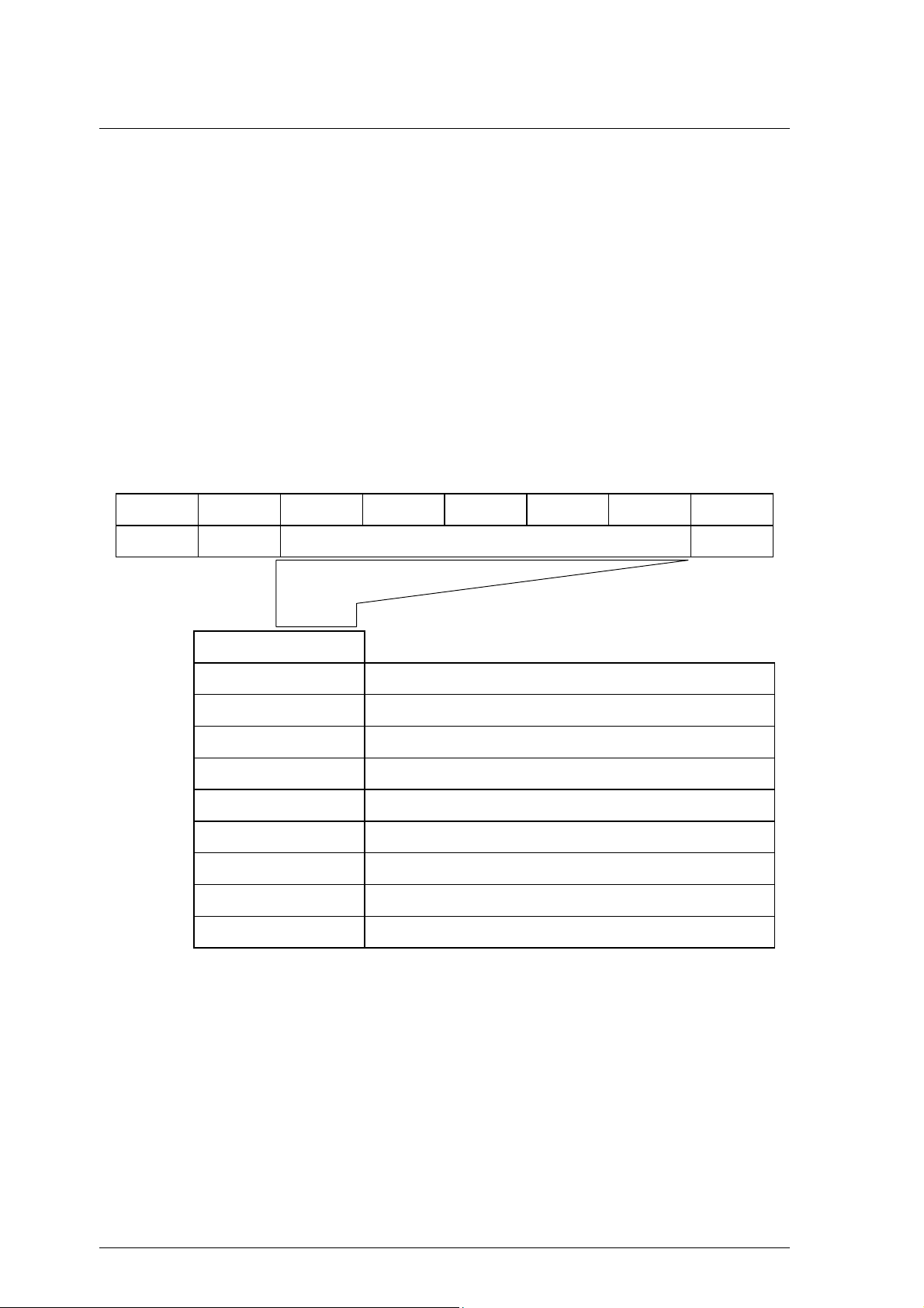
(1) Operation code
Bit 76543210
Group Code Command Code
The leading byte of all CDBs shows the format and type of command to be executed.
a. Group code
The group code specifies the number of bytes and format of the CDB. The groups of commands
shown below are used in the IDD.
• Group 0 (“000”):6-byte CDB (Shown in Figure 1.1)
• Group 1 (“001”):10-byte CDB (Shown in Figure 1.2)
• Group 2 (“010”):10-byte CDB (Shown in Figure 1.2)
• Group 3 ("011"):Reserved Operation Code (Shown in Section 1.7.3.)
• Group 4 ("100"):16-byte CDB
• Group 5 ("101"):12-byte CDB (Shown in Figure 1.3)
b. Command code
1.1 Command Format
Command code specifies the type of command in each group.
(2) LUN (Logical Unit Number)
This field specifies the address of the logical unit (device) connected under the TARG in cases where
the IDENTIFY message is not used. If the IDENTIFY message is used, the value of the CDB’s LUN
field is ignored when the LUN is specified.
Note:
It is possible that the definition of this field may be changed in future SCSI standards. It is
recommended that the LUN be specified using the IDENTIFY message, and that a zero be
specified in this CDB field.
(3) Logical block address
This field shows the leading logical data block address of the data block on the disk media to be
processed by the command. In the group 0 CDB, 21-bit block addressing is possible and in the group
1, group 2 and group 5 CDBs, 32-bit block addressing is possible. Specifications for logical data
block addressing in the IDD are described in Section 1.8.
(4) Transfer data length
In this field, the length of data to be transferred between INIT and TARG when the command is
executed is specified by the number of logical data blocks or the number of bytes. In subsequent
descriptions, the former is called the “transfer block count” and the latter is called the “transfer byte
length” or “parameter list length.”
C141-E167 1 - 3
Page 22

Command Processing
Furthermore, this field may be used with a different meaning, or it may not have any meaning at all,
depending on the type of command. There are also some commands which allocate 3 or more bytes
as the transfer data length field. Detailed specifications of these commands are described in the
individual command specifications in Chapter 3.
a. Transfer block count
When the “Transfer Data Length” is specified as the “Transfer Block Count,” this field specifies
the number of logical data blocks to be transferred between INIT and the IDD.
In commands where this field is 1 byte in length, if the field’s specified value is 0, it is regarded
as specifying 256 blocks, and it is possible to specify a block count ranging from 1 to 256 blocks.
On the other hand, in commands where this field is 2 bytes in length, if the field’s specified value
is 0, no data transfer is executed. It is possible to specify a block count ranging from 0 to 65,535
blocks.
b. Transfer byte length or parameter list length
When this field is specified as the “Transfer Byte Length” or “Parameter List Length,” that
command specifies data length to be transferred between the INIT and the IDD, expressed as the
number of bytes. When 0 is specified in this field, data transfer is not executed, except in cases
where it is expressly stated in the individual command specifications in Chapter 3.
In commands which send parameters necessary for executing a command from the INIT to the
IDD, this field is called the “Parameter List Length,” and it specifies the total number of types in
the parameter list which the INIT is sending.
On the other hand, in commands for receiving information from the IDD (REQUEST SENSE,
INQUIRY, etc.), this field is called the “Transfer Byte Length,” and specifies the maximum
number of bytes which the INIT can receive (the number of bytes of area secured within the
INIT for receiving information). The IDD transfers either the number of effective bytes of the
type of information specified in the command, or the value specified in the “Transfer Byte
Length” field, whichever is the smallest number of bytes, and only that number, to the INIT.
(5) Control byte
Bit 76543210
0000000Link
a. Link
Command link is specified by this bit is “1.” Details of the operation of the command link are
described in Section 1.3.2.
b. Bit 7, 6 (vendor unique)
Except in cases where it is expressly specified in the individual commands, specification of these
bits has no meaning, and the IDD disregards the specified values.
1 - 4 C141-E167
Page 23

Note:
It is possible that bits 7 and 6 of the control byte will be used in future product specifications
as an inherent control field. It is recommended that zeros be specified in this field.
(6) Handling an illegal CDB
If there is an error in the contents of a description (specification) in the CDB, or if there is an error in
the specifications in parameters transferred from the INIT by CDB specifying, that command ends
with a CHECK CONDITION status. In the case of a command to change the data on the disk media,
when there is an error in the CDB’s specifications, the disk media is not changed by that command.
But when there is an error in the parameters transferred in the DATA OUT phase, the contents of the
disk media in the range specified by the command may be changed. Also, even in cases where there
is an error in the CDB’s specifications in a command accompanying the DATA OUT phase, the
DATA OUT phase is executed after the COMMAND phase is terminated, but those data are not
used. For example, if there is an error in the CDB specification of a WRITE command, the IDD
executes the transfers several bytes of data (the data length to be transferred is not specified), but
those data are not written to the disk media. Details are described in the individual command
specifications in Chapter 3.
If there is an error in the CDB specification in a command which executes disconnect processing
(shown in Section 1.3.3), the disconnect processing may be executed after the COMMAND phase is
terminated. In this case, reconnect processing is executed afterward and the status (CHECK
CONDITION) is reported.
1.1 Command Format
Note:
If a CDB with an undefined group code (group 3, 4) is specified, the IDD requests transfer of 10
bytes in the COMMAND phase. After that has been received, the status (CHECK CONDITION)
is reported.
C141-E167 1 - 5
Page 24
Command Processing
1.2 Status Byte
Figure 1.4 shows status byte format and the type of status that the IDD supports.
The status byte is one byte of information sent from the TARG to the INIT in the STATUS phase
when one command is completed, and notifies the INIT of the results of the command’s execution.
The status byte is also sent even in cases when the TARG is in a state which it makes it impossible
for it to execute the command when it receives a request for an input/output operation. However, if
the command is cleared by switching to the BUS FREE phase forcibly through an ABORT TASK
SET message, an ABORT TASK message, a CLEAR TASK SET message, a TARGET RESET
message, a RESET condition or a SCSI bus error state, etc., the status byte for that command is not
reported.
After the TARG reports the status byte in the STATUS phase, it will always send a TASK
COMPLETE message or a LINKED TASK COMPLETE (WITH FLAG) message to notify the INIT
of the validity of the status byte.
Bit 76543210
0 0 Status Byte Code 0
Bit 5 4 3 2 1
(1) GOOD status
This status indicates that execution of the command ended normally.
0 0 0 0 0 GOOD Status
0 0 0 0 1 CHECK CONDITION Status
0 0 0 1 0 CONDITION MET Status
0 0 1 0 0 BUSY Status
0 1 0 0 0 INTERMEDIATE Status
0 1 0 1 0 INTERMEDIATE CONDITION MET Status
0 1 1 0 0 RESERVATION CONFLICT Status
1 0 0 0 1 COMMAND TERMINATED Status
1 0 1 0 0 QUEUE FULL Status
Figure 1.4 Status byte
1 - 6 C141-E167
Page 25

(2) CHECK CONDITION status
This status is reported in the following cases a) to c). The IDD generates sense data when it reports
this status and indicates the detailed cause. The INIT issues a REQUEST SENSE command when it
receives this status and should sample sense data.
a) If the sense key of the sense data indicates RECOVERED ERROR [=1], the last command,
which is the last command, indicates that it ended normally with the error recovery processing
executed by the IDD.
b) If the sense key of the sense data indicates UNIT ATTENTION [=6], it indicates that the IDD
was holding the UNIT ATTENTION condition. Details of the UNIT ATTENTION condition
are described in Section 1.5.
c) In cases other than the above, it indicates that command execution is impossible, or that
command execution was terminated abnormally.
(3) CONDITION MET Status
This status is reported when it is possible to secure the cache memory area necessary for reading all the
logical data blocks specified in the PRE-FETCH command (in the case of “Immed = 1”), or when reading
of all the specified logical data blocks is completed (in the case of “Immed = 0”).
1.2 Status Byte
The IDD does not support the PRE-FETCH command. Therefore, this status is not reported.
(4) BUSY status
This status indicates that the IDD is in the busy state and it cannot receive a new command.
Normally, an INIT that receives this status reissues the original command after waiting an appropriate
period of time.
The IDD reports the BUSY status in the following cases (the command stack function is explained in
Section 1.4).
a) If the IDD receives a new command while it is executing or is queuing command (except a
command without executing disconnect processing as shown in Section 1.3.3) but the INIT which
issued that command does not satisfy the disconnect enable conditions.
b) If the IDD receives a command without executing disconnect processing (as shown in Section
1.3.3) while it is executing or is queuing command.
c) If the DISCONNECT message for command queuing has been rejected by the INIT while the
IDD is executing or queuing command.
d) If a command with executing untagged disconnect processing is received while the command
queue is full.
(5) INTERMEDIATE status
This status indicates that a command which specifies a link (except the last command in a group of
linked commands with “1” as its Link bit) has been completed normally. If a command which
specifies a link is completed abnormally and the CHECK CONDITION status or RESERVATION
CONFLICT status is reported, the command link is broken an the subsequent linked commands are
not executed.
C141-E167 1 - 7
Page 26

Command Processing
(6) INTERMEDIATE CONDITION MET Status
This status is reported when it is possible to secure the cache memory area necessary to read all the
logical data blocks specified in a PRE-FETCH command which specifies a link (in the case of
“Immed = 1”), or when reading of all the specified logical data blocks is completed (in the case of
“Immed = 0”).
The IDD does not support the PRE-FETCH command. Therefore, this status is not reported.
(7) RESERVATION CONFLICT status
This status indicates that the IDD is reserved by another INIT, and that use is impossible until the
reserved status is canceled. Normally, an INIT which receives this status reissues the original
command after waiting an appropriate period of time.
(8) COMMAND TERMINATED status
This status is reported when the IDD has completed the executing input/output operation when it
received a TERMINATE I/O PROCESS message from the INIT.
(9) QUEUE FULL status
This status is reported if the IDD cannot register a received tagged command in the command queue
because there is no empty space in the command queue.
1.3 Outline of Command Processing
1.3.1 Single commands
Following shows single command processing examples which are the most basic operations on the
SCSI bus. Furthermore, if disconnect processing is permitted, it may be accompanied by
disconnect/reconnect processing during the command execution, depending on the type of command,
but this operation is omitted in the following explanation. The disconnect function is described in
Section 1.3.3.
1) The INIT sets the initial values for the command in the command pointer, data pointer and status
pointer.
2) The INIT selects the TARG in the SELECTION phase after obtaining the SCSI bus usage in the
ARBITRATION phase. After the SELECTION phase is ended, the SCSI bus control is entrusted
to the TARG.
3) If the ATTENTION condition exists when the TARG responds to the SELECTION phase, the
TARG executes the MESSAGE OUT phase. Normally, the INIT sends the IDENTIFY message
as the initial message and specifies the device (LUN) that is the object of the operation.
4) The TARG executes the COMMAND phase and receives the CDB from the INIT. The TARG
judges the length of the CDB by the group code in the first byte of the CDB and requests transfer
of the necessary number of bytes.
5) The TARG investigates the contents of the command and executes the requested operation. In
the case of commands for which data transfer on the SCSI bus is necessary, the DATA IN or the
DATA OUT phase is executed.
1 - 8 C141-E167
Page 27

6) When execution of the command is completed, the TARG reports the execution results by the
status byte in the STATUS phase to the INIT.
7) The TARG reports the TASK COMPLETE message to the INIT in the MESSAGE IN phase and
enters the BUS FREE phase.
1.3.2 Command link
The command link function is a function which causes the TARG to execute continuous processing
of multiple commands. Following shows examples of command link processing.
1) The INIT sets the initial values for the command in the command pointer, data pointer and status
pointer.
2) Obtaining the SCSI bus usage, selection of the TARG and specification of the LUN by the
IDENTIFY message are the same as in the case of single command.
3) The TARG receives commands from the INIT in the COMMAND phase, but “1” is specified in
the Link bit of the control byte of the CDB.
4) The TARG analyzes the command and executes the requested processing.
1.3 Outline of Command Processing
5) If processing of the command is completed normally, the TARG reports the INTERMEDIATE
status in the STATUS phase to the INIT. At this time, the command link function becomes
effective.
6) The TARG informs the INIT of the LINKED TASK COMPLETE or the LINKED TASK
COMPLETE WITH FLAG message, depending on the value of the Flag bit in the control byte of
the CDB. When the INIT has received the LINKED TASK COMPLETE (WITH FLAG)
message, the command, data and status pointers are updated to the initial values for the next
linked command.
7) The TARG enters the COMMAND phase immediately after the MESSAGE IN phase and
receives the command to be executed next. After that, it performs either single command (Link
bit = “0”) processing or command link (Link bit = “1”) processing.
The command link continues until a command with “0” specified in the Link bit of its CDB is issued
or until a command terminates abnormally.
The command link function is made effective only in the case that commands with link specifications
are completed normally. If a command with a link specification is completed in an error state or in
an exception state, the command link function is invalidated. Table 1.1 shows the response of the
IDD when commands with a Link specification are terminated.
C141-E167 1 - 9
Page 28

Command Processing
Flag End Status Status Message Link Function
Table 1.1 Responses to Link Specification Commands
0
1
×
0
1
×
×
×
×
Completed
Normally
Completed
Normally
Completed
Abnormally
Conditions Met INTERMEDIATE
Conditions Met INTERMEDIATE
Unable to Start
Receive
Reserved State RESERVATION
Forced
Termination
Queue Full State QUEUE FULL TASK COMPLETE Not Effective
INTERMEDIATE LINKED TASK COMPLETE Effective
INTERMEDIATE LINKED TASK COMPLETE WITH
FLAG
CHECK CONDITION TASK COMPLETE Not Effective
LINKED TASK COMPLETE Effective
CONDITION MET
LINKED TASK COMPLETE WITH
CONDITION MET
BUSY TASK COMPLETE Not Effective
CONFLICT
COMMAND
TERMINATED
FLAG
TASK COMPLETE Not Effective
TASK COMPLETE Not Effective
Effective
Effective
Only a single logical unit can operate a series of linked commands. When the IDD receives the first
command, the logical unit specified by the IDENTIFY message or the LUN field of the CDB
becomes the object of operation in a series of linked commands and the values specified in the LUN
field in the second and subsequent CDBs are disregarded.
Note:
An INIT which uses the command link function must make the ATN signal in the SELECTION
phase TRUE and notify the TARG that it is capable of receiving messages other than the
TASK
COMPLETE message. If “1” has been specified in the Link bit of the CDB without the ATN
being made TRUE by the INIT in the SELECTION phase, the IDD terminates that command
abnormally by sending a CHECK CONDITION status (ILLEGAL REQUEST [=5] / Invalid field
in CDB [=24-00]).
1 - 10 C141-E167
Page 29

1.3 Outline of Command Processing
1.3.3 Disconnect/reconnect processing
When processing is performed by the TARG during the command execution process which does not
require operation on the SCSI bus, the TARG can return the SCSI bus to the BUS FREE phase
temporarily by disconnect processing and execute command internally. Through this function, the
INIT is enabled to process multiple commands on the SCSI bus.
(1) Disconnect permission conditions and commands with executing disconnect process
If all of the conditions shown below for permitting a disconnect are satisfied, the IDD executes
disconnect processing. However, As shown in Table 1.2, disconnect processing may be valid or
invalid, and the disconnect processing execution timing may differ, depending on the type of
command.
Conditions for Permitting a Disconnect
1) The SCSI ID of the INIT is notified in the SELECTION phase.
2) The INIT generates the ATTENTION condition in the SELECTION phase.
3) The INIT notifies the TARG that disconnect processing is permitted by an IDENTIFY message.
C141-E167 1 - 11
Page 30

Command Processing
Table 1.2 Types of Command and Disconnect Processing
Commands with executing disconnect processing. (Note 2)
Commands without executing disconnect processing. (Note 1)
C CHANGE DEFINITION (40) O
F FORMAT UNIT (04) O
I INQUIRY (12) O
L LOG SELECT (4C) O
LOG SENSE (4D) O
M MODE SELECT (15) O
MODE SELECT EXTENDED (55) O
MODE SENSE (1A) O
MODE SENSE EXTENDED (5A) O
N
P PERSISTENT RESERVE IN (5E) O
PERSISTENT RESERVE OUT (5F) O
R READ (08) O
READ BUFFER (3C) O
READ CAPACITY (25) O
READ DEFECT DATA (37) O
READ EXTENDED (28) O
READ LONG (3E) O
REASSIGN BLOCKS (07) O
RECEIVE DIAGNOSTIC RESULTS (1C) O
RELEASE (17) O
REPORT DEVICE IDENTIFIER (A3) O
REPORT LUN (A0) O
REQUEST SENSE (03) O
RESERVE (16)
REZERO UNIT (01) O
S SEEK (0B) O
SEEK EXTENDED (2B) O
SEND DIAGNOSTIC (1D) O
SET DEVICE IDENTIFIER (A4) O
START/STOP UNIT (1B) O
SYNCHRONIZE CACHE (35) O
T TEST UNIT READY (00) O
VVERIFY (2F) O
WWRITE (0A) O
WRITE AND VERIFY (2E) O
WRITE BUFFER (3B) O
WRITE EXTENDED (2A) O
WRITE LONG (3F) O
WRITE SAME (41) O
(Note 1) Commands without executing disconnect processing: In cases only where commands are issued
without a tag, queuing processing (see Section 1.4) and disconnect processing cannot be
performed in the execution sequence.
(Note 2) Commands with executing disconnect processing: Regardless of command queuing, in a command’s
execution process (after the COMMAND phase is completed, or during or after the completion of data
transfer), disconnect processing is performed. However, in the case of commands with a data state (in
cases where it is hit in the cache, etc.), or with a number of processing modes, other than cases where
the command is in a queue, disconnect processing may not be executed depending on the processing
content specification of the command.
1 - 12 C141-E167
Page 31

(2) Basic disconnect processing procedure
Disconnect processing is executed basically by the following processing procedure.
1) If the IDD judges that it is possible for it to disconnect from the SCSI bus during execution of a
command, it sends a DISCONNECT message to the INIT and enters the BUS FREE phase. At
this time, if necessary, the IDD sends a message to activate a pointer in the INIT which precedes
sending of the DISCONNECT message. Furthermore, for details concerning pointers, refer to
the SCSI pointer description in “SCSI Physical Interface Specifications” and “Chapter 2 SCSI
Messages.”
2) After the IDD enters the BUS FREE phase, it is possible for the INIT to issue other commands.
Also, it is possible for an IDD which has performed disconnect processing to receive input/output
operation requests from each INIT (this is explained in the description of the command queuing
function in Section 1.4).
3) The IDD executes the command which performs disconnect processing internally.
4) After that, the IDD executes reconnection processing at the point, when it is necessary for
operation on the SCSI bus, to reconnect with the INIT (See item (6) concerning reconnection
processing).
1.3 Outline of Command Processing
(3) Disconnect processing procedure after COMMAND phase execution
If commands are queued (see Section 1.4), disconnect processing is performed immediately after the
COMMAND phase execution is completed. In this case, the IDD switches from the COMMAND phase to
the MESSAGE IN phase and sends the DISCONNECT message to the INIT.
(4) Disconnect processing procedure after data transfer execution
For commands which accompany a data transfer, disconnect processing may be performed during
DATA IN or DATA OUT phase execution or after transfer of the last data is completed. In this case,
caution is necessary when executing the following types of pointer controls.
a. If disconnecting during a data transfer
In cases where data transfer has begun (in DATA IN or DATA OUT phase) and it will take time
until transfer of subsequent data can be transferred (example: When the data buffer has been
emptied by a READ command, or the data buffer has ceased to be empty due to a WRITE
command), disconnect processing is performed during data transfer. In this case, the IDD sends the
SAVE DATA POINTER message before sending the DISCONNECT message. When the INIT
receives the SAVE DATA POINTER message, it must save the current value of the current data
pointer and make it possible to transfer data from the subsequent data at reconnection time.
b. If disconnecting after the final data transfer is completed
In the case of a disconnect after transfer of all the data necessary for execution of a command has
been completed normally, (example: a WRITE command), the IDD sends a DISCONNECT
message after sending the SAVE DATA POINTER message.
After that, the IDD executes reconnection processing and enters the STATUS phase immediately
and reports the status byte without requesting a data transfer.
C141-E167 1 - 13
Page 32

Command Processing
Note:
In disconnect processing in this case, transfer of all the data accompanying execution of the
command is complete and there is actually no necessity for the SAVE DATA POINTER
message.
However, by issuing the SAVE DATA POINTER message, processing time increases due to
the message transfer, but as a result of the pointer restore operation that is executed
internally by the INIT during reconnection processing for the status report, the current data
pointer can reflect the final results of the data transfer.
(5) Disconnect processing exceptions
When the previously mentioned disconnect processing is executed, if the ATTENTION condition is
generated for the DISCONNECT message sent by the IDD and the INIT returns the MESSAGE REJECT
message, the IDD executes the command with the connections to the SCSI bus remaining as is, without
executing disconnect processing. Cases of disconnect processing in which a pointer operation is necessary
and the SAVE DATA POINTER message is rejected are the same.
(6) Reconnection processing procedure
The reconnection processing procedure is as shown below.
1) The IDD executes the ARBITRATION phase at the point when processing on the SCSI bus is
necessary and gets the SCSI bus control right, then reconnects with the INIT in the
RESELECTION phase.
2) After that, the IDD sends the IDENTIFY message to the INIT and notifies it of the logical unit
number (LUN) necessary for reconnection processing. If a tagged queuing command is executed,
the IDD sends the SIMPLE message to inform the INIT of the tag ID. The INIT reads the Saved
pointer (command, data and status) corresponding to the LUN specified at this time and restores
it to the current pointer.
Note:
1) If there is no response from the INIT within the specified time (default: 250 ms) in the
RESELECTION phase, the IDD performs timeout processing, then enters the BUS
FREE phase. In this case, after waiting 200 ms or longer, the IDD executes the
predetermined number of retries (re-executing the RESELECTION phase). However,
if it still cannot reconnect with the INIT after that, the IDD clears the command
necessary for reconnection processing and generates sense data indicating ABORTED
COMMAND[=B]/Select /Reselect failure[=45-00].
2) If the INIT rejects the IDENTIFY message, or if it rejects the SIMPLE message when
executing a tagged queuing command, the IDD clears the command that was being
executed during reconnection processing and enters the BUS FREE phase. In this case,
the IDD generates sense data indicating ABORTED COMMAND[=B]/Message
error[=43-00].
1 - 14 C141-E167
Page 33

3) After the INIT that accepts the IDENTIFY message normally completes the pointer
restore operation, it should make the ACK signal for the IDENTIFY message FALSE.
If the ATTENTION condition does not exist when the ACK signal becomes FALSE
during sending of the IDENTIFY message, the IDD regards the reconnection
processing as having been normally completed and begins subsequent processing.
For further details, refer to CHANGE DEFINITION parameter list (Reselection Retry,
Reselection Time-out Delay) in Section 3.1.4 and SCSI Bus (RESELECTION phase)
in Chapter 1 of “SCSI Physical Interface Specifications” and SCSI Bus Error Recovery
Processing in Chapter 3.
1.3.4 Synchronous mode data transfer/wide mode data transfer
The IDD equips a synchronous mode data transfer function and wide mode data transfer function for
processing high speed data transfers (DATA IN and DATA OUT phases) on the SCSI bus. Data
transfers on the SCSI bus can be executed in any desired combination of the asynchronous mode or
synchronous mode and in 8 bit widths or 16 bit widths (wide mode), but by using synchronous mode
data transfer or wide mode data transfer, command processing time is shortened and throughput for
input/output processing by multiple command processing using idle time on the SCSI bus can be
improved.
After IDD power on, after generating a RESET condition on the SCSI bus or after one of the INITs
issues a TARGET RESET message, the data transfer mode (default mode) of the IDD is the
asynchronous mode. To use wide mode data transfer, the INIT must exchange a WIDE DATA
TRANSFER REQUEST message or PARALLEL PROTOCOL REQUEST message with the IDD,
and determine the SCSI bus width. To use the synchronous mode data transfer, the INIT must
exchange the SYNCHRONOUS DATA TRANSFER REQUEST message or PARALLEL
PROTOCOL REQUEST message and determine parameters necessary for executing the synchronous
mode transfer. When exchange of the WIDE DATA TRANSFER REQUEST message or
PARALLEL PROTOCOL REQUEST message is completed, if the synchronous mode has been
established between the INIT and IDD previously, note that the asynchronous mode is set.
1.3 Outline of Command Processing
The INIT which uses wide mode data transfer normally sends the WIDE DATA TRANSFER
REQUEST or PARALLEL PROTOCOL REQUEST message to the IDD following the IDENTIFY
message after the initial SELECTION phase, and requests the TARG (IDD) to set the SCSI bus width
in the wide mode. Also, if synchronous mode data transfer is used, after establishing the SCSI bus
width, the INIT exchanges the SYNCHRONOUS DATA TRANSFER REQUEST message or
PARALLEL PROTOCOL REQUEST message and requests the TARG (IDD) to set the synchronous
data transfer mode.
The data transfer mode set with the INIT once is effective until a RESET condition occurs or until a
TARGET RESET message is issued by any INITs. Therefore, in order for the INIT to avoid
overhead time for message exchange, the INIT should not send the WIDE DATA TRANSFER
REQUEST message and the SYNCHRONOUS DATA TRANSFER REQUEST message or
PARALLEL PROTOCOL REQUEST message to the TARG each time the SELECTION phase is
executed.
When the requesting synchronous mode transfer/wide mode data transfer by specifying of the
CHANGE DEFINITION command (synchronous mode transfer/wide mode data transfer request) is
permitted, and the IDD is maintaining the default transfer mode (asynchronous, 8-bit width), if a
WIDE DATA TRANSFER REQUEST message is not sent from the INIT, the IDD enters the
MESSAGE IN phase immediately after the COMMAND phase and sends the WIDE DATA
TRANSFER REQUEST message to the INIT for attempting to set the 16-bit width mode. After
establishing the bus width, the IDD sends the SYNCHRONOUS DATA TRANSFER REQUEST
message to the INIT and attempts the synchronous mode transfer parameters (REQ/ACK offset =
127, Transfer period = 25 ns).
C141-E167 1 - 15
Page 34

Command Processing
The IDD maintains data transfer mode settings between itself and each INIT individually. Therefore,
an INIT which uses asynchronous mode transfer and an INIT which uses synchronous mode transfer
can both coexist on the same SCSI bus. Also, the parameters for synchronous mode transfers decided
by the SYNCHRONOUS DATA TRANSFER REQUEST message can differ for each INIT and an
INIT which uses the 8-bit width transfer mode can coexist with an INIT which uses the 16-bit width
transfer mode.
Note:
When the INIT issues the first command after the TARG’s power is switched on, or after a
RESET condition occurs, it can send the WIDE DATA TRANSFER REQUEST message and the
SYNCHRONOUS DATA TRANSFER REQUEST message. However, when the TARG is set
internally on a data transfer mode established previously by a TARGET RESET message issued
by another INIT, generally, the INIT is not aware of it. In such case, when requesting
synchronous mode/wide mode transfer is permitted by the specification of the CHANGE
DEFINITION command (synchronous mode/wide mode transfer request), the TARG (IDD)
sends the WIDE DATA TRANSFER REQUEST and SYNCHRONOUS DATA TRANSFER
messages to establish the synchronous mode/wide mode transfer again. Thus, the INIT shall
respond to these messages for setting necessary parameters again.
See “CHANGE DEFINITION” in Section 3.1.4, SCSI Bus (INFORMATION TRANSFER Phase) in
Chapter 1 and SCSI Messages (SYNCHRONOUS DATA TRANSFER REQUEST, WIDE DATA
TRANSFER REQUEST, PARALLEL PROTOCOL REQUEST) in Chapter 2 of “SCSI Physical
Interface Specifications” for further details.
1.4 Command Queuing Function
The IDD equips a command queuing function. Through queuing of commands, the IDD can receive
multiple commands in advance and execute them.
There are two methods used in the queuing function, tagged and untagged. In tagged queuing, the
IDD can receive multiple commands from each INIT. In untagged queuing, the IDD can receive a
single command from each INIT.
Both queuing methods are possible for the IDD, but an INIT can use only one queuing method at a
time. However, if another INIT selects a different method, the IDD controls both methods of
command queuing.
1.4.1 Untagged queuing
Using untagged queuing, the IDD can receive a command from an INIT while it is executing
processing of a command from another INIT. The IDD can receive one command at a time from
each INIT. It is the role of the INIT to confirm that only one command is issued every time.
When the IDD receives a new command from an INIT, if it is processing another command from a
different INIT, or if it is currently executing its initial self-diagnosis, that command is queued in the
command queue. In this case, the IDD executes disconnect processing after command queuing
processing is completed.
After the IDD finishes executing the current processing command, if there is a command in the
queue, it fetches that command and executes it. If there are multiple commands in the queue, they are
fetched and executed in the order in which they were received.
1 - 16 C141-E167
Page 35

1.4 Command Queuing Function
When a command is in the queued state, if a RESET condition occurs, or if the IDD receives a
TARGET RESET message from any INIT, it clears all the commands in the queue. At this time, the
IDD generates on UNIT ATTENTION condition for all the INITs.
When an ABORT message is sent from an INIT that has issued a command which is in the queue, if
the correct LUN (0) is specified, only the command issued by that INIT is cleared and the other
commands in the queue are not effected. If the LUN is not identified, an ABORT message which
specifies an illegal LUN (1 to 7) does not effect the commands in the queue.
Untagged queuing exception processing (events and operations executed by the IDD) is shown
below.
• If the TEST UNIT READY, REQUEST SENSE or INQUIRY command is received.
When one of these commands is received, if there is no link instruction in that command, the IDD
executes that command immediately without queuing the command or executing disconnect
processing. At this time, there is no effect on the commands from other INITs which are currently
being executed, or on the commands in the queue.
If these commands contain link instructions, they are queued.
• If disconnect processing is impossible.
If disconnect processing is impossible because the INIT which issued the command does not meet the
conditions for permitting a disconnect (see Section 1.3.3), or if the DISCONNECT message is
rejected by the INIT even though it meets the conditions for permitting a disconnect, the IDD
responds with a BUSY status without queuing the received command except the case described in
item 1) in following Note during executing or queuing command already. If this is not the case, the
received command is executed immediately.
• If the IDD is reserved
If the IDD has been reserved by an INIT using the RESERVE command and receives a TEST UNIT
READY command after that, when that command conflicts with the reserved state, it responds with a
RESERVATION CONFLICT status. Commands after that are queued, and the reserved state is
checked when a command is fetched from the queue. Conflicts with the reserved state are explained
in the description of the RESERVE command (Section 3.1.11).
Note:
Through the operation of the command queuing function, except for exceptions described on this
page, the IDD does not respond to commands issued by the INIT with a BUSY status. This
function is applied under the multi-initiator environment, and overhead for re-issuing commands
caused by the BUSY status is unnecessary. Normally, the INIT does not have to be aware of the
existence of a queuing function, but it is necessary to exercise caution in the following items
when controlling input/output processing.
1) When a command is queued, the time from the queuing of the command to its actual
execution will vary depending on the commands already in the queue, or on the content of
the processing currently being executed. Particularly in cases where the FORMAT UNIT
command and START/STOP UNIT command (Immed = 0), and data access commands
which specify large processing block counts, are already queued or being executed, the
newly queued command will be forced to wait a long time until it is executed.
2) In the following cases, a command may not be executed even after it has been queued.
C141-E167 1 - 17
Page 36

Command Processing
a) When there is an error in the CDB, the IDD responds with a CHECK CONDITION
status at the point when that command is fetched from the queue.
b) If the IDD is in the not ready state at the point when the queued command is fetched, it
responds with a CHECK CONDITION status.
c) If a UNIT ATTENTION condition is generated before the queued command is fetched,
a CHECK CONDITION status may be replied.
1.4.2 Tagged queuing
Through the tagged queuing function, the IDD can receive multiple commands from the same INIT
or from different INITs until the command queue is full. The number of commands that it is possible
to receive by the IDD is 128 maximum, without relation to the INIT. When the IDD receives a new
command, if the command queue is full, it responds to the new command with the QUEUE FULL
status.
The IDD manages the command queue, but it is possible for the INIT to add or clear commands from
the queue. When adding a command to the queue, it is possible for the INIT to specify the order in
which commands should be executed or the command that should be executed next to the IDD.
If the disconnect right is not recognized in the IDENTIFY message of a tagged command, the IDD
responds with a BUSY status.
Through the QUEUE TAG message, the INIT can attach a unique tag (ID) to each command. The
INIT can set that command’s pointer correctly by the tag sent when the IDD reconnects. One INIT
can issue multiple commands to the IDD only when the respective commands have unique tags.
If an ORDERED message is used, the IDD executes the other commands not included in the
ORDERED message in the order in which they are received. All commands received with a SIMPLE
message before commands are received with an ORDERED message are executed before those
commands received with the ORDERED message. All commands with SIMPLE messages received
after commands received with the ORDERED message are executed after the commands received
with the ORDERED message.
Commands received with a HEAD OF QUEUE message are registered at the top of the queue for
waiting execution. The IDD does not interrupt the current command execution and executes them
after completion of current command execution. When commands with the HEAD OF QUEUE
message are received continuously, the IDD first executes the command which was received last.
During the IDD executes or queues a tagged command, the same INIT must issue untagged
commands except when the IDD is in the sense hold state.
The IDD handles a series of linked commands as if it were processing a single command and
processes the series of commands by the tag received with the first command. A command with a
HEAD OF QUEUE received before processing of a series of linked commands is completed is
executed by the IDD after all the linked commands in the series have been executed.
The RESERVE, RELEASE and RESERVE EXTENDED commands should be issued together with
an ORDERED message. If the HEAD OF QUEUE message is used with these commands,
previously issued commands and reserved states may become redundant.
The TEST UNIT READY and INQUIRY commands do not influence the state of the IDD, so they
can be issued together with a HEAD OF QUEUE message.
1 - 18 C141-E167
Page 37

1.5 UNIT ATTENTION Condition
The INIT can specify 2 error recovery options by the QErr bit of the control mode parameter (Page
A) of the mode select parameters.
When “0” is specified in the QErr bit, the IDD enters any one of a number of sense hold states, and
when this state is released, it continues to execute the commands in the queue. The IDD queues any
commands received from other INITs while it is in the sense hold state, but during this period,
execution of all the commands in the queue is interrupted.
If “1” is specified in the QErr bit, if the IDD enters any one of a number of sense hold states, the
queue is cleared after the sense hold state is released. When the queue is cleared through this
recovery option, the UNIT ATTENTION condition is generated for all the INITs which had their
commands cleared (excluding the INIT that set the sense hold state). The sense code Commands
cleared by another INIT [=2F-00] is set.
Deferred errors are reported for all commands that have already been completed. Therefore, the
queue tag values attached to those commands are not reported.
If a QUEUE TAG message is received by the IDD when tagged commands are prohibited by the
DQue bit of the control mode page, the IDD rejects the message with the MESSAGE REJECT
message processes the accompanying command as an untagged command.
The ABORT TASK SET, ABORT TASK, TARGET RESET or CLEAR TASK SET message is
used to clear some or all of the commands in the queue. See “SCSI Physical Interface
Specifications” for details.
If ‘0001’ is specified in the Queue algorithm modifier of the control mode page, the IDD performs
command reordering processing of commands issued with a SIMPLE message. Reordering
processing is performed with the objective of reducing total processing time for command
processing.
• Conditions for Reordering:
If a command which is the object of reordering is issued by an INIT that permits reordering with
an accompanying SIMPLE message.
• Commands which are Objects of Reordering:
READ, READ EXTENDED, WRITE, WRITE EXTENDED
If an INIT permits command reordering processing, the IDD changes the processing order of the
commands. It is necessary for the INIT to manage concerning the legality of the data, etc.
Section 4.1.7, “Control mode parameters (page code = 0A)” for details of the control mode page.
1.5 UNIT ATTENTION Condition
The UNIT ATTENTION condition is a function used to notify the INIT asynchronously of an event
(status change) that has occurred in the TARG or logical unit.
1.5.1 Generation of the UNIT ATTENTION condition
Events which cause a UNIT ATTENTION condition to be generated are one of the following.
C141-E167 1 - 19
Page 38

Command Processing
(1) When power on, RESET or TARGET RESET occurs
If the IDD’s power is switched on, the IDD enters the RESET condition or is reset by a TARGET
RESET message, this UNIT ATTENTION condition is generated for all the INITs, regardless of
whether the disk drive is in the ready state or not.
(2) Mode parameters changed (changed by another INIT)
If the parameters specified in the MODE SELECT or MODE SELECT EXTENDED command are
changed by any INIT, a UNIT ATTENTION condition is generated for all the INITs other than the
INIT which changed the parameters.
(3) Commands cleared by another INIT
Commands which are being executed or which are queued are cleared if one of the following events
occurs, and this UNIT ATTENTION condition is generated.
• The CLEAR TASK SET message is issued by any INIT.
• Tagged queuing is prohibited by a MODE SELECT or MODE SELECT EXTENDED command
(Page A send) from any INIT. (DQue = “1”)
• The sense hold state of an INIT is released when “1” is specified in the QErr bit of MODE
SELECT parameter page A.
However, the IDD does not enter the UNIT ATTENTION condition hold state for an INIT that
issues a CLEAR TASK SET message, an INIT that issues a MODE SELECT or MODE SELECT
EXTENDED command, or an INIT that releases the sense hold state.
(4) Changed operating definition
When the operation mode is changed by the CHANGE DEFINITION command, the UNIT
ATTENTION condition is generated for all INITs.
1.5.2 Response and release condition at UNIT ATTENTION condition hold state
A UNIT ATTENTION condition generated by the IDD by the occurrence of the previously
mentioned events is held individually for each INIT and it is held until it is released by the INIT it is
held for issuing the commands specified below.
When the IDD is holding a UNIT ATTENTION condition, if the IDD receives a command from the
INIT that the UNIT ATTENTION condition is held for, it performs one of the following operations
depending on the type of command issued.
(1) Commands other than the INQUIRY and REQUEST SENSE commands
The IDD reports a CHECK CONDITION status to the issue command. The UNIT ATTENTION
condition for that INIT is then cleared by the CHECK CONDITION status report. The sense key of the
sense data generated at this time is UNIT ATTENTION [=6] and the sense codes shown below indicate the
event that generated the UNIT ATTENTION condition.
1 - 20 C141-E167
Page 39

1.5 UNIT ATTENTION Condition
• Power on [=29-01]
• Reset [=29-02]
• TARGET RESET [=29-03]
• Transciever Mode Changed to SINGLE-ENDED [=29-05]
• Transciever Mode Changed to LVD [=29-06]
• Mode parameters changed [=2A-01]
• Reservations Preempted [=2A-03]
• Reservations Released [=2A-04]
• Registrations Preempted [=2A-05]
• Commands cleared by another INIT [=2F-00]
• Spindle synchronized [=5C-01]
• Spindle not synchronized [=5C-02]
• Microcode has been changed [=3F-01]
• Changed Operating Definition [=3F-02]
• Device Identifier Changed [=3F-05]
However, if the IDD responds with a BUSY status or QUEUE FULL status due to its not being able to
receive the command that was issued, the UNIT ATTENTION condition is not cleared.
The above CHECK CONDITION status response that is the cause of the UNIT ATTENTION
condition hold can be prohibited by the specification of the CHANGE DEFINITION command.
When the CHECK CONDITION status response is prohibited, the IDD executes the commands it
receives normally, except in the case of a RESERVATION CONFLICT status, BUSY status or
QUEUE FULL status. In this case, the UNIT ATTENTION condition for the INIT that issued that
command is cleared.
See Section 3.1.4 “CHANGE DEFINITION” concerning setting details.
(2) INQUIRY command
The INQUIRY command is executed normally, but the UNIT ATTENTION condition is not cleared.
(3) REQUEST SENSE command
One of the following operations is performed depending on whether or not the IDD is in the sense
data hold state (shown in Section 1.6).
a. In the case of a Sense Data Hold state
The IDD executes the REQUEST SENSE command normally and sends the sense data which are
being held to the INIT. In this case, the UNIT ATTENTION condition is not cleared.
b. In the case of a State other than a Sense Data Hold state
C141-E167 1 - 21
Page 40

Command Processing
The IDD executes the REQUEST SENSE command normally and sends the sense data which
indicate the UNIT ATTENTION condition and are being held to the INIT. At this time, the
UNIT ATTENTION condition for that INIT is cleared.
1.5.3 UNIT ATTENTION condition multiple hold
If any UNIT ATTENTION condition is generated and a new UNIT ATTENTION condition is
generated for a different reason before the INIT for which the first UNIT ATTENTION condition
was held clears it, those UNIT ATTENTION conditions are held together, and the IDD reports these
multiple UNIT ATTENTION conditions in sequence. For example, a “Mode parameters changed,”
“Spindle Synchronized” or “Spindle not Synchronized” or other UNIT ATTENTION condition may
be reported after the “Power on, RESET or TARGET RESET occurred” UNIT ATTENTION
condition is reported.
1.6 Sense Data Hold State
1.6.1 Sense data hold condition
The IDD generates sense data if any of the following conditions occurs and enters the sense data hold
state until the conditions for cancellation, described in Section 1.6.2, are established. The sense data
which are generated, are held for each individual INIT that issued the applicable command. The
sense data hold state is also maintained individually for each INIT which is their object.
1) If the IDD reports a CHECK CONDITION status, sense data is generated for the command that
was terminated by the CHECK CONDITION status.
2) If a fatal error occurs on the SCSI bus and the IDD forcibly enters the BUS FREE phase, sense
data is generated for the command that was being executed on the SCSI bus. However, if the
LUN cannot be identified by the point when the error occurs, the IDD does not generate sense
data.
3) Since it is impossible for reconnection processing to be executed without a response from the
INIT in the RESELECTION phase, if the IDD clears the command that is necessary for
reconnection processing, sense data is generated for that command.
Notes:
1. In the case of 3) above, the IDD does not clearly inform the INIT of the occurrence of an
error, but terminates the command abnormally and enters the sense data hold state. If a long
period of time passes with no response from the IDD, the INIT that issued the command
should issue a REQUEST SENSE command and confirm the content of the error.
2. If the INIT which is the object of holding of sense data cannot be identified because the
INIT’s SCSI ID was not notified in the SELECTION phase, the INIT enters an unspecified
special sense data hold state. In this case, the IDD regards this as the INIT that is the object
of holding of the sense data starting a new SELECTION phase in which the INIT’s SCSI ID
is not notified.
1.6.2 Response and release conditions at sense data hold state
The response of the IDD when it receives a new command while it is in the sense data hold state, and
conditions for releasing the sense data hold state are shown below.
1 - 22 C141-E167
Page 41

1.7 Command Processing Exceptions
1) If a command is issued to the logical unit in the sense data hold state by the INIT which is the
object of sense data holding.
– In the case of an untagged command
REQUEST SENSE command: The sense data held by the IDD are transferred to the INIT and
the sense hold state is released.
Other commands: The sense data hold state is released and the command is
executed normally if commands issued from the INIT are not
queued. If commands issued from the INIT are queued, the
commands are treated as overlapping commands.
– In the case of a tagged command
The BUSY status is reported and the sense data hold state is released.
2) If a command is issued to the logical unit in the sense data hold state from an INIT which is not
the object of sense data holding, the sense data hold state is not released and the command is
queued.
3) In the following cases, the sense data hold state is released and the sense data being held are lost.
– The RESET condition occurs on the SCSI bus.
– A TARGET RESET message is issued by any INIT.
– An ABORT TASK SET message is issued by an INIT for which sense data held for the logical
unit in the sense data hold state.
1.7 Command Processing Exceptions
1.7.1 Overlapping commands
If the following state occurs, the IDD recognizes that overlapping commands have been generated
and the command is terminated abnormally.
1) During the IDD is executing or queuing an untagged command, the INIT that issued that
command before the completion of the command execution issues either an untagged command
or a tagged command.
2) If the IDD is executing or queuing a tagged command, the INIT that issued that command before
the completion of the command execution issues another tagged command with the same tag
specified as the previous command or an untagged command.
Normally, completion of a command execution is at the point when the TARG notifies the INIT of
the TASK COMPLETE message. Execution of a command can also be terminated by the RESET
condition, a TARGET RESET message, CLEAR TASK SET message, ABORT TASK SET message
or ABORT TASK message.
The IDD abnormally terminates all the commands (commands being executed or queued) received
from an INIT which is overlapping commands and the command that generated the overlap condition
by the procedure described below.
1) If the command received form the INIT is being executed, the IDD stops execution of the
command. If the command is still in the queue and execution has not been started, the IDD clears
that command.
C141-E167 1 - 23
Page 42

Command Processing
2) The IDD reports a CHECK CONDITION status for a command that generates an overlap. At
this time, the sense data generated by the IDD indicates ABORTED COMMAND
[=B]/Overlapped commands attempted [=4E-00], or Tagged Overlapped [=4D-nn] (nn: tag No.).
Notes:
1) In order for the INIT to stop processing of a command during a disconnect, it is
permitted to send an ABORT TASK message, ABORT TASK SET message, CLEAR
TASK SET message or TARGET RESET message with specifying the logical unit (see
Section 1.7.6).
2) Specification of overlapping commands applies without dependence upon the type of
command that is issued second. For example, even if the command issued second is
the INQUIRY or REQUEST SENSE command, the IDD reports the CHECK
CONDITION status and terminates both the first command and the second command
abnormally.
1.7.2 Illegal LUN specification
The logical unit number (LUN) supported by the IDD is LUN = 0 only. If a LUN other than this (1
to 7) is specified, the IDD performs one of the following operations, depending on the type of
command issued at that time.
1) The INQUIRY command is executed normally even if the LUN specification is illegal.
However, byte 0 of the “Standard INQUIRY Data” (“Qualifier” field and “Device Type Code”
field) transferred to the INIT for that command indicates X ‘7F.’
2) The REQUEST SENSE command is executed normally even if the LUN specification is illegal.
However, the sense data transferred to the INIT for that command indicates that the LUN
specification is illegal (ILLEGAL REQUEST [=5]/Logical unit not supported [=25-00]).
3) If an illegal LUN is specified for a command other than the INQUIRY command or REQUEST
SENSE command, that command is terminated abnormally with a CHECK CONDITION status.
The sense data generated at this time indicate that the LUN specification is illegal (ILLEGAL
REQUEST [=5] /Logical unit not supported [=25-00]).
1.7.3 Reserved operation code
Group 7 command operation codes (X ‘E0’ to X ‘FF’) are reserved by Fujitsu. When any command
is issued which includes these operation codes, the IDD does not always respond with a CHECK
CONDITION status (ILLEGAL REQUEST [=5] / Invalid command operation code [=20-00]. The
INIT should not issue commands which contain these operation codes.
1.7.4 Command processing in the not ready state
After the IDD’s power is switched on, the initial self-diagnosis is completed normally and the spindle
motor reaches the normal rotational speed, “system information,” which includes such information as
MODE SELECT parameters and disk media defect information is read from the system space on the
disk drive and each type of control information is initialized. When this operation is completed, the
IDD is in a state where it can be used (ready state). Furthermore, the not ready state is defined as the
IDD being in either of the following states.
• When the spindle motor has not reached the normal rotational speed.
1 - 24 C141-E167
Page 43

• When reading of system information is not completed, or reading failed.
Also, if initialization of the disk media (formatting) has not been completed normally, it will be
impossible to access data on the disk media.
Processing of and response to commands received by the IDD when it is in the not ready state or in
the initialization incomplete state are described below. Furthermore, starting control of the spindle
motor when the power is switched on can be selected from either or two methods, through the setting
terminal (motor start mode) on the IDD, with rotation started at the same time as when the power is
switched on or through the START/STOP UNIT command.
(1) General response in not ready state
The IDD reports a CHECK CONDITION status for a command, except in cases where the command
is one of the commands in item (2). The sense data generated at this time depends on the state of the
IDD, as shown in Table 1.3.
Table 1.3 Sense data in not ready state
IDD State Sense Key Sense Code
1.7 Command Processing Exceptions
Spindle motor not
rotating at normal speed.
Reading system
information have not
completed.
Reading system
information failed.
(2) Commands that can be executed even in the not ready state
If the IDD receives any of the following commands, it executes those commands even if it is in the
Not Ready state.
• START/STOP UNIT command
• RESERVE command
• RELEASE command
• WRITE BUFFER command
• READ BUFFER command
NOT READY
[=2]
NOT READY
[=2]
HARDWARE ERROR
[=4]
Logical unit not ready
[=04-01]
Logical unit not ready
[=04-01]
Logical unit failed self-configuration
[=4C-nn]
• INQUIRY command
• REQUEST SENSE command: The REQUEST SENSE command is executed normally. If the IDD
is in the sense data hold state, the sense data being held at that time are transferred to the INIT. If
not, sense data appropriate to the IDD’s state at that time are transferred to the INIT (See Table 1.3).
• REZERO UNIT command: If the spindle motor has reached the normal rotational speed, this
command is executed even if reading of system information failed. If the spindle motor has not
C141-E167 1 - 25
Page 44

Command Processing
reached the normal rotating speed, or if reading of system information is still in progress, a CHECK
CONDITION status is reported as in item (1).
(3) Operation if formatting is not completed normally
While the FORMAT UNIT command is not being executed after a change in data format related
parameters by the MODE SELECT command, if the FORMAT UNIT command is terminated
abnormally for any reason (example: power cut off or RESET condition), the data on the disk media
cannot be accessed normally. In this case, the IDD reports a CHECK CONDITION status for the
command accessing the disk media.
The sense data generated at this time indicate a MEDIUM ERROR [=3] / Medium format corrupted
[=31-00] in the case of the former and MEDIUM ERROR [=3] / FORMAT command failed [=3101]. In either case, the IDD is restored to the ready state by reinitializing the disk media using the
FORMAT UNIT command.
1.7.5 Error recovery processing
If an error is detected an recoverable error on the SCSI bus or internally in the IDD, the IDD attempts
recovery processing of the detected error during command execution.
The INIT can specify detailed parameters related to error recovery processing and whether or not
there is a report for errors which were successfully recovered by using the MODE SELECT or
MODE SELECT EXTENDED command. It can also save those parameters in accordance with INIT
specifications in the system space on the disk media, and can change them temporarily without saving
them. After the power is switched on, or after a reset (RESET condition or TARGET RESET
message), the saved parameters are read and the error recovery processing procedures is initialized.
See Section 3.1.5 “MODE SELECT” and Section 3.1.6 “MODE SELECT EXTENDED” for details of the
MODE SELECT or MODE SELECT EXTENDED command. See Section 5.3 “Disk Drive Error
Recovery Processing” and Chapter 3, “SCSI Bus Error Recovery Processing” of “SCSI Physical Interface
Specifications” for details of error recovery processing.
An outline of error recovery processing executed by the IDD is shown below.
(1) Recovery processing for errors on SCSI bus
The IDD performs the error recovery for SCSI bus errors, except for errors detected on DATA phase.
However, if some kinds of errors (e.g. a critical error related to SCSI bus protocols) are detected, the
IDD may transfer the SCSI bus forcibly to the BUS FREE phase and clear the command that is
currently being executed.
1 - 26 C141-E167
Page 45

Table 1.4 Outline of SCSI Bus Error Recovery Processing
Item Type of Error Error Recovery Processing
1 MESSAGE OUT phase parity error Retry the erroneous phase up to 3
2 COMMAND phase parity error Retry the erroneous phase up to 3
3 DATA OUT phase parity error "CHECK CONDTION"Status
4 Received INITIATOR DETECTED ERROR message. Retry the erroneous phase up to 3
5 Received MESSAGE PARITY ERROR message. Re-execute RESELECTION phase
6 RESELECTION phase time-out
(2) Recovery procedures for disk drive errors
The IDD executes error recovery listed in Table 1.5 for an error detected during access to data on the
disk. Note that the recovery increases command processing time because of rotation delay for
repositioning to the data block on the disk or initialization of the positioning control system.
1.7 Command Processing Exceptions
times max / "CHECK
CONDTION"Status
times max / "CHECK
CONDTION"Status
times max / "CHECK
CONDTION"Status
The INIT can use the MODE SELECT parameter Page 1 (read/write error recovery parameter), Page
7 (verify error recovery parameter), and Page 21 (additional error recovery parameter) to control the
retry count. However, use the default value specified by the IDD in general operation.
Table 1.5 Outline of disk drive error recovery processing
Item Type of Error Error Recovery Processing
1 Seek Error Rezero (Return to Zero Cylinder), readjustment of positioning
control system, and repositioning to the data block.
2 Uncorrectable Data Error Reread
3 Correctable Data Error Correct by ECC.
Note:
The execution start timing of this automatic readjustment operation generally cannot be predicted
by the INIT. The automatic readjustment operation is performed when there are no commands
being executed or in the queue, but execution of commands issued immediately after the IDD
starts the readjustment operation, are forced to wait until the readjustment operation is
completed.
C141-E167 1 - 27
Page 46

Command Processing
1.7.6 Reset processing
The INIT can reset the SCSI bus with following.
• RESET condition
• TARGET RESET message
• CLEAR TASK SET message
• ABORT TASK SET message
• ABORT TASK message
The RESET condition resets all the SCSI devices connected on the same SCSI bus. The IDD is
initialized to the same state as when its power is switched on by the RESET condition, with the
currently executed command as well as all the commands in the queue cleared.
The TARGET RESET message resets only specific SCSI device (TARG) selected by the INIT, and
can initialize that TARG to the same state as when its power is switched on. However in a multiinitiator environment, caution concerning clearing of commands issued by other INITs is necessary.
The CLEAR TASK SET message clears all commands that the IDD is executing or queuing. The
previously set environment and conditions, such as MODE SELECT parameters, are not changed.
An INIT which wants to clear only specific commands it has issued itself must use an ABORT TASK
SET message or an ABORT TASK message. In this case, the INIT generates an ATTENTION
condition at the desired point in time if that command is currently being executed on the SCSI bus,
then sends the ABORT TASK SET message to the TARG. Also, if there is a disconnect in effect,
after the INIT selects the TARG, an ABORT message, in the case of an untagged command, or an
ABORT TASK message, in the case of a tagged command, is sent following an IDENTIFY message
which specifies the object logical unit, or the INIT waits until a reconnection request occurs, then
sends an ABORT TASK SET message or ABORT TASK message. In the case of an ABORT TASK
SET message, only the commands issued previously in the logical unit specified at that time by the
INIT that issues the ABORT TASK SET message (currently being executed or queuing) are cleared
and there is no influence on the other commands.
When an ABORT TASK message is received, only the command issued to the logical unit specified
at that time by the INIT which issued the ABORT TASK message is cleared, and there is no
influence on the other commands. No status byte or TASK COMPLETE message concerning
commands cleared in this processing is reported.
In particular, in the case of clearing of a write operation command for writing to the disk media
which is currently being executed, the IDD stops processing of that command as shown in Table 1.6.
The case of halting an overlapping command that is currently being executed (see Section 1.7.1) is
the same. The INIT must determine the complete completion state and if necessary, must execute
data recovery processing.
1 - 28 C141-E167
Page 47

1.7 Command Processing Exceptions
Table 1.6 Reset processing during write
Type of command Halting process of command execution
WRITE
WRITE EXTENDED
WRITE AND VERIFY
SEND DIAGNOSTIC (Write/Read Test)
WRITE LONG
WRITE SAME
FORMAT UNIT At the point when processing of the data block that is
REASSIGN BLOCKS At the point when processing of alternate blocks which are
MODE SELECT
MODE SELECT EXTENDED
LOG SENSE (Specifying parameter save)
Data blocks which are currently being written are
processed normally, including the ECC portion, and
execution of the command is terminated at the point when
that processing is completed. Not all the data transferred
from the INIT to the IDD will necessarily be written to the
disk media.
currently being written (initialized) is completed,
execution of the command is halted. Since the formatting
results cannot be guaranteed for the entire disk surface, it
is necessary for the INIT to reissue the command.
currently being assigned is completed, execution of the
command is halted. Not all the alternate blocks specified
for reassignment processing by the INIT will necessarily
have been processed.
If a parameter save operation has already started, that
command is executed until it is completed. However,
since the INIT cannot judge whether the parameters have
been saved or not, it is necessary for the INIT to confirm
the status by the MODE SENSE command or the LOG
SENSE command, or reissue the command.
SYNCHRONIZE CACHE Data blocks which are currently being written are
processed normally, including the ECC portion and the
command is halted at the point when that processing is
completed. Not all the data which is the write object will
necessarily be written to the disk media.
1.7.7 Fatal hardware errors
(1) Self-diagnostic errors
If a hardware fatal error is detected during the initial self-diagnosis, in off-line self diagnosis or in online self-diagnosis (SEND DIAGNOSTIC command), rotation of the spindle motor will be halted.
When in this state, the IDD reports the CHECK CONDITION status for all input/output operation
requests except the REQUEST SENSE command. The sense data reported at this time indicate
HARDWARE ERROR [=4] / Diagnostic failure on component “nn” [=40-nn]. It is necessary for the
INIT either to generate a RESET condition or send a TARGET RESET message and attempt to
recover from the error state. For recommended procedures for error recovery methods, see the
explanation in Section 5.2 “INIT’s Error Recovery Methods (Recommended).” Furthermore, see
Section 6.1.1 “Self-diagnostic Function” in “Product Manual.”
(2) Unrecoverable hardware errors
Limited to cases in which a fatal hardware error occurs during execution of a command, and
termination processing such as a CHECK CONDITION status report cannot be executed, the IDD
may halt rotation of the spindle motor.
C141-E167 1 - 29
Page 48

Command Processing
After this state occurs, the IDD reports the CHECK CONDITION status for all input/output
operation requests except the REQUEST SENSE command. The sense data reported at this time
indicate HARDWARE ERROR [=4] / Internal target failure [=44-nn]. If this state is reported
continuously for input/output operation requests, it is necessary for the INIT to generate a RESET
condition or send a TARGET RESET message and attempt to recover from the error state. For
recommended procedures for error recovery methods by the INIT, see the explanation in Section 5.2
“INIT’s Error Recovery Methods (Recommended).”
1.8 Data Block Addressing
1.8.1 Definition of data space
The IDD manages the data storage area on the disk drive in the following 2 types of data space.
• User space: user data storage area
• System space: IDD exclusive area
Within these 2 areas, the user can clearly access the user space. The data format and defect
management methods in this space are the same and it is possible to access this space by logical data
block addressing described in Section 1.8.2. System space is accessed by the IDD internally when
the power is switched on or during processing of specific commands, but it cannot be accessed
directly by the user.
Figure 1.5 shows the data space configuration on the disk drive. The number of cylinders allocated
to user space can be referred by the user (MODE SENSE or MODE SENSE EXTENDED
command).
A spare sector area (alternate area) for use as alternate sectors for defective sectors is allocated in the
user space. The IDD manages defects for each cell, which consists of several cylinders (see Figure
1.5). The user can allocate the number of sectors in the last track of each cell as the alternate area (by
the MODE SELECT or MODE SELECT EXTENDED command). Alternate cylinders for the IDD
cannot be altered by the user.
Alternate data blocks are allocated in defect sector units for defective sectors on the disk media
through internal IDD defect management. Through this defect management, the INIT can access all
the logical data blocks in the user space as if they were error free.
For details concerning the data format on the disk media (cylinder configuration, track format and
sector format) and details concerning defect management techniques and alternate block allocation
techniques, Chapter 3 “Data Format” in the “Product Manual.” For an outline of defect management
techniques, see “Disk Media Management” in Chapter 6 of this manual.
1 - 30 C141-E167
Page 49

1.8 Data Block Addressing
Physical cylinder
Cell 0
Zone 0
Cell 1
Cylinder 0
Track 0
Cylinder 0
Track 1
Cylinder 0
Track (m-1)
[System space]
a
a
a
[User space]
Track 0
Alternate cylinder (b-1)
(b cylinders)
Zone 1
Cylinder (a-1)
Zone (x-1)
(c cylinders)
Last cylinder (d-1)
(Last cylinder)
MAP3147 MAP3735 MAP3367 MAS3367 MAS3735
z73 TBD
a14 TBD
b1 TBD
c 1044 TBD TBD
d 48970 49040 49166 TBD TBD
m8 4 2 TBD TBD
x18 TBD
Alternate
cylinder
Figure 1.5 Data space configuration
C141-E167 1 - 31
Page 50

Command Processing
1.8.2 Logical block addressing
The IDD uses logical data block addressing which is not dependent on the disk drive’s physical
structure as the method of data access on the disk medium. The IDD makes correspondence between
each physical sector and each logical data clock address during formatting. Access to the data on the
disk medium is performed in logical data block units and the INIT specifies the logical data block
address that is its object during access.
In logical data block addressing, specifying of a data block address is a function which specifies 2
continuous binary numbers for each drive. Furthermore, the INIT can know the logical data block
address range in the user space where specification is possible using the READ CAPACITY
command.
(1) User space logical block addresses
The top data block in the user space is made logical data block address “0,” then continuous logical
data block addresses are allocated to each data block until the last data block in the user space.
The IDD makes cylinder 0, track 0 sector 0 the top logical data block, and allocates subsequent
logical data blocks in the order described below to addresses in ascending order.
1) Within the same track, logical data blocks are allocated to sector numbers in ascending order.
2) Within the same head of the same cell, succeeding logical data blocks are allocated to the sectors
in each track according to 1) in the ascending order of cylinder numbers.
3) Within the next head of the same cell, succeeding logical data blocks are allocated to the sectors
in each track according to 1) and 2) in the ascending order of track numbers.
4) On the last track inside the same cell, succeeding logical data blocks are allocated to sectors
except for spare sectors according to 1).
5) After all the allocation in 1) to 4) is completed within the same cell, succeeding logical data
blocks are allocated to the next cell beginning with track 0, according to 1) to 3), and so on to
each cell number in ascending order until the last cell in each zone (refer to alternate cell b-1 in
Figure 1.5) in the user space, with the exception of alternate cells.
(2) Alternate area
The alternate area in user space (spare sectors within each cell and alternate cells) are excluded from
the abovementioned logical data block addresses. Access to allocated sectors as alternate blocks
within the alternate area is performed automatically by the IDD’s defect management (sector slip
processing and alternate block processing), so it is not particularly necessary for the user to access
the alternate area. Also, data blocks in the alternate area cannot be clearly specified and accessed
directly.
1 - 32 C141-E167
Page 51

CHAPTER 2 Data Buffer Management
2.1 Data Buffer
2.2 Look-Ahead Cache Feature
2.3 Write Cache
In this chapter, the configuration of the data buffer with which the IDD is equipped, its operation and the
operation of the cache feature are described.
2.1 Data Buffer
2.1.1 Data buffer configuration and basic operation
The IDD is equipped with a data buffer, which makes it possible to efficiently execute data transfer
operations between INIT (initiator) and a disk drive. The IDD have a 7,864 KB data buffer.
The IDD divides data buffer into 64 Pages, which are minimum allocation size for Cache. Actually
two or more Pages are linked and a Cache Segment is constructed per the requested data size from
INIT.
Since IDD automatically controls the best suitable Cache Segment, INIT cannot be changed neither
the Page size nor the Segment size.
Each data buffer is 2 ports of FIFO (First-In First-Out) ring buffer, with one port allocated for
transfers with the disk media and the other port for data transf ers with the SCSI bus. Mutual ports
operate asynchronously and since it is possible to efficiently absorb variations in data transfer speed
between the ports, the INIT can perform data transfer operations with the IDD while being virtually
unaware of differences between the SCSI bus data transfer rate and the disk drive data transfer rate.
Even if the data transfer capacity o f the SCSI bus (INIT) is lower than th e disk driv e's data transfer
rate, the data buffer can perform data transfers to the system under optimum conditions without
using sector interleave. Also, if the data transfer capacity of the SCSI bus (I NIT) is higher than the
disk drive's data transfer rate, it is possible to minimize the occupancy time on the SCSI bus by
accumulating an appropriate amount of data in the data buffer.
Only one cache segment by uniting two or more pages of the divided data buffer is u sed by one
command and the data in the other cache segments are held.
Figure 2.1 shows the data buffer image.
C141-E167 2 - 1
Page 52

Data Buffer Management
INIT
Write→
←
Figure 2.1 Data buffer configuration (in the case of 8 cache segments)
The basic functions and operations of the data buffer in a read operation and a write operation are
shown below.
Read
Segment
Segment 7
Segment 6
Segment 5
Segment 4
Segment 3
Segment 2
Segment 1
Segment 0
Disk Media
Valid Data
Write→
←Read
(1) Read operation
Data read from the disk media are temporarily stored in the data buffer. Then, they are transferred to
the SCSI bus with the timing specified in the MODE SELECT parameter. The basic read operation
procedure is as shown below.
1) When the IDD receives a command, normally, it disconnects from the SCSI bus through
disconnect processing and locates the data block specified by the command where it is stored on
the disk media.
2) When the target data block has been located, the IDD reads the data form the disk media to the
data buffer. At this time, if a recoverable error is detected, the IDD performs error recovery
processing according to the specification in the MODE SELECT parameter or corrects the data
in the data buffer.
3) When the IDD has read the amount of data specified by the buffer full ratio in the MODE
SELECT parameter (see Section 2.1.2) to the data buffer, it performs reconnection processing
with the SCSI bus and begins transferring data to the INIT (SCSI bus) from the data buffer while
continuing to read subsequent data blocks to the data buffer.
4) If the data transfer capacity of the INIT (SCSI bus) is high and the data buffer becomes empty
before completing transfer of the number of data blocks specified by the command, the IDD
performs disconnect processing at that point. Thereafter, reconnection, data transfer and
disconnection (the operations in 3) and 4) above) are repeated until all the data blocks specified
in the command have been transferred.
5) If the number of blocks specified in the command to be transferred is larger than the capacity of
a cache segment and if the data transfer rate of the INIT is lower than the data transfer rate of the
disk drive, the empty space in the data buffer disappears from step 3) and the IDD may soon not
be able to read data from the disk media (data overrun). In this case, the IDD relocates the block
that caused the data overrun after waiting one disk revolution, and continues the reading process.
2 - 2 C141-E167
Page 53

2.1 Data Buffer
6) When transfer of all the specified data is completed, the IDD reports the status and terminates
the command.
Note:
In order to avoid frequent repetition of the disconnect/reconnect processing after data
transfer starts on the SCSI bus, and avoid the occurrence of data overruns, it is necessary to
set the buffer full ratio (see Section 2.1.2) of the MODE SELECT parameter so the
difference in the data transfer rates between the INIT (SCSI bus) and the disk drive is
maintained in a good balance.
Figure 2.2 shows an example of the data buffer operating state during a read operation. Details are
explained in Section 2.1.2.
Sector
Disk
Amount of Data
in the Buffer
SCSI Bus
(2) Write operation
After data transferred from th e INIT are stor ed temporar ily in the da ta buf fer, th ey are written to th e
disk media. The basic write operation procedure is as shown below.
1) When the IDD receives a command and disconnects, it immediately reconnects and enters the
DATA OUT phase and stores data transferred from the INIT to the data buffer (data pre-fetch).
At this time, the IDD locates the position of the data block on the disk media specified by the
command in parallel.
When storing of all the data specif ied in th e com mand in th e d ata buf fer is com pleted , or if th e em pty
space in the data buffer is all filled during data storage due to the volume of the specified data, the IDD
performs disconnect processing and disc onnects from the S CSI bus .
Buffer Full Ratio
DATA IN
Reconnection
Data Storage Completion Wait
Figure 2.2 Example of data buffer operation during read
2) When locating of the target data b lo c k on the disk media is completed, th e IDD writes the data in
the data buffer to the disk media. If the target data block location operation is completed during
the data pre-fetch processing in 1), writing of data to the disk media is performed in parallel with
the data pre-fetch to the data buff er .
C141-E167 2 - 3
Page 54

Data Buffer Management
3) If the d ata transfer rate of the INIT (SCSI b us) is lower than the data transfer rate o f the disk drive,
since the data pre-fetch of data th at are to b e written to that d ata block is not com pleted , it m ay no t b e
possible to write the data conti nuous ly t o the dis k (data underrun). In t his cas e, t he IDD wa it s one dis k
revolution while continuing to pre-fetch data from the INIT, then repositions the block that caused the
data underrun and continues the writing of data to the disk.
4) After disconnect processing, if all the blocks of data specified in the command have not yet been
transferred from the INIT, as writing of data to the disk media progresses, at the point when the
empty space in the data buffer reaches the amount specified in the buffer empty ratio in the
MODE SELECT parameter, the IDD performs reconnection processing and begins transferring
the succeeding data (data pre-fetch).
Writing of data to the disk me dia is performed in par allel and data transf er with the INIT continues
until the empty space in the data buffer is full o r until transfer of all the data specified in the command
is completed. From then on, disconnection, r econnection and da ta transfer are repeated un til transfer
of all the blocks of data specified in the command is completed.
5) When writing of all the specified data is completed, the IDD rep orts th e status and termin ates the
command.
Notes:
1. If the amount of transfer data specified in a command is smaller than the capacity of
the cache segment, all the data necessary for execution of the command are prefetched in a batch in the processing in 1) above, so the value specified in the buffer
empty ratio has not meaning.
2. If the amount of data processed with a single command exceeds the capacity of one cache
segment, in order to avoid frequent repetition of disconnect and reconnect proces s i ng during
command execution, and in order to escape the occurrence of data underrun, it is necessary
to set the buffer empty ratio (see Section 2.1.2) of the MODE SELECT parameter so the
difference in the data transfer rates between the INIT (SCSI bus) and the disk drive is
maintained in a good balance.
Figure 2.3 shows an example of the data buffer operating state during a write operation. Details
are explained in section 2.1.2.
Sector
Disk
Amount of Data in the Buffer
SCSI
Bus
COMMAND
DATA OUT
ReconnectionDisconnection
STATUS
Figure 2.3 Example of data buffer operation during write
2 - 4 C141-E167
Page 55

2.1.2 Operation mode setting
(1) MODE SELECT parameter
In order to make it possible to control from the INIT the reconnection processing start timing for
executing data transfers with the SCSI bus in read and write operations, the IDD is p rovided with the
MODE SELECT parameter (Disconnect/Reconnect Parameter: Page code = 2) shown in Figure 2.4.
The user can set the optimum operating state in the sy stem environment as necessary. The IDD holds
the MODE SELECT parameter individually for each INIT's SCSI ID, so the specified parameter values
can differ for each INIT. See Section 3.1.5 for details of the MODE SELECT command.
[Disconnect/Reconnect Parameter (Page code = 2)]
2.1 Data Buffer
Bit
Byte
0 00000010
1 X‘0E’ (Page Length)
2 Buffer Full Ratio
3 Buffer Empty Ratio
4
~
~
15
a. Buffer full ratio
This parameter specifies the timing f or the IDD to start reconn ection to perfor m data transfer to
the INIT in a READ or READ EXTENDED command.
76543210
Default Value: X‘00’
Variable Range: X‘00’ to X‘FF’
Default Value: X‘00’
Variable Range: X‘00’ to X‘FF’
~
~
(Other parameters)
Figure 2.4 Parameters for controlling reconnection timing
~
~
The value specified in this parameter (n) shows the amount of data read to the IDD's data buffer
from the disk media as a proportion [n/256] of the total capacity of the data buffer until
reconnection processing with the SCSI bus is started. (Note)
If it is possible to transfer the amount of data specified in this parameter to the INIT from the
data buffer, reconnection processing is executed and transfer of data to the INIT begins.
However, if the total amount of transfer data specified in the command does not fill the capacity
of the cache segment, the IDD executes reconnection processing and begins transferring data to
the INIT when it becomes possible to transfer the amount of data blocks from the data buffer
which is equivalent to the proportion of the total volume of transfer data blocks specified in the
command that is specified by this parameter.
For example, if a read operation of 16 blocks with a logical data block length of 512 bytes (8
Kbytes) is requested, when the value specified in this parameter is 32, reconnection processing is
performed when it becomes possible to transfer 2 blocks of data [16 x (32/256)], from the data
buffer.
C141-E167 2 - 5
Page 56

Data Buffer Management
b. Bu ffer empty ratio
This parameter specifies the timing for the IDD to start r econnection when it is requested by the
INIT to transfer data in the WRITE, WRITE EXTENDED or WRITE AND VERIFY command.
In a write operation, after the IDD receives a command, the IDD begins transferring data (data
pre-fetch) while locating the position of the target data blocks on the disk media in parallel.
Therefore, if the total number of bytes of data specified in the command is less than the capacity
of a cache segment, all the data are pre-fetched in a batch, so the specification in this parameter
is not applied.
The value specified in this parameter (n) indicates a proportion of the total data buffer capacity
of the IDD when the buffer is empty [n/256]. (Note)
While the IDD is writing data to the disk media, it is using the d ata pre- fetch ed to th e data b uf fer
in order and when the empty space in the data buffer reaches the amount specified in this
parameter, it executes reconnection processing, requesting transfer of the succeeding data.
However, if the number of data blocks remaining to be transferred according to the command
being executed does not reach the amount of data specified in this parameter, the IDD executes
reconnection processing at the point when the number of data blocks remaining in the data
buffer's empty space reaches the specified number of data blocks and requests transfer of the
succeeding data.
Note:
If the value specified for the "b uffer full ratio" or the "buffer empty ratio" is not within
double the integral boundary of the logical data block length, the IDD rounds up the
specified value to the nearest data block boundary. In addition, if zero is specified for any
of these parameters, the IDD an appropriate value for the parameter that is determind by
IDD.
2.2 Look-Ahead Cache Feature
In order to use the data buffer more effectively and improve the disk drive's effective access speed,
the IDD is equipped with a simple cache feature called a "Look-Ahead Cache Feature." The LookAhead cache feature is an effective, simple cache function for an INIT which reads data block
groups on the disk media sequentially using multiple commands.
2.2.1 Caching operation
When the IDD is executing a READ command or a READ EXTENDED command, it reads the requested
data from the disk media and transfers it to the INIT whi le at t he same t i me reading (l ooking ahead at ) data
blocks which are subsequent to the last logical data block specified in that command to the data buffer.
Then, when a READ command or READ EXTENDED command issued later specifies any of those
Look-Ahead data blocks, the IDD transfers those data directly to the INIT from the data buffer without
accessing the disk media. In this way, when continuous logical data block groups are read sequentially by
multiple commands, mechanical access operations can be eliminated and effective access time greatly
reduced.
An INIT can prohibit the operation of this Look-Ahead cache feature by setting the caching
parameter described in section 2.2.2.
2 - 6 C141-E167
Page 57

(1) Caching object commands
Commands which execute caching operations are the commands shown below:
• READ
• READ EXTENDED
If all the data block groups which are objects of the processing specified in these commands, or a
portion of the data blocks, including the top logical data block specified in these commands are
relevant data (See item (2)) for caching in the data buffer (if they hit), when the IDD receives a
command and performs disconnect processing, it immediately reconnects and sends the data on the
data buffer which can be transferred to the INIT. The caching operation can be disabled by the FUA
bit of the READ EXTENDED command. If "1" is specified in the FUA bit, the IDD reads data from
the disk media.
On the other hand, if the top logical data block specified in a command is not relevant data for
caching in the data buffer (if they miss), reading of data is performed from the disk media using the
old cache segment.
(2) Data which are objects of caching
Data which exist in the data buffer and which are objects of caching in item (1) (data which are not
accessed from the disk media but are transferred to the INIT from the data buffer) are as described
below.
2.2 Look-Ahead Cache Feature
a) Data read by a READ or a READ EXTENDED command and which have been read to the data
buffer by Look-Ahead are data which are objects of caching. Depending on the timing for
halting Look-Ahead, it is possible that data read by the READ command will be overwritten by
Look-Ahead.
b) Data which have been hit by the READ or READ EXTENDED command and transferred to the
INIT once are also objects of caching as long as they are not invalidated.
c) Data transferred from the INIT and written to the disk media by the WRTTE and WRITE
EXTENDED command are objects of caching.
d) Data transferred from the INIT and written to the disk media by the WRITE AND VERIFY
command is not the objects of caching.
(3) Disabling caching data
Various data which are objects of caching in the data buffer are disabled in the following cases.
a) If any of the following commands is issued for the same data block as data which are the object
of caching, that data block ceases to be an object of caching.
WRITE
•
WRITE EXTENDED
•
WRITE AND VERIFY
•
C141-E167 2 - 7
Page 58

Data Buffer Management
b) If any of the following commands is issued, all the data which are objects of caching are
disabled.
CHANGE DEFINITION
•
LOG SELECT
•
MODE SELECT
•
MODE SENSE
•
PERSISTENT RSV IN
•
READ BUFFER
•
READ DEFECT DATA
•
READ LONG
•
RECEIVE DIAGNOSTIC RESULTS
•
REPORT DEV ID
•
SEND DIAGNOSTIC
•
START/STOP UNIT
•
WRITE LONG
•
c) If the data buffer where data which are objects of caching are stored is used by any of the
following commands, the data existing in that data buffer which are objects of caching are
disabled.
READ
•
READ EXTENDED
•
WRITE
•
d) If any of the following events occurs, all the data which are objects of caching are disabled.
FORMAT UNIT
•
LOG SENSE
•
MODE SELECT EXTENDED
•
MODE SENSE EXTENDED
•
PERSISTENT RSV OUT
•
READ CAPACITY
•
READ DEFECT DATA (12)
•
REASSIGN BLOCKS
•
RELEASE EXTENDED
•
RESERVE EXTENDED
•
SET DEV ID
•
WRITE BUFFER
•
WRITE SAME
•
WRITE EXTENDED
•
WRITE AND VERIFY
•
VERIFY
•
A RESET condition occurs on the SCSI bus.
•
A TARGET RESET message is issued by any INIT.
•
2 - 8 C141-E167
Page 59

2.2.2 Caching parameters
The IDD supports the MODE SELECT parameters (caching parameters: page code = 8) shown in
Figure 2.5 for controlling the cache feature. See Section 4.1 concerning details of the MODE
SELECT parameters.
[Caching Parameters (Page Code = 8)]
Bit
Byte
0 00001000
1
2 IC ABPF CAP DISC SIZE WCE MS RCD
Default 00010100
Variable10000101
3 X‘00’ (Reserved)
4-5 Prefetch-suppressed block count
Default X‘FFFF’
Variable X‘0000’
6-7 Minimum prefetch
Default X‘0000’
Variable X‘0000’
8-9 Maximum pr efet ch
Default X‘00xx’
Variable X‘0000’
10-11
Default X‘FFFF’
Variable X‘0000’
12 FSW LBCSS DRA VS VS Reserved
Default 10000000
Variable00000000
13
Default X‘08’
Variable X‘3F’
14-15
Default X‘0000’
Variable X‘0000’
16 X‘00’ (Reserved)
17-19
Default X‘000000’
Variable X‘000000’
76543210
X‘0A’ or X‘12’ (
Maximum prefetch
Page Length
Cache segment count
Cache segment size
Non cache buffer size
2.2 Look-Ahead Cache Feature
)
limit block count
Remark:
The variable column indicates whether the parameter can be changed or not (if "1", the
parameter can be changed).
Figure 2.5 Cache control parameters
C141-E167 2 - 9
Page 60

Data Buffer Management
2.2.3 Look-Ahead operation, Look-Ahead volume
1) Excluding the conditions in 3) and 4) for the amount of data specified as the minimum pre-fetch
volume, data are read for look-ahead irrespective of track boundaries or cylinder boundaries.
Commands which are already in the queue or commands which are newly received while a lookahead operation is in progress, are executed after the look-ahead operation is completed.
However, if the new command is a READ or READ EXTENDED command, and it is a
command in which the first specified logical data block is a sequential access data block, the
command is executed without the look-ahead operation being halted. When a newly received
command is a command which is not the object of caching, that command is executed
immediately in parallel with a look-ahead operation.
Also, in the case of a command which disables all data which are objects of caching (see Section
2.2.1 (3)), the look-ahead operation is halted and that command is executed immediately.
2) When commands exist in the queue, the look-ahead operation is halted at the point when reading
of the specified amount of data at the minimum pre-fetch volume is completed, then execution
of the new command starts. When there are no commands that need to be newly executed, the
data look-ahead operation is continued, even after the volume of data specified as the minimum
amount of pre-fetch data have been read, until one of the following conditions, 1), 3) or 4),
occurs.
• When "1" is specified in the DISC bit, if look-ahead of data equal in volume to a cache
segment is completed.
• When "0" is specified in the DISC bit, if look-ahead of all the data is completed up to the
track boundary or the cylinder boundary.
The IDD does not support this function.
3) During a data look-ahead operation, when any error occurs, the data look-ahead operation is
terminated at that point (retry is not executed).
4) When a RESET condition occurs on the SCSI bus, or when any INIT issues a TARGET RESET
message, the look-ahead operation is terminated at that point and all the look-ahead data stored
in the data buffer are invalidated.
5) During a look-ahead operation, if "sector slip processing" is applied, or defective sectors exist in
the same cylinder to which "alternate processing" is applicable, the look-ahead operation is
continued without interruption.
2 - 10 C141-E167
Page 61

2.3 Write Cache
The IDD is equipped with a write cache function in order to reduce the INIT's command processing
time. If that operation is permitted by the MODE SELECT command (caching parameters: Page
code = 8, WCE bit), at the point when th e IDD completes the transfer of all data specified in the
WRITE or WRITE EXTENDED command, it reports the GOOD status and terminates the
command.
Note:
If the write cache function is permitted, data transferred form the INIT by a WRITE or WRITE
EXTENDED command are written to the disk media after the GOOD statu s is repo rted, so wh en
an unrecoverable write error is detected in that write operation, sense data is generated. When
those sense data is being held, the IDD ordinarily responds to the command that is executed next
by a "CHECK" status (deferred error), notifying the INIT that sense data is being held.
However, ordinarily, it is troublesome for the INIT to retry when there is an unrecoverable error
in a write cache operation, so adequate caution should be exercised when using this function.
2.3 Write Cache
C141-E167 2 - 11
Page 62

This page is intentionally left blank.
Page 63

CHAPTER 3 Command Specifications
3.1 Control/Sense Commands
3.2 Data Access Commands
3.3 Format Commands
3.4 Maintenance, Diagnostic Commands
This chapter describes detailed specifications of the SCSI commands which the IDD is equipped with and
how to use them.
3.1 Control/Sense Commands
3.1.1 TEST UNIT READY (00)
Bit
Byte
0 X‘00’
1 LUN 00000
200000000
300000000
400000000
50000000Link
This command checks the status of the disk drive. This command is executed immediately without
queueing in a system which issues only commands with no tags or links.
If the IDD is in the ready state and it is po ssible for it to be used by the app lication client which
issues this command, a GOOD status is reported for this command.
If the IDD is not in the ready state, it reports a CHECK CONDITION status for this comman d. The
sense data generated at this time indicate the I DD's state at th is time.
76543210
C141-E167 3 -
1
Page 64

Command Specifications
3.1.2 INQUIRY (12)
Bit
Byte
0 X‘12’
1 LUN 0 0 0 Cmd Dt EVPD
2 Page Code/Operation Cpde
300000000
4 Transfer Byte Length
50000000Link
This command transfers the information showing the IDD's characteristics (INQUIRY data) to the
application client. This command is executed immediately without queuing in a system which issues
only commands with no tags or links.
This command is executed normally even in cases where the UNIT ATTENTION condition is held,
and the UNIT ATTENTION condition is not cleared. This command is also executed normally
when the disk drive is not in the ready state or even when an illegal logical unit numb er (LUN) is
specified.
A CHECK CONDITION status is reported for this command and it is terminated abnormally only in
the case that one of the following conditions is detected.
76543210
• There is an error in the specifications other than the LUN field of the CDB.
• It is impossible to send INQUIRY data because of an IDD hardware error.
• An unrecoverable error was detected on the SCSI bus.
• An error detected during command execution was recovered in the IDD's error recovery
processing (Retry), but the mode which reports "RECOVERED ERROR" is specified in the
MODE SELECT parameter.
• Applicability to overlapping command exception conditions (See Section 1.7.1.)
The functions which can be specified in this command's CDB and the contents of information
transferred to the application client from the IDD differ depending on the specifications in the
CHANGE DEFINITION command. Furthermore, see Section 3.1.4, "CHANGE DEFINITION
(40)" concerning the CHANGE DEFINITION command.
If bytes 1, the "EVPD (enable vital product data)" bits, the "CmdDt (Command Support Data)" bits,
and byte 2, the "Page code" field in the CDB are enabled only in the case that transfer of the SCSI2/SCSI-3 mode's INQUIRY data is specified. In the case of the SCSI-1/CCS mode, zero must be set
in these bits and in this field. And if both the "EVPD" and "CmdDt" bits are one, th is command is
terminated by a CHECK CONDITION status (ILLEGAL REQUEST [=5] / Invalid Field in CDB
[=24-00]).
3 - 2 C141-E167
Page 65

(1) EVPD (Enable Vital Product Data)
a) If the specification in this bits is zero, the IDD transfers the standard INQUIRY data or the
command supported data, mentioned later, to the application client.
b) If the specification in this bits is one, product information called VPD (vital product data) is
transferred to the application client.
(2) CmdDt (Command Supported Data)
a) If the specification in this bits is zero, the IDD transfers the standard INQUIRY data, mentioned
later, to the application client.
b) If the specification in this bits is one, the IDD transfers the command supported data, mentioned
later, to the application client.
(3) Page code / Operation code
a) When the "EVPD" bits is one, this field specifies that the IDD transfers the kind of the VPD
information.
b) If the "EVPD" bit is zero and the "CmdDt" bits is one, this field specifies the operation code
(CDB byte 0) of commands generated command supported data.
(4) Transfer Byte Length
3.1 Control/Sense Commands
Byte 4 of the CDB, the "Transfer Byte Length" field, shows the number of bytes of standard
INQUIRY data or VPD information that the application client can receive by this command.
The IDD transfers data with the byte length specified in the "Transfer Byte Length" field, or the byte
length in the standard INQUIRY data or VPD information which it is holding, whicheve r has the
smallest number of bytes, to th e application client. When zero is specified in the "Transfer Byte
Length" field, this command is normally terminated without anything being transferred.
(5) Standard INQUIRY data
Figure 3.1 shows the format and contents o f the standard INQUIRY data transferred to the INIT by
this command if "0" is specified in th e "EVPD" and the “CmdDt” bit.
C141-E167 3 -
3
Page 66

Command Specifications
Bit
Byte
1
2
3
5
6
7
~
~
8
9
15
16
17
~
~
31
32
33
34
35
36
~
37
~
47
48-55 X‘00’ (Vendor Specific)
56
57 X‘00’ (Reserved)
56-73
74-95 X‘00’ (Reserved)
76 5 4 3 2 10
Qualifier Device Type Code0
(0, 0, 0) or (0, 1, 1) (0, 0, 0, 0, 0) or (1, 1, 1, 1, 1)
RMB Reserved
00 0 0 0 0 00
RMB Device Type Code
00 0 0 0 0 00
Version
X’ 01’ (SCSI-1)
X’ 02’ (SCSI-2)
X’ 03’ (SPC)
AENC TrmIOP Response Data Format
00 0 0 0 0 01
01 0 0 0 0 10
AERC Obsolete
00 0 0/1 0 0 10
01 0 1 1 0 11
00 0 0 0 0 00
SCCS Reserved
00 0 0 0 0 00
00 0 0 0 0 00
(Reserved) Port DualP
00 0/1 0 0 0 00/1
BQue EncServ VS MultiP
00 0 0 0 0 00/1
00 0 0 0 0 00
RelAdr WBus32 WBus16 Sync Linked TTD CmdQue SftRe
00 0/1 1 1 0 10
~
RelAdr Obsolete Wbus16 Sync Linked TranDis CmdQue VS
~
00 0/1 1 1 0 10
FUJITSU
(Vendor ID: ASCII)
~
~
~
~
(Product ID: ASCII)
Microcode Version No. (ASCII)
(Product Revision: ASCII)
Device Serial No. (ASCII)
0 0 0 0 0/1 0/1 0/1 0/1
NORMACA
Reserved CLOCKING QAS IUS
HISUP Response Data Format
Additional Data Length4
MCHNGR
X‘00’ (Reserved)
X‘00’ (Reserved)
Version Descriptor
ACKB
REQB
Addr32 Addr16
Obsolete Addr16
SCSI mode
SCSI-1/CCS
SCSI-1/CCS
SCSI-1/CCS
CCS/SCSI-2
SCSI-1/CCS
SCSI-1/CCS
~
~
~
~
~
~
~
~
~
~
~
~
CCS/SCSI-2
CCS/SCSI-2
----
SCSI-3
SCSI-2
----
SCSI-2
SCSI-3
----
SCSI-2
----
SCSI-3
SCSI-3
SCSI-2
SCSI-3
SCSI-2
SCSI-3
----
----
SCSI-3
SCSI-3
~
~
~
~
~
~
Figure 3.1 Standard INQUIRY data
3 - 4 C141-E167
Page 67

3.1 Control/Sense Commands
a. Qualifier field
(0,0,0): The specified logical unit shows the type of input/output device shown in the "Device
Type Code" field. Even if this code is reported, it does not mean that that logical unit is
in the ready state.
(0,0,1): The specified logical unit shows the type of input/output device shown in the "Device
Type Code" field, but it shows that an actual input/output device is not connected to that
logical unit. The IDD does not report this code.
(0,1,1): Shows that the specified logical unit is not supported. When this code is reported, it X
'1F' is shown in the "Device Type Code" field.
b. Device type code
(0,0,0,0,0): Direct access device
(1,1,1,1,1): Undefined device
When LUN=0 is specified, the IDD reports "(0,0,0,0,0) : direct access device" as the device type
code. At this time, the "Qualifier" field is "(0,0,0)." Therefore, byte 0 indicates X '00.' On the
other hand, when a LUN other than "0" is specified, the IDD reports "(1,1,1,1,1) : undefined
device" as the device type code. At this time, the "Qualifier" field is "(0,1,1)." Therefore, byte 0
indicates X '7F.'
c. RMB bit
When this bit is "1," it indicates that the storage media is a removable disk device. The IDD is a
fixed disk device, so this bit is always reported as "0."
d. Version
The VERSION field indicates the implemented version of this standard and is defined below.
Code Description
X'01' ANSI X3.131: 1986 (SCSI-1)
X'02' ANSI X3.131: 1994 (SCSI-2)
X'03' ANSI X3.301: 1997 (SPC Rev.11)
X'04' T10/1236-D (SPC-2)
e. Response data format field
This field shows the code which shows the stan dard INQUIRY data format. The d efinition of
the code is (0,0,0,1) for SCSI-1/CCS mode or (0,0,1,0) for SCSI-2 or SCSI-3 mode.
f. Additional data length
This field shows the length of the INQUIRY data (byte length) after byte 5. This va lue shows the
length in the INQUIRY data held by the IDD without relation to the specification in the transfer byte
length field in the CDB, and is al ways X ‘5B’ (total data lengt h = 96 bytes).
C141-E167 3 -
5
Page 68

Command Specifications
g. Supported functions
The bit positions shown below are valid on ly when th e CHANGE DEFINITION command is set
so that the SCSI-2 or SCSI-3 mode INQUIRY data are transferred, and the functions which the
IDD supports are shown in the bit correspondence.
"1" indicates that that function is supported and "0" indicates that that function is not supported.
When the CHANGE DEFINITION command is not set so that SCSI-2 mode INQUIRY d ata are
transferred, "0" is displayed in all these bit positions.
• SCSI-3 mode
[Byte 3]
- AERC (Asynchronous event reporting capability):
Asynchronous condition notify function [0]
- NORMACA (Normal ACA supported):
ACA support [0]
- HISUP (Hierarchical support):
Defined the hierarchical addressing model to assign LUN [0/1]
[Byte 5]
- SCCS (SCC support):
Embedded storage array controller equipment [0]
[Byte 6]
- BQue (Basic queuing):
Combination with CMDQUE [0]
- EncServ (Enclosure service):
Enclosure service [0]
- MultiP (Multi port):
Supported multi-port [0]
- MChngr (Medium changer):
Medium Changer [0]
- Addr16 (Wide SCSI address 16):
16 bit SCSI addressing [0/1]
[Byte 7]
- RelAdr (Relative addressing):
Relative logical block addressing [0]
- WBus16 (16-bit wide data transfer):
Data transfer on a 2-byte bus [0/1]
- Sync (Synchronous data transfer):
Data transfer on the synchronous mode [1]
- Linked (Linnked command):
Command link function [1]
- TranDis (Transfer disable):
Continue task and target transfer disable message [0]
- CmdQue (Command queuing):
Command queuing function [1]
Bque CmdQue Description
0 0 No command queuing of any kink supported
0 1 Command queuing with all types of task tags supported
1 0 Basic task set model supported
1 1 Illegal combination of BQue and CmdQue bits
- VS (Vendor specific):
Not defined [0]
3 - 6 C141-E167
Page 69

• SCSI-2 mode
[Byte 3]
- AENC (Asynchronous event notification capability):
Asynchronous condition notify function [0]
- TrmIOP (Terminate I/O process):
TERMINATE I/O PROCESS message [0]
[Byte 6]
- DualP (Dual port):
Dual port function [0]
- Port:
Connection port, '0'= connect to port A [0]
'1'= connect to port B
- ACKBREQB (ACKB/REQB) :
Use the ACKB and REQB signals with the B cable or the Q cable [0]
- Addr32 (Wide SCSI address 32):
32 bit SCSI addressing [0]
- Addr16 (Wide SCSI address 16):
16 bit SCSI addressing [0/1]
[Byte 7]
- RelAdr (Relative addressing):
Relative logical block addressing [0]
- WBus32 (32-bit wide data transfer):
Data transfer on a 4-byte bus [0]
- WBus16 (16-bit wide data transfer):
Data transfer on a 2-byte bus [0/1]
- Sync (Scychronous data transfer
Data transfer in the synchronous mode [1]
- Linked (Linked command):
Command link function [1]
- TTD (Target transfer disable):
Target transfer disable message [0]
- CmdQue (Command queuing):
Tagged command queuing feature [1]
- SftRe (Soft Reset):
Soft reset condition [0]
3.1 Control/Sense Commands
h. Vendor ID field
This field indicates the name of the product's supplier in left-justified ASCII code, and always
indicates FUJITSU. The unused right end is space for the ASCII code.
i. Product ID field
The product's model name is displayed in left-justified ASCII code in this field.
j. Product Revision field
The IDD's microcode version number is displayed in ASCII code in this field.
C141-E167 3 -
7
Page 70

Command Specifications
k. Device Serial Number field
The value following byte 4 of the device serial number in the VPD information is indicated in
this field. Higher order d igits which do not contain valid numb ers are filled with ASCII code
spaces (X '20').
l. Clocking field
This field indicates the code which shows the clocking method. The definition of the code is as
shown below.
"Clocking" Bit 3 2 Description
m. QAS (Quick Arbitrate Supported) bit
0 0 Indicates the device server supports only ST
0 1 Indicates the device server supports only DT
10Reserved
1 1 Indicates the device server supports ST and DT
This bit of one indicates that the device server supports the quick arbitrate feature. A value of
zero indicates that the device server does not support the quick arbitrate feature.
n. IUS (Information unit supported) bit
This bit of one indicates that the device server supports information units. A value of zero
indicates that the device server does not support information units.
o. Version Descriptor field
This field is provided for identifying upto eight standards to which the Device claims
conformance.
The IDD shall be indicated as shown below.
BYTE Code Description
58 to 59 OX00, OX40 SAM2
60 to 61 OX0B, OX54 SPI4 T10/1356 rev07
62 to 63 OX01, 0X3C SPC ANSI X3.301: 1997
64 to 65 OXS01, OX9B SBC T10/0996 rev08C
66 to 67 OX00, OX00 68 to 69 OX00, OX00 70 to 71 OX00, OX00 72 to 73 OX00, OX00 -
3 - 8 C141-E167
Page 71

(6) Command Support Data
Figure 3.2 shows the format and contents of the command support data transferred to the INIT by
this command if "0" is specified in th e "EVPD" bit and "1" is specified in the "CmdDt" bit.
3.1 Control/Sense Commands
Bit
Byte
0 Qualifier Device Type Code
100000 Support
2Version
3 X'00' (Reserved)
4 X'00' (Reserved)
5 CDB Size (m-5)
6
~ ~ ~
m
a. Qualifier, Device Type Code, Version
76543210
CDB Usage Data
Figure 3.2 Command support data
These fields are the same as those in the previously mentioned standard INQUIRY data.
b. Support
This field indicates the value defined below.
"Support" Bit 2 1 0 Description
0 0 0 Data about the requested SCSI operation code is not currently
available.
0 0 1 The device server does not support the tested SCSI operation
code. All data after byte 1 is undefined.
010Reserved
0 1 1 The device server supports the tested SCSI operation code in
conformance with an SCSI standard.
1 0 0 Vendor-specific (undefined)
1 0 1 The device server supports the tested SCSI operation code in a
vendor-specific manner.
1 1 0 Vendor-specific (undefined)
111Reserved
If the "Support" field contains "000b", all data after byte 1 is not valid. One possible reason for
"support" being "000b" is the device server's inability to retrieve information stored on the
C141-E167 3 -
9
Page 72

Command Specifications
media. When this is the case, a subsequent request for command support data may be
successful.
c. CDB size
This field contains the number of bytes in the CDB for the operation code being queried, and the
size of the "CDB Usage Data" field in the return data.
d. CDB usage data
This field contains information about the CDB for the operation code being queried. The first
byte of the "CDB usage data" contains the operation code for the operation being queried. All
bytes except the first byte of the "CDB usage data" contains a usage map for bits in the CDB for
the operation code being queried.
The bits in the "Usage map" have a one-for-one correspondence to the CDB for the operation
code being queried. If the device server evaluates a bit as all or part of a field in the CDB for the
operation code being queried, the usage map contains a one in the corresponding bit position. If
the device server ignores or treats as reserved a bit in the CDB for the operation code being
queried, the usage map contains a zero in the corresponding bit position. The usage map bits for
a given CDB field all have the same value.
Thus, the CDB usage bit map for Inquiry command for a device server that implements
command support data but not vital product data is: 12h, 02h, FFh, 00h, 07h.
(7) VPD information
When "1" is specified in the "EVPD" bits of the CDB, the VPD information described below is
transferred to the INIT by this command. The INIT specifies the type of VPD information required
in the "Page code" field of the CDB. The type of VPD information supported by the IDD and its
page code number are as shown below.
Page Code Page (Hex) Function
00 Page code list of supported VPD information
80 Device serial number
C0 Operation mode
Furthermore, if page codes other than those shown above (VPD information that is not supported by
the IDD) are specified in the CDB, that command is terminated with a CHECK CONDITION status
(ILLEGAL REQUEST [=5] / Invalid field in CBD [=24-00]).
The format and contents of each type of VPD information are shown below.
a. Page code list
This VPD information reports the page code list of VPD information supported by the IDD. The
format of this VPD information is shown in Figure 3.3.
3 - 10 C141-E167
Page 73

3.1 Control/Sense Commands
Bit
Byte
0 Qualifier Device Type Code
1 X‘00’ (Page Code)
2 X‘00’
3 X‘03’ (Page Length)
4 X‘00’ (Page Code List)
5 X‘80’ (Device Serial No.)
6 X‘C0’ (Operation Mode)
76543210
Figure 3.3 VPD information: VPD identifier list
The values indicated in the "Qualifier" and "Device Type Code" fields in byte 0 are the same as
those in the previously mentioned standard INQUIRY data. The "Page code" field in byte 1
indicates the page code (X '00') of this VPD information itself. Also, the "Page length" field in
byte 3 indicates the length (byte length) after byte 4. This value has no relationship to the
specification in the "Transfer Byte Length" in the CDB, but indicates the length of this VPD
information and is always X '03' (Total data length = 7 bytes).
Byte 4 and subsequent bytes list all the VPD information page codes supported by the IDD, with
the VPD page code indicated in ascending order in each byte.
b. Device serial No.
This VPD information reports the device serial number of the IDD. The format of this VPD
information is shown in Figure 3.4.
Bit
Byte
0 Qualifier Device Type Code
1 X‘80’ (Page Code)
2 X‘00’
3 X‘0C’ (Page Length)
4
5
~
~
15
76543210
~
~
Device Serial No. (ASCII)
~
~
Figure 3.4 VPD information: device serial No.
C141-E167 3 -
11
Page 74

Command Specifications
The values indicated in the "Qualifier" and "Device Type Code" fields in byte 0 are the same as
those in the previously mentioned standard INQUIRY data. The "Page code" field in byte 1
indicates the page code (X '80') of this VPD information itself. Also, the "Page length" field in
byte 3 indicates the length (byte length) after byte 4. This value has no relationship to the
specification in the "Transfer Byte Length" in the CDB, but indicates the length of this VPD
information and is always X '0C' (Total data length = 16 bytes).
Bytes 4 to 15 indicate the IDD's device serial number in right-justified decimal (ASCII code).
c. Operation mode
This VPD information reports the IDD's current operation mode. The format of this VPD
information is shown in Figure 3.5.
Bit
Byte
0 Qualifier Device Type Code
1 X‘C0’ (Page Code)
2 X‘00’
3 X‘04’ (Page Length)
4 0 0 0 WDTR UNTAIN SDTR RSRTY 0
5 PHSCRC AGD ACE 0 0 0 RTD
6 X‘xx’ (Spindle Motor Start Delay Timing)
7 X‘00’ (Reserved)
76543210
Figure 3.5 VPD information: operation mode
The values indicated in the "Qualifier" and "Device Type Code" fields in byte 0 are the same as
those in the previously mentioned standard INQUIRY data. The "Page code" field in byte 1
indicates the page code (X 'C0') of this VPD information itself. Also, the "Page length" field in
byte 3 indicates the length (byte length) after byte 4. This value has no relationship to the
specification in the "Transfer Byte Length" in the CDB, but indicates the length of this VPD
information and is always X '04' (Total data length = 8 bytes).
Byte 4 and subsequent bytes list all the VPD information page modes currently set in the IDD.
This operation mode setting is performed by th e CHANGE DEFINITION command, described
in Section 3.1.4, and Section 3.1.4 shows concerning a detailed definition of each bit.
3 - 12 C141-E167
Page 75

3.1.3 READ CAPACITY (25)
3.1 Control/Sense Commands
Bit
Byte
0 X‘25’
1 LUN 00000
2 Logical Block Address (MSB)
3 Logical Block Address
4 Logical Block Address
5 Logical Block Address (LSB)
600000000
700000000
80000000PMI
90000000Link
This command transfers information related to th e disk d rive's cap acity an d the d ata blo ck size to the
INIT.
When bit 0 "PMI (partial medium indicator)" of CDB byte 8 is "0," the logical block address and
block length (byte length) of the final data block which is accessible in the disk drive (user space)
are transferred to the INIT. At this time, the "Logical Block address" field in the CDB must specify
zero.
76543210
When the "PMI" bit is "1," the logical block address and block length (byte length) of data blocks
which satisfy either of the following conditions is transferred to the INIT.
• The data block on the track where the specified block exists, which is just before the block
where the first alternate sector processing (not including defective block sector slip processing)
is implemented. However, when alternate sector processing is being implemented in the
specified block, the data block specified in the CDB.
• When no alternate sector processed data block exists in the track where the specified block
exists, the last data block in that track.
By using this command with the "PMI" bit specified as "1", the INIT can search for usable data
space continuously without being interrupted by data transfers for alternate sector processing or
switching of track.
The format of the data transferred to the INIT by this command is shown in Figure 3.6.
C141-E167 3 -
13
Page 76

Command Specifications
Bit
Byte
0 Logical Block Address (MSB)
1 Logical Block Address
2 Logical Block Address
3 Logical Block Address (LSB)
4 Block Length (MSB)
5 Block Length
6 Block Length
7 Block Length (LSB)
3.1.4 CHANGE DEFINITION (40)
Bit
Byte
76543210
Figure 3.6 READ CAPACITY data
76543210
0 X‘40’
1 LUN 00000
20000000Save
3 0 SCSI Level
400000000
500000000
600000000
700000000
8 Parameter List Length
90000000Link
This command changes the IDD's SCSI level and the operation mode.
The INIT can know the SCSI level and operation mode that the IDD is currently using by the
INQUIRY command (Standard Inquiry Data and VPD Information - Operation Mode Page: Page
code X 'C0').
If the "Save" bit of CDB byte 2 specifies "1," the IDD saves the SCSI level and operation mode
specified in this command in the Boot-ROM (Flash ROM) when the command is executed.
If this bit specifies "0," the changes are not saved.
3 - 14 C141-E167
Page 77

3.1 Control/Sense Commands
This command specifies a different SCSI level in the "SCSI level" field in SCB byte 3. The SCSI
level is indicated by 1 byte of code as shown in the following table. If a code other than the
following codes is specified, the command is terminated by a CHECK CONDITION status
(ILLEGAL REQUEST [=5] / Invalid field in CDB [=24-00] and the SCSI level and operation mode
are not changed.
Operation Code (HEX) SCSI Level
X'00' Not Change
X'01' SCSI-1 (Same as CCS)
X'02' CCS (Same as SCSI-1)
X'03' SCSI-2
*1 X'04' SCSI-3
*1 Set at shipping time.
If zero is specified in the "SCSI Level" field, the IDD operates at the current SCSI level without
changing the SCSI level. However, if the correct operation mode parameter (described later) is
transferred at the same time, the IDD changes its operation mode.
The total byte length of the operation mode parameter transferred by the INIT with this command is
specified in the "Parameter List Length" field in CDB byte 8.
If zero is specified in the "Parameter List Length" field, the command is terminated normally with
only the SCSI level being changed.
When changing the operation mode, the "Parameter List Length" field must always be specified by
the length (=8) defined by the operation parameter, described later. If a value other than the defined
length in the "Parameter Byte Length" field is specified, this command is terminated with a CHECK
CONDITION status (ILLEGAL REQUEST [=5] / Invalid field in CDB [=24-00]) and the SCSI level
and operation mode are not changed.
If the IDD's operation mode is changed by this command, a UNIT ATTENTION condition (UNIT
ATTENTION [=6] / INQUIRY Data has changed [=3F-00]) is generated for all the INITs except
the INIT that issued this command.
The format for the operation mode parameter transferred by this command from the INIT to the IDD
is shown below. If the operation mode parameter is transferred in a format other than that shown
below, this command is terminated with a CHECK CONDITION status (ILLEGAL REQUEST [=5]
/ Invalid field in parameter list [=26-00]) and the SCSI level and operation mode are not changed.
C141-E167 3 -
15
Page 78

Command Specifications
Bit
Byte
0 X‘00’
1 X‘00’
2 X‘00’
3 X‘04’ (Parameter Length)
4000WDTR
5 PHSCRC AGD ACE 0 0 0 RTD
6 X‘xx’ (Spindle Motor Start Delay Time)
7 X‘00’ (Reserved)
(1) Header
76543210
UNTAIN
The operation mode parameter is configured from a 4-byte parameter list following a 4-byte header.
a) Bytes 0 to 2
X '00' must be specified in this field.
SDTR RSRTY 0
Header
Parameter
List
b) Parameter length
The parameter list length in byte 4 and subsequent bytes which follows the header must be
specified in this field. The parameter list length supported by the IDD is X '04' and the INIT
must not specify a value other than X '04' in this field. If a value other than X '04' is specified,
this command is terminated with a CHECK CONDITION status (ILLEGAL REQUEST [=5] /
Invalid field in parameter list [=26-00]) and the operation mode are not changed.
(2) Parameter list
a) WDTR (wide data transfer request: Effective for 16-bit SCSI devices only.)
This specifies whether or not a wide mode data transfer request from the IDD is permitted.
If this bit is set to 1, also set SDTR to 1. I f only this bit is set bu t SDTR is not set, err or co de 5 26-00 is returned.
"1" (Permitted): After the power is switched on, after a RESET condition occurs or when the
"0"* (Prohibited): If it is necessary to establish wide mode data transfer, the IDD does not send
first command is received following reception of a BUS DEVICE RESET
message, if a WIDE DATA TRANSFER REQUEST (WDTR) message is not
sent by the INIT, the IDD sends the WDTR m essage an d attemp ts to establish
wide mode data transfer.
the WDTR message. However, if the INIT sen ds the WDTR message, the
IDD responds normally.
3 - 16 C141-E167
Page 79

3.1 Control/Sense Commands
* Set at shipping time
b) UNTATN (UNIT ATTENTION report mode)
This specifies the response method to commands received from the INIT when the IDD is
holding a UNIT ATTENTION condition:
"1"* (Report): The IDD rep orts a CHECK CONDITION status (Standard SCSI specificatio n)
in response to commands other than INQUIRY and REQUEST SENSE.
"0" (No Report): The IDD terminates all commands that are received normally. (A CHECK
CONDITION status which causes a UNIT ATTENTION condition is not
reported.)
* Set at shipping time
c) SDTR (synchronous data transfer request)
Specifies whether or not it is permitted for the TARG to request a synchronous mode data
transfer.
"1" (Permitted) : After the power is switched on, after a RESET condition occurs or when the
first command is received following reception of a BUS DEVICE RESET
message, if a SYNCHRONOUS DATA TRANSFER REQUEST (SDTR)
message is not sent by the INIT, the IDD sends the SDTR message and
attempts to establish synchronous mode data transfer.
"0"* (Prohibited): Even if it is necessary to establish synchronous mode data transfer, no SDTR
message is sent from the IDD. However, if a SDTR message is sent from the
INIT, the IDD responds normally.
* Set at shipping time
d) RSRTY (reselection retry)
This specifies the number of retries in the RESELECTION phase.
"1" *: Unlimited
"0": 10 times
* Set at shipping time
e) PHSCRC (Phase CRC)
This bit specifies where send or receive the CRC bytes in the DT Data IN/OUT transfer.
"1" * (Phase): After the all transfer is terminated or before the phase during data transfer
changes other phase, the CRC bytes are sent or recieved.
"0" (Block): The CRC bytes are sent or recieved in each block boundary.
C141-E167 3 -
17
Page 80

Command Specifications
f) ACE (AIP checking enabled)
This specifies whether or not it is permitted to check AIP (Asynchronous Information
Protection).
"1" (Permitted): Permitting check
"0"*(Prohibited): Prohibiting check
g) AGD (AIP generation disabled)
This specifies whether or not it is permitted to generate AIP (Asynchronous Information
Protection).
* Set at shipping time
The IDD ignores this specification and operates with the settings
specified at shipping.
* Set at shipping time
The IDD ignores this specification and operates with the settings
specified at shipping.
"1" * (Prohibited):Prohibited generation
"0" (Permitted): Permitted generation
* Set at shipping time
The IDD ignores this specification and operates with the settings
specified at shipping.
h) RTD (reselection timeout delay)
This specifies the reselection timeout delay time.
Bit 1 Bit 0 Reselection Time-out Delay
0 0 250 [ms]*
0 1 3 [ms]
10Reserved
11Reserved
* Set at shipping time
i) Spindle motor star t delay time
This specifies the time after power on u ntil the motor starts.
The IDD's motor starts after [(value speci fied in this parameter) x (IDD's SCS I ID x 0.1)] seconds from
the power is switched on. If X '00' is specified in this parameter, the motor starts immediately after the
power is switched on, no m atter what SCSI ID is set in the IDD. Also, the IDD starts the motor
immediately no matter what value is specified in this parameter.
This parameter is enabled only when set in the "Auto Motor Start Mode" with a setting ter m inal.
3 - 18 C141-E167
Page 81

3.1.5 MODE SELECT (15)
3.1 Control/Sense Commands
Bit
Byte
0 X‘15’
1 LUN PF 0 0 0 SP
200000000
300000000
4 Parameter List Length
50000000Link
This command performs setting and changing of each type of parameter related to disk drive
physical attributes, data format, timing of SCSI bus disconnect/reconnect processing and error
recovery procedures, etc. The INIT can know the types of parameters, the current settings of each
parameter and the types of parameters which can be changed, and the ranges for such changes, etc.
by using the MODE SENSE or MODE SENSE EXTENDED command.
The data (MODE SELECT parameters) transferred from the INIT to the IDD by this command, are
configured from a "Header," "Block Descriptor" and one or more "Page Descriptors" which describe
each parameter, each of which will be explained later.
When the "PF (page format)" bit in CDB byte 1 is "1," it indicates that the MODE SELECT parameters
transferred from the INIT by this command are in the "Page Descriptor" format. The IDD disregards the
value specified in this bit and regards the MODE SELECT parameters transferred from the INIT as being
in the "Page Descriptor" format and executes this command.
76543210
The "SP (save pages)" bit in CDB byte 1 specifies whether or not to save the MODE SELECT
parameters specified in this command on the disk. It is possible for the IDD to save all th e MODE
SELECT parameters described in the "Page Descriptor" (except for those on page C), but this bit's
specification is valid only for parameters other than "Format parameters (Page 3)" and "Drive
parameters (Page 4: excluding byte 17)."
If "1" is specified in the "SP" bit, the para meters transferred from the INIT are saved to the disk
when this command is executed, except for "Format parameters (page 3)" and "Drive parameters
(Page 4: excluding byte 17)." When the "SP" bit is "0," these parameters are not saved to the disk.
On the other hand, as for "Format parameters (Page 3)" and "Drive parameters (Page 4: excluding
byte 17)," regardless of the specification of the "SP" bit when this command is executed, these
parameters are always saved to the disk when the FORMAT UNIT command is executed.
The "Parameter length" field of the CDB specifies the total byte length of the MODE SELECT
parameters transferred from the INIT by this command. If zero is specified in the "Parameter
length" field, this command is terminated normally without data transfer being executed with the
INIT. The MODE SELECT parameters have specifically defined formats and lengths, as explained
by the descriptions of each page descriptor in this item, and the INIT must always specify (transfer)
those formats and lengths.
C141-E167 3 -
19
Page 82

Command Specifications
If a "Header," "Block Descriptor" or any "Page Descriptor" cannot be transferred with all the defined
length because the total defined length of the MODE SELECT parameters actually transferred from
the INIT do not match the value specified in the "Parameter List Length" field, or if the total of the
MODE SELECT parameter's defined length transferred from the INIT exceeds the value specified in
the "Parameter list length" field, this command is terminated with a CHECK CONDITION status
(ILLEGAL REQUEST [=5] / Invalid field in CDB [=24-00]) and all the MODE SELECT
parameters transferred in the command are disabled.
Three types of values exist in the MODE SELECT parameters, "Current," "Save" and "Default"
values. "Current" values are parameters which actually control the IDD's operation, and the
parameters specified by this command are converted to "Current" values. "Save" values are
parameter values specified by this command which are preserved on the disk. And "Default" values
are values which the IDD uses as "Current" v alues during the time u ntil reading of "Save" v alues is
completed after the IDD's power is switched on, or when no "Save" values exist and no MODE
SELECT command is being issued.
The IDD has a common set of "Current", "Save" and "Default" values of all the MODE SELECT
parameters for all the INITs.
When the IDD's power is switched on, when a RESET condition occurs or when the IDD receives a
BUS DEVICE RESET message, the "Current" MODE SELECT parameter values are changed to the
"Save" parameter values, if they exist, and are changed to the "Default" parameter values if the
"Save" values do not exist.
When any of the parameters related to the data format on the disk media (Block Descriptor, Format
parameters: Page 3, and Drive parameters: Page 4), parameters related to the segment buffer
(Caching parameters: Page 8, byte 13) and parameters related to command queuing (Control mode
parameters: Page A, byte 3) is changed by this command, a UNIT ATTENTION condition (Mode
parameters changed [=2A-01]) is generated for all the INITs other than the INIT that issued this
command.
When the RESERVE command is issued which specifies the Third Party Reserve function, the
"Current" values of MODE SELECT parameters of the INIT that issued the RESERVE command
are copied to "Current" values for a third party device specified by the RESERVE command.
Details of this function are described in Section 3.1.11, "RESERVE (16)."
Followings show the relation between the three types of parameters, "Current," "Save" and
"Default".
3 - 20 C141-E167
Page 83

3.1 Control/Sense Commands
MODE
SELECT
Pages:
1, 2, 7, 8, A, C, 1C, 21
[Command to
all INITs]
Block descriptor
Pages: 3, 4
Power-on
RESET condition
TARGET RESET message
Default values
[Command to all INITs]
Pages:
1, 2, 7, 8, A, C, 1C, 21
Power-on
RESET condition
TARGET RESET
message
MODE SELECT (SP=1)
Power-on
FORMAT UNIT
Remark
When the drive is shipped from the factory,
there are not parameter page “Save” values
except for Page 3 (Format Parameters) and
Page 4 (Drive Parameters). “Save” values for
the parameter pages specified in the MODE
SELECT command are generated for the first
time when that command is executed with “1”
specified in the “SP” bit.
Save valuesCurrent values
[Command to all INITs][Command to all INITs]
Pages:
1, 2, 7, 8, A, 1C, 21
[Command to all INITs]
Block descriptor
Pages: 3, 4
Figure 3.7 MODE SELECT parameter structure
The MODE SELECT parameters include parameters which can be changed by the INIT as desired,
parameters which the INIT cannot change, which whose values are determined by the IDD
unilaterally and parameters which can be changed by the INIT within certain ap pro priate lim its. The
IDD also contains parameter fields which are applicable for rounding processing ("rounding up" or
"rounding down") of parameter values specified by the INIT to values which the IDD can use in
actual operation.
When changing of parameters other than "variable parameters" is requested by the INIT in the
MODE SELECT parameters which it transfers in this command, or when changes which are outside
the permissible range are requested, even though they are "variable parameters," this command is
terminated with a CHECK CONDITION status (ILLEGAL REQUEST [=5] / Invalid field in
parameter list [=26-00]) and all the parameters specified by the INIT are disabled. Furthermore,
parameter fields exist which ignore the values specified by the INIT, even if the parameters are
"variable parameters." Details are explained in the description of each page descriptor in this item.
C141-E167 3 -
21
Page 84

Command Specifications
If the IDD performs rounding processing ("rounding up" or "rounding down") of parameter values
specified by the INIT, in some cases a "CHECK CONDITION" status (RECOVERED ERROR [=1]
/ Rounded parameter [37-00]) is reported, and in some cases it is not reported. Whether or not a
"CHECK CONDITION" status is reported is determined by the type of "rounding up" or "rounding
down" and the conditions.
If the INIT would like to confirm that the IDD is implementing rounding processing, it issues a
MODE SENSE or MODE SENSE EXTENDED command after issuing this command and reads th e
values for the "Current" parameters, then compares them with the parameter values sent in the
MODE SELECT command.
Parameter fields which are the object of rounding processing are explained in the descriptions of
each page descriptor in this item.
Figure 3.8 shows the data configuration of the parameter list transferred by the INIT in this
command. The parameter list is configured from header 4 bytes in length followed by a block
descriptor with a length of 8 bytes. This is followed by one or more page descriptors, or, when there
is no block descriptor the 4-byte header is followed by one or more page descriptors. The INIT may
transfer a header only, or the header and block descriptor only without the page descriptor added.
Header
Bit
Byte
0 X‘00’
1 X‘00’ (Media Type)
2
3 X‘00’ or X‘08’ (Product Descriptor Length)
Block Descriptor
Bit
Byte
0 Data Block Count (MSB)
1 Data Block Count
2 Data Block Count
3 Data Block Count (LSB)
76543210
×
76543210
00
×
0000
4 X‘00’
5 Data Block Length (MSB)
6 Data Block Length
7 Data Block Length (LSB)
3 - 22 C141-E167
Page 85

Page Descriptor
3.1 Control/Sense Commands
Page
Header
a. Header
• Media type
• Byte 2
Bit
Byte
0 0 0 Page Code
1 Page Length
2
~
~
n
Figure 3.8 MODE SELECT command (Group 0) parameter configuration
X '00' (default type) must be specified in this field.
Bits 7 and 4 of this field have meaning only in the header transferred to the INIT by the
MODE SENSE and MODE SENSE EXTENDED commands. The values specified in these
bits are disregarded in the MODE SELECT and MODE SELECT EXTENDED commands.
"0" must always be specified by the INIT in the other bit positions.
76543210
~
~
Parameter Field
~
~
• Block descriptor length
This field indicates the length (block count) of the "Block descriptor" which follows the
header (not including the length of the "Page descriptor"). It is possible to define only 1
"Block descriptor" to the IDD, and either X '00' or X '08' must be specified in this field.
When X '00' is specified in this field , it indicates that the "Block descrip tor" is not include d
in the parameter list transferred from the INIT and the "Page descriptor" follows
immediately after the "Header."
b. Block descriptor
The logical attributes of the data format on the disk media are described in the 8-byte long
"Block descriptor."
Note:
The parameters in the "Block descripto r" are intimately related in the Format parameters
(Page 3) and the Drive parameters (Page 4). If the parameters in the "Block descriptor" are
changed, the INIT should also specify the appropriate values in the Format parameters
(Page 3) and Drive parameters (Page 4) to correct them.
C141-E167 3 -
23
Page 86

Command Specifications
If only the "Block descriptor" in this command is changed, the IDD changes the values in
the "Sector count/track," Data byte length/physical sector," "Track skew factor" and
"Cylinder skew factor," as well as the "Cylinder count" value in the drive parameters (Page
4) in accordance with the contents specified in the "Block descriptor," and uses the
"Current" values as is for the other parameters.
• Data block count
This field specifies the total number of logical data blocks (the block length is specified in
"Data block length) allocated in the user space on the disk media. The maximum logical
block address is a value with 1 subtracted from the valu e in this field.
The "Data block count" has an intimate relationship with the specifications on Pages 3 and
4.
If only the "Block descriptor" in this command is changed accessible data block count can
be limited without formatting if "Data block count" value is within a "Cylinder count" value
of page 4. "Cylinder count" value is not changed until the IDD is formatted. If a value
exceeding the data block count obtaining from the "Cylinder count" of page 4 is specified,
the "Cylinder count" on Page 4 is set to a realizable cylinder count which takes into account
the "Alternate track count/drive" and "Alternate sector count/zone" components in Page 3
resulting from the value specified here (no rounding processing report is made). If this
cylinder count exceeds the maximum cylinder count that can be use as the user space, the
"Data block count" is rounded to the maximum value that is realizable. (There is a
rounding processing report in this case).
If zero is specified for the "Data block count," or when the block descriptor is not specified,
the IDD retains its current capacity, if the block size or alternate sector count has not
changed. If the "Data block count" is set to zero and the Data block size or alternate sector
count has changed, the IDD shall set to its maximum capacity when new block size or
alternate sector count to be effect.
• Data block length
This field specifies the byte length of a logical data block on the disk media.
The logical data block length and physical data block length are the same in the IDD.
The data block length can be specified at 512 to 528 bytes (4-byte boundary).
If less than 512 bytes is specified in this field, the IDD performs rounding processing (there
is a rounding processing report), setting the data block length at 512 bytes. If more than
528 bytes is specified, rounding processing is performed (there is a rounding processing
report), setting the data block length at 528 bytes. If the number except the multiple of 4 is
specified within this range, the number is rounded up at the multiple of 4 that is closest to
the specified number. (Rounding processing is reported.)
If zero is specified in this field, the value specified in bytes 12 and 13 (Data byte
length/sector) of Page 3 (Format Parameter) is set. At that time, if Page 3 is not specified at
the same time, the current value in Page 3 is used.
If the value set in this field differs from the value specified in bytes 12 and 13 (Data byte
length/sector) of Page 3 (Format Parameter), the data block length in the block descriptor is
set.
3 - 24 C141-E167
Page 87

3.1 Control/Sense Commands
y
c. Page descriptor
The "Page descriptor" is configured from a 2-byte page header followed by a parameter field and
each parameter function attribute is classified in a unit called a "Page." The individual "Page
descriptors" in the MODE SELECT and MODE SELECT EXTENDED commands may be
specified independently by the INIT and multiple "Page descriptors" may be specified
continuously in the desired sequence.
• Page code
This field specifies a code (Page No.) that indicates the type of "Page descriptor."
• Page length
This field indicates the length of the parameter field (number of bytes) after byte 2,
excluding the page header, of the "Page descriptor" and is a fixed value for each page code.
The INIT must specify the same value as the page length reported by the IDD in the MODE
SENSE or MODE SENSE EXTENDED command, except in cases it is described in each of
the page descriptor descriptions in this item.
d. MODE SELECT parameters of the IDD
The parameter list configuration and its length th at can be transferred to the IDD by the INIT in
the MODE SENSE or MODE SENSE EXTENDED command are as shown below. If a "Page
descriptor" that is not supported by the IDD is specified, the command is terminated with a
CHECK CONDITION status (ILLEGAL REQUEST [=5] / Invalid field in parameter list [=2600]), and all the MODE SELECT parameters transferred in the command are disabled.
Parameter B
Header 4
Block Descriptor 8 or 0
Page Descriptor Page 1: Read/Write Error Recovery Parameter 8 or 12
Page 2 Disconnect/Reconnect Parameter 12 or 16
Page 3: Format Parameter 24
Page 4: Drive Parameter 20 or 24
Page 7: Verify Error Recovery Parameter 12
Page 8: Caching Parameter 12 or 20
Page A: Control Mode Parameter 8 or 12
Page C Notch Parameter 24
Page 1C Information exceptions control parameter 12
Page 21: Additional Error Recovery Parameter 4
Notes:
te Length
1. The MODE SELECT parameter is ordinarily different in its configuration depending on the
input/output device and the type of controller. It is also possible that current definitions may
be expanded in accordance with the expansion of the functions of the IDD in the future. In
order to assure independence of software from the individual specifications of input/output
devices, before the INIT issues this command, it should follow the procedure of using the
MODE SENSE and MODE SENSE EXTENDED command to determine the types of
parameters the TARG is actually equipped with and the attributes of those parameters, such
as whether or not they can be changed.
C141-E167 3 -
25
Page 88

Command Specifications
2. After changing anything in the "Block descriptor," "Format parameters (Page 3)" or "Drive
parameters (Page 4)," with the MODE SELECT or MODE SELECT EXTENDED
command, it is impossible to execute a command to access the data on the disk media until
execution of the FORMAT UNIT command is completed, and a CHECK CONDITION
status (MEDIUM ERROR [=3] / Medium format corrupted [=31-00]) is reported for all
such commands.
The configuration and functions of the "Page descriptors" supported by the IDD are described in
Section 4.1.
Note:
In the diagram that shows the configuration of each individual "Page Descriptor," the default
column shows that parameter's "default" value and the "variable" column shows whether or not
it is possible to vary that parameter ("1" indicates that it can be varied). The INIT can know
those values and attributes by using the MODE SENSE or MODE SENSE EXTENDED
command.
3.1.6 MODE SELECT EXTENDED (55)
Bit
Byte
0 X‘55’
1LUNPF000SP
2 00000000
3 00000000
4 00000000
5 00000000
6 00000000
7 Parameter List Length (MSB)
8 Parameter List Length (LSB)
9 0000000Link
This command performs setting and changing of each type of parameter related to disk drive
physical attributes, data format, timing of SCSI bus disconnect/reconnect processing and error
recovery procedures, etc.
76543210
This command's function is the same as that of the Group 0 MODE SELECT command (Section
3.1.5), except that the format of its data transferred by the INIT differs partially from that of the
(MODE SELECT) data format.
3 - 26 C141-E167
Page 89

Header
3.1 Control/Sense Commands
Figure 3.9 shows the configuration of the parameter list (MODE SELECT parameters)
transferred by this command from the INIT. Compared to the 4-byte header in the Group 0
MODE SELECT command, it is necessary for an 8-byte header to be transferred in this
command. The contents of each field in the header except that the byte positions differ, are
the same as in the case of the Group 0 MODE SELECT command. The contents of the
other parameters (Block descriptor, Page descriptor) are also the same as in the case of the
Group 0 MODE SELECT command.
Bit
Byte
0 X‘00’
1 X‘00’
2 X‘00’ (Medium Type)
3
4 X‘00’
5 X‘00’
6 X '00' (Block Descriptor Length: LSB)
7 X‘00’ or X‘08’ (block descriptor length: MSB)
Block Descriptor
Bit
Byte
0 Data Block Count (MSB)
1 Data Block Count
2 Data Block Count
76543210
×
76543210
00
×
0000
3 Data Block Count (LSB)
4 X‘00’
5 Data Block Length (MSB)
6 Data Block Length
7 Data Block Length (LSB)
C141-E167 3 -
27
Page 90

Command Specifications
Page Descriptor
Bit
Byte
Page
Header
Figure 3.9 MODE SELECT EXTENDED command (Group 2) parameter configuration
3.1.7 MODE SENSE (1A)
Bit
Byte
0X‘1A’
0 0 0 Page Code
1 Page Length
2
~
~
n
76543210
76543210
~
~
Parameter Field
~
~
1LUN0DBD000
2 PC Page Code
300000000
4 Transfer Byte Length
50000000Link
This command reports the values for each type of parameter related to the disk drive's physical
attributes, data format, timing for SCSI bus disconnect and reconnect processing, error recovery
procedures, etc., as well as the attributes of those parameters, to the INIT.
The data (MODE SENSE data) transferred to the INIT from the IDD by this command are
configured from a "Header," "Block Descriptor" and one or more "Page descriptors" which describe
each type of parameter, each of which will be described later in this item.
When "1" is specified in the "DBD (disable block descriptors)" bit of CDB byte 1, it indicates that a
"Block descriptor" is not included in the MODE SENSE data transferred to the INIT by this
command and the IDD transfers MODE SENSE data composed from the "Header" and the specified
"Page descriptor" only to INIT. When "0" is specified in this bit, the IDD transfers MODE SENSE
DATA composed of the "Header, " a single "Block descriptor" and the specified "Page descriptor" to
the INIT.
The "Page code" field in CDB byte 2 specifies the page code of the "Page descriptor" transferred to
the INIT by this command. The types of "Page descriptor" supported by the IDD and their page
codes and lengths are as shown below.
3 - 28 C141-E167
Page 91

3.1 Control/Sense Commands
Page Code Page Descriptor Name CCS SCSI-2 SCSI-3
1 Read/Write Error Recovery Parameter 8 bytes 12 bytes 12 bytes
2 Disconnect/Reconnect Parameter 12 bytes 16 bytes 16 bytes
3 Format Parameter 24 bytes 24 bytes 24 bytes
4 Drive Parameter 20 bytes 24 bytes 24 bytes
7 Verify Error Recovery Parameter 12 bytes 12 bytes 12 bytes
8 Read Caching Parameter 20 bytes 20 bytes 20 bytes
A Control Mode Parameter 12 bytes 12 bytes 12 bytes
C Notch Parameter 24 bytes 24 bytes 24 bytes
1C Information of exceptions control parameter 12 bytes 12 bytes 12 bytes
21 Additional Error Recovery Parameter 4 bytes 4 bytes 4 bytes
3F All Page Descriptors Supported by the IDD 68 bytes 160 bytes 160 bytes
When the value specified in the "Page code" field is other than X '3F', the specified "Page
descriptor" only is transferred to the INIT, and when X '3F' is specified, all the "Page descriptors"
supported by the IDD are transferred to the INIT in the ascending order of the page code, but if
SCSI-1/CCS is specified by the CHANGE DEFINITION command (SCSI level), Page code 7, Page
code 8, Page code A, Page code C and Page code 1C are not transferred. Also, when X '00' is
specified in the "Page code field," the "Page descriptor" is not transferred. If page codes other than
the abovementioned ones ("Page descriptors" which are not supported by the IDD) are specified, the
command is terminated with a CHECK CONDITION status (ILLEGAL REQUEST [=5] / Invalid
field in CDB [=24-00]).
Also the "PC (page control)" field in CDB byte 2 specifies the type of parameter value in the "Page
descriptor" transferred to the INIT by this command, as shown in Table 3.1.
Note:
Even in cases where the value specified in the MODE SELECT or MODE SELECT
EXTENDED command is described in Table 3.1 as the value reported to the INIT by this
command, if parameter rounding processing is applied by the IDD, or in cases of a parameter or
bit with a specified value that is disregarded, different values than those specified by the INIT
will be reported. For details, see the descriptions of each page descriptor (in Section 3.1.5).
Also, "0" is reported in byte positions and bit positions which are reserved in each page
descriptor.
C141-E167 3 -
29
Page 92

Command Specifications
Table 3.1 MODE SENSE Data Type Specifications
PC Type of Parameter Transferred to the INIT
00 Current Values:
Reports each "Current" parameter value. The "Curren t " values are either of the fo l lowing values.
• Values specified by a MODE SELECT or MODE SELECT EXTENDED command which is finally
normally terminated.
• When a MODE SELECT or MODE SELECT EXTENDED command is not executed after the power is
switched on, after a RESET condition or after a BUS DEVICE RESET message issued by any INIT is
received, the same values as "Save" values. However, i f "Save" values do not exist for parameters
other than those on Page 3 and Page 4 (excluding byte 17), the same values as "Default" values.
01 Variable Values:
The INIT reports variable parameter fields and parameter bits through the MODE SELECT or MODE
SELECT EXTENDED command. A "1" is reported in th e variable fields and bit positions in each page
descriptor and "0" is reported in the fields and bit positions which cannot be changed. See the description
of each page descriptor for the MODE SELECT command (Section 3.1.5) concernin g the variability of
each parameter.
10 Default Values:
Reports the "Default" value of each parameter. See th e description of each page descriptor for the MODE
SELECT command (Section 3.1.5) co ncerning the actual default value of each parameter.
11 Save Values:
Reports the "Save" value of each parameter. The "Save" values are either of the following values.
• For parameters other than those on Page 3 and Page 4 (excluding byte 17), these are the values specified
in a MODE SELECT or MODE SELECT EXTENDED command in which the "SP" bit after the final
execution is completed is "1." When a MODE SELECT or MODE SELECT EXTENDED command in
which the "SP" bit is "1" is no t executed (when "Save" values do no t exist), these are the same values as
the "Default" values.
• The values in the parameters in Page 3 and Page 4 (excluding byte 17) are the values save to the disk
media during execution of the FORMAT UNIT command.
The "Transfer Byte Length" field in the CDB specifies the total number of bytes of MODE SENSE
data which can be transferred to the INIT by this command. The IDD transfers the number of bytes
of all the MODE SENSE data specified in the "Page code" field or the portion of MODE SENSE
data with the length specified in the "Tr ansfer Byte Length " field, whichever is smaller. When zero
is specified in the "Transfer Byte Length" field, this command is terminated without anything being
transferred.
Figure 3.10 shows the data configuration in the parameter list (MODE SENSE data) transferred to
the INIT by this command. The parameter list consists of a 4-byte header, an 8-byte block
descriptor and one or more page descriptors, specified in the CDB, which are transferred in order.
However, when "1" is specified in the DBD bit of the CDB, the block descriptor is not transferred.
Also, when X '00' is specified in the "Page code" field of the CDB, the page descriptor is not
transferred.
3 - 30 C141-E167
Page 93

Header
3.1 Control/Sense Commands
Bit
Byte
0 Sense Data Length
1 X‘00’ (Media Type)
2 WP 0 0 DPOFUA 0 0 0 0
3 X‘00’ or X‘08’ (Block Descriptor Length)
Block Descriptor
Bit
Byte
0 Data Block Count (MSB)
1 Data Block Count
2 Data Block Count
3 Data Block Count (LSB)
4 X‘00’
5 Data Block Length (MSB)
6 Data Block Length
76543210
76543210
7 Data Block Length (LSB)
Page Descriptor
Page
Header
Bit
Byte
0 0 0 Page Code
1 Page Length
2
~
~
n
Figure 3.10 MODE SENSE command (Group 0) parameter configuration
76543210
~
Parameter Field
~
~
~
C141-E167 3 -
31
Page 94

Command Specifications
(1) Header
a. Sense data length
This field indicates the length (number of bytes) of the parameter list (MODE SENSE data)
which it is possible to transfer to the I NIT by this command. The length of the "Sense data
length" field itself is not included in this value. Also, a value for a portion of data with a length
that is supported by the IDD is reported in this field for a parameter list of the type specified in
the CDB regardless of the specification of the "Transfer byte length" field in the CDB. In order
for the INIT to confirm th at all the parameter list requested in the co mmand has been transferred,
it should check whether the value which has the length of the "Sense data length" field itself
added to the value indicated in this field is less than the valu e specified in the "Transfer byte
length" field.
b. Media type
X '00' (default type) is always reported in this field.
c. WP bit
When this bit is "1," it indicates that a write operatio n to the disk me dia is prohibited and when
"0" is specified, it indicates that a write operation is permitted. Prohibition or permission of a
write operation can be specified through the setting terminal (write protect) on the IDD. See
"Product Specifications/Installation Procedures" in the Product Manual concerning the setting
terminal.
d. DPOFUA bit
When this bit is “0”, it indicates that the IDD does not support the DPO and FUA bits. When
this bit is “1”, it indicates that the IDD supports the DPO and FUA bits.
e. Block descriptor length
This field indicates the "Block descriptor" length (byte length) which follows after the header.
The "Page descriptor" length is not included in this value. The IDD always reports X '08' in this
field if "0" is specified in the DBD bit of this command's CDB, and thus indicates that one
"Block descriptor" set follows after the header. When "1" is sp ecified in the DBD bit of the
CDB, the value of this field is X '00'.
(2) Block descriptor
The 8-byte "Block descriptor" indicates the logical attributes of the data format on the disk media.
a. Data block count
This field indicates the total number of logical data blocks (the block length is shown in the
"Data block length" field) existing in the "User Space" on the disk media. This value does not
include the number of spare sectors reserved for alternate block processing.
3 - 32 C141-E167
Page 95

Furthermore, when this command specifies to transfer the "Default" value and "Variable" value,
the value shown in this field is X '00000000' (which means the maximum number of logical data
blocks that it is possible to rank in the "User Space").
b. Data block length
This field indicates the length (byte length) of 1 logical data block on the disk media.
(3) Page descriptor
The "Page descriptor" is configured from a parameter field which follows a 2-byte page header, and
is divided into units called "Page" for each parameter's functional attributes. See the description of
the MODE SELECT command (Section 3.1.5) concerning the configuration of each page descriptor
and their contents.
a. PS bit
When this bit is "1," the parameter value defined in that "Page descriptor" can be saved on the
disk media, and when it is "0", it indicates that this is a parameter which cannot be saved to the
disk. It is possible to save all the "Page descriptors" supported by the IDD. However, "1" is
always indicated in this bit for all "Page descriptors" transferred by this command.
3.1 Control/Sense Commands
b. Page length
This field indicates the length of the parameter field (number of bytes) from byte 2, excluding
the page header of that "Page descriptor." The IDD always shows a value in this field which is
the same as the length defined in that "Page descriptor" regardless of the type of parameter
requested in the "PC (page control)" field of the CDB, and reports all the parameter fields that
"Page descriptor" in byte 2 and subsequent bytes.
c. Parameter field
The parameter field in byte 2 and subsequent bytes, indicates parameter values of the type
(current values, variable values, default values or save values) requested in the "PC (page
control)" field of the CDB. See the description of the MODE SELECT command (Section 3.1.5)
concerning the definition of each parameter, "Default" values and "Variable" values.
C141-E167 3 -
33
Page 96

Command Specifications
3.1.8 MODE SENSE EXTENDED (5A)
Bit
Byte
0X‘5A’
1LUN0DBD000
2 PC Page Code
3 00000000
4 00000000
5 00000000
6 00000000
7 Transfer Byte Length (MSB)
8 Transfer Byte Length (LSB)
9 0000000Link
This command reports the values for each type of parameter related to the disk drive's physical
attributes, data format, timing for SCSI bus disconnect and reconnect processing, error recovery
procedures, etc., as well as the attributes of those parameters, to the INIT.
The functions of this command are the same as those of the Group 0 MODE SENSE command
(Section 3.1.7) except that the format of data (MODE SENSE data) transferred to the INIT differs
somewhat.
76543210
Header
Byte
Figure 3.11 shows the data configuration of the parameter list (MODE SENSE data) transferred to
the INIT by this command. Compared to the 4-byte header in the case of a Group 0 MODE SENSE
command, an 8-byte header is transferred in this command. The meanings of each field and bit in
the header are the same as in the case of the Group 0 MODE SENSE command, except that the byte
positions differ. Also, the contents of the other parameters (block descriptor and page descriptors)
are the same as in the case of the Group 0 MODE SENSE command.
Bit
0 Sense Data Length (MSB)
1 Sense Data Length (LSB)
2 X‘00’ (Media Type)
3 WP 0 0 DPOFUA 0 0 0 0
4 X‘00’
5 X‘00’
6 X‘00’ (Block Descriptor Length: MSB)
7 X‘00’ or X‘08’ (Block Descriptor Length: LSB)
76543210
3 - 34 C141-E167
Page 97

Block Descriptor
3.1 Control/Sense Commands
Bit
Byte
0 Data Block Count (MSB)
1 Data Block Count
2 Data Block Count
3 Data Block Count (LSB)
4 X‘00’
5 Data Block Length (MSB)
6 Data Block Length
7 Data Block Length (LSB)
Page Descriptor
76543210
Bit
Byte
0 PS 0 Page Code
1 Page Length
76543210
2
~
~
Figure 3.11 MODE SENSE EXTENDED command (Group 2) parameter configuration
3.1.9 REZERO UNIT (01)
Byte
0 X‘01’
1 LUN 00000
2 00000000
3 00000000
4 00000000
5 0000000Link
n
Bit
~
Parameter Field
~
76543210
C141-E167 3 -
35
Page 98

Command Specifications
This command moves the read/write heads of the disk drive to th e initial p osition . A data b lock with
the logical block address of zer o exists at the initial position (cylind er 0 / track 0). Initialization of
the disk drive's positioning control system and automatic adjustment are also performed by this
command.
3.1.10 START/STOP UNIT (1B)
Bit
Byte
0X‘1B’
1 LUN 0000Immed
2 00000000
3 00000000
4 000000LoEjStart
5 0000000Link
This command controls starting and stopping of the disk drive's spindle motor. Control of the
spindle motor is performed through the "Start" bit in bit 0 of the CDB byte 4.
The spindle motor can be stopped if this command is issued with the "Start" bit as "0." On the other
hand, the spindle motor can be started by specifying "1" in the "Start" bit.
Bit 1 (LoEj (Load/Eject) of byte 4 of the CDB is the exclusive bit which controls devices with
replaceable recording media, and it has no meaning for the IDD. The IDD disregards the value
specified in this bit and controls starting and stopping of the spindle motor in accordance with the
"Start" bit only.
76543210
It is possible to select the disk drive's spindle motor starting mode through the setting terminal on the
IDD. If prohibition of motor starting control is set by this command at the setting terminal, the
spindle motor starts automatically when the IDD's po wer is switched on. It is also possib le to d elay
the starting time through the specifications in the CHANGE DEFINITION command. When the
setting terminal is being set to perform motor starting control by command, the IDD's spindle motor
will not start even when the power is switched on . In th is case, it is necessary fo r the INIT to issu e a
command to start the spindle motor. See the description of the motor starting mode in Section 5.3.2
of the Product Manual concerning the setting terminal.
Note:
The setting terminal specifies only the spindle motor starting method at power on time, and
whichever mode is set, this command is valid.
The INIT can issue this command whenever it is desired and stop or start the spindle motor
regardless of the state of the setting terminal.
3 - 36 C141-E167
Page 99

3.1 Control/Sense Commands
Depending on the value specified in the "Immed (immediate)" bit, bit 0 of CDB byte 1, the timing of
completion (status byte report) of this command differs as shown below.
a. In the case of the start specification ("Start" bit = "1")
• When the "Immed" bit is "1," simply by instructing starting of the spindle motor, a GOOD
status is reported without waiting until the disk drive is in the Ready state, and command
execution is completed.
• When the "Immed" bit is "0," the status byte is reported, and command execution is
completed, at the point when the disk drive has entered the Ready state after the spindle
motor has started.
b. In the case of the stop specification ("Start" bit = "0")
• When the "Immed" bit is "1," simply by instructing stopping of the spindle motor, the
GOOD status is reported and command execution is completed.
• When the "Immed" bit is "0," the status byte is reported, and command execution is
completed, after the spindle motor is in the stopped state.
Notes:
1. Wh en this comman d with the Start instruction is issued with a lin k to anoth er co mma nd, the
specification in the "Immed" bit should be "0." If "1" is specified for the "Immed" bit,
ordinarily, the disk driv e is still not in the Ready state at the point wh en this command is
completed, so a linked command cannot be executed normally
2. Even if "1" is specified in the "Immed" bit of this command, if other commands are already
queued and another command exists which is already being executed, this command is
placed on the queue and disconnect processing is performed. Therefore, even if "1" is
specified in the "Immed" bit, the status will not necessarily be repor ted immediately after
the COMMAND phase.
3.1.11 RESERVE (16)
Bit
Byte
0 X‘16’
1 LUN 3rd Pty 3rd Pty Dev ID 0
2
76543210
ЧЧЧЧЧЧЧЧ
3
4
5 0000000Link
C141-E167 3 -
ЧЧЧЧЧЧЧЧ
ЧЧЧЧЧЧЧЧ
37
Page 100

Command Specifications
Together with the RELEASE command, this command controls exclusive access to the logical unit
(IDD) under a multi-initiator environment.
The IDD is reserved by this command for the INIT which issued this command or for some other
SCSI device specified in the CDB.
The INIT which issues this command must notify the IDD of its own SCSI ID when the
SELECTION phase is executed.. When the INIT's ID cannot be specified, this command is
terminated with a CHECK CONDITION status (ILLEGAL REQUEST [=5] / Initiator's SCSI ID not
identified [=90-00]) without being executed. Also, the values specified in bytes 2 to 4 of the CDB
have no meaning and are disregarded, but it is preferable that the INIT specify X '00' in these bytes.
(1) Logical unit reserve function
This command reserves the entire IDD (logical unit) for use as a special SCSI device. The reserve state
established by this command is maintained until any one of the following conditions occurs.
1) The reserve condition is changed by the INIT that issued this command (Supersedi ng Res erve).
2) Reserve is released by a RELEASE command from the INIT that issued this command.
3) A TARGET RESET message from any INIT.
4) A RESET condition.
5) Switching the IDD's power off or on.
When an IDD is reserved for any SCSI device, if this command is issued by an INIT that doesn't
have the "Reserve Right" for that IDD, this command is terminated with a RESERVATION
CONFLICT status. See item (3) concerning the "Reserve Right."
After the Reserved status is established, a command issued by an INIT other than the SCSI device that
reserved the IDD is rejected, except an INQUIRY, REQUEST SENSE or RELEASE command, and a
RESERVATION CONFLICT status is reported to the INIT that issued that command. The INQUIRY and
REQUEST SENSE commands are executed normally even when the IDD is reserved for use by another
SCSI device. Also, a RELEASE command is terminated with a GOOD status, but the release operation
specified in a RELEASE command issued to the IDD by a SCSI device which does not have the Reserve
Right is disregarded.
(2) Reserve right and third party reserve function
If the "3rd Pty" bit in byte 1 of the CDB is "0," the IDD is reserved by th e INIT which issued this
command and that INIT has the Reserve right for the IDD.
If the "3rd Pty" bit is "1," the third party reserv e function is specified . An INIT which specifies th e
third party reserve function and issues this command can reserve the IDD for use by another SCSI
device. In this case, this command reserves the IDD for the SCSI device (called the third party
device) with the SCSI ID specified in the "3rd Pty Dev ID" field in byte 1 of the CDB. Even if the
IDD is reserved for another SCSI device using the third party reserve function the reserve right for
that ID resides with the INIT that issued this command. Therefore, in order to release that reserve
state, it is necessary for the INIT that issued this command to issue a RELEASE command (shown in
Section 3.1.13) with the third party release function specified. Also, the conditions for maintaining
the reserve state established by the third party reserve function are the same as in the case where the
third party reserve function is not used. (See item (1).)
Please note that since only 3 bits are defined for the "3rd Pty Dev ID" field, this command is valid
for the third party reserve function with respect to only SCSI devices with SCSI ID 7 to 0.
3 - 38 C141-E167
 Loading...