

Fujitsu MAN3367FC - Enterprise 36.7 GB Hard Drive, MAN3735FC SERIES, MAN3367FC SERIES Product/maintenance Manual
Page 1

MAN3735FC SERIES
MAN3367FC SERIES
DISK DRIVES
C141-E133-02EN
PRODUCT/MAINTENANCE MANUAL
Page 2

FOR SAFE OPERATION
Handling of This Manual
This manual contains important information for using this product. Read thoroughly before using
the product. Use this product only after thoroughly reading and understanding especially the section
"Important Alert Items" in this manual. Keep this manual handy, and keep it carefully.
FUJITSU makes every effort to prevent users and bystanders from being injured or from suffering
damage to their property. Use the product according to this manual.
IMPORTANT NOTE TO USERS
READ THE ENTIRE MANUAL CAREFULLY BEFORE USING THIS PRODUCT.
INCORRECT USE OF THE PRODUCT MAY RESULT IN INJURY OR DAMAGE TO
USERS, BYSTANDERS OR PROPERTY.
While FUJITSU has sought to ensure the accuracy of all information in this manual, FUJITSU
assumes no liability to any party for any damage caused by any error or omission contained in this
manual, its updates or supplements, whether such errors or omissions result from negligence,
accident, or any other cause. In addition, FUJITSU assumes no liability with respect to the
application or use of any product or system in accordance with the descriptions or instructions
contained herein; including any liability for incidental or consequential damages arising therefrom.
FUJITSU DISCLAIMS ALL WARRANTIES REGARDING THE INFORMATION
CONTAINED HEREIN, WHETHER EXPRESSED, IMPLIED, OR STATUTORY.
FUJITSU reserves the right to make changes to any products described herein without further notice
and without obligation.
This product is designed and manufactured for use in standard applic at ions such as off ice work,
personal devices and household appliances. This product is not intended for special uses (atomic
controls, aeronautic or space systems, mass transport vehicle operating controls, medical devices for
life support, or weapons firing controls) where particularly high reliability requirements exist,
where the pertinent levels of safety are not guaranteed, or where a failure or operational error could
threaten a life or cause a physical injury (hereafter referred to as "mission-critical" use). Customers
considering the use of these products for miss ion-c rit ica l appl ica tio ns mus t have safe ty-ass u ran ce
measures in place beforehand. Moreover, they are requested to consult our sales representative
before embarking on such specialized use.
Compliance With Taiwanese Standards on Radio Wave Use (BSMI).
C141-E133-02EN
Page 3

Caution
This computer device shall meet FCC Class A environment. If you use this device at Home
environment, it may affect to the Television set, Radio receiver, and so on.
In this case, you may require to take action to resolve any affection due to this device.
The contents of this manual may be revised without prior notice.
The contents of this manual shall not be disclosed in any way or reproduced in any media without
the express written permission of Fujitsu Limited.
All Rights Reserved, Copyright FUJITSU LIMITED 2002
C141-E133-02EN
Second Edition April, 2002
Page 4

Page 5

Revision History
(1/1)
Edition Date
01 2001.12.28 — —
02 2002.04.01 For safe operation Description added
Revised section (*1)
(Added/Deleted/Altered)
Details
*1 Section(s) with asterisk (*) refer to the previous edition when those were deleted.
C141-E133-02EN
Page 6

This page is intentionally left blank.
Page 7

This manual describes the MAN3735FC, MAN3367FC (hereafter, MAN series), 3.5 type
fixed disk drives with an embedded fibre channel controller.
This manual details the specifications and functions of the above disk drive, and gives the
requirements and procedures for installing it into a host computer system.
This manual is written for users who have a basic understanding of fixed disk drive s and
their use in computer systems. The MANUAL ORGANIZATION section describes
organization and scope of this manual. The need arises, use the other manuals.
The organization of this manual, related reference manual and conventions for alert
messages follow.
Overview of Manual
This manual consists of the following eight chapters, glossary, and abbreviation:
Chapter 1 General Description
This chapter introduces the MAN series disk drives and discusses their standard features,
hardware, a nd system configuration.
Preface
Chapter 2 Specifications
This chapter gives detailed specifications of the MAN series disk drives and their
installation environment.
Chapter 3 Data Format
This chapter describes the data structure of the disk, the address method, and what to do
about media defects.
Chapter 4 Installation Requirements
This chapter describes the basic physical and electrical requirements for installing MAN
series disk drives.
Chapter 5 Installation
This chapter explains how to install MAN series disk drives. It includes the notice and
procedures for setting device number and operation modes, mounting the disk drive,
connecting the cables, and confirming drive operation.
Chapter 6 Diagnostics and Maintenance
This chapter describes the automatic diagnosis, and maintenance of MAN series disk drive.
This chapter also describes diagnostic methods for operation check and the basics of
troubleshooting the disk drives.
Chapter 7 Error Analysis
This chapter describes in details how collect the information for error analysis and how
analyze collected error information.
C141-E133-02EN i
Page 8

Preface
Chapter 8 Principle of Operation
This chapter explains disk drives configuration and operation of MAN series.
APPENDIX A to D
The appendixes give supplementary information, including the locations of connector, the
signal assignments of interface connectors, lists of model names and product numbers, and
fibre channel interface functions.
The model numbers have a suffix that describes the electrical requirements of the fibre
channel interface between host system and disk drive, the data formatted at the factory and
device type.
CONVENTIONS USED IN THIS MANUAL
This manual indicates;
Decimal number: Indicates as it is.
Hexadecimal number: Indicates as X’17B9’, 17B9h, or 17B9H
Binary number: Indicates as “010”
DISCLAIMER
Failure of the MAN series intelligent disk drive is defined as a failure requiring
adjustments, repairs, or replacement. Fujitsu is not responsible for drive failures caused by
misuse by the user, poor environmental conditions, power trouble, host problems, cable
failures, or any failure not caused by the drive itself.
The suffix of the model name of the disk drive varies depending on the electrical
requirements, capacity, and data format at factory shipment of the fibre channel, i.e., the
interface for connecting the device type or host system and the disk drives (Note 1).
However, in this manual, the typical model names (Note 2) are used unless otherwise
noted. These disk drives may be called intelligent disk drives (IDD), drives, or devices in
this manual.
Note 1:
M AN 3 735 FC
Model names
Interface types FC: Fibre Channel
Formatted capacity (100 MB units)
Disk drive size 3: 3.5 type. Hard Disk Drive
Type AN: Number of rotations 10,025min
-1
(10,025rpm)
ii C141-E133-02EN
Page 9

Preface
Note 2:
Conventions for Alert Messages
This manual uses the following conventions to show the alert messages. An alert message
consists of an alert signal and alert statements. The alert signal consists of an alert symbol
and a signal word or just a signal word.
The following are the alert signals and their meanings:
Type model name
Type model name Model name
MAN3735 MAN3735FC
MAN3367 MAN3367FC
This indicates a hazardous situation likely to result in
serious personal injury if the user does not perform the
procedure correctly.
This indicates a hazardous situation could result in serious
personal injury if the user does not perform the procedure
correctly.
This indicates a hazardous situation could result in minor
or moderate personal injury if the user does not perform
the procedure correctly. This alert signal also indicates
that damages to the product or other property, may occur if
the user does not perform the product correctly.
This indicates information that could help the user use the
product more efficiently.
In the text, the alert signal is centered, followed below by the indented message. A wider
line space precedes and follows the alert message to show where the alert message begins
and ends. The following is an example:
C141-E133-02EN iii
Page 10

Preface
Attention
(Example)
Data loss
For MAN series, Reed Solomon codes are applied for their ECC. The
sector-data is divided into 6 interleaving sectors, and ECC is performed in
each sector where the maximum number of errors (up to 5 byte) can be
corrected. [Total maximum byte: 5 byte × 6 ( interleave) = 30 byte]
If the error of read sector keeps allowable error byte number, correction is
performed. However, if error byte exceeds its allowable number,
correction may not be performed properly.
The main alert messages in the text are also listed in the “Important Alert Items.”
Please forward any comments you may have regar ding this manual.
To make this manual easier for users to understand, opinions from readers are needed.
Please write your opinions or requests on the Comment at the back of this manual and
forward it to the address described in the sheet.
iv C141-E133-02EN
Page 11

Important Alert Messages
The important alert messages in this manual are as follows:
Important Alert Items
Task Alert message Page
Mounting Installation
A hazardous situation
user does not perform the procedure correctly. Also, damage to the product
or other property,
correctly.
Data loss
For MAN series, Reed Solomon codes are applied for their ECC.
The sector-data is divided into 6 interleaving sectors, and ECC is
performed in each sector where the maximum number of errors (up
to 5 byte) can be corrected. [Total maximum byte: 5 byte
interleave) = 30 byte]
If the error of read sector keeps allowable error byte number,
correction is performed.
However, if error byte exceeds its allowable number, correction
may not be performed properly.
Hot temperature
To prevent injury, do not handle the drive until after the device has
cooled sufficiently after turning off the power. The DE and LSI
become hot during operation and remain hot immediately after
turning off the power.
may
result in
could
occur if the user does not perform the procedure
minor
or
moderate personal injury
×
6 (
if the
2-5
5-1
C141-E133-02EN v
Damage
1. When dismounting the drive which is mounted on the system
while power is supplied to it.
• The drive to be dismounted must be separated from the
loop. Dismounting the drive which is not separated from
the loop may cause an unexpected error.
• If the drive is not separated from the loop, issue an LPB to
the drive from the initiator in a primitive sequence of the
order set.
• It is recommended to stop the spindle moto r prior to this
loop separation operation. The spindle motor can be
stopped by a START/STOP command. It takes about 30
seconds for the spindle motor to stop completely.
5-5
Page 12

Important Alert Items
Task Alert message Page
Mounting Installation
• Then, dismount the drive using the drive
mounting/dismounting mechanism, etc. of the system. If
the drive is dismounted while the spindle motor is running,
special care is required to avoid excessive vibration or
shock to the drive. It is recommended to stop the operation
once the SCA connector breaks off contact and wait until
the spindle motor stops (about 30 seconds) before dismount
the drive.
• When storing or transporting the drive, put it in an
antistatic bag. (Shown in Section 5.1).
2. When dismounting the drive which is mounted on the system
while power is not supplied to it.
• Do not move the drive until the drive stops completely
(about 30 seconds if the spindle motor was stopped by a
START/STOP UNIT command, and about 30 seconds after
powering-off when the power was simply tu rned off).
• Then, dismount the drive using the drive
mounting/dismounting mechanism, etc. of the system.
• When storing or transporting the drive, put it in an
antistatic bag. (Shown in Section 5.1).
Data loss
When the SEND DIAGNOSTIC command terminates with the
CHECK CONDITION status, the INIT must collect the error
information using the REQUEST SENSE command. The RECEIVE
DIAGNOSTIC RESULTS command cannot read out the error
information detected in the self-diagnostics.
5-5
6-4
Caution
1. To avoid injury, do not touch the mechanical assembly during
disk drive operation.
2. Do not use solvents to clean the disk drive.
Caution
1. Always ground yourself with a wrist strap connected to ground
before handling. ESD (Electrostatics Discharge) may cause
the damage to the device.
2. Do not remove a PCA. This operation is required to prevent
unexpected or unpredictable operation.
3. Do not use a conductive cleaner to clean a disk drive assembly.
Damage
Never open the disk enclosure in the field. Opening the disk
enclosure in the field may cause an irreparable fault.
Data loss
Save data stored on the disk drive before requesting repair. Fujitsu
does not assume responsibility if data is destroyed during servicing
or repair.
6-5
6-6
6-6
6-7
vi C141-E133-02EN
Page 13

MANUAL ORGANIZATION
PRODUCT/
MAINTENANCE MANUAL
(This manual)
Fibre Channel
Interface
Specifications
1. General Description
2. Specifications
3. Data Format
4. Installation Requirements
5. Installation
6. Diagnostics and Maintenance
7. Error Analysis
8. Principle of Operation
1. Command Processing
2. Data Bu ffer Manage ment
3. Command Specification
4. Sense Data and error Recovery Procedure
5. Disk Medium Management
C141-E133-02EN vii
Page 14

This page is intentionally left blank.
Page 15

REFERENCED STANDARDS
The product specifications and functions described in this manual conform to the
following standards:
Specification
(document) number
NCITS TR-19 FIBRE CHANNEL PRIVATE LOOP SCSI DIRECT
ATTATH (FC-PLDA)
ANSI X3.230-1994 FIBRE CHANNEL PHYSICAL AND SIGNALING
INTERFACE (FC-PH)
ANSI X3.297-1996 FIBRE CHANNEL PHYSICAL AND SIGNALING
INTERFACE-2 (FC-PH-2)
ANSI X3.272-199X FIBRE CHANNEL ARBITRATED LOOP (FC-AL)
ANSI X3.269-199X FIBRE CHANNEL PLOTOCOL FOR SCSI (SCSI-
FCP)
Name Concerned o rganization
American National
Standards Institute (ANSI)
C141-E133-02EN ix
Page 16

This page is intentionally left blank.
Page 17

CONTENTS
CHAPTER 1 General Description.................................................................. 1-1
1.1 Standard Features....................................................................................1-2
1.2 Hardware Structure .................................................................................1-5
1.3 System Configuration..............................................................................1-7
CHAPTER 2 Specifications............................................................................ 2-1
2.1 Hardware Specifications .........................................................................2-1
2.1.1 Model name and part number ...............................................................2-1
2.1.2 Function specifications .........................................................................2-2
2.1.3 Environmental specifications................................................................2-4
2.1.4 Error rate ............................................................................................... 2-5
2.1.5 Reliability..............................................................................................2-5
CHAPTER 3 Data Format............................................................................... 3-1
3.1 Data Space...............................................................................................3-1
3.1.1 Cylinder configuration..........................................................................3-1
3.1.2 Alternate spare area...............................................................................3-4
3.1.3 Track format..........................................................................................3-5
3.1.4 Sector format.........................................................................................3-7
3.1.5 Format capacity.....................................................................................3-9
3.2 Logical Data Block Addressing ............................................................ 3-10
3.3 Defect Management ..............................................................................3-11
3.3.1 Defect list............................................................................................3-11
3.3.2 Alternate block allocation...................................................................3-11
CHAPTER 4 Installation Requirements........................................................ 4-1
4.1 Mounting Requirements..........................................................................4-1
C141-E133-02EN xi
Page 18

Contents
4.1.1 External dimensions..............................................................................4-1
4.1.2 Mounting ...............................................................................................4-3
4.1.3 Notes on mounting ................................................................................4-3
4.2 Power Supply Requirements ...................................................................4-7
4.3 Connection Requirements........................................................................4-9
4.3.1 Connector ..............................................................................................4-9
4.3.2 Interface connector................................................................................4-9
CHAPTER 5 Installation..................................................................................5-1
5.1 Notes on Handling Drives .......................................................................5-1
5.2 Setting......................................................................................................5-3
5.2.1 Loop ID setting......................................................................................5-3
5.2.2 Mode settings ........................................................................................5-3
5.3 Mounting Drives......................................................................................5-4
5.3.1 Mounting procedures.............................................................................5-4
5.4 Dismounting Drives.................................................................................5-5
5.5 Checking Operation after Installation and Preparing
the IDD for Use .......................................................................................5-6
5.5.1 Checking initial operation.....................................................................5-6
5.5.2 Checking connection.............................................................................5-7
5.5.3 Formatting ...........................................................................................5-10
5.5.4 Setting parameters...............................................................................5-12
5.6 Spare Disk Drive ...................................................................................5-16
CHAPTER 6 Diagnostics and Maintenance ..................................................6-1
6.1 Diagnostics ..............................................................................................6-1
6.1.1 Self-diagnostics.....................................................................................6-1
6.1.2 Test programs........................................................................................6-4
6.2 Maintenance Information ........................................................................6-5
6.2.1 Precautions ............................................................................................6-5
6.2.2 Maintenance requirements ....................................................................6-6
xii C141-E133-02EN
Page 19

Contents
6.2.3 Maintenance levels................................................................................6-8
6.2.4 Revision numbers..................................................................................6-9
6.2.5 Tools and test equipment ....................................................................6-10
6.2.6 Tests ....................................................................................................6-10
6.3 Operation Check....................................................................................6-12
6.3.1 Initial seek operation check.................................................................6-12
6.3.2 Operation test......................................................................................6-12
6.3.3 Diagnostic test.....................................................................................6-12
6.4 Troubleshooting Procedures..................................................................6-13
6.4.1 Outline of troubleshooting procedures................................................6-13
6.4.2 Troubleshooting with disk drive replacement in the field..................6-13
6.4.3 Troubleshooting at the repair site .......................................................6-15
6.4.4 Troubleshooting with parts replacement in the factory ......................6-16
6.4.5 Finding possibly faulty parts............................................................... 6-16
CHAPTER 7 Error Analysis............................................................................7-1
7.1 Error Analysis Information Collection....................................................7-1
7.1.1 Sense data..............................................................................................7-1
7.1.2 Sense key, sense code, and subsense code............................................7-1
7.2 Sense Data Analysis................................................................................ 7-3
7.2.1 Error information indicated with sense data.........................................7-3
7.2.2 Sense data (3-0C-03), (4-40-xx), (4-44-xx), and (4-C4-xx)..................7-4
7.2.3 Sense data (1-1x-xx), (3-1x-xx) and (E-1D-00): Disk read error.........7-4
7.2.4 Sense data (5-2x-xx), (5-3D-00), (5-90-00), (B-47-xx), (B-49-00),
(B-4D-xx) and (B-4E-00): fibre channel interface error.......................7-4
CHAPTER 8 Principle of Operation...............................................................8-1
8.1 Outline.....................................................................................................8-1
8.2 Disk Drive Configuration........................................................................ 8-1
8.2.1 Disks......................................................................................................8-2
8.2.2 Heads.....................................................................................................8-2
8.2.3 Spindle mechanism ............................................................................... 8-2
8.2.4 Actuator.................................................................................................8-2
8.2.5 Air filters...............................................................................................8-2
C141-E133-02EN xiii
Page 20

Contents
8.3 Circuit Configuration...............................................................................8-3
8.4 Power-On Sequence.................................................................................8-5
8.5 Factory-Calibration..................................................................................8-6
8.6 Read/Write Circuit...................................................................................8-7
8.6.1 Head IC..................................................................................................8-7
8.6.2 Write circuit...........................................................................................8-7
8.6.3 Read circuit............................................................................................8-9
8.7 Servo Control...........................................................................................8-9
8.7.1 Servo control circuit..............................................................................8-9
8.7.2 Servo format........................................................................................8-10
8.7.3 Servo frame format..............................................................................8-12
8.7.4 Spindle motor control..........................................................................8-12
8.7.5 Voice coil motor control .....................................................................8-13
APPENDIX A Locations of Connector ...........................................................A-1
A.1 Locations of Connector ..........................................................................A-2
APPENDIX B Connector Signal Allocation....................................................B-1
B.1 Interface (FC-SCA) Connector Signal Allocation..................................B-2
APPENDIX C Model Names and Product Numbers......................................C-1
C.1 Model Names and Product Numbers......................................................C-2
APPENDIX D Fibre Channel Interface Functions..........................................D-1
D.1 Fibre Channel Interface Function Specifications...................................D-2
xiv C141-E133-02EN
Page 21

Contents
Glossary .........................................................................................................GL-1
Abbreviations .................................................................................................AB-1
Index ..................................................................................................................IN-1
C141-E133-02EN xv
Page 22

Contents
Figures
Illustrations
Figure 1.1 FC model outer view.....................................................................1-5
Figure 1.2 Disk/head configuration................................................................1-6
Figure 1.3 Example of FC-AL system configuration.....................................1-7
Figure 3.1 Cylinder configuration ..................................................................3-2
Figure 3.2 Spare area in cell...........................................................................3-5
Figure 3.3 Alternate cylinder..........................................................................3-5
Figure 3.4 Track format..................................................................................3-6
Figure 3.5 Track skew/cylinder skew.............................................................3-7
Figure 3.6 Sector format.................................................................................3-8
Figure 3.7 Alternate block allocation by FORMAT UNIT command .........3-13
Figure 3.8 Alternate block allocation by REASSIGN
BLOCKS command ....................................................................3-14
Figure 4.1 External dimensions......................................................................4-2
Figure 4.2 IDD orientations............................................................................4-3
Figure 4.3 Mounting frame structure..............................................................4-4
Figure 4.4 Limitation of side-mounting..........................................................4-4
Figure 4.5 Surface temperature measurement points.....................................4-5
Figure 4.6 Service clearance area...................................................................4-6
Figure 4.7 Current waveform (+12 VDC)......................................................4-7
Figure 4.8 AC noise filter (recommended).....................................................4-8
Figure 4.9 Connector location........................................................................4-9
Figure 4.10 SCA2 type connector ..................................................................4-10
Figure 5.1 Checking the IDD connection (A) ................................................5-8
Figure 5.2 Checking the IDD connection (B).................................................5-9
Figure 6.1 Revision label (example)...............................................................6-9
Figure 6.2 Indicating revision numbers........................................................6-10
Figure 6.3 Test flowchart .............................................................................6-11
Figure 7.1 Format of extended sense data......................................................7-2
Figure 8.1 Circuit configuration.....................................................................8-4
Figure 8.2 IDD operation sequence at power-on............................................8-5
Figure 8.3 Block diagram of read-write circuit..............................................8-8
Figure 8.4 Block diagram of servo control circuit........................................8-10
Figure 8.5 Position of servo track.................................................................8-12
Figure 8.6 Servo frame .................................................................................8-12
Figure A.1 Locations of connector.................................................................A-2
xvi C141-E133-02EN
Page 23

Tables
Contents
Table 2.1 Function specifications .................................................................2-2
Table 2.2 Environmental/power requirements..............................................2-4
Table 3.1 Zone layout and track capacity .....................................................3-3
Table 3.2 Format capacity...........................................................................3-10
Table 4.1 Surface temperature check point...................................................4-5
Table 5.1 Motor start mode...........................................................................5-3
Table 6.1 Self-diagnostic functions ..............................................................6-1
Table 6.2 System-level field troubleshooting.............................................6-14
Table 6.3 Disk drive troubleshooting..........................................................6-15
Table 7.1 Definition of sense data ................................................................7-3
Table B.1 FC-SCA connector: CN1 ............................................................ B-2
Table C.1 MAN series model names and product numbers.........................C-2
Table D.1 Fibre channel interface function specifications...........................D-2
C141-E133-02EN xvii
Page 24

This page is intentionally left blank.
Page 25

CHAPTER 1 General Description
1.1 Standard Features
1.2 Hardware Structure
1.3 System Configuration
This chapter describes the feature and configuration of the intelligent disk drives (IDD).
IDDs are high performance large capacity 3.5 type fixed disk drives with an embedded Fibre-Channel
controller.
The interface used to connect the MAN-series disk drives to the host system complies with NCITS T R-19
Fibre Channel Private Loop SCSI Direct Attach (FC-PLDA), which is the Fibre Channel PLDA standard
covering items ranging from Fibre Channel physical layers to SCSI command protocols.
The high-speed data transfer and long-distance transmission capabilities of Fibre Channel technology and the
powerful command set of the MAN disk driver facilitate creation of high-performance and highly reliable disk
subsystems with large storage capacities.
The data format can be changed to a format different than the default one by re-initializing the data format on
a user system. For more information, refer to the Fibre Channel Interface Specification.
C141-E133-02EN 1-1
Page 26

General Description
1.1 Standard Features
(1) Compactness
In a compact enclosure having the 3.5-inch HDD form factor, the IDD contains an FC-AL controller,
which supports the Arbitrated Loop technology (FC-AL), a Fibre Channel technology defined by the
related ANSI standard.
(2) FC-AL standard
The IDD provides not only FC-AL basic functions but also the following features:
Arbitration
•
Disconnection/Reconnection
•
Data bus parity
•
Command set which meets the logical specification of the SCSI CCS (Common Command Set
•
for Direct Access Device) requirements (Rev. 4.B)
The SCSI commands can manipulate data through logical block addressing regardless of the physical
characteristics of the disk drive. This allows software to accommodate future expansion of system
functions.
(3) Dual-port support
The IDD has two pairs of driver and receiver sets for the Fibre Channel to support dual-port
connection.
(4) High-speed data transfer
The maximum data-transfer speed on the Fibre Channel loop is 212.5 MB/s. The large-capacity data
buffer of the IDD enables the effective use of such high-speed data transfers available on the Fibre
Channel loop.
(5) Continuous block processing
The addressing method of data blocks is logical block address. The initiator can access data by
specifying block number in a logically continuous data space without concerning the physical
structure of the track or cylinder boundaries.
The continuous processing up to [64K-1] block s in a com m a nd can be ach ieved, an d IDD can perform
continuous read/write operation when processing data blocks on several tracks or cy linder.
1-2 C141-E133-02EN
Page 27

(6) Programmable multi-segment data buffer
The data buffer is 8M bytes. Data is transferred between Fibre Channel Loop and disk media
through this data buffer. This feature provi des the suitable usage environment for use rs.
Since the initiator can control the disconnect/reconnect timing on the Fibre Channel Loop by
specifying the condition of stored data to the data buffer or empty condition of the data buffer, the
initiator can perform the effective input/output operations with utilizing high data transfer capability
of the Fibre Channel Loop regardless of actual data transfer rate of the disk drive.
(7) Read-ahead cache feature
After executing the READ command, the IDD reads automatically and stores (prefetches) the
subsequent data blocks into the data buffer (Read-ahead caching).
The high speed sequential data access can be achieve d by transf erring th e data from th e data buf fer w ith out
reaccessing the disk in cas e the su bsequen t com m and reques ts the pref etched data block s.
(8) Command queui ng feature
The IDD can queue maximum 128 commands, and optimizes the issuing order of queued commands
by the reordering function. This feature realizes the high speed processing.
1.1 Standard Features
(9) Reserve and release functions
The IDD can be accessed exclusively in the multi-host or multi-initiator environment by using the
reserve and release functions.
(10) Enclosure service function
The IDD supports the enclosure service interface (ESI), which complies with SFF-8067. The ESI
interface enables use of the SCSI-3 enclosure service command set (SES) so that the functions that
specify and read enclosure service information can be used.
(11) Error recovery
The IDD can try to recover from errors in Fibre Channel Loop or the disk drive using its powerful
retry processing. If a recoverable data check occurs, error-free data can be transferred to the initiator
after being corrected in the data buffer. The initiator software is released from the complicated error
recover processing by these error recovery functions of the IDD.
C141-E133-02EN 1-3
Page 28

General Description
(12) Automatic alternate block reassignment
If a defective data block is detected during read or write the IDD can automatically reassign its
alternate data block.
(13) Programmable data block length
Data can be accessed in fixed-block length units. The data block length is programmable, and can be
specified at initializing with a multiple of four within the range of 512 to 528 bytes.
(14) Defective block slipping
A logical data block can be reallocated in a physical sequence by slipping the defective data block at
formatting. This results in high speed contiguous data block processing without a revolution delay
due to defective data block.
(15) High speed positioning
A rotary voice coil motor achieves fast positioning.
(16) Large capacity
A large capacity can be obtained from 3.5 type disk drives by dividing all cylinders into several
partitions and changing the recording density on each partition (constant density recording). The disk
subsystem with large capacity can be constructed in the good space efficiency.
(17) Start/Stop of spindle motor
Using the SCSI command, the host system can start and stop the spindle motor.
(18) Diagnosis
The IDD has a diagnostic capability which checks internal controller functions and drive operations
to facilitate testing and repair.
(19) Low power consumption
By using highly integrated LSI components, the power consumption of the IDD is very low, and this
enables the unit to be used in wide range of environmental conditions.
(20) Low noise and low vibration
The noise level is low; approx. 3.9/3.6 bels for MAN series. This makes it ideal for office use.
(21) Microcode downloading
The IDD implements the microcode download feature. This feature achieves easy maintainability of
the IDD and function enhancing.
1-4 C141-E133-02EN
Page 29
1.2 Hardware Structure
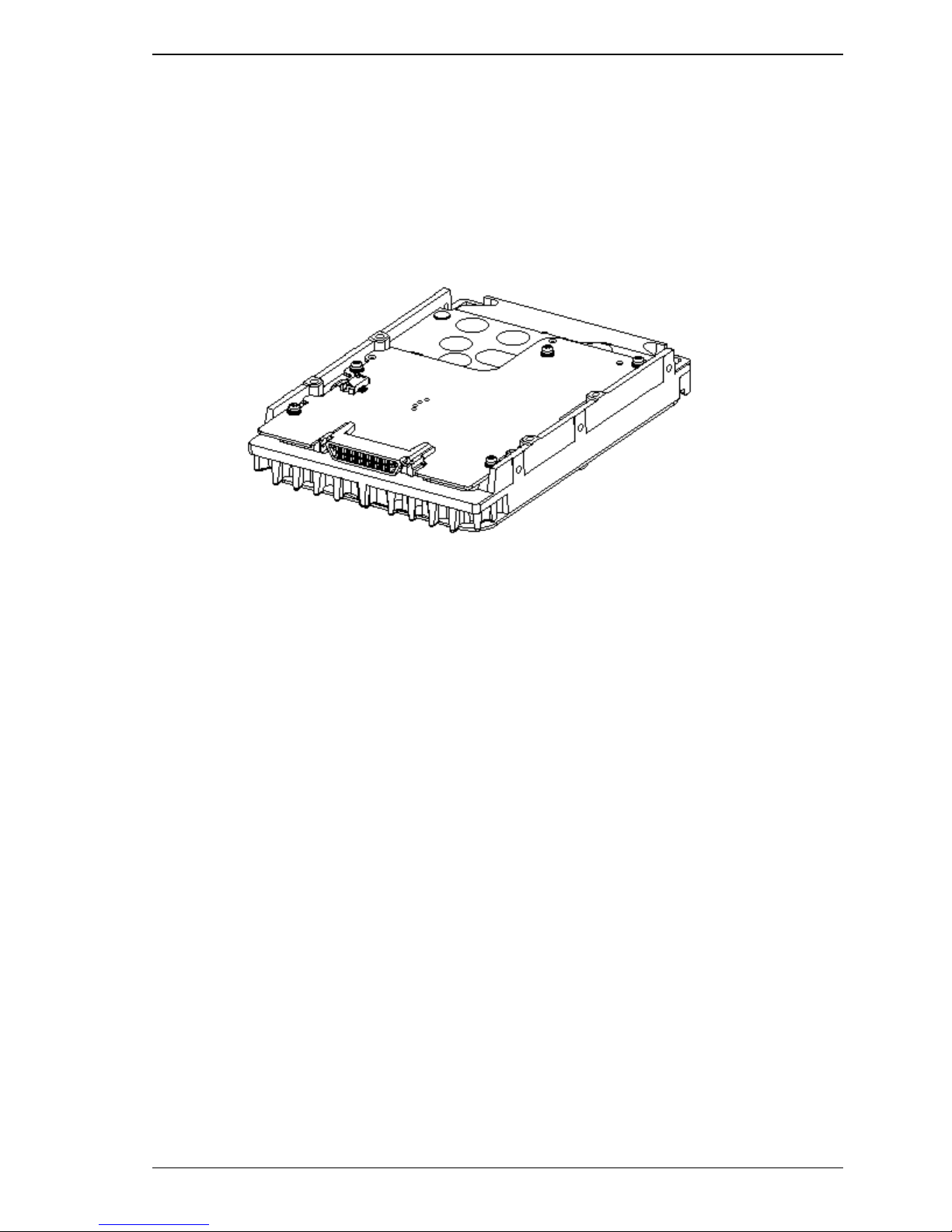
An outer view of the IDD is given in Figures 1.1. The IDD is composed of the disk, head, spindle
motor, mounted disk enclosure (DE) with actuator and air circulation filter, as well as read/write preamp with the print card unit (PCA) of the controller.
1.2 Hardware Structure
(1) Disks
The disks have an outer diameter of 84 mm (3.3 inch) outer diameter and 25 mm (0.98 inch) inner
diameter for MAN series. The disks are good for at least 20,000 contact starts and stops. Each
model contains following number of disks.
Figure 1.1 FC model outer view
MAN3735: 4
MAN3367: 2
C141-E133-02EN 1-5
Page 30
General Description
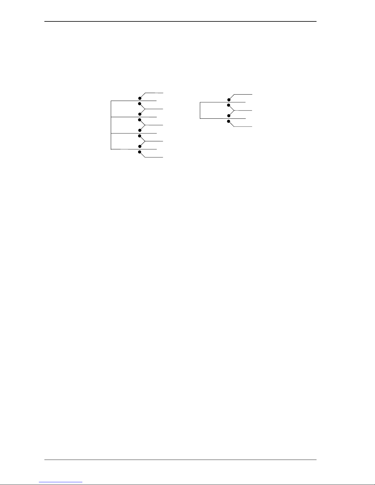
(2) Heads
The MR (Magnet - Resistive) of the CSS (contact start/stop) type heads are in contact with the disks
when the disks are not rotating, and automatically float when the rotation is started. Figure 1.2 shows
the configuration of disks and heads
(3) Spindle motor
The disks are rotated by a direct-drive hall-less DC motor. The motor speed is controlled by a
feedback circuit using the counter electromotive current to precisely maintain the specified speed.
(4) Actuator
MAN3735
0
1
2
3
4
5
6
7
Figure 1.2 Disk/head configuration
MAN3367
0
1
2
3
The actuator, which uses a rotary voice coil motor (VCM), consumes little power and generates little
heat. The heads at the end of the actuator arm is controlled and positioned via feedback of servo
information in the data.
The heads are positioned on the CCS zone over the disk when the power is off or the spindle motor is
stopped.
(5) Air circulation (recirculation filter, breather filter)
The disk enclosure (DE) configures a sealed room to keep out dust and other pollutants. The DE has
a closed-loop air recirculation system. Using the movement of the rotating disks, air is continuously
cycled through a filter. This filter will trap any dust generated inside the enclosure and keep the air
inside the DE contaminant free. To prevent negative pressure in the vicinity of the spindle when the
disks begin rotating, a breather filter is attached. The breather filter also equalizes the internal air
pressure with the atmospheric pressure due to surrounding temperature changes.
1-6 C141-E133-02EN
Page 31

(6) Read/write circuit
The read/write circuit utilizes a read channel mounted with a head IC that supports high-speed
transmission and an MEEPR4ML (Modified Enhanced Extended Partial Response Class 4 Maximum
Likelihood) modulation/demodulation circuit in order to prevent errors being triggered by external
noise and to improve data reliability.
(7) Controller circuit
The controller circuit uses LSIs to increase the reliability and uses a high speed microprocessing unit
(MPU) to increase the performance of the SCSI controller.
1.3 System Configuration
For the Fibre Channel, the ANSI standard defines Arbitrated Loop, Fabric, and Point-to-Point
technologies. The MAN-series disk drives support the Arbitrated Loop technology. Figure 1.3 gives
an example of the FC-AL system configuration.
1.3 System Configuration
Port B
Drive
(Node-2)
Port A
Port B
Drive
(Node-3)
Port A
Initiator
(Node-1)
Drive
(Node-4)
Port B
Port A
Port B
Port A
BC
BC
BC
BC
BC
BC
BC
BC
Figure 1.3 Example of FC-AL system configuration
Any device connected to the Fibre Channel is called a node. The nodes shown in Figure 3 represent
the initiator and individual disk drives. Each node has at least one port called an N_port. For FCAL, each port is called a Node-Loop port (NL_port).
The MAN-series disk drive has two ports, one of which is used for connections to an FC-AL. A
maximum of 126 NL_ports can be connected to a single port.
C141-E133-02EN 1-7
Page 32

General Description
(1) Loop configuration
A port embedded with sending and receiving circuits uses differential signals to send and receive data
on electric signal lines. A pair of signal lines is called a link. Since signals are sent in one direction
on a link, the links in a system must be connected to form a loop. The FC-AL interface sends and
receives data via nodes on the loop. Therefore, if a node connected to a loop is powered off or the
interface signals of a node cannot be sent or received correctly, the loop does not work normally. A
common solution preventing this problem from occurring is to add a port bypass circuit on the back
plane of the system. BC in Figure 1.3 indicates the port bypass circuit.
(2) Node addressing
A specific device number called a SEL ID is assigned to each node on a Fibre Channel loop. The
combination of signal levels on the back plane is used to define the SEL ID of a disk drive. The
signal levels are se nt on the seven signals (from SEL_0 to SEL_6) from CN1, which serves as an
SCA interface connector. SEL_6 is the most significant bit (MSB), having a bit weight of the sixth
power of 2, and SEL_0 is the least significant bit (LSB), having a bit weight of the zeroth power of 2.
Any number from 0 (X’00) to 125 (X’7D’) can be assigned as the SEL ID of a disk drive.
1-8 C141-E133-02EN
Page 33

CHAPTER 2 Specifications
2.1 Hardware Specifications
This chapter describes specifications of the IDD.
2.1 Hardware Specifications
2.1.1 Model name and part number
Each model has a different recording capacities and interface connector type when shipped. (See
Appendix C for the model name (type) and product number.)
The data format can be changed by reinitializing with the user's system.
C141-E133-02EN 2-1
Page 34

Specifications
2.1.2 Function specifications
Table 2.1 shows the function specifications of the IDD.
Table 2.1 Function specifications
Item
MAN3735 series MAN3367 series
Specification
Formatted capacity/device (*1) 73.49 GB 36.74 GB
Number of disks 4 2
Number of heads 8 4
Number of cylinders (*2) 29,902 29,950
Formatted capacity/track (B) 230,400 to 377,344
Number of rotations min-1 (rpm) 10,025±0.2%
Average latency time 2.99 msec
Seek time (*3)
(Read/Write)
Start/stop time
(*4)
Track to Track
Average
Full stroke
Start time
Stop time
0.4 ms/0.6 ms
4.5 ms/5.0 ms
11.0 ms/12.0 ms
30 s typ. (60 s max.)
30 s typ.
Recording mode 32/34 MEEPRML
External
dimensions
Height:
Width:
Depth:
25.4 mm
101.6 mm
146.0 mm
Weight (max) 0.75 kg
Power consumption (*5) 12.5 W 10.5 W
Interface Cable length: 30 m max
Data
Disk drive
52.0 to 84.1 MB/s
transfer
rate (*10)
FC-AL 212.5 MB/s max.
Logical data block length (*11) 512 to 528 byte (Fixed length)
FC-PLDA (NCITS TR-19),
Command specification
FC-PH (ANSI X3.230-1994), FC-PH-2 (ANSI X3.297-1996),
FC-AL (ANSI X3.272-199X), SCSI-FCP (ANSI X3.269-199X)
Data buffer 8 MB FIFO ring buffer
Acostic noise (Ready) 3.9 bels 3.6 bels
(*1)
The formatted capacity can be changed by changing the logical block length and using spare sector
space. See Chapter 3 for the further information. The formatted capacity listed in the table is an
estimate for 512 bytes per sector.
(*2)
The number of user cylinders indicates the max., and includes the alternate cylinder. The number of
user cylinders and alternate cylinders can be specified at format of the IDD.
(*3)
The positioning time is as follows:
2-2 C141-E133-02EN
Page 35

[
ms
]
Seek time
2.1 Hardware Specifications
Seek Difference [1024 Cyl/div]
(*4)
(*5)
The start time is the time from power on or start command to when the IDD is ready, and the stop
time is the time for disks to completely stop from power off or stop command.
This value indicates at ready mode.
C141-E133-02EN 2-3
Page 36

Specifications
2.1.3 Environmental specifications
Table 2.2 lists environmental and power requirements.
Table 2.2 Environmental/power requirements
Temperature
(*1)
Relative
humidity
(above sea
level)
Power
requirements
Input power
(*5)
Item
MAN3735 series MAN3367 series
Specification
Operating 5 to 50°C
Non-operating –10 to 60°C
Transport (within a week) –40 to 60°C
DE surface temperature at
operating
5 to 55°C
Gradient 15°C/h or less
Operating 20 to 80%RH
Non operating 20 to 80%RH
Transport (within a week) 5 to 90%RH
Maximum wet bulb
temperature
29°C (no condensation)
Operating (*3) 0.3 mm (5 to 20Hz)/9.8 m/s2 (1G) (20 to 300 Hz) or less
Non-operating (*4) 3.1 mm (5 to 20Hz)/49m/s2 (5G) (20 to 300Hz) or lessVibration (*2)
Transport (packaged) 3.1 mm (5 to 20Hz)/49m/s
2
(5G) (20 to 300Hz) or less
Operating 637.4m/s2 (65G) (2 ms)
Non-operating 1961.3m/s2 (200G) (2 ms)Shock (*2)
Transport (packaged) 1961.3m/s
2
(200G) (2 ms)
Operating –60 m to 3,000 mAltitute
Non-operating –60 m to 12,000 m
+12 VDC
±5%
Ready
(Average)
0.6 A 0.45 A
Peak within
100 µs at
3.0 A
spin-up
Random
W/R
(about 80
0.9 A 0.7 A
IOPS)
+5 VDC
±5%
Ready
(Average)
0.9 A
Random
W/R
(about 80
1.2 A
IOPS)
Ripple (*6) +5 V/+12 V 250 mVp-p
2-4 C141-E133-02EN
Page 37

2.1 Hardware Specifications
(*1)
(*2)
For detail condition, see Section 4.1.
Vibration applied to the drive is measured at near the mounting screw hole on the frame as much as
possible.
(*3)
(*4)
At random seek write/read and default on retry setting with log sweep vibration.
At power-off state after installation
Vibration displacement should be less than 2.5 mm.
(*5)
(*6)
Input voltages are specified at the connector.
High frequency noise is less than 100 mVp-p.
2.1.4 Error rate
Errors detected during initialization and replaced by alternate block assignments are not included in
the error rate. Data blocks to be accessed should be distributed over the disk medium equally.
(1) Unrecoverable error rate
Errors which cannot be recovered within 63 retries and ECC correction should not exceed 1 per 10
bits.
15
Data loss
For MAN series, Reed Solomon codes are applied for their ECC. The
sector-data is divided into 6 interleaving sectors, and ECC is
performed in each sector where the maximum number of errors (up to
5 byte) can be corrected. [Total maximum byte: 5 byte
interleave) = 30 byte]
If the error of read sector keeps allowable error byte number,
correction is performed. However, if error byte exceeds its allowable
number, correction may not be performed properly.
(2) Positioning error rate
Positioning errors which can be recovered by one retry should be 10 or less per 10
2.1.5 Reliability
(1) Mean Time Between Failures (MTBF)
MTBF of the IDD during its life time is 1,2000,000 hours (operating: 24 hours/day, 7 days/week
average DE surface temperature: 40°C or less).
CAUTION
×
6 (
8
seeks.
C141-E133-02EN 2-5
Page 38

Specifications
Note:
The MTBF is defined as:
Operating time (hours) at all field sites
MTBF=
The number of equipment failures from all field sites
Failure of the equipment means failure that requires repair, adjustments, or replacement.
Mishandling by the operator, failures due to bad environmental conditions, power trouble, host
system trouble, cable failures, or other failures not caused by the equipment are not considered.
(2) Mean Time To Repair (MTTR)
MTTR is the average time taken by a well-trained service mechanic to diagnose and repair a drive
malfunction. The drive is designed for a MTTR of 30 minutes or less.
(3) Service life
The service life under suitable conditions and treatment is as follows.
The service life is depending on the environment temperature. Therefore, the user must design the
system cabinet so that the average DE surface temperature is as possible as low.
DE surface temperature: 40°C or less 5 years
•
DE surface temperature: 41°C to 45°C 4.5 years
•
DE surface temperature: 46°C to 50°C 4 years
•
DE surface temperature: 51°C to 55°C 3.5 years
•
DE surface temperature: 56°C and more Strengthen cooling power so that DE surface
•
temperature is 55°C or less.
Even if the IDD is used intermittently, the longest service life is 5 years.
Note:
The "average DE surface temperature" means the average temperature at the DE surface
throughout the year when the IDD is operating.
2-6 C141-E133-02EN
Page 39

(4) Data security at power failure
Integrity of the data on the disk is guaranteed against all forms of DC power failure except on blocks
where a write operation is being performed. The above does not applied to formatting disks or
assigning alternate blocks.
2.1 Hardware Specifications
C141-E133-02EN 2-7
Page 40

This page is intentionally left blank.
Page 41

CHAPTER 3 Data Format
3.1 Data Space
3.2 Logical Data Block Addressing
3.3 Defect Management
This chapter explains data space definition, logical data block addressing, and defect management on the IDD.
3.1 Data Space
The IDD manages the entire data storage area divided into the following three data spaces.
User space: Storage area for user data
•
Internal test space: Reserved area for diagnostic purposes
•
System space: Area for exclusive use of IDD itself
•
The user space allows a user access by specifying data. These space can be accessed with the logical
data block addressing method described in Section 3.2. The internal test space is used by Read/write
test of self-diagnostics test, but user can’t use direct access. The system space is accessed inside the
IDD at power-on or during the execution of a specific command, but the user cannot directly access
the system space.
3.1.1 Cylinder configuration
The IDD allocates cylinders to the user space, Internal test space, and system space. Figure 3.1 is the
cylinder configuration.
Spare areas (alternate areas) for defective sectors are provided in the user space. Several sectors in
the last track of one cylinder and several cylinders (alternate cylinders) in the user space are allocated
as alternate areas according to the user's assignment (MODE SELECT command). See Subsection
3.1.2 for details.
C141-E133-02EN 3-1
Page 42

Data Format
Cylinder –85
to
Cylinder –78
Internal test cylinder
Internal test space
~~
~~
Cylinder –73
to
Cylinder –4
SAS69
•
SA0
System space
~~
~~
Cylinder 0
Cylinder 1
••
•
n–2
n–1
n
n = MAN3735FC series: 29,902
MAN3367FC series: 29,950
Note: Spare sectors on the last track in each cylinder are not necessarily placed at the end of the track
because of a track skew or a cylinder skew. (Details are explained in Subsection 3.1.3.)
Apart from the above logical configuration, the IDD intends to increase the storage capacity by
dividing all cylinders into several zones and changing a recording density of each zone. Tables 3.1 to
3.3 show the zone layout and the track capacity.
Primary Cylinder 0
to
Primary Cylinder (n–1)
Spare sector for each cylinder
Figure 3.1 Cylinder configuration
User space
~~
•
3-2 C141-E133-02EN
Page 43

3.1 Data Space
Table 3.1 Zone layout and track capacity
Cylinder
Zone
MAN3735FC series MAN3367FC series
0 0 - 500 503,342 737
1 501 - 2,301 485,746 720
2 2,302 - 4,102 485,746 720
3 4,103 - 5,983 476,708 696
4 5,984 - 7,884 464,618 680
5 7,885 - 9,885 448,818 660
6 9,886 - 11,886 438,224 640
7 11,887 - 13,307 431,162 630
8 13,308 - 15,108 420,030 612
9 15,109 - 17,109 404,290 600
Byte/track Sector/track
10 17,110 - 18,770 395,791 576
11 18,771 - 20,511 383,641 560
12 20,512 - 22,452 368,080 540
13 22,453 - 23,993 356,170 520
14 23,994 - 25,314 346,713 504
15 25,315 - 26,415 339,292 492
16 26,416 - 28,276 323,790 480
17 28,277 - 29,901 28,277 - 29,949 311,162 450
Note: When the logical data block length is 512 bytes, the sector/track capacity indicates above amount
(1) User space
The user space is a storage area for user data. The data format on the user space (the length of data
block and the number of data blocks) can be specified with the MODE SELECT or MODE SELECT
EXTENDED command.
The default value of cylinders in the user space is MAN3735 series = 29,902, MAN3367 series =
29,950. These also equal the maximum cylinders number for each series. The user can also specify
the number of logical data blocks to be placed in the user space with the MODE SELECT or MODE
SELECT EXTENDED command. When the number of logical data blocks is specified, as many
cylinders as required to place the specified data blocks are allocated in the user space.
C141-E133-02EN 3-3
Page 44

Data Format
A number staring with 0 is assigned to each cylinder required in the user space in ascending order. If
the number of cylinders do not reach the maximum, the rest of the cylinders will not be used.
Always one alternate cylinders can be established in the user space. Alternate cylinders will be used
for alternate blocks when primary cylinders in the user space are used up. See Subsections 3.1.2 and
3.3.2 for details.
(2) Internal test space
The Internal test space is an area for diagnostic purposes only and its data block length is always
512KByte. The Internal test space consists of 8 cylinders and outer-host cylinder is always assigned.
The user cannot change the number of cylinders in the Internal test space or their positions.
(3) System space
The system space is an area for exclusive use of the IDD itself and the following information are
recorded.
Defect list (P list and G list)
•
MODE SELECT parameter (saved value)
•
Statistical information (log data)
•
Controller control information
•
The above information is duplicated in several different locations for safety.
Note:
The system space is also called SA space.
3.1.2 Alternate spare area
The alternate spare area consists of the last track of each cell in the user space and an alternate
cylinder allocated to the last cylinder of each zone.
The spare area in each cylinder is placed at the end of the last track as shown in Figure 3.2. These
spare sectors are located in the end of the track logically, not necessarily located at the end physically
because of track skew or cylinder skew. (Details are explained on Subsection 3.1.3.)
Size can be specified by the MODE SELECT command.
The number of spare sectors per cylinder can be specified exceeding 32. The default for the spare
sectors number is 12.
3-4 C141-E133-02EN
Page 45

Cell
3.1 Data Space
Note: This drive manages alternate spare areas for each cell, which is a set of cylinders. The
default value for the number of cylinders is four.
Figure 3.2 Spare area in cell
An alternate cylinder is used when spare sectors in a cell are used up or 0 is specified as the number
of spare sectors in a cell. 1 cylinder at the end of each zone of the user space is allocated as alternate
cylinders as shown in Figure 3.3.
The user space and the CE space share the alternate cylinders.
Note:
Zero cannot be specified for both the number of spare sectors in each cylinder and the number of
alternate cylinders.
3.1.3 Track format
(1) Physical sector allocation
Figure 3.4 shows the allocation of the physical sectors in a track. The length in bytes of each
physical sector and the number of sectors per track vary depending on the logical data block length.
The unused area (G4) exists at the end of the tra ck in formats with most logical data block lengths.
Zone
Figure 3.3 Alternate cylinder
The interval of the sector pulse (length of the physical sector) is decided by multiple of 40MHz free
running frequency. This clock is not equal to the interval of the byte clock for each zone. T herefor e,
the physical sector length cannot be described with a byte length.
C141-E133-02EN 3-5
Page 46

Data Format
(2) Track skew and cylinder skew
To avoid waiting for one turn involved in head and cylinder switching, the first logical data block in
each track is shifted by the number of sectors (track skew and cylinder skew) corresponding to the
switching time. Figure 3.5 shows how the data block is allocated in each track.
5.99 msec
Servo frame
n = 305 (zone 0) ~ 494 (zone 17)
Figure 3.4 Track format
At the head switching location in a cylinder, the first logical data block in track t + 1 is allocated at
the sector position which locates the track skew behind the sector position of the last logical data
block sector in track t.
At the cylinder switching location, like the head switching location, the first logical data block in a
cylinder is allocated at the sector position which locates the cylinder skew behind the last logical
sector position in the preceding cylinder. The last logical sector in the cylinder is allocated when
formatting, and is an unused spare sect or.
3-6 C141-E133-02EN
Page 47

3.1 Data Space
The number of physical sectors (track skew factor and cylinder skew factor) corresponding to the
skew time varies depending on the logical data block length because the track skew and the cylinder
skew are managed for individual sectors. The IDD automatically determines appropriate values for
the track skew factor and the cylinder skew factor according to the specified logical data block
length. The value can be read out by the MODE SENSE or MODE SENSE EXTENDED command
after the track has been formatted.
3.1.4 Sector format
Each sector on the track consists of an ID field, a data field, and a gap field which separates them.
Figure 3.6 gives sector format examples.
Figure 3.5 Track skew/cylinder skew
C141-E133-02EN 3-7
Page 48

Data Format
SCT
SCT
G1
PLO
SyncG1
PLO
Sync
SM1
SM1
DATA1
DATA1
SM2 BCRCDATA2 ECC
Servo
SM2 DATA3
PAD
G2
G1 6 bytes
G2 12 bytes
G3 8 bytes
PLO Sync 36 bytes
SM1 4 bytes
SM2 2 bytes
BCRC 4 bytes
ECC 60 bytes
PAD 6 bytes
DATA1 24 bytes
DATA2 488 bytes
DATA3
DATA4 (464 – n) bytes
SCT
PAD
G2
PLO
SM1
SyncG1
n bytes (0≤n≤464,
n is a multiple of 4.)
DATA1 SM2 DATA4
BCRC ECC
PAD
SCT
G3
Each sector on the track consists of the following fields:
(1) Gaps (G1, G2, G3)
The gap length at the time of formatting (initializing) is listed in Figure 3.6. No pattern is written on
the gap field.
(2) PLO Sync
In this field, pattern X'00' in the length in bytes listed in Figure 3.6 is written.
(3) Sync Mark (SM1, SM2)
In this field, special pattern in the length in bytes listed in Figure 3.6 is written. This special pattern
indicates the beginning of the data field.
(4) Da ta field (DATA1-DATA4)
User data is stored in the data field of the sector. The length of the data field is equal to that of the
logical data block which is specified with a parameter in the MODE SELECT command. Any even
number between 512 and 528 bytes can be specified as the length.
Figure 3.6 Sector format
3-8 C141-E133-02EN
Page 49

(5) BCRC
It is a 4-byte error detection code. Errors in the ID field. Single burst errors with lengths of up to 32
bits for each logical block can be detected.
(6) ECC
This is the 60-byte code that allows detection and correction of errors in the data field, which is
capable of correcting the single burst error up to 240 bits max. on the fly.
(7) PAD
A specified length of x‘00’ pattern shown in Figure 3.6 is written in this field. This field includes the
variation by rotation and circuit delay till reading/writing.
3.1.5 Format capacity
The size of the usable area for storing user data on the IDD (format capacity) varies according to the
logical data block or the size of the spare sector area. Table 3.2 lists examples of the format capacity
when the typical logical data block length and the default spare area are used. The following is the
general formula to calculate the format capacity.
3.1 Data Space
[Number of sectors of each zone] = [number of sectors per track × number of tracks (heads) –
number of alternate spare sectors per cylinder] × [number of cylinders in the zone]
[Formatted capacity] = [total of sectors of all zones] – [number of sectors per track in last zone
number of tracks (heads) × number of alternate cylinders] ÷ [number of physical sectors in logical
block] × [logical data block length]
The following formula must be used when the number of logical data blocks are specified with the
parameter in the MODE SELECT or MODE SELECT EXTENDED command.
[Format capacity] = [logical data block length] × [number of logical data blocks]
The logical data block length, the maximum logical block address, and the number of the logical data
blocks can be read out by a READ CAPACITY, MODE SENSE, or MODE SENSE EXTENDED
command after initializing the disk medium.
×
C141-E133-02EN 3-9
Page 50

Data Format
Table 3.2 Format capacity
Model Data heads Data block length User blocks Format capacity (GB)
MAN3735FC series 8 143,550,456 73.49
MAN3367FC series 4
Note:
Total number of spare sectors is calculated by adding the number of spare sectors in each primary
cylinder and the number of sectors in the alternate cylinders.
3.2 Logical Data Block Addressing
Independently of the physical structure of the disk drive, the IDD adopts the logical data block
addressing as a data access method on the disk medium. The IDD relates a logical data block address
to each physical sector at formatting. Data on the disk medium is accessed in logical data block
units. The INIT specifies the data to be accessed using the logical data block address of that data.
The logical data block addressing is a function whereby individual data blocks are given addresses of
serial binaries in each drive.
512
71,771,688 36.74
(1) Block address of user space
The logical data block address number is consecutively assigned to all of the data blocks in the user
space starting with 0 to the first data block.
The IDD treats sector 0, track 0, cylinder 0 as the first logical data block. The data block is allocated
in ascending order of addresses in the following sequence (refer to Figure 3.5):
1) Logical data blocks are assigned in ascending order of sector number in the same track.
2) Subsequent logical data blocks are assigned to sectors in every track except the last track in
ascending order of track number in the same cylinder. Within the same track, logical data blo cks
are assigned in the same way as step 1).
3) Subsequent logical data blocks are assigned to sectors in every track except the last track in
ascending order of track number in the same cell. Within the same track, logical data blocks are
assigned in the same way as step 1).
4) For the last track in the same cell, subsequent logical data blocks are assigned to sectors other
than spare sectors in ascending order of sector number.
5) After blocks have been assigned in the same cell according to steps 1) to 4), subsequent logical
data blocks are assigned in ascending order of cell number in the same way as in steps 1) to 4).
Logical data blocks are assigned starting from track 0 in the next cell until the last cylinder
(immediately preceding the alternate cylinder n-1 shown in Figure 3.1) of the zone except
alternate cylinders in cells in the user space.
3-10 C141-E133-02EN
Page 51

When the logical data block is allocated, some sectors (track skew and cylinder skew) shown in
Figure 3.5 are provided to avoid waiting for one turn involving head and cylinder switching at the
location where the track or the cylinder is physically switched.
See Subsection 3.3.2 for defective/alternate block treatment and the logical data block allocation
method in case of defective sectors exist on the disk.
(2) Alternate area
Alternate areas in the user space (spare sectors in the cylinder and alternate cylinders) are not
included in the above logical data block addresses. Access to sectors which are allocated as an
alternate block in the alternate area is made automatically by means of IDD sector slip treatment or
alternate block treatment (explained in Subsection 3.3.2), so the user does not have to worry about
accessing the alternate area. The user cannot access with specifying the data block on the alternate
area explicitly.
3.3 Defect Management
3.3.1 Defect list
Information of the defect location on the disk is managed by the defect list. The following are defect
lists which the IDD manages.
3.3 Defect Management
P list (Primary defect list): This list consists of defect location information available at the disk
•
drive shipment and is recorded in a system space. The defects in this list are permanent, so the
INIT must execute the alternate block allocation using this list when initializing the disk.
D list (Data defect list): This list consists of defect location information specified in a FORMAT
•
UNIT command by the INIT at the initialization of the disk. This information is recorded in the
system space of the disk drive as the G list. To execute the alternate block allocation, the
FORMAT UNIT command must be specified.
G list (Growth defect list): This list consists of defective logical data block location information
•
specified in a REASSIGN BLOCKS command by the INIT, information on defective logical data
blocks assigned alternate blocks by means of IDD automatic alternate block allocation,
information specified as the D list, and information generated as the C list. They are recorded in
the system space on the disk drive.
The INIT can read out the contents of the P and G lists by th e READ DEFECT DATA com m and.
3.3.2 Alternate block allocation
The alternate data block is allocated to a defective data block (= sectors) in defective sector units by
means of the defect management method inside the IDD.
The INIT can access all logical data blocks in the user space, as long as there is no error.
Spare sectors to which alternate blocks are allocated can be provided in either "spare sectors in a
cylinder" or "alternate cylinders". See Subsection 3.1.2 for details.
The INIT can specify the size and area for spare sectors by the MODE SELECT command at the
time of the initialization of the disk.
C141-E133-02EN 3-11
Page 52

Data Format
Both of the following are applicable to the alternate block allocation.
Sector slip treatment: Defective sectors are skipped and the logical data block corresponding to
•
those sectors is allocated to the next physical sectors. This treatment is made on the same
cylinder as the defective sector's and is effective until all spare sectors in that cylinder are used
up.
Alternate sector treatment: The logical data block corresponding to defective sectors is allocated
•
to unused spare se ctors in the same cylinder or unused spare sectors in the alternate cylinder.
The alternate block allocation is executed by the FORMAT UNIT command, the REASSIGN
BLOCKS command, or the automatic alternate block allocation. Refer to OEM Manual–Fibre
Channel Specifications–for details of specifications on these commands. The logical data block is
allocated to the next physically continued sectors after the above sector slip treatment is made. On
the other hand, the logical data block is allocated to spare sectors which are not physically
consecutive to the adjacent logical data blocks. If a command which processes several logical data
blocks is specified, the IDD processes those blocks in ascending order of logical data block.
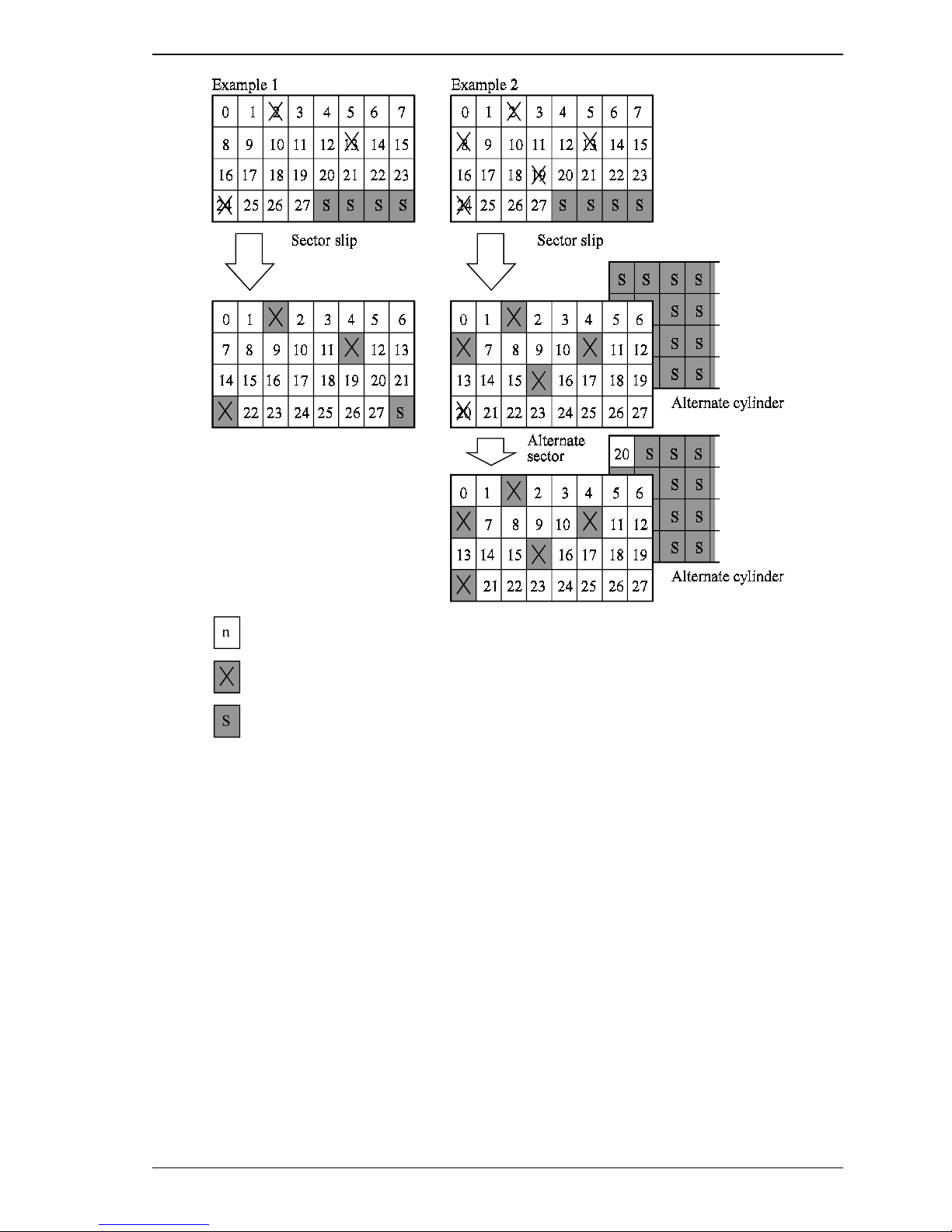
(1) Alternate block allocation during FORMAT UNIT command execution
When the FORMAT UNIT command is specified, the allocation of the alternate block to those
defective sectors included in the specified lists (P, G, or D) is continued until all spare sectors in the
same cylinder are used up . W hen they are use d up , unused spar e se ctor s in the a lter nate cylinder ar e
allocated to the subsequent sectors in the cylinder by means of alternate sector treatment. Figure 3.7
is examples of the alternate block allocation during the FORMAT UNIT command execution.
3-12 C141-E133-02EN
Page 53
3.3 Defect Management
: n represents a logical data block number
: Defective sector
: Unused spare sector
Figure 3.7 Alternate block allocation by FORMAT UNIT command
If the data block verifying operation (certification) is not permitted (DCRT flag = 0) in the FORMAT
UNIT command, the IDD checks all initialized logical data blocks by reading them out after the
above alternate block allocation is made to initialize (format) the disk. If a defective data block is
detected during the check, the IDD allocates the alternate block to the defective data block. This
alternate block allocation is made by means of alternate sector treatment only like processing by the
REASSIGN BLOCKS command even if unused spare sectors exists i n t he same cylinder.
C141-E133-02EN 3-13
Page 54

Data Format
(2) Alternate block allocation by REASSIGN BLOCKS command
When the REASSIGN BLOCKS command is specified, the alternate block is allocated to the
defective logical data block specified by the initiator by means of alternate sector treatment. If there
are unused spare sectors in the same cylinder as the specified defective logical data block, the
alternate block is allocated to these unused spa re sectors. However, the alternate block is allocate d to
unused spare sectors in the alternate c ylind er when all spare sector s in the cylinder are used up.
Figure 3.8 is examples of the alternate block allocation by the REASSIGN BLOCKS command.
: n represents a logical data block number
: Defective sector
: Unused spare sector
Figure 3.8 Alternate block allocation by REASSIGN BLOCKS command
3-14 C141-E133-02EN
Page 55

(3) Automatic alternate block allocation
Automatic alternate block allocation at read operation
•
If the ARRE flag in the MODE SELECT parameter permits the automatic alternate block allocation,
the IDD automatically executes the alternate block allocation and data duplication on the defective
data block detected during the READ or READ EXTENDED command. This allocation method is
the same as with the REASSIGN BLOCKS command (alternate sector treatment).
Automatic alternate block allocation at write operation
•
If the AWRE flag in the MODE SELECT parameter permits the automatic alternate block allocation,
the IDD executes reassign processing to all the existing sectors in the servo frame where offtrack
error occurred during WRITE or WRITE EXTENDED or WRITE AND VERIFY command
processing and in the next servo frame. After completing reassignment, WRITE or WRITE
EXTENDED command processing is successively executed for the following sectors.
Automatic alternate block allocation is made only once during the
execution of one command. If second defective block is detected, the
alternate block assignment processing for the first defective block is
executed but the alternate block assignment processing for the second
one is not executed and the command being executed terminates.
However, the initiator can recover the twice error by issuing the same
command again.
3.3 Defect Management
IMPORTANT
When an error is detected in a data block in the data area, recovery
data is rewritten and verified in automatic alternate block allocation
during the execution of the READ or READ EXTENDED command.
Alternate block allocation will not be made for the data block if
recovery is successful.
Example: Even if the data error which is recoverable by the WRITE
LONG command is simulated, automatic alternate block
allocation will not be made fo r the data block.
C141-E133-02EN 3-15
Page 56

This page is intentionally left blank.
Page 57

CHAPTER 4 Installation Requirements
4.1 Mounting Requirements
4.2 Power Supply Requirements
4.3 Connection Requirements
This chapter describes the environmental, mounting, power supply, and connection requirements.
4.1 Mounting Requirements
4.1.1 External dimensions
Figures 4.1 show the external dimensions of the IDD and the positions of the holes for the IDD
mounting screws.
Note:
Dimensions are in mm.
C141-E133-02EN 4-1
Page 58

Installation Requirements
The value marked with (*) indicates the dimension between mounting holes on the bottom face.
4-2 C141-E133-02EN
Figure 4.1 External dimensions
Page 59

4.1.2 Mounting
The permissible orientations of the IDD are shown in Figure 4.2, and the tolerance of the angle is ±5°
from the horizontal plane.
(a) Horizontal –1 (b) Horizontal –2 (c) Vertical –1
4.1 Mounting Requirements
(d) Vertical –2 (e) Upright mounting –1 (f) Upright mounting –2
4.1.3 Notes on mounting
(1) Mounting frame structure
Special attention must be given to mount the IDD disk enclosure (DE) as follows.
a) Use the frame with an embossed structure, or the like. Mount the IDD with making a gap of
2.5 mm or more between the IDD and the frame of the system.
b) As shown in Figure 4.3, the inward projection of the screw from the IDD frame wall at the
corner must be 6.35 mm or less.
Direction of gravity
Figure 4.2 IDD orientations
c) Tightening torque of screw must be secured with 0.59N·m (6kgf·cm).
d) Impact caused by the electric driver must be within the device specifications.
C141-E133-02EN 4-3
Page 60

Installation Requirements
1
e) Must be handled on an anti-static mat.
6.35 or less
6.35 or less
Figure 4.3 Mounting frame structure
(2) Limitation of side-mounting
Mount the IDD using the 4 screw holes at the both ends on the both sides as shown in Figure 4.4. Do
not use the center hole by itself.
In case of using the center hole, it must be used in combination with 2 holes on both ends.
(Total 6 screws for 6 holes enclosed)
Holes for
mounting scre w
3
4
2
Holes for mounting screw
4-4 C141-E133-02EN
Center holes
Use four holes (No.1-4) to mount
Figure 4.4 Limitation of side-mounting
Page 61

(3) Limitation of bottom-mounting
Use all 4 mounting holes on the bottom face.
(4) Enviro nment al temperature
Temperature condition at installed in a cabinet is indicated with ambient temperature measured 3 cm
from the disk drive. At designing the system cabinet, consider following points.
Make a suitable air flow so that the DE surface temperature does not exceed 55°C.
•
Cool the PCA side especially with air circulation inside the cabinet. Confirm the cooling effect
•
by measuring temperature of specific ICs and the DE. These measurement results should be
within a criteria listed in Table 4.1.
Keeping the DE surface temperature at 40°C or lower, which is a condition for assuring an
•
MTBF of 1,200,000 hours, requires an air flow of 1.0 m/s.
Table 4.1 Surface temperature check point
No. Measurement point Criteria
1 Center of DE cover 55°C
2 Read channel LSI 90°C
3 VCM/SPM Driver 92°C
4 HDC 95°C
5 MPU 88°C
4.1 Mounting Requirements
4
5
Figure 4.5 Surface temperature measurement points
3
2
C141-E133-02EN 4-5
Page 62

Installation Requirements
(5) Service clearance area
The service clearance area, or the sides which must allow access to the IDD for installation or
maintenance, is shown in Figures 4.6.
[Surface P]
- Cable connection
[Surface R]
- Hole for mounting screw
[Surface Q]
- Hole for mounting screw
(6) Exter nal magnetic field
The drive should not be installed near the ferromagnetic body like a speaker to avoid the influence of
the external magnetic field.
(7) Leak magnetic flux
The IDD uses a high performance magnet to achieve a high speed seek. Therefore, a leak magnetic
flux at surface of the IDD is large. Mount the IDD so that the leak magnetic flux does not affect to
near equipment.
(8) Others
Seals on the DE prevent the DE inside from the dust. Do not damage or peel off labels.
Figure 4.6 Service clearance area
4-6 C141-E133-02EN
Page 63
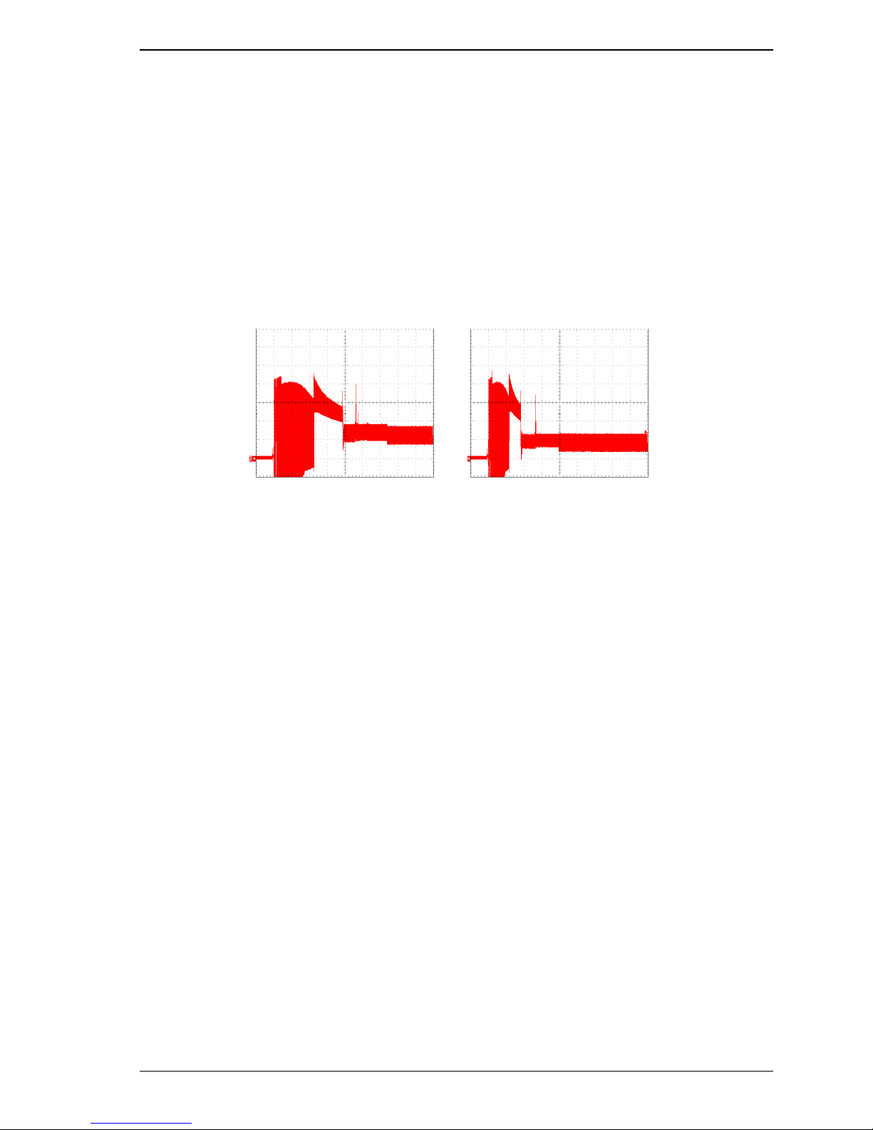
4.2 Power Supply Requirements
(1) Allowable input voltage and current
The power supply input voltage measured at the power supply connector pin of the IDD (receiving
end) must satisfy the requirement given in Subsection 2.1.3. (For other requirements, see Items (4)
below.)
(2) Current waveform (reference)
Figure 4.7 shows the waveform of +12 VDC.
MAN3735FC MAN3367FC
4.2 Power Supply Requirements
Current (500 mA/div)
Time (2
(3) Power on/off sequence
The order of the power on/off sequence of +5 VDC and +12 VDC, supplied to the IDD, does not
matter.
(4) Sequential starting of spindle motors
After power is turned on to the IDD, a large amount of current flows in the +12 VDC line when the
spindle motor rotation starts. Therefore, if more than one IDD is used, the spindle motors should be
started sequentially using one of the following procedures to prevent overload of the power supply
unit.
a) Issue START/STOP commands at more than 12-second intervals to start the spindle motors. For
details of this command specification, refer to Fibre Channel Interface Specifications.
b) Turn on the +12 VDC power in the power supply unit at more than 12-second intervals to start
the spindle motors sequentially.
/div)
sec
Figure 4.7 Current waveform (+12 VDC)
Current (500 mA/div)
Time (2 sec/div)
C141-E133-02EN 4-7
Page 64

Installation Requirements
(5) Noise filter
To eliminate AC line noise, a noise filter should be installed at the AC input terminal on the IDD
power supply unit. The specification of this noise filter is as follows:
Attenuation: 40 dB or more at 10 MHz
•
Circuit construction: T-configuration as shown in Figure 4 .8 is recommended.
•
Figure 4.8 AC noise filter (recommended)
4-8 C141-E133-02EN
Page 65

4.3 Connection Requirements
4.3.1 Connector
Figure 4.9 shows the locations of interface connector.
4.3 Connection Requirements
Interface connector (CN1)
(Including power supply connector)
4.3.2 Interface connector
The connector for the Fibre Channel Loop is an unshielded SCA-2 connector which has two 20pin rows spaced 1.27 mm (0.05 inch) apart. Figure 4.10 shows the connector. See Section B.1 in
Appendix B for signal assignments on the connector.
For details on the physical/electrical requirements of the interface signals, refer to Chapter 1 in
Fibre Channel Interface Specifications.
Figure 4.9 Connector location
C141-E133-02EN 4-9
Page 66
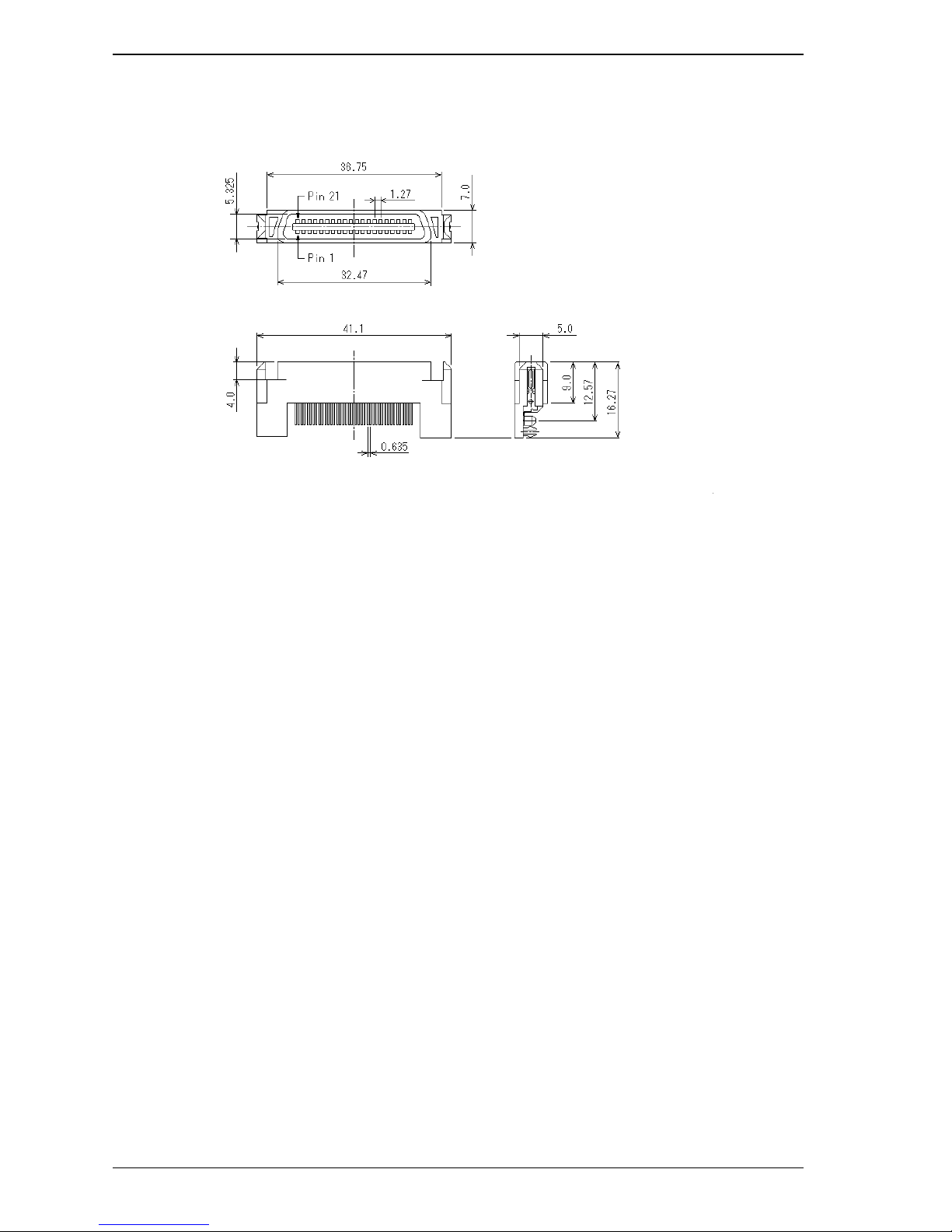
Installation Requirements
Figure 4.10 SCA2 type connector
4-10 C141-E133-02EN
Page 67

CHAPTER 5 Installation
5.1 Notes on Handling Drives
5.2 Setting
5.3 Mounting Drives
5.4 Dismounting Drives
5.5 Checking Operation after Installation and Preparing
the IDD for Use
5.6 Spare Disk Drive
This chapter describes the notes on handling drives, setting, mounting drives, confirming drive operations
after installation and preparation for use, and dismounting drives.
5.1 Notes on Handling Drives
The items listed in the specifications in Table 2.1 must be strictly observed.
(1) General notes
a) Do not give the drive shocks or vibrations exceeding the value defined in the standard because it
may cause critical damage to the drive. Especially be careful when unpacking.
b) Do not leave the drive in a dirty or contaminated environment.
c) Since static discharge may destroy the CMOS semiconductors in the drive, note the following
after unpacking:
Use an antistatic mat and body grounding when handling the drive.
•
Hold the DE when handling the drive. Do not touch PCAs except for setting.
•
Hot temperature
To prevent injury, do not handle the drive until after the device has cooled
sufficiently after turning off the power. The DE and LSI become hot during
operation and remain hot immediately after turning off the power.
CAUTION
C141-E133-02EN 5-1
Page 68

Installation
(2) Unpackaging
a) Use a flat work area. Check that the "This Side Up" sign side is up. Handle the package on soft
material such as a rubber mat, not on hard material such as a desk.
b) Be careful not to give excess pressure to the internal unit when removing cushions.
c) Be careful not to give excess pressure to the PCAs and interface connector when removing the
drive from the antistatic bag.
d) Do not remove the sealing label or cover of the DE and screws.
(3) Installation/removal/replacement
a) Do not attempt to connect or disconnect connections when power is on.
b) Do not move the drive when power is turned on or until the drive completely stops (for 30
seconds) after power is turned off.
c) Place and keep removed screws and other parts where they will not get lost or damaged.
d) Keep a record of all maintenance work for replacing.
(4) Packaging
a) Store the drive in an antistatic vinyl pack.
b) It is recommended to use the same cushions and packages as those at delivery. If those at
delivery cannot be used, use a package with shock absorption so that the drive is free from direct
shocks. In this case, fully protect the PCAs and interface connector so that they are not damaged.
c) Indicate "This Side Up" and "Handle With Care" on the outside of the package so that it is not
turned over.
(5) Delivery
a) When delivering the drive, provide packaging and do not turn it over.
b) Minimize the delivery distance after unpacking and avoid shocks and vibrations with cushions.
For the carrying direction at delivery, use one of the mount allowable directions in Subsection
4.1.2 (vertical direction is recommended).
(6) Storage
a) Provide vaporproof packaging for storage.
b) The storage environment must satisfy the requirements specified in Subsection 2.1.3 when the
drive is not operating.
c) To prevent condensation, avoid sudden changes in temperature.
5-2 C141-E133-02EN
Page 69

5.2 Setting
5.2.1 Loop ID setting
When setting the fibre channel loop ID, use SEL0 to SEL6 of interface connector CN1. IN bit
weighting, SEL6 corresponds to the MSB, SEL0 to the LSB, and 126 types of X'00' to X'7D' can be
specified as loop IDs.
5.2.2 Mode settings
(1) Motor start mode
The method for start control of the IDD spindle motor can be set in accordance with Table 5.1.
Table 5.1 Motor start mode
Setting
Signal name
Start_2/Mated Start_1/Mated Start mode
Connector pin
CN1-10 CN1-09
Open Open The drive is not connected to the system. The drive does not start the
spindle motor.
Open GND The drive is connected to the system. After recognizing the
connection, the drive starts the spindle motor upon receipt of a
START/STOP UNIT command.
GND Open The drive is connected to the system. After recognizing the
connection, the drive starts the spindle motor after a prescribed delay
time has elapsed.
GND GND T he drive is connected to the system. The driver starts the spindle
motor immediately after recognizing the connection.
5.2 Setting
Set the loop ID so that there are no duplicates between devices on the same
loop.
C141-E133-02EN 5-3
IMPORTANT
Page 70

Installation
5.3 Mounting Drives
5.3.1 Mounting procedures
Since mounting the drive depends on the system cabinet structure, determine the work procedures
considering the requirements specific to each system. The general mounting method and items to be
checked are shown below.
See Subsection 4.1 for the details of requirements for installing the IDD.
1) With a system to which an external operator panel is mounted, if it is difficult to access the
connector after the drive is mounted on the system cabinet, connect the external operator panel
cable before mounting the drive.
2) Fix the drive in the system cabinet with four mounting screws as follows:
The drive has 10 mounting holes (both sides: 3 × 2, bottom: 4). Fix the drive by using four
•
mounting holes of both sides or the bottom. (See Figure 4.6)
Use mounting screws whose lengths inside the drive mounting frame are 6.35 mm or less
•
when the screws are tightened (see Figure 4.3).
When mounting the drive, be careful not to damage parts on the PCAs.
•
3) Check to ensure that the DE is not touching the frame on the system side after tightening the
screws. At least 2.5mm of clearance is required between the DE and the frame. (Indicated in
Figure 4.3)
4) When an electric driver is in use, less than device specifications must be used.
5-4 C141-E133-02EN
Page 71

5.4 Dismounting Drives
Since the method and procedure for dismounting the disk drive for replacement of the drive, etc.
depends on the locker structure of the system, etc., the work procedure must be determined in
consideration of the requirements specific to the system. This section describes the general
procedure and notes on dismounting the drive.
Damage
1. When dismounting the drive which is mounted on the system while power is
supplied to it.
• The drive to be dismounted must be separated from the loop.
Dismounting the drive which is not separated from the loop may cause
an unexpected error.
• If the drive is not separated from the loop, issue an LPB to the drive
from the initiator in a primitive sequen ce of the order set.
• It is recommended to stop the spindle motor prior to this loop
separation operation. The spindle motor can be stopped by a
START/STOP command. It takes about 30 seconds for the spindle
motor to stop completely.
• Then, dismount the drive using the drive mounting/dismounting
mechanism, etc. of the system. If the drive is dismounted while the
spindle motor is running, special care is required to avoid excessive
vibration or shock to the drive. It is recommended to stop the operation
once the SCA connector breaks off contact and wait until the spindle
motor stops (about 30 seconds) before dismount the drive.
• When storing or transporting the drive, put it in an antistatic bag.
(Shown in Section 5.1).
5.4 Dismounting Drives
CAUTION
2. When dismounting the drive which is mounted on the system while power is
not supplied to it.
• Do not move the drive until the drive stops completely (about 30
seconds if the spindle motor was stopped by a START/STOP UNIT
command, and about 30 seconds after powering-off when the power
was simply turned off).
• Then, dismount the drive using the drive mounting/dismounting
mechanism, etc. of the system.
• When storing or transporting the drive, put it in an antistatic bag.
(Shown in Section 5.1).
C141-E133-02EN 5-5
Page 72

Installation
5.5 Checking Operation after Installation and Preparing the IDD for Use
5.5.1 Checking initial operation
This section explains how to check operation after power is turned on. Since the initial operation of
an IDD differs depending on the settings of the motor start mode, check the following initial
operations according to the motor start mode set during installation.
(1) Initial operation if the settings have been specified so that turning power on automatically starts
rotating the motor
a) When power is turned on, the Active LED blinks and the IDD starts the initial self-diagnosis.
b) If the initial self-diagnosis detects a problem, the IDD sends the Fault LED Out signal to the
interface connector, as specified by SFF8045.
Remark: The spindle motor may or may not start rotating in this stage.
c) If the IDD is in idle mode, the Active LED remains lit. (When the initiator accesses the IDD, the
LED goes off and then goes on again at the end of the processing requested by the initiator.)
(2) Initial operation if the settings have been specified so that the START/STOP UNIT command is used
to start rotating the motor
a) When power is turned on, the Active LED goes on momentarily and the IDD starts the initial
self-diagnosis.
b) If the initial self-diagnosis detects a problem, the IDD sends the Fault LED Out signal to the
interface connector, as specified by SFF8045.
c) The spindle motor does not rotate until the START/STOP UNIT command is received. The
initiator is required to use the procedure described in Section 5.5.2 to send the START/STOP
UNIT command.
d) About 60 seconds after the START/STOP UNIT command is received, the disk drive enters the
READY state. The IDD then starts reading system information from the system space on disks.
e) The Active LED goes off while the command is being executed.
(3) Take the following actions if a problem occurs:
a) Check if all cables are correctly connected.
b) Check if the power supply voltage is correct. (Measure the voltage at the power connector on the
IDD.)
5-6 C141-E133-02EN
Page 73

5.5 Checking Operation after Installation and Preparing the IDD for Use
c) Continuous sending of the Fault LED Out signal to the interface connector indicates the initial
self-diagnosis has detected a problem. In this event and if the situation allows, sense data should
be obtained by issuing the REQEUST SENSE command from the initiator (host system). Sense
data is information required for troubleshooting.
The Active LED goes off while the IDD command is being executed. For
some commands, however, since the Active LED goes off for only a fraction
of a second, the Active LED looks like it flashes or remains lit.
5.5.2 Checking connection
When the initial operation is checked normally after power is turned on, check that the IDD is
connected to the loop from the host system. Although checking the connection depends on the
structure of the host system, this section describes the general procedures.
(1) Checking procedure
IMPORTANT
Issuing the commands and determining the end status depends on the start mode of the spindle motor
and UNIT ATTENTION report mode (specified with setting terminal). Figure 5.1 shows the
recommended checking procedure for the mode that the motor starts when power is turned on.
Figure 5.2 shows for the mode that the motor starts by the START/STOP command. In these
recommended checking procedures, following items are checked.
Note:
Following steps a) to e) correspond to a) to e) in Figures 5.1 and 5.2.
a) Issue the TEST UNIT READY command and check that the IDD is connected correctly to
the loop and the initial operation after power is turned on ended normally. The command
issue period of the TEST UNIT READY command shall be more than 20 ms.
b) To control starting of the spindle motor from the host system, issue the START/STOP
UNIT command to start the spindle motor.
c) Check the loop operations with the WRITE BUFFER and READ BUFFER commands.
d) Start the IDD self-diagnostic test with the SEND DIAGNOSTIC command and check the
basic operations of the controller and disk drive.
C141-E133-02EN 5-7
Page 74

Installation
Motor starts when power is turned on
(60
Figure 5.1 Checking the IDD connection (A)
5-8 C141-E133-02EN
Page 75

5.5 Checking Operation after Installation and Preparing the IDD for Use
Motor starts by START/STOP command
* Executing time: about 60 seconds
1
Figure 5.2 Checking the IDD connection (B)
C141-E133-02EN 5-9
Page 76

Installation
(2) Checking at abnormal end
a) When sense data can be obtained with the REQUEST SENSE command, analyze the sense data
and retry recovery for a recoverable error. Refer to Chapter 5 of Fibre Channel Interface
Specifications for further details.
b) Check the setting of the terminals. Note that the checking procedure of loop connection differs
depending on the setting of the motor start mode and UNIT ATTENTION report mode.
5.5.3 Formatting
Since the disk drive is formatted with a specific (default) data format for each model (part number)
when shipped from the factory, the disk need not be formatted (initialized) when it is installed in the
system.
However, when the system needs data attributes different from the default format, all sides of the disk
must be formatted (initialized) according to the procedures below.
The user can change the following data attributes at initialization:
Logical dat a block length
•
Number of logical data blocks or number of cylinders in the user space
•
Alternate spare area size
•
This section outlines the formatting at installation. Refer to Chapters 3 and 6 of Fibre Channel
Interface Specifications for further details.
(1) MODE SELECT/MODE SELECT EXTENDED command
Specify the format attributes on the disk with the MODE SELECT or MODE SELECT EXTENDED
command. The parameters are as follows.
a. Block descriptor
Specify the size (byte length) of the logical data block in the "data block length" field. To
explicitly specify the number of logical data blocks, specify the number in the "number of data
blocks" field. Otherwise, specify 0 in "number of data blocks" field. In this case, the number of
logical data blocks after initialization is determined by the value specified in the format
parameter (page code = 3) and drive parameter (page code = 4).
b. Format parameter (page code = 3)
Specify the number of spare sectors for each cylinder in the "alternate sectors/zone" field and
specify the number of tracks for alternate cylinders (= number of alternate cylinders × number of
disk drive heads) in the "alternate tracks/zone" field. It is recommended not to specify values
smaller than the IDD default value in this field.
5-10 C141-E133-02EN
Page 77

5.5 Checking Operation after Installation and Preparing the IDD for Use
(2) FORMAT UNIT command
Initialize all sides of the disk with the FORMAT UNIT command. The FORMAT UNIT command
initializes all sides of the disk using the P lists, verifies data blocks after initialization, and allocates
an alternate block for a defect block detected with verification. With initialization, the value "00" is
written into all bytes of all logical data blocks. Only the position information of defect blocks
detected with verification is registered in the G list. The specifications are as follows:
a. Specifying CDB
Specify 0 for the "FmtData" bit and the "CmpLst" bit on CDB, 000 for the "Defect List Format"
field, and data pattern written into the data block at initialization for the "initializing data pattern"
field.
b. Format parameter
When the values in step a. are specified with CDB, the format parameter is not needed.
C141-E133-02EN 5-11
Page 78

Installation
5.5.4 Setting parameters
The user can specify the optimal operation mode for the user system environments by setting the
following parameters with the MODE SELECT or MODE SELECT EXTENDED command:
Error recovery parameter
•
Disconnection/reconnectio n parameter
•
Caching parameter
•
Control mode parameter
•
With the MODE SELECT or MODE SELECT EXTENDED command, specify 1 for the "SP" bit on
CDB to save the specified parameter value on the disk. This enables the IDD to operate by using the
parameter value set by the user when power is turned on again. When the system has more than one
INIT, different parameter value can be set for each INIT.
When the parameters are not set or saved with the MODE SELECT or MODE SELECT
EXTENDED command, the IDD sets the default values for parameters and operates when power is
turned on or after reset. Altho ugh the IDD operations are assure d with the default values, the
operations are not always optimal for the system. To obtain the best performance, set the parameters
in consideration of the system requirements specific to the user.
This section outlines the parameter setting procedures. Refer to Chapter 3 of Fibre Channel Interface
Specifications for further details of the MODE SELECT and MODE SELECT EXTENDED
commands and specifying the parameters.
IMPORTANT
1. At factory shipment of the IDD, the saving operation for the MODE
SELECT parameter is not executed. So, if the user does not set parameters,
the IDD operates according to the default value of each parameter
2. The model select parameter is not saved for each Loop ID of but as the
common parameter for all IDs. In the multi-INIT System, parameter setting
cannot be changed for each INIT.
3. Once parameters are saved, the saved value is effective as long as next
saving operation is executed from the INIT. For example, even if the
initialization of the disk is performed by the FORMAT UNIT command, the
saved value of parameters described in this section is not affected.
4. When the IDD, to which the saving operation has been executed on a
system, is connected to another system, the user must pay attention to that
the IDD operates according to the saved parameter value if the saving
operation is not executed at installation.
5-12 C141-E133-02EN
Page 79

5.5 Checking Operation after Installation and Preparing the IDD for Use
5. The saved value of the MODE SELECT para meter is a ssumed as the initial
value of each parameter after the power-on, the RESET condition, or the
BUS DEVICE RESET message. The INIT can change the parameter value
temporary (actively) at any timing by issuing the MODE SELECT or
MODE SELECT EXTENDED command with specifying "0" to the SP bit in
the CDB.
(1) Error recovery parameter
The following parameters are used to control operations such as IDD internal error recovery:
a. Read/write error recovery parameters (page code = 1)
• AWRE:
• ARRE:
• TB:
• EER:
• PER:
• DCR:
• Retry count at read operation
• Retry count at write operation
• Recovery time limit
Automatic alternate block allocation at Write
operation
Automatic alternate block allocation at read
operation
Uncorrectable data transfer to the INIT
Immediate correction of correctable error
Report of recovered error
Suppression of ECC error correction
Parameter Default value
1 (enabled)
1 (enabled)
1 (enabled)
1 (enabled)
0 (disabled)
0 (Correction is
enabled.)
63
63
30 sec
b. Verify error recovery parameters (page code = 7)
Parameter Default value
• ERR:
• PER:
• DTE:
• DCR:
• Retry count at verification 63
c. Additional error recovery parameters (page code = 21)
• Retry count at seek error 15
Immediate correction of recoverable error
Report of recovered error
Stop of command processing at successful
error recovery
Suppression of ECC error correction
Parameter Default value
1 (enabled)
0 (disabled)
0 (Processing is
continued.)
0 (Correction is
enabled.)
C141-E133-02EN 5-13
Page 80

Installation
Notes:
1. The user can arbitrarily specify the following parameters according to the system
requirements:
ARRE
•
AWRE
•
TB
•
PER
•
2. The user also can arbitrarily specify parameters other than the above. However, it is
recommended to use the default setting in normal operations.
(2) Disconnection/reconnection parameters (page code = 2)
The following parameters are used to optimize the start timing of reconnection processing to transfer
data on the loop at a read (READ or READ EXTENDED command) or write operation (WRITE,
WRITE EXTENDED, or WRITE AND VERIFY command) of the disk. Refer to Chapter 2 of Fibre
Channel Interface Specifications for further details.
Parameter Default value
• Buffer full ratio 00 (HEX)
• Buffer empty ratio 00 (HEX)
Notes:
1. In a system without the disconnection function, these parameters need not be specified.
2. Determine the parameter values in consideration of the following performance factors of the
system:
Time required for reconnection processing
•
Average amount of processing data specified with a command
•
Refer to Chapter 2 of Fibre Channel Interface Specifications for how to obtain the rough
calculation values for the parameter values to be set. It is recommended to evaluate the
validity of the specified values by measuring performance in an operation status under the
average system load requirements.
5-14 C141-E133-02EN
Page 81

(3) Caching parameters
The following parameters are used to optimize IDD Read-Ahead caching operations under the system
environments. Refer to Chapter 2 of Fibre Channel Interface Specifications for further details.
• IC: Initiator control 0 (Drive-specific
• RCD: Disabling Read-Ahead caching operations 0 (enabled)
• WCE: Write Cache Enable 1 (enabled)
• MS: Specifying the multipliers of "minimum
• DISC: Prefetch operation after track switching during
• Number of blocks for which prefetch is suppressed X'FFFF'
• Minimum prefetch X'0000'
• Maximum prefetch X' XXXX'
• Number of blocks with maximum prefetch restrictions X'FFFF'
• Number of segments X'10'
5.5 Checking Operation after Installation and Preparing the IDD for Use
Parameter Default value
control (page
cache))
0 (Specifying
prefetch" and "maximum prefetch" parameters
prefetching
absolute value)
0 (inhibit)
(1 cache segment)
Notes:
1. When Read-Ahead caching operations are disabled by the caching parameter, these
parameter settings have no meaning except write cache feature.
2. Determine the parameters in consideration of how the system accesses the disk. When the
access form is not determined uniquely because of the processing method, the parameters
can be re-set actively.
3. For sequential access, the effective access rate can be increased by enabling Read-Ahead
caching operations and Write Cache feature.
(4) Control mode parameters
The following parameters are used to control the tagged que uing and error logging.
C141-E133-02EN 5-15
Page 82

Installation
a. Control mode parameters
• Queue algorithm modifier 0 (Execution
• QErr: Resume or abort remaining suspended
• DQue: Disabling tagged command queuing 0 (enabled)
5.6 Spare Disk Drive
See Appendix D, “Model Names and Product Numbers,” to order a disk drive for replacement or as a
spare
Parameter Default value
commands after sense pending state
sequence of
read/write
commands is
optimized.)
0 (command is
resumed)
5-16 C141-E133-02EN
Page 83

CHAPTER 6 Diagnostics and Maintenance
6.1 Diagnostics
6.2 Maintenance Information
6.3 Operation Check
6.4 Troubleshooting Procedures
This chapter describes diagnostics and maintenance information.
6.1 Diagnostics
6.1.1 Self-diagnostics
The IDD has the following self-diagnostic function. This function checks the basic operations of the
IDD.
Initial self-diagnostics
•
Online self-diagnostics (SEND DIAGNOSTIC command)
•
Table 6.1 lists the contents of the tests performed with the self-diagnostics. For a general check of
the IDD including the operations of the host system and interface, use a test program that runs on the
host system (see Subsection 6.1.2).
Table 6.1 Self-diagnostic functions
C141-E133-02EN 6-1
Page 84

Diagnostics and Maintenance
Brief test contents of self-diagnostics are as follows.
a. Hardware func t ion test
This test checks the basic operation of the controller section, and contains following test.
RAM (microcode is stored)
•
Peripheral circuits of microprocessor (MPU)
•
Memory (RAM)
•
Data buffer
•
b. Seek test
This test checks the positioning operation of the disk drive using several seek modes (2 points
seek, 1 position sequential seek, etc.). The positioning operation is checked with confirming the
physical address information by reading the ID field (LBA) from the data block on track 0 after
completion of the seek operation to the target cylinder.
c. Write/read test
This test checks the write/read function by using the Internal test space of the disk drive.
(1) Initial self-diagnostics
When power is turned on, the IDD starts initial self-diagnostics. The initial self-diagnostics checks
the basic operations of the hardware functions.
If an error is detected in the initial self-diagnostics, the IDD sends the Fault LED Out signal to the
interface connector. In this status, the IDD posts the CHECK CONDITION status to all I/O
operation requests other than the REQUEST SENSE command. When the CHECK CONDITION
status is posted, the INIT should issue the REQUEST SENSE command. The sense data obtained
with the REQUEST SENSE command details the error information detected with the initial selfdiagnostics.
Even if CHECK CONDITION status and sense data are posted, the IDD continues sending the Fault
LED Out signal to the interface connector. Only when the loop is reset, the TARGET RESET
message is issued, or the power is turned off or re-turned on, this status can be cleared. When this
status is cleared, the IDD executes the initial self-diagnosis again.
6-2 C141-E133-02EN
Page 85

The IDD does not reply to the loop for up to 2 seconds after the initial self-diagnostics is started.
After that, the IDD can accept the I/O operation request correctly, but the received command, except
the executable commands under the not ready state (such as INQUIRY, START/STOP UNIT), is
terminated with the CHECK CONDITION status (NOT READY [=2]/logical unit not ready [=0400]) during the interval from the spindle motor becomes stable to the IDD becomes ready. The
executable command under the not ready state is executed in parallel with the initial self-diagnostics,
or is queued by the command queuing feature and is executed after completion of the initial selfdiagnostics. When the command that comes under the exception condition of the command queuing
is issued at that time, the IDD posts the BUSY status for the command. When the error is detected
during the initial self-diagnostics, the CHECK CONDITION status is posted for all commands that
were stacked during the initial self-diagnostics. For the command execution condition, refer to
Section 1.4 and Subsection 1.7.4 in Fibre Channel Interface Specifications.
(2) Online self-diagnostics (SEND DIAGNOSTIC command)
The INIT can make the IDD execute self-diagnostics by issuing the SEND DIAGNOSTIC command.
The INIT specifies the execution of self-diagnostics by setting 1 for the SelfTest bit on the CDB in the
SEND DIAGNOSTIC command and specifies the test contents w ith the UnitOf l bit.
When the UnitOfl bit on the CDB is set to 0, the IDD executes the hardware function test only once.
When UnitOfl bit is set to 1, the IDD executes the hardware function test, seek (positioning) test, and
data write/read test for the Internal test space only once.
6.1 Diagnostics
a. Error recovery during self-diagnostics
During the self-diagnostics specified by the SEND DIAGNOSTIC command, when the
recoverable error is detected during the seek or the write/read test, the IDD performs the error
recovery according to the MODE SELECT parameter value (read/write error recovery parameter,
additional error recovery parameter) which the INIT specifies at the time of issuing the SEND
DIAGNOSTIC command.
PER Operation of self-diagnostics
0 The self-diagnostics continues when the error is recovered. The self-
diagnostics terminates normally so far as the unrecoverable error is not
detected.
1 The self-diagnostics continues when the error is recovered. If the
unrecoverable error is not detected, the consecutive tests are executed till last
test but the self-diagnostics terminates with error. The error information
indicates that of the last recovered error.
b. Reporting result of self-diagnostics and error indication
When all specified self-diagnostics terminate normally, the IDD posts the GOOD status for the
SEND DIAGNOSTIC command.
When an error is detected in the self-diagnostics, the IDD terminates the SEND DIAGNOSTIC
command with the CHECK CONDITION status. At this time only when an error is detected in
the hardware function test, the IDD sends the Fault LED Out signal to the interface connector.
C141-E133-02EN 6-3
Page 86

Diagnostics and Maintenance
The INIT should issue the REQUEST SENSE command when the CHECK CONDITION status
is posted. The sense data collected by the REQUEST SENSE command indicates the detail
information of the error detected in the self-diagnostics.
The IDD status after the CHECK CONDITION status is posted differs according to the type of
the detected error.
a) When an error is detected in the seek or write/read test, the subsequent command can be
accepted correctly. When the command other than the REQUEST SENSE and NO
OPERATION is issued from the same INIT, the error information (sense data) is cleared.
b) When an error is detected in the hardware function test, the IDD posts the CHECK
CONDITION status for all I/O operation request except the REQUEST SENSE command.
The error status is not cleared and the IDD continues sending the Fault LED Out signal to
the interface connector even if the error information (sense data) is read. Only when the
loop is reset, the BUS DEVICE RESET message is issued or the power is turned off or returned on, the status can be cleared. When this status is cleared, the IDD executes the initial
self-diagnostics again (see item (1)).
Refer to Chapter 3 of Fibre Channel Interface Specifications for further details of the command
specifications.
6.1.2 Test programs
The basic operations of the IDD itself can be checked with the self-diagnostic function. However, to
check general operations such as the host system and interface operations in a status similar to the
normal operation status, a test program that runs on the host system must be used.
The structure and functions of the test program depend on the user system requirements. Generally,
it is recommended to provide a general input/output test program that includes SCSI devices
connected to the loop and input/output devices on other I/O ports.
Including the following test items in the test program is recommended to test the IDD functions
generally.
CAUTION
Data loss
When the SEND DIAGNOSTIC command terminates with the CHECK
CONDITION status, the INIT must collect the error information using
the REQUEST SENSE command. The RECEIVE DIAGNOSTIC
RESULTS command cannot read out the error information detected in
the self-diagnostics.
6-4 C141-E133-02EN
Page 87

(1) Interface (loop) test
The operations of the loop and data buffer on the IDD are checked with the WRITE BUFFER and
READ BUFFER commands.
(2) Basic operation test
The basic operations of the IDD are checked by executing self-diagnosis with the SEND
DIAGNOSTIC command (see Subsection 6.1.1).
(3) Random/sequential read test
The positioning (seek) operation and read operation are tested in random access and sequential
access modes with the READ, READ EXTENDED, or VERIFY command.
(4) Write/read test
By using a data block in the internal test space, the write/read test can be executed with an arbitrary
pattern for a disk drive in which user data is stored.
6.2 Maintenance Information
6.2 Maintenance Information
6.2.1 Precautions
Take the following precautions to prevent injury during maintenance and troubleshooting:
1. To avoid injury, do not touch the mechanical assembly during disk drive
operation.
2. Do not use solvents to clean the disk drive.
Take the following precautions to prevent disk drive damage during maintenance and
troubleshooting:
CAUTION
C141-E133-02EN 6-5
Page 88

Diagnostics and Maintenance
1. Always ground yourself with a wrist strap connected to ground before
handling. ESD (Electrostatics Discharge) may cause the damage to the
device.
2. Do not remove a PCA.
3. Do not use a conductive cleaner to clean a disk drive assembly.
6.2.2 Maintenance requirements
(1) Preventive maintenance
Preventive maintenance such as replacing air filters is not required.
CAUTION
CAUTION
(2) Service life
See "(3) Service life," in Section 2.1.5.
Damage
Never open the disk enclosure in the field. Opening the disk enclosure
in the field may cause an irreparable fault.
6-6 C141-E133-02EN
Page 89

(3) Parts that can be replaced in the field
The PCA cannot be replaced in the field. The DE cannot be replaced in the field.
(4) Service system and repairs
Fujitsu has the service system and repair facility for the disk drive. Contact Fujitsu representative to
submit information for replacing or repairing the disk drive. Generally, the following information
must be included:
a) IDD model, part number (P/N), revision number, serial number (S/N), and date of manufacturing
b) Error status
Date when the error occurred
•
System configuration
•
Environmental conditions (temperature, humidity, and voltage)
•
c) Error history
d) Error contents
6.2 Maintenance Information
Outline of inconvenience
•
Issued commands and specified parameters
•
Sense data
•
Other error analysis information
•
Data loss
Save data stored on the disk drive before requesting repair. Fujitsu
does not assume responsibility if data is destroyed during servicing or
repair.
CAUTION
C141-E133-02EN 6-7
Page 90

Diagnostics and Maintenance
See Section 5.1 for notes on packing and handling when returning the disk dri ve.
6.2.3 Maintenance levels
If a disk drive is faulty, replace the whole disk drive since repair requires special tools and
environment. This section explains the two maintenance levels.
(1) Field maintenance (disk drive replacement)
This replacement is done at the user's site.
•
Replacement uses standard tools.
•
Replacement is usually done by the user, retail dealer, distributor, or OEM engineer.
•
(2) Factory maintenance (parts replacement)
This replacement can only be done by Fujitsu.
•
Replacement includes maintenance training and OEM engineer support. OEM engineers usually
•
support retail dealers and distributors.
Replacement uses factory tools and test equipment.
•
6-8 C141-E133-02EN
Page 91

6.2.4 Revision numbers
The revision number of the disk drive is represented with a letter and a number indicated on the
revision label attached to the DE. Figure 6.1 shows the revision label format.
6.2 Maintenance Information
Figure 6.1 Revision label (example)
(1) Indicating revision number at factory shipment
When the disk drive is shipped from the factory, the revision number is indicated by deleting
numbers in the corresponding letter line up to the corresponding number with = (see Figure 6.2).
(2) Changing revision number in the field
To change the revision number because parts are replaced or other modification is applied in the
field, the new level is indicated by enclosing the corresponding number in the corresponding letter
line with { (see Figure 6.2).
C141-E133-02EN 6-9
Page 92

Diagnostics and Maintenance
When the revision number is changed after the drive is shipped from
the factory, Fujitsu issues "Engineering Change Request/Notice" in
which the new revision number is indicated. When the user changes
the revision number, the user should update the revision label as
described in item (2) after applying the modification.
IMPORTANT
At shipment
Revising at field
Figure 6.2 Indicating revision numbers
6.2.5 Tools and test equipment
Disk drive troubleshooting and repair in the field require only standard hand tools. No special tools
or test equipment are required.
Rev. A2
Rev. A3
This manual does not describe the factory-level tools and test equipment.
6.2.6 Tests
This disk drive can be tested in the following ways:
Initial seek operation check (See Subsection 6.3.1)
•
Operation test (See Subsection 6.3.2)
•
Diagnostic test (See Subsection 6.3.3)
•
Figure 6.3 shows the flow of these tests.
6-10 C141-E133-02EN
Page 93
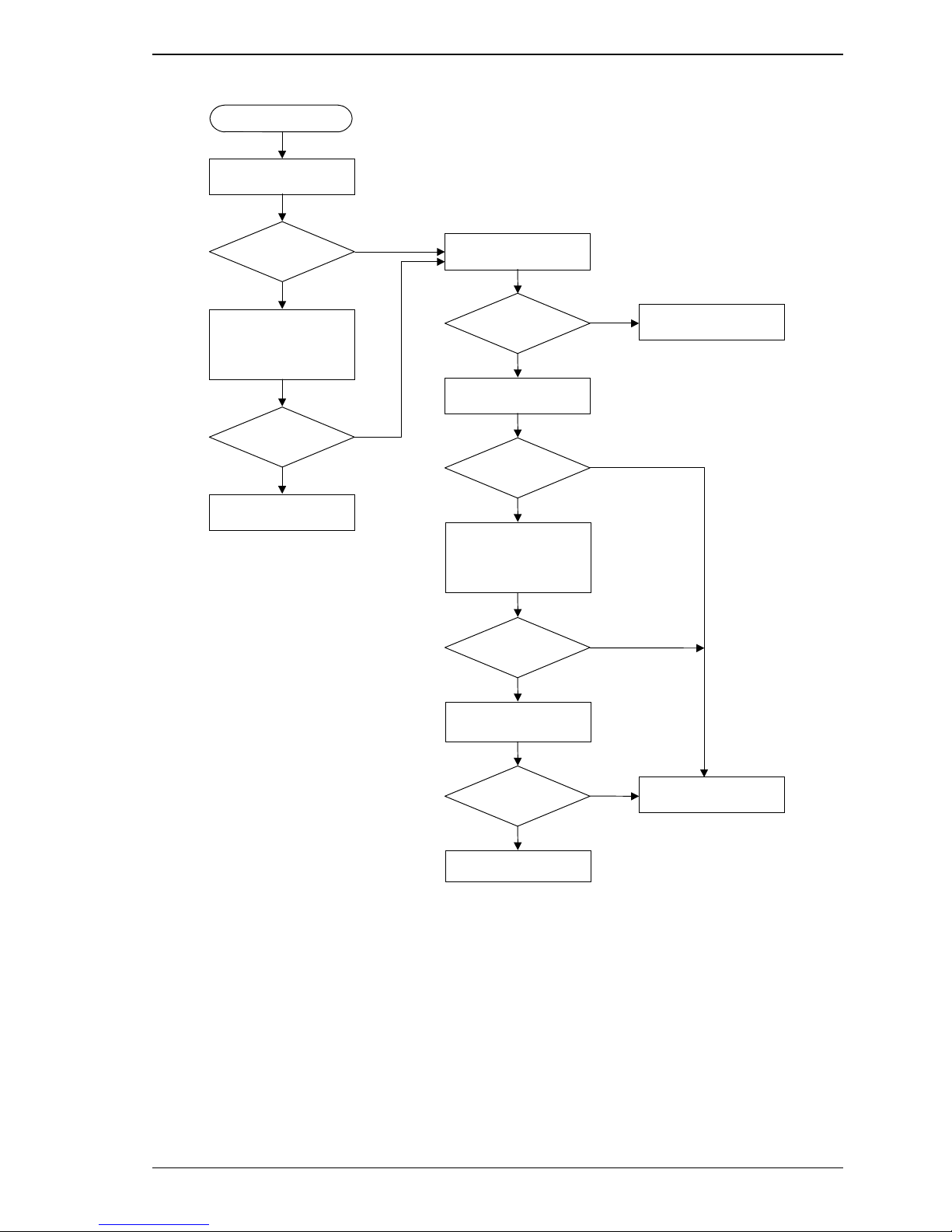
Start
Start self-test by
turning the power on
6.2 Maintenance Information
Test results OK?
Yes
Execute an operation
test using a host
computer or test
equipment
Test results OK?
Yes
Continue operation
No
No
Check host system
(Table 6.2)
Host system
normal?
Yes
Replaced or repair
disk drive
Disk drive
normal?
Yes
Execute diagnostic
test using a host
computer or test
equipment
Test results OK?
Yes
Test using voltage or
temperature stress
No
No
No
Analyze system-related
error
C141-E133-02EN 6-11
Test results OK?
Yes
Normal
Figure 6.3 Test flowchart
No
Analyze disk drive
error (Table 6.3)
Page 94

Diagnostics and Maintenance
6.3 Operation Check
6.3.1 Initial seek operation check
If an error is detected during initialization by the initial seek operation check routine at power-on, the
IDD sends the Fault LED Out signal to the interface connector. The spindle motor of the disk drive
then stops, and the disk drive is unusable .
For an explanation of the operation check before the initial seek, refer to the Section 5.5.
6.3.2 Operation test
While the host computer is processing data, the IDD monitors disk drive operation including data
processing, command processing, and seek operations. If the IDD detects an error, the IDD posts the
error to the INIT. The INIT then posts the error to the user.
The user may detect an intermittent or nonfatal error such as abnormal noise, abnormal odor, or very
slow operation.
An error posted in an operation test must be investigated. Replace the disk drive to see whether the
error was caused by the disk drive.
Often, errors poste d in an operation test may be caused by the host system. Possible causes include
insufficient power capacity, loose cable connection, insufficient timing or insufficient mechanical
play, and problems related to other systems.
If an operation error is detected by the error detection circuit of the disk drive, an interrupt occurs.
The interrupt is posted to the MCU on the PCA. The MCU stops the currently processed command,
and causes the CHECK CONDITION status to post the error to the INIT.
When receiving the CHECK CONDITION status, the INIT issues a REQUEST SENSE command to
collect detailed information about the error. The INIT then issues a REZERO UNIT command to
return the read/write head to track 00. In normal processing, the IDD itself or INIT determines how
to handle the error (processing retry or stop).
To analyze the error posted in the operation test, reconstruct the conditions in which the error
occurred. Then, start troubleshooting the whole host system by replacing the disk drive.
6.3.3 Diagnostic test
The diagnostic test is executed to find a faulty subassembly in a faulty disk drive, or to check disk
drive performance. This test is usually a combination of specific disk drive functions or group of
functions. This test may be executed using a different host computers or test equipment and away
from the environment where the error first occurred.
To analyze the error posted in the diagnostic test, reconstruct the conditions in which the error
occurred. Then, look for a possibly faulty subassembly or part of the disk drive.
The procedures to be used in this test depend largely on the type of test equipment used, and are not
covered by this manual.
6-12 C141-E133-02EN
Page 95

6.4 Troubleshooting Procedures
6.4.1 Outline of troubleshooting procedures
This section explains the troubleshooting procedures for disk drive errors.
Depending on the maintenance level, analyze the error to detect a possibly faulty part (disk drive, or
disk drive part).
Full-scale troubleshooting is usually required if the error cause is not known. If the error cause is
clear (e.g., abnormal noise in disk enclosure or burning of a PCA), troubleshooting is straightforward.
6.4.2 Troubleshooting with disk drive replacement in the field
At this level of maintenance, we recommend replacing the disk drive as a unit. If replacing the disk
drive rectifies the fault, return the removed disk drive to the factory, for test and repair. If the newly
installed disk drive does not rectify the fault another part of the system is faulty.
Table 6.2 summarizes system-level field troubleshooting. Troubleshooting must be done in the field,
to find faulty part (disk drive or system).
6.4 Troubleshooting Procedures
C141-E133-02EN 6-13
Page 96

Diagnostics and Maintenance
Table 6.2 System-level field troubleshooting
Item Recommended work
AC and DC power level Check that the DC voltage is within the specified range (±5%).
Check that the +5 VDC value (pin of the interface connector) is 4.75 to
5.25 VDC.
Check that the +12 VDC supply (pin of the interface connector of disk
drive) is 11.4 to 12.6 VDC.
Electrical noise Make sure the maximum ripple peak-to-peak value of +5 VDC is within
250 mV and +12 VDC is within 250 mV.
Drive selection address Check that the disk drive selection address is set correctly.
System cables Check that all system cables are connected correctly.
System diagnostic test When possible, execute the system level diagnostic routine as explained
in the host computer manual. This gives a detailed report of a possible
fault.
Intermittent or nonfatal errors Check the AC voltage from the power supply. Check the DC voltage
level at the power connector for the disk drive.
If the AC voltage level is abnormal or there is a lot of electrical noise,
notify the user of the error.
If the DC voltage level is unstable, replace the power supply unit.
If possible, replace the disk drive. If replacing the disk drive does not
eliminate the error, the removed disk drive is probably not faulty. To
continue error analysis, refer to the hardware and software manuals
supplied with the system.
6-14 C141-E133-02EN
Page 97

6.4.3 Troubleshooting at the repair site
For maintenance at this level, we recommend additional testing of the disk drive and signal checking.
The sense data posted from the IDD helps with troubleshooting. This sense data mak es the error ty pe clear
(functional, mech anical, or electrical error). Ch apter 7 error analy sis by sens e data, and g ives
supplementary in form ation on fi nding the error caus e (fau lty part).
Table 6.3 lists how to detect a faulty disk drive subassembly. This fault finding requires a working
host computer or disk drive test equipment to recreate the error conditions.
If the detected error cannot be recreated in an ordinary test, disk drive conditions can be changed to
force the error to recur. This is done by changing the DC voltage or the ambient temperature of the
disk drive.
If the error does not recur with changed conditions, the disk drive is not faulty. If no error occurs in
the disk drive test, notify the user of the test results, and find out from the user the environment
conditions where the disk drive is used.
Table 6.3 Disk drive troublesho oting
6.4 Troubleshooting Procedures
Item Recommended action
Frequent or repeated seek errors Collect sense data, and see Chapter 7.
Replace the disk drive, and check that the test method is correct. If the
error recurs, it is likely that the disk drive is normal but the test method
is incorrect.
Intermittent or nonfatal errors Replace the disk drive, and check that the test method is correct. If the
error recurs, it is likely that the disk drive is normal but the test method
is incorrect.
To check performance, change the disk drive conditions by changing
the voltage or temperature.
If the disk drive error recurs or a possibly faulty part is found by troubleshooting, return the complete
disk drive to the factory for repair. A media defect list must be included with a disk drive returned to
the factory.
If the possibly faulty part is the disk enclosure, return the whole disk drive to the factory for repair.
Also if a clear error (erroneous servo track information or noisy drive) is detected in the disk
enclosure, return the whole disk drive to the factory. A media defect list must be included with a disk
drive returned to the factory.
Damage
Never open the disk enclosure in the field. Opening the disk enclosure
in the field may cause an irreparable fault.
C141-E133-02EN 6-15
CAUTION
Page 98

Diagnostics and Maintenance
6.4.4 Troubleshooting with parts replacement in the factory
This manual does not cover troubleshooting at the factory level.
6.4.5 Finding possibly faulty parts
Finding possibly faulty parts in the field was explained in Subsection 6.4.2. This manual does not
cover finding possibly faulty parts at the factory level.
6-16 C141-E133-02EN
Page 99

CHAPTER 7 Error Analysis
7.1 Error Analysis Information Collection
7.2 Sense Data Analysis
This chapter explains in detail how sense data collected from a disk drive is used for troubleshooting. Sense
data reflects an error in the disk drive, and helps with troubleshooting.
A sense key, sense code, and subsense code, taken from various sense data are repeated. Also in this chapter,
troubleshooting is performed using these three codes. Unless otherwise specified, "sense data" means the
above three codes. When sense data is represented as (x-xx-xx), the leftmost x is a sense key, the middle xx is
a sense code, and the rightmost x is a subsense code.
7.1 Error Analysis Information Collection
7.1.1 Sense data
When IDD posts a CHECK CONDITION status or detects a fatal error in the loop, the current
command or queued command is cleared. In such a case, the IDD generates sense data about the
command-issuing INIT. The INIT can read the sense data by issuing a REQUEST SENSE
command.
Even if a transfer byte length that is shorter than the sense data length of the tested device is
specified, the command terminates normally. In this case, however, the INIT receives part of the
sense data, but the remaining part of the sense data is lost.
For details of the REQUEST SENSE command, refer to the Fibre Channel Interface Specifications.
7.1.2 Sense key, sense code, and subsense code
If an error is detected in a disk drive, the error status is indicated in the sense data collected from the
disk drive. Figure 7.1 shows the positions of a sense key, sense code, and subsense code.
C141-E133-02EN 7-1
Page 100
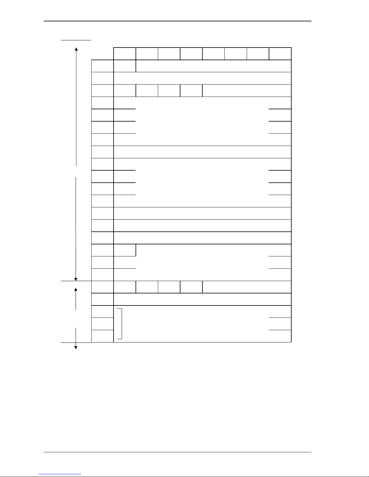
Error Analysis
Bit 76543210
Byte 0 Valid X‘70’ or X‘71’ (error code)
1 X‘00’
20 0 ILI 0 Sense key
3
[MSB]
Basic
information
4
5
6
7 X‘28’ (additional sense data length)
8
[MSB]
9
10
11
12 Sense code
13 Subsense code
14 X‘00’
15 SKSV
16 Sense key-specific information
17
18 X 0 0 0 SCSI ID
Command-specific information
Information
[LSB]
[LSB]
19 CDB operation code
Additional
information
20
Detail information
47
Figure 7.1 Format of extended sense data
7-2 C141-E133-02EN
 Loading...