

Fujitsu MAN3367FC - Enterprise 36.7 GB Hard Drive, MAN3735FC SERIES, MAN3367FC SERIES Product/maintenance Manual

MAN3735FC SERIES
MAN3367FC SERIES
DISK DRIVES
C141-E133-02EN
PRODUCT/MAINTENANCE MANUAL

FOR SAFE OPERATION
Handling of This Manual
This manual contains important information for using this product. Read thoroughly before using
the product. Use this product only after thoroughly reading and understanding especially the section
"Important Alert Items" in this manual. Keep this manual handy, and keep it carefully.
FUJITSU makes every effort to prevent users and bystanders from being injured or from suffering
damage to their property. Use the product according to this manual.
IMPORTANT NOTE TO USERS
READ THE ENTIRE MANUAL CAREFULLY BEFORE USING THIS PRODUCT.
INCORRECT USE OF THE PRODUCT MAY RESULT IN INJURY OR DAMAGE TO
USERS, BYSTANDERS OR PROPERTY.
While FUJITSU has sought to ensure the accuracy of all information in this manual, FUJITSU
assumes no liability to any party for any damage caused by any error or omission contained in this
manual, its updates or supplements, whether such errors or omissions result from negligence,
accident, or any other cause. In addition, FUJITSU assumes no liability with respect to the
application or use of any product or system in accordance with the descriptions or instructions
contained herein; including any liability for incidental or consequential damages arising therefrom.
FUJITSU DISCLAIMS ALL WARRANTIES REGARDING THE INFORMATION
CONTAINED HEREIN, WHETHER EXPRESSED, IMPLIED, OR STATUTORY.
FUJITSU reserves the right to make changes to any products described herein without further notice
and without obligation.
This product is designed and manufactured for use in standard applic at ions such as off ice work,
personal devices and household appliances. This product is not intended for special uses (atomic
controls, aeronautic or space systems, mass transport vehicle operating controls, medical devices for
life support, or weapons firing controls) where particularly high reliability requirements exist,
where the pertinent levels of safety are not guaranteed, or where a failure or operational error could
threaten a life or cause a physical injury (hereafter referred to as "mission-critical" use). Customers
considering the use of these products for miss ion-c rit ica l appl ica tio ns mus t have safe ty-ass u ran ce
measures in place beforehand. Moreover, they are requested to consult our sales representative
before embarking on such specialized use.
Compliance With Taiwanese Standards on Radio Wave Use (BSMI).
C141-E133-02EN

Caution
This computer device shall meet FCC Class A environment. If you use this device at Home
environment, it may affect to the Television set, Radio receiver, and so on.
In this case, you may require to take action to resolve any affection due to this device.
The contents of this manual may be revised without prior notice.
The contents of this manual shall not be disclosed in any way or reproduced in any media without
the express written permission of Fujitsu Limited.
All Rights Reserved, Copyright FUJITSU LIMITED 2002
C141-E133-02EN
Second Edition April, 2002


Revision History
(1/1)
Edition Date
01 2001.12.28 — —
02 2002.04.01 For safe operation Description added
Revised section (*1)
(Added/Deleted/Altered)
Details
*1 Section(s) with asterisk (*) refer to the previous edition when those were deleted.
C141-E133-02EN

This page is intentionally left blank.

This manual describes the MAN3735FC, MAN3367FC (hereafter, MAN series), 3.5 type
fixed disk drives with an embedded fibre channel controller.
This manual details the specifications and functions of the above disk drive, and gives the
requirements and procedures for installing it into a host computer system.
This manual is written for users who have a basic understanding of fixed disk drive s and
their use in computer systems. The MANUAL ORGANIZATION section describes
organization and scope of this manual. The need arises, use the other manuals.
The organization of this manual, related reference manual and conventions for alert
messages follow.
Overview of Manual
This manual consists of the following eight chapters, glossary, and abbreviation:
Chapter 1 General Description
This chapter introduces the MAN series disk drives and discusses their standard features,
hardware, a nd system configuration.
Preface
Chapter 2 Specifications
This chapter gives detailed specifications of the MAN series disk drives and their
installation environment.
Chapter 3 Data Format
This chapter describes the data structure of the disk, the address method, and what to do
about media defects.
Chapter 4 Installation Requirements
This chapter describes the basic physical and electrical requirements for installing MAN
series disk drives.
Chapter 5 Installation
This chapter explains how to install MAN series disk drives. It includes the notice and
procedures for setting device number and operation modes, mounting the disk drive,
connecting the cables, and confirming drive operation.
Chapter 6 Diagnostics and Maintenance
This chapter describes the automatic diagnosis, and maintenance of MAN series disk drive.
This chapter also describes diagnostic methods for operation check and the basics of
troubleshooting the disk drives.
Chapter 7 Error Analysis
This chapter describes in details how collect the information for error analysis and how
analyze collected error information.
C141-E133-02EN i

Preface
Chapter 8 Principle of Operation
This chapter explains disk drives configuration and operation of MAN series.
APPENDIX A to D
The appendixes give supplementary information, including the locations of connector, the
signal assignments of interface connectors, lists of model names and product numbers, and
fibre channel interface functions.
The model numbers have a suffix that describes the electrical requirements of the fibre
channel interface between host system and disk drive, the data formatted at the factory and
device type.
CONVENTIONS USED IN THIS MANUAL
This manual indicates;
Decimal number: Indicates as it is.
Hexadecimal number: Indicates as X’17B9’, 17B9h, or 17B9H
Binary number: Indicates as “010”
DISCLAIMER
Failure of the MAN series intelligent disk drive is defined as a failure requiring
adjustments, repairs, or replacement. Fujitsu is not responsible for drive failures caused by
misuse by the user, poor environmental conditions, power trouble, host problems, cable
failures, or any failure not caused by the drive itself.
The suffix of the model name of the disk drive varies depending on the electrical
requirements, capacity, and data format at factory shipment of the fibre channel, i.e., the
interface for connecting the device type or host system and the disk drives (Note 1).
However, in this manual, the typical model names (Note 2) are used unless otherwise
noted. These disk drives may be called intelligent disk drives (IDD), drives, or devices in
this manual.
Note 1:
M AN 3 735 FC
Model names
Interface types FC: Fibre Channel
Formatted capacity (100 MB units)
Disk drive size 3: 3.5 type. Hard Disk Drive
Type AN: Number of rotations 10,025min
-1
(10,025rpm)
ii C141-E133-02EN

Preface
Note 2:
Conventions for Alert Messages
This manual uses the following conventions to show the alert messages. An alert message
consists of an alert signal and alert statements. The alert signal consists of an alert symbol
and a signal word or just a signal word.
The following are the alert signals and their meanings:
Type model name
Type model name Model name
MAN3735 MAN3735FC
MAN3367 MAN3367FC
This indicates a hazardous situation likely to result in
serious personal injury if the user does not perform the
procedure correctly.
This indicates a hazardous situation could result in serious
personal injury if the user does not perform the procedure
correctly.
This indicates a hazardous situation could result in minor
or moderate personal injury if the user does not perform
the procedure correctly. This alert signal also indicates
that damages to the product or other property, may occur if
the user does not perform the product correctly.
This indicates information that could help the user use the
product more efficiently.
In the text, the alert signal is centered, followed below by the indented message. A wider
line space precedes and follows the alert message to show where the alert message begins
and ends. The following is an example:
C141-E133-02EN iii

Preface
Attention
(Example)
Data loss
For MAN series, Reed Solomon codes are applied for their ECC. The
sector-data is divided into 6 interleaving sectors, and ECC is performed in
each sector where the maximum number of errors (up to 5 byte) can be
corrected. [Total maximum byte: 5 byte × 6 ( interleave) = 30 byte]
If the error of read sector keeps allowable error byte number, correction is
performed. However, if error byte exceeds its allowable number,
correction may not be performed properly.
The main alert messages in the text are also listed in the “Important Alert Items.”
Please forward any comments you may have regar ding this manual.
To make this manual easier for users to understand, opinions from readers are needed.
Please write your opinions or requests on the Comment at the back of this manual and
forward it to the address described in the sheet.
iv C141-E133-02EN

Important Alert Messages
The important alert messages in this manual are as follows:
Important Alert Items
Task Alert message Page
Mounting Installation
A hazardous situation
user does not perform the procedure correctly. Also, damage to the product
or other property,
correctly.
Data loss
For MAN series, Reed Solomon codes are applied for their ECC.
The sector-data is divided into 6 interleaving sectors, and ECC is
performed in each sector where the maximum number of errors (up
to 5 byte) can be corrected. [Total maximum byte: 5 byte
interleave) = 30 byte]
If the error of read sector keeps allowable error byte number,
correction is performed.
However, if error byte exceeds its allowable number, correction
may not be performed properly.
Hot temperature
To prevent injury, do not handle the drive until after the device has
cooled sufficiently after turning off the power. The DE and LSI
become hot during operation and remain hot immediately after
turning off the power.
may
result in
could
occur if the user does not perform the procedure
minor
or
moderate personal injury
×
6 (
if the
2-5
5-1
C141-E133-02EN v
Damage
1. When dismounting the drive which is mounted on the system
while power is supplied to it.
• The drive to be dismounted must be separated from the
loop. Dismounting the drive which is not separated from
the loop may cause an unexpected error.
• If the drive is not separated from the loop, issue an LPB to
the drive from the initiator in a primitive sequence of the
order set.
• It is recommended to stop the spindle moto r prior to this
loop separation operation. The spindle motor can be
stopped by a START/STOP command. It takes about 30
seconds for the spindle motor to stop completely.
5-5

Important Alert Items
Task Alert message Page
Mounting Installation
• Then, dismount the drive using the drive
mounting/dismounting mechanism, etc. of the system. If
the drive is dismounted while the spindle motor is running,
special care is required to avoid excessive vibration or
shock to the drive. It is recommended to stop the operation
once the SCA connector breaks off contact and wait until
the spindle motor stops (about 30 seconds) before dismount
the drive.
• When storing or transporting the drive, put it in an
antistatic bag. (Shown in Section 5.1).
2. When dismounting the drive which is mounted on the system
while power is not supplied to it.
• Do not move the drive until the drive stops completely
(about 30 seconds if the spindle motor was stopped by a
START/STOP UNIT command, and about 30 seconds after
powering-off when the power was simply tu rned off).
• Then, dismount the drive using the drive
mounting/dismounting mechanism, etc. of the system.
• When storing or transporting the drive, put it in an
antistatic bag. (Shown in Section 5.1).
Data loss
When the SEND DIAGNOSTIC command terminates with the
CHECK CONDITION status, the INIT must collect the error
information using the REQUEST SENSE command. The RECEIVE
DIAGNOSTIC RESULTS command cannot read out the error
information detected in the self-diagnostics.
5-5
6-4
Caution
1. To avoid injury, do not touch the mechanical assembly during
disk drive operation.
2. Do not use solvents to clean the disk drive.
Caution
1. Always ground yourself with a wrist strap connected to ground
before handling. ESD (Electrostatics Discharge) may cause
the damage to the device.
2. Do not remove a PCA. This operation is required to prevent
unexpected or unpredictable operation.
3. Do not use a conductive cleaner to clean a disk drive assembly.
Damage
Never open the disk enclosure in the field. Opening the disk
enclosure in the field may cause an irreparable fault.
Data loss
Save data stored on the disk drive before requesting repair. Fujitsu
does not assume responsibility if data is destroyed during servicing
or repair.
6-5
6-6
6-6
6-7
vi C141-E133-02EN

MANUAL ORGANIZATION
PRODUCT/
MAINTENANCE MANUAL
(This manual)
Fibre Channel
Interface
Specifications
1. General Description
2. Specifications
3. Data Format
4. Installation Requirements
5. Installation
6. Diagnostics and Maintenance
7. Error Analysis
8. Principle of Operation
1. Command Processing
2. Data Bu ffer Manage ment
3. Command Specification
4. Sense Data and error Recovery Procedure
5. Disk Medium Management
C141-E133-02EN vii

This page is intentionally left blank.

REFERENCED STANDARDS
The product specifications and functions described in this manual conform to the
following standards:
Specification
(document) number
NCITS TR-19 FIBRE CHANNEL PRIVATE LOOP SCSI DIRECT
ATTATH (FC-PLDA)
ANSI X3.230-1994 FIBRE CHANNEL PHYSICAL AND SIGNALING
INTERFACE (FC-PH)
ANSI X3.297-1996 FIBRE CHANNEL PHYSICAL AND SIGNALING
INTERFACE-2 (FC-PH-2)
ANSI X3.272-199X FIBRE CHANNEL ARBITRATED LOOP (FC-AL)
ANSI X3.269-199X FIBRE CHANNEL PLOTOCOL FOR SCSI (SCSI-
FCP)
Name Concerned o rganization
American National
Standards Institute (ANSI)
C141-E133-02EN ix

This page is intentionally left blank.

CONTENTS
CHAPTER 1 General Description.................................................................. 1-1
1.1 Standard Features....................................................................................1-2
1.2 Hardware Structure .................................................................................1-5
1.3 System Configuration..............................................................................1-7
CHAPTER 2 Specifications............................................................................ 2-1
2.1 Hardware Specifications .........................................................................2-1
2.1.1 Model name and part number ...............................................................2-1
2.1.2 Function specifications .........................................................................2-2
2.1.3 Environmental specifications................................................................2-4
2.1.4 Error rate ............................................................................................... 2-5
2.1.5 Reliability..............................................................................................2-5
CHAPTER 3 Data Format............................................................................... 3-1
3.1 Data Space...............................................................................................3-1
3.1.1 Cylinder configuration..........................................................................3-1
3.1.2 Alternate spare area...............................................................................3-4
3.1.3 Track format..........................................................................................3-5
3.1.4 Sector format.........................................................................................3-7
3.1.5 Format capacity.....................................................................................3-9
3.2 Logical Data Block Addressing ............................................................ 3-10
3.3 Defect Management ..............................................................................3-11
3.3.1 Defect list............................................................................................3-11
3.3.2 Alternate block allocation...................................................................3-11
CHAPTER 4 Installation Requirements........................................................ 4-1
4.1 Mounting Requirements..........................................................................4-1
C141-E133-02EN xi

Contents
4.1.1 External dimensions..............................................................................4-1
4.1.2 Mounting ...............................................................................................4-3
4.1.3 Notes on mounting ................................................................................4-3
4.2 Power Supply Requirements ...................................................................4-7
4.3 Connection Requirements........................................................................4-9
4.3.1 Connector ..............................................................................................4-9
4.3.2 Interface connector................................................................................4-9
CHAPTER 5 Installation..................................................................................5-1
5.1 Notes on Handling Drives .......................................................................5-1
5.2 Setting......................................................................................................5-3
5.2.1 Loop ID setting......................................................................................5-3
5.2.2 Mode settings ........................................................................................5-3
5.3 Mounting Drives......................................................................................5-4
5.3.1 Mounting procedures.............................................................................5-4
5.4 Dismounting Drives.................................................................................5-5
5.5 Checking Operation after Installation and Preparing
the IDD for Use .......................................................................................5-6
5.5.1 Checking initial operation.....................................................................5-6
5.5.2 Checking connection.............................................................................5-7
5.5.3 Formatting ...........................................................................................5-10
5.5.4 Setting parameters...............................................................................5-12
5.6 Spare Disk Drive ...................................................................................5-16
CHAPTER 6 Diagnostics and Maintenance ..................................................6-1
6.1 Diagnostics ..............................................................................................6-1
6.1.1 Self-diagnostics.....................................................................................6-1
6.1.2 Test programs........................................................................................6-4
6.2 Maintenance Information ........................................................................6-5
6.2.1 Precautions ............................................................................................6-5
6.2.2 Maintenance requirements ....................................................................6-6
xii C141-E133-02EN

Contents
6.2.3 Maintenance levels................................................................................6-8
6.2.4 Revision numbers..................................................................................6-9
6.2.5 Tools and test equipment ....................................................................6-10
6.2.6 Tests ....................................................................................................6-10
6.3 Operation Check....................................................................................6-12
6.3.1 Initial seek operation check.................................................................6-12
6.3.2 Operation test......................................................................................6-12
6.3.3 Diagnostic test.....................................................................................6-12
6.4 Troubleshooting Procedures..................................................................6-13
6.4.1 Outline of troubleshooting procedures................................................6-13
6.4.2 Troubleshooting with disk drive replacement in the field..................6-13
6.4.3 Troubleshooting at the repair site .......................................................6-15
6.4.4 Troubleshooting with parts replacement in the factory ......................6-16
6.4.5 Finding possibly faulty parts............................................................... 6-16
CHAPTER 7 Error Analysis............................................................................7-1
7.1 Error Analysis Information Collection....................................................7-1
7.1.1 Sense data..............................................................................................7-1
7.1.2 Sense key, sense code, and subsense code............................................7-1
7.2 Sense Data Analysis................................................................................ 7-3
7.2.1 Error information indicated with sense data.........................................7-3
7.2.2 Sense data (3-0C-03), (4-40-xx), (4-44-xx), and (4-C4-xx)..................7-4
7.2.3 Sense data (1-1x-xx), (3-1x-xx) and (E-1D-00): Disk read error.........7-4
7.2.4 Sense data (5-2x-xx), (5-3D-00), (5-90-00), (B-47-xx), (B-49-00),
(B-4D-xx) and (B-4E-00): fibre channel interface error.......................7-4
CHAPTER 8 Principle of Operation...............................................................8-1
8.1 Outline.....................................................................................................8-1
8.2 Disk Drive Configuration........................................................................ 8-1
8.2.1 Disks......................................................................................................8-2
8.2.2 Heads.....................................................................................................8-2
8.2.3 Spindle mechanism ............................................................................... 8-2
8.2.4 Actuator.................................................................................................8-2
8.2.5 Air filters...............................................................................................8-2
C141-E133-02EN xiii

Contents
8.3 Circuit Configuration...............................................................................8-3
8.4 Power-On Sequence.................................................................................8-5
8.5 Factory-Calibration..................................................................................8-6
8.6 Read/Write Circuit...................................................................................8-7
8.6.1 Head IC..................................................................................................8-7
8.6.2 Write circuit...........................................................................................8-7
8.6.3 Read circuit............................................................................................8-9
8.7 Servo Control...........................................................................................8-9
8.7.1 Servo control circuit..............................................................................8-9
8.7.2 Servo format........................................................................................8-10
8.7.3 Servo frame format..............................................................................8-12
8.7.4 Spindle motor control..........................................................................8-12
8.7.5 Voice coil motor control .....................................................................8-13
APPENDIX A Locations of Connector ...........................................................A-1
A.1 Locations of Connector ..........................................................................A-2
APPENDIX B Connector Signal Allocation....................................................B-1
B.1 Interface (FC-SCA) Connector Signal Allocation..................................B-2
APPENDIX C Model Names and Product Numbers......................................C-1
C.1 Model Names and Product Numbers......................................................C-2
APPENDIX D Fibre Channel Interface Functions..........................................D-1
D.1 Fibre Channel Interface Function Specifications...................................D-2
xiv C141-E133-02EN

Contents
Glossary .........................................................................................................GL-1
Abbreviations .................................................................................................AB-1
Index ..................................................................................................................IN-1
C141-E133-02EN xv

Contents
Figures
Illustrations
Figure 1.1 FC model outer view.....................................................................1-5
Figure 1.2 Disk/head configuration................................................................1-6
Figure 1.3 Example of FC-AL system configuration.....................................1-7
Figure 3.1 Cylinder configuration ..................................................................3-2
Figure 3.2 Spare area in cell...........................................................................3-5
Figure 3.3 Alternate cylinder..........................................................................3-5
Figure 3.4 Track format..................................................................................3-6
Figure 3.5 Track skew/cylinder skew.............................................................3-7
Figure 3.6 Sector format.................................................................................3-8
Figure 3.7 Alternate block allocation by FORMAT UNIT command .........3-13
Figure 3.8 Alternate block allocation by REASSIGN
BLOCKS command ....................................................................3-14
Figure 4.1 External dimensions......................................................................4-2
Figure 4.2 IDD orientations............................................................................4-3
Figure 4.3 Mounting frame structure..............................................................4-4
Figure 4.4 Limitation of side-mounting..........................................................4-4
Figure 4.5 Surface temperature measurement points.....................................4-5
Figure 4.6 Service clearance area...................................................................4-6
Figure 4.7 Current waveform (+12 VDC)......................................................4-7
Figure 4.8 AC noise filter (recommended).....................................................4-8
Figure 4.9 Connector location........................................................................4-9
Figure 4.10 SCA2 type connector ..................................................................4-10
Figure 5.1 Checking the IDD connection (A) ................................................5-8
Figure 5.2 Checking the IDD connection (B).................................................5-9
Figure 6.1 Revision label (example)...............................................................6-9
Figure 6.2 Indicating revision numbers........................................................6-10
Figure 6.3 Test flowchart .............................................................................6-11
Figure 7.1 Format of extended sense data......................................................7-2
Figure 8.1 Circuit configuration.....................................................................8-4
Figure 8.2 IDD operation sequence at power-on............................................8-5
Figure 8.3 Block diagram of read-write circuit..............................................8-8
Figure 8.4 Block diagram of servo control circuit........................................8-10
Figure 8.5 Position of servo track.................................................................8-12
Figure 8.6 Servo frame .................................................................................8-12
Figure A.1 Locations of connector.................................................................A-2
xvi C141-E133-02EN

Tables
Contents
Table 2.1 Function specifications .................................................................2-2
Table 2.2 Environmental/power requirements..............................................2-4
Table 3.1 Zone layout and track capacity .....................................................3-3
Table 3.2 Format capacity...........................................................................3-10
Table 4.1 Surface temperature check point...................................................4-5
Table 5.1 Motor start mode...........................................................................5-3
Table 6.1 Self-diagnostic functions ..............................................................6-1
Table 6.2 System-level field troubleshooting.............................................6-14
Table 6.3 Disk drive troubleshooting..........................................................6-15
Table 7.1 Definition of sense data ................................................................7-3
Table B.1 FC-SCA connector: CN1 ............................................................ B-2
Table C.1 MAN series model names and product numbers.........................C-2
Table D.1 Fibre channel interface function specifications...........................D-2
C141-E133-02EN xvii

This page is intentionally left blank.

CHAPTER 1 General Description
1.1 Standard Features
1.2 Hardware Structure
1.3 System Configuration
This chapter describes the feature and configuration of the intelligent disk drives (IDD).
IDDs are high performance large capacity 3.5 type fixed disk drives with an embedded Fibre-Channel
controller.
The interface used to connect the MAN-series disk drives to the host system complies with NCITS T R-19
Fibre Channel Private Loop SCSI Direct Attach (FC-PLDA), which is the Fibre Channel PLDA standard
covering items ranging from Fibre Channel physical layers to SCSI command protocols.
The high-speed data transfer and long-distance transmission capabilities of Fibre Channel technology and the
powerful command set of the MAN disk driver facilitate creation of high-performance and highly reliable disk
subsystems with large storage capacities.
The data format can be changed to a format different than the default one by re-initializing the data format on
a user system. For more information, refer to the Fibre Channel Interface Specification.
C141-E133-02EN 1-1

General Description
1.1 Standard Features
(1) Compactness
In a compact enclosure having the 3.5-inch HDD form factor, the IDD contains an FC-AL controller,
which supports the Arbitrated Loop technology (FC-AL), a Fibre Channel technology defined by the
related ANSI standard.
(2) FC-AL standard
The IDD provides not only FC-AL basic functions but also the following features:
Arbitration
•
Disconnection/Reconnection
•
Data bus parity
•
Command set which meets the logical specification of the SCSI CCS (Common Command Set
•
for Direct Access Device) requirements (Rev. 4.B)
The SCSI commands can manipulate data through logical block addressing regardless of the physical
characteristics of the disk drive. This allows software to accommodate future expansion of system
functions.
(3) Dual-port support
The IDD has two pairs of driver and receiver sets for the Fibre Channel to support dual-port
connection.
(4) High-speed data transfer
The maximum data-transfer speed on the Fibre Channel loop is 212.5 MB/s. The large-capacity data
buffer of the IDD enables the effective use of such high-speed data transfers available on the Fibre
Channel loop.
(5) Continuous block processing
The addressing method of data blocks is logical block address. The initiator can access data by
specifying block number in a logically continuous data space without concerning the physical
structure of the track or cylinder boundaries.
The continuous processing up to [64K-1] block s in a com m a nd can be ach ieved, an d IDD can perform
continuous read/write operation when processing data blocks on several tracks or cy linder.
1-2 C141-E133-02EN

(6) Programmable multi-segment data buffer
The data buffer is 8M bytes. Data is transferred between Fibre Channel Loop and disk media
through this data buffer. This feature provi des the suitable usage environment for use rs.
Since the initiator can control the disconnect/reconnect timing on the Fibre Channel Loop by
specifying the condition of stored data to the data buffer or empty condition of the data buffer, the
initiator can perform the effective input/output operations with utilizing high data transfer capability
of the Fibre Channel Loop regardless of actual data transfer rate of the disk drive.
(7) Read-ahead cache feature
After executing the READ command, the IDD reads automatically and stores (prefetches) the
subsequent data blocks into the data buffer (Read-ahead caching).
The high speed sequential data access can be achieve d by transf erring th e data from th e data buf fer w ith out
reaccessing the disk in cas e the su bsequen t com m and reques ts the pref etched data block s.
(8) Command queui ng feature
The IDD can queue maximum 128 commands, and optimizes the issuing order of queued commands
by the reordering function. This feature realizes the high speed processing.
1.1 Standard Features
(9) Reserve and release functions
The IDD can be accessed exclusively in the multi-host or multi-initiator environment by using the
reserve and release functions.
(10) Enclosure service function
The IDD supports the enclosure service interface (ESI), which complies with SFF-8067. The ESI
interface enables use of the SCSI-3 enclosure service command set (SES) so that the functions that
specify and read enclosure service information can be used.
(11) Error recovery
The IDD can try to recover from errors in Fibre Channel Loop or the disk drive using its powerful
retry processing. If a recoverable data check occurs, error-free data can be transferred to the initiator
after being corrected in the data buffer. The initiator software is released from the complicated error
recover processing by these error recovery functions of the IDD.
C141-E133-02EN 1-3

General Description
(12) Automatic alternate block reassignment
If a defective data block is detected during read or write the IDD can automatically reassign its
alternate data block.
(13) Programmable data block length
Data can be accessed in fixed-block length units. The data block length is programmable, and can be
specified at initializing with a multiple of four within the range of 512 to 528 bytes.
(14) Defective block slipping
A logical data block can be reallocated in a physical sequence by slipping the defective data block at
formatting. This results in high speed contiguous data block processing without a revolution delay
due to defective data block.
(15) High speed positioning
A rotary voice coil motor achieves fast positioning.
(16) Large capacity
A large capacity can be obtained from 3.5 type disk drives by dividing all cylinders into several
partitions and changing the recording density on each partition (constant density recording). The disk
subsystem with large capacity can be constructed in the good space efficiency.
(17) Start/Stop of spindle motor
Using the SCSI command, the host system can start and stop the spindle motor.
(18) Diagnosis
The IDD has a diagnostic capability which checks internal controller functions and drive operations
to facilitate testing and repair.
(19) Low power consumption
By using highly integrated LSI components, the power consumption of the IDD is very low, and this
enables the unit to be used in wide range of environmental conditions.
(20) Low noise and low vibration
The noise level is low; approx. 3.9/3.6 bels for MAN series. This makes it ideal for office use.
(21) Microcode downloading
The IDD implements the microcode download feature. This feature achieves easy maintainability of
the IDD and function enhancing.
1-4 C141-E133-02EN
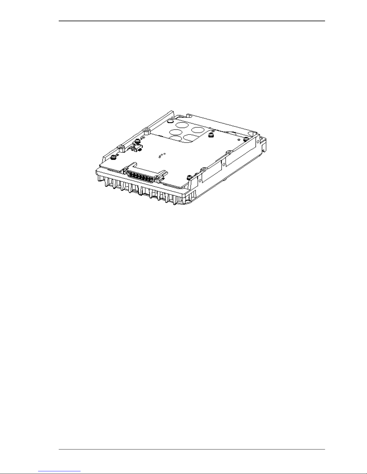
1.2 Hardware Structure
An outer view of the IDD is given in Figures 1.1. The IDD is composed of the disk, head, spindle
motor, mounted disk enclosure (DE) with actuator and air circulation filter, as well as read/write preamp with the print card unit (PCA) of the controller.
1.2 Hardware Structure
(1) Disks
The disks have an outer diameter of 84 mm (3.3 inch) outer diameter and 25 mm (0.98 inch) inner
diameter for MAN series. The disks are good for at least 20,000 contact starts and stops. Each
model contains following number of disks.
Figure 1.1 FC model outer view
MAN3735: 4
MAN3367: 2
C141-E133-02EN 1-5
General Description
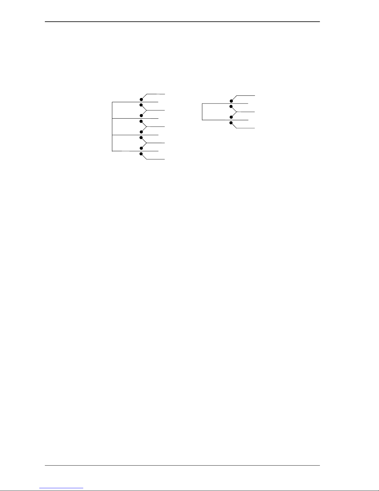
(2) Heads
The MR (Magnet - Resistive) of the CSS (contact start/stop) type heads are in contact with the disks
when the disks are not rotating, and automatically float when the rotation is started. Figure 1.2 shows
the configuration of disks and heads
(3) Spindle motor
The disks are rotated by a direct-drive hall-less DC motor. The motor speed is controlled by a
feedback circuit using the counter electromotive current to precisely maintain the specified speed.
(4) Actuator
MAN3735
0
1
2
3
4
5
6
7
Figure 1.2 Disk/head configuration
MAN3367
0
1
2
3
The actuator, which uses a rotary voice coil motor (VCM), consumes little power and generates little
heat. The heads at the end of the actuator arm is controlled and positioned via feedback of servo
information in the data.
The heads are positioned on the CCS zone over the disk when the power is off or the spindle motor is
stopped.
(5) Air circulation (recirculation filter, breather filter)
The disk enclosure (DE) configures a sealed room to keep out dust and other pollutants. The DE has
a closed-loop air recirculation system. Using the movement of the rotating disks, air is continuously
cycled through a filter. This filter will trap any dust generated inside the enclosure and keep the air
inside the DE contaminant free. To prevent negative pressure in the vicinity of the spindle when the
disks begin rotating, a breather filter is attached. The breather filter also equalizes the internal air
pressure with the atmospheric pressure due to surrounding temperature changes.
1-6 C141-E133-02EN
 Loading...