

Page 1

C141-E124-01EN
MAN3184, MAN3367, MAN3735 SERIES
DISK DRIVES
SCSI LOGICAL INTERFACE SPECIFICATIONS
Page 2

This Product is designed, developed and manufactured as contemplated for general use, including
without limitation, general office use, personal use and household use, but is not designed,
developed and manufactured as contemplated for use accompanying fatal risks or dangers that,
unless extremely high safety is secured, could lead directly to death, personal injury, severe
physical damage or other loss (hereinafter “High Safety Required Use”), including without
limitation, nuclear power core control, airplane control, air traffic control, mass transport operation
control, life support, weapon launching control. You shall not use this Product without securing the
sufficient safety required for the High Safety Required Use. If you wish to use this Product for
High Safety Required Use, please consult with our sale person in charge before such use
The contents of this manual is subject to change without prior notice.
All Rights Reserved. Co pyright ¤ 2001 FUJITSU LIMITED
Page 3

FOR SAFE OPERATION
Handling of This manual
This manual conta ins important information fo r using this p roduc t. Rea d thor oughly befo re using
the product. Use this product only after thoroughly reading and understanding especially the
section “Important Alert Items” in this manual. Keep this manual handy, and keep it carefully.
FUJITSU makes every effort to prevent users and bystanders from being injured or from suffering
damage to their property. Use the product according to this manual.
(Proceed to the Copyright Page)
C141-E124-01EN i
Page 4

Related Standards
Specifications and functions of products covered by this manual comply with the following
standards.
Standard (Text) No. Name Enacting Organization
ANSI X3. 131-1986 American National Standard for Information
ANSI X3. 131-1994 American National Standard for Information
X3T9.2/85-52 Rev 4.B COMMON COMMAND SET (CCS) of the
X3T9.2 855D Rev 12 WORKING DRAFT Information
T10/1236-D Rev 12 WORKING DRAFT Information
ANSI NCITS 306199x
X3T10/994D Rev 18 WORKING DRAFT Information
T10/1302D Rev 11 WORKING DRAFT Information
Systems --- Small Computer System
Interface (SCSI)
Systems --- Small Computer System
Interface-2 (SCSI-2)
Small Computer System Interface (SCSI)
Technology SCSI-3 Parallel Interface
technology SCSI Pri mary Commands-2
(SPC-2)
American National Standard for Information
Technolo gy --- SCSI-3 Block Commands
(SBC)
technology SCSI-3 Architecture Model
(SAM)
technology SCSI Parallel Interface-3 (SPI-
3)
American National
Standards Institute
(ANSI)
American National
Standards Institute
(ANSI)
American National
Standards Institute
(ANSI)
American National
Standards Institute
(ANSI)
American National
Standards Institute
(ANSI)
American National
Standards Institute
(ANSI)
American National
Standards Institute
(ANSI)
American National
Standards Institute
(ANSI)
All Rights Reserved, Co pyright ¤ 2001 Fujitsu, Limited
C141-E124-01ENii
Page 5

REVISION RECORD
Edition Date
published
01 March, 2001
Revised contents
Specification No.: C141-E124-**EN
C141-E124-01EN iii
Page 6

This manual explains concerning the MAH3182/MAH3091, MAK3728 and MAJ3364/MAJ3182/
MAJ3091 series 3.5 inch hard disk drives with internal SCSI controller.
The purpose of this manual is to provide specifications of each command and detailed explanations
of their functions for use of these magnetic disk drives incorporated into user systems, and to
present the information necessary for creating host system software. This manual is written for
users who have a basic knowledge of hard disk drives and their use in computer systems.
The composition of manuals related to these disk drives and the range of subjects covered in this
manual are shown in “Manual Organization,” provided on a subsequent page. Please use these
other manuals along with this manual as necessary.
Remark:
Product development of MAK3728 described in this manual has been discontinued.
Composition and Contents of This Manual
This manual is composed of the 6 chapters shown below, a glossary and a list of abbreviations.
Chapter 1 Command Processing
PREFACE
This chapter describes the basic logical specifications related to SCSI command processing in the
disk drives.
Chapter 2 Data Buffer Management
This chapter describes the data buffer configuration provided in the disk drives and concerning
data transfer processing functions and cache operation.
Chapter 3 Command Specifications
This chapter describes specifications of SCSI commands provided by the disk drives and how to
use them.
Chapter 4 Parameter Data Formats
This chapter describes the parameter data formats provided by the disk drives and how to use
them.
Chapter 5 Sense Data and Error Recovery Methods
This chapter describes the configuration and contents of sense data which report to the host system
when an error occurs, etc., key information necessary for error recovery, recommended procedures
for error recovery to be executed through host system software and retry processing executed
internally in the disk drives for recovery
C141-E124-01ENiv
Page 7

Chapter 6 Disk Media Management
This chapter describes the procedure for initializing the disk media, methods of treating media
defects and data recovery methods for the disk drives.
Glossary
The glossary explains technical terms which are necessary to the reader’s understanding when
reading this manual.
List of Abbreviations
This list shows the full spelling of abbreviations used in this manual.
The model name of disk drives covered by this manual differs in its ending suffix (Note 1)
depending on its device type (3 types), the electrical conditions of the SCSI interface used to
connect the disk drive to the host system and its capacity and data format at the time it was
shipped, but in this manual, excep t in cases where models need to be especially distinguished, a
representative model name (Note 2) is used. In addition, these disk drives are called Intelligent
Disk Drive (IDD), “drive” or “device” in this manual.
Note 1: Model Name
M AH 3
182 MC
Interface type MP: Low voltage differential 16-bit SCSI Ultra-160/m
MC: Low voltage differential 16-bit SCSI Ultra-160/m
SCA2 connector
Formatted capacity (100 MB units)
Disk size
Type AH: 1-inch height (7,200 rpm)
AK: Full-height (10,025 rpm)
AJ: 1-inch height (10,025 rpm)
C141-E124-01EN v
Page 8

Note 2: Typical model name
Type model name Model name
MAH3182 MAH3182MP, MAH3182MC
MAH3091 MAH3091MP, MAH3091MC
MAK3728 MAK3728MP, MAK3728MC
MAJ3364 MAJ3364MP, MAJ3364MC
MAJ3182 MAJ3182MP, MAJ3182MC
MAJ3091 MAJ3091MP, MAJ3091MC
Warning Indications
The following warning indications are shown in this manual to prevent the user and other nearby
persons or property from being injured or damaged.
Note “Note” indicates the most effective method of use or information that is of value to the user.
Requesting for User’s Comments
Please use the User’s Comment Form attached to the end of this manual to identify user comments
including error, inaccurate and misleading information of this manual. Contact to your Fujitsu
representative for additional comment forms if required.
C141-E124-01ENvi
Page 9

Manual Organization
Product/
Maintenance Manual
SCSI Physical
Interface Specifications
SCSI Logical Interface
Specifications
(This Manual)
1. General Description
2. Specifications
3. Data Format
4. Installation Requirements
5. Installation
6. Diagnostics and Maintenance
7. Error Analysis
8. Principle of Operation
1. SCSI Bus
2. SCSI Messages
3. Error Recovery
1. Command Processing
2. Data Buffe r Management
3. Command Specifications
4. Parameter Data Formats
5. Sense Data Error Recovery Methods
6. Disk Media Management
C141-E124-01EN vii
Page 10

CONTENTS
page
CHAPTER 1 COMMAND PROCESSING ..................................................................................1-1
1.1 Command Format .........................................................................................................1-1
1.2 Status Byte....................................................................................................................1-7
1.3 Outline of Command Processing...................................................................................1-10
1.3.1 Single commands..........................................................................................................1-10
1.3.2 Command link...............................................................................................................1-11
1.3.3 Disconnect/reconnect processing..................................................................................1-13
1.3.4 Synchronous mode data transfer/wide mode data transfer............................................1-17
1.4 Command Queuing Function........................................................................................1-19
1.4.1 Untagged queuing.........................................................................................................1-19
1.4.2 Tagged queuing.............................................................................................................1-21
1.5 UNIT ATTENTION Condition ....................................................................................1-23
1.5.1 Generation of the UNIT ATTENTION condition ........................................................1-23
1.5.2 Response and Release Condition at UNIT ATTENTION Condition Hold State..........1-24
1.5.3 UNIT ATTENTION condition multiple hold...............................................................1-25
1.6 Sense Data Hold State...................................................................................................1-26
1.6.1 Sense data hold condition.............................................................................................1-26
1.6.2 Response and release conditions at sense data hold state .............................................1-27
1.7 Command Processing Exceptions.................................................................................1-28
1.7.1 Overlapping commands ................................................................................................1-28
1.7.2 Illegal LUN specification..............................................................................................1-29
1.7.3 Reserved operation code...............................................................................................1-29
1.7.4 Command processing in the not ready state..................................................................1-29
1.7.5 Error recovery processing.............................................................................................1-31
1.7.6 Reset processing...........................................................................................................1-33
1.7.7 Fatal hardware errors....................................................................................................1-35
1.8 Data Block Addressing.................................................................................................1-36
1.8.1 Definition of data space................................................................................................1-36
1.8.2 Logical block addressing..............................................................................................1-38
CHAPTER 2 DATA BUFFER MANAGEMENT ........................................................................2-1
2.1 Data Buffer...................................................................................................................2-1
2.1.1 Data buffer configuration and basic operation..............................................................2-1
C141-E124-01EN ix
Page 11

2.1.2 Operation mode setting.................................................................................................2-5
2.2 Look-Ahead Cache Feature ..........................................................................................2-7
2.2.1 Caching operation.........................................................................................................2-7
2.2.2 Caching parameters.......................................................................................................2-9
2.2.3 Look-Ahead operation, Look-Ahead volume................................................................2-10
2.3 Write Cache..................................................................................................................2-11
CHAPTER 3 COMMAND SPECIFICATIONS...........................................................................3-1
3.1 Control/Sense Commands.............................................................................................3-1
3.1.1 TEST UNIT READY (00) ............................................................................................3-1
3.1.2 INQUIRY (12)..............................................................................................................3-2
3.1.3 READ CAPACITY (25)...............................................................................................3-14
3.1.4 CHANGE DEFINITION (40).......................................................................................3-16
3.1.5 M ODE SELECT (15) ...................................................................................................3-21
3.1.6 M ODE SELECT EXT ENDED (55) .............................................................................3-30
3.1.7 MODE SENSE (1A).....................................................................................................3-32
3.1.8 MODE SENSE EXTENDED (5A)...............................................................................3-38
3.1.9 R EZERO UNIT (01).....................................................................................................3-40
3.1.10 START/STOP UNIT (1B)............................................................................................3-41
3.1.11 RESERVE (16).............................................................................................................3-43
3.1.12 RESERVE EXTENDED (56)......................................................................................3-47
3.1.13 RELEASE (17) .............................................................................................................3-48
3.1.14 RELEASE EXT ENDED (57) ......................................................................................3-49
3.1.15 REQUEST SENSE (03)................................................................................................3-50
3.1.16 LOG SELECT (4C) ......................................................................................................3-52
3.1.17 LOG SENSE (4D) ........................................................................................................3-56
3.1.18 PERSISTENT RESERVE IN (5E)...............................................................................3-58
3.1.18.1 PERSISTENT RESERVE IN service actions...............................................................3-58
3.1.18.1.1 READ KEYS................................................................................................................3-59
3.1.18.1.2 READ RESERVATIONS.............................................................................................3-59
3.1.18.2 PERSISTENT RESERVE IN parameter data for READ KEYS..................................3-59
3.1.18.3 PERSISTENT RESERVE IN parameter data for READ RESERVATION.................3-61
3.1.18.3.1 Persistent reservations scope.........................................................................................3-63
3.1.18.3.1.1 Logical unit scope.........................................................................................................3-63
3.1.18.3.1.2 Element scope (not supported)......................................................................................3-63
3.1.18.3.2 Persistent reservations type...........................................................................................3-63
3.1.19 PERSISTENT RESERVE OUT (5F)............................................................................3-65
x C141-E124-01EN
Page 12

3.1.19.1 PERSISTENT RESERVE OUT service actions...........................................................3-66
3.1.19.2 PERSISTENT RESERVE OUT parameter list.............................................................3-67
3.1.20 REPORT LUNS (A0)...................................................................................................3-69
3.1.21 REPORT DEVICE IDENTIFIER (A3)........................................................................3-71
3.1.22 SET DEVICE IDENTIFIER (A4) ................................................................................3-73
3.2 Data Access Commands................................................................................................3-75
3.2.1 READ (08)....................................................................................................................3-75
3.2.2 READ EXTENDED (28)..............................................................................................3-76
3.2.3 WRITE (0A).................................................................................................................3-77
3.2.4 WRITE EXTENDED (2A)...........................................................................................3-78
3.2.5 WRITE AND VERIFY (2E).........................................................................................3-79
3.2.6 VERIFY (2F)................................................................................................................3-80
3.2.7 SEEK (0B)....................................................................................................................3-81
3.2.8 SEEK EXTENDED (2B)..............................................................................................3-82
3.2.9 SET LIMITS (33) (Not Supported)..............................................................................3-83
3.2.10 SYNCHRONIZE CACHE (35)....................................................................................3-86
3.3 Format Commands........................................................................................................3-87
3.3.1 FORMAT UNIT (04) ...................................................................................................3-87
3.3.2 REASSIGN BLOCKS (07)...........................................................................................3-98
3.3.3 READ DEFECT DATA (37)........................................................................................3-102
3.4 Maintenance, Diagnostic Commands............................................................................3-107
3.4.1 SEND DIAGNOSTIC (1D)..........................................................................................3-107
3.4.2 RECEIVE DIAGNOSTIC RESULTS (1C)..................................................................3-114
3.4.3 WRITE BUFFER (3B).................................................................................................3-118
3.4.4 READ BUFFER (3C) ...................................................................................................3-124
3.4.5 READ LONG (3E).......................................................................................................3-129
3.4.6 WRITE LONG (3F)......................................................................................................3-131
3.4.7 WRITE SAME (41)......................................................................................................3-133
CHAPTER 4 PARAMETER DATA FORMATS.........................................................................4-1
4.1 Mode Parameters..........................................................................................................4-1
4.1.1 Read/Write error recovery parameters (page code = 1)................................................4-1
4.1.2 Disconnect/reconnect parameters (page code = 2)........................................................4-11
4.1.3 Format parameter (page code = 3)................................................................................4-15
4.1.4 Drive parameter (page code = 4)..................................................................................4-19
4.1.5 Verify error recovery parameters (page code = 7).......................................................4-21
4.1.6 Caching parameters (page code = 8).............................................................................4-23
C141-E124-01EN xi
Page 13

4.1.7 Control mode parameters (page code = 0A)................................................................4-29
4.1.8 Notch parameter (page code = 0C)...............................................................................4-33
4.1.9 Informational exceptions control page (page code = 1C).............................................4-35
4.1.10 Additional error recovery parameters (page code = 21)...............................................4-39
4.2 Log Parameters.............................................................................................................4-40
4.2.1 Supprot log page (X'00')...............................................................................................4-40
4.2.2 Buffer overrun / underrun page (X'01').........................................................................4-41
4.2.3 Write error count page (X'02')......................................................................................4-43
4.2.3.1 Write errors recovered without delays (Page 02, Code 0000)......................................4-43
4.2.3.2 Write errors recovered with possible delays (Page 02, Code 0001).............................4-44
4.2.3.3 Total posted write errors (Page 02, Code 0002)...........................................................4-44
4.2.3.4 Total posted recoverable write errors (Page 02, Code 0003)........................................4-45
4.2.3.5 Total write bytes processed (Page 02, Code 0005).......................................................4-45
4.2.3.6 Total posted unrecoverable write errors (Page 02, Code 0006)....................................4-46
4.2.4 Read error count page (X'03').......................................................................................4-46
4.2.4.1 Read errors recovered without delays (Page 03, Code 0000).......................................4-47
4.2.4.2 Read errors recovered with possible delays (Page 03, Code 0001)..............................4-47
4.2.4.3 Total posted read errors (Page 03, Code 0002) ............................................................4-48
4.2.4.4 Total posted recoverable read errors (Page 03, Code 0003).........................................4-48
4.2.4.5 Total read bytes processed (Page 03, Code 0005)........................................................4-49
4.2.4.6 Total posted unrecoverable read errors (Page 03, Code 0006).....................................4-49
4.2.5 Verify error count page (X'05').....................................................................................4-50
4.2.5.1 Verify errors recovered without delays (Page 05, Code 0000).....................................4-50
4.2.5.2 Vefiry errors recovered with possible delays (Page 05, Code 0001) ............................4-51
4.2.5.3 Total posted verify errors (Page 05, Code 0002)..........................................................4-51
4.2.5.4 Total posted recoverable verify errors (Page 05, Code 0003) ......................................4-52
4.2.5.5 Total verify bytes processed (Page 05, Code 0005)......................................................4-52
4.2.5.6 Total posted unrecoverable verify errors (Page 05, Code 0006) ..................................4-53
4.2.6 Non-medium error count page (X'06')..........................................................................4-53
4.2.7 Temperature page (X'0D').............................................................................................4-54
4.2.7.1 Temperature (Page 0D, Code 0000).............................................................................4-54
4.2.7.2 Reference temperature (Page 0D, Code 0001)..............................................................4-55
4.2.8 Start-stop cycle counter page (X'0E')............................................................................4-55
4.2.8.1 Date of manufacture (Page 0E, Code 0001)..................................................................4-56
4.2.8.2 Accounting date (Page 0E, Code 0002)........................................................................4-57
4.2.8.3 Specified cycle count over device lifetime (Page 0E, Code 0003) ...............................4-57
4.2.8.4 Start-stop cycle counter (Page 0E, Code 0004) ............................................................4-58
xii C141-E124-01EN
Page 14

4.2.9 Application client page (X'0F') .....................................................................................4-58
4.2.9.1 General usage application client parameter data (Page 0F, Code 0000-003F).............4-59
4.2.10 Self-test result page (X'10')...........................................................................................4-59
4.2.10.1 Self-test result parameter data (Page 10, Code 0001-0014)..........................................4-60
4.2.11 SMART status page (X'2F')..........................................................................................4-61
4.2.12 SMART data page (X'38').............................................................................................4-61
CHAPTER 5 SENSE DATA ERROR RECOVERY METHODS ..............................................5-1
5.1 Sense Data ....................................................................................................................5-1
5.1.1 Sense data format..........................................................................................................5-1
5.1.2 Sense data basic information.........................................................................................5-3
5.1.3 Sense data additional information.................................................................................5-11
5.2 INIT Error Recovery Methods (Recommended) ..........................................................5-12
5.2.1 Termination status analysis and error recovery methods ..............................................5-12
5.2.2 Sense data analysis and error recovery methods...........................................................5-15
5.2.3 Error logging.................................................................................................................5-23
5.3 Disk Drive Error Recovery Processing.........................................................................5-24
5.3.1 Error states and retry processing procedures ................................................................5-24
5.3.2 Auto alternate block allocation processing ...................................................................5-25
5.3.3 Error recovery processing control.................................................................................5-27
CHAPTER 6 DISK MEDIA MANAGEMENT............................................................................6-1
6.1 Defect Management......................................................................................................6-1
6.2 Disk Media Initialization..............................................................................................6-4
6.2.1 Initialization during installation....................................................................................6-4
6.2.2 Re-initialization ............................................................................................................6-5
6.3 Data Block Verification Methods (Recommended)......................................................6-7
6.4 Alternate Block Allocation Processing.........................................................................6-9
GLOSSARY.......................................................................................................................................GL - 1
ABBREVIATIONS...........................................................................................................................AB - 1
C141-E124-01EN xiii
Page 15

FIGURES
Pages
1.1 6-Byte CDB Basic Format.......................................................................................................1-2
1.2 10-Byte CDB Basic Format.....................................................................................................1-2
1.3 12-Byte CDB Basic Format.....................................................................................................1-3
1.4 Status Byte ...............................................................................................................................1-7
1.5 Data space configuration..........................................................................................................1-37
2.1 Data buffer configuration (in the case of 8 cache segments)...................................................2-2
2.2 Example of data buffer operation during read..........................................................................2-3
2.3 Example of data buffer operation during write.........................................................................2-4
2.4 Parameters for controlling reconnection timing .......................................................................2-5
2.5 Cache control parameters.........................................................................................................2-9
3.1 Standard INQUIRY data..........................................................................................................3-4
3.2 Command support data.............................................................................................................3-9
3.3 VPD information: VPD identifier list......................................................................................3-11
3.4 VPD information: device serial No.........................................................................................3-12
3.5 VPD information: operation mode..........................................................................................3-13
3.6 READ CAPACITY data ..........................................................................................................3-15
3.7 MODE SELECT parameter structure.......................................................................................3-23
3.8 MODE SELECT command (Group 0) parameter configuration..............................................3-25
3.9 MODE SELECT EXTENDED command (Group 2) parameter configuration........................3-31
3.10 MODE SENSE command (Group 0) parameter configuration................................................3-35
3.11 MODE SENSE EXTENDED command (Group 2) parameter configuration ..........................3-39
3.12 SET LIMITS command: Specifying the range where access is permitted...............................3-84
3.13 FORMAT UNIT command parameter list configuration.........................................................3-90
3.14 Defect descriptor: Byte distance from index format................................................................3-93
3.15 Defect descriptor: physical sector address format...................................................................3-94
3.16 REASSIGN BLOCK command: defect data list configuration...............................................3-99
3.17 READ DEFECT DATA command: Defect data configuration...............................................3-103
3.18 SEND DIAGNOSTIC command: parameter list configuration ..............................................3-110
3.19 SEND DIAGNOSTIC parameters: page code list...................................................................3-111
3.20 SEND DIAGNOSTIC parameters: logical/physical address conversion................................3-111
3.21 RECEIVE DIAGNOSTIC RESULTS command: Response data configuration.....................3-115
3.22 RECEIVE DIAGNOSTIC RESULTS response data: page code list......................................3-116
3.23 RECEIVE DIAGNOSTIC RESULTS response data: logical/physical address conversion....3-116
3.24 WRITE BUFFER command: buffer data (Mode = 000, 001).................................................3-119
3.25 READ BUFFER command: buffer data (Mode = 0000, 0001)...............................................3-125
3.26 READ BUFFER command: buffer descriptor..........................................................................3-127
3.27 READ BUFFER command: Echo buffer descriptor.................................................................3-128
xiv C141-E124-01EN
Page 16

4.1 MODE SELECT parameters: read/ write error recovery par ameters........................................4-2
4.2 MODE SELECT parameters: disconnect/ reconnect pa rameters ..............................................4-11
4.3 MODE SELECT para meters: format parameters ....................................................................4-15
4.4 MODE SELECT para meters: drive parameters ......................................................................4-19
4.5 MODE SELECT parameters: verify error recovery parameters..............................................4-21
4.6 MODE SELECT para meters: caching parameters...................................................................4-23
4.7 MODE SELECT parameters: control mode parameters...........................................................4-29
4.8 MODE SELECT parameters: informal exception control page ..............................................4-35
4.9 MODE SELECT parameters: additional err or recovery parameters .......................................4-39
5.1 Expanded sense data format.................................................................................................. ...5-2
5.2 Sense key inherent information................................................................................................5-4
5.3 Analysis of the termination status.............................................................................................5-13
TABLES
1.1 Responses to Link Specification Commands............................................................................1-12
1.2 Types of Command and Disconnect Processing ......................................................................1-14
1.3 Sense data in not ready state ....................................................................................................1-30
1.4 Outline of SCSI Bus Error Recovery Processing.....................................................................1-31
1.5 Outline of disk drive error recovery processing.......................................................................1-32
1.6 Reset processing during write..................................................................................................1-34
3.1 MODE SENSE Data Type Specifications................................................................................3-34
3.2 Persistent reservations type codes............................................................................................3-64
3.3 PERSISTENT RESERVE OUT service action codes..............................................................3-66
3.4 PERSISTENT RESERVE OUT service action and valid parameters......................................3-68
3.5 FORMAT UNIT command defect processing .........................................................................3-96
3.6 Error recovery control flags during the self-diagnosis test.......................................................3-108
4.1 Combination of error recovery flags ........................................................................................4-7
5.1 Sense key..................................................................................................................................5-5
5.2 Sense and subsense codes ........................................................................................................5-6
5.3 Sense data error classification..................................................................................................5-16
5.4 Error recovery processing procedures......................................................................................5-19
5.5 Disk drive errors and number of retries....................................................................................5-28
C141-E124-01EN xv
Page 17

CHAPTER 1 COMMAND PROCESSING
1.1 Command Format
1.2 Status Byte
1.3 Outline of Command Processing
1.4 Command Queuing Function
1.5 UNIT ATTENTION Condition
1.6 Sense Data Hold State
1.7 Command Processing Exceptions
1.8 Data Block Addressing
This chapter describes the basic logical specifications of the IDD command processing functions.
Note:
1.1 Command Format
The IDD operates as the target (TARG) on the SCSI bus. In the explanations in this chapter,
the IDD is mentioned as “TARG”, except in cases where a particularly clear distinction is
necessary.
Input/output operation commands from INIT (initiator) to the IDD are accomplished by the CDB
(Command Descriptor Block). The CDB is information transferred from INIT to TARG in the
COMMAND phase. In a number of commands, the parameters which are necessary for command
execution in the DATA OUT phase may be specified in addition to the CDB specification. Details
concerning these are described in the specifications for each individual command in Chapter 3.
The CDB used by the IDD has 3 formats, these formats have length of 6, 10 and 12 bytes.
The basic format of each respective CDB is shown in Figures 1.1, 1.2 and 1.3.
C141-E124-01EN 1 - 1
Page 18

Bit
Byte
0 Operation Code
1 LUN Logical Block Address (MSB)
2 Logical Block Address
3 Logical Block Address (LSB)
4 Transfer Data Length
5 Control Byte
76543210
Figure 1.1 6-Byte CDB Basic Format
Bit
Byte
0 Operation Code
1 LUN 00000
2 Logical Block Address (MSB)
3 Logical Block Address
4 Logical Block Address
5 Logical Block Address (LSB)
600000000
7 Transfer Data Length (MSB)
8 Transfer Data Length (LSB)
9 Control Byte
76543210
Figure 1.2 10-Byte CDB Basic Format
C141-E124-01EN1 - 2
Page 19

Bit
Byte
0 Operation Code
1 LUN 00000
2 Logical Block Address (MSB)
3 Logical Block Address
4 Logical Block Address
5 Logical Block Address (LSB)
6 Transfer Data Length (MSB)
7 Transfer Data Length (LSB)
8 Transfer Data Length (MSB)
9 Transfer Data Length (LSB)
1000000000
11 Control Byte
76543210
Figure 1.3 12-Byte CDB Basic Format
The meanings of each of the fields in the CDB are explained below. Depending on the type of
command, the basic format of the CDB, the definitions of fields and their meanings may differ.
Details are described in the specifications for each individual command in Chapter 3.
(1) Operation code
Bit 76543210
Group Code Command Code
The leading byte of all CDBs shows the format and type of command to be executed.
a. Group code
The group code specifies the number of bytes and format of the CDB. The groups of
commands shown below are used in the IDD.
x Group 0 (“000”):6-byte CDB (Shown in Figure 1.1)
x Group 1 (“001”):10-byte CDB (Shown in Figure 1.2)
x Group 2 (“010”):10-byte CDB (Shown in Figure 1.2)
x Group 3 ("011"):Reserved Operation Code (Shown in Section 1.7.3.)
x Group 4 ("100"):16-byte CDB
x Group 5 ("101"):12-byte CDB (Shown in Figure 1.3)
C141-E124-01EN 1 - 3
Page 20

b. Command code
Command code specifies the type of command in each group.
(2) LUN (Logical Unit Number)
This field specifies the address of the logical unit (device) connected under the TARG in cases
where the IDENTIFY message is not used. If the IDENTIFY message is used, the value of the
CDB’s LUN field is ignored when the LUN is specified.
Note:
It is possible that the definition of this field may be changed in future SCSI standards. It is
recommended that the LUN be specified using the IDENTIFY message, and that a zero be
specified in this CDB field.
(3) Logical block address
This field shows the leading logical data block address of the data block on the disk media to be
processed by the command. In the group 0 CDB, 21-bit block addressing is possible and in the
group 1, group 2 and group 5 CDBs, 32-bit block addressing is possible. Specifications for logical
data block addressing in the IDD are described in Section 1.8.
(4) Transfer data length
In this field, the length of data to be transferred between INIT and TARG when the command is
executed is specified by the number of logical data blocks or the number of bytes. In subsequent
descriptions, the former is called the “transfer block count” and the latter is called the “transfer
byte length” or “parameter list length.”
Furthermore, thi s field may be used with a diffe rent meaning, or it may not have any meaning at
all, depending on the type of command. There are also some commands which allocate 3 or more
bytes as the transfer data length field. Detailed specifications of these commands are described in
the individual command specifications in Chapter 3.
a. Transfer block count
When the “Transfer Data Length” is specified as the “Transfer Block Count,” this field
specifies the number of logical data blocks to be transferred between INIT and the IDD.
In commands where this field is 1 byte in length, if the field’s specified value is 0, it is
regarded as specifying 256 blocks, and it is possible to specify a block count ranging from 1 to
256 blocks. On the other hand, in commands where this field is 2 bytes in length, if the field’s
specified value is 0, no data transfer is executed. It is possible to specify a block count ranging
from 0 to 65,535 blocks.
C141-E124-01EN1 - 4
Page 21

b. Transfer byte length or parameter list length
When this field is specified as the “Transfer Byte Length” or “Parameter List Length,” that
command specifies data length to be transferred between the INIT and the IDD, expressed as
the number of bytes. When 0 is specified in this field, data transfer is not executed, except in
cases where it is expressly stated in the individual command specifications in Chapter 3.
In commands which send parameters necessary for executing a command from the INIT to the
IDD, this field is called the “Parameter List Length,” and it specifies the total number of types
in the parameter list which the INIT is sending.
On the other hand, in commands for receiving information from the IDD (REQUEST SENSE,
INQUIRY, etc.), this field is called the “Transfer Byte Length,” and specifies the maximum
number of bytes which the INIT can receive (the number of bytes of area secured within the
INIT for receiving information). The IDD transfers either the number of effective bytes of the
type of information specified in the command, or the value specified in the “Transfer Byte
Length” field, whichever is the smallest number of bytes, and only that number, to the INIT.
(5) Control byte
Bit 76543210
0000000Link
a. Link
Command link is specified by this bit is “1.” Details of the operation of the command link are
described in Section 1.3.2.
b. Bit 7, 6 (vendor unique)
Except in cases where it is expressly specified in the individual commands, specification of
these bits has no meaning, and the IDD disregards the specified values.
C141-E124-01EN 1 - 5
Page 22

Note:
It is possible that bits 7 and 6 of the control byte will be used in future product
specifications as an inherent control field. It is recommended that zeros be specified in
this field.
(6) Handling an illegal CDB
If there is an error in the contents of a description (specification) in the CDB, or if there is an error
in the specifications in parameters transferred from the INIT by CDB specifying, that command
ends with a CHECK CONDITION status. In the case of a command to change the data on the
disk media, when there is an error in the CDB’s specifications, the disk media is not changed by
that command. But when there is an error in the parameters transferred in the DATA OUT phase,
the contents of the disk media in the range specified by the command may be changed. Also, even
in cases where there is an error in the CDB’s specifications in a command accompanying the
DATA OUT phase, the DATA OUT phase is executed after the COMMAND phase is terminated,
but those data are not used. For example, if there is an error in the CDB specification of a WRITE
command, the IDD executes the transfers several bytes of data (the data length to be transferred is
not specified), but those data are not written to the disk media. Details are described in the
individual command specifications in Chapter 3.
If there is an error in the CDB specification in a command which executes disconnect processing
(shown in Section 1.3.3), the disconnect processing may be executed after the COMMAND phase
is terminated. In this case, reconnect processing is executed afterward and the status (CHECK
CONDITION) is reported.
Note:
If a CDB with an undefined group code (group 3, 4) is specified, the IDD requests transfer of
10 bytes in the COMMAND phase. After that has been received, the status (CHECK
CONDITION) is reported.
C141-E124-01EN1 - 6
Page 23

1.2 Status Byte
Figure 1.4 shows status byte format and the type of status that the IDD supports.
The status byte is one byte of information sent from the TARG to the INIT in the STATUS phase
when one command is completed, and notifies the INIT of the results of the command’s execution.
The status byte is also sent even in cases when the TARG is in a state which it makes it impossible
for it to execute the command when it receives a request for an input/output operation. However, if
the command is cleare d by switching to the BUS FREE p hase fo rcib ly through an ABORT T ASK
SET message, an ABORT TASK message, a CLEAR TASK SET message, a TARGET RESET
message, a RESET condition or a SCSI bus error state, etc., the status byte for that command is not
reported.
After the TARG reports the status byte in the STATUS phase, it will always send a TASK
COMPLETE message or a LINKED TASK COMPLET E (WITH FLAG) message to no tify the
INIT of the validity of the status byte.
Bit 76543210
0 0 Status Byte Code 0
Bit 5 4 3 2 1
0 0 0 0 0 GOOD Status
0 0 0 0 1 CHECK CONDITION Status
0 0 0 1 0 CONDITION MET Status
0 0 1 0 0 BUSY Status
0 1 0 0 0 INTERMEDIATE Status
0 1 0 1 0 INTERMEDIATE CONDITION MET Status
0 1 1 0 0 RESERVATION CONFLICT Status
1 0 0 0 1 COMMAND TERMINATED Status
1 0 1 0 0 QUEUE FULL Status
Figure 1.4 Status Byte
C141-E124-01EN 1 - 7
Page 24

(1) GOOD status
This status indicates that execution of the command ended normally.
(2) CHECK CONDITION status
This status is reported in the following cases a) to c). The IDD generates sense data when it
reports this status and indicates the detailed cause. The INIT issues a REQUEST SENSE
command when it receives this status and should sample sense data.
a) If the sense key of the sense data indicates RECOVERED ERROR [=1], the last command,
which is the last command, indicates that it ended normally with the error recovery processing
executed by the IDD.
b) If the sense key of the sense data indicates UNIT ATTENTION [=6], it indicates that the IDD
was holding the UNIT ATTENTION condition. Details of the UNIT ATTENTION condition
are described in Section 1.5.
c) In cases other than the above, it indicates that command execution is impossible, or that
command execution was terminated abnormally.
(3) CONDITION MET Status
This status is reported when it is possible to secure the cache memory area necessary for reading all the
logical data blocks specified in the PRE-FETCH command (in the case of “Immed = 1”), or when
reading of all the specified logical data block s is com pleted (in th e case of “Im m ed = 0”).
The IDD does not support the PRE-FETCH command. Therefore, this status is not reported.
(4) BUSY status
This status indicates that the IDD is in the busy state and it cannot receive a new command.
Normally, an INIT that receives this status reissues the original command after waiting an
appropriate period of time.
The IDD reports the BUSY status in the following cases (the command stack function is explained
in Section 1.4).
a) If the IDD receives a new command while it is executing or is queuing command (except a
command without executing disconnect processing as shown in Section 1.3.3) but the INIT
which issued that command does not satisfy the disconnect enable conditions.
b) If the IDD receives a command without executing disconnect processing (as shown in Section
1.3.3) while it is executing or is queuing command.
c) If the DISCONNECT message for command queuing has been rejected by the INIT while the
IDD is executing or queuing command.
d) If a command with executing untagged disconnect processing is received while the command
queue is full.
C141-E124-01EN1 - 8
Page 25

(5) INTERMEDIATE status
This status indicates that a command which specifies a link (except the last command in a group of
linked commands with “1” as its Link bit) has been completed normally. If a command which
specifies a link is completed abnormally and the CHECK CONDITION status or RESERVATION
CONFLICT status is reported, the command link is broken an the subsequent linked commands are
not executed.
(6) INTERMEDIATE CONDITION MET Status
This status is reported when it is possible to secure the cache memory area necessary to read all the
logical data blocks specified in a PRE-FETCH command which specifies a link (in the case of
“Immed = 1”), or when reading of all the specified logical data blocks is completed (in the case of
“Immed = 0”).
The IDD does not support the PRE-FETCH command. Therefore, this status is not reported.
(7) RESERVATION CONFLICT status
This status indicates that the IDD is reserved by another INIT, and that use is impossible until the
reserved status is canceled. Normally, an INIT which receives this status reissues the original
command after waiting an appropriate period of time.
(8) COMMAND TERMINATED status
This status is reported when the IDD has completed the executing input/output operation when it
received a TERMINATE I/O PROCESS message from the INIT.
(9) QUEUE FULL status
This status is reported if the IDD cannot register a received tagged command in the command
queue because there is no empty space in the command queue.
C141-E124-01EN 1 - 9
Page 26

1.3 Outline of Command Processing
1.3.1 Single commands
Following shows single command processing examples which are the most basic operations on the
SCSI bus. Furthermore, if disconnect processing is permitted, it may be accompanied by
disconnect/reconnect processing during the command execution, depending on the type of
command, but this operation is omitted in the following explanation. The disconnect function is
described in Section 1.3.3.
1) The INIT sets the initial values for the command in the command pointer, data pointer and
status pointer.
2) The INIT se lects the TARG in the SELECTION phase a fter obtaini ng the SCSI b us usage in
the ARBIT RATION phase. Aft er the SELECTION p hase is ended, the SCSI bus contro l is
entrusted to the TARG.
3) If the ATT ENTIO N conditio n exists when the TARG respond s to the SELECT ION phase, the
TARG executes the MESSAGE OUT phase. Normally, the INIT sends the IDENTIFY
message as the initial message and specifies the device (LUN) that is the object of the
operation.
4) The TARG executes the COMMAND phase and receives the CDB from the INIT. The TARG
judges the length of the CDB by the group code in the first byte of the CDB and requests
transfer of the necessary number of bytes.
5) The TARG investigates the contents of the command and executes the requested operation. In
the case of commands for which data transfer on the SCSI bus is necessary, the DATA IN or
the DATA OUT phase is executed.
6) When execution of the command is completed, the TARG reports the execution results by the
status byte in the STATUS phase to the INIT.
7) The TARG reports the TASK COMPLETE message to the INIT in the MESSAGE IN phase
and enters the BUS FREE phase.
C141-E124-01EN1 - 10
Page 27

1.3.2 Command link
The command link function is a function which causes the TARG to execute continuous processing
of multiple commands. Following shows examples of command link processing.
1) The INIT sets the initial values for the command in the command pointer, data pointer and
status pointer.
2) Obtaining the SCSI bus usage, selection of the TARG and specification of the LUN by the
IDENTIFY message are the same as in the case of single command.
3) The TARG receives commands from the INIT in the COMMAND phase, but “1” is specified
in the Link bit of the control byte of the CDB.
4) The TARG analyzes the command and executes the requested processing.
5) If processing of the command is completed normally, the TARG reports the INTERMEDIATE
status in the STATUS phase to the INIT. At this time, the command link function becomes
effective.
6) The TARG informs the INIT of the LINKED TASK COMPLETE or the LINKED TASK
COMPLETE WITH FLAG message, depending on the value of the Flag bit in the control byte
of the CDB. When the INIT has received the LINKED TASK COMPLETE (WITH FLAG)
message, the command, data and status pointers are updated to the initial values for the next
linked command.
7) The TARG enters the COMMAND phase immediately after the MESSAGE IN phase and
receives the command to be executed next. After that, it performs either single command
(Link bit = “0”) processing o r command link (Link bit = “1”) proc essing.
The command link continues until a command with “0” specified in the Link bit of its CDB is
issued or until a command terminates abnormally.
The command link function is made effective only in the case that commands with link
specifications are completed normally. If a command with a link specification is completed in an
error state or in an exception state, the command link function is invalidated. Table 1.1 shows the
response of the IDD when commands with a Link specification are terminated.
C141-E124-01EN 1 - 11
Page 28

Table 1.1 Responses to Link Specification Commands
Flag End Status Status Message Link Function
0
1
u
0
1
u
u
u
u
Completed
Normally
Completed
Normally
Completed
Abnormally
Conditions Met INTERMEDIATE
Conditions Met INTERMEDIATE
Unable to Start
Receive
Reserved State RESERVATION
Forced
Termination
Queue Full State QUEUE FULL TASK COMPLETE Not Effective
INTERME DIATE LINKED TASK COMPLETE Effective
INTERMEDIATE LINKED TASK COMPLETE WITH
FLAG
CHECK CONDITION TASK COMPLETE Not Effective
LINKED TASK COMPLETE Effective
CONDITION MET
LINKED TASK COMPLETE WITH
CONDITION MET
BUSY TASK COMPLETE Not Effective
CONFLICT
COMMAND
TERMINATED
FLAG
TASK COMPLETE Not Effective
TASK COMPLETE Not Effective
Effective
Effective
Only a single logical unit can operate a series of linked commands. When the IDD receives the
first command, the logical unit specified by the IDENTIFY message or the LUN field of the CDB
becomes the object of operation in a series of linked commands and the values specified in the
LUN field in the second and subsequent CDBs are disregarded.
Note:
An INIT which uses the command link function must make the ATN signal in the
SELECTION phas e TRUE and not ify the TARG that it i s capa ble o f receiving messages other
than the
TASK
COMPLETE message. If “1” has been specified in the Link bit of the CDB
without the ATN being made TRUE by the INIT in the SELECTION phase, the IDD
terminates that command abnormally by sending a CHECK CONDITION status (ILLEGAL
REQUEST [=5] / Invalid field in CDB [=24-00]).
C141-E124-01EN1 - 12
Page 29

1.3.3 Disconnect/reconnect processing
When processing is performed by the TARG during the command execution process which does
not require operation on the SCSI bus, the TARG can return the SCSI bus to the BUS FREE phase
temporarily by disc onnect p roce ssing and exe cute command int ernally. T hrough thi s function, the
INIT is enabled to process multiple commands on the SCSI bus.
(1) Disconnect permission conditions and commands with executing disconnect process
If all of the conditions shown below for permitting a disconnect are satisfied, the IDD executes
disconnect processing. However, As shown in Table 1.2, disconnect processing may be valid or
invalid, and the disconnect processing execution timing may differ, depending on the type of
command.
Conditions for Permitting a Disconnect
1) The SCSI ID of the INIT is notified in the SELECTION phase.
2) The I NIT generates the ATTENTION condition in the SELECTION phase.
3) The INIT notifies the TARG that disconnect processing is permitted by an IDENTIFY
message.
C141-E124-01EN 1 - 13
Page 30

Table 1.2 Types of Command and Disconnect Processing
Commands with executing disconnect processing. (
Commands without executing disconnect processing. (
C CHANGE DEFINITION (40) O
F FORMAT UNIT (04) O
I INQUIRY (12) O
L LOG SELECT (4C) O
LOG SENSE (4D) O
M MODE SELECT (15) O
MODE SELECT EXTENDED (55) O
MODE SENSE (1A) O
MODE SENSE EXTENDED (5A) O
N
P PERSISTENT RESERVE IN (5E) O
PERSISTENT RESERVE OUT (5F) O
R READ (08) O
READ BUFFER (3C) O
READ CAPACITY (25) O
READ DEFECT DATA (37) O
READ EXTENDED (28) O
READ LONG (3E) O
REASSIGN BLOCKS (07) O
RECEIVE DIAGNOSTIC RESULTS (1C) O
RELEASE (17) O
REPORT DEVICE IDENTIFIER (A3) O
REPORT LUN (A0) O
REQUEST SENSE (03) O
RESERVE (16)
REZERO UNIT (01) O
S SEEK (0B) O
SEEK EXTENDED (2B) O
SEND DIAGNOSTIC (1D) O
SET DEVICE IDENTI FIER (A4) O
START/STOP UNIT (1B) O
SYNCHRONIZE CACHE (35) O
T TEST UNIT READY (00) O
VVERIFY (2F) O
WWRITE (0A) O
WRITE AND VERIFY (2E) O
WRITE BUFFER (3B) O
WRITE EXTENDED (2A) O
WRITE LONG (3F) O
WRITE SAME (41) O
Note 1
)
Note 2
)
(
Note 1
(
Note 2
) Commands without executing disconnect processing: In cases only where commands are
issued without a tag, queuing processing (see Section 1.4) and disconnect processing cannot be
performed in the execution sequence.
) Commands with executing disconnect processing: Regardless of command queuing, in a
command’s execution process (after the COMMAND phase is completed, or during or after the
completion of data transfer), dis conn ect processin g is perf orm ed. How ev er, in th e case of comm an ds
with a data state (in cases where it is hit in the cache, etc.), or with a number of processing modes,
C141-E124-01EN1 - 14
Page 31

other than cases where the command is in a queue, disconnect processing may not be executed
depending on the processing conten t specification of th e com m and.
(2) Basic disconnect processing procedure
Disconnect processing is executed basically by the following processing procedure.
1) If the IDD judges that it is possible for it to disconnect from the SCSI bus during execution of
a command, it sends a DISCONNECT message to the INIT and enters the BUS FREE phase.
At this time, if necessary, the IDD sends a message to activate a pointer in the INIT which
precedes sending of the DISCONNECT message. Furthermore, for details concerning
pointers, refer to the SCSI pointer description in “SCSI Physical Interface Specifications” and
“Chapter 2 SCSI Message s.”
2) After the IDD enters the BUS FREE phase, it is possible for the INIT to issue other commands.
Also, it is possible for an IDD which has performed disconnect processing to receive
input/output operation requests from each INIT (this is explained in the description of the
command queuing function in Section 1.4).
3) The IDD executes the command which performs disconnect processing internally.
4) After that, the IDD executes reconnection processing at the point, when it is necessary for
operation on the SCSI bus, to reconnect with the INIT (See item (6) concerning reconnection
processing).
(3) Disconnect processing procedure after COMMAND phase execution
If commands are queued (see Section 1.4), disconnect processing is performed immediately after the
COMMAND phase execution is completed. In this case, the IDD switches from the COMMAND phase
to the MESSAGE IN phase and sends the DISCONNECT message to the INIT.
(4) Disconnect processing procedure after data transfer execution
For commands which accompany a data transfer, disconnect processing may be performed during
DATA IN or DATA OUT phase execution or after transfer of the last data is completed. In this
case, caution is necessary when executing the following types of pointer controls.
a. If disconnecting during a data transfer
In cases where data transfer has begun (i n DATA IN or DAT A OUT phase) and it will take time
until transfer of subsequent data can be transferred (example: When the data buffer has been
emptied by a READ command, or the data buffer has ceased to be empty due to a WRITE
command), disconnect processing is performed during data transfer. In this case, the IDD sends
the SAVE DATA POINTER message before sending the DISCONNECT message. When the
INIT receives the SAVE DATA POINTER message, it must save the current value of the current
data pointer and make it possi ble to trans f er data f rom the subsequent data at reconnection time.
C141-E124-01EN 1 - 15
Page 32

b. If disconnecting after the final data transfer is completed
In the case of a disconnect after transfer of all the data necessary for execution of a command
has been completed normally, (example: a WRITE command), the IDD sends a
DISCONNECT message after sending the SAVE DATA POINTER message.
After that, the IDD executes reconnection processing and enters the STATUS phase
immediately and reports the status byte without requesting a data transfer.
Note:
In disconnect processing in this case, transfer of all the data accompanying execution of
the command is complete and there is actually no necessity for the SAVE DATA
POINTER message.
However, by issuing the SAVE DATA POINTER message, processing time increases due
to the message transfer, but as a result of the pointer restore operation that is executed
internally by the INIT during reconnection processing for the status report, the current
data pointer can reflect the final results of the data transfer.
(5) Disconnect processing exceptions
When the previously mentioned disconnect processing is executed, if the ATTENTION condition is
generated for the DISCONNECT message sent by the IDD and the INIT returns the MESSAGE
REJECT message, the IDD executes the command with the connections to the SCSI bus remaining as is,
without executing disconnect processing. Cases of disconnect processing in which a pointer operation is
necessary and the SA VE DA TA POINTER mes sage is rejected are the sam e.
(6) Reconnection processing procedure
The reconnection processing procedure is as shown below.
1) The IDD executes the ARBITRATION phase at the point when processing on the SCSI bus is
necessary and gets the SCSI bus control right, then reconnects with the INIT in the
RESELECTION p hase.
2) After that, the IDD sends the IDENTIFY message to the INIT and notifies it of the logical unit
number (LUN) necessary for reconnection processing. If a tagged queuing command is
executed, the IDD sends the SIMPLE message to inform the INIT of the tag ID. The INIT
reads the Saved pointer (command, data and status) corresponding to the LUN specified at this
time and restores it to the current pointer.
Note:
1) If there is no response from the INIT within the specified time (default: 250 ms) in
the RESELECTION phase, the IDD performs timeout processing, then enters the
BUS FREE phase. In this case, after waiting 200 ms or longer, the IDD executes the
predetermined number of retries (re-executing the RESELECTION phase).
However, if it still cannot reconnect with the INIT after that, the IDD clears the
C141-E124-01EN1 - 16
Page 33

command necessary for reconnection processing and generates sense data indicating
ABORTED COMMAND[=B]/Select /Reselect failure[=45-00].
2) If the INIT rejects the IDENTIFY message, or if it rejects the SIMPLE message
when executing a tagged queuing command, the IDD clears the command that was
being executed during reconnection processing and enters the BUS FREE phase. In
this case, the IDD generates sense data indicating ABORTED
COMMAND[=B]/Message error[=43-00].
3) After the INIT that accepts the IDENTIFY message normally completes the pointer restore
operation, it should make the ACK signal for the IDENTIFY message FALSE. If the
ATTENTION condition does not exist when the ACK signal becomes FALSE during sending
of the IDENTIFY message, the IDD regards the reconnection processing as having been
normally completed a nd begins subsequent processing.
For further details, refer to CHANGE DEFINITION parameter list (Reselection Retry,
Reselection Time-out Delay) in Section 3.1.4 and SCSI Bus (RESELECTION phase) in
Chapter 1 of “SCSI Physical Interface Specifications” and SCSI Bus Error Recovery
Processing in Chapter 3.
1.3.4 Synchronous mode data transfer/wide mode data transfer
The IDD equips a synchronous mode data transfer function and wide mode data transfer function
for processing high speed data transfers (DATA IN and DATA OUT phases) on the SCSI bus.
Data transfers on the SCSI bus can be executed in any desired combination of the asynchronous
mode or synchronous mode and in 8 bit widths or 16 bit widths (wide mode), but by using
synchronous mode data transfer or wide mode data transfer, command processing time is shortened
and throughput for input/output processing by multiple command proce ssing using idle time on the
SCSI bus can be improved.
After IDD power on, after generating a RESET condition on the SCSI bus or after one of the INITs
issues a TARGET RESET message, the data transfer mode (default mode) of the IDD is the
asynchronous mode. To use wide mode data transfer, the INIT must exchange a WIDE DATA
TRANSFER REQUEST message o r P ARALLEL PROT O COL REQUEST messa ge with the IDD ,
and determine the SCSI bus width. To use the synchronous mode data transfer, the INIT must
exchange the SYNCHRONOUS DATA TRANSFER REQUEST message or PARALLEL
PROTOCOL REQUEST message and determine parameters necessary for executing the
synchronous mode transfer. When exchange of the WIDE DATA TRANSFER REQUEST
message or PARALLEL PROTOCO L REQUEST message is complet ed, if the synchr onous mode
has been established between the INIT and IDD previously, note that the asynchronous mode is
set.
The INIT which uses wide mode data transfer normally sends the WIDE DATA TRANSFER
REQUEST or PARALLEL PROTOCOL REQ UEST message to the IDD following the IDENTIFY
message after the initial SELECTION phase, and requests the T ARG (IDD) to set the SCSI bus
width in the wide mode. Also, if synchronous mode data transfer is used, after establishing the
SCSI bus width, the INIT exchanges the SYNCHRONOUS DATA TRANSFER REQUEST
message or PARALLEL PRO TOCOL REQUEST message and req uests the TARG (ID D) to set
the synchronous data transfer mode.
C141-E124-01EN 1 - 17
Page 34

The data transfer mode set with the INIT once is effective until a RESET condition occurs or until
a TARGET RESET message is issued by any INITs. Therefore, in order for the INIT to avoid
overhead time for message exchange, the INIT should not send the WIDE DATA TRANSFER
REQUEST message and the SYNCHRONOUS DATA TRANSFER REQUEST message or
PARALLEL PROTO COL REQUEST message to the T ARG each time the SELECTION p hase is
executed.
When the requesting synchronous mode transfer/wide mode data transfer by specifying of the
CHANGE DEFINITION command (synchronous mode transfer/wide mode data transfer request)
is permitted, and the IDD is maintaining the default transfer mode (asynchronous, 8-bit width), if a
WIDE DATA TRANSFER REQUEST message is not sent from the INIT, the IDD enters the
MESSAGE IN phase immediately after the COMMAND phase and sends the WIDE DATA
TRANSFER REQUEST message to the INIT for attempting to set the 16-bit width mode. After
establishing the bus width, the IDD sends the SYNCHRONOUS DATA TRANSFER REQUEST
message to the INIT and attempts the synchronous mode transfer parameters (REQ/ACK offset =
127, Transfer period = 25 ns).
The IDD maintains data transfer mode settings between itself and each INIT individually.
Therefore, an INIT which uses asynchronous mode transfer and an INIT which uses synchronous
mode transfer can both coexist on the same SCSI bus. Also, the parameters for synchronous mode
transfers decided by the SYNCHRONOUS DATA TRANSFER REQUEST message can differ for
each INIT and an INIT which uses the 8-bit width transfer mode can coexist with an INIT which
uses the 16-bit width transfer mode.
Note:
When the INIT issues the first command after the TARG’s power is switched on, or after a
RESET condition occurs, it can send the WIDE DATA TRANSFER REQUEST message and
the SYNCHRONOUS DATA TRANSFER REQUEST message. However, when the TARG is
set internally on a data transfer mode established previously by a TARGET RESET message
issued by another INIT, generally, the INIT is not aware of it. In such case, when requesting
synchronous mode/wide mode transfer is permitted by the specification of the CHANGE
DEFINITION command (synchronous mode/wide mode transfer request), the TARG (IDD)
sends the WIDE DATA TRANSFER REQUEST and SYNCHRONOUS DATA TRANSFER
messages to establish the synchronous mode/wide mode transfer again. Thus, the INIT shall
respond to these messages for setting necessary parameters a ga i n.
See “CHANGE DEFINITION” in Section 3.1.4, SCSI Bus (INFORMATION TRANSFER Phase)
in Chapter 1 and SCSI Messages (SYNCHRONOUS DATA TRANSFER REQUEST, WIDE
DATA TRANSFER REQUEST, PARALLEL PROTOCOL REQUEST) in Chapter 2 of “SCSI
Physical Interface Specifications” for further details.
C141-E124-01EN1 - 18
Page 35

1.4 Command Queuing Function
The IDD equips a command queuing function. Through queuing of commands, the IDD can
receive multiple commands in advance and execute them.
There are two methods use d in the q ueuing functi on, tagge d and unt agged. I n tagged queuing, t he
IDD can receive multiple commands from each INIT. In untagged queuing, the IDD can receive a
single command from each INIT.
Both queuing methods are possible for the IDD, but an INIT can use only one queuing method at a
time. However, if another INIT selects a different method, the IDD controls both methods of
command queuing.
1.4.1 Untagged queuing
Using untagged queuing, the IDD can receive a command from an INIT while it is executing
processing of a command from another INIT. The IDD can receive one command at a time from
each INIT. It is the role of the INIT to confirm that only one command is issued every time.
When the IDD receives a new command from an INIT, if it is processing another command from a
different INIT, or if it is currently executing its initial self-diagnosis, that command is queued in
the command queue. In this case, the IDD executes disconnect processing after command queuing
processing is completed.
After the IDD finishes executing the current processing command, if there is a command in the
queue, it fetches that command and executes it. If there are multiple commands in the queue, they
are fetched and executed in the order in which they were received.
When a command is in the queued state, if a RESET condition occurs, or if the IDD receives a
TARGET RESET message from any INIT, it clears all the commands in the queue. At this time,
the IDD generates on UNIT ATTENTION condition for all the INITs.
When an ABORT message is sent from an INIT that has issued a command which is in the queue,
if the correct LUN (0) is specified, only the command issued by that INIT is cleared and the other
commands in the queue are not effected. If the LUN is not identified, an ABORT message which
specifies an illegal LUN (1 to 7) does not effect the commands in the queue.
Untagged queuing exception processing (events and operations executed by the IDD) is shown
below.
• If the TEST UNIT READY, REQUEST SENSE or INQUIRY command is received.
When one of these commands is received, if there is no link instruction in that command, the IDD
executes that command immediately without queuing the command or executing disconnect
processing. At this time, there is no effect on the commands from other INITs which are currently
being executed, or on the commands in the queue.
If these commands contain link instructions, they are queued.
C141-E124-01EN 1 - 19
Page 36

• If disconnect processing is impossible.
If disconnect processing is impossible because the INIT which issued the command does not meet
the conditions for permitting a disconnect (see Section 1.3.3), or if the DISCONNECT message is
rejected by the INIT even though it meets the conditions for permitting a disconnect, the IDD
responds with a BUSY status without queuing the received command except the case described in
item 1) in following Note during executing or queuing command already. If this is not the case,
the received command is executed immediately.
• If the IDD is reserved
If the IDD has been reserved by an INIT using the RESERVE command and receives a TEST
UNIT READY command after that, when that command conflicts with the reserved state, it
responds with a RESERVATION CONFLICT status. Commands after that are queued, and the
reserved state is checked when a command is fetched from the queue. Conflicts with the reserved
state are explained in the description of the RESERVE command (Section 3.1.11).
Note:
Through the o peration of the c ommand queuing function, exc ept for excep tions describ ed on
this page, the IDD does not respond to commands issued by the INIT with a BUSY status.
This function is applied under the multi-initiator environment, and overhead for re-issuing
commands caused by the BUSY status is unnecessary. Normally, the INIT does not have to be
aware of the existence of a queuing function, but it is necessary to exercise caution in the
following items when controlling input/output processing.
1) When a command is queued, the time from the queuing of the command to its actual
execution will vary depending on the commands already in the queue, or on the content of
the processing currently being executed. Particularly in cases where the FORMAT UNIT
command and START/STOP UNIT command (Immed = 0), and data access commands
which specify large processing block counts, are already queued or being executed, the
newly queued command will be forced to wait a long time until it is executed.
2) In the following cases, a command may not be executed even after it has been queued.
a) When there is an error in the CDB, the IDD responds with a CHECK CONDITION
status at the point when that command is fetched from the queue.
b) If the IDD is in the not ready state at the point when the queued command is fetched,
it responds with a CHECK CONDITION status.
c) If a UNIT ATTENTION condition is generated before the queued command is
fetched, a CHECK CONDITION status may be replied.
C141-E124-01EN1 - 20
Page 37

1.4.2 Tagged queuing
Through the tagged queuing function, the IDD can receive multiple commands from the same INIT
or from different INITs until the command queue is full. The number of commands that it is
possible to receive by the IDD is 128 maximum, without relation to the INIT. When the IDD
receives a new command, if the command queue is full, it responds to the new command with the
QUEUE FULL status.
The IDD manages the command queue, but it is possible for the INIT to add or clear commands
from the queue. When adding a command to the queue, it is possible for the INIT to specify the
order in which commands should be executed or the command that should be executed next to the
IDD.
If the disconnect right is not recognized in the IDENTIFY message of a tagged command, the IDD
responds with a BUSY status.
Through the QUEUE TAG message, the INIT can attach a unique tag (ID) to each command. The
INIT can set that command’s pointer correctly by the tag sent when the IDD reconnects. One INIT
can issue multiple commands to the IDD only when the respective commands have unique tags.
If an ORDERED message is used, the IDD executes the other commands not included in the
ORDERED message in the order in which they are received. All commands received with a
SIMPLE message before commands are received with an ORDERED message are executed before
those commands received with the ORDERED message. All commands with SIMPLE messages
received after commands received with the ORDERED message are executed after the commands
received with the ORDERED message.
Commands received with a HEAD OF QUEUE message are registered at the top of the queue for
waiting execution. The IDD does not interrupt the current command execution and executes them
after completion of current command execution. When commands with the HEAD OF QUEUE
message are received continuously, the IDD first executes the command which was received last.
During the IDD executes or queues a tagged command, the same INIT must issue untagged
commands except when the IDD is in the sense hold state.
The IDD handles a series of linked commands as if it were processing a single command and
processes the series of commands by the tag received with the first command. A command with a
HEAD OF QUEUE received before processing of a series of linked commands is completed is
executed by the IDD after all the linked commands in the series have been executed.
The RESERVE, RELEASE and RESERVE EXTENDED commands should be issued together
with an ORDERED message. If the HEAD OF QUEUE message is used with these commands,
previously issued commands and reserved states may become redundant.
The TEST UNIT READY and INQUIRY commands do not influence the state of the IDD, so they
can be issued together with a HEAD OF QUEUE message.
The INIT can specify 2 error recovery options by the QErr bit of the control mode parameter (Page
A) of the mode select parameters.
C141-E124-01EN 1 - 21
Page 38

When “0” is specified in the QErr bit, the IDD enters any one of a number of sense hold states, and
when this state is released, it continues to execute the commands in the queue. The IDD queues
any commands received from other INITs while it is in the sense hold state, but during this period,
execution of all the commands in the queue is interrupted.
If “1” is specified in the QErr bit, if the IDD enters any one of a number of sense hold states, the
queue is cleared after the sense hold state is released. When the queue is cleared through this
recovery option, the UNIT ATTENTION condition is generated for all the INITs which had their
commands cleared (excluding the INIT that set the sense hold state). The sense code Commands
cleared by another INIT [=2F-00] is set.
Deferred errors are reported for all commands that have already been completed. Therefore, the
queue tag values attached to those commands are not reported.
If a QUEUE TAG message is received by the IDD when tagged commands are prohibited by the
DQue bit of the control mode page, the IDD rejects the message with the MESSAGE REJECT
message processes the accompanying command as an untagged command.
The ABORT TASK SET, ABORT TASK, TARGET RESET or CLEAR TASK SET message is
used to clear some or all of the commands in the queue. See “SCSI Physical Interface
Specifications” for details.
If ‘0001’ is specified in the Queue algorithm modifier of the control mode page, the IDD performs
command reordering processing of commands issued with a SIMPLE message. Reordering
processing is performed with the objective of reducing total processing time for command
processing.
• Conditions for Reordering:
If a command which is the object of reordering is issued by an INIT that permits reordering
with an accompanying SIMPLE message.
• Commands which are Objects of Reordering:
READ, READ EXTENDED, WRITE, WRITE EXTENDED
If an INIT permits command reordering processing, the IDD changes the processing order of the
commands. It is necessary for the INIT to manage concerning the legality of the data, etc.
Section 4.1.7, “Control mode parameters (page code = 0A)” for details of the control mode page.
C141-E124-01EN1 - 22
Page 39

1.5 UNIT ATTENTION Condition
The UNIT ATTENTION condition is a function used to notify the INIT asynchronously of an
event (status change) that has occurred in the TARG or logical unit.
1.5.1 Generation of the UNIT ATTENTION condition
Events which cause a UNIT ATTENTION condition to be generated are one of the following.
(1) When power on, RESET or TARGET RESET occurs
If the IDD’s power is switched on, the IDD enters the RESET condition or is reset by a TARGET
RESET message, this UNIT ATTENTION condition is generated for all the INITs, regardless of
whether the disk drive is in the ready state or not.
(2) Mode parameters changed (changed by another INIT)
If the paramete rs spe c ifie d in t he M OD E SELECT or MODE SELECT EXTENDED c ommand a r e
changed by any INIT, a UNIT ATTENTION condition is generated for all the INITs other than the
INIT which changed the parameters.
(3) Commands cleared by another INIT
Commands which are being executed or which are queued are cleared if one of the following
events occurs, and this UNIT ATTENTION condition is generated.
• The CLEAR TASK SET message is issued by any INIT.
• Tagged queuing is prohibited by a MODE SELECT or MODE SELECT EXTENDED
command (Page A send) from any INIT. (DQue = “1”)
• T he sense hold state of an INIT is released when “1” is specified in the QErr bit of MODE
SELECT parameter page A.
However, the IDD does not enter the UNIT ATTENTION condition hold state for an INIT that
issues a CLEAR TASK SET message, an I NIT that i ssues a MODE S ELECT o r MO DE SELECT
EXTENDED command, or an INIT that releases the sense hold state.
(4) Changed operating definition
When the operation mode is changed by the CHANGE DEFINITION command, the UNIT
ATTENTION condition is generated for all INITs.
C141-E124-01EN 1 - 23
Page 40

1.5.2 Response and Release Condition at UNIT ATTENTION Co ndition Hold State
A UNIT ATTENTION condition generated by the IDD by the occurrence of the previously
mentioned events is held individually for each INIT and it is held until it is released by the INIT it
is held for issuing the commands specified below.
When the IDD is holding a UNIT ATTENTION condition, if the IDD receives a command from
the INIT that the UNIT ATTENTION condition is held for, it performs one of the following
operations depending on the type of command issued.
(1) Commands other than the INQUIRY and REQUEST SENSE commands
The IDD reports a CHECK CONDITION status to the issue command. The UNIT ATTENTION
condition for that INIT is then cleared by the CHECK CONDITION status report. The sense key of the
sense data generated at this time is UNIT ATTENTION [=6] and the sense codes shown below indicate
the event that generated the UNIT ATTENTION condition.
x Power on [=29-01]
x Reset [=29-02]
x TARGET RESET [=29-03]
x Transciever Mode Changed to SINGLE-ENDED [=29-05]
x Transciever Mode Changed to LVD [=29-06]
x Mode parameters changed [=2A-01]
x Reservations Preempted [=2A-03]
x Reservations Released [=2A-04]
x Registrations Preempted [=2A-05]
x Commands cleared by another INIT [=2F-00]
x Spindle synchronized [=5C-01]
x Spindle not synchronized [=5C-02]
x Microcode has been changed [=3F-01]
x Changed Operating Definition [=3F-02]
x Device Identifier Changed [=3F-05]
However, if the IDD responds with a BUSY status or QUEUE FULL status due to its not being able to
receive the command that w as issued, the U NIT ATTENTION condition is not cleared.
The above CHECK CONDITION status response that is the cause of the UNIT ATTENTION
condition hold can be prohibited by the specification of the CHANGE DEFINITION command.
When the CHECK CONDITION status response is prohibited, the IDD executes the commands it
receives normally, except in the case of a RESERVATION CONFLICT status, BUSY status or
QUEUE FULL status. In this case, the UNIT ATTENTION condition for the INIT that issued that
command is cleared.
See Section 3.1.4 “CHANGE DEFINITION” concerning setting details.
C141-E124-01EN1 - 24
Page 41

(2) INQUIRY command
The INQUIRY command is executed normally , but the U NIT ATTENTION condition is not cleared.
(3) REQUEST SENSE command
One of the following operations is performed depending on whether or not the IDD is in the sense
data hold state (shown in Section 1.6).
a. In the case of a Sense Data Hold state
The IDD executes the REQUEST SENSE command normally and sends the sense data which
are being held to the INIT. In this case, the UNIT ATTENTION condition is not cleared.
b. In the case of a State other than a Sense Data Hold state
The IDD executes the REQUEST SENSE command normally and sends the sense data which
indicate the UNIT ATTENTION condition and are being held to the INIT. At this time, the
UNIT ATTENTION condition for that INIT is cleared.
1.5.3 UNIT ATTENTION condition multiple hold
If any UNIT ATTENTION condition is generated and a new UNIT ATTENTION condition is
generated for a different reason before the INIT for which the first UNIT ATTENTION conditio n
was held clears it, those UNIT ATTENTION conditions are held together, and the IDD reports
these multiple UNIT ATTENTION conditions in sequence. For example, a “Mode parameters
changed,” “Spindl e Synchronized ” or “Spindle not Synchronized” or other UNIT ATTENTI ON
condition may be reported after the “Power on, RESET or TARGET RESET occurred” UNIT
ATTENTION condition is reported.
C141-E124-01EN 1 - 25
Page 42

1.6 Sense Data Hold Sta te
1.6.1 Sense data hold condition
The IDD generates sense data if any of the following conditions occurs and enters the sense data
hold state until the conditions for cancellation, described in Section 1.6.2, are established. T he
sense data which are generated, are held for each individual INIT that issued the applicable
command. The sense data hold state is also maintained individually for each INIT which is their
object.
1) If the IDD reports a CHECK CONDITION status, sense data is generated for the command
that was terminated by the CHECK CONDITION status.
2) If a fatal error occurs on the SCSI bus and the IDD forcibly enters the BUS FREE phase, sense
data is generated for the command that was being executed on the SCSI bus. However, if the
LUN cannot be identified by the point when the error occurs, the IDD does not generate sense
data.
3) Since it is impossible for reconnection processing to be executed without a response from the
INIT in the RESELECTION phase, if the IDD clears the command that is necessary for
reconnection processing, sense data is genera t ed for that command.
Notes:
1. In the case of 3) above, the IDD does not clearly inform the INIT of the occurrence of an
error, but terminates the command abnormally and enters the sense data hold state. If a
long period of time passes with no response from the IDD, the INIT that issued the
command should issue a REQUEST SENSE command and confirm the content of the
error.
2. If the INIT which is the object of holding of sense data cannot be identified because the
INIT’s SCSI ID was not notified in the SELECTION phase, the INIT enters an
unspecified special sense data hold state. In this case, the IDD regards this as the INIT
that is the obje ct of ho lding of the sense da ta start ing a new SELECTIO N phase in which
the INIT’s SCSI ID is not notified.
C141-E124-01EN1 - 26
Page 43

1.6.2 Response and release conditions at sense data hold state
The response of the IDD when it receives a new command while it is in the sense data hold state,
and conditions for releasing the sense data hold state are shown below.
1) If a command is issued to the logical unit in the sense data hold state by the INIT which is the
object of sense data holding.
– In the case of an untagged command
REQUEST SENSE command: The sense data held by the IDD are transferred to the INIT
and the sense hold state is released.
Other commands: The sense data hold state is released and the command is
executed normally if commands issued from the INIT are
not queued. If commands issued from the INIT are queued,
the commands are treated as overlapping commands.
– In the case of a tagged command
The BUSY status is reported and the sense data hold state is released.
2) If a command is issued to the logical unit in the sense data hold state from an INIT which is not
the object of sense data holding, the sense data hold state is not released and the command is
queued.
3) In the following cases, the sense data hold state is released and the sense data being held are
lost.
– The RESET condition occurs on the SCSI bus.
– A TARGET RESET message is issue d by any INIT.
– An ABORT TASK SET message is issued by an INIT for which sense data held for the logical
unit in the sense data hold state.
C141-E124-01EN 1 - 27
Page 44

1.7 Command Processing Exceptions
1.7.1 Overlapping commands
If the following state occurs, the IDD recognizes that overlapping commands have been generated
and the command is terminated abnormally.
1) During the IDD is executing or queuing an untagged command, the INIT that issued that
command before the completion of the command execution issues either an untagged
command or a tagged command.
2) If the IDD is executing or queuing a tagged command, the INIT that issued that command
before the completion of the command execution issues another tagged command with the
same tag specified as the previous command or an untagged command.
Normally, completion of a command execution is at the point when the TARG notifies the INIT of
the TASK COMPLETE message. Execution of a command can also be terminated by the RESET
condition, a TARGET RESET message, CLEAR TASK SET message, ABORT TASK SET
message or ABORT TASK message.
The IDD abnormally terminates all the commands (commands being executed or queued) received
from an INIT which is overlapping commands and the command that generated the overlap
condition by the procedure described below.
1) If the command received form the INIT is being executed, the IDD stops execution of the
command. If the command is still in the queue and execution has not been started, the IDD
clears that command.
2) The IDD reports a CHECK CONDITION status for a command that generates an overlap. At
this time, the sense data generated by the IDD indicates ABORTED COMMAND
[=B]/Overlapped commands attempted [=4E-00], or Tagged Overlapped [=4D-nn] (nn: tag
No.).
Notes:
1) In order for the INIT to stop processing of a command during a disconnect, it is
permitted to send an ABORT TASK message, ABORT TASK SET message,
CLEAR TASK SET message or TARGET RESET message with specifying the
logical unit (see Section 1.7.6).
2) Specification of overlapping commands applies without dependence upon the type of
command that is issued second. For example, even if the command issued second is
the INQUIRY or REQUEST SENSE command, the IDD reports the CHECK
CONDITION status and terminates both the first command and the second command
abnormally.
C141-E124-01EN1 - 28
Page 45

1.7.2 Illegal LUN specification
The logical unit number (LUN) supported by the IDD is LUN = 0 only. If a LUN other than this
(1 to 7) is specified, the IDD performs one of the following operations, depending on the type of
command issued at that time.
1) The INQUIRY command is executed normally even if the LUN specification is illegal.
However, byte 0 of the “Standard INQUIRY Data” (“Qualifier” field and “Device Type Code”
field) transferred to the INIT for that command indicates X ‘7F.’
2) The REQUEST SENSE command is executed normally even if the LUN specification is
illegal. However, the sense data transferred to the INIT for that command indicates that the
LUN specification is illegal (ILLEGAL REQUEST [=5]/Logical unit not supported [=25-00]).
3) If an illegal LUN is specified for a command other than the INQUIRY command or REQUEST
SENSE command, that command is terminated abnormally with a CHECK CONDITION
status. The sense data generated at this time indicate that the LUN specification is illegal
(ILLEGAL REQUEST [=5] /Logic al unit not supported [=25-00]).
1.7.3 Reserved operation code
Group 7 command operation codes (X ‘E0’ to X ‘FF’) are reserved by Fujitsu. When any
command is issued which includes these operation codes, the IDD does not always respond with a
CHECK CONDITION status (ILLEGAL REQUEST [=5] / Invalid command ope ratio n co de [=2 0 00]. The INIT should not issue commands which contain these operation codes.
1.7.4 Command processing in the not ready state
After the IDD’s power is switched on, the initial self-diagnosis is completed normally and the
spindle motor reaches the normal rotational speed, “system information,” which includes such
information as M ODE SELECT parameters and disk media defect informatio n is read from the
system space on the disk drive and each type of control information is initialized. When this
operation is completed, the IDD is in a state where it can be used (ready state). Furthermore, the
not ready state is defined as the IDD being in either of the following states.
• When the spindle motor has not reached the normal rotational speed.
• When reading of system information is not completed, or reading failed.
Also, if initialization of the disk media (formatting) has not been completed normally, it will be
impossible to access data on the disk media.
Processing of and response to commands received by the IDD when it is in the not ready state or in
the initialization incomplete state are described below. Furthermore, starting control of the spindle
motor when the power is switched on can be selected from either or two methods, through the
setting terminal (motor start mode) on the IDD, with rotation started at the same time as when the
power is switched on or through the START/STOP UNIT command.
C141-E124-01EN 1 - 29
Page 46

(1) General response in not ready state
The IDD reports a CHECK CONDITION status for a command, except in cases where the
command is one of the commands in item (2). The sense data generated at this time depends on
the state of the IDD, as shown in Table 1.3.
Table 1.3 Sense data in not ready state
IDD State Sense Key Sense Code
Spindle motor not
rotating at normal speed.
Reading system
information have not
completed.
Reading system
information failed.
(2) Commands that can be executed even in the not ready state
If the IDD receives any of the following commands, it executes those commands even if it is in the
Not Ready state.
• START/STOP UNIT command
• RESERVE command
• RELEASE command
• WRITE BUFFER command
• READ BUFFER command
NOT READY
[=2]
NOT READY
[=2]
HARDWARE ERROR
[=4]
Logical unit not ready
[=04-01]
Logical unit not ready
[=04-01]
Logical unit failed self-configuration
[=4C-nn]
• INQUIRY command
• REQUEST SENSE command: The REQUEST SENSE command is executed normally. If the
IDD is in the sense data hold state, the sense data being held at that time are transferred to the
INIT. If not, sense data appropriate to the IDD’s state at that time are transferred to the INIT (See
Table 1.3).
• REZERO UNIT command: If the sp indle motor has reached the normal rotational speed, this
command is executed even if reading of system information failed. If the spindle motor has not
reached the normal rotating speed, or if reading of system information is still in progress, a
CHECK CONDITION status is reported as in item (1).
C141-E124-01EN1 - 30
Page 47

(3) Operation if formatting is not completed normally
While the FORMAT UNIT command is not being executed after a change in data format related
parameters by the MODE SELECT command, if the FORMAT UNIT command is terminated
abnormally for any reason (example: power cut off or RESET condition), the data on the disk
media cannot be accessed normally. In this case, the IDD reports a CHECK CONDITION status
for the command accessing the disk media.
The sense data generated at this time indicate a MEDIUM ERROR [=3] / Medium format
corrupted [=31-00] in the case of the former and MEDIUM ERROR [=3] / FORMAT command
failed [=31-01]. In either case, the IDD is restored to the ready state by reinitializing the disk
media using the FORMAT UNIT command.
1.7.5 Error recovery processing
If an error is detected an recoverable error on the SCSI bus or internally in the IDD, the IDD
attempts recovery processing of the detected error during command execution.
The INIT can specify detailed parameters related to error recovery processing and whether or not
there is a rep ort for errors which were succe ssfully recovered by using the MO DE SELECT or
MODE SELECT EXTENDED co mmand. It can a lso save those parameter s in accordance with
INIT specifications in the system space on the disk media, and can change them temporarily
without saving them. After the power is switched on, or after a reset (RESET condition or
TARGET RESET message), the saved parameters are read and the error recovery processing
procedures is initialized.
See Sectio n 3 . 1 . 5 “M O DE S ELECT ” an d S e ct io n 3 . 1 .6 “M OD E SELECT EXTEND ED” fo r d e ta i ls o f
the MODE SELECT or MOD E SELECT EXT ENDED co mmand. Se e Sect ion 5. 3 “Dis k Drive Error
Recovery Processing” and Chapter 3, “SCSI Bus Error Recovery Processing” of “SCSI Physical
Interface Specifications” for details of error recovery proces sing .
An outline of error recovery processing executed by the IDD is shown below.
(1) Recovery processing for errors on SCSI bus
The IDD does not perform recovery processing for error detected on the SCSI bus. When error
recovery is impossible, or when a critical error related to SCSI bus protocols is detected, the IDD
may transfer the SCSI bus forcibly to the BUS FREE phase and clear the command that is
currently being executed.
Table 1.4 Outline of SCSI Bus Error Recovery Processing
Item Type of Error Error Recovery Processing
1 MESSAGE OUT phase parity error “CHECK CONDITION” Status
2 COMMAND phase parity error “CHECK CONDITION” Status
3 DATA OUT phase parity error “CHECK CONDITION” Status
4 Received INITIATOR DETECTED ERROR message. “CHECK CONDITION” Status
5 Received MESSAGE PARITY ERROR message. “CHECK CONDITION” Status
6 RESELECTION phase time-out Re-execute RESELECTION phase.
C141-E124-01EN 1 - 31
Page 48

(2) Recovery procedures for disk drive errors
The IDD executes error recovery listed in Table 1.5 for an error detected during access to data on
the disk. Note that the recovery increases command processing time because of rotation delay for
repositioning to the data block on the disk or initialization of the positioning control system.
The INIT can use the MODE SELECT parameter Page 1 ( read/write error r ecovery parameter),
Page 7 (verify error recovery parameter), and Page 21 (additional error recovery parameter) to
control the retry count. However, use the default value specified by the IDD in general operation.
Table 1.5 Outline of disk drive error recovery processing
Item Type of Error Error Recovery Processing
1 Seek Error Rezero (Return to Zero Cylinder), readjustment of positioning
control system, and repositioning to the data block.
2 Uncorrectable Data Error Reread
3 Correctable Data Error Correct by ECC.
Note:
The execution start timing of this automatic readjustment operation generally cannot be
predicted by the INIT. The automatic readjustment operation is performed when there are no
commands being executed or in the queue, but execution of commands issued immediately
after the IDD starts the readjustment operation, are forced to wait until the readjustment
operation is completed.
C141-E124-01EN1 - 32
Page 49

1.7.6 Reset processing
The INIT can reset the SCSI bus with following.
x RESET condition
x TARGET RESET message
x CLEAR TASK SET message
x ABORT TASK SET message
x ABORT TASK message
The RESET condition resets all the SCSI devices connected on the same SCSI bus. The IDD is
initialized to the same state as when its power is switched on by the RESET condition, with the
currently executed command as well as all the commands in the queue cleared.
The TARGET RESET message resets only specific SCSI device (TARG) selected by the INIT,
and can initialize that TARG to the same state as when its power is switched on. However in a
multi-initiator environment, caution concerning clearing of commands issued by other INITs is
necessary.
The CLEAR TASK SET message clears all commands that the IDD is executing or queuing. The
previously set environment and cond itions, such as MODE SELECT parameters, are not changed.
An INIT which wants to clear only specific commands it has issued itself must use an ABORT
TASK SET message or an ABORT TASK message. In this case, the INIT generates an
ATTENTION condition at the desired point in time if that command is currently being executed on
the SCSI bus, then sends the ABORT TASK SET message to the TARG. Also, if there is a
disconnect in effect, after the INIT selects the TARG, an ABORT message, in the case of an
untagged command, or an ABORT TASK message, in the case of a tagged command, is sent
following an IDENTIFY message which specifies the object logical unit, or the INIT waits until a
reconnection request occurs, then sends an ABORT TASK SET message or ABORT TASK
message. In the case of an ABORT TASK SET message, only the commands issued previously in
the logical unit specified at that time by the INIT that issues the ABORT T ASK SET message
(currently being executed or queuing) are cleared and there is no influence on the other commands.
When an ABORT TASK message is received, only the command issued to the logical unit
specified at that time by the INIT which issued the ABORT TASK message is cleared, and there is
no influence on the other commands. No status b yte or TASK COMPLET E message concerni ng
commands cleared in this processing is reported.
In particular, in the case of clearing of a write operation command for writing to the disk media
which is currently being executed, the IDD stops processing of that command as shown in Table
1.6. The case of halting an overlapping command that is currently being executed (see Section
1.7.1) is the same. The INIT must determine the complete completion state and if necessary, must
execute data recovery processing.
C141-E124-01EN 1 - 33
Page 50

Table 1.6 Reset processing during write
Type of command Halting process of command execution
WRITE
WRITE EXTENDED
WRITE AND VERIFY
SEND DIAGNOSTIC (Write/Read Test)
WRITE LONG
WRITE SAME
FORMAT UNIT At the point when processing of the data block that is
REASSIGN BLOCKS At the point when processing of alternate blocks which are
MODE SELECT
MODE SELECT EXTENDED
LOG SENSE (Specifying parameter save)
Data blocks which are currently being written are
processed normally, including the ECC portion, and
execution of the command is terminated at the point when
that processing is completed. Not all the data transferred
from the INIT to the IDD will necessarily be written to the
disk media. If the ATN signal is asserted immediately
after data transfer in the DATA OUT phase (to the first
ACK signal) and the ABORT TASK SET message is se nt,
the data are not written to the disk media.
currently being written (initialized) is completed,
execution of the command is halted. Since the formatting
results cannot be guaranteed for the entire disk surface, it
is necessary for the INIT to reissue the command.
currently being assigned is completed, execution of the
command is halted. Not all the alternate blocks specified
for reassignment processing by the INIT will necessarily
have been processed.
If a parameter save operation has already started, that
command is executed until it is completed. However,
since the INIT cannot judge whether the parameters have
been saved or not, it is necessary for the INIT to confirm
the status by the MODE SENSE command or the LOG
SENSE command, or reissue the command.
SYNCHRONIZE CACHE Data blocks which are currently being written are
processed normally, including the ECC portion and the
command is halted at the point when that processing is
completed. Not all the data which is the write object will
necessarily be written to the disk media.
C141-E124-01EN1 - 34
Page 51

1.7.7 Fatal hardware errors
(1) Self-diagnostic errors
If a hardware fatal error is detected during the initia l self-diagnosis, in off-line self diagnosis or in
on-line self-diagnosis (SEND DIAGNOSTIC command), rotation of the spindle motor will be
halted.
When in this state, the IDD reports the CHECK CONDITION status for all input/output operation
requests except the REQUEST SENSE command. The sense data reported at this time indicate
HARDWARE ERROR [=4] / Diagnostic failure on component “nn” [=40-nn]. It is necessary for
the INIT either to generate a RESET condition or send a TARGET RESET message and attempt to
recover from the error state. For recommended procedures for error recovery methods, see the
explanation in Section 5.2 “INIT’s Error Recovery Methods (Recommended).” Furthermore, see
Section 6.1.1 “Self-diagnostic Function” in “Product Manual.”
(2) Unrecoverable hardware errors
Limited to cases in which a fatal hardware error occurs during execution of a command, and
termination processing such as a CHECK CONDITION status report cannot be executed, the IDD
may halt rotation of the spindle motor.
After this state occurs, the IDD reports the CHECK CONDITION status for all input/output
operation requests except the REQUEST SENSE command. The sense data reported at this time
indicate HARDWARE ERROR [=4] / Internal target failure [=44-nn]. If this state is reported
continuously for input/output operation requests, it is necessary for the INIT to generate a RESET
condition or send a TARGET RESET message and attempt to recover from the error state. For
recommended procedures for error recovery methods by the INIT, see the explanation in Section
5.2 “INIT’s Error Recovery Methods (Recommended).”
C141-E124-01EN 1 - 35
Page 52

1.8 Data Block Addressing
1.8.1 Definition of data space
The IDD manages the data storage area on the disk drive in the following 2 types of data space.
x User space: user data storage area
x System space: IDD exclusive area
Within these 2 areas, the user can clearly access the user space. The data format and defect
management methods in this space are the same and it is possible to access this space by logical
data block addressing described in Section 1.8.2. System space is accessed by the IDD internally
when the power is switched on or during processing of specific commands, but it cannot be
accessed directly by the user.
Figure 1.5 shows the data space configuration on the disk drive. The number of cylinders allocated
to user space can be specified by the user (MODE SELECT or MODE SELECT EXTENDED
command).
A spare sector area (alternate area) for use as alternate sectors for defective sectors is allocated in
the user space. The IDD manages defects for each cell, which consists of several cylinders (see
Figure 1.5). The user can allocate the number of sectors in the last track of each cell and the
number of cylinders in the user space (alternate use cylinders) as the alternate area (by the MODE
SELECT or MO DE SELECT EXT ENDED command). O nly one cylind er can be spe cified a s an
alternate cylinder for the IDD.
Alternate data blocks are allocated in defect sector units for defective sectors on the disk media
through internal IDD defect management. Through this defect management, the INIT can access
all the logical data blocks in the user space as if they were error free.
For details concerning the data format on the disk media (cylinder configuration, track format and
sector format) and details concerning defect management techniques and alternate block allocation
techniques, Chapter 3 “Data Format” in the “Product Manual.” For an outline of defect
management techniques, see “Disk Media Management” in Chapt er 6 of this manual.
C141-E124-01EN1 - 36
Page 53

Physical cylinder
Cylinder 0
Cylinder 1
Cell 0
[System space]
Track 0
Track 0
Zone 0
Zone 1
Zone (x-1)
Track 0
Cylinder (a-1 )
Cell 1
Track 0
Alternate cylinder (b-1)
(b cylinders)
Cylinder (a-1 )
(c cylinders)
[User space]
Alternate
cylinder
Last cylinder (d-1)
(Last cylinder)
Figure 1.5 Data space configuration
C141-E124-01EN 1 - 37
Page 54

1.8.2 Logical block addressing
The IDD uses logical data block addressing which is not dependent on the disk drive’s physical
structure as the method of data access on the disk medium. The IDD makes correspondence
between each physical sector and each logical data clock address during formatting. Access to the
data on the disk medium is performed in logical data block units and the INIT specifies the logical
data block address that is its object during access.
In logical data block addressing, specifying of a data block address is a function which specifies 2
continuous binary numbers for each drive. Furthermore, the INIT can know the logical data block
address range in the user space where specification is possible using the READ CAPACITY
command.
(1) User space logical block addresses
The top data block in the user space is made logical data block address “0,” then continuous
logical data block addresses are allocated to each data block until the last data block in the user
space.
The IDD makes cylinder 0, track 0 sector 0 the top logical data block, and allocates subsequent
logical data blocks in the order described below to addresses in ascending order.
1) Within the same track, logical data blocks are allocated to sector numbers in ascending order.
2) Within the same cylinder, excluding the final track, succeeding logical data blocks are
allocated to the sectors in each track according to 1) in the ascending order of track numbers.
3) Within the same cell, excluding the final track, succeeding logical data blocks are allocated to
the sectors in each track according to 1) in the ascending order of track numbers.
4) On the last track inside the same cell, succeeding logical data blocks are allocated to sectors
except for spare sectors according to 1).
5) After all the allocation in 1) to 4) is completed within the same cell, succeeding logical data
blocks are allocated to the next cell beginning with track 0, according to 1) to 3), and so on to
each cell number in ascending order until the last cylinder in each zone (refer to alternate
cilinder b-1 in Figure 1.5) in the user space, with the exception of alternate cylinders.
(2) Alternate area
The alternate area in user space (spare sectors within each cylinder and alternate cylinders) are
excluded from the abovementioned logical data block addresses. Access to allocated sectors as
alternate blocks within the alternate area is performed automatically by the IDD’s defect
management (sector slip processing and alternate block processing), so it is not particularly
necessary for the user to access the alternate area. Also, data blocks in the alternate area cannot be
clearly specified and accessed directly.
C141-E124-01EN1 - 38
Page 55

CHAPTER 2 DATA BUFFER MANAGEMENT
2.1 Data Buffer
2.2 Look-Ahead Cache Feature
2.3 Write Cache
In this chapter, the configuration of the data buffer with which the IDD is equipped, its operation and the
operation of the cache feature are described.
2.1 Data Buffer
2.1.1 Data buffer configuration and basic operation
The IDD is equipped with a data buffer, which makes it possible to efficiently execute data transfer
operations between INIT (initiator) and a disk drive. The IDD have a 7,864 KB data buffer.
The data buffer, the IDD divided into 256 cache pages and can be assumed the cache segment by
uniting two or more pages. Dividing of the data buffer is controlled by the MODE SELECT
parameter (cache segment parameter: Page code = 8).
Each data buffer is 2 ports of FIFO (First-In First-Out) ring buffer, with one port allocated for
transfers with the disk media and the other port for data transfers with the SCSI bus. Mutual ports
operate asynchronously and since it is possible to efficiently absorb variations in data transfer
speed between the ports, the INIT can perform data transfer operations with the IDD while being
virtually unaware of differences between the SCSI bus data transfer rate and the disk drive data
transfer rate.
Even if the data transfer capacity of the SCSI bus (INIT) is lower than the disk drive's data transfer
rate, the data buffer can perform data transfers to the system under optimum conditions without
using sector interleave. Also, if the data transfer capacity of the SCSI bus (INIT) is higher than the
disk drive's data transfer rate, it is possible to minimize the occupancy time on the SCSI bus by
accumulating an appropriate amount of data in the data buffer.
Only one cache segment by uniting two or more pages of the divided data buffer is used by one
command and the data in the other cache segments are held.
Figure 2.1 shows the data buffer image.
C141-E124-01EN 2 - 1
Page 56
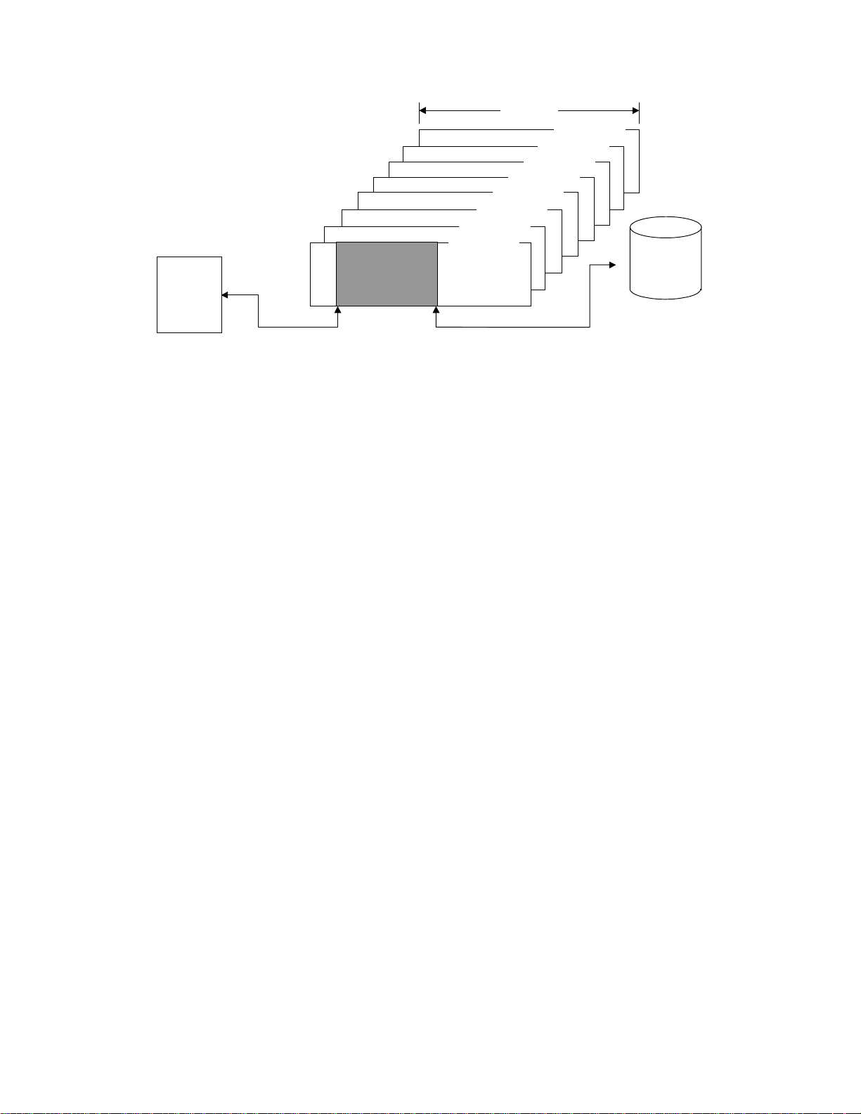
INIT
Figure 2.1 Data buffer configuration (in the case of 8 cache segments)
The basic functions and operations of the data buffer in a read operation and a write operation are
shown below.
(1) Read operation
Data read from the disk media are temporarily stored in the data buffer. Then, they are transferred
to the SCSI bus with the timing specified in the MODE SELECT parameter. The basic read
operation procedure is as shown below.
Write
Read
m
o
Valid Data
Segment 3
Segment 2
Segment 1
Segment 0
Segment
Segment 5
Segment 4
Write
m
Segment 7
Segment 6
Disk Media
o
Read
1) When the IDD receives a command, normally, it disconnects from the SCSI bus through
disconnect processing and locates the data block specified by the command where it is stored
on the disk media.
2) When the target data block has been located, the IDD reads the data form the disk media to the
data buffer. At this time, if a recoverable error is detected, the IDD performs error recovery
processing according to the specification in the MODE SELECT pa r amete r o r co r r ec ts the d at a
in the data buffer.
3) When the IDD has read the amount of data specified by the buffer full ratio in the MODE
SELECT paramete r (see S ection 2 .1.2) to the da ta buffer, it perfo rms reconne ction pr ocessing
with the SCSI bus and begins transferring data to the INIT (SCSI bus) from the data buffer
while continuing to read subsequent data blocks to the data buffer.
4) If the data transfer capacity of the INIT (SCSI bus) is high and the data buffer becomes empty
before completing transfer of the number of data blocks specified by the command, the IDD
performs disconnect processing at that point. Thereafter, reconnection, data transfer and
disconnection (the operations in 3) and 4) above) are repeated until all the data blocks
specified in the command have been transferred.
5) If the number of blocks specified in the command to be transferred is larger than the capacity
of a cache segment and if the data transfer rate of the INIT is lower than the data transfer rate
of the disk drive, the empty space in the data buffer disappears from step 3) and the IDD may
soon not be able to read data from the disk media (data overrun). In this case, the IDD
relocates the block that caused the data overrun after waiting one disk revolution, and
continues the reading process.
C141-E124-01EN2 - 2
Page 57

6) When transfer of all the specified data is completed, the IDD reports the status and terminates
the command.
Note:
In order to avoid frequent repetition of the disconnect/reconnect processing after data
transfer starts on the SCSI bus, and avoid the occurrence of data overruns, it is necessary
to set the buffer full ratio (see Secti on 2.1.2) of the MODE SELECT parameter so the
difference in the data transfer rates between the INIT (SCSI bus) and the disk drive is
maintained in a good balance.
Figure 2.2 shows an example of the data buffer operating state during a read operation. Details are
explained in Section 2.1.2.
Sector
Disk
Amount of Data
in the Buffer
Buffer Full Ratio
SCSI Bus
Figure 2.2 Example of data buffer operation during read
(2) Write operation
After data transferred from the INIT are stored temporarily in the data buffer, they are written to
the disk media. The basic write operation procedure is as shown below.
1) When the IDD receives a command and disconnects, it immediately reconnects and enters the
DATA OUT phase and stores data transferred from the INIT to the data buffer (data pre-fetch).
At this time, the IDD locates the position of the data block on the disk media specified by the
command in parallel.
When storing of all th e data specified in the command in the data buffer is completed, or if the empty
space in the data buffer is all filled during data storage due to the volume of the specified data, the
IDD performs discon nect processin g an d dis conn ects f rom th e SCSI bu s.
2) When locating of the target data block on the disk media is completed, the IDD writes the data
in the data buffer to the disk media. If the target data block location operation is completed
during the data pre-fetch processing in 1), writing of data to the disk media is performed in
parallel with the data pre-fetch to the data buffer.
DATA IN
Reconnection
Data Storage Completion Wait
C141-E124-01EN 2 - 3
Page 58

3) If the data transfer rate of the INIT (SCSI bus) is lower than the data transfer rate of the disk drive,
since the data pre-fetch of data that are to be written to that data block is not completed, it may not be
possible to write the data continuously to the disk (data underrun). In this case, the IDD waits one
disk revolution while continuing to pre-fetch data from the INIT, then repositions the block that
caused the data underrun and continues the w riting of data to the disk.
4) After disconnect processing, if all the blocks of data specified in the command have not yet
been transferred from the INIT, as writing of data to the disk media progresses, at the point
when the empty space in the data buffer reaches the amount specified in the buffer empty ratio
in the MODE SELECT parameter, the IDD performs reconnection processing and begins
transferring the succeeding data (data pre-fetch).
Writing of data to the disk media is performed in parallel and data transfer with the INIT continues
until the empty space in the data buffer is full or until transfer of all the data specified in the
command is completed. From then on, disconnection, reconnection and data transfer are repeated
until transfer of all the blocks of data specified in the comm and is com pleted.
5) When writing of all the specified data is completed, the IDD reports the status and terminates
the command.
Notes:
1. If the amount of transfer data specified in a command is smaller than the capacity of
the cache segment, all the data necessary for execution of the command are prefetched in a batch in the processing in 1) above, so the value specified in the buffer
empty ratio has not meaning.
2. If the amount of data processed with a single command exceeds the capacity of one cache
segment, in order to avoid frequent repetition of disconnect and reconnect processing
during command execution, and in order to escape the occurrence of data underrun, it is
necessary to set the buffer empty ratio (see Section 2.1.2) of the MODE SELECT
parameter so the difference in the data transfer rates between the INIT (SCSI bus) and the
disk drive is m aint ained i n a g ood balance.
Figure 2.3 shows an example of the data buffer operating state during a write operation.
Details are explained in section 2.1.2.
Sector
Disk
Amount of Data in the Buffer
SCSI
Bus
COMMAND
DATA OUT
ReconnectionDisconnection
STATUS
Figure 2.3 Example of data buffer operation during write
C141-E124-01EN2 - 4
Page 59

2.1.2 Operation mode setting
(1) M ODE SELECT par ameter
In order to make it possible to control from the INIT the reconnection processing start timing for
executing data transfers with the SCSI bus in read and write operations, the IDD is p rovided with the
MODE SELECT para meter (Disco nnect/Reco nnect Para meter: Page code = 2 ) shown in Figure 2.4 .
The user can set the optimum operating state in the system environment as necessary. The IDD holds
the MODE SELECT parameter individually for each INIT's SCSI ID, so the specified parameter
values can differ for each INIT. See Section 3.1.5 for details of th e MODE SELECT command.
[Disconnect/Reconnect Parameter (Page code = 2)]
Bit
Byte
0 00000010
1 X‘0E’ (Page Length)
2 Buffer Full Ratio
3 Buffer Empty Ratio
4
~
~
15
76543210
Default Value: X‘00’
Variable Range: X‘00’ to X‘FF’
Default Value: X‘00’
Variable Range: X‘00’ to X‘FF’
~
~
a. Buffer full ratio
(Other parameters)
Figure 2.4 Parameters for controlling reconnection timing
This parameter specifies the timing for the IDD to start reconnection to perform data transfer
to the INIT in a READ or READ EXTENDED command.
~
~
The value specified in this parameter (n) shows the amount of data read to the IDD's data
buffer from the disk media as a proportion [n/256] of the total capacity of the data buffer until
reconnection processing with the SCSI bus is started. (
If it is possible to transfer the amount of data specified in this parameter to the INIT from the
data buffer, reconnection processing is executed and transfer of data to the INIT begins.
However, if the total amount of transfer data specified in the command does not fill the
capacity of the cache segment, the IDD executes reconnection processing and begins
transferring data to the INIT when it becomes possible to transfer the amount of data blocks
from the data buffer which is equivalent to the proportion of the total volume of transfer data
blocks specified in the command that is specified by this parameter.
For example, if a read operation of 16 blocks with a logical data block length of 512 bytes (8
Kbytes) is requested, when the value specified in this parameter is 32, reconnection processing
C141-E124-01EN 2 - 5
Note
)
Page 60

is performed when it becomes possible to transfer 2 blocks of data [16 x (32/256)], from the
data buffer.
b. Buffer empty ratio
This parameter specifies the timing for the IDD to start reconnection when it is requested by
the INIT to transfer data in the WRITE, WRITE EXTENDED or WRITE AND VERIFY
command. In a write operation, after the IDD receives a command, the IDD begins transferring
data (data pre-fetch) while locating the position of the target data blocks on the disk media in
parallel. Therefore, if the total number of bytes of data specified in the command is less than
the capacity of a cache segment, all the data are pre-fetched in a batch, so the specification in
this parameter is not applied.
The value specified in this parameter (n) indicates a proportion of the total data buffer capacity
of the IDD when the buffer is empty [n/256]. (
While the IDD is writing data to the disk media, it is using the data pre-fetched to the data
buffer in order and when the empty space in the data buffer reaches the amount specified in
this parameter, it executes reconnection processing, requesting transfer of the succeeding data.
However, if the number of data blocks remaining to be transferred according to the command
being executed does not reach the amount of data specified in this parameter, the IDD executes
reconnection processing at the point when the number of data blocks remaining in the data
buffer's empty space reaches the specified number of data blocks and requests transfer of the
succeeding data.
Note
)
Note:
If the value specified for the "buffer full ratio" or the "buffer empty ratio" is not within
double the integral boundary of the logical data block length, the IDD rounds up the
specified value to the nearest data block boundary. In addition, if zero is specified for any
of these parameters, the IDD an appropriate value for the parameter that is determind by
IDD.
C141-E124-01EN2 - 6
Page 61

2.2 Look-Ahead Cache Feature
In order to use the data buffer more effectively and improve the disk drive's effective access speed,
the IDD is equipped with a simple cache feature called a "Look-Ahead Cache Feature." The LookAhead cache feature is an effective, simple cache function for an INIT which reads data block
groups on the disk media sequentially using multiple commands.
2.2.1 Caching operation
When the IDD is executing a READ command or a READ EXTENDED command, it reads the
requested data from the disk media and transfers it to the INIT while at the same time reading (looking
ahead at) data blocks which are s u bsequ en t to th e las t log ical data block s pecif ied in th at command to the
data buffer. Then, when a READ command or READ EXTENDED command issued later specifies any
of those Look-Ahead data blocks, the IDD transfers those data directly to the INIT from the data buffer
without accessing the disk media. In this way, when continuous logical data block groups are read
sequentially by multiple commands, mechanical access operations can be eliminated and effective access
time greatly reduced.
An INIT can prohibit the operation of this Look-Ahead cache feature by setting the caching
parameter described in section 2.2.2.
(1) Caching object commands
Commands which execute caching operations are the commands shown below:
READ
x
READ EXTENDED
x
If all the data block groups which are objects of the processing specified in these commands, or a
portion of the data blocks, including the top logical data block specified in these commands are
relevant data (See item (2)) for caching in the data buffer (if they hit), when the IDD receives a
command and performs disconnect processing, it immediately reconnects and sends the data on the
data buffer which can be transferred to the INIT. The caching operation can be disabled by the
FUA bit of the READ EXTENDED command. If "1" is specified in the FUA bit, the IDD reads
data from the disk media.
On the other hand, if the top logical data block specified in a command is not relevant data for
caching in the data buffer (if they miss), reading of data is performed from the disk media using the
old cache segment.
(2) Data which are objects of caching
Data which exist in the data buffer and which are objects of caching in item (1) (data which are not
accessed from the disk media but are transferred to the INIT from the data buffer) are as described
below.
a) Data read by a READ or a READ EXTENDED command and which have been read to the
data buffer by Look-Ahead are data which are objects of caching. Depending on the timing for
halting Look-Ahead, it is possible that data read by the READ command will be overwritten by
Look-Ahead.
C141-E124-01EN 2 - 7
Page 62

b) Data which have been hit by the READ or READ EXTENDED command and transferred to
the INIT once are also objects of caching as long as they are not invalidated.
c) Data transferred from the INIT and written to the disk media by the WRTTE and WRITE
EXTENDED command are objects of caching.
d) Data transferred from the INIT and written to the disk media by the WRITE AND VERIFY
command is not the objects of caching.
(3) Disabling caching data
Various data which are objects of caching in the data buffer are disabled in the following cases.
a) If any of the following commands is issued for the same data block as data which are the object
of caching, that data block ceases to be an object of caching.
WRITE
x
WRITE EXTENDED
x
b) If any of the following commands is issued, all the data which are objects of caching are
disabled.
CHANGE DEFINITION
x
LOG SELECT
x
MODE SELECT
x
MODE SENSE
x
PERSISTENT RSV IN
x
READ BUFFER
x
READ DEFECT DATA
x
READ LONG
x
RECEIVE DIAGNOSTIC RESULTS
x
REPORT DEV ID
x
SEND DIAGNOSTIC
x
START/STOP UNIT
x
WRITE LONG
x
c) If the data buffer where data which are objects of caching are stored is used by any of the
following commands, the data existing in that data buffer which are objects of caching are
disabled.
WRITE AND VERIFY
x
FORMAT UNIT
x
LOG SENSE
x
MODE SELECT EXTENDED
x
MODE SENSE EXTENDED
x
PERSISTENT RSV OUT
x
READ CAPACITY
x
READ DEFECT DATA (12)
x
REASSIGN BLOCKS
x
RELEASE EXTENDED
x
RESERVE EXTENDED
x
SET DEV ID
x
WRITE BUFFER
x
WRITE SAME
x
READ
x
READ EXTENDED
x
WRITE
x
d) If any of the following events occurs, all the data which are objects of caching are disabled.
A RESET condition occurs on the SCSI bus.
x
A TARGET RESET message is issued by any INIT.
x
C141-E124-01EN2 - 8
WRITE EXTENDED
x
WRITE AND VERIFY
x
VERIFY
x
Page 63

2.2.2 Caching parameters
The IDD supports the MODE SELECT pa rameters (caching parameters: page code = 8) shown in
Figure 2.5 for controlling the cache feature. See Section 4.1 concerning details of the MODE
SELECT parameters.
[Caching Parameters (Page Code = 8)]
Bit
Byte
0 00001000
1
2 IC ABPF CAP DISC SIZE WCE MS RCD
Default 00000100
Variable10000101
3 X‘00’ (Reserved)
4-5 Prefetch-suppressed block count
Default X‘FFFF’
Variable X‘0000’
6-7 Minimum prefetch
Default X‘0000’
Variable X‘0000’
8-9 Maximum prefetch
Default X‘00xx’
Variable X‘0000’
10-11
Default X‘FFFF’
Variable X‘0000’
12 FSW LBCSS DRA VS VS Reserved
Default 10000000
Variable00000000
13
Default X‘10’
Variable X‘3F’
14-15
Default X‘0008’
Variable X‘0000’
16 X‘00’ (Reserved)
17-19
Default X‘000008’
Variable X‘000000’
76543210
X‘0A’ or X‘12’ (
Page Length
Maximum prefetch
limit block count
Cache segment count
Cache segment size
Non cache buffer size
)
Remark:
The variable column indicates whether the parameter can be changed or not (if "1", the
parameter can be changed).
Figure 2.5 Cache control parameters
C141-E124-01EN 2 - 9
Page 64

2.2.3 Look-Ahead operation, Look-Ahead volume
1) Excluding the conditions in 3) and 4) for the amount of data specified as the minimum prefetch volume, data are read for look-ahead irrespective of track boundaries or cylinder
boundaries. Commands which are already in the queue or commands which are newly
received while a look-ahead operation is in progress, are executed after the look-ahead
operation is completed. However, if the new command is a READ or READ EXTENDED
command, and it is a command in which the first specified logical data block is a sequential
access data block, the command is executed without the look-ahead operation being halted.
When a newly received command is a command which is not the object of caching, that
command is executed immediately in parallel with a look-ahead operation.
Also, in the case of a command which disables all data which are objects of caching (see
Section 2.2.1 (3)), the look-ahead operation is halted and that command is executed
immediately.
2) When commands exist in the queue, the look-ahead operation is halted at the point when
reading of the specified amount of data at the minimum pre-fetch volume is completed, then
execution of the new command starts. When there are no commands that need to be newly
executed, the data look-ahead operation is continued, even after the volume of data specified as
the minimum amount of pre-fetch data have been read, until one of the following conditions,
1), 3) or 4), occurs.
When "1" is specified in the DISC bit, if look-ahead of data equal in volume to a cache
x
segment is completed.
When "0" is specified in the DISC bit, if look-ahead of all the data is completed up to the
x
track boundary or the cylinder boundary.
3) During a data look-ahead operation, when any error occurs, the data look-ahead operation is
terminated at that point (retry is not executed).
4) When a RESET condition occurs on the SCSI bus, or when any INIT issues a TARGET
RESET message, the look-ahead operation is terminated at that point and all the look-ahead
data stored in the data buffer are invalidated.
5) During a look-ahead operation, if "sector slip processing" is applied, or defective sectors exist
in the same cylinder to which "alternate processing" is applicab le, the look-ahead operation is
continued without interruption.
C141-E124-01EN2 - 10
Page 65

2.3 Write Cache
The IDD is equipped with a write cache function in order to reduce the INIT's command
processing time. If that operation is permitted by the MODE SELECT command (caching
parameters: Page code = 8, WCE bit), at the point when the IDD completes the transfer of all data
specified in the WRITE or WRITE EXTENDED command, it reports the GOOD status and
terminates the command.
Note:
If the write cache function is permitted, data transferred form the INIT by a WRITE or WRITE
EXTENDED command are written to the disk media after the GOOD status is reported, so
when an unrecoverable write error is detected in that write operation, sense data is generated.
When those sense data is being held, the IDD ordinarily responds to the command that is
executed next by a "CHECK" status (deferred error), notifying the INIT that sense data is
being held. However, ordinarily, it is troublesome for the INIT to retry when there is an
unrecoverable error in a write cache operation, so adequate caution should be exercised when
using this function.
C141-E124-01EN 2 - 11
Page 66
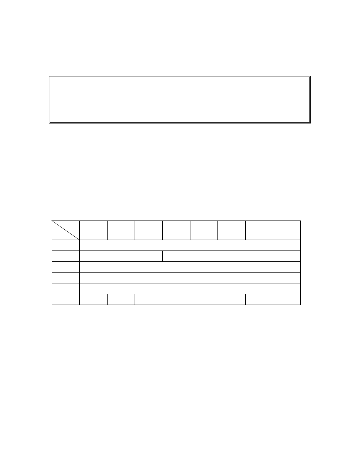
CHAPTER 3 COMMAND SPECIFICATIONS
3.1 Control/Sense Commands
3.2 Data Access Commands
3.3 Format Comman ds
3.4 Maintenance, Diagnostic Commands
This chapter describes detailed specifications of the SCSI commands which the IDD is equipped with and
how to use them.
3.1 Control/Sense Commands
3.1.1 TEST UNIT READY (00)
Bit
Byte
0 X‘00’
1 LUN 00000
200000000
300000000
400000000
5000000FlagLink
This command checks the status of the disk drive. This command is executed immediately without
queueing in a system which issues only commands with no tags or links.
If the IDD is in the ready state and it is possible for it to be used by the application client which
issues this command, a GOOD status is reported for this command.
If the IDD is not in the ready state, it reports a CHECK CONDITION status for this command.
The sense data generated at this time indicate the IDD's state at this time.
76543210
C141-E124-01EN 3 - 1
Page 67

3.1.2 INQUIRY (12)
Bit
Byte
0 X‘12’
1LUN000CmdDtEVPD
2 Page Code/Operation Cpde
300000000
4 Transfer Byte Length
5000000FlagLink
This command transfers the information showing the IDD's characteristics (INQUIRY data) to the
application client. This command is executed immediately without queuing in a system which
issues only commands with no tags or links.
This command is executed normally even in cases where the UNIT ATTENTION condition is
held, and the UNIT ATTENTION condition is not cleared. This command is also executed
normally when the disk drive is not in the ready state or even when an illegal logical unit number
(LUN) is specified.
A CHECK CONDITION status is reported for this command and it is terminated abnormally only
in the case that one of the following conditions is detected.
76543210
x There is an error in the specifications other than the LUN field of the CDB.
x It is impossible to send INQUIRY data because of an IDD hardware error.
x An unrecoverable error was detected on the SCSI bus.
x An error detected during command execution was recovered in the IDD's error recovery
processing (Retry), but the mode which reports "RECOVERED ERROR" is specified in the
MODE SELECT p arameter.
x Applicability to overlapping command exception conditions (See Section 1.7.1.)
The functions which can be specified in this command's CDB and the contents of information
transferred to the application client from the IDD differ depending on the specifications in the
CHANGE DEFINITION command. Furthermore, see Section 3.1.4, "CHANGE DEFINITION
(40)" concerning the CHANGE DEFINITION command.
C141-E124-01EN3 - 2
Page 68

If bytes 1, the "EVPD (enable vital product data)" bits, the "CmdDt (Command Support Data)"
bits, and byte 2, the "Page code" field in the CDB are enabled only in the case that transfer of the
SCSI-2/SCSI-3 mode's INQUIRY data is specified. In the case of the SCSI-1/CCS mode, zero
must be set in these bits and in this field. And if both the "EVPD" and "CmdDt" bits are one, this
command is terminated by a CHECK CONDITION status (ILLEGAL REQUEST [=5] / Invalid
Field in CDB [=24-00]).
(1) EVPD (Enable Vital Product Data)
a) If the specification in this bits is zero, the IDD transfers the standard INQUIRY data or the
command supported data, mentioned later, to the application client.
b) If the specification in this bits is one, product information called VPD (vital product data) is
transferred to the application client.
(2) CmdDt (Command Supported Data)
a) If the specification in this bits is zero, the IDD transfers the standard INQUIRY data,
mentioned later, to the application client.
b) If the specification in this bits is one, the IDD transfers the command supported data,
mentioned later, to the application client.
(3) Page code / Operation code
a) When the "EVPD" bits is one, this field specifies that the IDD transfers the kind of the VPD
information.
b) If the "EVPD" bit is zero and the "CmdDt" bits is one, this field specifies the operation code
(CDB byte 0) of commands generated command supported data.
(4) Transfer Byte Length
Byte 4 of the CDB, the "Transfer Byte Length" field, shows the number of bytes of standard
INQUIRY data or VPD information that the application client can receive by this command.
The IDD transfers data with the byte length specified in the "Transfer Byte Length" field, or the
byte length in the standard INQUIRY data or VPD information which it is holding, whichever has
the smallest number of bytes, to the application client. When zero is specified in the "Transfer
Byte Length" field, this command is normally terminated without anything being transferred.
(5) Standard INQUIRY data
Figure 3.1 shows the format and contents of the standard INQUIRY data transferred to the INIT by
this command if "0" is specified in the "EVPD" and the “CmdDt” bit.
C141-E124-01EN 3 - 3
Page 69
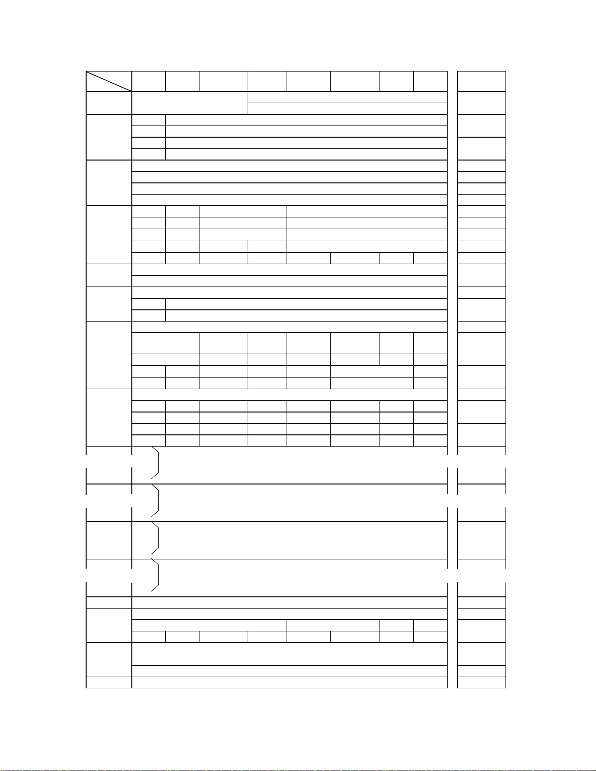
Bit
Byte
1
2
3
5
6
7
8
~
9
~
15
16
17
~
~
31
32
33
34
35
36
~
37
~
47
48-55 X‘00’ (Vendor Specific)
56
57 X‘00’ (Reserved)
56-73
74-95 X‘00’ (Reserved)
76 5 4 3 2 10
Qualifier Device Type Code0
(0, 0, 0) or (0, 1, 1) (0, 0, 0, 0, 0) or (1, 1, 1, 1, 1)
RMB Reserved
00 0 0 0 0 00
RMB Device Type Code
00 0 0 0 0 00
Version
X’ 01’ (SCSI-1)
X’ 02’ (SCSI-2)
X’ 03’ (SPC) or X’ 04’ (SPC-2)
AENC TrmIOP Response Data Format
00 0 0 0 0 01
01 0 0 0 0 10
AERC Obsolete
00 0 0 0 0 10
01 0 1 1 0 11
00 0 0 0 0 00
SCCS Reserved
00 0 0 0 0 00
00 0 0 0 0 00
(Reserved) Port DualP
00 0/1 0 0 0 00/1
BQue EncServ VS MultiP
00 0 0 0 0 00/1
00 0 0 0 0 00
RelAdr WBus32 WBus16 Sync Linked TTD CmdQue SftRe
00 0/1 1 1 1 10
RelAdr Obsolete Wbus16 Sync Linked TranDis CmdQue VS
00 0/1 1 1 1 10
~
~
~
~
~
~
FUJITSU
(Vendor ID: ASCII)
(Product ID: ASCII)
Microcode Version No. (ASCII)
(Product Revision: ASCII)
Device Serial No. (ASCII)
00 0 0 0/1 0/1 00
NORMACA
Reserved CLOCKING QAS IUS
HISUP Response Data Format
Additional Data Length4
MCHNGR
X‘00’ (Reserved)
X‘00’ (Reserved)
Version Descriptor
Figure 3.1 Standard INQUIRY data
ACKB
REQB
Addr32 Addr16
Obsolete Addr16
SCSI mode
SCSI-1/CCS
SCSI-1/CCS
SCSI-1/CCS
CCS/SCSI-2
SCSI-1/CCS
SCSI-1/CCS
~
~
~
~
~
~
~
~
~
~
~
~
CCS/SCSI-2
CCS/SCSI-2
----
SCSI-3
SCSI-2
----
SCSI-2
SCSI-3
----
SCSI-2
----
SCSI-3
SCSI-3
SCSI-2
SCSI-3
SCSI-2
SCSI-3
----
----
SCSI-3
SCSI-3
~
~
~
~
~
~
C141-E124-01EN3 - 4
Page 70

a. Qualifier field
(0,0,0): The specified logical unit shows the type of input/output device shown in the "Device
Type Code" field. Even if this code is reported, it does not mean that that logical unit
is in the ready state.
(0,0,1): The specified logical unit shows the type of input/output device shown in the "Device
Type Code" field, but it shows that an actual input/output device is not connected to
that logical unit. The IDD does not report this code.
(0,1,1): Shows that the specified logical unit is not supported. When this code is reported, it X
'1F' is shown in the "Device Type Code" field.
b. Device type code
(0,0,0,0,0): Direct access device
(1,1,1,1,1): Undefined device
When LUN=0 is specified, the IDD reports "(0,0,0,0,0) : direct access device" as the device
type code. At this time, the "Qualifier" field is "(0,0,0)." Therefore, byte 0 indicates X '00.'
On the other hand, when a LUN other than "0" is specified, the IDD reports "(1,1,1,1,1) :
undefined device" as the device type code. At this time, the "Qualifier" field is "(0,1,1)."
Therefore, byte 0 indicates X '7F.'
c. RMB bit
When this bit is "1," it indicates that the storage media is a removable disk device. The IDD is
a fixed disk device, so this bit is always reported as "0."
d. Version
The VERSION field indicates the implemented version of this standard and is defined below.
Code Description
X'01' ANSI X3.131: 1986 (SCSI-1)
X'02' ANSI X3.131: 1994 (SCSI-2)
X'03' ANSI X3.301: 1997 (SPC Rev.11)
X'04' T10/1236-D (SPC-2)
e. Response data format field
This field shows the code which shows the standard INQUIRY data format. The definition of
the code is (0,0,0,1) for SCSI-1/CCS mode or (0,0,1,0) for SCSI-2 or SCSI-3 mode.
C141-E124-01EN 3 - 5
Page 71

f. Additional data length
This field shows the length of the INQUIRY data (byte length) after byte 5. This value shows the
length in the INQUIRY data held by the IDD without relation to the specification in the transfer byte
length field i n th e CDB, an d is al w ay s X‘ 5B’ (total data leng th = 96 by tes).
g. Supported functions
The bit positions shown below are valid only when the CHANGE DEFINITION command is
set so that the SCSI-2 or SCSI-3 mode INQUIRY data are transferred, and the functions which
the IDD supports are shown in the bit correspondence.
"1" indicates that that function is supported and "0" indicates that that function is not
supported. When the CHANGE DEFINITION command is not set so that SCSI-2 mode
INQUIRY data are transferred, "0" is displayed in all these bit positions.
x SCSI-3 mode
[Byte 3]
- AERC (Asynchronous event reporting capability):
Asynchronous condition notify function [0]
- NORMACA (Normal ACA supported):
ACA support [0]
- HISUP (Hierarchical support):
Defined the hierarchical addressing model to assign LUN [0]
[Byte 5]
- SCCS (SCC support):
Embedded storage array controller equipment [0]
[Byte 6]
- BQue (Basic queuing):
Combination with CMDQUE [0]
- EncServ (Enclosure service):
Enclosure service [0]
- MultiP (Multi port):
Supported multi-port [0]
- MChngr (Medi um cha nger):
Medium Changer [0]
- Addr16 (Wide SCSI address 16):
16 bit SCSI addressing [0/1]
[Byte 7]
- RelAdr (Relative addressing):
Relative logical block addressing [0]
- WBus16 (16-bit wide data transfer):
Data transfer on a 2-byte bus [0/1]
- Sync (Synchronous data transfer):
Data transfer on the synchronous mode [1]
- Linked (Linnked command):
Command link function [1]
- TranDis (Transfer disable):
Continue task and target transfer disable message [1]
- CmdQue (Command queuing) :
Command queuing function [ 1]
C141-E124-01EN3 - 6
Page 72

Bque CmdQue Description
0 0 No command queuing of any kink supported
0 1 Command queuing with all types of task tags supported
1 0 Basic task set model supported
1 1 Illegal combination of BQue and CmdQue bits
- VS (Vendor specific):
Not defined [0]
x SCSI-2 mode
[Byte 3]
- AENC (Asynchronous event notification capability):
Asynchronous condition notify function [0]
- Tr mIOP (Terminate I/ O process):
TERMINATE I/O PROCESS message [0]
[Byte 6]
- DualP (Dual port):
Dual port function [0]
- Port:
Connection port, '0'= connect to port A [0]
'1'= connect to port B
- ACKBREQB (ACKB/REQB):
Use the ACKB and REQB signals with the B cable or the Q cable [0]
- Addr32 (Wide SCSI address 32):
32 bit SCSI addressing [0]
- Addr16 (Wide SCSI address 16):
16 bit SCSI addressing [0/1]
[Byte 7]
- RelAdr (Relative addressing):
Relative logical block addressing [0]
- WBus32 (32-bit wide data transfer):
Data transfer on a 4-byte bus [0]
- WBus16 (16-bit wide data transfer):
Data transfer on a 2-byte bus [0/1]
- Sync (Scychronous data transfer
Data transfer in the synchronous mode [1]
- Linked (Linked command):
Command link function [1]
- TTD (Target transfer disable):
Target transfer disable message [1]
- CmdQue (Command queuing) :
Tagged command queuing feature [1]
- SftRe (Soft Reset):
Soft reset condition [0]
h. Vendor ID field
This field indicates the name of the product's supplier in left-justified ASCII code, and always
indicates FUJITSU. The unused right end is space fo r the ASCII code.
C141-E124-01EN 3 - 7
Page 73

i. Product ID field
The product's model name is displayed in left-justified ASCII code in this field.
j. Product Revision field
The IDD's microcode version number is displayed in ASCII code in this field.
k. Device Serial Number field
The value following byte 4 of the device serial number in the VPD information is indicated in
this field. Higher order digits which do not contain valid numbers are filled with ASCII code
spaces (X '20').
l. Clocking field
This field indicates the code which shows the clocking method. The definition of the code is as
shown below.
"Clocking" Bit 3 2 Description
0 0 Indicates the device server supports only ST
0 1 Indicates the device server supports only DT
10Reserved
1 1 Indicates the device server supports ST and DT
m. QAS (Quick Arbitrate Supported) bit
This bit of one indicates that the device server supports the quick arbitrate feature. A value of
zero indicates that the device server does not support the quick arbitrate feature.
n. IUS (Information unit supported) bit
This bit of one indicates that the device server supports information units. A value of zero
indicates that the device server does not support information units.
o. Version Descriptor field
This field is provided for identifying upto eight standards to which the Device claims
conformance.
The IDD shall be indicated as shown below.
C141-E124-01EN3 - 8
Page 74

BYTE Code Description
58 to 59 OX00, OX40 SAM2
60 to 61 OX0B, OX18 SPI3 T10/1302D rev10
62 to 63 OX01, 0X3C SPC ANSI X3.301: 1997
64 to 65 OXS01, OX9B SBC T10/0996 rev08C
66 to 67 OX00, OX00 68 to 69 OX00, OX00 70 to 71 OX00, OX00 72 to 73 OX00, OX00 -
(6) Command Support Data
Figure 3.2 shows the format and contents of the command support data transferred to the INIT by
this command if "0" is specified in the "EVPD" bit and "1" is specified in the "CmdDt" bit.
Bit
Byte
0 Qualifier Device Type Code
100000 Support
2Version
3 X'00' (Reserved)
4 X'00' (Reserved)
5 CDB Size (m-5)
6
~ ~ ~
m
a. Qualifier, Device Type Code, Version
76543210
CDB Usage Data
Figure 3.2 Command support data
These fields are the same as those in the previously mentioned standard INQUIRY data.
C141-E124-01EN 3 - 9
Page 75

b. Support
This field indicates the value defined below.
"Support" Bit 2 1 0 Description
0 0 0 Data about the requested SCSI operation code is not currently
available.
0 0 1 The device server does not support the tested SCSI operation
code. All data after byte 1 is undefined.
010Reserved
0 1 1 The device server supports the tested SCSI operation code in
conformance with an SCSI standard.
1 0 0 Vendor-specific (undefined)
1 0 1 The device server supports the tested SCSI operation code in a
vendor-specific manner.
1 1 0 Vendor-specific (undefined)
111Reserved
If the "Support" field contains "000b", all data after byte 1 is not valid. One possible reason
for "support" being "000b" is the device server's inability to retrieve information stored on the
media. When this is the case, a subsequent request for command support data may be
successful.
c. CDB size
This field contains the number of bytes in the CDB for the operation code being queried, and
the size of the "CDB Usage Data" field in the return data.
d. CDB usage data
This field contains information about the CDB for the operation code being queried. The first
byte of the "CDB usage data" contains the operation code for the operation being queried. All
bytes except the first byte of the "CDB usage data" contains a usage map for bits in the CDB
for the operation code being queried.
The bits in the "Usage map" have a one-for-one correspondence to the CDB for the operation
code being queried. If the device server evaluates a bit as all or part of a field in the CDB for
the operation code being queried, the usage map contains a one in the corresponding bit
position. If the device server ignores or treats as reserved a bit in the CDB for the operation
code being queried, the usage map contains a zero in the corresponding bit position. The
usage map bits for a given CDB field a l l have the same value.
Thus, the CDB usage bit map for this command for a device server that implements command
support data but not vital product data is: 12h, 02h, FFh, 00h, 07h.
C141-E124-01EN3 - 10
Page 76

(7) VPD information
When "1" is specified in the "EVPD" bits of the CDB, the VP D information described below is
transferred to the INIT by this command. The INIT specifies the type of VPD information
required in the "Page code" field of the CDB. The type of VPD information supported by the IDD
and its page code number are as shown below.
Page Code Page (Hex) Function
00 Page code list of supported VPD information
80 Device serial number
C0 Operation mode
Furthermore, if page codes other than those shown above (VPD information that is not supported
by the IDD) are specified in the CDB, that command is terminated with a CHECK CONDITION
status (ILLEGAL REQUEST [=5] / Invalid field in CBD [=24-0 0]).
The format and contents of each type of VPD information are shown below.
a. Page code list
This VPD information reports the page code list of VPD information supported by the IDD.
The format of this VPD information is shown in Figure 3.3.
Bit
Byte
0 Qualifier Device Type Code
1 X‘00’ (Page Code)
2 X‘00’
3 X‘03’ (Page Lengt h)
4 X‘00’ (Page Code List)
5 X‘80’ (Device Serial No.)
6 X‘C0’ (Operation Mode)
76543210
Figure 3.3 VPD information: VPD identifier list
The values indicated in the "Qualifier" and "Device Type Code" fields in byte 0 are the same
as those in the previously mentioned standard INQUIRY data. The "Page code" field in byte 1
indicates the page code (X '00') of this VPD information itself. Also, the "Page length" field in
byte 3 indicates the length (byte length) after byte 4. This value has no relationship to the
specification in the "Transfer Byte Length" in the CDB, but indicates the length of this VPD
information and is always X '03' (Total data length = 7 bytes).
C141-E124-01EN 3 - 11
Page 77

Byte 4 and subsequent bytes list all the VPD information page codes supported by the IDD,
with the VPD page code indicated in ascending order in each byte.
b. Device serial No.
This VPD information reports the device serial number of the IDD. The format of this VPD
information is shown in Figure 3.4.
Bit
Byte
0 Qualifier Device Type Code
1 X‘80’ (Page Code)
2 X‘00’
3 X‘0C’ (Page Length)
4
5
~
~
15
76543210
~
~
The values indicated in the "Qualifier" and "Device Type Code" fields in byte 0 are the same
as those in the previously mentioned standard INQUIRY data. The "Page code" field in byte 1
indicates the page code (X '80') of this VPD information itself. Also, the "Page length" field in
byte 3 indicates the length (byte length) after byte 4. This value has no relationship to the
specification in the "Transfer Byte Length" in the CDB, but indicates the length of this VPD
information and is always X '0C' (Total data length = 16 bytes).
Device Serial No. (ASCII)
Figure 3.4 VPD information: device serial No.
~
~
Bytes 4 to 15 indicate the IDD's device serial number in right-justified decimal (ASCII code).
C141-E124-01EN3 - 12
Page 78

c. Operation mode
This VPD information reports the IDD's current operation mode. The format of this VPD
information is shown in Figure 3.5.
Bit
Byte
0 Qualifier Device Type Code
1 X‘C0’ (Page Code)
2 X‘00’
3 X‘04’ (Page Lengt h)
4 0 0 0 WDTR UNTAIN SDTR RSRTY 0
5 PHSCRC AGD ACE 0 0 0 RTD
6 X‘xx’ (Spindle Motor Start Delay Timing)
7 X‘00’ (Reserved)
76543210
Figure 3.5 VPD information: operation mode
The values indicated in the "Qualifier" and "Device Type Code" fields in byte 0 are the same
as those in the previously mentioned standard INQUIRY data. The "Page code" field in byte 1
indicates the page code (X 'C0') of this VPD information itself. Also, the "Page length" field
in byte 3 indicates the length (byte length) after byte 4. This value has no relationship to the
specification in the "Transfer Byte Length" in the CDB, but indicates the length of this VPD
information and is always X '04' (Total data length = 8 bytes).
Byte 4 and subsequent bytes list all the VPD information page modes currently set in the IDD.
This operation mode setting is performed by the CHANGE DEFINITION command, described
in Section 3.1.4, and Section 3.1.4 shows concerning a detailed definition of each bit.
C141-E124-01EN 3 - 13
Page 79

3.1.3 READ CAPACITY (25)
Bit
Byte
0 X‘25’
1 LUN 00000
2 Logical Block Address (MSB)
3 Logical Block Address
4 Logical Block Address
5 Logical Block Address (LSB)
600000000
700000000
80000000PMI
9000000FlagLink
This command transfers information related to the disk drive's capacity and the data block size to
the INIT.
When bit 0 "PMI (partial medium indicator)" of CDB byte 8 is "0," the logical block address and
block length (byte length) of the final data block which is accessible in the disk drive (user space)
are transferred to the INIT. At this time, the "Logical Block address" field in the CDB must
specify zero.
76543210
When the "PMI" bit is "1," the logical block address and block length (byte length) of data blocks
which satisfy either of the following conditions is transferred to the INIT.
x The data block on the cylinder where the specified block exists, which is just before the block
where the first alternate sector processing (not including defective block sector slip processing)
is implemented. However, when alternate sector processing is being implemented in the
specified block, the data block specified in the CDB.
x When no alternate sector processed data block exists in the cylinder where the specified block
exists, the last data block in that cylinder.
C141-E124-01EN3 - 14
Page 80

By using this command with the "PMI" bit specified as "1", the INIT can search for usable data
space continuously without being interrupted by data transfers for alternate sector processing or
switching of cylinders.
The format of the data transferred to the INIT by this command is shown in Figure 3.6.
Bit
Byte
0 Logical Block Address (MSB)
1 Logical Block Address
2 Logical Block Address
3 Logical Block Address (LSB)
4 Block Length ( MSB)
5 Block Length
6 Block Length
7 Block Length ( LSB)
76543210
Figure 3.6 READ CAPACITY data
C141-E124-01EN 3 - 15
Page 81
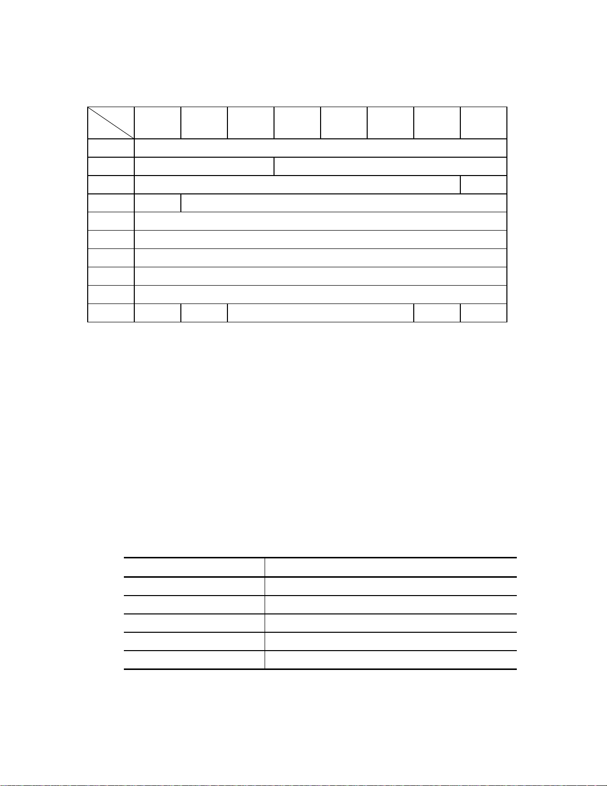
3.1.4 CHANGE DEFINITION (40)
Bit
Byte
0 X‘40’
1 LUN 00000
20000000Save
3 0 SCSI Level
400000000
500000000
600000000
700000000
8 Parameter List Length
9000000FlagLink
This command changes the IDD's SCSI level and the operation mode.
The INIT can know the SCSI level and operation mode that the IDD is currently using by the
INQUIRY command (Standard Inquiry Data and VPD Information - Operation Mode Page: Page
code X 'C0').
76543210
If the "Save" bit of CDB byte 2 specifies "1," the IDD saves the SCSI level and operation mode
specified in this command in the Boot-ROM (Flash ROM) when the command is executed.
If this bit specifies "0," the changes are not saved.
This command specifies a different SCSI level in the "SCSI level" field in SCB byte 3. The SCSI
level is indicated by 1 byte of code as shown in the following table. If a code other than the
following codes is specified, the command is terminated by a CHECK CONDITION status
(ILLEGAL REQUEST [=5] / Invalid field in CDB [=24-00] and the SCSI level and operation
mode are not changed.
Operation Code (HEX) SCSI Level
X'00' Not Change
X'01' SCSI-1 (Same as CCS)
X'02' CCS (Same as SCSI-1)
X'03' SCSI-2
*1 X'04' SCSI-3
*1 Set at shipping time.
C141-E124-01EN3 - 16
Page 82

If zero is specified in the "SCSI Level" field, the IDD operates at the current SCSI level without
changing the SCSI level. However, if the correct operation mode parameter (described later) is
transferred at the same time, the IDD changes its operation mode.
The total byte length of the operation mode parameter transferred by the INIT with this command
is specified in the "Parameter List Length" field in CDB byte 8.
If zero is specified in the "Parameter List Length" field, the command is terminated normally with
only the SCSI level being changed.
When changing the operation mode, the "Parameter List Length" field must always be specified by
the length (=8) defined by the operation parameter, described later. If a value other than the
defined length in the "Parameter Byte Length" field is specified, this command is terminated with a
CHECK CONDITION status (ILLEGAL REQUEST [=5 ] / I nvalid field in CDB [ =2 4-0 0] ) and the
SCSI level and operation mode are not changed.
If the IDD's operation mode is changed by this command, a UNIT ATTENTION conditio n (UNIT
ATTENTION [=6] / INQUIRY Data has changed [=3F-00]) is generated for all the INITs except
the INIT that issued this command.
The format for the operation mode parameter transferred by this command from the INIT to the
IDD is shown below. If the operation mode parameter is transferred in a format other than that
shown below, this command is terminated with a CHECK CONDITION status (ILLEGAL
REQUEST [=5] / Invalid field in parameter list [=26-00]) and the SCSI level and operation mode
are not changed.
Bit
Byte
76543210
0 X‘00’
1 X‘00’
2 X‘00’
3 X‘04’ (Parameter Length)
4000WDTR
UNTAIN
SDTR RSRTY 0
5 PHSCRC AGD ACE 0 0 0 RTD
6 X‘xx’ (Spindle Motor Start Delay Time)
7 X‘00’ (Reserved)
The operation mode parameter is configured from a 4-byte parameter list following a 4-byte
header.
Header
Parameter
List
C141-E124-01EN 3 - 17
Page 83

(1) Header
a) Bytes 0 to 2
X '00' must be specified in this field.
b) Parameter length
The parameter list length in byte 4 and subsequent bytes which follows the header must be
specified in this field. The parameter list length supported by the IDD is X '04' and the INIT
must not specify a value other than X '04' in this field. If a value other than X '04' is specified,
this command is terminated with a CHECK CONDITION status (ILLEGAL REQUEST [=5] /
Invalid field in parameter list [=26-00]) and the operation mode are not changed.
(2) Parameter list
a) WDTR (wide data transfer request: Effective for 16-bit SCSI devices only.)
This specifies whether or not a wide mode data transfer request from the IDD is permitted.
If this bit is set to 1, also set SDTR to 1. If only this bit is set but SDTR is not set, error code
5-26-00 is returned.
"1" (Permitted): After the power is switched on, after a RESET condition occurs or when the
first command is received following reception of a BUS DEVICE RESET
message, if a WIDE DATA TRANSFER REQUEST (WDTR) message is
not sent by the INIT, the IDD sends the WDTR message and attempts to
establish wide mode data transfer.
"0"* (Prohibited): If it is necessary to establish wide mode data transfer, the IDD does not
send the WDTR message. However, if the I NI T send s the W DT R message,
the IDD responds normally.
* Set at shipping time
b) UNTATN (UNIT ATTENTION report mode)
This specifies the response method to commands received from the INIT when the IDD is
holding a UNIT ATTENTION condition:
"1"* (Report): The IDD reports a CHECK CONDITION status (Standard SCSI
specification) in response to commands other than INQUIRY and
REQUEST SENSE.
"0" (No Report): The IDD terminates all commands that are received normally. (A CHECK
CONDITION status which causes a UNIT ATTENTION condition is not
reported.)
* Set at shipping time
C141-E124-01EN3 - 18
Page 84

c) SDTR (synchronous data transfer request)
Specifies whether or not it is permitted for the TARG to request a synchronous mode data
transfer.
"1" (Permitted) : After the power is switched on, after a RESET condition occurs or when the
first command is received following reception of a BUS DEVICE RESET
message, if a SYNCHRONOUS DATA TRANSFER REQUEST (SDTR)
message is not sent by the INIT, the IDD sends the SDTR message and
attempts to establish synchronous mode data transfer.
"0"* (Prohibited): Even if it is necessary to establish synchronous mode data transfer, no
SDTR message is sent from the IDD. However, if a SDT R message is sent
from the INIT, the IDD responds normally.
* Set at shipping time
d) RSRTY (reselection retry)
This specifi es the number of retries in the RESELECTI ON phase.
"1" *: Unlimited
"0": 10 times
* Set at shipping time
e) PHSCRC (Phase CRC)
This bit specifies where send or receive the CRC bytes in the DT Data IN/OUT transfer.
"1" (Phase): After the all transfer is terminated or before the phase during data transfer
changes other phase, the CRC bytes are sent or rec i eved.
"0"* (Block): The CRC bytes are sent or recieved in each block boundary.
* Set at shipping time
f) ACE (AIP checking enabled)
This specifies whether or not it is permitted to check AIP (Asynchronous Information
Protection).
"1" (Permitted): Permitting check
"0"*(Prohibited): Prohibiting check
* Set at shipping time
C141-E124-01EN 3 - 19
Page 85

g) AGD ( AIP generation disabled)
This specifies whether or not it is permitted to generate AIP (Asynchronous Information
Protection).
"1" (Prohibited): P ro hibited generation
"0"*(Permitted): Permitted generation
* Set at shipping time
h) RTD (reselection timeout delay)
This specifies the reselection timeout delay time.
Bit 1 Bit 0 Reselection Time-out Delay
0 0 250 [ms]*
0 1 3 [ms]
10Reserved
11Reserved
* Set at shipping time
i) Spindle motor start delay time
This specifies the time after power on until the motor starts.
The IDD's motor starts after [(value specified in this parameter) x (IDD's SCSI ID x 0.1)] seconds
from the power is switched on. If X '00' is specified in this parameter, the motor starts immediately
after the power is switched on, no matter what SCSI ID is set in the IDD. Also, the IDD starts the
motor immediately n o matter w h at value is specif ied in this param eter.
This parameter is enabled only when set in the "Auto Motor Start Mode" with a setting
terminal.
C141-E124-01EN3 - 20
Page 86

3.1.5 MODE SELECT (15)
Bit
Byte
0 X‘15’
1 LUN PF000SP
200000000
300000000
4 Parameter List Length
5000000FlagLink
This command performs setting and changing of each type of parameter related to disk drive
physical attributes, data format, timing of SCSI bus disconnect/reconnect processing and error
recovery procedures, etc. The INIT can know the types of parameters, the current settings of each
parameter and the types of parameters which can be changed, and the ranges for such changes, etc.
by using the MODE SENSE or MODE SENSE EXTENDED command.
The data (MO DE SELECT parameters) tr ansferred from the IN IT to the IDD b y this command,
are configured from a "Header," "B lock Descriptor" and one or more "Page Descriptors" which
describe each parameter, each of which will be explained later.
When the "P F ( p a ge fo r mat) " b it in CD B byte 1 i s " 1 , " i t ind i ca te s tha t t he M O DE SELECT parameter s
transferred from the INIT by th is command are in the "Page Descriptor" format. The IDD disregards the
value specified in this bit and regards the MODE SELECT parameters transferred from the INIT as being
in the "Page Descriptor" format and executes this com m an d.
76543210
The "SP (save pages)" bit in CDB byte 1 specifies whether o r not to save the MODE SELECT
parameters specified in this command on the disk. It is possible for the IDD to save all the MODE
SELECT paramete rs de scri bed in the " P age De scri pto r" (exc ept fo r tho se o n page C), b ut t his b it's
specification is valid only for parameters other than "Format parameters (Page 3)" and "Drive
parameters (Page 4: excluding byte 17)."
If "1" is specified in the "SP" bit, the parameters transferred from the INIT are saved to the disk
when this command is executed, except for "Format parameters (page 3)" and "Drive parameters
(Page 4: excluding byte 17)." When the "SP" bit is "0," these parameters are not saved to the disk.
On the other hand, as for "Format parameters (Page 3)" and "Drive parameters (Page 4: excluding
byte 17)," regardless of the specification of the "SP" bit when this command is executed, these
parameters are always saved to the disk when the FORMAT UNIT command is executed.
The "Par ameter length" field of the CDB specifies the total b yte length of the MODE SELECT
parameters transferred from the INIT by this command. If zero is specified in the "Parameter
length" field, this command is terminated normally without data transfer being executed with the
INIT. The MODE SELECT parameters have specifically defined formats and lengths, as
explained by the descriptions of each page descriptor in this item, and the INIT must always
specify (transfer) those formats and lengths.
C141-E124-01EN 3 - 21
Page 87

If a "Header," "Block Descriptor" or any "Page Descriptor" cannot be transferred with all the
defined length because the total defined length of the MODE SELECT parameters actually
transferred from the INIT do not match the value specified in the "Parameter List Length" field, or
if the total of the MODE SELECT parameter's define d length transferre d from the INIT exceeds
the value specified in the "Parameter list length" field, this command is terminated with a CHECK
CONDITION status (ILLEGAL REQUEST [=5] / Invalid field in CDB [=24-00]) and all the
MODE SELECT parameters transferred in the command are disabled.
Three types of value s exist in the MODE SELECT pa rameters, "Current, " "Save" and " Default"
values. "Current" values are parameters which actually control the IDD's operation, and the
parameters specified by this command are converted to "Current" values. "Save" values are
parameter values specified by this command which are preserved on the disk. And "Default"
values are values which the IDD uses as "Current" values during the time until reading of "Save"
values is completed after the IDD's power is switched on, or when no "Save" values exist and no
MODE SELECT command is being issued.
The IDD has a common set of "Cur rent", "Save" and " Default" values of all the MODE SELECT
parameters for all the INITs.
When the IDD's power is switched on, when a RESET condition occurs or when the IDD receives
a BUS DEVICE RESET messa ge, the " Cur re nt" MODE SELECT p ar a meter val ues a re cha nged to
the "Save" parameter values, if they exist, and are changed to the "Default" parameter values if the
"Save" values do not exist.
When any of the parameters related to the data format on the disk media (Block Descriptor, Format
parameters: Page 3, and Drive parameters: Page 4), parameters related to the segment buffer
(Caching parameters: Page 8, byte 13) and parameters related to command queuing (Control mode
parameters: Page A, byte 3) is changed by this command, a UNIT ATTENTION condition (Mode
parameters changed [=2A-01]) is generated for all the INITs other than the INIT that issued this
command.
When the RESERVE command is issued which specifies the Third Party Reserve function, the
"Current" values of M ODE SELECT pa rameters o f the INIT that issued the RES ERVE command
are copied to "Current" values for a third party device specified by the RESERVE command.
Details of this function are described in Section 3.1.11, "RESERVE (16)."
Followings show the relation between the three types of parameters, "Current," "Save" and
"Default".
C141-E124-01EN3 - 22
Page 88

Power-on
RESET condition
Save valuesCurrent values
MODE
SELECT
Pages:
1, 2, 7, 8, A, C, 1C, 21
[Command to
all INITs]
Block descriptor
Pages: 3, 4
Power-on
RESET condition
TARGET RESET message
Default values
[Command to all INITs]
Pages:
1, 2, 7, 8, A, C, 1C, 21
TARGET RESET
message
MODE SELECT (SP=1)
Power-on
FORMAT UN IT
Remark
When the drive is shipped from the factory,
there are not parameter page “Save” values
except for Page 3 (Format Parameters) and
Page 4 (Drive Parameters). “Save” values for
the parameter pages specified in the M ODE
SELECT command are generated for the first
time when that command is executed with “1”
specified in the “SP” bit.
[Command to all INITs][Command to all INITs]
Pages:
1, 2, 7, 8, A, 1C, 21
[Command to all INITs]
Block descriptor
Pages: 3, 4
Figure 3.7 MODE SELECT parameter structure
The MODE SELECT par amete rs includ e pa r amete rs which can be cha nge d b y the I NI T as desired ,
parameters which the INIT cannot change, which whose values are determined by the IDD
unilaterally and parameters which can be changed by the INIT within certain appropriate limits.
The IDD also contains parameter fields which are applicable for rounding processing ("rounding
up" or " rounding down") of parameter va lues specified by the INIT to values which the IDD can
use in actual operation.
When changing of parameters other than "variable parameters" is requested by the INIT in the
MODE SELECT parameters which it transfers in this command, or when changes which are
outside the permissible range are requested, even though they are "variable parameters," this
command is terminated with a CHECK CONDITION status (I LLEGAL REQUEST [=5] / Invalid
field in parameter list [=26-00]) and all the parameters specified by the INIT are disabled.
Furthermore, parameter fields exist which ignore the values specified by the INIT, even if the
parameters are "variable parameters." Details are explained in the description of each page
descriptor in this item.
C141-E124-01EN 3 - 23
Page 89

If the IDD per forms ro undi ng pro cessi ng (" round ing up" o r " r oundi ng do wn") of par ameter val ues
specified by the INIT, in some cases a "CHECK CONDITION" status (RECOVERED ERROR
[=1] / Rounded parameter [37-00]) is reported, and in some cases it is not reported. Whether or
not a "CHECK CONDITION" status is reported is determined by the type of "rounding up" or
"rounding down" and the conditions.
If the INIT would like to confirm that the IDD is implementing rounding processing, it issues a
MODE SENSE or MODE SENSE EXTENDED command after issuing this command and reads
the values for the "Current" parameters, then compares them with the parameter values sent in the
MODE SELECT command.
Parameter fields which are the object of rounding processing are explained in the descriptions of
each page descriptor in this item.
Figure 3.8 shows the data configuration of the parameter list transferred by the INIT in this
command. The parameter list is configured from header 4 bytes in length followed by a block
descriptor with a length of 8 bytes. This is followed by one or more page descriptors, or, when
there is no block descriptor the 4-byte header is followed by one or more page descriptors. The
INIT may transfer a header only, or the header and block descriptor only without the page
descriptor added.
C141-E124-01EN3 - 24
Page 90

Header
Bit
Byte
0 X‘00’
1 X‘00’ (Media Type)
2
3 X‘00’ or X‘08’ (Product Descriptor Length)
Block Descriptor
Bit
Byte
0 Data Block Count (MSB)
1 Data Block Count
2 Data Block Count
3 Data Block Count (LSB)
4 X‘00’
5 Data Block Length (M SB)
76543210
u
76543210
00
u
0000
6 Data Block Length
7 Data Block Length (LSB)
Page Descriptor
Page
Header
Bit
Byte
0 0 0 Page Code
1 Page Length
2
~
~
n
Figure 3.8 MODE SELECT command (Group 0) parameter configurat ion
76543210
~
~
Parameter Field
~
~
C141-E124-01EN 3 - 25
Page 91

a. Header
x Media type
X '00' (default type) must be specified in this field.
x Byte 2
Bits 7 and 4 of this field have meaning only in the header transferred to the INIT by the
MODE SENSE and MODE SENSE EXTENDED commands. The values specified in
these bits are disregarded in the MODE SELECT and MODE SELECT EXTENDED
commands. "0" must always be specified by the INIT in the other bit positions.
x Block descriptor length
This field indicates the length (block count) of the "Block descriptor" which follows the
header (not including the length of the "Page descriptor"). It is possible to define only 1
"Block descriptor" to the IDD, and either X '00' or X '08' must be specified in this field.
When X '00' is specified in this field, it indicates that the "Block descriptor" is not
included in the parameter list transferred from the INIT and the "Page descriptor" follows
immediately after the "Header."
b. Block descriptor
The logical attributes of the data format on the disk media are described in the 8-byte long
"Block descriptor."
Note:
The parameters in the "Block descriptor" are intimately related in the Format parameters
(Page 3) and the Drive parameters (Page 4). If the parameters in the "Block descriptor"
are changed, the INIT should also specify the appropriate values in the Format parameters
(Page 3) and Drive parameters (Page 4) to correct them.
If only the "Block descriptor" in this command is changed, the IDD changes the values in
the "Sector count/track," Data byte length/physical sector," "Track skew factor" and
"Cylinder skew factor," as well as the "Cylinder count" value in the drive parameters
(Page 4) in accordance with the contents specified in the "Block descriptor," and uses the
"Current" values as is for the other parameters.
C141-E124-01EN3 - 26
Page 92

x Data block count
This field specifies the total number of logical data blocks (the block length is specified in
"Data block length) allocated in the user space on the disk media. The maximum logical
block address is a value with 1 subtracted from the value in this field.
The "Data block count" has an intimate relationship with the specifications on Pages 3
and 4.
If only the "Block descriptor" in this command is changed accessible data block count can
be limited without formatting if "Data block count" value is within a "Cylinder count"
value of page 4. "Cylinder count" value is not changed until the IDD is formatted. If a
value exceeding the data block count obtaining from the "Cylinder count" of page 4 is
specified, the "Cylinder count" on Page 4 is set to a realizable cylinder count which takes
into account the "Alternate track count/drive" and "Alternate sector count/zone"
components in Page 3 resulting from the value specified here (no rounding processing
report is made). If this cylinder count exceeds the maximum cylinder count that can be
use as the user space, the "Data block count" is rounded to the maximum value that is
realizable. (There is a rounding processing report in this case).
If zero is specified for the "Data block count," or when the block descriptor is not
specified, the IDD retains its current capacity, if the block size or alternate sector count
has not changed. If the "Data block count" is set to zero and the Data block size or
alternate sector count has changed, the IDD shall set to its maximum capacity when new
block size or alternate sector count to be effect.
x Data block length
This field specifies the byte length of a logical data block on the disk media.
The logical data block length and physical data block length are the same in the IDD.
The data block length can be specified at 512 to 528 bytes (4-byte boundary).
If less than 512 bytes is specified in this field, the IDD performs rounding processing
(there is a rounding processing report), setting the data block length at 512 bytes. If more
than 528 bytes is specified, rounding processing is performed (there is a rounding
processing report), setting the data block length at 528 bytes. If the number except the
multiple of 4 is specified within this range, the number is rounded up at the multiple of 4
that is closest to the specified number. (Rounding processing is reported.)
If zero is specified in this field, the value specified in bytes 12 and 13 (Data byte
length/sector) of Page 3 (Format Parameter) is set. At that time, if Page 3 is not specified
at the same time, the current value in Page 3 is used.
If the value set in this field differs from the value specified in bytes 12 and 13 (Data byte
length/sector) of Page 3 (Format Parameter), the data block length in the block descriptor
is set.
C141-E124-01EN 3 - 27
Page 93

c. Page descriptor
The "Page descriptor" is configured from a 2-byte page header followed by a parameter field
and each parameter function attribute is classified in a unit called a "Page." T he individual
"Page de scri pto rs" in the M ODE SELECT and MOD E SELECT EXT ENDED c ommands may
be specified independently by the INIT and multiple "Page descriptors" may be specified
continuously in the desired sequence.
x Page code
This field specifies a code (Page No.) that indicates the type of "Page descriptor."
x Pa ge length
This field indicates the length of the parameter field (number of bytes) after byte 2,
excluding the page header, of the "Page descriptor" and is a fixed value for each page
code. The INIT must specify the same value as the page length reported by the IDD in
the MODE SENSE or MODE SENSE EXTENDED command, except in cases it is
described in each of the page descriptor descriptions in this item.
d. MODE SELECT para met ers of the IDD
The parameter list configuration and its length that can be transferred to the IDD by the INIT
in the MODE SENSE or MODE SENSE EXTENDED command are as shown below. If a
"Page descriptor" that is not supported by the IDD is specified, the command is terminated
with a CHECK CONDITION status (ILLEGAL REQUEST [=5] / Invalid field in parameter
list [=26-00]), and all the MODE SELECT parameters transferred in the command are
disabled.
Parameter Byte Length
Header 4
Block Descriptor 8 or 0
Page Descriptor Page 1: Read/Write Error Recovery Parameter 8 or 12
Page 2 Disconnect/Reconnect Parameter 12 or 16
Page 3: Format Parameter 24
Page 4: Drive Parameter 20 or 24
Page 7: Verify Error Recovery Parameter 12
Page 8: Caching Parameter 12 or 20
Page A: Control Mode Parameter 8 or 12
Page C Notch Parameter 24
Page 1C Information exceptions control parameter 12
Page 21: Additional Error Recovery Parameter 4
C141-E124-01EN3 - 28
Page 94

Notes:
1. The MODE SELECT parameter is ordinaril y different in its confi guration dep ending on
the input/output device and the type of controller. It is also possible that current
definitions may be expanded in accordance with the expansion of the functions of the IDD
in the future. In order to assure independence of software from the individual
specifications of input/output devices, before the INIT issues this command, it should
follow the procedure of using the MODE SENSE and MODE SENSE EXTENDED
command to determine the types of parameters the TARG is actually equipped with and
the attributes of those parameters, such as whether or not they can be changed.
2. After changing anything in the "Block descriptor," "Format parameters (Page 3)" or
"Drive p ar a mete rs (P a ge 4 ), " with t he MO DE SELECT or M OD E SELECT EX T EN DED
command, it is impossible to execute a command to access the data on the disk media
until execution of the FORMAT UNIT command is completed, and a CHECK
CONDITION status (MEDIUM ERROR [=3] / Medium format corrupted [=31-00]) is
reported for all such commands.
The configuration and functions of the "Page descriptors" supported by the IDD are described in
Section 4.1.
Note:
In the diagram that shows the configuration of each individual "Page Descriptor," the default
column shows that parameter's "default" value and the "variable" column shows whether or not
it is possible to vary that parameter ("1" indicates that it can be varied). The INIT can know
those values and attributes by using the MODE SENSE or MODE SENSE EXTENDED
command.
C141-E124-01EN 3 - 29
Page 95

3.1.6 MODE SELECT EXTENDED (55)
Bit
Byte
0 X‘55’
1LUNPF000SP
2 00000000
3 00000000
4 00000000
5 00000000
6 00000000
7 Parameter List Length (MSB)
8 Parameter List Length (LSB)
9 000000FlagLink
This command performs setting and changing of each type of parameter related to disk drive
physical attributes, data format, timing of SCSI bus disconnect/reconnect processing and error
recovery procedures, etc.
76543210
This command's function is the sa me as that of the Grou p 0 MODE SELECT co mmand (Section
3.1.5), except that the format of its data transferred by the INIT differs partially from that of the
(MODE SELECT) data for mat .
Figure 3.9 sho ws the configurati on of the p arameter li st (MODE SELECT para meters) tra nsferred
by this command from the I NIT . Compar ed to the 4-b yte head er in the Group 0 MODE SELECT
command, it is necessary for an 8-byte header to be transferred in this command. The contents of
each field in the header except that the byte positions differ, are the same as in the case of the
Group 0 MO DE SELECT command. T he contents of the other parameters ( Block desc riptor, Page
descripto r) are also the same as in the case of the Group 0 MODE SELECT command.
C141-E124-01EN3 - 30
Page 96

Header
Bit
Byte
0 X‘00’
1 X‘00’
2 X‘00’ (Medium Type)
3
4 X‘00’
5 X‘00’
6 X '00' (Block Descriptor Length: LSB)
7 X‘00’ or X‘08’ (block descriptor length: MSB)
Block Descriptor
Bit
Byte
0 Data Block Count (MSB)
1 Data Block Count
2 Data Block Count
76543210
u
76543210
00
u
0000
3 Data Block Count (LSB)
4 X‘00’
5 Data Block Length (M SB)
6 Data Block Length
7 Data Block Length (LSB)
Page Descriptor
Bit
Byte
Page
Header
Figure 3.9 MODE SELECT EXTENDED command (Group 2) parameter configuratio n
0 0 0 Page Code
1 Page Length
2
~
~
n
76543210
~
~
Parameter Field
~
~
C141-E124-01EN 3 - 31
Page 97

3.1.7 MODE SENSE (1A)
Bit
Byte
76543210
0X‘1A’
1LUN0DBD000
2 PC Page Code
300000000
4 Transfer Byte Length
5000000FlagLink
This command reports the values for each type of parameter related to the disk drive's physical
attributes, data format, timing for SCSI bus disconnect and reconnect processing, error recovery
procedures, etc., as well as the attributes of those parameters, to the INIT.
The data (MODE SENSE data) transferred to the INIT from the IDD by this command are
configured from a "Header," "Block Descriptor" and one or more "Page descriptors" which
describe each type of parameter, each of which will be described later in this item.
When "1" is specified in the "DBD (disable block descriptors)" bit of CDB byte 1, it indicates that
a "Block descriptor" is not included in the MODE SENSE data transferred to the INIT by this
command and the IDD transfers MODE SENSE data composed from the "Header" and the
specified "Page descriptor" only to INIT. When "0" is specified in this bit, the IDD transfers
MODE SENSE DATA composed of the "Header, " a single "Block descriptor" and the specified
"Page descriptor" to the INIT.
The "Page code" field in CDB byte 2 specifies the page code of the "Page descriptor" transferred
to the INIT by this command. The types of "Page descriptor" supported by the IDD and their page
codes and lengths are as shown below.
Page Code Page Descriptor Name CCS SCSI-2 SCSI-3
1 Read/Write Error Recovery Parameter 8 bytes 12 bytes 12 bytes
2 Disconnect/Reconnect Parameter 12 bytes 16 bytes 16 bytes
3 Format Parameter 24 bytes 24 bytes 24 bytes
4 Drive Parameter 20 bytes 24 bytes 24 bytes
7 Verify Error Recovery Parameter 12 bytes 12 bytes 12 bytes
8 Read Caching Parameter 20 bytes 20 bytes 20 bytes
A Control Mode Parameter 12 bytes 12 bytes 12 bytes
C Notch Parameter 24 bytes 24 bytes 24 bytes
1C Information of exceptions control parameter 12 bytes 12 bytes 12 bytes
21 Additional Error Recovery Parameter 4 bytes 4 bytes 4 bytes
3F All Page Descriptors Supported by the IDD 68 bytes 160 bytes 160 bytes
C141-E124-01EN3 - 32
Page 98

When the value specified in the "Page code" field is other than X '3F', the specified "Page
descriptor" only is transferred to the INIT, and when X '3F' is specified, all the "Page descriptors"
supported by the IDD are transferred to the INIT in the ascending order of the page code, but if
SCSI-1/CCS is specified by the CHANGE DEFINITION command (SCSI level), Page code 7,
Page code 8 and Page code A are not transferred. Also, when X '00' is specified in the "Page code
field," the "Page descriptor" is not transferred. If page codes other than the abovementioned ones
("Page descriptors" which are not supported by the IDD) are specified, the command is terminated
with a CHECK CONDITION status (ILLEGAL REQUEST [=5] / I nva lid field in CDB [=24-00]).
Also the "PC (page control)" field in CDB byte 2 specifies the type of parameter value in the "Page
descriptor" transferred to the INIT by this command, as shown in Table 3.1.
Note:
Even in cases where the value specified in the MODE SELECT or MODE SELECT
EXTENDED command is described in Table 3.1 as the value reported to the INIT by this
command, if parameter rounding processing is applied by the IDD, or in cases of a parameter
or bit with a specified value that is disregarded, different values than those specified by the
INIT will be reported. For details, see the descriptions of each page descriptor (in Section
3.1.5). Also, "0" is reported in byte positions and bit positions which are reserved in each page
descriptor.
C141-E124-01EN 3 - 33
Page 99

Table 3.1 MODE SENSE Data Type Specifications
PC Type of Parameter Transferred to the INIT
00 Current Values:
Reports each "Current" parameter value. The "Current" values are either of the following values.
Values specified by a MODE SELECT or MODE SELECT EXTENDED command which is finally
x
normally terminated.
When a MODE SELECT or MODE SELECT EXTENDED co mmand is n ot executed after the power is
x
switched on, after a RESET condition or after a BUS DEVICE RESET message issued by any INIT is
received, the same values as "Save" values. However, if "Save" values do not exist for parameters other
than those on Page 3 and Page 4 (excluding byte 17), the same values as "Default" values.
01 Variable Values:
The INIT reports variable parameter fields and parameter bits through the MODE SELECT or MODE
SELECT EXTENDED command. A "1" is reported in the variable fields and bit positions in each page
descriptor and "0" is reported in the fields and bit positions which cannot be changed. See the description
of each page descriptor for the MODE SELECT command (Section 3.1.5) concerning the variability of each
parameter.
10 Default Values:
Reports the "Default" value of each parameter. See the description of each page descriptor for the MODE
SELECT command (Section 3.1.5 ) concerning the actual default value of each parameter.
11 Save Values:
Reports the "Save" valu e of each parameter. The "Save" values are either o f the following values.
For parameters other than those on Page 3 and Page 4 (excluding byte 17), these are the values specified
x
in a MODE SELECT or MODE SELECT EXTENDED command in which the "SP" bit after the final
execution is completed is "1." When a MODE SELECT or MODE SELECT EXTENDED command in
which the "SP" b it is "1" is not executed (when "Save" values do not exist), these are the same values as
the "Default" values.
The values in the parameters in Page 3 and Page 4 (excluding byte 17) are the values save to the disk
x
media during execution of the FORMAT UNIT command.
The "Transfer Byte Length" field in the CDB specifies the total number of bytes of MODE SENSE
data which can be transferred to the INIT by this command. The IDD transfers the number of
bytes of all the MODE SENSE data specified in the "Page code" field or the portion of MODE
SENSE data with the length specified in the "Transfer Byte Length" field, whichever is smaller.
When zero is specified in the "Transfer Byte Length" field, this command is terminated without
anything being transferred.
Figure 3.10 shows the data configuration in the parameter list (MODE SENSE data) transferred to
the INIT by this command. The parameter list consists of a 4-byte header, an 8-byte block
descriptor and one or more page descriptors, specified in the CDB, which are transferred in order.
However, when "1" is specified in the DBD bit of the CDB, the block descriptor is not transferred.
Also, when X '00' is specified in the "Page code" field of the CDB, the page descriptor is not
transferred.
C141-E124-01EN3 - 34
Page 100

Header
Bit
Byte
0 Sense D ata Length
1 X‘00’ (Media Type)
2WP00DPOFUA0000
3 X‘00’ or X‘08’ (Block Descriptor Length)
Block Descriptor
Bit
Byte
0 Data Block Count (MSB)
1 Data Block Count
2 Data Block Count
3 Data Block Count (LSB)
4 X‘00’
5 Data Block Length (M SB)
6 Data Block Length
76543210
76543210
7 Data Block Length (LSB)
Page Descriptor
Page
Header
Bit
Byte
0 0 0 Page Code
1 Page Length
2
~
~
n
Figure 3.10 MODE SENSE command (Group 0) parameter configuration
76543210
~
Parameter Field
~
~
~
C141-E124-01EN 3 - 35
 Loading...