

Fujitsu MAH3182MP Product/maintenance Manual

MAH3182MC/MP SERIES
MAH3091MC/MP SERIES
MAJ3364MC/MP SERIES
MAJ3182MC/MP SERIES
MAJ3091MC/MP SERIES
DISK DRIVES
PRODUCT/MAINTENANCE MANUAL
C141-E103-02EN

REVISION RECORD
Edition Date published Revised contents
01 Feb., 2000
02 Dec., 2000 As evaluation result, corrections have been added.
Specification No.: C141-E103-**EN
The contents of this manual is subject to
change without prior notice.
All Rights Reserved.
Copyright 2000 FUJITSU LIMITED
C141-E103-02EN i

This page is intentionally left blank.

FOR SAFE OPERATION
Handling of This manual
This manual contains important information for using this product. Read thoroughly before using
the product. Use this product only after thoroughly reading and understanding especially the
section “Important Alert Items” in this manual. Keep this manual handy, and keep it carefully.
FUJITSU makes every effort to prevent users and bystanders from being injured or from suffering
damage to their property. Use the product according to this manual.
(Proceed to the Copyright Page)
C141-E103-02EN iii

Related Standards
Specifications and functions of products covered by this manual comply with the following
standards.
Standard (Text) No. Name Enacting Organization
ANSI X3.131-1986 American National Standard for
Information Systems—Small Computer
System Interface (SCSI)
ANSI X3.131-1994 American National Standard for
Information Systems—Small Computer
System Interface - 2(SCSI-2)
X3T9.2/85-52 Rev 4.B COMMON COMMAND SET (CCS)
of the Small Computer
System Interface (SCSI)
X3T9.2/855D Rev 12 WORKING DRAFT Information
Technology SCSI-3 Parallel Interface
T10/1236-D Rev 12 WORKING DRAFT Information
technology SCSI Primary Commands-2
(SPC-2)
ANSI NCITS 306-199x American National Standard for
Information Technology—SCSI-3 Block
Commands (SBC)
X3T10/994D Rev 18 WORKING DRAFT Information
technology SCSI-3 Architecture Model
(SAM)
American National
Standards Institute
(ANSI)
American National
Standards Institute
(ANSI)
American National
Standards Institute
(ANSI)
American National
Standards Institute
(ANSI)
American National
Standards Institute
(ANSI)
American National
Standards Institute
(ANSI)
American National
Standards Institute
(ANSI)
T10/1302D Rev 11 WORKING DRAFT Information
technology SCSI Parallel Interface-3
(SPI-3)
All Right Reserved, Copyright © 2000 Fujitsu Limited
iv C141-E103-02EN
American National
Standards Institute
(ANSI)

PREFACE
This manual describes the MAH3182MC/MP, MAH3091MC/MP (hereafter, MAH series) and
MAJ3364MC/MP, MAJ3182MC/MP, MAJ3091MC/MP (hereafter, MAJ series), 3.5 type fixed disk drives
with an embedded SCSI controller.
This manual details the specifications and functions of the above disk drive, and gives the requirements and
procedures for installing it into a host computer system.
This manual is written for users who have a basic understanding of fixed disk drives and their use in
computer systems. The MANUAL ORGANIZATION section describes organization and scope of this
manual. The need arises, use the other manuals.
Chapter 1 GENERAL DESCRIPTION
This chapter introduces the MAH series and MAJ series disk drives and discusses their standard features,
hardware, and system configuration.
Chapter 2 SPECIFICATIONS
This chapter gives detailed specifications of the MAH series and MAJ series disk drives and their
installation environment.
Chapter 3 DATA FORMAT
This chapter describes the data structure of the disk, the address method, and what to do about media
defects.
Chapter 4 INSTALLATION REQUIREMENTS
This chapter describes the basic physical and electrical requirements for installing MAH series and MAJ
series disk drives.
Chapter 5 INSTALLATION
This chapter explains how to install MAH series and MAJ series disk drives. It includes the notice and
procedures for setting device number and operation modes, mounting the disk drive, connecting the cables,
and confirming drive operation.
Chapter 6 DIAGNOSIS and MAINTENANCE
This chapter describes the automatic diagnosis, and maintenance of MAH series and MAJ series disk drive.
This chapter also describes diagnostic methods for operation check and the basics of troubleshooting the
disk drives.
Chapter 7 ERROR ANALYSIS
This chapter describes in details how collect the information for error analysis and how analyze collected
error information.
Chapter 8 PRINCIPLE OF OPERATION
This chapter explains disk drives configuration and operation of MAH series and MAJ series.
C141-E103-02EN v
APPENDIX A to D
The appendixes give supplementary information, including the locations of mounting setting terminals and
connectors, a list of setting items, the signal assignments of interface connectors, lists of model names and
product numbers, and SCSI interface functions.
The model numbers have a suffix that describes the electrical requirements of the SCSI interface between
host system and disk drive, the data formatted at the factory and device type.
CONVENTIONS
This manual uses the following conventions for alerts to prevent physical or property damages to users or
by standards.
DANGER
DANGER indicates that personal injury will occur if the user does not perform the procedure correctly.
WARNING
WARNING indicates that personal injury could occur if the user does not perform the procedure
correctly.
CAUTION
CAUTION indicates that either minor or moderate personal injury may occur if the user does not
perform the procedure correctly.
NOTICE
NOTICE indicates that inconvenience to the user such as damages to the product, equipment, data, and/or
other property may occur if the user does not pay attention or perform the procedure correctly.
IMPORTANT
IMPORTANT indicates information that the helps the user use the product more effectively.
Indicates
vi C141-E103-02EN

This manual indicates;
Decimal number: Indicates as it is.
Hexadecimal number: Indicates as X’17B9’, 17B9h, or 17B9H
Binary number: Indicates as “010”
DISCLAIMER
Failure of the MAH series and MAJ series intelligent disk drive is defined as a failure requiring
adjustments, repairs, or replacement. Fujitsu is not responsible for drive failures caused by misuse by the
user, poor environmental conditions, power trouble, host problems, cable failures, or any failure not caused
by the drive itself.
The suffix of the model name of the disk drive varies depending on the electrical requirements, capacity,
and data format at factory shipment of the SCSI, i.e., the interface for connecting the three device types or
host system and the disk drives (Note 1). However, in this manual, the typical model names (Note 2) are
used unless otherwise noted. These disk drives may be called intelligent disk drives (IDD), drives, or
devices in this manual.
Note 1: Model names
M AJ 3 364 MC
Note 2: Type model name
Type model name Model name
MAH3182 MAH3182MC, MAH3182MP
MAH3091 MAH3091MC, MAH3091MP
MAJ3364 MAJ3364MC, MAJ3364MP
MAJ3182 MAJ3182MC, MAJ3182MP
MAJ3091 MAJ3091MC, MAJ3091MP
Interface types MC: LVD, 16-bit SCSI SCA2 connector 160MHz transfer
MP: LVD, 16-bit SCSI 68 pin connector 160MHz transfer
Formatted capacity (100 MB units)
Disk drive size 3: 3.5 type. Hand Disk Drive
Type AH: Number of rotations 7,200min
AJ: Number of rotations 10,025min
-1
(7,200rpm)
-1
(10,025rpm)
C141-E103-02EN vii
Important Alert Items
Important Alert Messages
The important alert messages in this manual are as follows:
A hazardous situation could result in minor or moderate personal injury if the
user does not perform the procedure correctly. This alert signal also indicates
that damages to the product or other property may occur if the user does not
perform the procedure correctly.
Task Alert message Page
Mounting Installation
Data loss
For MAH and MAJ series, Reed Solomon codes are applied for
their ECC.
The sector-data is divided into 4 interleaving sectors, and ECC is
performed in each sector where the maximum number of errors (up
to 5 byte) can be corrected. [Total maximum byte: 5 byte x 4 (
interleave) = 20 byte]
If the error of read sector keeps allowable error byte number,
correction is performed.
However, if error byte exceeds its allowable number, correction
may not be performed properly.
Hot temperature
To prevent injury, do not handle the drive until after the device has
cooled sufficiently after turning off the power. The DE and LSI
become hot during operation and remain hot immediately after
turning off the power.
Data loss
1. The user must not change the setting of terminals not described
in this section. Do not change setting status set at factory
shipment.
2. Do not change the setting of terminals except following setting
pins during the power is turned on.
• Write protect: CN2 9-10
3. To short the setting terminal, use the short plug attached when
the device is shipped from the factory.
Damage
1. Make sure that system power is off before connecting or
disconnecting cables.
2. Do not connect or disconnect cables when power is on.
Damage
1. Be careful of the insertion orientation of the SCSI connectors.
With the system in which terminating resistor power is supplied
via the SCSI cable, if the power is turned on, the overcurrent
2-5
5-1
5-5
5-11
viii C141-E103-02EN

Task Alert message Page
Mounting Installation
protection fuse of the terminating resistor power supplier may
be blown or the cable may be burnt if overcurrent protection is
not provided.
When the recommended parts listed in Table 4.2 are used,
inserting the cables in the wrong direction can be prevented.
2. To connect SCSI devices, be careful of the connection position
of the cable. Check that the SCSI device with the terminating
resistor is the last device connected to the cable.
Data loss
When the SEND DIAGNOSTIC command terminates with the
CHECK CONDITION status, the INIT must collect the error
information using the REQUEST SENSE command. The RECEIVE
DIAGNOSTIC RESULTS command cannot read out the error
information detected in the self-diagnostics.
Caution
1. To avoid shocks, turn off the power before mounting or
removing a PCA, and before connecting or disconnecting a
cable, connector, or plug.
2. To avoid injury, do not touch the mechanical assembly during
disk drive operation.
3. Do not use solvents to clean the disk drive.
Caution
1. Always ground yourself with a wrist strap connected to ground
before handling. ESD (Electrostatics Discharge) may cause
the damage to the device.
2. To prevent electrical damage to the disk drive, turn the power
off before mounting or removing a PCA or connecting or
disconnecting a cable, connector, or plug.
3. Do not turn the power on while removing a PCA. This
operation is required to prevent unexpected or unpredictable
operation.
4. Do not use a conductive cleaner to clean a disk drive assembly.
5. Open all ventilation holes to prevent overheating of electric
circuits.
6. Ribbon cables are marked with a colored line. Connect the
ribbon cable to a cable connector with the colored wire
connected to pin 1.
Damage
Do not open the DE in the field because it is completely sealed.
Data loss
Save data stored on the disk drive before requesting repair. Fujitsu
does not assume responsibility if data is destroyed during servicing
or repair.
Caution
Never open the disk enclosure in the field. Opening the disk
enclosure in the field may cause an irreparable fault.
6-4
6-5
6-6
6-7
6-15
C141-E103-02EN ix

MANUAL ORGANIZATION
PRODUCT/
MAINTENANCE
MANUAL
(This manual)
SCSI Physical
Interface
Specifications
SCSI Logical
Interface
Specifications
1. General Description
2. Specifications
3. Data Format
4. Installation Requirements
5. Installation
6. Diagnostics and Maintenance
7. Error Analysis
8. Principle of Operation
1. SCSI Bus
2. SCSI Message
3. SCSI Bus Error Recovery Processing
1. Command Processing
2. Data Buffer Management
3. Command Specification
4. Sense Data and error Recovery Procedure
5. Disk Medium Management
x C141-E103-02EN

CONTENTS
page
CHAPTER 1 GENERAL DESCRIPTION ................................................................................1-1
1.1 Standard Features ..................................................................................................................1-2
1.2 Hardware Structure................................................................................................................1-5
1.3 System Configuration............................................................................................................1-9
CHAPTER 2 SPECIFICATIONS...............................................................................................2-1
2.1 Hardware Specifications........................................................................................................2-1
2.1.1 Model name and part number................................................................................................2-1
2.1.2 Function specifications..........................................................................................................2-2
2.1.3 Environmental specifications ................................................................................................2-4
2.1.4 Error rate ...............................................................................................................................2-5
2.1.5 Reliability..............................................................................................................................2-5
2.2 SCSI Function Specifications................................................................................................2-7
CHAPTER 3 DATA FORMAT ..................................................................................................3-1
3.1 Data Space.............................................................................................................................3-1
3.1.1 Cylinder configuration...........................................................................................................3-1
3.1.2 Alternate spare area...............................................................................................................3-5
3.1.3 Track format..........................................................................................................................3-6
3.1.4 Sector format.........................................................................................................................3-8
3.1.5 Format capacity.....................................................................................................................3-10
3.2 Logical Data Block Addressing.............................................................................................3-11
3.3 Defect Management...............................................................................................................3-12
3.3.1 Defect list ..............................................................................................................................3-12
3.3.2 Alternate block allocation .....................................................................................................3-12
CHAPTER 4 INSTALLATION REQUIREMENTS.................................................................4-1
4.1 Mounting Requirements ........................................................................................................4-1
4.1.1 External dimensions ..............................................................................................................4-1
4.1.2 Mounting ...............................................................................................................................4-6
4.1.3 Notes on mounting ................................................................................................................4-6
4.2 Power Supply Requirements .................................................................................................4-11
4.3 Connection Requirements......................................................................................................4-14
C141-E103-02EN xi

4.3.1 68 pin connector 16-bit SCSI model (MP model).................................................................4-14
4.3.2 SCA2 type SCSI model (MC model) ....................................................................................4-22
4.3.3 Cable connector requirements...............................................................................................4-26
4.3.4 External operator panel .........................................................................................................4-27
CHAPTER 5 INSTALLATION..................................................................................................5-1
5.1 Notes on Handling Drives.....................................................................................................5-1
5.2 Connections...........................................................................................................................5-3
5.3 Setting Terminals ..................................................................................................................5-5
5.3.1 SCSI ID setting......................................................................................................................5-6
5.3.2 Each mode setting .................................................................................................................5-7
5.3.3 Mode settings ........................................................................................................................5-9
5.4 Mounting Drives....................................................................................................................5-10
5.4.1 Check before mounting .........................................................................................................5-10
5.4.2 Mounting procedures.............................................................................................................5-10
5.5 Connecting Cables.................................................................................................................5-11
5.6 Confirming Operations after Installation and Preparation for use .........................................5-12
5.6.1 Confirming initial operations.................................................................................................5-12
5.6.2 Checking SCSI connection....................................................................................................5-13
5.6.3 Formatting .............................................................................................................................5-16
5.6.4 Setting parameters .................................................................................................................5-18
5.7 Dismounting Drives...............................................................................................................5-22
5.8 Spare Disk Drive ...................................................................................................................5-22
CHAPTER 6 DIAGNOSTICS AND MAINTENANCE............................................................6-1
6.1 Diagnostics............................................................................................................................6-1
6.1.1 Self-diagnostics .....................................................................................................................6-1
6.1.2 Test programs........................................................................................................................6-4
6.2 Maintenance Information ......................................................................................................6-5
6.2.1 Precautions ............................................................................................................................6-5
6.2.2 Maintenance requirements.....................................................................................................6-6
6.2.3 Maintenance levels................................................................................................................6-8
6.2.4 Revision numbers..................................................................................................................6-9
6.2.5 Tools and test equipment.......................................................................................................6-10
6.2.6 Tests ......................................................................................................................................6-10
6.3 Operation Check....................................................................................................................6-12
6.3.1 Initial seek operation check...................................................................................................6-12
xii C141-E103-02EN

6.3.2 Operation test ........................................................................................................................6-12
6.3.3 Diagnostic test .......................................................................................................................6-12
6.4 Troubleshooting Procedures..................................................................................................6-13
6.4.1 Outline of troubleshooting procedures ..................................................................................6-13
6.4.2 Troubleshooting with disk drive replacement in the field .....................................................6-13
6.4.3 Troubleshooting at the repair site..........................................................................................6-15
6.4.4 Troubleshooting with parts replacement in the factory .........................................................6-16
6.4.5 Finding possibly faulty parts .................................................................................................6-16
CHAPTER 7 ERROR ANALYSIS.............................................................................................7-1
7.1 Error Analysis Information Collection ..................................................................................7-1
7.1.1 Sense data..............................................................................................................................7-1
7.1.2 Sense key, sense code, and subsense code ............................................................................7-1
7.2 Sense Data Analysis ..............................................................................................................7-3
7.2.1 Error information indicated with sense data..........................................................................7-3
7.2.2 Sense data (4-03-xx), (4-40-xx), (4-44-xx), and (4-C4-xx)...................................................7-4
7.2.3 Sense data (1-1x-xx), (3-1x-xx) and (E-1D-00): Disk read error .........................................7-4
7.2.4 Sense data (5-2x-xx), (5-3D-00), (5-90-00), (B-47-xx), (B-49-00), (B-4D-xx) and
(B-4E-00): SCSI interface error ...........................................................................................7-4
CHAPTER 8 PRINCIPLE OF OPERATION...........................................................................8-1
8.1 Outline...................................................................................................................................8-1
8.2 Disk Drive Configuration......................................................................................................8-1
8.2.1 Disks......................................................................................................................................8-2
8.2.2 Heads.....................................................................................................................................8-2
8.2.3 Spindle mechanism................................................................................................................8-2
8.2.4 Actuator................................................................................................................................. 8-2
8.2.5 Air filters ...............................................................................................................................8-2
8.3 Circuit Configuration.............................................................................................................8-3
8.4 Power-On Sequence ..............................................................................................................8-5
8.5 Factory-Calibration ...............................................................................................................8-6
8.6 Read/Write Circuit ................................................................................................................8-6
8.6.1 Head IC .................................................................................................................................8-6
8.6.2 Write circuit ..........................................................................................................................8-7
8.6.3 Read circuit ...........................................................................................................................8-8
8.7 Servo Control ........................................................................................................................8-10
8.7.1 Servo control circuit..............................................................................................................8-10
C141-E103-02EN xiii

8.7.2 Servo format..........................................................................................................................8-11
8.7.3 Servo frame format................................................................................................................8-13
8.7.4 Spindle motor control............................................................................................................8-13
8.7.5 Voice coil motor control .......................................................................................................8-13
APPENDIX A LOCATIONS OF CONNECTORS AND SETTING TERMINALS .............A-1
A.1 Locations of Connectors and Setting Terminals (MAH series MC model)..........................A-2
A.2 Locations of Connectors and Setting Terminals (MAH series MP model) ..........................A-3
A.3 Locations of Connectors and Setting Terminals (MAJ series MC model) ...........................A-4
A.4 Locations of Connectors and Setting Terminals (MAJ series MP model)............................A-5
APPENDIX B SETTING TERMINALS......................................................................................B-1
B.1 Setting Terminals ..................................................................................................................B-2
APPENDIX C CONNECTOR SIGNAL ALLOCATION ..........................................................C-1
C.1 SCSI Connector Signal Allocation: SCA2 type LVD 16-bit SCSI.......................................C-2
C.2 SCSI Connector Signal Allocation: 68 pin type LVD 16-bit SCSI ......................................C-3
APPENDIX D MODEL NAMES AND PRODUCT NUMBERS ...............................................D-1
D.1 Model Names and Product Numbers..................................................................................... D-2
xiv C141-E103-02EN

FIGURES
page
1.1 MAH series MC outer view...................................................................................................1-5
1.2 MAH series MP outer view...................................................................................................1-6
1.3 MAJ series MC outer view....................................................................................................1-6
1.4 MAJ series MP outer view....................................................................................................1-6
1.5 Disk/head configuration ........................................................................................................1-7
1.6 System configuration.............................................................................................................1-9
3.1 Cylinder configuration...........................................................................................................3-2
3.2 Spare area in cylinders ..........................................................................................................3-5
3.3 Alternate cylinder..................................................................................................................3-6
3.4 Track format..........................................................................................................................3-6
3.5 Track skew/cylinder skew .....................................................................................................3-7
3.6 Sector format.........................................................................................................................3-8
3.7 Alternate block allocation by FORMAT UNIT command....................................................3-14
3.8 Alternate block allocation by REASSIGN BLOCKS command ...........................................3-15
4.1 External dimensions (MAH series MC model) .....................................................................4-2
4.2 External dimensions (MAH series MP model)......................................................................4-3
4.3 External dimensions (MAJ series MC model).......................................................................4-4
4.4 External dimensions (MAJ series MP model).......................................................................4-5
4.5 IDD directions.......................................................................................................................4-6
4.6 Mounting frame structure ......................................................................................................4-7
4.7 Limitation of side-mounting..................................................................................................4-7
4.8 Surface temperature measurement points..............................................................................4-8
4.9 Service clearance area ...........................................................................................................4-9
4.10 Air pressure adjustment hole .................................................................................................4-10
4.11 Current waveform (+12 VDC) ..............................................................................................4-11
4.12 Power on/off sequence (1).....................................................................................................4-12
4.13 Power on/off sequence (2).....................................................................................................4-12
4.14 Power on/off sequence (3).....................................................................................................4-12
4.15 AC noise filter (recommended) .............................................................................................4-13
4.16 Connectors and terminals location (MP model) ....................................................................4-14
4.17 16-bit SCSI interface connector ............................................................................................4-15
4.18 Power supply connector (16-bit SCSI model).......................................................................4-15
4.19 External operator panel connector (CN1)..............................................................................4-16
C141-E103-02EN xv

4.20 External operator panel connector (CN2)..............................................................................4-17
4.21 16-bit SCSI ID external input................................................................................................4-18
4.22 Output signal for external LED .............................................................................................4-20
4.23 SCSI cables connection.........................................................................................................4-21
4.24 Connectors and terminals location of MC model ..................................................................4-22
4.25 SCA2 type SCSI connector ...................................................................................................4-23
4.26 External operator panel connector (CN2)..............................................................................4-24
4.27 16-bit SCSI ID external input................................................................................................4-25
4.28 External operator panel circuit example................................................................................4-27
5.1 SCSI bus connections............................................................................................................5-3
5.2 IDD setting terminals position...............................................................................................5-5
5.3 Setting terminals (CN2).........................................................................................................5-6
5.4 Checking the SCSI connection (A)........................................................................................5-14
5.5 Checking the SCSI connection (B)........................................................................................5-15
6.1 Revision label........................................................................................................................6-9
6.2 Indicating revision numbers ..................................................................................................6-10
6.3 Test flowchart........................................................................................................................6-11
7.1 Format of extended sense data ..............................................................................................7-2
8.1 Circuit configuration .............................................................................................................8-4
8.2 IDD operation sequence at power-on ....................................................................................8-5
8.3 Block diagram of read-write circuit.......................................................................................8-7
8.4 Block diagram of servo control circuit (MAJ3364) ..............................................................8-10
8.5 Position of servo track...........................................................................................................8-12
8.6 Servo frame ...........................................................................................................................8-13
A.1 Locations of connectors and setting terminals (MAH series MC model) .............................A-2
A.2 Locations of connectors and setting terminals (MAH series MP model) .............................A-3
A.3 Locations of connectors and setting terminals (MAJ series MC model) ..............................A-4
A.4 Locations of connectors and setting terminals (MAJ series MP model)...............................A-5
xvi C141-E103-02EN

TABLES
page
2.1 Function specifications..........................................................................................................2-2
2.2 Environmental/power requirements.......................................................................................2-4
2.3 SCSI function specifications .................................................................................................2-7
3.1 Zone layout and track capacity (MAJ3364 series/MAJ3182 series) .....................................3-3
3.2 Zone layout and track capacity (MAJ3091 series) ................................................................3-3
3.3 Zone layout and track capacity (MAH series).......................................................................3-4
3.4 Format capacity.....................................................................................................................3-10
4.1 Surface temperature check point ...........................................................................................4-8
4.2 Recommended components for connection...........................................................................4-26
5.1 SCSI ID setting (CN2) ..........................................................................................................5-7
5.2 Setting SCSI terminal power supply (MP) ............................................................................5-7
5.3 Motor start mode setting........................................................................................................5-8
5.4 Write protect setting (CN2)...................................................................................................5-8
5.5 Setting of the SCSI interface operation mode (CN2) ............................................................5-9
5.6 Setting the bus width of the SCSI interface (CN2)................................................................5-9
5.7 Default mode settings (by CHANGE DEFINITION command) ...........................................5-9
5.8 Setting check list ...................................................................................................................5-10
6.1 Self-diagnostic functions .......................................................................................................6-1
6.2 System-level field troubleshooting........................................................................................6-14
6.3 Disk drive troubleshooting....................................................................................................6-15
7.1 Definition of sense data.........................................................................................................7-3
8.1 MAJ3364 series, MAJ3182 series date frequency and recording density in each zone ........8-8
8.2 MAJ3091 series write frequency and recording density in each zone...................................8-9
8.3 MAH series write frequency and recording density in each zone..........................................8-9
B.1 Setting terminal: CN2...........................................................................................................B-2
C.1 SCSI connector (SCA2 type LVD 16-bit SCSI): CN1.........................................................C-2
C.2 SCSI connector (68 pin type LVD 16-bit SCSI): CN1.........................................................C-3
D.1 MAH series, MAJ series model names and product numbers ...............................................D-2
C141-E103-02EN xvii

This page is intentionally left blank.

CHAPTER 1 GENERAL DESCRIPTION
1.1 Standard Features
1.2 Hardware Structure
1.3 System Configuration
This chapter describes the feature and configuration of the intelligent disk drives (IDD).
IDDs are high performance large capacity 3.5 type fixed disk drives with an embedded SCSI controller.
The interface between the IDD and host system is based on SCSI (Small Computer System Interface)
standard [ANSI X3.131 - 1986: Small Computer System Interface (SCSI), ANSI X3.131-1994: Small
Computer System Interface - 2 (SCSI-2)].
The flexibility and expandability of the SCSI, as well as the powerful command set of the IDD, allow the
user to construct a high-performance reliable disk subsystem with large storage capacity.
C141-E103-02EN 1 - 1

1.1 Standard Features
(1) Compactness
Since the SCSI controller circuit is embedded in the standard 3.5 type fixed disk drive form factor,
the IDD is extremely compact. The IDD can be connected directly to the SCSI bus of the host
system.
(2) SCSI/CCS standard
The IDD provides not only SCSI basic functions but also the following features:
• Arbitration
• Disconnection/reselection
• Data bus parity
• Command set which meets the logical specification of the SCSI CCS (Common Command
Set for Direct Access Device) requirements (Rev. 4.B)
The SCSI commands can manipulate data through logical block addressing regardless of the
physical characteristics of the disk drive. This allows software to accommodate future expansion
of system functions.
(3) 8-bit SCSI/16-bit SCSI
The IDD has 16-bit data bus width (16-bit SCSI), which have the wide transfer function suitable
for SCSI-2. This is also available as 8-bit data bus.
For the ultra SCSI model, number of connectable SCSI devices on the same SCSI bus is varied as
follows.
(4) High speed data transfer
• 8-bit SCSI: The data transfer rate on the SCSI bus is 40 MB/s maximum in
synchronous mode.
• 16-bit SCSI: The data transfer rate on the SCSI bus is 160 MB/s maximum in
synchronous mode.
Such a high data transfer rate on the SCSI bus can be useful with the large capacity buffer in the
IDD.
C141-E103-02EN1 - 2

Note:
The maximum data transfer rate in asynchronous mode may be limited by the response time of
initiator and the length of SCSI bus length. The maximum data transfer rate in synchronous
mode may be limited by the cable length, transmission characteristics of the SCSI bus and the
connected SCSI device number.
(5) Continuous block processing
The addressing method of data blocks is logical block address. The initiator can access data by
specifying block number in a logically continuous data space without concerning the physical
structure of the track or cylinder boundaries.
The continuous processing up to [64K-1] blocks in a command can be achieved, and IDD can perform
continuous read/write operation when processing data blocks on several tracks or cylinder.
(6) Programmable multi-segment data buffer
The data buffer is 4M bytes. Data is transferred between SCSI bus and disk media through this
data buffer. The data buffer is divided into 1 to 32 segments. This feature provides the suitable
usage environment for users.
Since the initiator can control the disconnect/reconnect timing on the SCSI bus by specifying the
condition of stored data to the data buffer or empty condition of the data buffer, the initiator can
perform the effective input/output operations with utilizing high data transfer capability of the
SCSI bus regardless of actual data transfer rate of the disk drive.
(7) Read-ahead cache feature
After executing the READ command, the IDD reads automatically and stores (prefetches) the
subsequent data blocks into the data buffer (Read-ahead caching).
The high speed sequential data access can be achieved by transferring the data from the data buffer
without reaccessing the disk in case the subsequent command requests the prefetched data blocks.
(8) Command queuing feature
The IDD can queue maximum 128 commands, and optimizes the issuing order of queued
commands by the reordering function. This feature realizes the high speed processing.
Reordering algorithm is adopted to prevent a specific command from staying in a queue for more
than 3 seconds.
(9) Reserve and release functions
The IDD can be accessed exclusively in the multi-host or multi-initiator environment by using the
reserve and release functions.
C141-E103-02EN 1 - 3

(10) Error recovery
The IDD can try to recover from errors in SCSI bus or the disk drive using its powerful retry
processing. If a recoverable data check occurs, error-free data can be transferred to the initiator
after being corrected in the data buffer. The initiator software is released from the complicated
error recover processing by these error recovery functions of the IDD.
(11) Automatic alternate block reassignment
If a defective data block is detected during read or write the IDD can automatically reassign its
alternate data block.
(12) Programmable data block length
Data can be accessed in fixed-block length units. The data block length is programmable, and can
be specified at initializing with a multiple of four within the range of 512 to 528 bytes.
(13) Defective block slipping
A logical data block can be reallocated in a physical sequence by slipping the defective data block
at formatting. This results in high speed contiguous data block processing without a revolution
delay due to defective data block.
(14) High speed positioning
A rotary voice coil motor achieves fast positioning.
(15) Large capacity
A large capacity can be obtained from 3.5 type disk drives by dividing all cylinders into several
partitions and changing the recording density on each partition (constant density recording). The
disk subsystem with large capacity can be constructed in the good space efficiency.
(16) Start/Stop of spindle motor
Using the SCSI command, the host system can start and stop the spindle motor.
(17) Diagnosis
The IDD has a diagnostic capability which checks internal controller functions and drive
operations to facilitate testing and repair.
C141-E103-02EN1 - 4
(18) Low power consumption
By using highly integrated LSI components, the power consumption of the IDD is very low, and
this enables the unit to be used in wide range of environmental conditions.
(19) Low noise and low vibration
The noise level is low; approx. 4.0 bels for MAH and MAJ series. This makes it ideal for office
use. The IDD has rubber vibration isolators, which minimize the transfer of vibration.
(20) Microcode downloading
The IDD implements the microcode download feature. This feature achieves easy maintainability
of the IDD and function enhancing.
1.2 Hardware Structure
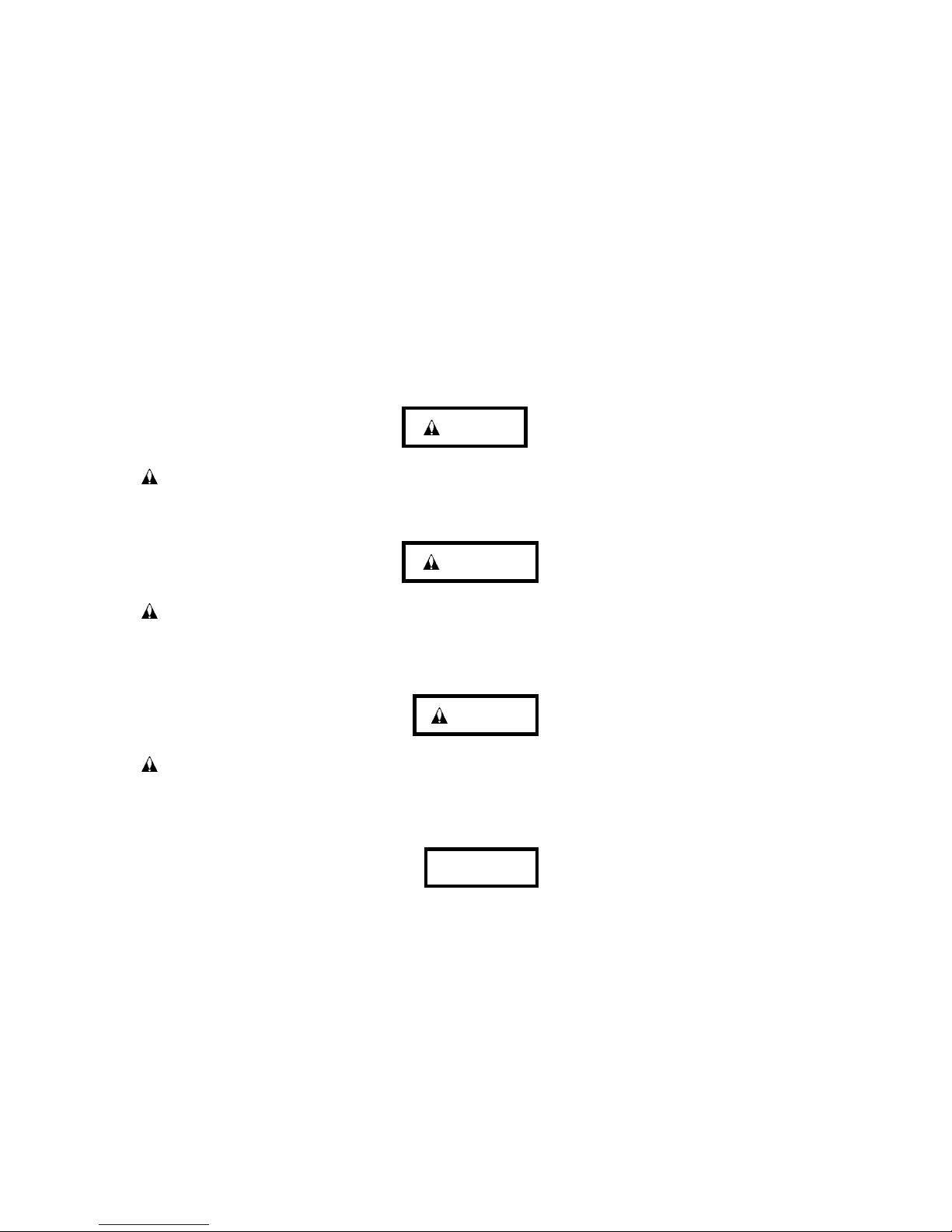
An outer view of the IDD is given in Figures 1.1 to 1.4. The IDD is composed of the disk, head,
spindle motor, hermetically sealed disk enclosure (DE) with actuator and air circulation filter, as
well as read/write pre-amp with the print card unit (PCA) of the controller.
Figure 1.1 MAH series MC outer view
C141-E103-02EN 1 - 5
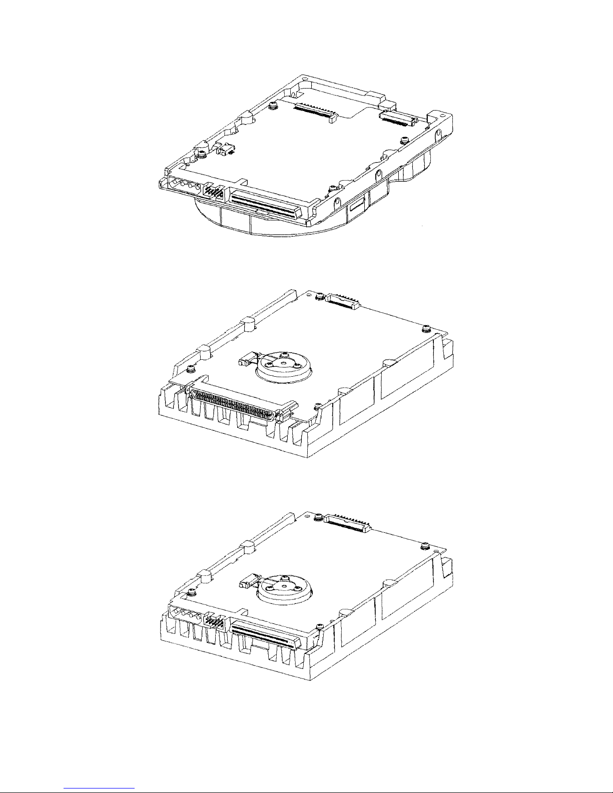
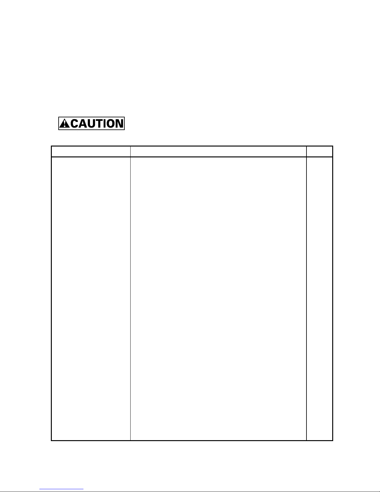
Figure 1.2 MAH series MP outer view
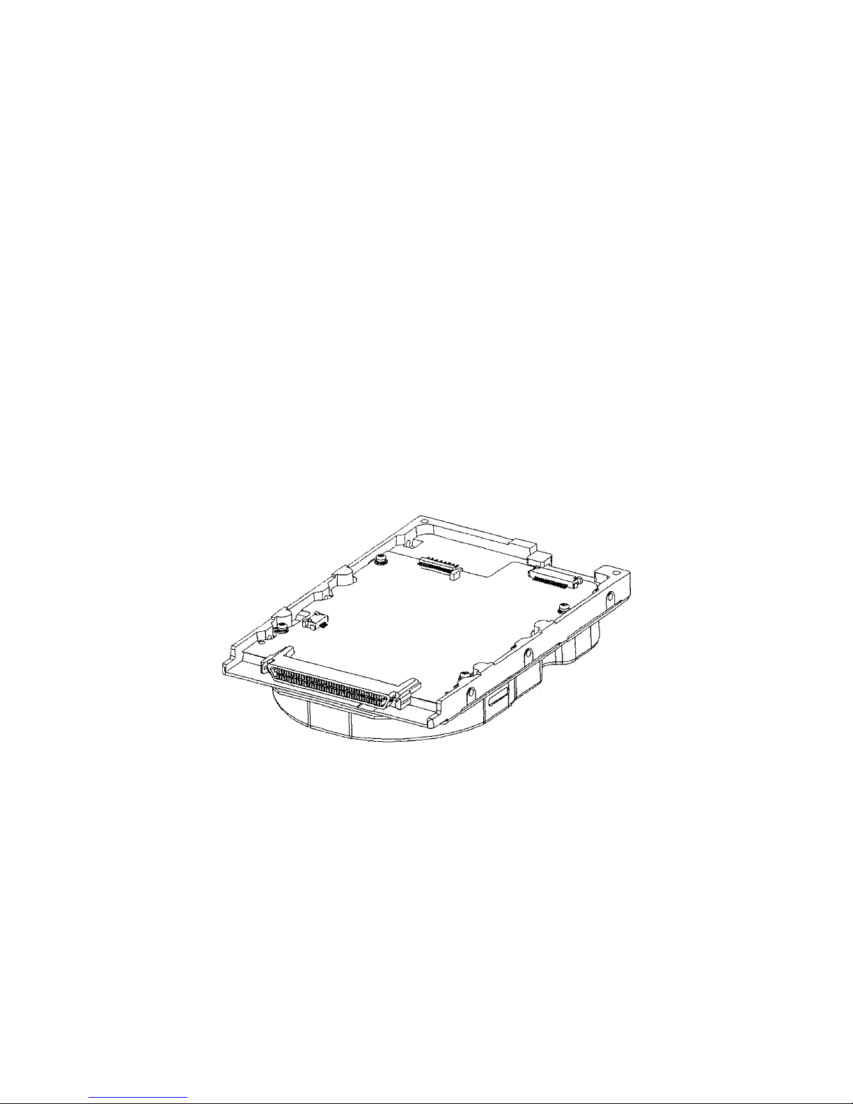
Figure 1.3 MAJ series MC outer view
Figure 1.4 MAJ series MP outer view
C141-E103-02EN1 - 6
(1) Disks
The disks have an outer diameter of 95 mm (3.74 inch) and inner diameter of 25 mm (0.98 inch)
for MAH series, and 84 mm (3.3 inch) outer diameter and 25 mm (0.98 inch) inner diameter for
MAJ series. The disks are good for at least 20,000 contact starts and stops. Each model contains
following number of disks.
MAH3182: 2
MAH3091: 1
MAJ3364: 5
MAJ3182: 3
MAJ3091: 2
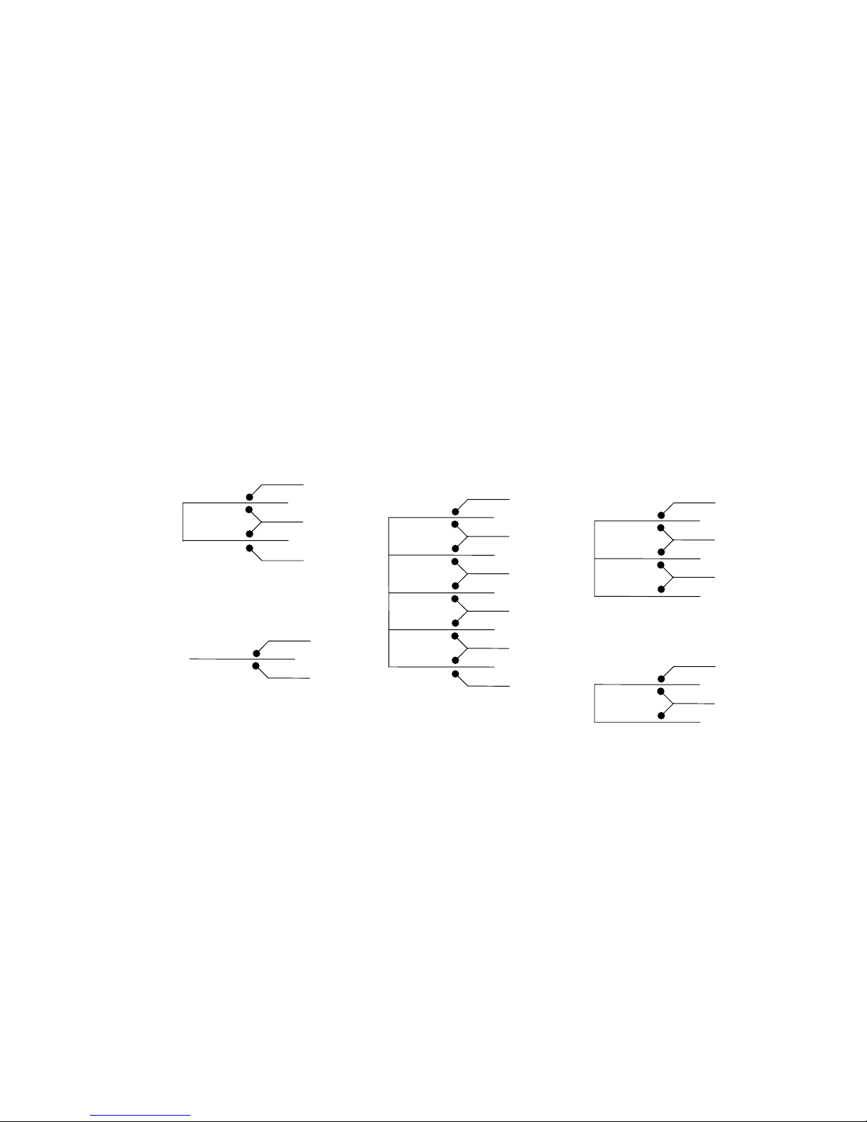
(2) Heads
The MR (Magnet - Resistive) of the CSS (contact start/stop) type heads are in contact with the
disks when the disks are not rotating, and automatically float when the rotation is started. Figure
1.5 shows the configuration of disks and heads
MAH3182
0
1
2
3
MAH3091
0
1
(3) Spindle motor
The disks are rotated by a direct-drive hall-less DC motor. The motor speed is controlled by a
feedback circuit using the counter electromotive current to precisely maintain the speed at ±0.5%
of the specified speed.
0
1
2
3
4
5
6
7
8
9
Figure 1.5 Disk/head configuration
MAJ3182MAJ3364
0
1
2
3
4
MAJ3091
0
1
2
(4) Actuator
The actuator, which uses a rotary voice coil motor (VCM), consumes little power and generates
little heat. The head assembly at the end of the actuator arm is controlled and positioned via
feedback of servo information in the data.
C141-E103-02EN 1 - 7

The actuator positions heads on the CCS zone over the disk and is locked by the mechanical lock
when the power is off or the spindle motor is stopped.
(5) Air circulation (recirculation filter, breather filter)
The heads, disks, and actuator are hermetically sealed inside a disk enclosure (DE) to keep out dust
and other pollutants. The DE has a closed-loop air recirculation system. Using the movement of
the rotating disks, air is continuously cycled through a filter. This filter will trap any dust
generated inside the enclosure and keep the air inside the DE contaminant free. To prevent
negative pressure in the vicinity of the spindle when the disks begin rotating, a breather filter is
attached. The breather filter also equalizes the internal air pressure with the atmospheric pressure
due to surrounding temperature changes.
(6) Read/write circuit
The read/write circuit utilizes a read channel mounted with a head IC that supports high-speed
transmission and an MEEPR4ML (Modified Enhanced Extended Partial Response Class 4
Maximum Likelihood) modulation/demodulation circuit in order to prevent errors being triggered
by external noise and to improve data reliability.
(7) Controller circuit
The controller circuit uses LSIs to increase the reliability and uses a high speed microprocessing
unit (MPU) to increase the performance of the SCSI controller.
C141-E103-02EN1 - 8
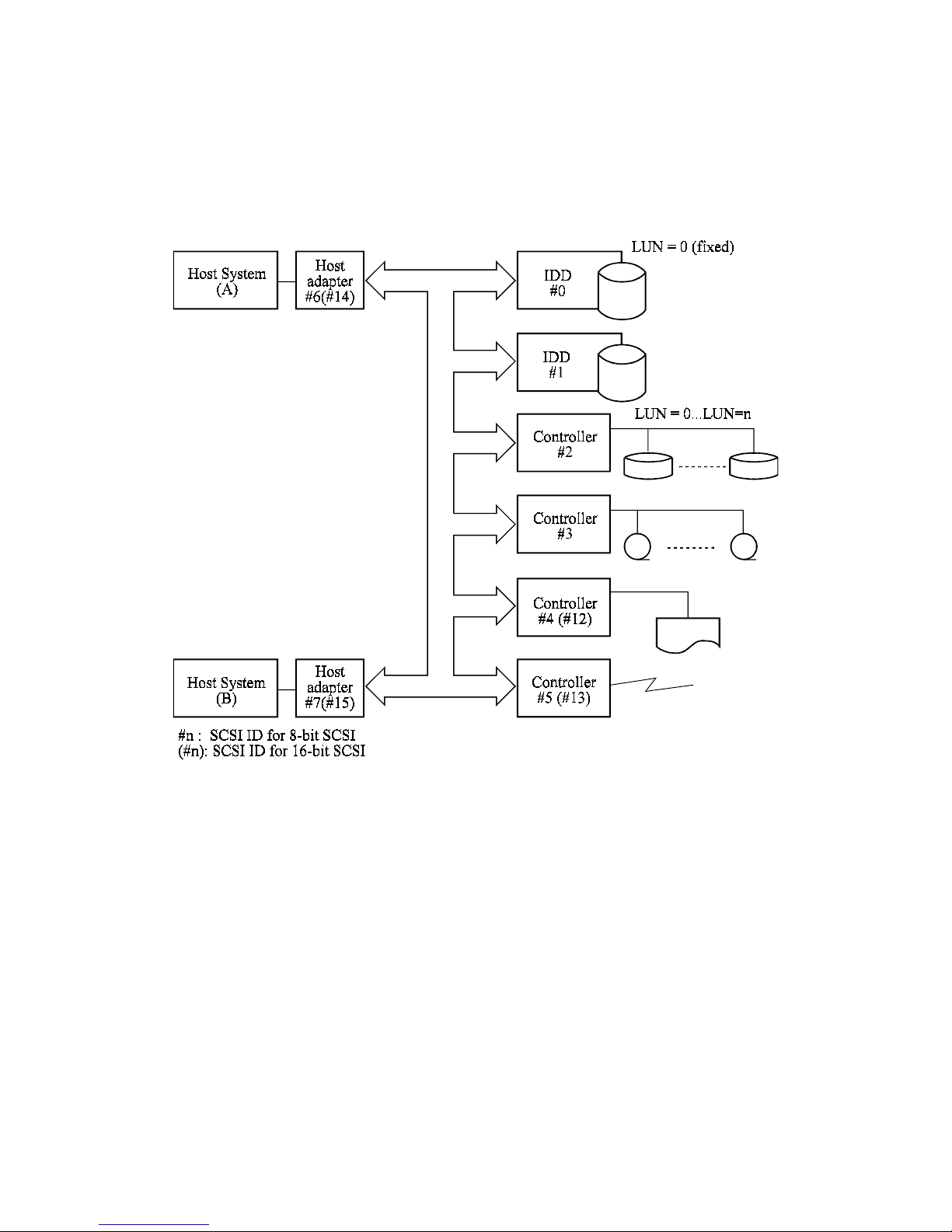
1.3 System Configuration
Figure 1.6 shows the system configuration. The IDDs are connected to the SCSI bus of host
systems and are always operated as target. The IDDs perform input/output operation as specified
by SCSI devices which operate as initiator.
SCSI bus
(1) SCSI bus configuration
Up to eight SCSI devices operating as an initiator or a target can be connected to the SCSI bus for
the 8-bit SCSI and up to 16 SCSI devices operating as an initiator or a target can be connected to
the SCSI bus for the 16-bit SCSI in any combination.
For example, the system can be configured as multi-host system on which multiple host computers
that operate as initiator or connected through the SCSI bus.
Using disconnect/reconnect function, concurrent input/output processing is possible on multi-SCSI
devices.
Figure 1.6 System configuration
C141-E103-02EN 1 - 9

(2) Addressing of peripheral device
Each SCSI device on the bus has its own unique address (SCSI ID:#n in Figure 1.6). For
input/output operation, a peripheral device attached to the SCSI bus that operates as target is
addressed in unit called as logical unit. A unique address (LUN: logical unit number) is assigned
for each logical unit.
The initiator selects one SCSI device by specifying that SCSI ID, then specifies the LUN to select
the peripheral device for input/output operation.
The IDD is constructed so that the whole volume of disk drive is a single logical unit, the
selectable number of SCSI ID and LUN are as follows:
• SCSI ID: 8-bit SCSI:Selectable from 0 to 7 (switch selectable)
16-bit SCSI:Selectable from 0 to 15 (switch selectable)
• LUN: 0 (fixed)
C141-E103-02EN1 - 10

CHAPTER 2 SPECIFICATIONS
2.1 Hardware Specifications
2.2 SCSI Function Specifications
This chapter describes specifications of the IDD and the functional specifications of the SCSI.
2.1 Hardware Specifications
2.1.1 Model name and part number
Each model has a different data format and front panel type when shipped. (See Appendix D for
the model name (type) and product number.)
The data format can be changed by reinitializing with the user's system.
C141-E103-02EN
2 - 1
 Loading...