

Page 1

GP 7000F
M200, M200R, M400A, M400R, M600, M600R
EditionDecember 1999
Page 2

CopyrightandTrademarks
Copyright©FujitsuSiemensComputersGmbH1999.
Allrightsreserved.
Deliverysubjecttoavailability;rightoftechnicalmodificationsreserved.
Allhardwareandsoftwarenamesusedaretrademarksoftheirrespectivemanufacturers.
Page 3

1 Preface
ThismanualcontainstheoperatinginstructionsfortheGranPower7000(GP7000F)system
from Fujitsu Siemens Computers. A chapter about the connection of Siemens specific devices precedes the actual operating instructions.
U42335-J-Z775-1-76 1
Page 4

Page 5
2 Console connections to GP 7000F
This chapter describes connections to the M200, M200R, M400A, M400R, M600 and
M600R models of the Fujitsu Siemens Computers GP 7000F system with a view to
attachingexistingcomponentsofSiemensdevicestoFujitsuequipment.Graphical or serial
consoles can be connected.
The GP 7000F systems do not support SIDATA
!
(installation by customer is not allowed).
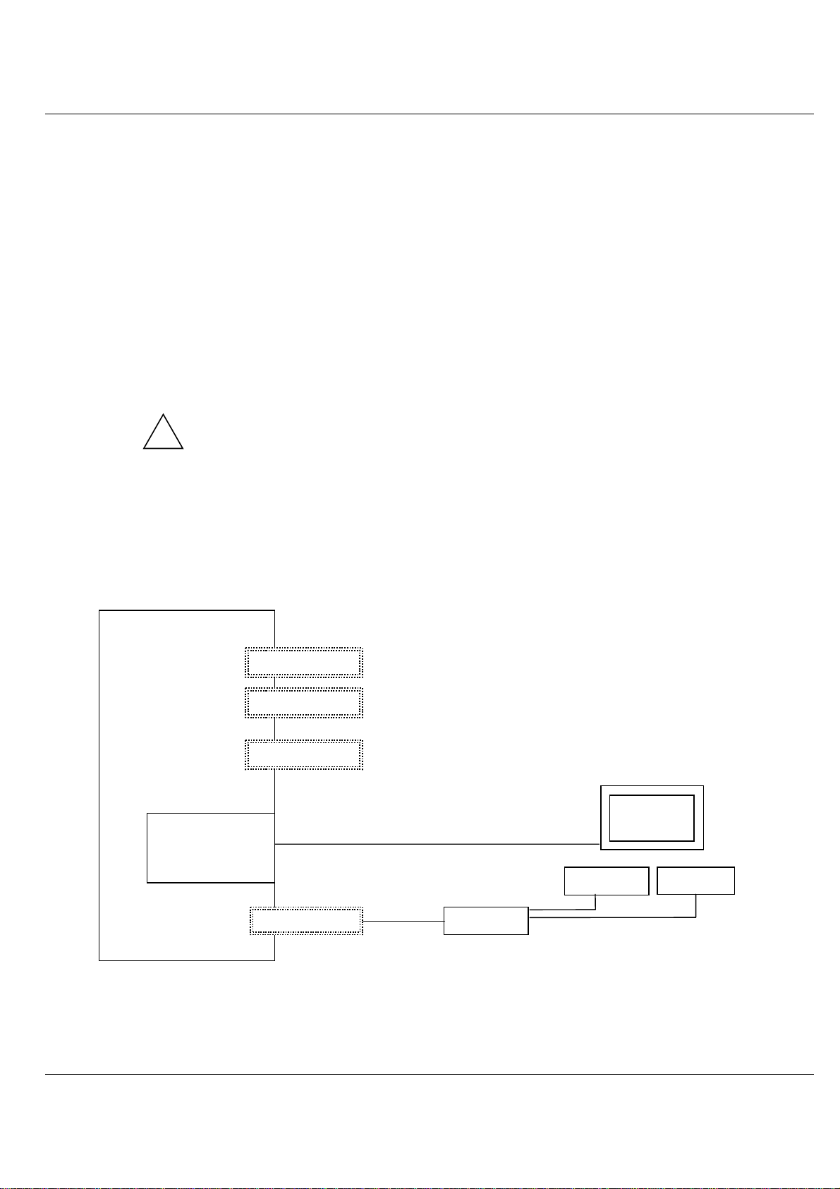
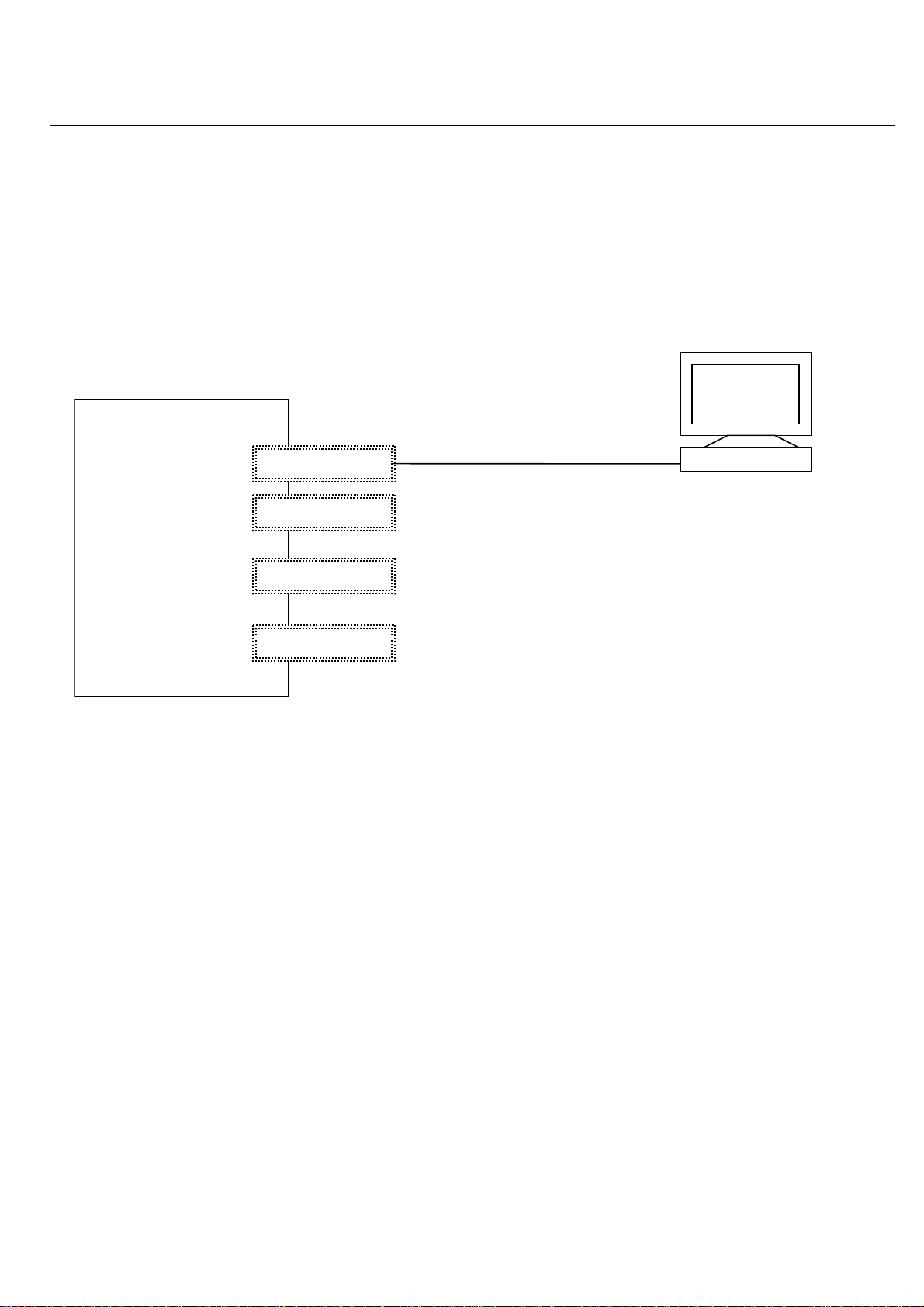
2.1 Graphical console
It is preferable to connect graphical consoles.
GP 7000F
system
PCI graphics
controller
D:GP70F-CC10
(option)
V.24 (A)
V.24 (B)
10/100 Mbit Eth
Keyboard/mouse
Teleservice
preferably
SUNAdapt
Monitor
Keyboard Mouse
(Keyboard with trackball
in the 19" rack)
U42335-J-Z775-1-76 3
Page 6
Graphical console Console connections to GP 7000F
The following technical requirements must be met in order to connect graphical consoles:
– PCI graphics controller D:GP70F-CC10
The GP 7000F models can be made into a workstation or server with a graphical
console by means of a PCI graphics card featuring a frame buffer.
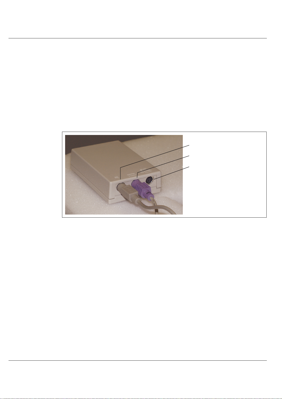
– An RM keyboard and mouse can be connected via the D:GP70F-AN10 interface
converter. All models in the GP 7000F server family have a Sun-compatible
keyboard/mouse interface. The adapter converts the interface signals to allow the
keyboard and 3-button mouse featuringa PC-compatible interfaceto be connected
to the server.
PS /2 M aus
PS/2 mouse
PS /2 Tastatur
PS/2 keyboard
SUN-
Sun keyboard/
Tastatur/M aus-
mouse interface
Schnittstelle
Keyboard/mouse adapter
– Monitor (CRT or LCD)
– Keyboard
–Mouse
The same monitor, keyboard and mouse types have been released as for the Siemens
systems.
4 U42335-J-Z775-1-76
Page 7
Console connections to GP 7000F Serial console
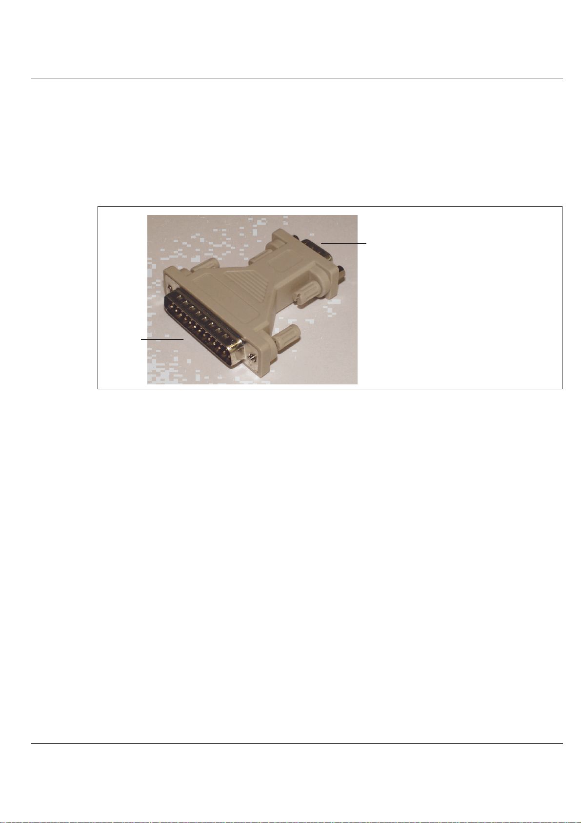
2.2 Serial console
A converter is used here to convert the 25-pin connector of the GP 7000F system to the
usual 9-pin V.24/COM connector. This converter is preinstalled at the factory. A VT100 or
VT200 emulation must be available for a serial console to be used.
V.24/C O M
9-pin
9polig
Dsub
25-pin
25polig
25/9-pin converter
U42335-J-Z775-1-76 5
Page 8
Serial console Console connections to GP 7000F
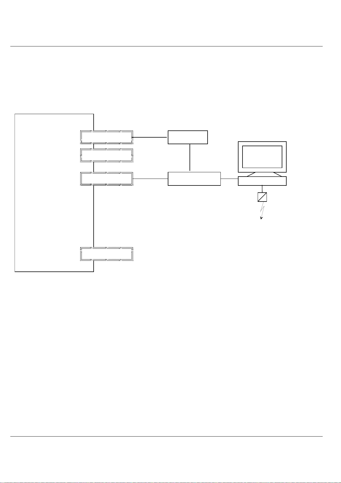
2.2.1 LAN console
ASolaris PC is connectedasa LAN console via anRCA (Remote CommunicationAdapter)
attached to the V.24 console interface. Up to six servers can be attached to one RCA.
GP 7000F
system
V.24 (A)
V.24 (B)
10/100 Mbit Eth
Keyboard/mouse
RCA
LAN
console
Ethernet hub
Teleservice
6 U42335-J-Z775-1-76
Page 9
Console connections to GP 7000F Serial console
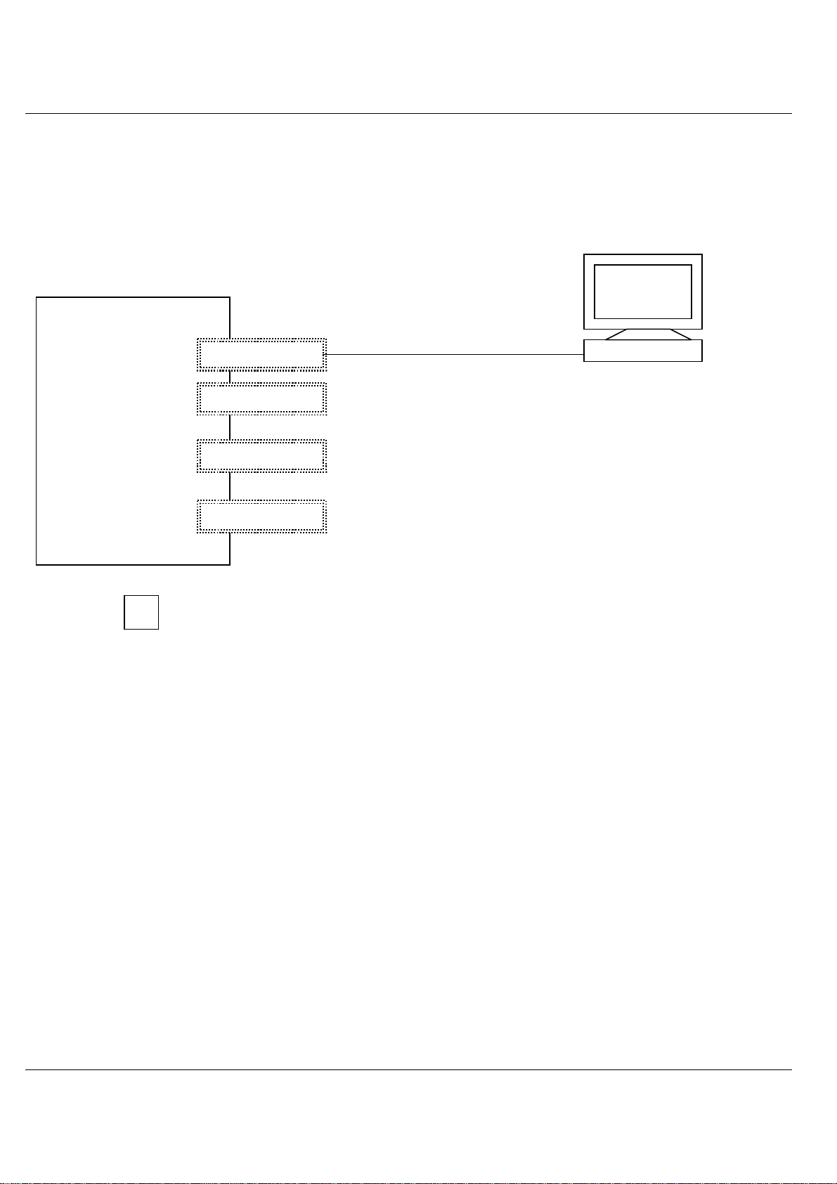
2.2.2 Standard PC with terminal emulation
a) Windows 98 or NT (with NetTerm, for instance, but not with HyperTerminal)
b) LINUX (with Minicom or Seyon)
c) Solaris (cu)
PC
(NT, Windows)
GP 7000F
system
V.24 (A)
V.24 (B)
10/100 Mbit Eth
Keyboard/mouse
Teleservice
preferably
U42335-J-Z775-1-76 7
Page 10
Teleservice Console connections to GP 7000F
2.2.3 TC20 or T100
Use of these terminals is intended as a migration solution only.
αααα
console
GP 7000F
system
V.24 (A)
V.24 (B)
10/100 Mbit Eth
Keyboard/mouse
Whenoperatingwith the LAN console,TC20or T100 it is not possibletoaccess the
i
Open Boot PROM using the BREAK signal.
2.3 Teleservice
The teleservice modem has to be connected via V.24 to the system board. The modemhas
to be ordered separately owing to national variants.
If a LAN console is used, connection of the modem is to the LAN console PC. Thus one
teleservice port serves all connected servers.
Teleservice
preferably
8 U42335-J-Z775-1-76
Page 11

P321-E102-02EN
USER'S MANUAL
Page 12

Page 13

FOR SAFE OPERATION
Handling of This Manual
This manual contains important information regarding the use and handling of this product. Read this manual
thoroughly. Pay special attention to the section "Important Warnings". Use the product according to the
instructions and information available in this manual.
FUJITSU makes every effort to prevent users and bystanders from being injured or from suffering from damages
to their property. Use the product according to this manual.
IMPORTANT READING
IMPORTANT NOTE TO USERS
READ CAREFULLY ALL THROUGHOUT THIS MANUAL BEFORE USING THE PRODUCT. INCORRECT
USE OF THE PRODUCT MAY CAUSE UNEXPECTED DAMAGE TO THE USERS OR BYSTANDERS.
While all efforts have been made to ensure the accuracy of all information in this manual, FUJITSU assumes no
liability to any party for any damage caused by errors or omissions or by statement of any kind in this manual, its
updates or supplements, whether such errors are omissions or statements resulting from negligence, accidents, or
any other cause. FUJITSU further assumes no liability for incidental or consequential damages arising from the
use of this manual. FUJITSU disclaims all warranties regarding the information contained herein, whether
expressed, implied, or statutory.
DO NOT MAKE MECHANICAL OR ELECTRICAL MODIFICATIONS TO THE EQUIPMENT. FUJITSU
LIMITED IS NOT RESPONSIBLE FOR REGULATORY COMPLIANCE OR SAFETY OF A MODIFIED
FUJITSU PRODUCT.
DO NOT REPAIR OR INSTALLTHE EQUIPMENT BY USERS. IT SHOULD BE PERFORMED BY A
TRAINED SERVICE ENGINNER.
i
Page 14
THIS PRODUCT IS NOT DESIGNED FOR USE IN ON-LINE CONTROL EQUIPMENT IN HAZARDOUS
ENVIRONMENTS SUCH AS OPERATION OF NUCLEAR FACILITIES, AIRCRAFT NAVIGATION OR
CONTROL, OR DIRECT LIFE SUPPORT MACHINES. HENCE, IF THESE PRODUCTS ARE USED IN
SUCH HAZARDOUS ENVIRONMENTS, FUJITSU LIMITED AND SUN MICROSYSTEMS, INC. DOES
NOT WARRANT THEM AT ALL.
FUJITSU reserves all the right to make changes to any products herein to improve reliability, function, or design,
without further notice and without obligation.
FCC Class A Notice
This equipment has been tested and found to comply with the limits for a Class A digital device,
pursuant to Part 15 of the FCC Rules. These limits are designed to provide reasonable protection
against harmful interference when the equipment is operated in a commercial environment. This
equipment generates, uses, and can radiate radio frequency energy and, if not installed and used in
accordance with the instruction manual, may cause harmful interference to radio communications.
Operation of this equipment in a residential area is likely to cause harmful interference in which
case the user will be required to correct the interference at his own expense.
DOC Class A Notice
This class A digital apparatus meets all requirements of the Canadian Interference-Causing
Equipment Regulations.
Cet appareil numerique de la class A respecte toutes les exigences du Reglement sur le material
brouiller du Canada.
Warning This is a Class A product of Electromagnetic Interference (EMI) standard. In a domestic
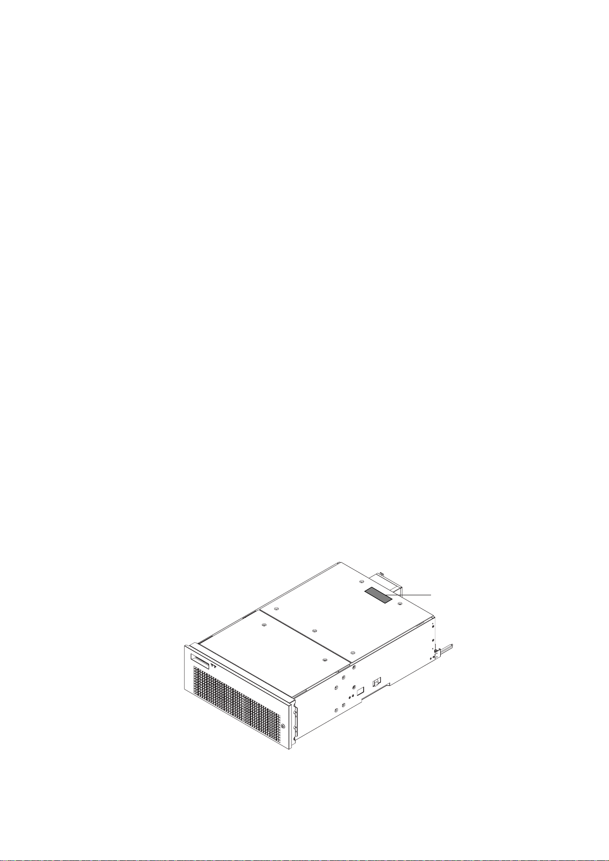
VCCI/FCC label
The VCCI/FCC labels for models 200R, 400R, and the Expansion file unit (GP7B7FLxx) are affixed in the
following locations:
environment this product may cause radio interference in which case the user may be required to
take adequate measures.
VCCI / FCC label
ii
Page 15
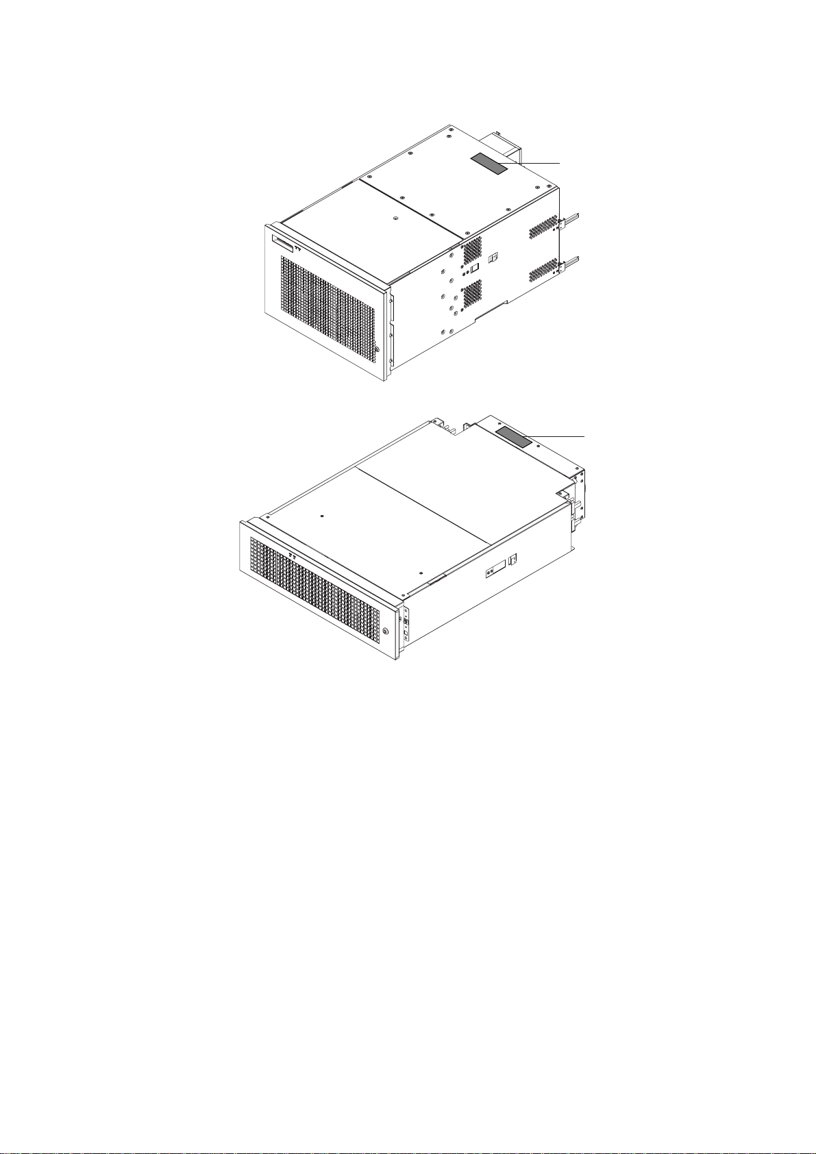
VCCI / FCC label
VCCI / FCC label
Laser Radiation Statement (EU)
Class 1 Laser Product
TRADEMARK ACKNOWLEDGMENTS
All rights reserved. This product and related documentation are protected by copyright and distributed under
licenses restricting its use, copying, distribution, and recompilation. No part of this product or related
documentation may be reproduced in any form by any means without prior written authorization of Fujitsu
Limited and its licensors, if any.
RESTRICTED RIGHTS LEGEND: Use, duplication, or disclosure by the United States Government is subject to
the restrictions set forth in DFARS 252.227-7013 (c) (1) (ii) and FAR 52.227-19.
The product described in this book may be protected by one or more U.S. patents, foreign patents, or pending
applications.
iii
Page 16

TRADEMARKS
Fujitsu and the Fujitsu logo are trademarks of Fujitsu Limited.
SPARC64 is a registered trademark or trademark of SPARC International, Inc. in the United States
and other countries used under license by Fujitsu Ltd. Products bearing SPARC64 trademarks
comply with SPARC V9 architecture developed by SPARC International, Inc. Products bearing the
SPARC trademarks are based on an architecture originally developed by Sun Microsystems, Inc. "
Sun, the Sun logo, Sun Microsystems, Sun Microsystems Computer Corporation, the Sun
Microsystems Computer Corporation logo, SunSoft, the SunSoft logo, Solaris, Solaris PEX, SunOS,
SunLink, OpenWindows, Direct Xlib, SunSHIELD, NeWS, NeWSprint, SunInstall, DeskSet, ONC,
ONC+, OpenBoot, Online DiskSuite, NFS, JumpStart, AnswerBook, the AnswerBook logo,
SunDiag, ToolTalk, Sun PC, and Wabi are trademarks or registered trademarks of Sun
Microsystems, Inc., in the U.S. and certain other countries.
UNIX is a registered trademark in the United States and other countries, licensed exclusively
through X/Open Company Ltd.
All other product names mentioned herein are the trademarks of their respective owners.
THIS PUBLICATION IS PROVIDED "AS IS" WITHOUT WARRANTY OF ANY KIND, EITHER EXPRESS
OR IMPLIED, INCLUDING, BUT NOT LIMITED TO, THE IMPLIED WARRANTIES OR
MERCHANTABILITY, FITNESS FOR A PARTICULAR POURPOSE, OR NONINFRINGEMENT.
THIS PUBLICATION COULD INCLUDE TECHNICAL INACCURACIES OR TYPOGRAPHICAL ERRORS.
CHANGES ARE PERIODICALLY ADDED TO THE INFORMATION HEREIN; THESE CHANGES WILL BE
INCORPORATED IN NEW EDITIONS OF THE PUBLICATION. FUJITSU LIMITED MAY MAKE
IMPROVEMENTS AND/OR CHANGES IN THE PRODUCT(S) AND/OR THE PROGRAM(S) DESCRIBED
IN THIS PUBLICATION AT ANY TIME.
Documents produced by FUJITSU may contain technology controlled under the
Foreign Exchange and Foreign Trade Control Law of Japan. The document
which contains such technology should not be exported from Japan or
transferred to anyone other than residents of Japan without first obtaining
license from the Ministry of International Trade and Industry of Japan in
accordance with the above law.
Second Edition: November 1999
This manual may be best printed on A4 size. If it is printed on 8.5" ( 11" size, adjust your printer setting in advance.
The contents of this manual may be revised without prior notice.
The contents of this manual shall not be disclosed in any way or reproduced in any media without the express
written permission of Fujitsu Limited.
All Rights Reserved, Copyright (c) FUJITSU LIMITED 1999
iv
Page 17

This manual explains the function, configuration, and operation of GP7000F. This manual is intended for the
experienced users who have a basic knowledge of computer systems.
The structure of this manual is as follows:
Introduction to Chapters
CHAPTER 1 Product Outline
Chapter 1 describes the distinctive features of GP7000F.
CHAPTER 2 M200 Main Cabinet
Chapter 2 explains the device configuration and operation of M200 Main Cabinet.
CHAPTER 3 M200R Main Cabinet
Chapter 3 explains the device configuration and operation of M200R Main Cabinet.
CHAPTER 4 M400A Main Cabinet
Chapter 4 explains the device configuration and operation of M400A Main Cabinet.
CHAPTER 5 M400R Main Cabinet
Chapter 5 explains the device configuration and operation of M400R Main Cabinet.
CHAPTER 6 M600 Main Cabinet
Chapter 6 explains the device configuration and operation of M600 Main Cabinet.
CHAPTER 7 M600R Main Cabinet
Chapter 7 explains the device configuration and operation of M600R Main Cabinet.
CHAPTER 8 Expansion Disk Cabinet
Chapter 8 describes the distinctive features of the GP7000F external disk cabinet.
CHAPTER 9 Expansion File Unit Type-2(GP7B7FLxx)
Chapter 9 describes the distinctive features of the GP7000F rack mount expansion disk unit.
CHAPTER 10 Expansion File Unit(GP7B7FU1xx)
Chapter 10 describes the distinctive features of the GP7000F rack mount expansion disk unit.
CHAPTER 11 Input-Output Units
Chapter 11 explains the specifications of Input-Output units.
Preface
v
Page 18
CHAPTER 12 External Interface
Chapter 12 explains the external interface of the main cabinet such as UPS Control Interface,
RS232C Interface, and Centronics Interface.
CHAPTER 13 RCI Setting
Chapter 13 explains the description of RCI commands to be used for managing nodes.
CHAPTER 14 Troubleshooting
Chapter 14 will help the user isolate the cause of system failures, and provides suggested solutions.
Conventions for Warning Messages
A warning message consists of a signal and statements. The signal consists of a symbol and a signal word or just a
signal word.
The following are the signals and their meanings:
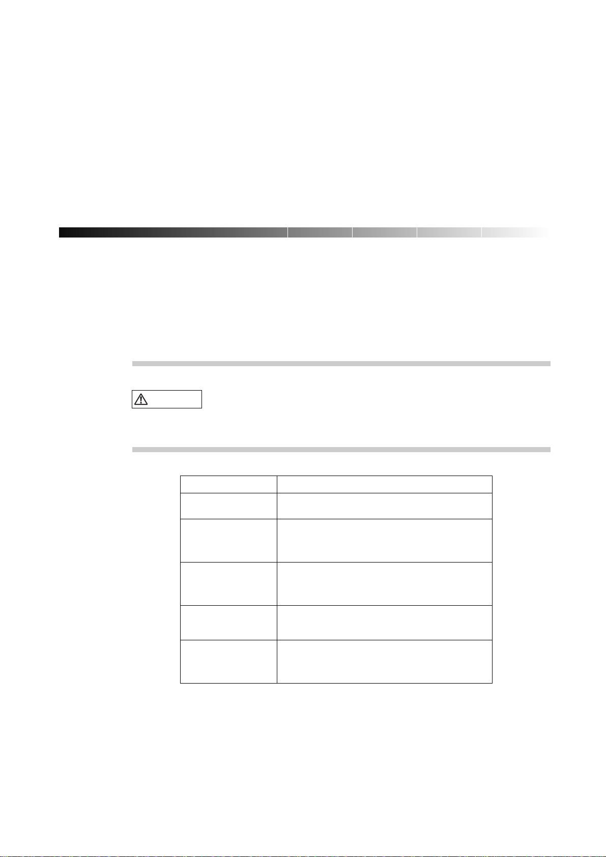
CAUTION
This indicates a hazardous situation could result in minor or moderate personal injury if the user
does not perform the procedure correctly. This signal also indicates that damage to the product or
other property,may occur if the user does not perform the procedure correctly.
Attention
IMPORTANT
This indicates information that could help the user use the product more efficiently.
In the text, the signal is centered, followed below by the indented message. A wider line space precedes and
follows the message to show where the message begins and ends. The following is an example:
(Example)
CAUTION
Please forward any comments you may have regarding this manual.
Tomake this manual easier for users to understand, opinions from readers are needed. Please write your opinions
or requests on the "Comment Form" sheet at the back of this manual and forward it to the address provided on the
sheet.
Data destruction: Do not press these buttons before installing the necessary
software package. Otherwise, data may be destroyed. Turn off the system in the
OBP prompt state if the software package is not installed.
vi
Page 19

vii
Page 20
Important Warnings
The following are cautions found in this manual. They have been compiled here with corresponding page
references.
CAUTION
Task Warning
Normal Operation Data destruction: Pressing the RESET switch while the
system is running may destroy data.
System Installation Be sure to install software packages from "Basic Software
Extension" or "Enhanced Support Facility. Otherwise, above
switch functions or proper messages on LCD panel are not
guaranteed.
Terminal break command If used improper commands at the ok prompt, the GP7000F
may be destroyed. If you need to used any other commands
except shown on this manual, you should well understand
the function and usage of the command before using it.
Power Off Be sure to eject backup tape media and any diskettes before
power-off the system, if the media are installed. Other
wise, the data on the media may be destroyed.
Normal Operation Except in an emergency, never turn off the AC switch or
disconnect the power cable wile the GP7000F main cabinet is
turned on. If you do, data in the disk drive may be
destroyed.
A hazardous situation could result in minor or moderate personal injury if the
user does not perform the procedure correctly. Also, damage to the product or
other property may occur.
viii
Page 21

Task Warning
System Installation Install "Basic Software Extension" or "Enhanced Support
Facility"before operating the system. Without this package,
incorrect front panel operations and hardware errors may cause
the system to shutdown or destroy data.
Disk Expansion Unit Be sure to replace the power supply fan when installing the
Installation Disk Expansion Unit. Otherwise, the system will shutdown or
disk units will deteriorate due to a temperature rise in the
M200 main cabinet caused by insufficient cooling.
Disk Expansion Unit If the installing location (slot) is not set or set
Installation incorrectly, the disk drive may not be hot-swappable.
Data may be destroyed as a result of inadvertently replacing
the different disk drive. Be sure to set the installing
location (slot) correctly.
Also, while replacing or initializing NVRAM, set the
installing location again.
Normal Operation Do not set the AC main line switch to OFF, not disconnect
the power cable or RCI cable while the GP7000F main cabinet
is powered on, unless absolutely necessary. Otherwise, the
data may be destroyed in the disk units.
Normal Operation Do not set the AC main line switch to OFF, nor disconnect
the power cable or RCI cable while the GP7000F main cabinet
is powered on, unless absolutely necessary. Otherwise, the
data in the disk units may be destroyed.
Replacing Disk Drives When replacing the disk unit,take the following precautions.
If these precautions are not observed, the disk unit or its
data may be destroyed.
Formatting Disk Drives Carefully proceed formatting a disk drive. Once formatting
a disk drive, data on the disk never restored, if you don't
have backup files.
Handling Floppy Disks Do not eject a floppy disk while the access LED is on, other
wise the floppy disk or the data on the diskette may be
destroyed.
For information on the handling method, see Table 11.2,
"Handling floppy disks."
Ejecting DAT cartridge Data destruction: Do not press the eject switch during an
operation (when the tape LED is blinking). If the eject
switch is held down for about 5 seconds or pressed 3 times
within a 5 minutes period, the forced ejection function may
execute and the data being written may be destroyed.
Handling DAT cartridge When using the data cartridge (DAT), take the following
precautions. If these precautions are not observed, the
DAT unit or its data may be destroyed.
Storing 8-mm cartridge When using or storing the data cartridge, take the following
precautions. If these precautions are not taken, the data
on 8-mm tape may be destroyed.
Ejecting QIC cartridge Data destruction: Do not press the eject switch during an
operation. The forced ejection function may operate and
data being written may be destroyed.
Storing QIC cartridge When using or storing the data cartridge, take the following
precautions. If these precautions are not taken, the QIC
tape unit or its data may be destroyed.
ix
Page 22

Page 23
CONTENTS
CHAPTER 1 Product Outline 1
1.1 Key Features
1.2 Operator Panel
1.3 External Interface
1.4 Console
1.5 Power On/Off
1.6 Installation of Basic Software Extension or Enhanced Support Facility
1.7 local-mac-address Property
:::::::::::::::::::::::::::::::::::::
::::::::::::::::::::::::::::::::::::
::::::::::::::::::::::::::::::::::
:::::::::::::::::::::::::::::::::::::::
::::::::::::::::::::::::::::::::::::
::::::::
::::::::::::::::::::::::::::::
10
11
12
12
CHAPTER 2 M200 Main Cabinet 13
2.1 Overview
2.2 Device Configuration
2.3 Systemboard
2.4 Disk Units
::::::::::::::::::::::::::::::::::::::
:::::::::::::::::::::::::::::::::
:::::::::::::::::::::::::::::::::::::
::::::::::::::::::::::::::::::::::::::
14
15
19
21
2
5
8
2.5 PCI Slots
2.6 Installation
:::::::::::::::::::::::::::::::::::::::
::::::::::::::::::::::::::::::::::::::
23
23
i
Page 24
CHAPTER 3 M200R Main Cabinet 27
3.1 Overview
3.2 Device Configuration
3.3 Systemboard
3.4 Disk Units
3.5 PCI Slots
3.6 Installation
::::::::::::::::::::::::::::::::::::::
:::::::::::::::::::::::::::::::::
:::::::::::::::::::::::::::::::::::::
::::::::::::::::::::::::::::::::::::::
:::::::::::::::::::::::::::::::::::::::
::::::::::::::::::::::::::::::::::::::
28
29
32
34
35
36
CHAPTER 4 M400A Main Cabinet 41
4.1 Overview
4.2 Device Configuration
4.3 Systemboard
4.4 Disk Units
4.5 PCI Slots
::::::::::::::::::::::::::::::::::::::
:::::::::::::::::::::::::::::::::
:::::::::::::::::::::::::::::::::::::
::::::::::::::::::::::::::::::::::::::
:::::::::::::::::::::::::::::::::::::::
42
43
46
48
49
4.6 Installation
::::::::::::::::::::::::::::::::::::::
50
CHAPTER 5 M400R Main Cabinet 53
5.1 Overview
5.2 Device Configuration
5.3 Systemboard
5.4 Disk Units
5.5 PCI Slots
5.6 Installation
::::::::::::::::::::::::::::::::::::::
:::::::::::::::::::::::::::::::::
:::::::::::::::::::::::::::::::::::::
::::::::::::::::::::::::::::::::::::::
:::::::::::::::::::::::::::::::::::::::
::::::::::::::::::::::::::::::::::::::
54
55
58
60
61
62
CHAPTER 6 M600 Main Cabinet 67
6.1 Overview
::::::::::::::::::::::::::::::::::::::
68
6.2 Device Configuration
:::::::::::::::::::::::::::::::::
69
ii
Page 25
CONTENTS
6.3 Systemboard
6.4 Disk Units
6.5 PCI Slots
6.6 Installation
:::::::::::::::::::::::::::::::::::::
::::::::::::::::::::::::::::::::::::::
:::::::::::::::::::::::::::::::::::::::
::::::::::::::::::::::::::::::::::::::
72
75
75
77
CHAPTER 7 M600R Main Cabinet 81
7.1 Overview
7.2 Device Configuration
7.3 Systemboard
7.4 Disk Units
7.5 PCI Slots
7.6 Installation
::::::::::::::::::::::::::::::::::::::
:::::::::::::::::::::::::::::::::
:::::::::::::::::::::::::::::::::::::
::::::::::::::::::::::::::::::::::::::
:::::::::::::::::::::::::::::::::::::::
::::::::::::::::::::::::::::::::::::::
82
83
86
88
89
91
CHAPTER 8 Expansion Disk Cabinet 95
8.1 Product Outline
8.2 Device Configuration
8.3 Hot System Replacement
8.4 Installation
:::::::::::::::::::::::::::::::::::
:::::::::::::::::::::::::::::::::
:::::::::::::::::::::::::::::::
::::::::::::::::::::::::::::::::::::::
96
97
101
102
CHAPTER 9 Expansion File Unit Type-2 (GP7B7FLxx) 105
9.1 Product Outline
9.2 Device Configuration
9.3 Hot System Replacement
9.4 Installation
:::::::::::::::::::::::::::::::::::
:::::::::::::::::::::::::::::::::
:::::::::::::::::::::::::::::::
::::::::::::::::::::::::::::::::::::::
106
107
109
110
CHAPTER 10 Expansion File Unit (GP7B7FU1xx) 113
10.1 Product Outline
:::::::::::::::::::::::::::::::::::
114
iii
Page 26
10.2 Device Configuration
:::::::::::::::::::::::::::::::::
115
10.3 Hot System Replacement
10.4 Installation
::::::::::::::::::::::::::::::::::::::
:::::::::::::::::::::::::::::::
117
118
CHAPTER 11 Input-Output Units 121
11.1 Disk Units
11.2 Floppy Disk Units
11.3 CD-ROM Unit
11.4 Tape Unit
11.5 DAT Unit
11.6 8-mm TapeUnit
11.7 QIC Tape Unit
::::::::::::::::::::::::::::::::::::::
::::::::::::::::::::::::::::::::::
::::::::::::::::::::::::::::::::::::
::::::::::::::::::::::::::::::::::::::
::::::::::::::::::::::::::::::::::::::
:::::::::::::::::::::::::::::::::::
::::::::::::::::::::::::::::::::::::
122
123
126
128
129
135
140
CHAPTER 12 External Interfaces 145
12.1 UPS Control Interface
12.2 RS232C Interface
12.3 Parallel Interface
::::::::::::::::::::::::::::::::
::::::::::::::::::::::::::::::::::
:::::::::::::::::::::::::::::::::::
146
148
151
CHAPTER 13 RCI Setting 153
13.1 Overview
13.2 RCI Commands
13.3 Liquid Crystal Display (LCD) Specifications
::::::::::::::::::::::::::::::::::::::
:::::::::::::::::::::::::::::::::::
:::::::::::::::::::::
154
154
155
CHAPTER 14 Troubleshooting 157
14.1 Overview
14.2 Commands at the ok prompt
::::::::::::::::::::::::::::::::::::::
:::::::::::::::::::::::::::::
158
158
iv
14.3 Initial Diagnosis Sequence
::::::::::::::::::::::::::::::
159
Page 27

CONTENTS
14.4 SCF Error Messages
:::::::::::::::::::::::::::::::::
160
v
Page 28

Page 29
ILLUSTRATIONS
Figure 1.1 Operator Panel (M200, M600)
::::::::::::::::::::::::::::::
Figure 1.2 Operator Panel (M200R, M400A, M400R, M600R)
Figure 2.1 Front View of M200 Main Cabinet
Figure 2.2 Open View of M200 Main Cabinet
Figure 2.3 Rear View of M200 Main Cabinet
Figure 2.4 Systemboard Layout of M200
Figure 2.5 Disk Drive Bays of M200 Main Cabinet
Figure 3.1 Front View of M200R Main Cabinet
Figure 3.2 Open View of M200R Main Cabinet
Figure 3.3 Rear View of M200R Main Cabinet
Figure 3.4 Systemboard Layout of M200R
Figure 4.1 Front View of M400A Main Cabinet
Figure 4.2 Open View of M400A Main Cabinet
Figure 4.3 Rear View of M400A Main Cabinet
Figure 4.4 Systemboard Layout of M400A
::::::::::::::::::::::::::::
::::::::::::::::::::::::::::
::::::::::::::::::::::::::::
::::::::::::::::::::::::::::::
:::::::::::::::::::::::::
:::::::::::::::::::::::::::
:::::::::::::::::::::::::::
:::::::::::::::::::::::::::
:::::::::::::::::::::::::::::
:::::::::::::::::::::::::::
:::::::::::::::::::::::::::
:::::::::::::::::::::::::::
:::::::::::::::::::::::::::::
:::::::::::::::::::
5
5
14
16
18
19
21
28
29
31
32
42
43
45
46
Figure 5.1 Front View of M400R Main Cabinet
Figure 5.2 Open View of M400R Main Cabinet
Figure 5.3 Rear View of M400R Main Cabinet
Figure 5.4 Systemboard Layout of M400R
:::::::::::::::::::::::::::::
Figure 6.1 Front View of M600 Main Cabinet
:::::::::::::::::::::::::::
:::::::::::::::::::::::::::
:::::::::::::::::::::::::::
::::::::::::::::::::::::::::
54
55
57
58
68
vii
Page 30
Figure 6.2 Open View of M600 Main Cabinet
::::::::::::::::::::::::::::
69
Figure 6.3 Rear View of M600 Main Cabinet
Figure 6.4 Systemboard Layout of M600
Figure 6.5 PCI IO Board Layout of M600
Figure 7.1 Front View of M600R Main Cabinet
Figure 7.2 Open View of M600R Main Cabinet
::::::::::::::::::::::::::::
::::::::::::::::::::::::::::::
::::::::::::::::::::::::::::::
:::::::::::::::::::::::::::
:::::::::::::::::::::::::::
Figure 7.3 Front View of M600R Main Cabinet (remove Front cover)
Figure 7.4 Rear View of M600R Main Cabinet
Figure 7.5 Systemboard Layout of M600R
Figure 7.6 PCIBPR Board Layout of M600R
Figure 7.7 PCIRSR Board Layout of M600R
Figure 8.1 Front View of Expansion Disk Cabinet
Figure 8.2 Drive Bays of Expansion Disk Cabinet
Figure 8.3 Rear View of Expansion Disk Cabinet
Figure 9.1 Front View of Expansion File Unit Type-2
Figure 9.2 Drive Bays of Expansion File Unit Type-2
Figure 9.3 Drive Bays of Expansion File Unit Type-2
:::::::::::::::::::::::::::
:::::::::::::::::::::::::::::
::::::::::::::::::::::::::::
::::::::::::::::::::::::::::
::::::::::::::::::::::::::
::::::::::::::::::::::::::
::::::::::::::::::::::::::
::::::::::::::::::::::::
::::::::::::::::::::::::
::::::::::::::::::::::::
::::::::::::::::
71
72
75
82
83
84
85
86
89
89
97
98
100
106
107
108
Figure 9.4 Rear View of Expansion File Unit Type-2
Figure 10.1 Front View of Expansion File Unit
Figure 10.2 Drive Bays of Expansion File Unit
Figure 10.3 Rear View of Expansion File Unit
Figure 11.1 Floppy Disk Unit Front Panel
Figure 11.2 Inserting Floppy Disks
::::::::::::::::::::::::::::::::::
Figure 11.3 CD-ROM Unit Front Panel
Figure 11.4 Mark on CD-ROM Disk
Figure 11.5 DAT Unit Front Panel
Figure 11.6 DDS Logos
:::::::::::::::::::::::::::::::::::::::
:::::::::::::::::::::::::::::::::
::::::::::::::::::::::::::::::::::
Figure 11.7 DDS Media Recognition System Logo
::::::::::::::::::::::::::::
::::::::::::::::::::::::::::
::::::::::::::::::::::::::::
::::::::::::::::::::::::::::::
::::::::::::::::::::::::::::::::
::::::::::::::::::::::::::
Figure 11.8 Inserting a Data Cartridge in The DAT Unit
Figure 11.9 DAT Data Cartridge Write-protection Tab
Figure 11.10 8-mm Tape Unit Front Panel
Figure 11.11 8-mm Tape Data Cartridge
:::::::::::::::::::::::::::::::
::::::::::::::::::::::::::::::::
Figure 11.12 Cleaning Cartridge of The 8-mm Tape Unit
::::::::::::::::::::::::
::::::::::::::::::::::::
::::::::::::::::::::::::
::::::::::::::::::::::::
108
114
115
116
123
124
126
127
130
132
132
132
133
136
137
139
viii
Figure 11.13 Cleaning Cartridge of The 8-mm Tape Unit
Figure 11.14 QIC Tape Drive Front Panel
Figure 11.15 QIC Data Cartridge
::::::::::::::::::::::::::::::::::::
:::::::::::::::::::::::::::::::
::::::::::::::::::::::::
139
140
142
Page 31

ILLUSTRATIONS
Figure 12.1 Signal Configuration
:::::::::::::::::::::::::::::::::::
Figure 12.2 Configuration of Signal Line when Connecting DCE Device(Example)
Figure 12.3 Configuration of Signal Line when Connecting DTE Line(Example)
Figure 14.1 Power-on Sequence
:::::::::::::::::::::::::::::::::::
::::::::::
:::::::::::
147
150
150
159
ix
Page 32

TABLES
Table1.1 Data Protection for Components and Interfaces
Table1.2 POWER LED
Table1.3 CHECK LED
Table1.4 MODE Switch Settings
Table1.5 Connectors and Switches
::::::::::::::::::::::::::::::::::::::
::::::::::::::::::::::::::::::::::::::
::::::::::::::::::::::::::::::::::
:::::::::::::::::::::::::::::::::
Table1.6 Connectors and Switches for Maintenance
Table2.1 Fans
Table2.2 PCI Slot Specifications
:::::::::::::::::::::::::::::::::::::::::::
::::::::::::::::::::::::::::::::::
::::::::::::::::::::::
::::::::::::::::::::::::
Table2.3 Installation Specifications of M200 Main Cabinet (1)
Table2.4 Installation Specifications of M200 Main Cabinet (2)
Table3.1 Fans
Table3.2 Power Supply Units
Table3.3 PCI Slot Specifications
Table3.4 Mounting Combination for Expansion Rack
Table3.5 Installation Specifications of M200R (1)
Table3.6 Installation Specifications of M200R (2)
:::::::::::::::::::::::::::::::::::::::::::
:::::::::::::::::::::::::::::::::::
::::::::::::::::::::::::::::::::::
:::::::::::::::::::::::
:::::::::::::::::::::::::
:::::::::::::::::::::::::
:::::::::::::::::::
:::::::::::::::::::
3
6
6
7
9
9
17
23
24
25
30
30
35
37
38
39
Table4.1 Fans
Table4.2 Power Supply Units
Table4.3 PCI Slot Specifications
Table4.4 Installation Specifications of M400A Main Cabinet (1)
Table4.5 Installation Specifications of M400A Main Cabinet (2)
:::::::::::::::::::::::::::::::::::::::::::
:::::::::::::::::::::::::::::::::::
::::::::::::::::::::::::::::::::::
::::::::::::::::::
::::::::::::::::::
44
44
49
51
52
x
Page 33

TABLES
Table5.1 Fans
Table5.2 Power Supply Units
Table5.3 PCI Slot Specifications
Table5.4 Mounting Combination for Expansion Rack
Table5.5 Installation Specifications of M400R
Table5.6 Installation Specifications of M400R (2)
Table6.1 Fans
Table6.2 Power Supply Units
Table6.3 CPU Module Configurations
Table6.4 PCI Slot Specifications
:::::::::::::::::::::::::::::::::::::::::::
:::::::::::::::::::::::::::::::::::
::::::::::::::::::::::::::::::::::
:::::::::::::::::::::::
:::::::::::::::::::::::::::
:::::::::::::::::::::::::
:::::::::::::::::::::::::::::::::::::::::::
:::::::::::::::::::::::::::::::::::
:::::::::::::::::::::::::::::::
::::::::::::::::::::::::::::::::::
Table6.5 Installation Specifications of M600 Main Cabinet (1)
Table6.6 Installation Specifications of M600 Main Cabinet (2)
Table7.1 Fans
Table7.2 Power Supply Units
Table7.3 CPU Module Configurations
Table7.4 PCI Slot Specifications
:::::::::::::::::::::::::::::::::::::::::::
:::::::::::::::::::::::::::::::::::
:::::::::::::::::::::::::::::::
::::::::::::::::::::::::::::::::::
:::::::::::::::::::
:::::::::::::::::::
56
56
61
63
64
65
70
71
73
76
78
79
84
85
87
90
Table7.5 Mounting Combination for Expansion Rack
Table7.6 Installation Specifications of M600R
Table7.7 Installation Specifications of M600R (2)
Table8.1 CHECK LED Status
Table8.2 LEDs
::::::::::::::::::::::::::::::::::::::::::
:::::::::::::::::::::::::::::::::::
:::::::::::::::::::::::
:::::::::::::::::::::::::::
:::::::::::::::::::::::::
Table8.3 Expansion Disk Cabinet Installation Specifications (1)
Table8.4 Installation Specifications of Expansion Disk Cabinet (2)
Table9.1 CHECK LED Status
Table9.2 LEDs
::::::::::::::::::::::::::::::::::::::::::
Table9.3 Mounting Combination for Expansion Rack
:::::::::::::::::::::::::::::::::::
:::::::::::::::::::::::
Table9.4 Installation Specifications of Expansion File Unit Type-2
Table10.1 CHECK LED Status
Table10.2 LEDs
::::::::::::::::::::::::::::::::::::::::::
Table10.3 Mounting Combination for Expansion Rack
Table10.4 Installation Specifications of Expansion File Unit
:::::::::::::::::::::::::::::::::::
:::::::::::::::::::::::
:::::::::::::::::::::
::::::::::::::::::
:::::::::::::::::
:::::::::::::::::
92
93
94
99
101
103
104
108
109
111
112
116
117
119
120
Table11.1 Disk Units LEDs
Table11.2 Handling Floppy Disks
:::::::::::::::::::::::::::::::::::::
::::::::::::::::::::::::::::::::::
Table11.3 LED Displays on The DAT Unit
Table11.4 DAT Cartridge Capacity
:::::::::::::::::::::::::::::::::
:::::::::::::::::::::::::::::
122
125
131
131
xi
Page 34
Table11.5 8-mm Tape Cartridge Capacity
::::::::::::::::::::::::::::::
136
Table11.6 QIC Tape Cartridge Capacity
Table12.1 Definitions of UPS Signal Lines
Table12.2 Input Circuits
Table12.3 Output Circuits
::::::::::::::::::::::::::::::::::::::
::::::::::::::::::::::::::::::::::::::
Table12.4 Electrical Rating Specifications
Table12.5 Definitions of Signal Lines
Table12.6 IEEE1284-A Connector Terminal Distribution
:::::::::::::::::::::::::::::::
:::::::::::::::::::::::::::::
::::::::::::::::::::::::::::::
::::::::::::::::::::::::::::::::
::::::::::::::::::::::
Table12.7 IEEE1284-A Connector Terminal Distribution (Continued)
Table14.1 The ’show-post-results’ Command
Table14.2 OBP Error Messages
:::::::::::::::::::::::::::::::::::
Table14.3 Power Unit Configuration Error Messages
Table14.4 Power/Fan/Environmental Error Messages
Table14.5 Processor Monitoring Error Messages
Table14.6 Lithium Battery Error Messages
Table14.7 Other Error Messages
::::::::::::::::::::::::::::::::::
::::::::::::::::::::::::::::
::::::::::::::::::::::::
::::::::::::::::::::::::
::::::::::::::::::::::::::
:::::::::::::::::::::::::::::
::::::::::::::::
141
146
147
147
148
149
151
152
158
160
161
162
163
163
164
xii
Page 35

CHAPTER 1 Product Outline
1.1 Key Features .................................................................................... 2
1.2 Operator Panel ................................................................................. 5
1.3 External Interface .............................................................................. 8
1.4 Console .................................................................................... 10
1.5 Power On/Off ................................................................................. 11
1.6 Installation of Basic Software Extension or Enhanced Support Facility ........................... 12
1.7 local-mac-address Property .................................................................. 12
1
CONTENTS
1
Page 36

CHAPTER 1 Product Outline
1.1 Key Features
The GP7000F is SMP (Symmetric Multi-Processor) servers with 64-bit SPARC64 GP processors. Each model in
the group has high-performance 64-bit processors, high-speed I/O interfaces and enhanced reliability, availability,
and serviceability (RAS) features. The crossbar configuration is used as the system architecture of the GP7000F,
and the performance of the multi-processor configuration has been improved almost linear scalability.
The GP7000F, which has excellent scalability and reliability, is an ideal server for not only group or department
servers but also for mission-critical enterprise servers.
IMPORTANT
The availability of these products depends on the Sales and Support Companies. Please contact these
companies.
High-performance SPARC64 GP Processor
The SPARC64 GP is a high performance processor which has an out-of-order execution engine.
The SPARC64 GP supports large size external cache of 2MB/4MB/8MB per processor as well
as 64KB(instruction)+64KB(Data) on-chip cache.
Error Correcting Code (ECC) is used for both on-chip and external cache.
High-performance Multi-Processor Platform
Symmetric Multiprocessing (SMP) architecture
The memory system has a high bandwidth, up to 8-way interleaving, and which enables fast
access.
A packet-based bus protocol, to enable a throughput of 1.3 to 1.6 GB/s per processor, is
implemented.
A crossbar configuration, which is based on a packet bus, enables high-level parallel operations
of processors and memory modules, I/O and memory modules, and data transfer among
processors. And, the system delivers scalable performance by installing additional processors
and I/Os.
– The crossbar switch enables parallel operations of several processors and I/Os.
– The performance of the single bus is improved by expanding the bus width and high
frequency operation.
– The efficiency of bus usage is drastically improved by bus control in the packet exchange
system.
High-performance EDO DRAM (Extended Data Out DRAM) is used on the platform for the
memory expansion.(M200, M600)
High-performance SDRAM (Synchronous DRAM) is used on the platform for the memory
expansion.(M200R, M400A, M400R, M600R)
2
Page 37

High-speed I/O interface
One built-in 40 MB/s UltraSCSI Single-Ended interface for internal devices.
One built-in 100BASE-TX interface (10/100 Mbps, auto-sensing).
The GP7000F has some 64-bits PCI (Peripheral Component Interconnect) buses.
Additional interfaces, such as 100BASE-TX, FDDI, ATM, can be provided by installing PCI
cards. Both short and long size PCI cards can be installed. (*1)
*1) The maximum length of the cards that can be installed in PCI slots #8to#12 of the
M600R Main cabinet is 19.4cm.
High-performance, Large-capacity File Devices
Up to 22, 7200rpm or 10000rpm, UltraSCSI disk drives can be built in. Note that the number of
drives that can be installed depends on each model.
The disk drives can be hot-swappable
One CD-ROM drive unit is provided as standard.
One tape drive can be built in as optional.
1.1 Key Features
Reliability, Availability, and Serviceability (RAS) features
Error Correction Code (ECC) is implemented for on-chip cache, external cache, memory
module and data paths. The data for the I/O data path(PCI) is protected by parity.
Table 1.1 Data Protection for Components and Interfaces
Components and interfaces
Processor (on-chip & external cache)
Memory
Data path
Address path
I/O bus (PCI)
Processor operation
Built-in basic SCSI, LAN, parallel
Data protection method
By ECC (corrects 1 bit and detects 2 bit)
By ECC (corrects 1 bit and detects 2 bit)
By ECC (corrects 1 bit and detects 2 bit)
By parity
By parity
Operation monitoring by an independent
processor
By parity, IP check sum
Note: The RS232C interface and a floppy disk on a standard configuration are not
protected by parity.
Power-on diagnostics are executed on the system components, such as processors, memory
modules and so on, during initial power-on or reset of the system.
Automatic System Reconfiguration (ASR) isolates faulty hardware components immediately
after detecting it. The ASR function isolates not only faulty components detected during initial
power-on but also those detected while the system is running. However, the ASR function
cannot restart the system if errors are detected in the resources required for booting up the
system, or in the basic components of the system.
3
Page 38

CHAPTER 1 Product Outline
A SCF (System Control Facility), which has an integrated service processor, monitors the
operation of SPARC64 GP processors, and reports erroneous events such as environmental
monitoring explained below. With a GUI-based intelligent monitoring and reporting tool,
which is provided in "Basic Software Extension" or "Enhanced Support Facility",
administration and management of GP7000F is easy and less time consuming.
The SCF monitors environmental temperature, powering and cooling conditions. This function
prevents the system from environmental condition that can cause error or damages to the
system.
– Monitoring Environmental Temperature ; The guaranteed operating temperature of the
system ranges from 5 to 35 degrees Celsius (41 to 95 degrees Fahrenheit). A warning
message is displayed at about 35 degrees Celsius (95 degrees Fahrenheit). If the
temperature reaches about 40 degrees Celsius (104 degrees Fahrenheit), the system is shut
down automatically.
– Monitoring Powers ; The power supplies are always monitored, and a message is displayed
on the LCD panel, if power supply failure is detected. When the system doesn’t have a
redundant power supply, the system will be powered off immediately. Besides it, the
integrated service processor monitors and controls DC-DC converter which provides
power to the processor modules.
– Monitoring Fans ; Several fans are installed inside the GP7000F main cabinet. If one of the
fans breaks down, a warning message which indicates the defective fan is displayed on the
LCD panel. And, if the fans cannot provide enough cooling, the system is shut down
automatically.
RCI (Remote Cabinet Interface) makes power cycle control of expansion I/O unit, such as
Expansion Disk Unit and Expansion File Unit, which has the RCI interface.
Status of LEDs and messages on LCD panel of GP7000F main cabinet as well as console
messages make trouble shooting easy and less time consuming.
All internal disk drives are hot-swappable, and these drives can be mirrored for higher data
availability. In addition, redundant power supplies and fans are supported for higher availability.
The front cover/panel has a lock key to prevent unauthorized access to the internal I/O devices
as well as front panel switches.
4
Page 39

1.2 Operator Panel
The operator panel has a set of status LEDs, switches, and a LCD panel. The switches as well as built-in I/O
device are covered with a panel cover that can be locked with a key. It prevents incorrect operations and ensures
security for the internal I/O device as well as the switches.
1.2 Operator Panel
RESET switch
REQUEST
RESET
AUTO
MANUAL SECURE
MODE switch
REQUEST switch LCD panel
CHECK
POWER
POWER LED( green )
CHECK LED( amber )
Figure 1.1 Operator Panel (M200, M600)
CHECK LED (amber)
LCD panel
POWER switch
POWER
POWER LED (green)
POWER switch
POWERCHECK
POWER
SECURE
RESET swich
REQUEST switch
REQUEST
MANUAL
MODE switch
RESET
AUTO
Figure 1.2 Operator Panel (M200R, M400A, M400R, M600R)
5
Page 40

CHAPTER 1 Product Outline
LED (CHECK LED/POWER LED)
The POWER LED indicates whether the system is turned on while the CHECK LED indicates
system operation by lighting up or blinking.
Table 1.2 POWER LED
Status
ON
OFF
Descriptions
The power is on
The power is off
The user and system administrator can recognize the system operation status from the CHECK LED
and messages that appear on the LCD panel.
Table 1.3 CHECK LED
Status Descriptions
ON The system is turned on, but the processors are not operating.
Blinking System down.
(quickly)
Blinking There are faulty components in the system. (The system is still
(slowly) operating)
OFF The system is not turned on or it is operating normally
If the system administrator shuts down the system (when the AC main line switch is on) while there
are degraded-mode components remaining in the system, the CHECK LED will continue to blink
slowly to remind the system administrator there are faulty components to be diagnosed. Possible
causes of a CHECK LED alarm are: errors in temperature monitoring, related components (such as
the power supplies and fans) or degraded-mode components (such as processors and memory
modules, etc.).
When the system is turned on, the CHECK LED lights up briefly. However, this is not an error
unless the CHECK LED remains light up for more than three seconds, or begins to blink.
LCD The LCD panel can display 2 rows of 16 digits. The messages displayed on it are status or results of
the power-on diagnostics, and environmental events such as over temperature, etc. Therefore, when
an error occurs, the user or system administrator can recognize the state of the hardware system
easily by checking the messages displayed on the LCD panel as well as console messages.
Error messages remain on the LCD panel until the error is corrected. There is only one LCD panel,
therefore, it displays messages in turn when there are several errors. Note that error events are
corrected even though their message displayed on the panel is overwritten by messages of other
events. However, since the initial diagnostics is allowed to report only one event, the next message
of another event will be displayed on the panel after repaired a reported event.
Messages are erased from the panel when:
an error event is corrected.
the power of the main cabinet is cycled
the AC main line switch is turned off, or
the RESET switch is pressed (partial messages are erased).
When an error or an abnormal state occurs, record the messages displayed on the LCD panel and
status of the CHECK LED. Then, contact the system administrator or service engineers. See 14
"Troubleshooting" for more information regarding the messages displayed on the LCD panel.
6
Page 41

Switches There are 4 switches on the operator panel, as below.
POWER switch
The user can turn on and off the system by pressing this switch. The POWER switch
operation is managed by the setting of the MODE switch as well as software setting
with "scftool". By pressing the POWER switch while the system is running, the
system will be powered off after graceful shutdown. Refer to the user’s guide of
"Basic Software Extension" or "Enhanced Support Facility" for the information of the
"scftool".
RESET switch
The user can reset the system forcibly with the RESET switch. Enabling the RESET
switch is managed by the state of the MODE switch setting. If the user cannot restart
the system with the RESET switch, check the LCD panel if there are any messages,
then press this switch again.
Data destruction: Pressing the RESET switch while
CAUTION
the system is running may destroy data.
1.2 Operator Panel
REQUEST switch
The REQUEST switch is used by trained service engineers only for maintenance
purpose. Do not use the REQUEST switch by users.
MODE switch
The MODE switch is used to set boot-up mode of the system as well as
enabling/disabling the POWER, RESET and REQUEST switches. The MODE
switch has 3 states as shown in the Table 1.4 . In the table below, YES means that a
switch is enabled when the MODE switch is set to the position/state, while NO means
a switch is disabled.
Table 1.4 MODE Switch Settings
POWER RESET REQUEST Remarks
switch switch switch
MANUAL
YES YES
YES
AUTO
NO NO
YES
SECURE
NO NO
NO
The system stops at ok prompt after the
power-on diagnostics.
The system boots up automatically after
the initial diagnostics.
The system boots up automatically after
the initial diagnostics, and keyboard
STOP+A command and terminal break
command are ignored while Solaris is
running.
Notes: At the maintenance of main cabinet, be sure to set the MODE switch to
the MANUAL state even if the AC line switch is OFF.
The POWER, RESET and REQUEST switches must be pressed longer
than 0.3 seconds for valid operation.
7
Page 42

CHAPTER 1 Product Outline
CAUTION
IMPORTANT
Under the MANUAL and AUTO state, keyboard STOP+A command and terminal break command will
abort booting-up the system or halt the system while operating system is running. Toprevent system
down by unexpected break or STOP+A command, set MODE switch SECURE state.
1.3 External Interface
Various interfaces are available for peripherals and network connections.
Be sure to install software packages in the "Basic Software Extension" or
"Enhanced Support Facility". Otherwise, above switch functions or proper
messages on LCD panel are not guaranteed.
PCI Interface
The GP7000F provides the PCI bus as the I/O interface. The PCI interface has the following
characteristics:
Connector
The following connectors are installed on the back of the GP7000F main cabinet:
PCI Local Bus Specification, Rev 2.1 compliant.
64-bit bus widths, 33 MHz (5.0V) and 33/66 MHz (3.3V).
Short and long size card can be installed into any of the PCI slots. (*1)
Data paths are protected by parity.
*1) The maximum length of the cards that can be installed in PCI slots #8to#12 of the
M600R Main cabinet is 19.4cm.
8
Page 43

1.3 External Interface
Table 1.5 Connectors and Switches
Connector/ Marking Type Remarks
Switch
RS232C
KB
Parallel
10 Mb/100Mb
Ethernet
UPS
RCI
PC
SERIAL A/B
KB
PARALLEL
LAN
UPS
RCI
PC
Dsub/25 pin*
8-pin DIN
Dsub/25 pin*
RJ45
Dsub/9 pin
RJ11
8-pin DIN
The same connector as Parallel
Connect a mouse via a keyboard
AT compatible
10 Mb/100 Mb automatic recognition
Connector to a UPS (Uninterruptable Power
Supply) which has the UPA interface.
Install a terminating resistor
For controlling power on for the main
cabinet
* This type will not operate if connected improperly. However, it does not affect the
system performance.
The RS232C, Parallel and Ethernet interfaces use industry-standard connectors. Therefore, the user
can connect them to various peripheral devices. For the specifications of the RS232C, parallel
interface and UPS control interface, see 12 , "External Interfaces".
Table1.6 shows other connectors and switches than the above:
Table 1.6 Connectors and Switches for Maintenance
Connector/ Marking Type Remarks
Switch
SCF/switch No notation Push pin Unavailable
SCF/RS232C No notation Dsub/9 pin Unavailable
IMPORTANT
The connector and switches in Table 1.6 are used only for the maintenance purpose by
trained service engineers. If used for any other reason the server will malfunction.
9
Page 44
CHAPTER 1 Product Outline
1.4 Console
Serial Terminal
Terminal break command
If your GP7000F has no local graphic console, a serial terminal, such as Personal Computer, should
be attached to the GP7000F in order to install the system and to run diagnostic programs. To attach
a serial terminal :
Connect a terminal data cable to serial port A on your server.
Set a terminal to receive 8bit per character, 1 stop bit and no parity at 9600 baud.
Refer to the document accompanying your terminal for more information about the terminal itself.
You can disable to enter the OpenBoot mode from break command and keyboard STOP+A
command, by the following proceedings.
set no-break value to fw-option variable at the ok prompt, with the procedures as below.
Then, running the system on SECURE mode, which you can set on the operator panel.
1 To display current setting, type print-fw-options command as below. Below shows
default setting, and no default value means that the break command and STOP+A command are
enabled.
ok print-fw-options
fw-options =
2 To disable break command and keyboard STOP+A command, type as below.
ok set-fw-options no-break
fw-options = no-break
3 To make sure the settings, type print-fw-options command and check the no-break value
is set as below.
ok print-fw-options
fw-options = no-break
To enable the break command and STOP+A command, use the following command at the ok
prompt. Note that the commands are enabled as the default of the GP7000F.
4 To display currrent setting, type print-fw-options command as below. The no-break
value means the break command and keyboard STOP+A command are disabled.
ok print-fw-options
fw-options = no-break
5 To enable break command and keyboard STOP+A command, type as below.
ok clear-fw-options no-break
fw-options =
6 To make sure the setting, type print-fw-options command and check the no value is set
as below.
ok print-fw-options
fw-options =
10
CAUTION
If used improper commands at the ok prompt, the GP7000F
may be destroyed. If you need to used any other commands
except shown on this manual, you should well understand the
function and usage of the command before using it.
Page 45

1.5 Power On/Off
Power On
1.5 Power On/Off
After connected cables necessary to the system as well as console (or local graphic display), take the
following procedures.
1 Turn on any peripherals and external IO devices attached to the main cabinet as well as a
terminal (or local graphic display).
2 Set the AC main line switch to ON.
3 Press the POWER switch on the operator panel, when the mode switch is in MANUAL/AUTO
mode. Note that power on function by pressing keyboard power-on key is not supported.
IMPORTANT
If a serial terminal is attached to the system, be sure to power on the terminal before the
main cabinet is powered on, and never power off the terminal during the system is running.
Otherwise, the system may be halted and it may destroy data.
Power Off
Before power-off the system, notify users that the system will be shut down. And, back-up the files
if necessary.
1 Press the POWER switch on the operator panel, then the system will be powered off after a
graceful shutdown.
2 Turn off any peripherals and external IO devices attached to the main cabinet as well as
terminal(or local graphic display).
Be sure to eject backup tape media and any diskettes before
CAUTION
IMPORTANT
When turning on the main line switch under a state that the MODE switch is AUTO or
SECURE, the GP7000F may be powered up automatically just turn on the main line switch
if APCS(Auto Power Control System) software is installed in your GP7000F system.
To avoid powering up just turning on the main line switch even if the softwares is installed
in your GP7000F system, turn on the main line switch under the state of the MODE switch
is set to MANUAL position.
power-off the system, if the media are installed. Otherwise, the
data on the media may be destroyed.
Except in an emergency, never turn off the AC switch or disconnect
the power cable while the GP7000F main cabinet is turned on. If
you do, data in the disk drives may be destroyed.
11
Page 46

CHAPTER 1 Product Outline
1.6 Installation of Basic Software Extension or Enhanced Support Facility
Toenable support of GP7000F specific functions, software packages in the "Basic Software Extension" or
"Enhanced Support Facility"are needed to install on the system. Please refer to the user’s guide and installation
guide of the "Basic Software Extension" or "Enhanced Support Facility" for more information.
CAUTION
Install "Basic Software Extension" or "Enhanced Support Facility" before
operating the system. Without this package, incorrect operator panel operations
or hardware errors may cause the system to shut down or destroy data.
1.7 local-mac-address Property
The network interface of the Ethernet (100BASE-TX) is assigned a unique MAC (Media Access Control)adress,
which represents the 48-bit ethernet address for the channel. The OpenBoot(R) firmware reports this MAC address
via the local-mac-address property in the device nodes corresponding to the network interfaces.
A system is not obligated to use this assigned MAC address if it has a system-wide MAC address. In such cases,
the system-wide MAC address applies to all network interfaces on the system.
The device driver, or any other adapter utility, can use the network device’s MAC address (local-mac-address)
while configuring it. In future Solaris releases, you will be able to use the channel’s MAC address when booting
over the network.
The mac-address property of the network device specifies the network device specifies the network address
(system-wide or local-mac-address) used for booting the system. Tostart using the MAC address assigned to the
network interface of the Ethernet (100BASE-TX), set the NVRAM configuration variable local-mac-address? to
true.
12
OK setenv local-mac-address? true
Page 47

CHAPTER 2 M200 Main Cabinet
2.1 Overview .................................................................................... 14
2.2 Device Configuration ........................................................................ 15
2.3 Systemboard ................................................................................. 19
2.4 Disk Units .................................................................................... 21
2.5 PCI Slots .................................................................................... 23
2.6 Installation .................................................................................... 23
2
CONTENTS
13
Page 48
CHAPTER 2 M200 Main Cabinet
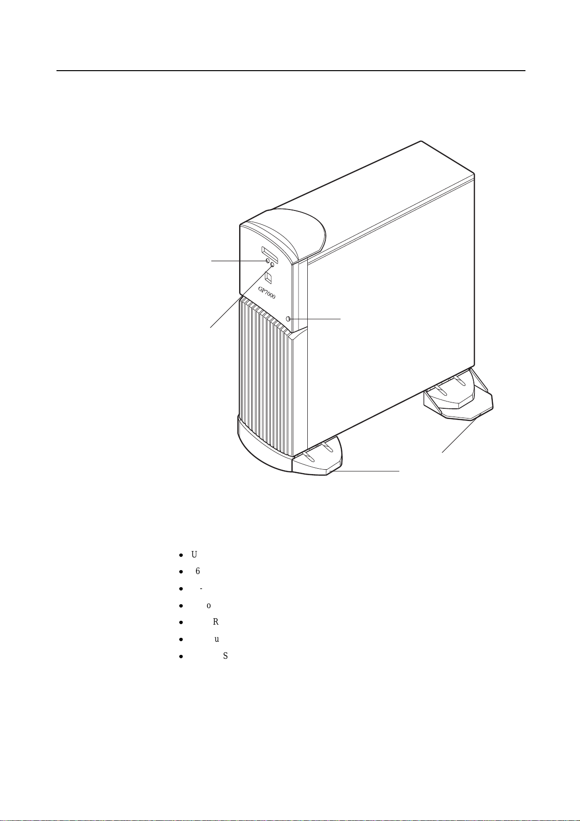
2.1 Overview
Appearance
CHECK LED
( amber )
POWER LED
( green )
Key Features
Lock
Stabilizing Feet
Figure 2.1 Front View of M200 Main Cabinet
Up to 2 processors
16 DIMM slots. Up to 4 gigabytes of memory.
64-bits width, 4 PCI buses provide 6 PCI slots ( 2*33/66MHz + 4*33MHz).
14
Up to 8 UltraSCSI disk drive bays, which support hot-swap features.
1 CD-ROM unit and 1 floppy disk unit as the basic configuration.
1 tape unit can be installed.
1 100BASE-TX (auto-sensing 10/100Mbps), 2 Serial, 1 parallel, and 1 Keyboard/Mouse port
Page 49

2.2 Device Configuration
The M200 main cabinet consists of the following components:
Desk-side type cabinet
Basic power supply and optional expansion power supply unit
Cooling fans
Systemboard
Processor modules
DIMM (Dual Inline Memory Module)
Operator panel
PCI card (option)
SCSI-BP boards (1 basic board, 1 option board)
Disk drive units
CD-ROM unit
Tape unit (optional QIC tape, 8-mm tape, or DAT)
2.2 Device Configuration
Floppy disk unit
The processor modules, DIMMs, PCI cards, tape drive unit, expansion power supply, disk expansion feature
(SCSI-BP board), and disk drive units of the above components are available as options.
15
Page 50

CHAPTER 2 M200 Main Cabinet
Front view of the M200 main cabinet
Operation Panel
Panel Cover
DAT unit,8-mm Tape Unit,
QIC Tape Unit( option )
CD-ROM Unit
Floppy Disk Unit
Front Cover
Panel cover
Stabilizing Feet
Figure 2.2 Open View of M200 Main Cabinet
The panel cover can be opened from its right side after unlocking it. Then, you can access switches
on the operator panel, CD-ROM drive unit, Floppy drive unit, tape drive unit, and so on.
16
Page 51

Fans Table2.1 lists the fans installed in the M200 main cabinet.
Table 2.1 Fans
2.2 Device Configuration
*1 The 80-mm square fan is replaced by the 120-mm square fan when the expansion
Power supplies
The M200 main cabinet has a basic power supply unit as well as DDC(DC-DC Converter)s
dedicated to each processor module. When the Disk Expansion Unit is installed, The expansion
power supply is required (when 5 to 8 disks are installed in the M200 main cabinet).
If the expansion power supply is not installed when the Disk Expansion Unit is installed, an
indication that a mounting rule has been violated is reported on the LCD panel and power-on is
inhibited. This checking function prevents faulty configurations. The checking function is executed
when a disk cage is expanded regardless of whether a disk unit is installed.
The alarm detection feature is not implemented for the expansion power supply of the M200 main
cabinet. If a failure occurs in the expansion power supply, the power cannot be supplied to the Disk
Expansion Unit. In this case, the POWER LED on the disk expansion cage turns off. If an error
occurs in the disk unit installed in the Disk Expansion Unit (because the power is not supplied), the
expansion power supply may be at failed. Check the POWER LED on the expansion disk cage.
Name Shape
Fan #0 120-mm (4.7 inch) square fan
Fan #1 120-mm (4.7 inch) square fan
Fan #2 92-mm (3.6 inch) square fan
Fan #3 80-mm (3.1 inch) or 120-mm
(4.7 inch) square fan (*1)
Fan #4 92-mm (3.6 inch) square fan
power supply is installed.
Location
Behind the Systemboard
Under the disk unit
Above the processor module
Behind the power supply
Side the PCI slot
Stabilizing feet
The stabilizing feet prevent the M200 main cabinet from falling over when it is pushed from its side
or if there is an earthquake. When installing the M200 main cabinet, be sure to install the stabilizing
feet.
Rear of the M200 main cabinet
AC input, AC main line switch, power supply(FEP) and some connectors are located on the rear
panel of the M200 main cabinet as shown in the Figure 2.3 .
17
Page 52
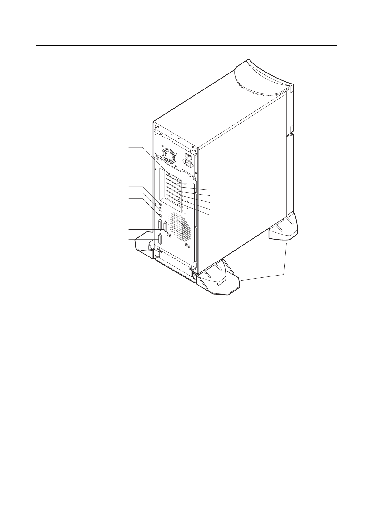
CHAPTER 2 M200 Main Cabinet
RCI
AC Main Line Switch
AC Power Input
UPS
PC
100BASE-TX
Keyboard
RS232C
( Port A)
RS232C
( Port B )
Parallel
( AT Centrenics )
PCI slot #6
PCI slot #5
PCI slot #4
PCI slot #3
PCI slot #2
PCI slot #1
Stabilizing Feet
Figure 2.3 Rear View of M200 Main Cabinet
18
Page 53

2.3 Systemboard
Systemboard layout
2.3 Systemboard
CPU module slots, memory module slots, and PCI slots are located on the Systemboard as described
in Figure 2.4 .
NVRAM
SCF BOARD ONLY
PCI Slot #6
PCI Slot #5
PCI Slot #4
PCI Slot #3
PCI Slot #2
PC LAN KB
Serials Parallel
#13
#12
#9
#8
#5
#4
#1
#0
Processor Configuration
Up to 2 processors can be installed in the M200 main cabinet. When installing the processor
modules, the following conditions must be satisfied:
The installed processor modules must be the same type (including the cache size).
Install a processor module in slot 0 before installing one in slot 1.
When installing a processor module, install DC-DC converters along with the processor in the
corresponding slot.
PCI Slot #1
DDC #3
DDC #2
DDC #1
DDC #0
MEMORY SLOT
CPU #1
CPU #0
Figure 2.4 Systemboard Layout of M200
#15
#14
#11
#10
#7
#6
#3
#2
IMPORTANT
If any of the above conditions is not satisfied, the operation is not guaranteed.
19
Page 54

CHAPTER 2 M200 Main Cabinet
Memory configuration
The M200 has 16 DIMM slots, allowing for as much as 4 gigabytes of main memory. When
installing the DIMMs, the following conditions must be satisfied:
IMPORTANT
If any of the above conditions is not satisfied when installing the DIMMs, some DIMMs are
degraded in the power-on diagnostics. When adding the memory modules, check that the
DIMMs are installed correctly.
Memory ECC feature
The EDO DRAM is used as the memory element. The single-bit error correction and multiple-bits
error detection features are available for a large capacity memory by using the Error Check Code
(ECC) system. A single-bit error can be isolated down to the memory slot on which it occurred. A
multiple-bit error can be isolated down to the pair of slots on which it occurred.
When installing the first set of DIMM, install a set of 4 modules of the same size in slots 0 to 3.
At subsequent memory expansions, install a set of 4 modules of the same size in slots 4, 5, 6, 7;
and 8, 9, 10, 11; then 12, 13, 14, 15.
Checking the memory diagnostics
Tocheck that the system recognizes installed memory modules correctly, execute the
show-post-results command at the ok prompt. A module that does not satisfy any condition
described in "Memory configuration" or a module judged to be faulty by memory diagnostics is
treated as an invalid module. The screen below lists the command execution results related to
memories and their meanings.
Example for normal operation
=== Memory =========
Type : EDO
SLOT# Size[Valid(MB)/Existing(MB) Total
0-3 32/32 32/32 32/32 32/32 : 128/128 MB
4-7 32/32 32/32 32/32 32/32 : 128/128 MB
8-11 ----- ----- ----- ----- : 0/0 MB
12-15 ----- ----- ----- ----- : 0/0 MB
*=Error SLOT
In this example, a memory module has been placed in degraded mode.
=== Memory =========
Type : EDO
SLOT# Size[Valid(MB)/Existing(MB) Total
0-3 32/32 32/32 32/32 32/32 : 128/128 MB
4-7 0/32 0/0* 0/32 0/32 : 0/96 MB
8-11 ----- ----- ----- ----- : 0/0 MB
12-15 ----- ----- ----- ----- : 0/0 MB
*=Error SLOT
20
Page 55

2.4 Disk Units
Disk drive configuration
2.4 Disk Units
The denominator indicates the size of the memory module for a slot (unit: megabytes); 0* indicates
a faulty slot. The numerator indicates the size of the memory that is actually available for use. The
numerator 0 indicates that no memory is used.
In this example, DIMMs are installed in slots 0 to 7. The size of each module is 32 megabytes
except the one installed in slot 5. The initial system diagnostics detected an error in the module
installed in slot 5 and placed the module in degraded mode, assuming there was no available space.
As a result, the group of modules in slots 4 to 7 is not available for use.
When the Disk Expansion Unit (which includes an expansion disk cage) is added, up to 8 disk units
can be installed in the M200 main cabinet. Basic disk cage (bay #0-#3) is connected to UltraSCSI
bus, and the expansion disk cage (bay #0-#3) is connected to another UltraSCSI bus. Each disk
drive has two status LEDs. For the status of these LEDs, refer to 11 , "Input-Output Units."
ACTIVE LED( Green )
FAULT LED( Amber )
Expansion disk cage
POWER LED
Basic disk cage
Figure 2.5 Disk Drive Bays of M200 Main Cabinet
#0
#0
#1
#1
#2 #3
#2 #3
21
Page 56

CHAPTER 2 M200 Main Cabinet
Disk Expansion Unit
By using the Disk Expansion Unit, up to 8 disk drives can be installed in the M200 main cabinet.
The Disk Expansion Unit consists of the following components:
A Power LED is installed on the SCSI-BP board. If both ACTIVE LED and FAULT LED above a
disk bay do not lights, check to see if the POWER LED on the SCSI-BP board is turned on. If this
POWER LED does not turn on, disk expansion unit or its cable may be faulty.
When installing the Disk Expansion Unit, the installed location (slot) of the PCI card used for
connection must be set. Below shows the setting procedure.
Disk cage (including SCSI-BP)
PCI adapter (UltraSCSI Wide Single-Ended)
Expansion power supply unit (requires changing to 120-mm (4.7 inch) square fan: included)
Cables
Be sure to replace the power supply fan when installing the Disk
CAUTION
Expansion Unit. Otherwise, the system will shutdown or disk units
will deteriorate due to a temperature rise in the M200 main cabinet
caused by insufficient cooling.
1 First, execute show-scsi command at the ok prompt, to get the path name of the UltraSCSI
card and it’s PCI slot. The followings example shows that a Ultra SCSI card is installed in PCI
slot#6.
ok show-scsi
PCI#6 : /pci@1d,4000/scsi@5,1
PCI#6 : /pci@1d,4000/scsi@5
SCSI#0: /pci@1f,4000/scsi@3
ok
2 Then, set led-control-1 to correspond to the PCI slot by using setenv command at the
ok prompt. The followings example shows that a Disk Expansion Unit connection to SCSI
Conector #1 of the UltraSCSI card in PCI slot#6.
ok setenv led-control-1 /pci@1d,4000/scsi@5
If the installing location (slot) is not set or set incorrectly, the disk
CAUTION
drive may not be hot-swappable. Data may be destroyed as a
result of inadvertently replacing the different disk drive. Be sure to
set the installing location (slot) correctly.
Also, while replacing or initializing NVRAM, set the installing
location again.
22
Page 57
2.5 PCI Slots
PCI slots configuration
2.5 PCI Slots
PCI slots are located on the Systemboard as described in Figure 2.4 , and each PCI slots has the
following specifications. There are 4 separate PCI Bus channels: A, B, C, and D. All PCI slots
provide for the full 64-bit data path and can accommodate both 32-bit and 64-bit data path cards.
The specifications for the PCI slots are described in Table 2.2 .
Table 2.2 PCI Slot Specifications
PCI slot # PCI Bus Slot width / card width PCI clock Card input voltage
(bits) (MHz)
6 D
5 D
4 D
3 C
2 B
1 A
64 / 32,64 33 5 V or Universal
64 / 32,64 33 5 V or Universal
64 / 32,64 33 5 V or Universal
64 / 32,64 33 5 V or Universal
64 / 32,64 33 / 66 3.3 V or Universal
64 / 32,64 33 / 66 3.3 V or Universal
2.6 Installation
Notes on installation:
Do not block the ventilation slits.
Do not install the M200 main cabinet where it will be exposed to sunlight or sources of heat.
Do not install the M200 main cabinet in dusty places or places where it will be exposed to
corrosive gas or sea breeze.
Keep the M200 main cabinet isolated from vibration. Install the M200 main cabinet on a level
surface so that it does not tilt.
Make sure that the AC power supply source is grounded properly. Otherwise, the M200 main
cabinet may malfunction.
Do not run a cable under a unit or allow a cable to become taut. Do not disconnect the power
cable when the power is on.
Do not place anything on the M200 main cabinet. Do not use the cabinet of the M200 main
cabinet as a work space.
To prevent condensation in the M200 main cabinet, do not raise the ambient temperature
rapidly, in winter. Use the M200 main cabinet only after it has warmed up sufficiently.
Do not install the M200 main cabinet near a noise generating device such as a photocopier, air
conditioner, or welder.
Take electrostatic prevention measures. Note that some carpets generates static electricity
easily and can cause the M200 main cabinet to malfunction.
When moving the M200 main cabinet, do not pull on the front cover. Otherwise, the main
cabinet may be damaged.
23
Page 58

CHAPTER 2 M200 Main Cabinet
IMPORTANT
If the above conditions are not satisfied, the M200 main cabinet may be damaged. Be sure
to follow these precautions.
Installation specifications
Item Specification
Mass Up to 43kg (approx.94.9 lb)
Power condition Input voltage
Maximum consumption current 5.0 A
Leakage current 3.5 mA or less
Ground resistance 100ohm or less ( class C installation standard)
Temperature condition Operating 5 to 35 degrees Celsius (+41 to +95 F) (*1)
Humidity condition Operating 20 to 80%RH (no condensation)
Vibrations condition Operating 0.2 G
Noise 47 db (A) (*2)
Installation standalone type
Table 2.3 Installation Specifications of M200 Main Cabinet (1)
Single phase
100 to 120 VAC
(+-10%)
Input frequency
Not operating 0 to 50 degrees Celsius (+32 to +122F)
Not operating 8 to 80% RH (no condensation)
Idle 0.4 G
50/60 Hz (+2 to -4%)
Single phase
200 to 240 VAC
(+-10%)
2.5 A
3.5 mA or less
24
*1: If the ambient temperature exceeds 35 degrees Celsius (+95 F) during operation, a
warning message is displayed. Take steps to rectify the problem immediately.
*2: The indicated noise is the mean value of the measurements obtained in an anechoic
chamber with less echoic influence. The actual noise measured at the installation site
may be greater than the indication noise due to surrounding noise and echoes.
Page 59

Table 2.4 Installation Specifications of M200 Main Cabinet (2)
Item Specification
External
dimension
(unit:mm)
Height 700
Service
area
(unit:mm)
Width 230 Depth 630
352 677
*1
(Front View) (Side View)
230
Service area
800
2.6 Installation
*2
800 800
*3 *3
Service area Service area
Top of
the unit
Front
Service area
630
800
*1: The unit width including the Stabilizing Feet is 352 mm (13.9 inch).
*2: For the rear space, if 800 mm (31.5 inch) or more space is available by moving the
cabinet when repair the cabinet or provide any services for it, 200 mm (7.8 inch) of
space is acceptable for regular use. However, when optical cables are laid out, more
than 300 mm (11.8 inch) of space between the rear side of the unit and wall is
required.
*3: For the side space, if 800 mm (31.5 inch) or more space is available by moving the
cabinet when repair the cabinet or provide any services for it, the service area as
described in Table 2.4 is not necessary for regular use.
*4: A minimum of 50 mm (1.9 inch) of clearance is required above the top of the unit.
*5: The unit depth of the cabinet at the bottom including the skirt is 677 mm (26.7 inch).
25
Page 60

Page 61

CHAPTER 3 M200R Main Cabinet
CONTENTS
3.1 Overview .................................................................................... 28
3.2 Device Configuration ........................................................................ 29
3.3 Systemboard ................................................................................. 32
3.4 Disk Units .................................................................................... 34
3.5 PCI Slots .................................................................................... 35
3.6 Installation .................................................................................... 36
3
27
Page 62
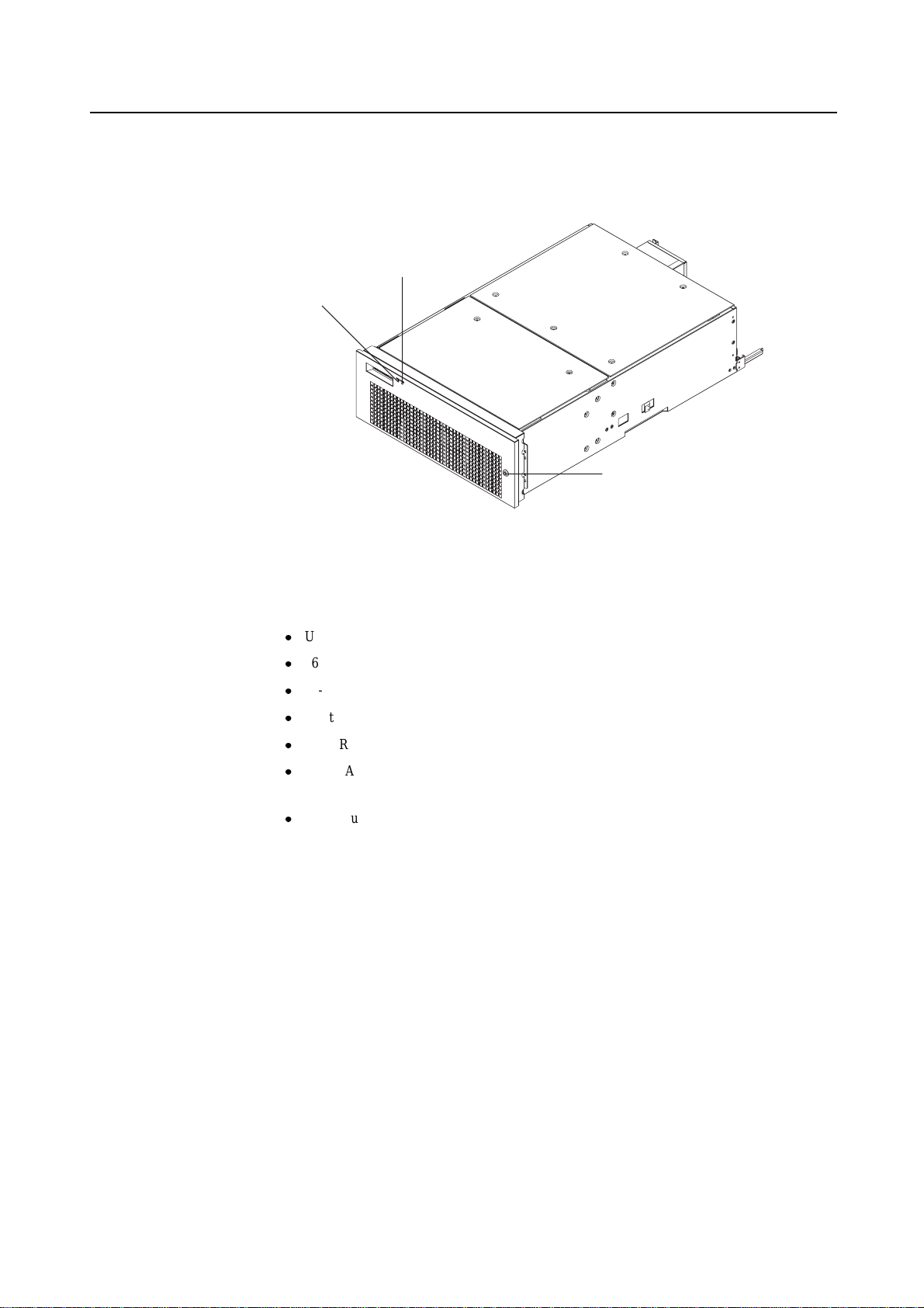
CHAPTER 3 M200R Main Cabinet
3.1 Overview
Appearance
CHECK LED (amber)
POWER LED (green)
Lock
Figure 3.1 Front View of M200R Main Cabinet
Key Features
Up to 2 processors
16 DIMM slots, up to 4 gigabytes of memory.
64-bits width, 4 PCI buses provide 6 PCI slots ( 2*33/66MHz + 4*33MHz).
2 UltraSCSI disk drive bays, which support hot-swap features.
1 CD-ROM unit and 1 floppy disk unit as the basic configuration.
1 100BASE-TX (auto-sensing 10 / 100 Mbps), 1 UltraSCSI(differencal), 2 Serial, 1 Parallel, 1
Keyboard/Mouse port
N+1 redundant power supply units, and fan units, which support hot-swap feature.
28
Page 63

3.2 Device Configuration
The M200R main cabinet consists of the following components:
RackMount type cabinet
Basic power supply and option redundant power supply unit
Cooling fans
Systemboard
Processor modules
DIMM (Dual Inline Memory Module)
Operator panel
PCI card (option)
Disk drive units
CD-ROM unit
Floppy disk unit
The processor modules, DIMMs, PCI cards, redundant power supply, and disk drive units of the above
components are available as options.
3.2 Device Configuration
Front view of the M200R main cabinet
Operator Panel
Panel Cover
CD-ROM Unit
Floppy Disk Unit
Figure 3.2 Open View of M200R Main Cabinet
Panel cover
The panel cover can be opened from its right side after unlocking it. Then you can access switches
on the operator panel, CD-ROM unit, Floppy drive unit, and so on.
29
Page 64

CHAPTER 3 M200R Main Cabinet
Fans The Table3.1 lists the fans installed in the M200R main cabinet.
Power supplies
The M200R main cabinet has 2 kinds of power supply units as well as DDC (DC-DC Converter).
FEP (Front End Bulk Power) unit has AC input, and provide +48V(to BE). BE (Back End Power)
has +48V input, and provide +12V or +5V or +3.3V to some internal components.
Table 3.1 Fans
Name Tray # Location
Fan #0 Tray #0 Right (front view) of the cabinet
Fan #1
Fan #2 Tray #1 Left (front view) of the cabinet
Fan #3
Fan #10 Tray #5 Rear of the cabinet
Fan #11
Fan #14 Tray #7 Above the processer module
Fan #15
Fan #16 Tray #8 Side the PCI slot
Fan #17
Table 3.2 Power Supply Units
Standard Redundant
FEP
BE(5V)
BE(3.5V)
1
2
2
2
3
3
30
Page 65

Rear of the M200R main cabinet
AC input, power supplies (FEP) and some connectors are located on the rear of the M200R main
cabinet as shown in the Figure 3.3
RCI
FEP#0
UPS
PCI slot
3.2 Device Configuration
AC Power Input FEP#1(option)
Parallel
RS232C
(portB)
RS232C
(portA)
SCSI
Power Control 100BASE-TX
Keyboard
Figure 3.3 Rear View of M200R Main Cabinet
31
Page 66

CHAPTER 3 M200R Main Cabinet
3.3 Systemboard
Systemboard
CPU module slots and memory module slots are located on Systemboard as described in Figure 3.4 .
DIMM Slot #1
DIMM Slot #3
DIMM Slot #5
DIMM Slot #7
DIMM Slot #9
DIMM Slot #11
DIMM Slot #13
DIMM Slot #15
NVRAM
DDC#0
DDC#1
DIMM Slot #14
DIMM Slot #12
DIMM Slot #10
DIMM Slot #8
DIMM Slot #6
DIMM Slot #4
DIMM Slot #2
DIMM Slot #0
CPU Slot #0
CPU Slot #1
DDC#2
DDC#3
DDC#4
PCI Slot #1
PCI Slot #2
PCI Slot #3
PCI Slot #4
PCI Slot #5
PCI Slot #6
32
Figure 3.4 Systemboard Layout of M200R
Page 67

Processor Configuration
Up to 2 processors can be installed in the M200R main cabinet. When installing the processor
modules, the following conditions must be satisfied:
The installed processor modules must be the same type (including the cache size).
Install a processor module in slot 0 before installing one in slot 1.
When installing a processor module, install DC-DC converters along with the processor in the
corresponding slot.
IMPORTANT
If any of the above conditions is not satisfied, the operation is not guaranteed.
Memory configuration
The M200R has 16 memory slots, allowing for as much as 4 gigabytes of main memory. When
installing the memory modules, the following conditions must be satisfied:
When installing the first set of DIMM, install a set of 4 modules of same size in slots 0, 1, 2,
and 3.
3.3 Systemboard
At subsequent memory expansions, install a set of 4 modules of the same size in slots 4, 5, 6, 7,
and 8, 9, 10, 11, then 12, 13, 14, 15.
IMPORTANT
If any of the above conditions is not satisfied when installing the DIMMs, some DIMMs are
degraded in the power-on diagnostics. When expanding the memory modules, check that
the DIMMs are installed correctly.
Memory ECC feature
The SDRAM is used as the memory chip. The single-bit error correction and multiple-bit error
detection features are available for a large capacity memory by using the Error Check Code (ECC)
system. A single-bit error can be isolated down to the memory slot on which it occurred. A
multiple-bit error can be isolated down to the pair of slots on which it occurred.
Checking results of the memory diagnostics
Tocheck that the system recognizes installed memory modules correctly, execute the
"show-post-results" command at the ok prompt. A module that does not satisfy any
condition described in "Memory configuration" or a module judged to be faulty by memory
diagnostics is treated as an invalid module. The screen below lists the command execution results
related to memories and their meanings.
33
Page 68

CHAPTER 3 M200R Main Cabinet
Example for normal operation
=== Memory ===================
Type : SDRAM
SLOT# Size [ Valid (MB) / Existing (MB) ] Total
00- 0- 3 256 / 256 256 / 256 256 / 256 256 / 256 : 1024 / 1024 MB
00- 4- 7 256 / 256 256 / 256 256 / 256 256 / 256 : 1024 / 1024 MB
00- 8-11 256 / 256 256 / 256 256 / 256 256 / 256 : 1024 / 1024 MB
00-12-15 256 / 256 256 / 256 256 / 256 256 / 256 : 1024 / 1024 MB
* = Error SLOT
Example of a slot #4 error
=== Memory ===================
Type : SDRAM
SLOT# Size [ Valid (MB) / Existing (MB) ] Total
00- 0- 3 256 / 256 256 / 256 256 / 256 256 / 256 : 1024 / 1024 MB
00- 4- 7 0 / 0* 0 / 256 0 / 256 0 / 256 : 0 / 768 MB
00- 8-11 256 / 256 256 / 256 256 / 256 256 / 256 : 1024 / 1024 MB
00-12-15 256 / 256 256 / 256 256 / 256 256 / 256 : 1024 / 1024 MB
* = Error SLOT
3.4 Disk Units
Disk drive configuration
Note: If a memory error is detected, an asterisk is displayed in the Size field for the
corresponding slot. In this example, an error in slot #4 is detected in the initial
diagnostics operation. Modules in slots 5 to 7 are recognized as normal modules but
also become invalid.
Up to 2 disk drives can be installed in the base configuration of the M200R main cabinet. To install
more than 3 disk drive units, the Expansion File Unit must also installed.
34
Page 69

3.5 PCI Slots
PCI slots configuration
3.5 PCI Slots
PCI slots are located on the Systemboard as described in Figure 3.4 . There are 4 separate PCI Bus
channels: A, B, C, and D. All PCI Bus slots provide for the full 64-bit data path and can
accommodate both 32-bit and 64-bit data path cards. The specifications for the PCI slots are
described in the Table3.3 .
Table 3.3 PCI Slot Specifications
PCI slot # PCI Bus Slot width / card PCI clock Card input voltage
width (bits) (MHz)
6 D
5 D
4 D
3 C
2 B
1 A
64 / 32, 64 33 5 V or Universal
64 / 32, 64 33 5 V or Universal
64 / 32, 64 33 5 V or Universal
64 / 32, 64 33 5 V or Universal
64 / 32, 64 33 / 66 3.3 V or Universal
64 / 32, 64 33 / 66 3.3 V or Universal
35
Page 70

CHAPTER 3 M200R Main Cabinet
3.6 Installation
Purpose The following installation instruction is intended to provide the product safety requirements which
must be addressed when the end-use product manufacturer installs this product in their equipment.
Note that the acceptability of the combination of this product in a rack should be re-determined by
an appropriate certification body, if that combination is differ from the Table 3.4 .
Safety Installation Instruction:
This unit is installed in a closed or multi-unit rack assembly, the operating ambient temperature
inside of the rack environment may be greater than room ambient. Therefore, consideration
should be given to installing the unit in an environment compatible with the manufacturer’s
maximum rated ambient temperature.
– Consideration for adjustment of air condition like air circulation should be given to prevent
the internal rack ambient from exceeding the Max. Operating ambient temperature of this
unit.
– Maximum operating ambient temperature of this unit : 35 deg C.
Installation of the unit in a rack should be such that the amount of air flow required for safe
operation of the unit is not compromised.
– This unit has ventilation openings at front and rear face of the unit.
– Do not cover or close these ventilation openings to prevent overheating.
Mounting of the unit in the rack should be such that a hazardous condition is not achieved due
to uneven mechanical loading. To keep stability of entire rack, please fix the rack to wall or
floor by suitable means.
– Be careful about injury during installation of this unit into rack.
– Do not install this unit into your rack where the unit may make the entire rack unstable.
– Mass of this unit with maximum configuration : 40 kg.
If the unit is supplied from Power Strip or Service Outlet of other units, it may overload the
Power Supply Cord of the Power Strip or other units.
– Confirm that the current rating of Power Strip or Service Outlet exceeds the combined
ratings of all equipment it is supplying.
– Electrical ratings of this unit : Rated 100 - 240Vac, 4.0 - 1.5 A, 50/60 Hz, 1 phase
Reliable earthing of rack-mounted equipment should be maintained. Particular attention should
be given to supply connections other than direct connections to the branch circuit (e.q., use of
power strips).
36
Page 71

3.6 Installation
IMPORTANT
High Leakage Current may flow through Power Strip Earthing Conductor, if all power
supply cords of this unit are connected to one Power Strip. Earth connection essential
before connecting supply.
Table 3.4 Mounting Combination for Expansion Rack
Communication Swichable Unit
Note: Each rack-mount unit should be mounted in the lowest available portion with the
Notes on Installation
Do not install this file unit where it will be exposed to sunlight or sources of heat.
Do not install this file unit in dusty places or places where it will be exposed to corrosive gas or
sea breeze.
Keep this file unit isolated from vibration. Install this file unit on a level surface to prevent it
from tilting.
Rack-Mount Units
Expansion File Unit Type-2
Disk Array Unit (GP-DxxxxU)
GP7000F Model 200R/400R
Disk Array Unit (GR700/720)
Outlet and/or Outlet Type-2
GP7000F Model 600R
priority indicated in the Table 3.4 .
Mounting Portion Priority in the Rack
Upper
Lower
Do not run a cable under a unit or overextend a cable. Do not disconnect the power cable while
the power is on.
Do not place anything on this file unit. Do not use this file unit as a desk.
Toprevent condensation in this file unit, do not raise the room temperature rapidly in the winter.
Use the cabinet only after sufficiently warming it.
Do not install this cabinet near noisy devices such as a photocopier, air conditioner, or welder.
Take electrostatic prevention measures. Note that some carpets generate static electricity easily
and can cause this file unit to malfunction.
IMPORTANT
If the above conditions are not satisfied, this file unit may be damaged. Be sure to follow
above precautions.
37
Page 72

CHAPTER 3 M200R Main Cabinet
Installation specifications
Item Specification
Mass Up to 40kg (approx.88 lb)
Power condition Input voltage
Maximum consumption current 4.0 A
Leakage current (1 for each cable) 3.5 mA or less
Ground resistance 100ohm or less ( class C installation standard)
Temperature condition Operating 5 to 35 degrees Celsius (+41 to +95 F) (*1)
Humidity condition Operating 20 to 80%RH (no condensation)
Vibrations condition Operating 0.2 G
Noise 50 db (A) (*2)
Installation Rack mount type (4pitches)
Table 3.5 Installation Specifications of M200R (1)
Single phase
100 to 120 VAC
(+-10%)
Input frequency
Not operating 0 to 50 degrees Celsius (+32 to +122F)
Not operating 8 to 80% RH (no condensation)
Idle 0.4 G
50/60 Hz (+2 to -4%)
Single phase
200 to 240 VAC
(+-10%)
2.0 A
3.5 mA or less
*1: If the ambient temperature exceeds 35 degrees Celsius (+95F) during operation, a
warning message is displayed. Take steps to rectify the problem immediately.
*2: The indicated noise is the mean value of the measurements obtained in an anechoic
chamber with less echoic influence. The actual noise measured at the installation site
may be greater than the indication noise due to surrounding noise and echoes.
38
Page 73

Table 3.6 Installation Specifications of M200R (2)
Item Specification
External
dimension
(unit:mm)
Height 174
Width 482
3.6 Installation
Depth 779
Service
area
(unit:mm)
(Front of the cabinet)
800
Service area
*2
650
*3
695
Rear
Service area
Top of
the cabinet
Drawer area
*1
Front
Service area
(Side of the cabinet)
800
Service area
1000
930
925
800
800
*2
*3
*1: Keep the drawer area so that the CPU shelf can be pulled out from the main cabinet
during installing some internal option products and providing maintenance of the
CPU shelf.
*2: When this unit is installed in a expansion rack:GP7B7RK1U/RK2U/RK3U/RK4U.
*3: When this unit is installed in a expansion rack:GP727RK1U/RK2U.
39
Page 74

Page 75

CHAPTER 4 M400A Main Cabinet
CONTENTS
4.1 Overview .................................................................................... 42
4.2 Device Configuration ........................................................................ 43
4.3 Systemboard ................................................................................. 46
4.4 Disk Units .................................................................................... 48
4.5 PCI Slots .................................................................................... 49
4.6 Installation .................................................................................... 50
4
41
Page 76

CHAPTER 4 M400A Main Cabinet
4.1 Overview
Appearance
CHECK LED
(amber)
POWER LED
(green)
Lock
Figure 4.1 Front View of M400A Main Cabinet
Key Features
Up to 4 processors
Up to 32 DIMM slots, 8 gigabytes of memory.
Up to 64-bits width, 8 PCI buses provide 12 PCI slots ( 4*33/66MHz + 8*33MHz).
Up to 22 UltraSCSI disk drive bays, which support hot-swap features.
1 CD-ROM unit and 1 floppy disk unit as the basic configuration.
1 tape unit can be installed.
1 100BASE-TX (auto-sensing 10 / 100 Mbps), 2 Serial, 1 Parallel, 1 Keyboard/Mouse port
N+1 redundant power supply units, and fan units, which support hot-swap feature.
42
Page 77

4.2 Device Configuration
The M400A main cabinet consists of the following components:
Floor stand cabinet
Basic power supply and option redundant power supply unit
Cooling fans
Systemboard
Processor modules
DIMM (Dual Inline Memory Module)
Operator panel
PCI card (option)
Disk drive units
CD-ROM unit
Tape unit (optional QIC tape, 8-mm tape, or DAT)
Floppy disk unit
4.2 Device Configuration
The processor modules, DIMMs, PCI cards, tape drive unit, redundant power supply, and disk drive units of the
above components are available as options.
Front view of the M400A main cabinet
DAT Unit / 8mm Tape Unit
/ QIC Tape Unit
Operator Panel
Floppy Disk Unit
Panel Cover
CD-ROM Unit
Figure 4.2 Open View of M400A Main Cabinet
43
Page 78

CHAPTER 4 M400A Main Cabinet
Panel cover
The panel cover can be opened from its right side after unlocking it. Then you can access switches
on the operator panel, CD-ROM unit, Floppy drive unit, tape unit, and so on.
Fans The Table4.1 lists the fans installed in the M400A main cabinet.
Table 4.1 Fans
Name Tray # Location
Fan #0 Tray #04 Right (front view) of the cabinet
Fan #1
Fan #3 Tray #01 Center (front view) of the cabinet
Fan #4 Tray #02 Left (front view) of the cabinet
Fan #5
Fan #10 Tray #05 Bottom (rear view) of the cabinet
Fan #11
Fan #12 Tray #06 Upper (rear view) of the cabinet
Fan #13
Fan #14 Tray #07 Above the processer module
Fan #15
Fan #16 Tray #08 Side the PCI slot
Fan #17
Fan #18 Tray #09 Above the processer module (System expansion unit)
Fan #19
Fan #20 Tray #10 Side the PCI slot (System expansion unit)
Fan #21
44
Power supplies
The M400A main cabinet has 2 kinds of power supply units as well as DDC (DC-DC Converter).
FEP (Front End Bulk Power) unit has AC input, and provide +48V(to BE). BE (Back End Power)
has +48V input, and provide +12V or +5V or +3.3V to some internal components. The power
supplies must be configured according to the system hardware configuration as described in
Table4.2 .
Table 4.2 Power Supply Units
Without an Expansion With an Expansion
System Board System Board
Standard Redundant Standard Redundant
FEP
BE(5V)
BE(3.5V)
2 3 3 4
3 4 5 6
2 3 3 4
Page 79

Rear of the M400A main cabinet
AC input, AC main line switch, power supplies (FEP) and some connectors are located on the rear
of the M400A main cabinet as shown in the Figure 4.3
PCI slot
4.2 Device Configuration
SCSI
(Differential)
UPS
RCI
AC Main Line
Switch
SCSI
(Differential)
100BASE-TX
FEP#2
FEP#0
AC Mainline Switch
Expansion System Board
(option)
FEP#3 (option)
100BASE-TX
FEP#1
RS232C (portB)
RS232C (portA)
Parallel
Keyboard
Expansion File Unit Type-2
(option)
AC Power Input
Figure 4.3 Rear View of M400A Main Cabinet
45
Page 80

CHAPTER 4 M400A Main Cabinet
4.3 Systemboard
Systemboard
CPU module slots and memory module slots are located on Systemboard as described in Figure 4.4 .
00-DIMM Slot #1
00-DIMM Slot #3
00-DDC #0
NVRAM
00-DIMM Slot #5
00-DIMM Slot #7
00-DIMM Slot #9
00-DIMM Slot #11
00-DIMM Slot #13
00-DDC #1
00-DDC #2
00-DIMM Slot #15
00-DDC #3
00-CPU Slot #0
00-DDC #4
00-CPU Slot #1
00-PCI Slot #1
00-PCI Slot #2
00-PCI Slot #3
00-PCI Slot #4
00-PCI Slot #5
00-PCI Slot #6
00-DIMM Slot #14
00-DIMM Slot #12
00-DIMM Slot #10
00-DIMM Slot #8
00-DIMM Slot #6
00-DIMM Slot #4
00-DIMM Slot #2
00-DIMM Slot #0
NVRAM
01-DIMM Slot #1
01-DIMM Slot #3
01-DIMM Slot #5
01-DIMM Slot #7
01-DIMM Slot #9
Base System Board
01-DDC #0
01-DDC #1
01-DDC #2
01-DDC #3
01-DDC #4
01-PCI Slot #1
01-CPU Slot #0
01-CPU Slot #1
01-DIMM Slot #11
01-DIMM Slot #13
01-DIMM Slot #15
Expansion System Board
Figure 4.4 Systemboard Layout of M400A
01-PCI Slot #2
01-PCI Slot #3
01-PCI Slot #4
01-PCI Slot #5
01-PCI Slot #6
01-DIMM Slot #14
01-DIMM Slot #12
01-DIMM Slot #10
01-DIMM Slot #8
01-DIMM Slot #6
01-DIMM Slot #4
01-DIMM Slot #2
01-DIMM Slot #0
46
Page 81

Processor Configuration
Up to 4 CPU can be installed in the M400A main cabinet. When installing the processor modules,
the following conditions must be satisfied:
The installed processor modules must be the same type (including the cache size).
Install a processor module in slot 0 before installing one in slot 1.
When installing a processor module, install DC-DC converters alog with the processor in the
corresponding slot.
IMPORTANT
If any of the above conditions is not satisfied, the operation is not guaranteed.
Memory configuration
Using the Expansion System Board’s option the M400A has 32 memory slots, allowing for as much
as 8 gigabytes of main memory. When installing the memory modules, the following conditions
must be satisfied:
4.3 Systemboard
When installing the first set of DIMM, install a set of 4 modules of same size in slots 0, 1, 2,
and 3.
At subsequent memory expansions, install a set of 4 modules of the same size in slots 4, 5, 6, 7,
and 8, 9, 10, 11, then 12, 13, 14, 15.
The same memory installation rules ( described above ) apply when using the Expansion
System Board.
IMPORTANT
If any of the above conditions is not satisfied when installing the DIMMs, some DIMMs are
degraded in the power-on diagnostics. When expanding the memory modules, check that
the DIMMs are installed correctly.
Memory ECC feature
The SDRAM DRAM is used as the memory chip. The single-bit error correction and multiple-bit
error detection features are available for a large capacity memory by using the Error Check Code
(ECC) system. A single-bit error can be isolated down to the memory slot on which it occurred. A
multiple-bit error can be isolated down to the pair of slots on which it occurred.
Checking results of the memory diagnostics
Tocheck that the system recognizes installed memory modules correctly, execute the
"show-post-results" command at the ok prompt. A module that does not satisfy any
condition described in "Memory configuration" or a module judged to be faulty by memory
diagnostics is treated as an invalid module. The screen below lists the command execution results
related to memories and their meanings.
47
Page 82

CHAPTER 4 M400A Main Cabinet
Example for normal operation
=== Memory ===================
Type : SDRAM
SLOT# Size [ Valid (MB) / Existing (MB) ] Total
00- 0- 3 256 / 256 256 / 256 256 / 256 256 / 256 : 1024 / 1024 MB
00- 4- 7 256 / 256 256 / 256 256 / 256 256 / 256 : 1024 / 1024 MB
00- 8-11 256 / 256 256 / 256 256 / 256 256 / 256 : 1024 / 1024 MB
00-12-15 256 / 256 256 / 256 256 / 256 256 / 256 : 1024 / 1024 MB
01- 0- 3 256 / 256 256 / 256 256 / 256 256 / 256 : 1024 / 1024 MB
01- 4- 7 256 / 256 256 / 256 256 / 256 256 / 256 : 1024 / 1024 MB
01- 8-11 256 / 256 256 / 256 256 / 256 256 / 256 : 1024 / 1024 MB
01-12-15 256 / 256 256 / 256 256 / 256 256 / 256 : 1024 / 1024 MB
* = Error SLOT
Example of a slot #4 error
=== Memory ===================
Type : SDRAM
SLOT# Size [ Valid (MB) / Existing (MB) ] Total
00- 0- 3 256 / 256 256 / 256 256 / 256 256 / 256 : 1024 / 1024 MB
00- 4- 7 0 / 0* 0 / 256 0 / 256 0 / 256 : 0 / 768 MB
00- 8-11 256 / 256 256 / 256 256 / 256 256 / 256 : 1024 / 1024 MB
00-12-15 256 / 256 256 / 256 256 / 256 256 / 256 : 1024 / 1024 MB
01- 0- 3 256 / 256 256 / 256 256 / 256 256 / 256 : 1024 / 1024 MB
01- 4- 7 256 / 256 256 / 256 256 / 256 256 / 256 : 1024 / 1024 MB
01- 8-11 256 / 256 256 / 256 256 / 256 256 / 256 : 1024 / 1024 MB
01-12-15 256 / 256 256 / 256 256 / 256 256 / 256 : 1024 / 1024 MB
* = Error SLOT
4.4 Disk Units
Disk drive configuration
Note: If a memory error is detected, an asterisk is displayed in the Size field for the
corresponding slot. In this example, an error in slot #4 is detected in the initial
diagnostics operation. Modules in slots 5 to 7 are recognized as normal modules but
also become invalid.
Up to 7 disk dirves can be installed in To install more than 8 disk drive units, the File Unit
Expansion Kit and/or Expansion File Unit Type-2 must be installed.
48
Page 83

4.5 PCI Slots
PCI slots configuration
4.5 PCI Slots
PCI slots are located on the systemboard as described in Figure 4.4 . There are 7 separate PCI Bus
channels: A, B, C, D, E, F, G, and H. All PCI Bus slots provide for the full 64-bit data path and can
accommodate both 32-bit and 64-bit data path cards. The specifications for the PCI slots are
described in the Table4.3 .
Table 4.3 PCI Slot Specifications
PCI slot # PCI Bus Slot width / card PCI clock Card input voltage
width (bits) (MHz)
D 64 / 32, 64 33
(00)
D 64 / 32, 64 33
D 64 / 32, 64 33
C 64 / 32, 64 33
B 64 / 32, 64 33 / 66
A 64 / 32, 64 33 / 66
H 64 / 32, 64 33
(01)
H 64 / 32, 64 33
H 64 / 32, 64 33
G 64 / 32, 64 33
F 64 / 32, 64 33 / 66
E 64 / 32, 64 33 / 66
6
5
4
3
2
1
6
5
4
3
2
1
5 V or universal
5 V or universal
5 V or universal
5 V or universal
3.3 V or universal
3.3 V or universal
5 V or universal
5 V or universal
5 V or universal
5 V or universal
3.3 V or universal
3.3 V or universal
Note: When you use 7 PCI slots or more, optional PCI Extension System Board must be
added to the M400R main cabinet.
49
Page 84

CHAPTER 4 M400A Main Cabinet
4.6 Installation
Notes on installation:
Do not block the ventilation slits.
Do not install the M400A main cabinet where it will be exposed to sunlight or sources of heat.
Do not install the M400A main cabinet in dusty places or places where it will be exposed to
corrosive gas or sea breeze.
Keep the M400A main cabinet isolated from vibration. Install the M400A main cabinet on a
level surface so that it does not tilt.
Make sure that the AC power supply source is grounded properly. Otherwise, the M400A main
cabinet may malfunction.
Do not run a cable under a unit or allow a cable to become taut. Do not disconnect the power
cable when the power is on.
Do not place anything on the M400A main cabinet. Do not use the cabinet of the M400A main
cabinet as a work space.
In winter, to prevent condensation in the M400A main cabinet, do not raise the ambient
temperature rapidly. Use the M400A main cabinet only after it has warmed up sufficiently.
Do not install the M400A main cabinet near a noise generating device such as a photocopier, air
conditioner, or welder.
Take electrostatic prevention measures. Note that some carpets generates static electricity
easily and can cause the M400A main cabinet to malfunction.
When moving the M400A main cabinet, do not pull on the front cover. Otherwise, the main
cabinet may be damaged.
IMPORTANT
If the above conditions are not satisfied, the M400A main cabinet may be damaged. Be
sure to follow these precautions.
50
Page 85

Installation specifications
Table 4.4 Installation Specifications of M400A Main Cabinet (1)
Item Specification
Mass Up to 175kg (approx.385 lb)
Power condition Input voltage
Maximum consumption current 13.5 A
Leakage current (1 for each cable) 3.5 mA or less
Ground resistance 100ohm or less ( class C installation standard)
Temperature condition Operating 5 to 35 degrees Celsius (+41 to +95 F) (*1)
Humidity condition Operating 20 to 80%RH (no condensation)
Vibrations condition Operating 0.2 G
Noise 47 db (A) (*2)
Installation Floor Stand type
Single phase
100 to 120 VAC
(+-10%)
Input frequency
Not operating 0 to 50 degrees Celsius (+32 to +122F)
Not operating 8 to 80% RH (no condensation)
Idle 0.4 G
50/60 Hz (+2 to -4%)
Single phase
200 to 240 VAC
(+-10%)
6.75 A
3.5 mA or less
4.6 Installation
*1: If the ambient temperature exceeds 35 degrees Celsius (+95 F) during operation, a
warning message is output. Take steps to rectify the problem immediately.
*2: The indicated noise is the mean value of the measurements obtained in an anechoic
chamber with less echoic influence. The actual noise measured at the installation site
may be greater than the indication noise due to surrounding noise and echoes.
51
Page 86

CHAPTER 4 M400A Main Cabinet
Item Specification
External
dimension
(unit:mm)
Table 4.5 Installation Specifications of M400A Main Cabinet (2)
Width 500
Height 700
Depth 882
Service
area
(unit:mm)
(Front of the cabinet)
800
Service area
500
Rear
Service area
Top of
the cabinet
Drawer area
*1
Front
Service area
(Side of the cabinet)
800
Service area
1000
882
800
800
52
*1: Keep the drawer area so that the CPU shelf can be pulled out from the main cabinet
during installing some internal option products and providing maintenance of the
CPU shelf.
Page 87

CHAPTER 5 M400R Main Cabinet
CONTENTS
5.1 Overview .................................................................................... 54
5.2 Device Configuration ........................................................................ 55
5.3 Systemboard ................................................................................. 58
5.4 Disk Units .................................................................................... 60
5.5 PCI Slots .................................................................................... 61
5.6 Installation .................................................................................... 62
5
53
Page 88

CHAPTER 5 M400R Main Cabinet
5.1 Overview
Appearance
CHECK LED (amber)
POWER LED (green)
Lock
Figure 5.1 Front View of M400R Main Cabinet
Key Features
Up to 4 processors
Up to 32 DIMM slots, 8 gigabytes of memory.
Up to 64-bits width, 8 PCI buses provide 12 PCI slots ( 4*33/66MHz + 8*33MHz).
2 UltraSCSI disk drive bays, which support hot-swap features.
1 CD-ROM unit and 1 floppy disk unit as the basic configuration.
1 tape unit can be installed.
1 100BASE-TX (auto-sensing 10 / 100 Mbps), 2 UltraSCSI(differencal), 2 Serial, 1 Parallel, 1
Keyboard/Mouse port
N+1 redundant power supply units, and fan units, which support hot-swap feature.
54
Page 89

5.2 Device Configuration
The M400R main cabinet consists of the following components:
Rack-mount cabinet
Basic power supply and option redundant power supply unit
Cooling fans
Systemboard
Processor modules
DIMM (Dual Inline Memory Module)
Operator panel
PCI card (option)
Disk drive units
CD-ROM unit
Tape unit (optional QIC tape, 8-mm tape, or DAT)
Floppy disk unit
5.2 Device Configuration
The processor modules, DIMMs, PCI cards, tape drive unit, redundant power supply, and disk drive units of the
above components are available as options.
Front view of the M400R main cabinet
DAT Unit / 8mm Tape Unit
/ QIC Tape Unit
Operator Panel
Front Cover
CD-ROM Unit
Floppy Disk Unit
Panel cover
Figure 5.2 Open View of M400R Main Cabinet
The panel cover can be opened from its right side after unlocking it. Then you can access switches
on the operator panel, CD-ROM unit, Floppy drive unit, tape unit, and so on.
55
Page 90
CHAPTER 5 M400R Main Cabinet
Fans The Table5.1 lists the fans installed in the M400R main cabinet.
Table 5.1 Fans
Name Tray # Location
Fan #0 Tray #04 Right (front view) of the cabinet
Fan #1
Fan #3 Tray #01 Center (front view) of the cabinet
Fan #4 Tray #02 Left (front view) of the cabinet
Fan #5
Fan #10 Tray #05 Bottom (rear view) of the cabinet
Fan #11
Fan #12 Tray #06 Upper (rear view) of the cabinet
Fan #13
Fan #14 Tray #07 Above the processer module
Fan #15
Fan #16 Tray #08 Side the PCI slot
Fan #17
Fan #18 Tray #09 Above the processer module (System expansion unit)
Fan #19
Fan #20 Tray #10 Side the PCI slot (System expansion unit)
Fan #21
Power supplies
The M400R main cabinet has 2 kinds of power supply units as well as DDC (DC-DC Converter),
FEP (Front End Bulk Power) unit has AC input, and provide +48V(to BE). BE (Back End Power)
has +48V input, and provide +12V or +5V or +3.3V to some internal components. The power
supplies must be configured according to the system hardware configuration as described in
Table5.2 .
Table 5.2 Power Supply Units
Without an Expansion With an Expansion
System Board System Board
Standard Redundant Standard Redundant
FEP
BE(5V)
BE(3.5V)
2 3 3 4
3 4 5 6
2 3 3 4
56
Page 91

Rear of the M400R main cabinet
AC input, power supplies (FEP) and some connectors are located on the rear of the M400R main
cabinet as shown in the Figure 5.3 .
PCI slot
FEP#2
SCSI
(Differential)
5.2 Device Configuration
100BASE-TX
Expansion System Board
(option)
FEP#3 (option)
FEP#0
UPS
SCSI
RCI
Power Control
100BASE-TX
Keyboard
Figure 5.3 Rear View of M400R Main Cabinet
FEP#1
RS232C (portB)
RS232C (portA)
Parallel
57
Page 92

CHAPTER 5 M400R Main Cabinet
5.3 Systemboard
Systemboard
CPU module slots and memory module slots are located on Systemboard as described in Figure 5.4 .
00-DIMM Slot #1
00-DIMM Slot #3
00-DDC #0
NVRAM
00-DIMM Slot #5
00-DIMM Slot #7
00-DIMM Slot #9
00-DIMM Slot #11
00-DIMM Slot #13
00-DDC #1
00-DDC #2
00-DIMM Slot #15
00-DDC #3
00-CPU Slot #0
00-DDC #4
00-CPU Slot #1
00-PCI Slot #1
00-PCI Slot #2
00-PCI Slot #3
00-PCI Slot #4
00-PCI Slot #5
00-PCI Slot #6
00-DIMM Slot #14
00-DIMM Slot #12
00-DIMM Slot #10
00-DIMM Slot #8
00-DIMM Slot #6
00-DIMM Slot #4
00-DIMM Slot #2
00-DIMM Slot #0
NVRAM
01-DIMM Slot #1
01-DIMM Slot #3
01-DIMM Slot #5
01-DIMM Slot #7
01-DIMM Slot #9
Base System Board
01-DDC #0
01-DDC #1
01-DDC #2
01-DDC #3
01-DDC #4
01-PCI Slot #1
01-CPU Slot #0
01-CPU Slot #1
01-DIMM Slot #11
01-DIMM Slot #13
01-DIMM Slot #15
Expansion System Board
Figure 5.4 Systemboard Layout of M400R
01-PCI Slot #2
01-PCI Slot #3
01-PCI Slot #4
01-PCI Slot #5
01-PCI Slot #6
01-DIMM Slot #14
01-DIMM Slot #12
01-DIMM Slot #10
01-DIMM Slot #8
01-DIMM Slot #6
01-DIMM Slot #4
01-DIMM Slot #2
01-DIMM Slot #0
58
Page 93

Processor Configuration
Up to 4 CPU can be installed in the M400R main cabinet. When installing the processor modules,
the following conditions must be satisfied:
The installed processor modules must be the same type (including the cache size).
Install a processor module in slot 0 before installing one in slot 1.
When installing a processor module, install a DC-DC converter along with the processor in the
corresponding slot.
IMPORTANT
If any of the above conditions is not satisfied, the operation is not guaranteed.
Memory configuration
Using the Expansion System Board’s option the M400R has 32 memory slots, allowing for as much
as 8 gigabytes of main memory. When installing the memory modules, the following conditions
must be satisfied:
5.3 Systemboard
When installing the first set of DIMM, install a set of 4 modules of same size in slots 0, 1, 2,
and 3.
At subsequent memory expansions, install a set of 4 modules of the same size in slots 4, 5, 6, 7,
and 8, 9, 10, 11, then 12, 13, 14, 15.
The same memory installation rules ( described above ) apply when using the Expansion
System Board.
IMPORTANT
If any of the above conditions is not satisfied when installing the DIMMs, some DIMMs are
degraded in the power-on diagnostics. When expanding the memory modules, check that
the DIMMs are installed correctly.
Memory ECC feature
The SDRAM is used as the memory chip. The single-bit error correction and multiple-bit error
detection features are available for a large capacity memory by using the Error Check Code (ECC)
system. A single-bit error can be isolated down to the memory slot on which it occurred. A
multiple-bit error can be isolated down to the pair of slots on which it occurred.
Checking results of the memory diagnostics
Tocheck that the system recognizes installed memory modules correctly, execute the
"show-post-results" command at the ok prompt. A module that does not satisfy any
condition described in "Memory configuration" or a module judged to be faulty by memory
diagnostics is treated as an invalid module. The screen below lists the command execution results
related to memories and their meanings.
59
Page 94

CHAPTER 5 M400R Main Cabinet
Example for normal operation
=== Memory ===================
Type : SDRAM
SLOT# Size [ Valid (MB) / Existing (MB) ] Total
00- 0- 3 256 / 256 256 / 256 256 / 256 256 / 256 : 1024 / 1024 MB
00- 4- 7 256 / 256 256 / 256 256 / 256 256 / 256 : 1024 / 1024 MB
00- 8-11 256 / 256 256 / 256 256 / 256 256 / 256 : 1024 / 1024 MB
00-12-15 256 / 256 256 / 256 256 / 256 256 / 256 : 1024 / 1024 MB
01- 0- 3 256 / 256 256 / 256 256 / 256 256 / 256 : 1024 / 1024 MB
01- 4- 7 256 / 256 256 / 256 256 / 256 256 / 256 : 1024 / 1024 MB
01- 8-11 256 / 256 256 / 256 256 / 256 256 / 256 : 1024 / 1024 MB
01-12-15 256 / 256 256 / 256 256 / 256 256 / 256 : 1024 / 1024 MB
* = Error SLOT
Example of a slot #4 error
=== Memory ===================
Type : SDRAM
SLOT# Size [ Valid (MB) / Existing (MB) ] Total
00- 0- 3 256 / 256 256 / 256 256 / 256 256 / 256 : 1024 / 1024 MB
00- 4- 7 0 / 0* 0 / 256 0 / 256 0 / 256 : 0 / 768 MB
00- 8-11 256 / 256 256 / 256 256 / 256 256 / 256 : 1024 / 1024 MB
00-12-15 256 / 256 256 / 256 256 / 256 256 / 256 : 1024 / 1024 MB
01- 0- 3 256 / 256 256 / 256 256 / 256 256 / 256 : 1024 / 1024 MB
01- 4- 7 256 / 256 256 / 256 256 / 256 256 / 256 : 1024 / 1024 MB
01- 8-11 256 / 256 256 / 256 256 / 256 256 / 256 : 1024 / 1024 MB
01-12-15 256 / 256 256 / 256 256 / 256 256 / 256 : 1024 / 1024 MB
* = Error SLOT
5.4 Disk Units
Disk drive configuration
Note: If a memory error is detected, an asterisk is displayed in the Size field for the
corresponding slot. In this example, an error in slot #4 is detected in the initial
diagnostics operation. Modules in slots 5 to 7 are recognized as normal modules but
also become invalid.
Up to 2 disk drives can be installed in the base configuration of the M400R main cabinet. To install
more than 3 disk drive units, the Expansion File Unit Type-2 must also installed.
60
Page 95

5.5 PCI Slots
PCI slots configuration
5.5 PCI Slots
PCI slots are located on the systemboard as described in Figure 5.4 . There are 7 separate PCI Bus
channels: A, B, C, D, E, F, G, and H. All PCI Bus slots provide for the full 64-bit data path and can
accommodate both 32-bit and 64-bit data path cards. The specifications for the PCI slots are
described in the Table5.3 .
Table 5.3 PCI Slot Specifications
PCI slot # PCI Bus Slot width / card PCI clock Card input voltage
width (bits) (MHz)
D 64 / 32, 64 33
(00)
D 64 / 32, 64 33
D 64 / 32, 64 33
C 64 / 32, 64 33
B 64 / 32, 64 33 / 66
A 64 / 32, 64 33 / 66
H 64 / 32, 64 33
(01)
H 64 / 32, 64 33
H 64 / 32, 64 33
G 64 / 32, 64 33
F 64 / 32, 64 33 / 66
E 64 / 32, 64 33 / 66
6
5
4
3
2
1
6
5
4
3
2
1
5 V or universal
5 V or universal
5 V or universal
5 V or universal
3.3 V or universal
3.3 V or universal
5 V or universal
5 V or universal
5 V or universal
5 V or universal
3.3 V or universal
3.3 V or universal
Note: When you use 7 PCI slots or more, optional Expansion System Board must be added
to the M400R main cabinet.
61
Page 96

CHAPTER 5 M400R Main Cabinet
5.6 Installation
Purpose The following installation instruction is intended to provide the product safety requirements which
must be addressed when the end-use product manufacturer installs this product in their equipment.
Note that the acceptability of the combination of this product in a rack should be re-determined by
an appropriate certification body, if that combination is differ from the Table 5.4 .
Safety Installation Instruction:
This unit is installed in a closed or multi-unit rack assembly, the operating ambient temperature
inside of the rack environment may be greater than room ambient. Therefore, consideration
should be given to installing the unit in an environment compatible with the manufacturer’s
maximum rated ambient temperature.
– Consideration for adjustment of air condition like air circulation should be given to prevent
the internal rack ambient from exceeding the Max. Operating ambient temperature of this
unit.
– Maximum operating ambient temperature of this unit : 35 deg C.
Installation of the unit in a rack should be such that the amount of air flow required for safe
operation of the unit is not compromised.
– This unit has ventilation openings at front and rear face of the unit.
– Do not cover or close these ventilation openings to prevent overheating.
Mounting of the unit in the rack should be such that a hazardous condition is not achieved due
to uneven mechanical loading. To keep stability of entire rack, please fix the rack to wall or
floor by suitable means.
– Be careful about injury during installation of this unit into rack.
– Do not install this unit into your rack where the unit may make the entire rack unstable.
– Mass of this unit with maximum configuration : 65 kg.
If the unit is supplied from Power Strip or Service Outlet of other units, it may overload the
Power Supply Cord of the Power Strip or other units.
– Confirm that the current rating of Power Strip or Service Outlet exceeds the combined
ratings of all equipment it is supplying.
– Electrical ratings of this unit : Rated 100 - 240Vac, 7.5 - 3.0 A, 50/60 Hz, 1 phase
Reliable earthing of rack-mounted equipment should be maintained. Particular attention should
be given to supply connections other than direct connections to the branch circuit (e.q., use of
power strips).
62
Page 97

5.6 Installation
IMPORTANT
High Leakage Current may flow through Power Strip Earthing Conductor, if all power
supply cords of this unit are connected to one Power Strip. Earth connection essential
before connecting supply.
Table 5.4 Mounting Combination for Expansion Rack
Communication Swichable Unit
Note: Each rack-mount unit should be mounted in the lowest available portion with the
Notes on Installation
Do not install this file unit where it will be exposed to sunlight or sources of heat.
Do not install this file unit in dusty places or places where it will be exposed to corrosive gas or
sea breeze.
Keep this file unit isolated from vibration. Install this file unit on a level surface to prevent it
from tilting.
Rack-Mount Units
Expansion File Unit Type-2
Disk Array Unit (GP-DxxxxU)
GP7000F Model 200R/400R
Disk Array Unit (GR700/720)
Outlet and/or Outlet Type-2
GP7000F Model 600R
priority indicated in the Table 5.4 .
Mounting Portion Priority in the Rack
Upper
Lower
Do not run a cable under a unit or overextend a cable. Do not disconnect the power cable while
the power is on.
Do not place anything on this file unit. Do not use this file unit as a desk.
Toprevent condensation in this file unit, do not raise the room temperature rapidly in the winter.
Use the cabinet only after sufficiently warming it.
Do not install this cabinet near noisy devices such as a photocopier, air conditioner, or welder.
Take electrostatic prevention measures. Note that some carpets generate static electricity easily
and can cause this file unit to malfunction.
IMPORTANT
If the above conditions are not satisfied, this file unit may be damaged. Be sure to follow
above precautions.
63
Page 98

CHAPTER 5 M400R Main Cabinet
Installation specifications
Item Specification
Mass Up to 65kg (approx.143 lb)
Power condition Input voltage
Maximum consumption current 7.5 A
Leakage current (1 for each cable) 3.5 mA or less
Ground resistance 100ohm or less ( class C installation standard)
Temperature condition Operating 5 to 35 degrees Celsius (+41 to +95 F) (*1)
Humidity condition Operating 20 to 80%RH (no condensation)
Vibrations condition Operating 0.2 G
Noise 47 db (A) (*2)
Installation Rack mount type (7pitches)
Table 5.5 Installation Specifications of M400R
Single phase
100 to 120 VAC
(+-10%)
Input frequency
Not operating 0 to 50 degrees Celsius (+32 to +122F)
Not operating 8 to 80% RH (no condensation)
Idle 0.4 G
50/60 Hz (+2 to -4%)
Single phase
200 to 240 VAC
(+-10%)
3.75 A
3.5 mA or less
*1: If the ambient temperature exceeds 35 degrees Celsius (+95F) during operation, a
warning message is displayed. Take steps to rectify the problem immediately.
*2: The indicated noise is the mean value of the measurements obtained in an anechoic
chamber with less echoic influence. The actual noise measured at the installation site
may be greater than the indication noise due to surrounding noise and echoes.
64
Page 99

Table 5.6 Installation Specifications of M400R (2)
Item Specification
External
dimension
(unit:mm)
Height 307
Width 482
5.6 Installation
Depth 814
Service
area
(unit:mm)
(Front of the cabinet)
800
Service area
*2
650
*3
695
Rear
Service area
Top of
the cabinet
Drawer area
*1
Front
Service area
(Side of the cabinet)
800
Service area
1000
930
925
800
800
*2
*3
*1: Keep the drawer area so that the CPU shelf can be pulled out from the main cabinet
during installing some internal option products and providing maintenance of the
CPU shelf.
*2: When this unit is installed in a expansion rack:GP7B7RK1U/RK2U/RK3U/RK4U.
*3: When this unit is installed in a expansion rack:GP727RK1U/RK2U.
65
Page 100

 Loading...