

Page 1

Fujitsu SPARC M12 and
Fujitsu M10/SPARC M10
RCIL User Guide
Manual Code: C120-E718-07EN
March 2019
Page 2

Copyright © 2007, 2019, Fujitsu Limited. All rights reserved.
Oracle
and/or its affiliates provided technical input and review on portions of this material.
Oracle
and/or its affiliates and Fujitsu Limited each own or control intellectual property rights relating to products and technology described in this document, and such products,
technology and this document are protected by copyright laws, patents, and other intellectual property laws and international treaties.
document and the product and technology to which it pertains are distributed under licenses restricting their use, copying, distribution, and decompilation. No part of such
This
product or technology, or of this document, may be reproduced in any form by any means without prior written authorization of Oracle and/or its affiliates and Fujitsu Limited, and
their applicable licensors, if any. The furnishings of this document to you does not give you any rights or licenses, express or implied, with respect to the product or technology to
which it pertains, and this document does not contain or represent any commitment of any kind on the part of Oracle or Fujitsu Limited or any affiliate of either of them.
This
document and the product and technology described in this document may incorporate third-party intellectual property copyrighted by and/or licensed from the suppliers to
Oracle and/or its affiliates and Fujitsu Limited, including software and font technology.
the terms of the GPL or LGPL, a copy of the source code governed by the GPL or LGPL, as applicable, is available upon request by the End User. Please contact Oracle and/or its
Per
affiliates or Fujitsu Limited. This distribution may include materials developed by third parties. Parts of the product may be derived from Berkeley BSD systems, licensed from the
University of California.
registered trademark of The Open Group.
UNIX
is a
Oracle
and Java are registered trademarks of Oracle and/or its affiliates.
Fujitsu
and the Fujitsu logo are registered trademarks of Fujitsu Limited.
SPARC
Enterprise, SPARC64, SPARC64 logo and all SPARC trademarks are trademarks or registered trademarks of SPARC International, Inc. in the United States and other
countries and used under license.
names may be trademarks of their respective owners.
Other
If
this is software or related documentation that is delivered to the U.S. Government or anyone licensing it on behalf of the U.S. Government, the following notice is applicable:
U.S.
GOVERNMENT END USERS: Oracle programs, including any operating system, integrated software, any programs installed on the hardware, and/or documentation, delivered
U.S. Government end users are "commercial computer software" pursuant to the applicable Federal Acquisition Regulation and agency-specific supplemental regulations. As such,
to
use, duplication, disclosure, modification, and adaptation of the programs, including any operating system, integrated software, any programs installed on the hardware, and/or
documentation, shall be subject to license terms and license restrictions applicable to the programs. No other rights are granted to the U.S. Government.
Disclaimer:
expressly set forth in the license agreement pursuant to which the product or technology is provided.
EXCEPT
WARRANTIES OF ANY KIND (EXPRESS OR IMPLIED) REGARDING SUCH PRODUCT OR TECHNOLOGY OR THIS DOCUMENT, WHICH ARE ALL PROVIDED AS IS, AND
ALL EXPRESS OR IMPLIED CONDITIONS, REPRESENTATIONS AND WARRANTIES, INCLUDING WITHOUT LIMITATION ANY IMPLIED WARRANTY OF
MERCHANTABILITY, FITNESS FOR A PARTICULAR PURPOSE OR NONINFRINGEMENT, ARE DISCLAIMED, EXCEPT TO THE EXTENT THAT SUCH DISCLAIMERS ARE
HELD TO BE LEGALLY INVALID. Unless otherwise expressly set forth in such agreement, to the extent allowed by applicable law, in no event shall Oracle or Fujitsu Limited,
and/or any of their affiliates have any liability to any third party under any legal theory for any loss of revenues or profits, loss of use or data, or business interruptions, or for any
indirect, special, incidental or consequential damages, even if advised of the possibility of such damages.
DOCUMENTATION
WARRANTY OF MERCHANTABILITY, FITNESS FOR A PARTICULAR PURPOSE OR NON-INFRINGEMENT, ARE DISCLAIMED, EXCEPT TO THE EXTENT THAT SUCH
DISCLAIMERS ARE HELD TO BE LEGALLY INVALID.
Copyright
Oracle
Oracle
même, ces produits, technologies et ce document sont protégés par des lois sur le droit d’auteur, des brevets, et d'autres lois sur la propriété intellectuelle et des traités internationaux.
Ce
Aucune partie de ce produit, de ces technologies ou de ce document ne peut être reproduite sous quelque forme que ce soit, par quelque moyen que ce soit, sans l'autorisation écrite
préalable d'Oracle et/ou ses affiliés et de Fujitsu Limited, et de leurs éventuels concédan ts de licence. Ce document, bien qu'il vous ait été fourni, ne vous confère aucun droit et
aucune licence, exprès ou tacites, concernant le produit ou la technologie auxquels il se rapporte. Par ailleurs, il ne contient ni ne représente aucun engagement, de quelque type que
ce
Ce
licence par des fournisseurs à Oracle et/ou ses sociétés affiliées et Fujitsu Limited, y compris des logiciels et des technologies relatives aux polices de caractère s.
Conformément
Veuillez contacter Oracle et/ou ses affiliés ou Fujitsu Limited. Cette distribution peut comprendre des composants développés par des parties tierces. Des parties de ce produit
pourront être dérivées des systèmes Berkeley BSD licenciés par l'Université de Californie.
UNIX
Oracle
Fujitsu
SPARC
dans d'autres pays.
Tout
Si
compte du Gouvernement des Etats-Unis, la notice suivante s'applique :
U.S.
to
use, duplication, disclosure, modification, and adaptation of the programs, including any operating system, integrated software, any programs installed on the hardware, and/or
documentation, shall be subject to license terms and license restrictions applicable to the programs. No other rights are granted to the U.S. Government.
Avis
produit ou toute technologie décrits dans les présentes correspondent aux garanties expressément stipulées dans le contrat de licence régissant le produit ou la technologie fournis.
SAUF
ENTITE DECLINENT TOUT ENGAGEMENT OU GARANTIE, QUELLE QU'EN SOIT LA NATURE (EXPRESSE OU IMPLICITE) CONCERNANT CE PRODUIT, CETTE
TECHNOLOGIE OU CE DOCUMENT, LESQUELS SONT FOURNIS EN L'ETAT. EN OUTRE, TOUTES LES CONDITIONS, DECLARATIONS ET GARANTIES EXPRESSES OU
TACITES, Y COMPRIS NOTAMMENT TOUTE GARANTIE IMPLICITE RELATIVE A LA QUALITE MARCHANDE, A L'APTITUDE A UNE UTILISATION PARTICULIERE OU A
L'ABSENCE DE CONTREFACON, SONT EXCLUES, DANS LA MESURE AUTORISEE PAR LA LOI APPLICABLE. Sauf mention contraire expressément stipulée dans ce contrat,
dans la mesure autorisée par la loi applicable, en aucun cas Oracle ou Fujitsu Limited et/ou l'une ou l'autre de leurs sociétés affiliées ne sauraient être tenues responsables envers une
quelconque partie tierce, sous quelque théorie juridique que ce soit, de tout manque à gagner ou de perte de profit, de problèmes d'utilisation ou de perte de données, ou
d'interruptions d'activités, ou de tout dommage indirect, spécial, secondaire ou consécutif, même si ces entités ont été préalablement informées d'une telle éventualité.
LA
EXCLUE, DANS LA MESURE AUTORISEE PAR LA LOI EN VIGUEUR, Y COMPRIS NOTAMMENT TOUTE GARANTIE IMPLICITE RELATIVE A LA QUALITE MARCHANDE,
A
The only warranties granted by Oracle and Fujitsu Limited, and/or any affiliate in connection with this document or any product or technology described herein are those
EXPRESSLY SET FORTH IN SUCH AGREEMENT, ORACLE OR FUJITSU LIMITED, AND/OR THEIR AFFILIATES MAKE NO REPRESENTATIONS OR
AS
PROVIDED "AS IS" AND ALL EXPRESS OR IMPLIED CONDITIONS, REPRESENTATIONS AND WARRANTIES, INCLUDING ANY IMPLIED
IS
2007, 2019, Fujitsu Limited. Tous droits réservés.
©
et/ou ses affiliés ont fourni et vérifié des données techniques de certaines parties de ce composant.
et/ou ses affiliés et Fujitsu Limited détiennent et contrôlent chacun des droits de propriété intellectuelle relatifs aux produits et technologies décrits dans ce document. De
document, le produit et les technologies afférents sont exclusivement distribués avec des licences qui en restreignent l'utilisation, la copie, la distribution et la décompilation.
soit, de la part d'Oracle ou de Fujitsu Limited, ou des sociétés affiliées de l'une ou l'autre entité.
document, ainsi que les produits et technologies qu'il décrit, peuvent inclure des droits de propriété intellectuelle de parties tierces protégés par le droit d’auteur et/ou cédés sous
aux conditions de la licence GPL ou LGPL, une copie du code source régi par la licence GPL ou LGPL, selon le cas, est disponible sur demande par l'Utilisateur Final.
est une marque déposée de The OpenGroup.
Java sont des marques déposées d'Oracle Corporation et/ou de ses affiliés.
et
logo Fujitsu sont des marques déposées de Fujitsu Limited.
et le
Enterprise, SPARC64, le logo SPARC64 et toutes les marques SPARC sont utilisées sous licence et sont des marques déposées de SPARC International, Inc., aux Etats-Unis et
autre nom mentionné peut correspondre à des marques appartenant à leurs propriétaires respectifs.
logiciel, ou la documentation qui l'accompagne, est concédé sous licence au Gouvernement des Etats-Unis, ou à toute entité qui délivre la licence de ce logiciel ou l'utilise pour le
ce
GOVERNMENT END USERS: Oracle programs, including any operating system, integrated software, any programs installed on the hardware, and/or documentation, delivered
U.S. Government end users are "commercial computer software" pursuant to the applicable Federal Acquisition Regulation and agency-specific supplemental regulations. As such,
non-responsabilité : les seules garanties octroyées par Oracle et Fujitsu Limited et/ou toute société affiliée de l'une ou l'autre entité en rapport avec ce document ou tout
de
MENTION CONTRAIRE EXPRESSEMENT STIPULEE AU DIT CONTRAT, ORACLE OU FUJITSU LIMITED ET/OU LES SOCIETES AFFILIEES A L'UNE OU L'AUTRE
DOCUMENTATIO N EST FOURNIE "EN L'ETAT" ET TOUTE AUTRE CONDITION, DECLARATION ET GARANTIE, EXPRESSE OU TACITE, EST FORMELLEMENT
L'APTITUDE A UNE UTILISATION PARTICULIERE OU A L'ABSENCE DE CONTREFACON.
Page 3

Contents
Preface v
Chapter 1 Overview of the Remote Power Management Function of SPARC
M12 and SPARC M10 1
1.1 About the Remote Power Management Function for SPARC M12 and
SPARC M10 1
1.2 Understanding the Forms of Connection for Remote Power
Management 3
1.3 Remote Power Management Mechanism 5
Chapter 2 Basic Flow
2.1 Before Configuring Remote Power Management 9
2.2 Steps for Configuring Remote Power Management 9
2.2.1 Creating a Management File 9
for Configuring Remote Power Management 9
2.2.2 Enabling/Disabling the IPMI Service Used for the Remote Power
Management Function 11
2.2.3 Checking the Remote Power Management Settings 12
2.2.4 Initializing the Remote Power Management
2.2.5 Enabling/Disabling the Remote Power Management Function
12
2.2.6 Setting a Remote Power Management Group 12
2.2.7 Acquiring the setting information on a remote power management
group 13
Settings 12
iii
Page 4

Chapter 3 Examples of Remote Power Management Configuration 15
3.1 Configuring the Remote Power Management for the First Time 15
3.1.1 System That is Configured with a Host Node and an I/O Node
16
3.1.2 System That is Configured with a Host Node and a Remote
Power Distribution Unit 28
3.1.3 System That
Remote Power Distribution Unit 36
is
Configured with Multiple Host Nodes and a
3.1.4 System That is Configured with Host Nodes, in Which Physical
Partitions (PPARs) are Specified as Subnodes, and a Remote
Power Distribution Unit 43
3.1.5 System in Which Multiple Remote Power Management Groups
are Set 50
3.2 Adding or Removing a Node in an Existing Remote Power Management
Group 58
3.2.1 Adding an I/O Node 59
3.2.2 Adding a Host Node 64
3.2.3 Removing an I/O Node 69
3.2.4 Removing a Host Node 73
3.3 Maintaining an I/O Node 78
3.3.1 Maintaining an ETERNUS 78
Fujitsu SPARC M12 and Fujitsu M10/SPARC M10 RCIL User Guide
・
March 2019iv
Page 5

Preface
This document provides information on the Remote Cabinet Interface over LAN
(referred to below as RCIL) function used to manage the power supply of I/O devices
from SPARC M12 and SPARC M10 from Fujitsu, such as the Fujitsu storage system
ETERNUS.
It is recommend to read the Fujitsu SPARC M12 and
Operation and Administration Guide to better understand the contents of this document.
Fujitsu M10 is sold as SPARC M10 Systems by Fujitsu in Japan.
Fujitsu M10 and SPARC M10 Systems are identical products.
This preface includes the following sections:
■
Audience
■
Related Documentation
■
Safety Precautions
■
Text Conventions
■
Syntax of the Command Line Interface (CLI)
■
Document Feedback
Fujitsu M10/SPARC M10 System
Audience
This document is designed for system administrators with advanced knowledge of
computer networks and Oracle Solaris.
v
Page 6

Related Documentation
All documents for your server are available online at the following locations.
■
Sun Oracle software-related documents (Oracle Solaris, etc.)
http://docs.oracle.com/en/
■
Fujitsu documents
Global site
http://www.fujitsu.com/global/products/computing/servers/unix/sparc/
downloads/manuals/
Japanese site
http://www.fujitsu.com/jp/products/computing/servers/unix/sparc/downloads/
manual/
For a system using the SPARC M12, see the manuals listed in "Documentation
Related to the SPARC M12."
For a system using the SPARC M10, see the manuals listed in "Documentation
Related to the SPARC M10."
Documentation Related to the SPARC M12
Manual Names
Fujitsu SPARC M12 Product Notes
Fujitsu SPARC M12 Quick Guide
Fujitsu SPARC M12 Getting Started Guide (*2)
Fujitsu SPARC M12 and Fujitsu M10/SPARC M10 Important Legal and Safety Information (*2)
Fujitsu SPARC M12 and Fujitsu M10/SPARC M10 Safety and Compliance Guide
Software License Conditions for Fujitsu SPARC M12 and Fujitsu M10/SPARC M10
Fujitsu SPARC
Fujitsu SPARC Servers/SPARC Enterprise/PRIMEQUEST Common Installation Planning Manual
Fujitsu SPARC M12-1 Installation Guide
Fujitsu SPARC M12-2 Installation Guide
Fujitsu SPARC M12-2S Installation Guide
Fujitsu SPARC M12 PCI Card Installation Guide
Fujitsu SPARC M12 and Fujitsu M10/SPARC M10 System Operation and Administration Guide
Fujitsu SPARC M12 and Fujitsu
Fujitsu SPARC M12 and Fujitsu M10/SPARC M10 RCIL User Guide (*3)
Fujitsu SPARC M12 and Fujitsu M10/SPARC M10 XSCF Reference Manual
Fujitsu SPARC M12 and Fujitsu M10/SPARC M10 XSCF MIB and Trap Lists
(*1)
M12 and Fujitsu M10/SPARC M10 Security Guide
M10/SPARC M10 Domain Configuration Guide
Fujitsu SPARC M12 and Fujitsu M10/SPARC M10 RCIL User Guide
・
March 2019vi
Page 7

Documentation Related to the SPARC M12 (continued)
Manual Names
(*1)
Fujitsu SPARC M12-1 Service Manual
Fujitsu SPARC M12-2/M12-2S Service Manual
Crossbar Box for Fujitsu SPARC M12 and Fujitsu M10/SPARC M10 Service Manual
PCI Expansion Unit for Fujitsu SPARC M12 and Fujitsu M10/SPARC M10 Service Manual
Fujitsu SPARC M12 and Fujitsu M10/SPARC M10 Glossary
External USB-DVD Drive user guide
*1 The listed manuals are subject
to
change without notice.
*2 Printed manuals are provided with the product.
*3 This document applies specifically to the SPARC M12/M10 and FUJITSU ETERNUS disk storage system.
Documentation Related to the SPARC M10
Manual Names
Fujitsu M10/SPARC M10 Systems Product Notes
Fujitsu M10/SPARC M10 Systems Quick Guide
Fujitsu M10/SPARC M10 Systems Getting Started Guide (*2)
Fujitsu SPARC M12 and Fujitsu M10/SPARC M10 Important Legal and Safety Information (*2)
Fujitsu SPARC M12 and Fujitsu M10/SPARC M10 Safety and Compliance Guide
Software License Conditions for Fujitsu SPARC M12 and Fujitsu
Fujitsu SPARC M12 and Fujitsu M10/SPARC M10 Security Guide
Fujitsu SPARC Servers/SPARC Enterprise/PRIMEQUEST Common Installation Planning Manual
Fujitsu M10-1/SPARC M10-1 Installation Guide
Fujitsu M10-4/SPARC M10-4 Installation Guide
Fujitsu M10-4S/SPARC M10-4S Installation Guide
Fujitsu M10/SPARC M10 Systems PCI Card Installation Guide
Fujitsu SPARC M12 and Fujitsu M10/SPARC M10 System Operation and Administration Guide
Fujitsu
Fujitsu SPARC M12 and Fujitsu M10/SPARC M10 RCIL User Guide (*3)
Fujitsu SPARC M12 and Fujitsu M10/SPARC M10 XSCF Reference Manual
Fujitsu SPARC M12 and Fujitsu M10/SPARC M10 XSCF MIB and Trap Lists
Fujitsu M10-1/SPARC M10-1 Service Manual
Fujitsu M10-4/Fujitsu M10-4S/SPARC M10-4/SPARC M10-4S Service
Crossbar Box for Fujitsu SPARC M12 and Fujitsu M10/SPARC M10 Service Manual
PCI Expansion Unit for Fujitsu SPARC M12 and Fujitsu M10/SPARC M10 Service Manual
Fujitsu SPARC M12 and Fujitsu M10/SPARC M10 Glossary
(*1)
M10/SPARC M10
SPARC M12 and Fujitsu M10/SPARC M10 Domain Configuration Guide
Manual
Preface vii
Page 8

Documentation Related to the SPARC M10 (continued)
A
Manual Names
External USB-DVD Drive user guide
*1 The listed manuals are subject to change without notice.
*2 Printed manuals are provided with the product.
*3 This document applies specifically to the SPARC M12/M10 and FUJITSU ETERNUS disk storage system.
(*1)
Notes on Safety
Read the following documents thoroughly before using or handling the SPARC
M12/M10.
■
Fujitsu SPARC M12 and Fujitsu M10/SPARC M10 Important Legal and Safety
Information
■
Fujitsu SPARC M12 and Fujitsu M10/SPARC M10 Safety and Compliance Guide
Text Conventions
This manual uses the following fonts and symbols to express specific types of
information.
Font/Symbol Meaning Example
aBbCc123
AaBbCc123
Italic Indicates the name of a reference manual. See the Fujitsu M10-1/SPARC M10-1
" " Indicates the names of chapters, sections, items,
What you type, when contrasted with on-screen
computer output.
This font is used to indicate an example of
command input.
The names of commands, files, and directories;
on-screen computer output.
This font is used to indicate an example of
command output in the frame.
buttons, or menus.
XSCF>
XSCF>
User Name:
Privileges:
Installation Guide.
See "Chapter 2 Network Connection."
adduser jsmith
showuser -P
jsmith
useradm
auditadm
Fujitsu SPARC M12 and Fujitsu M10/SPARC M10 RCIL User Guide
・
March 2019viii
Page 9

Command Syntax in the Text
While the XSCF commands have a section number of (8) or (1), it is omitted from the
text.
For details on the commands, see the Fujitsu SPARC M12 and Fujitsu M10/SPARC
M10 XSCF Reference Manual.
Syntax of the Command-Line Interface (CLI)
The command syntax is as follows:
■
A variable that requires the input of a value is in Italics.
■
An optional element is enclosed in [].
■
A group of options for an optional keyword is enclosed in [] and delimited by |.
Document Feedback
If you have any comments or requests regarding this document, please take a
moment to share them with us. Along with the manual code, manual title, and page
number, state your points specifically at one of the following websites:
■
Global site
http://www.fujitsu.com/global/contact/
■
Japanese site
http://www.fujitsu.com/jp/products/computing/servers/unix/sparc/contact/
Preface ix
Page 10

Fujitsu SPARC M12 and Fujitsu M10/SPARC M10 RCIL User Guide
・
March 2019x
Page 11

Chapter 1
Overview of the Remote Power
Management Function of SPARC M12
and SPARC M10
This chapter provides an overview and the mechanism of the remote power
management function that can be used in SPARC M12 and SPARC M10.
■
About the Remote Power Management Function for SPARC M12 and SPARC M10
■
Understanding the Forms of Connection for Remote Power Management
■
Remote Power Management Mechanism
1.1 About the Remote Power Management
Function for SPARC M12 and SPARC
M10
The remote power management function for SPARC M12 and SPARC M10 (Remote
Cabinet Interface over LAN: RCIL) is an interface which controls the remote power
management function for the power supply between SPARC M12 and SPARC M10
systems or I/O devices. An original interface based on IPMI over LAN is used.
following functions among the typical IPMI functions are supported, then the
hardware and operating systems to be controlled can be incorporated as the targets
for the remote power management without having to consider differences between
them.
■
Power on and off: Chassis Control
■
Obtaining the power status: Get Chassis Status
Table 1-1 shows the terms and definitions that are used with the remote power
management function for SPARC M12 and SPARC M10.
If
the
1
Page 12

Table 1-1
Term Definition
Terms and Definitions Used for Remote Power Management
Host node Server that supports the remote power management function for SPARC
M12 and SPARC M10.
SPARC M12-1, M12-2, M12-2S, M10-1, M10-4, and M10-4S support the
remote power management function for SPARC M12 and SPARC M10.
Subnode Physical partition in SPARC M12 and SPARC M10.
I/O node I/O devices that support the remote power management
SPARC M12 and SPARC M10, such as the ETERNUS, and remote power
distribution units.
Remote power
management
group
Group obtained from the grouping of remote power management targets,
such as a host node, subnode, and I/O node.
A unique group ID is assigned to a remote power management group.
function for
If the remote power management function is used, create a remote power management
group in combination with power-interlocked nodes. You can control remote power
management per created remote power management group.
Note -
Each host node, sub node, or I/O node can be set in only one remote power management
group.
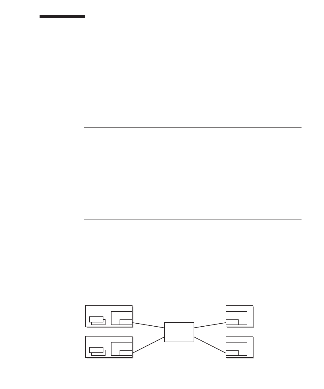
Figure 1-1
An
Example of a Remote Power Management Group of SPARC M12
and SPARC M10
Remote power management
Host Node #0 (Master)
Sub Node
PPAR/Logical domain
Controller BB#1
Slave XSCF
Controller BB#0
Master XSCF
RCIL commands
Host Node #1 I/O Node #0
Controller BB#1
Slave XSCF
Controller BB#0
Master XSCF
Controller
Controller
I/O Node #1
Controller
Controller
IPMI over LAN
Fujitsu SPARC M12 and Fujitsu M10/SPARC M10 RCIL User Guide
・
March 20192
Page 13
1.2 Understanding the Forms of
Connection for Remote Power
Management
Connect through a LAN the host nodes, sub nodes, and I/O nodes that support the
remote power management function for SPARC M12 and SPARC M10.
The following table lists the connection specifications.
Table 1-2
Item Description
Forms of
connection
Transmission
speed
Internet protocol IPv4
DHCP Unsupported
Connection
protocol
*1 The supported IPMI version is IPMI 2.0. In SPARC M12 and SPARC M10, IPMI can be used only by the remote
power management function. IPMI cannot be used by ipmitool or any function other than the remote power
management function for SPARC M12 and SPARC M10.
Power Control Connection Specifications
LAN connection
The connection takes either of the following forms:
- Using XSCF-LAN#0
- Using XSCF-LAN#0 and XSCF-LAN#1
100 Mbps or more
If the remote power management function for SPARC M12 and SPARC
M10 is used, you must set a fixed IP address for a connection target.
IPMI
(*1) over LAN
(Intelligent Platform Management Interface)
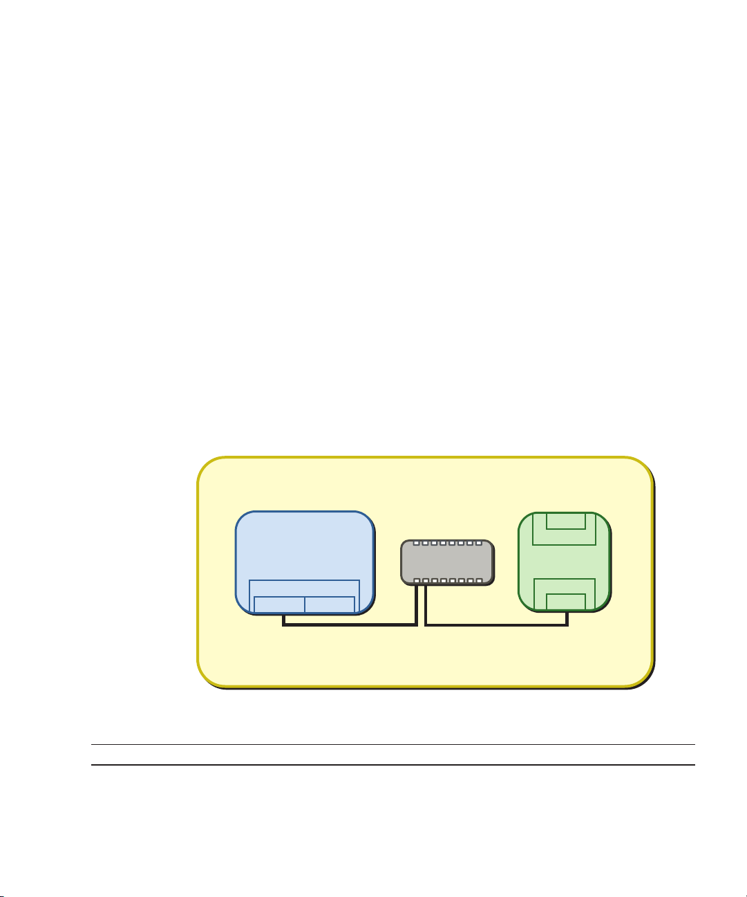
Standard connection for remote power management
Connect through an identical LAN the host nodes, sub nodes, and I/O nodes that are
equipped with a controller that supports the remote power management function for
SPARC M12 and SPARC M10.
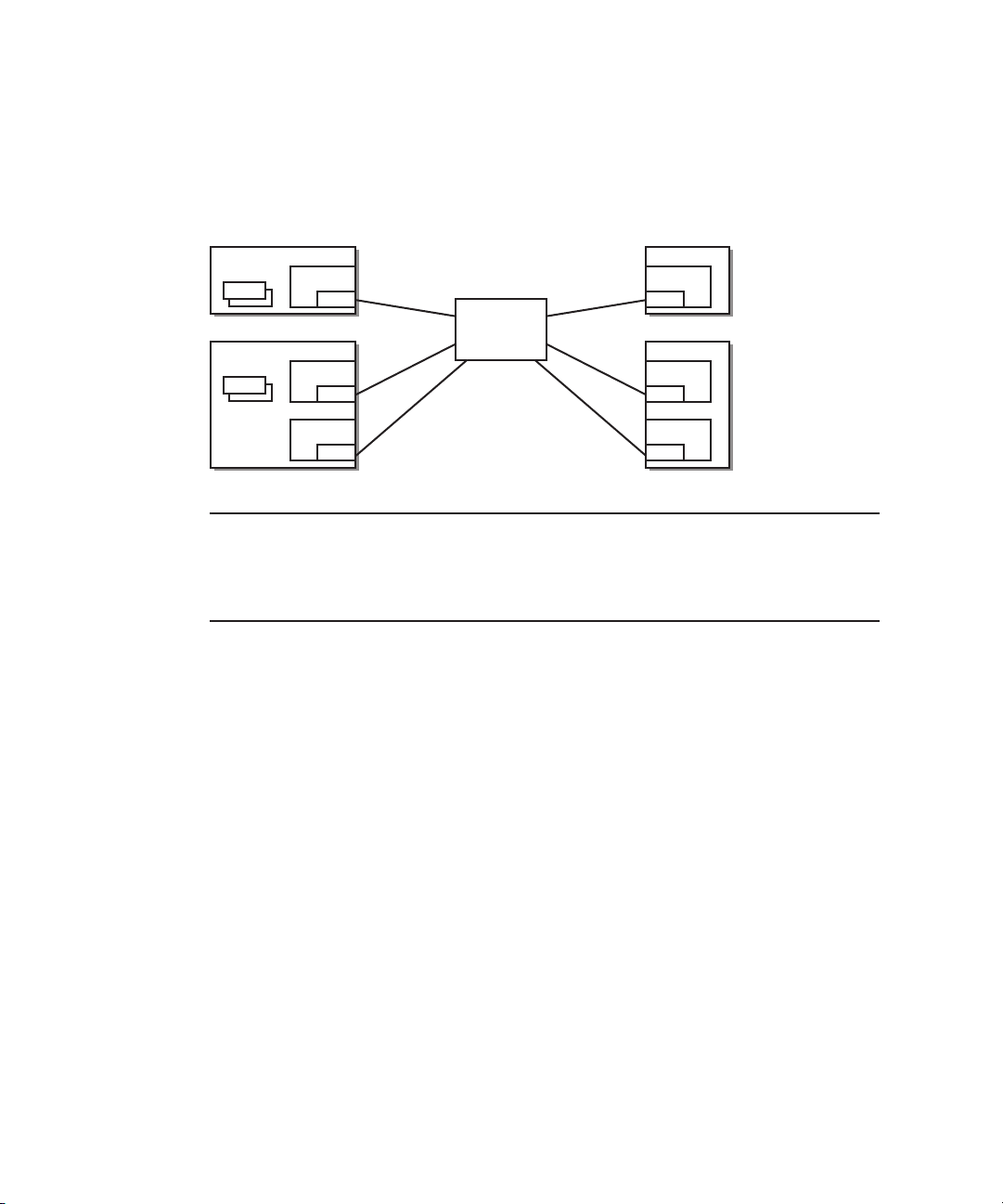
Figure 1-2
Host Node #0
PPAR
Host Node #1
PPAR
Chapter 1 Overview of the Remote Power Management Function of SPARC M12 and SPARC M10 3
Standard Forms of Connection for Remote Power Management
I/O Node #0
Controller
Controller
NIC
NIC
HUB/router
LAN
Controller
NIC
I/O Node #1
Controller
NIC
Page 14
Connection when the controllers are duplicated
If the host node controllers are duplicated, each controller can be connected to the
same LAN. Operation of the remote power management is performed from the
master XSCF.
Figure 1-3
Host Node #0
PPAR
Host Node #1
PPAR
Note -
Forms of Connection for the Remote Power Management when the
Controllers are Duplicated
I/O Node #0
Controller
NIC
Controller 0
NIC
Controller 1
NIC
For the I/O nodes that can be set as a takeover IP address between the controllers, we
HUB/router
LAN
Controller
NIC
I/O Node #1
Controller #0
NIC
Controller #1
NIC
recommend setting a takeover IP address. In such cases, set controllers 0 and 1 to the same IP
address in the management file for configuring a remote power management group.
For details on
specific settings, see "3.1.1 System That is Configured with a Host Node and
an I/O Node."
Connection when paths are duplicated
The paths of the remote power management connection can be duplicated under the
following conditions.
■
Two LAN cards can be mounted on the controllers of all nodes.
■
Two LAN cards can be mounted on the controllers of the host nodes, and I/O
nodes have either of the following configurations.
- The controllers of the I/O nodes are duplicated.
- Two LAN cards can be mounted on the controllers of the I/O nodes.
Fujitsu SPARC M12 and Fujitsu M10/SPARC M10 RCIL User Guide
・
March 20194
Page 15
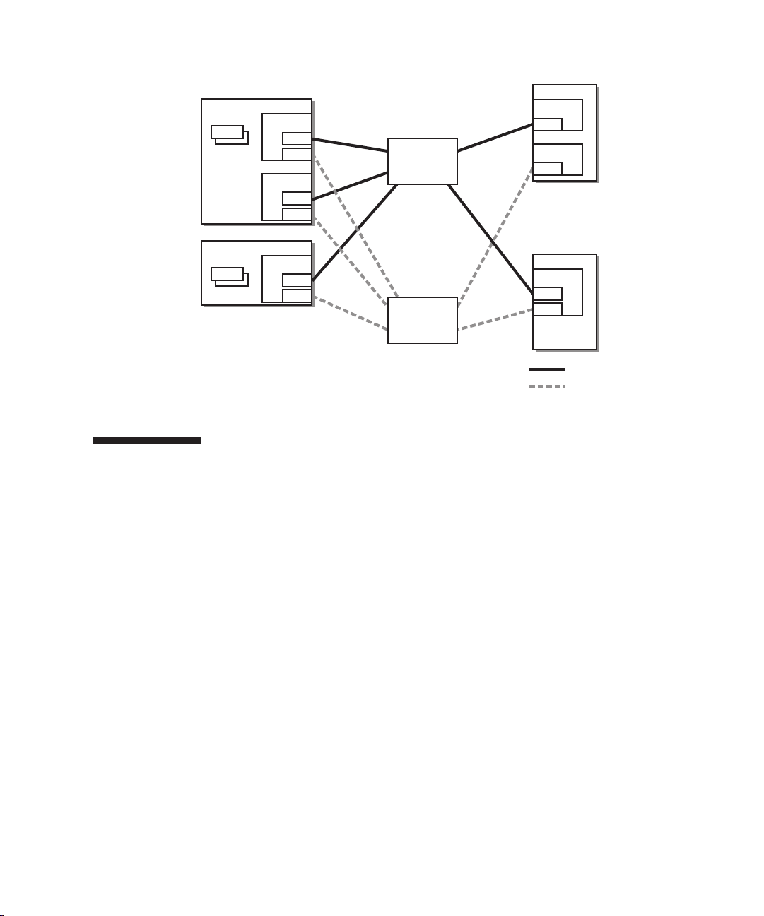
Figure 1-4
Host Node #0
PPAR
Forms of Connection for the Remote Power Management when Paths
are Duplicated
I/O Node #0
Controller #0
NIC #0
NIC #1
Controller #1
NIC #0
NIC #1
HUB/router
LAN #0
Controller #0
NIC
Controller #1
NIC
Host Node #0
PPAR
Controller #0
NIC #0
NIC #1
HUB/router
LAN #1
I/O Node #1
Controller #0
NIC #0
NIC #1
1.3 Remote Power Management
Mechanism
Remote power management for SPARC M12 and SPARC M10 is controlled per
remote power management group.
Of the host nodes in a group, the host nodes with the remote power management
function enabled are targeted for remote power management. The power supply
status of a remote power management group is determined
node status in the group.
■
On state
The power is on to one of the host nodes in the remote power management group.
■
Off state
The power is off to all the host nodes in the remote power management group.
This section describes the mechanism of interlocking when powering on and off,
with the following settings assumed.
depending on the host
LAN #0 system
LAN #1 system
Chapter 1 Overview of the Remote Power Management Function of SPARC M12 and SPARC M10 5
Page 16

Table 1-3
Setting Item Host Node #0 Host Node #1 Host Node #2 I/O Node #0 I/O Node #1
Interlocking
setting
Master node Yes No Yes Setting
Remote Power Management Mechanism (Example)
Disable Enable Enable Setting
disabled
disabled
Setting
disabled
Setting
disabled
Mechanism of interlocking when powering on
If any of the host nodes in a remote power management group is powered on, then
all of the host nodes, subnodes, and I/O nodes in the group are powered on. They are
powered on in the order of host node and I/O node.
Note -
You can set the length of time that the host node waits until I/O node devices are
accessible. For this setting, use the setpowerupdelay command of the XSCF firmware For
details, see "4.2.2 Setting/Checking the Wait Time for Air Conditioning" in the Fujitsu
SPARC M12 and Fujitsu M10/SPARC M10 System
If the length of time that the host node waits is not set, the host node may be unsuccessful in
accessing an I/O node device and fail to start the system.
In addition, replacing an I/O node or changing the settings of an I/O node may change the
time taken until the relevant device becomes accessible. This change in time may prevent the
host node from accessing the device.
When an I/O node has been replaced or the settings of an I/O node have been changed, use
the setpowerupdelay command to set the length of time that the host node
Operation and Administration Guide.
waits, again.
Mechanism of interlocking when powering off
After all the host nodes in a remote power management group are powered off, all
I/O nodes in the group are powered off.
Remote power management using Wake on LAN
Generally, the target nodes of the remote power management function for SPARC
M12 and SPARC M10 are the hosts and I/O devices on which a controller is mounted.
The controller allows IPMI communication even while the power of the hosts and I/O
devices are turned off.
When all of the following
controller are not mounted can also perform power supply interlocking using the
remote power management function for SPARC M12 and SPARC M10.
■
Device conditions
- Wake on LAN is supported.
Power-on is performed with Wake on LAN.
- IPMI communication can be performed.
After power-on using Wake on LAN, IPMI communication through the LAN is
used for performing power-off and obtaining the power state.
Note -
A host node with the Wake on LAN setting cannot be the master node.
Fujitsu SPARC M12 and Fujitsu M10/SPARC M10 RCIL User Guide
conditions are satisfied, those devices on which such a
・
March 20196
Page 17

Note -
Wake on LAN cannot be set for SPARC M12 and SPARC M10. Therefore, Wake on
LAN cannot be used to power on SPARC M12 and SPARC M10.
Note -
The Wake on LAN setting varies depending on the node. See the respective node
manuals.
Interlocking at the failure recovery time
If a node in a remote power management group cannot communicate when
recovered from a failure or other problem, operation is as follows.
■
For an I/O node failure
If the power to the remote power management group is on, the master host node
issues a power-on instruction.
■
For a host node failure
Even if the power of a remote power management group is on, the master host
node does not issue a power-on instruction.
Chapter 1 Overview of the Remote Power Management Function of SPARC M12 and SPARC M10 7
Page 18

Fujitsu SPARC M12 and Fujitsu M10/SPARC M10 RCIL User Guide
・
March 20198
Page 19

Chapter 2
Basic Flow for Configuring Remote
Power Management
This section describes how to configure the remote power management function and
how to use commands.
■
Before Configuring Remote Power Management
■
Steps for Configuring Remote Power Management
2.1 Before Configuring Remote Power Management
Before configuring remote power management, you need to connect the LAN cables,
and make the network settings for the XSCF-LAN and the I/O devices for which
remote power management is to be employed.
2.2 Steps for Configuring Remote Power Management
This section describes the steps for configuring remote power management.
Configure the remote power management function by combining these steps. For an
explanation of the actual configuration process for specific cases, see "Chapter 3
Examples of Remote Power Management Configuration."
2.2.1 Creating a Management File
A management file for configuring remote power management is created in CSV
format for each remote power management group. You can create a management file
at a
storage location accessible by a URL with http, https, ftp, or file scheme.
9
Page 20

The management file script format is as follows.
1,1,0x01,8a041209b35947899e7bfa5d578dbd3f,0x01,0x00,default,,10.24.0.0,0x10,
xx:xx:xx:xx:xx:xx,,,,,,,,,,"4,5,6,7,8,9,10,11,12"
1,2,0x00,8a041209b35947899e7bfa5d578dbd40,0x03,0x00,default,,10.24.0.0,0x10,
xx:xx:xx:xx:xx:xx,,,,,,,,,,
1,3,0x10,8a041209b35947899e7bfa5d578dbd41,0x03,0x00,default,,10.24.0.0,0x10,
xx:xx:xx:xx:xx:xx,,,,,,,,,,
(Omitted)
1,128,0x20,8a041209b35947899e7bfa5d578dbd42,0x03,0x00,default,,10.24.0.0,0x10,
xx:xx:xx:xx:xx:xx,,,,,,,,,,
GroupID, NodeID, NodeType, NodeIdentName, Linkage, Operation, User,
Password, IP0-0, Slave0-0, MAC0-0, IP0-1, Slave0-1, MAC0-1, IP1-0, Slave1-0,
MAC1-0, IP1-1, Slave1-1, MAC1-1, and SubNode are specified on each line in the
order shown.
The following table describes the setting items in detail.
Table 2-1
Item Description
GroupID Group ID of a remote power management group
NodeID Node ID of an interlocking device for power supply
NodeType Node type of an interlocking device for power supply
NodeIdentName Identifier of an interlocking device for power supply
Linkage Value (hexadecimal) representing power-on interlocking
Operation Value representing the power-on method
User IPMI user name
Setting Items of a Management File
Specify an integer value (decimal) from 1 to 32. All group IDs in one
management file must be the same.
Specify an integer value (decimal) from 1 to 128. Each node ID in one
management
Specify any of the following values:
0x00: Host node, 0x01: Mater host node, 0x10: I/O node
0x20: Remote power distribution unit
Specify the system GUID or a unique arbitrary character string.
For the
the example. The value is handled as a hexadecimal number in a
case-insensitive fashion.
For the arbitrary character string, specify a hexadecimal number with up
to 32
Specify any of the following values:
0x00: Disable,
0x03: Enable (On + Off)
Specify either of the following values:
0x00: IPMI, 0x01: WakeOnLAN
Specify nothing, and leave this field blank. If the field is not blank, the
operation cannot be guaranteed.
file must be unique.
system GUID, specify a string of 32 consecutive digits as shown in
digits.
0x01: Enable (On), 0x02: Enable (Off),
Fujitsu SPARC M12 and Fujitsu M10/SPARC M10 RCIL User Guide
・
March 201910
Page 21

Table 2-1
Item Description
Password IPMI password
IPAddress
(IP0-0/IP0-1/IP10/IP1-1)
SlaveAddress
(Slave0-0/
Slave0-1/Slave10/Slave1-1)
MAC Address
(MAC0-0/
MAC0-1/MAC10/MAC1-1)
SubNodeID Character string representing the ID of the controlled subnode
Setting Items of a Management File (continued)
Specify nothing, and leave this field blank.
IP address of the IPMI port of a controller
Specify an IPv4 address value with a character string.
Value (hexadecimal) representing the IPMI slave address of a controller
Specify "0x20".
MAC address of the IPMI port of a controller
Specify
a MAC address value with a character string.
Example: b0:99:28:98:18:2e
A value must be set even though host nodes do not support power-on via
Wake on LAN. In this case, a dummy value like the following may be
used:
Example: 00:00:00:00:00:00
The field is
Delimit the target subnode IDs (in decimal) with a comma (,), and enclose
all of them in double quotation marks (").
A blank field indicates control of the whole node.
a value from 0 to 31 or is left blank.
2.2.2 Enabling/Disabling the IPMI Service Used for the Remote Power Management Function
When the remote power management function is to be used, the IPMI service must
be
enabled.
The IPMI service can be used only by the remote power management function.
Use the setpacketfilters of the XSCF firmware to enable/disable the IPMI service.
XSCF>
To enable the IPMI service, specify the -c ipmi_port enable option.
service, specify the -c ipmi_port disable option.
The default value is disable.
Note -
For XCP 2280 or earlier, the IPMI service has been enabled as a fixed setting and cannot be
disabled.
The settings for the IPMI service are as follows when the firmware is updated from XCP 2280
or
earlier to XCP 2290 or later.
- When the remote power management function is used: Enable
- When the remote power management function is unused: Disable
setpacketfilters -c ipmi_port {enable|disable}
To disable the
The setting for enabling/disabling the IPMI service is supported by XCP 2290 or later.
Chapter 2 Basic Flow for Configuring Remote Power Management 11
Page 22

2.2.3 Checking the Remote Power Management Settings
To check the contents of the remote power management settings, use the
showremotepwrmgmt command of the XSCF firmware.
XSCF>
To check all the remote power management settings, specify -a. To indicate a remote
power management group, specify -G groupid. To indicate a node in a remote power
management group, specify -N gnodeid.
showremotepwrmgmt [-a|-G
groupid
[-N
gnodeid
]]
2.2.4 Initializing the Remote Power Management Settings
To initialize the contents of the remote power management settings, use the
clearremotepwrmgmt command of the XSCF firmware.
]
2.2.5
XSCF>
To initialize the settings of all the remote power management groups, specify -a. To
indicate a remote power management group, specify a group ID with the -G option.
If -a
clearremotepwrmgmt
and -G options
are omitted, then the -a option is used by default.
[-a|
-G
groupid
Enabling/Disabling the Remote Power Management
Function
To enable/disable the remote power management function, use the setremotepwrmgmt
command of the XSCF firmware.
XSCF>
You can enable or disable the remote power management function. To enable the
remote power management function, specify the -c enable option. To disable, specify
the -c disable option.
setremotepwrmgmt -c enable|disable
2.2.6 Setting a Remote Power Management Group
To configure a remote power management group, use the setremotepwrmgmt
command of the XSCF firmware.
Fujitsu SPARC M12 and Fujitsu M10/SPARC M10 RCIL User Guide
・
March 201912
Page 23

XSCF>
You can specify -c config if you configure a remote power management group. For
configuration_file, specify the management file used for the settings.
setremotepwrmgmt -c config
configuration_file
2.2.7 Acquiring the setting information on a remote power management group
To acquire the setting information on a remote power management group, use the
getremotepwrmgmt command of the XSCF firmware.
XSCF>
For groupid, you can specify the ID of a remote power management group whose
setting information is obtained. For configuration_file, specify the name of the
management file for saving the acquired setting
getremotepwrmgmt -G
groupid configuration_file
information.
Chapter 2 Basic Flow for Configuring Remote Power Management 13
Page 24

Fujitsu SPARC M12 and Fujitsu M10/SPARC M10 RCIL User Guide
・
March 201914
Page 25

Chapter 3
Examples of Remote Power
Management Configuration
This section describes how to configure the remote power management in the
following cases.
■
Configuring the Remote Power Management for the First Time
■
Adding or Removing a Node in an Existing Remote Power Management Group
■
Maintaining an I/O Node
3.1 Configuring the Remote Power Management for the First Time
The following shows how to configure the remote power management for the first
time.
Note -
If the existing settings for the remote power management are valid, initialize the
settings.
To create a management file, collect the necessary information on the host nodes, the
IP
and MAC addresses of I/O nodes, etc. in advance (see Table 3-1).
15
Page 26
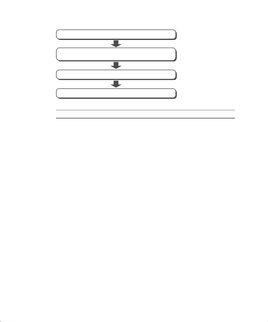
Figure 3-1
Flow of Configuring the Remote Power Management for the First
Time
Create management file
Enable the IPMI service used by the remote power
management function
Set a remote power management group
Enable the remote power management function
Note -
The setting for enabling/disabling the IPMI service is supported by XCP 2290 or later.
In the following sections, how to configure the remote power management is
described by using the system configurations below as examples.
■
System That is Configured with a Host Node and an I/O Node
■
System That is Configured with a Host Node and a Remote Power Distribution
Unit
■
System That is Configured with Multiple Host Nodes and a Remote Power
Distribution Unit
■
System That is Configured with Host Nodes, in Which Physical Partitions (PPARs)
are Specified as Subnodes, and a Remote Power Distribution Unit
■
System in Which Multiple Remote Power Management Groups are Set
3.1.1 System That is Configured with a Host Node and
I/O Node
an
This section describes how to configure the remote power management by using a
system that is configured with one SPARC M10-1 as a host node and one ETERNUS
DX80 S2 as an I/O node as an example.
Collect necessary information for a management file and create the file.
1.
Collect the IP
management will be configured. Based on the collected information, create a
management file in CSV format for each remote power management group. The
line feed code is LF or CR+LF.
ETERNUS DX80 S2 supports multiple controllers. The system can be
by
setting a different or same IP address per controller. We recommend setting
the same IP address. There are restrictions when a different IP address is set per
controller. (See "
Fujitsu SPARC M12 and Fujitsu M10/SPARC M10 RCIL User Guide
address and MAC address of the device where the remote power
operated
Restrictions when a different IP address is set per controller
March 201916
・
.")
Page 27
To operate the system with the same IP address set for multiple controllers, set
the same IP address to IP0-0 and IP1-0 or IP0-1 and IP1-1. For details on how to
check the ETERNUS controller configuration and IP addresses, see the
ETERNUS manuals.
However, in either configuration, IP0-1 cannot be set
Similarly, IP1-1 cannot be set without setting IP1-0. Select IP0-0/IP0-1 or
IP1-0/IP1-1 based on the LAN port of the SPARC M10 system to be connected
and the type of controller used in the ETERNUS. For example, when connecting
to
LAN#0 of the XSCF, set the LAN of CM#0
IP1-0.
to
without setting IP0-0.
IP0-0 and the LAN of CM#1 to
Restrictions when a different IP address is set per controller
"IO Node power resumed" may be registered in the error log when an error
occurs in the network and CM#0 cannot respond.
Furthermore, if the network is unstable, the "IO Node power resumed"
be
registered repeatedly.
error will
The "IO Node power resumed" error usually indicates that an I/O node was
powered on again since being powered off. However, if a different IP address is
set per controller, the "IO Node power resumed" error may be registered even
though no I/O node has been
powered off. This issue is caused by the network.
- Configure the settings as follows when using only ETERNUS DX80 CM#0.
Figure 3-2
System Using Only ETERNUS DX80 CM#0
Remote power management group
SPARC M10-1
XSCF
LAN#0
IP: 10.24.101.1
MAC: b0:99:28:98:18:2e
Table 3-1
Item Setting Value Remarks
GroupID 1
NodeID 1
NodeType 0x01 Master host node
Setting Values of the Management File (SPARC M10-1)
LAN#1
Switching hub
MNT
CM#1
ETERNUS
DX80 S2
CM#0
MNT
IP:10.24.101.2
MAC:00:ff:75:b8:14:bd
CM: Controller module
Chapter 3 Examples of Remote Power Management Configuration 17
Page 28

Table 3-1
Item Setting Value Remarks
NodeIdentName
Setting Values of the Management File (SPARC M10-1) (continued)
0123456789abcdef0000000000000001
Unique ID that consists of a hexadecimal number
with 32 digits, such as System GUID
Linkage 0x01 Interlocking power-on actions
Operation 0x00 IPMI
User Blank
Password Blank
IP0-0 10.24.101.1
Slave0-0 0x20 Fixed value
MAC0-0 b0:99:28:98:18:2e
IP0-1 Blank
Slave0-1 Blank
MAC0-1 Blank
IP1-0 Blank
Slave1-0 Blank
MAC1-0 Blank
IP1-1 Blank
Slave1-1 Blank
MAC1-1 Blank
SubNode Blank
Table 3-2
Item Setting Value Remarks
Setting Values of the Management File (ETERNUS DX80 S2)
GroupID 1
NodeID 2
NodeType 0x10 I/O node
NodeIdentName
0123456789abcdef0000000000000002
Unique ID that consists of a hexadecimal number
with 32 digits, such as System GUID
Linkage 0x03 Interlocking power-on and power-off actions
Operation 0x01 Wake On LAN
User Blank
Password Blank
IP0-0 10.24.101.2
Slave0-0 0x20 Fixed value
MAC0-0 00:ff:75:b8:14:bd
IP0-1 Blank
Fujitsu SPARC M12 and Fujitsu M10/SPARC M10 RCIL User Guide
・
March 201918
Page 29

Table 3-2
Item Setting Value Remarks
Setting Values of the Management File (ETERNUS DX80 S2) (continued)
Slave0-1 Blank
MAC0-1 Blank
IP1-0 Blank
Slave1-0 Blank
MAC1-0 Blank
IP1-1 Blank
Slave1-1 Blank
MAC1-1 Blank
SubNode Blank
The management file is created as follows.
1,1,0x01,0123456789abcdef0000000000000001,0x01,0x00,,,10.24.101.1,
0x20,b0:99:28:98:18:2e,,,,,,,,,,
1,2,0x10,0123456789abcdef0000000000000002,0x03,0x01,,,10.24.101.2,
0x20,00:ff:75:b8:14:bd,,,,,,,,,,
Chapter 3 Examples of Remote Power Management Configuration 19
Page 30

- Configure the settings as follows when operating the system, setting the same
IP
address for multiple controllers using CM#0 and CM#1 of the ETERNUS
DX80. (Recommended)
Figure 3-3
System in Which the Same IP Address is Specified for Multiple
Controllers of the I/O Node
Remote power management group
IP:10.24.101.2
MAC:00:ff:75:b8:14:ae
MNT
CM#1
SPARC M10-1
XSCF
LAN#0
IP: 10.24.101.1
MAC: b0:99:28:98:18:2e
Table 3-3
Item Setting Value Remarks
Setting Values of the Management File (ETERNUS DX80 S2) (*1)
LAN#1
Switching hub
IP:10.24.101.2
MAC:00:ff:75:b8:14:bd
ETERNUS
DX80 S2
CM#0
MNT
CM: Controller module
GroupID 1
NodeID 2
NodeType 0x10 I/O node
NodeIdentName
0123456789abcdef0000000000000002
Unique ID that consists of a hexadecimal number
with 32 digits, such as System GUID
Linkage 0x03 Interlocking power-on and power-off actions
Operation 0x01 Wake On LAN
User Blank
Password Blank
IP0-0 10.24.101.2
Slave0-0 0x20 Fixed value
MAC0-0 00:ff:75:b8:14:bd
IP0-1 Blank
Slave0-1 Blank
MAC0-1 Blank
IP1-0 10.24.101.2
Slave1-0 0x20 Fixed value
Fujitsu SPARC M12 and Fujitsu M10/SPARC M10 RCIL User Guide
・
March 201920
Page 31

Table 3-3
Item Setting Value Remarks
Setting Values of the Management File (ETERNUS DX80 S2) (*1) (continued)
MAC1-0 00:ff:75:b8:14:ae
IP1-1 Blank
Slave1-1 Blank
MAC1-1 Blank
SubNode Blank
*1 A colored line indicates that the setting is different from the original setting.
The management file is created as follows.
1,1,0x01,0123456789abcdef0000000000000001,0x01,0x00,,,10.24.101.1,
0x20,b0:99:28:98:18:2e,,,,,,,,,,
1,2,0x10,0123456789abcdef0000000000000002,0x03,0x01,,,10.24.101.2,
0x20,00:ff:75:b8:14:bd,,,,10.24.101.2,0x20,00:ff:75:b8:14:ae,,,,,
Chapter 3 Examples of Remote Power Management Configuration 21
Page 32

- Configure as follows when operating the system by setting a different IP
address for each controller using CM#0 and CM#1 of the ETERNUS DX80 S2.
(Not recommended)
Figure 3-4
System in Which a Different IP Address are Specified for Multiple
Controllers of I/O Nodes
Remote power management group
IP:10.24.101.3
MAC:00:ff:75:b8:14:ae
MNT
CM#1
SPARC M10-1
XSCF
LAN#0
IP: 10.24.101.1
MAC: b0:99:28:98:18:2e
Table 3-4
Item Setting Value Remarks
Setting Values of the Management File (ETERNUS DX80 S2) (*1)
LAN#1
Switching hub
IP:10.24.101.2
MAC:00:ff:75:b8:14:bd
ETERNUS
DX80 S2
CM#0
MNT
CM: Controller module
GroupID 1
NodeID 2
NodeType 0x10 I/O node
NodeIdentName
0123456789abcdef0000000000000002
Unique ID that consists of a hexadecimal number
with 32 digits, such as System GUID
Linkage 0x03 Interlocking power-on and power-off actions
Operation 0x01 Wake On LAN
User Blank
Password Blank
IP0-0 10.24.101.2
Slave0-0 0x20 Fixed value
MAC0-0 00:ff:75:b8:14:bd
IP0-1 Blank
Slave0-1 Blank
MAC0-1 Blank
IP1-0 10.24.101.3
Fujitsu SPARC M12 and Fujitsu M10/SPARC M10 RCIL User Guide
・
March 201922
Page 33

Table 3-4
Item Setting Value Remarks
Setting Values of the Management File (ETERNUS DX80 S2) (*1) (continued)
Slave1-0 0x20 Fixed value
MAC1-0 00:ff:75:b8:14:ae
IP1-1 Blank
Slave1-1 Blank
MAC1-1 Blank
SubNode Blank
*1 A colored line indicates that the setting is different from the original setting.
The management file is created as follows.
1,1,0x01,0123456789abcdef0000000000000001,0x01,0x00,,,10.24.101.1,
0x20,b0:99:28:98:18:2e,,,,,,,,,,
1,2,0x10,0123456789abcdef0000000000000002,0x03,0x01,,,10.24.101.2,
0x20,00:ff:75:b8:14:bd,,,,10.24.101.3,0x20,00:ff:75:b8:14:ae,,,,,
Chapter 3 Examples of Remote Power Management Configuration 23
Page 34

- Configure as follows when using XSCF-LAN#0 and XSCF-LAN#1 in the 4BB
configuration of the SPARC M10-4S.
XSCF-LAN#0 and XSCF-LAN#1 are connected to switches. Though the
ETERNUS is connected with the same subnet as LAN#0, it is connected to
LAN#1 of the SPARC M10-4S via a router.
Figure 3-5
BB#00
LAN#0:10.24.101.1
MAC: b0:99:28:98:38:a2
LAN#1:10.24.102.1
MAC: b0:99:28:98:38:a3
BB#01
LAN#0:10.24.101.3
MAC: b0:99:28:98:38:b2
LAN#1:10.24.102.3
MAC: b0:99:28:98:38:b3
System in
are Used
SPARC M10-4S
(BB#00)
XSCF
LAN#0
LAN#1
Which XSCF-LAN#0 and XSCF-LAN#1 of SPARC M10-4S
Remote power management group
SPARC M10-4S
LAN#0
Router
(BB#01)
XSCF
LAN#1
Switching
hub
SPARC M10-4S
(BB#02)
XSCF
IP:10.24.101.2
MAC:00:ff:75:b8:14:ae
Switching
hub
IP:10.24.101.2
MAC:00:ff:75:b8:14:bd
CM: Controller module
SPARC M10-4S
(BB#03)
XSCF
MNT
CM#1
ETERNUS
DX80 S2
CM#0
MNT
Table 3-5
Item Setting Value Remarks
Setting Values of the Management File (SPARC M10-4S)
GroupID 1
NodeID 1
NodeType 0x01 Master host node
NodeIdentName
0123456789abcdef0000000000000001
Unique ID that consists of a hexadecimal number
with 32 digits, such as System GUID
Linkage 0x01 Interlocking power-on actions
Operation 0x00 IPMI
User Blank
Password Blank
IP0-0 10.24.101.1
Slave0-0 0x20 Fixed value
Fujitsu SPARC M12 and Fujitsu M10/SPARC M10 RCIL User Guide
・
March 201924
Page 35

Table 3-5
Item Setting Value Remarks
Setting Values of the Management File (SPARC M10-4S) (continued)
MAC0-0 b0:99:28:98:38:a2
IP0-1 10.24.102.1
Slave0-1 0x20 Fixed value
MAC0-1 b0:99:28:98:38:a3
IP1-0 10.24.101.3
Slave1-0 0x20 Fixed value
MAC1-0 b0:99:28:98:38:b2
IP1-1 10.24.102.3
Slave1-1 0x20 Fixed value
MAC1-1 b0:99:28:98:38:b3
SubNode Blank
Table 3-6
Item Setting Value Remarks
Setting Values of the Management File (ETERNUS DX80 S2) (*1)
GroupID 1
NodeID 2
NodeType 0x10 I/O node
NodeIdentName
0123456789abcdef0000000000000002
Unique ID that consists of a hexadecimal number
with 32 digits, such as System GUID
Linkage 0x03 Interlocking power-on and power-off actions
Operation 0x01 Wake On LAN
User Blank
Password Blank
IP0-0 10.24.101.2
Slave0-0 0x20 Fixed value
MAC0-0 00:ff:75:b8:14:bd
IP0-1 Blank
Slave0-1 Blank
MAC0-1 Blank
IP1-0 10.24.101.2
Slave1-0 0x20 Fixed value
MAC1-0 00:ff:75:b8:14:ae
IP1-1 Blank
Slave1-1 Blank
MAC1-1 Blank
Chapter 3 Examples of Remote Power Management Configuration 25
Page 36

Table 3-6
Item Setting Value Remarks
SubNode Blank
*1 A colored line indicates that the setting is different from the original setting.
Setting Values of the Management File (ETERNUS DX80 S2) (*1) (continued)
The management file is created as follows.
1,1,0x01,0123456789abcdef0000000000000001,0x01,0x00,,,10.24.101.1,
0x20,b0:99:28:98:38:a2,10.24.102.1,0x20,b0:99:28:98:38:a3,10.24.101.3,0x20,b0:
99:28:98:38:b2,10.24.102.3,0x20,b0:99:28:98:38:b3,
1,2,0x10,0123456789abcdef0000000000000002,0x03,0x01,,,10.24.101.2,
0x20,00:ff:75:b8:14:bd,,,,10.24.101.2,0x20,00:ff:75:b8:14:ae,,,,,
Enable the IPMI service that is to be used for the remote power management
2.
function.
Execute it by logging into the XSCF shell of all the host nodes and master host
nodes where the remote power management is configured.
XSCF>
3.
XSCF>
Remote power management group is not configured.
XSCF>
All remote power management group informations are cleared.Continue? [y|n]:
clearremotepwrmgmt -a
setpacketfilters -c ipmi_port enable
Configure a remote power management
file.
Execute the showremotepwrmgmt command to confirm that the remote
a.
power management is not configured.
Check the above by logging into the XSCF shell of all the host nodes and
master host nodes where the remote power management is configured. When
configuring the remote power
assumed that the remote power management is not set.
showremotepwrmgmt -a
If
the existing settings for the remote power management are valid, initialize
the settings according to the following process.
Execute the setremotepwrmgmt command to set a remote power
b.
management group.
Execute this step
remote power management group.
Specify the management file created in step 1 and configure a remote power
management group.
Execute the following steps to download the management file of the remote
by logging into the XSCF shell of the master host node in the
management for the first time, it is normally
group using the created management
y
Fujitsu SPARC M12 and Fujitsu M10/SPARC M10 RCIL User Guide
・
March 201926
Page 37

power management group to a USB memory stick.
Insert a USB memory stick into the USB port, on which "MAINTENANCE
1)
ONLY" is printed, on the back panel of the XSCF unit.
The USB memory stick must be in FAT32 format.
The management file can be downloaded by specifying the
stick, and the http, https, or ftp server.
Execute the setremotepwrmgmt command to set a remote power
2)
management group
If
the settings of the downloaded management file are correct, enter "y" for
"Continue? [y|n]:" to apply them.
.
USB memory
XSCF>
Mounted USB device
Download successful: 29184Byte at 1016.857KB/s
Checking file...
The following Remote Power Management Group setting will be applied:
GroupID :01
NodeID NodeType
Operation
------ ----------- -------------------------------- ----------------------
001
002
WakeUpOnLAN
------ ----------- -------------------------------- ----------------------
Continue? [y|n]:
The command completed successfully.
XSCF>
setremotepwrmgmt -c config file:///media/usb_msd/path/rpmgroup-1.conf
-----------
Master HOST 0123456789abcdef00000000 00000001 Enable(Power-On Link) IPMI
I/O
-----------
NodeIdentName
0123456789abcdef0000000000000002 Enable
y
Execute the setremotepwrmgmt command to enable the remote power
4.
management
function.
PowerLinkage
Execute this step for all host nodes and master host nodes where the remote
power management is set.
XSCF>
Remote power management is enabled. Continue? [y|n]:
The command completed successfully.
setremotepwrmgmt -c enable
y
Current setting details can be checked with the showremotepwrmgmt command.
XSCF>
[Remote Power Management Group#01 Information]
Remote Power Management Status
NodeID NodeType
showremotepwrmgmt
Operation
NodeIdentName
:[Enable]
Chapter 3 Examples of Remote Power Management Configuration 27
Power PowerLinkage
Page 38

------ ----------- -------------------------------- -----
---------------------- ----------001
Link) IPMI
002
------ ----------- -------------------------------- -----
---------------------- -----------
Master HOST 0123456789abcdef0000000000000001 OFF
I/O
WakeUpOnLAN
0123456789abcdef0000000000000002 OFF
Enable(Power-On
Enable
3.1.2 System That is Configured with a Host Node and a Remote Power Distribution Unit
This section describes how to configure the remote power management by using a
system that is configured with one SPARC M10-4 and one remote power distribution
unit as an example. The basic setting process is the same as written in "3.1.1 System
That is Configured with a Host Node and
Collect necessary information for a management file and create the file.
1.
Collect the IP address and MAC address of the device where the remote power
management will be configured. Based on the collected information, create a
management file in CSV format for each remote power management group. The
line feed code is LF or CR+LF.
The remote power distribution unit supports the remote power management
using IPMI. By connecting to an I/O device that does not support the remote
power management using the WAKE on LAN through the IPMI, the power-on
and power-off actions between SPARC M12 or SPARC
be
interlocked.
When connecting to an I/O device with multiple controllers, redundancy can be
increased by connecting a remote power distribution unit to each controller. In
this case, when setting the management file of a remote power management
group, set multiple remote power distribution units as
Up to eight I/O devices can be connected to one remote power distribution unit.
When setting a remote power distribution unit to a remote power management
group, set them as one I/O node in the management file regardless of how many
I/O devices are connected to the remote
Set "0x00 (IPMI)" for the Operation setting of the remote power distribution unit.
At least one master host node must be configured. Set "0x00: Disable" or "0x01:
Enable (On)" for the Linkage setting of a host node. The operation does not
change if "0x00: Disable," "0x01: Enable (On),"
Enable (On + 0ff)" is set.
In the following, how to configure the remote power management is described
based on the configuration below.
- Use only XSCF-LAN#0 of SPARC M10-4
- Use the system by connecting an I/O device to a remote power distribution
unit
an I/O Node."
M10 and the device can
one I/O node.
power distribution unit.
"0x02: Enable (Off)," or "0x03:
Fujitsu SPARC M12 and Fujitsu M10/SPARC M10 RCIL User Guide
・
March 201928
Page 39

- Interlock the power-on and power-off actions of a remote power distribution
unit
- Configure the settings as follows when using one I/O device connected to a
remote power distribution unit.
Figure 3-6
System Using One I/O Device Connected to a Remote Power
Distribution Unit
Remote power management group
SPARC M10-4
XSCF
LAN#0
IP:10.24.101.1 IP:10.24.101.2
MAC: b0:99:28:98:18:2e MAC: c0:ff:75:b8:14:c8
Table 3-7
Item Setting Value Remarks
Setting Values of the Management File (SPARC M10-4)
LAN#1
Switching
hub
Remote power
distribution unit
LAN#0
GroupID 1
NodeID 1
NodeType 0x01 Master host node
NodeIdentName
0123456789abcdef0000000000000001
Unique ID that consists of a hexadecimal number
with 32 digits, such as System GUID
Linkage 0x01 Interlocking power-on actions
Operation 0x00 IPMI
User Blank
Password Blank
IP0-0 10.24.101.1
Slave0-0 0x20 Fixed value
MAC0-0 b0:99:28:98:18:2e
IP0-1 Blank
Slave0-1 Blank
MAC0-1 Blank
I/O device
Chapter 3 Examples of Remote Power Management Configuration 29
Page 40

Table 3-7
Item Setting Value Remarks
Setting Values of the Management File (SPARC M10-4) (continued)
IP1-0 Blank
Slave1-0 Blank
MAC1-0 Blank
IP1-1 Blank
Slave1-1 Blank
MAC1-1 Blank
SubNode Blank
Table 3-8
Item Setting Value Remarks
Setting Values of the Management File (Remote Power Distribution Unit)
GroupID 1
NodeID 2
NodeType 0x20 Remote power distribution unit
NodeIdentName
0123456789abcdef0000000000000002
Unique ID that consists of a hexadecimal number
with 32 digits, such as System GUID
Linkage 0x03 Interlocking power-on and power-off actions
Operation 0x00 IPMI
User Blank
Password Blank
IP0-0 10.24.101.2
Slave0-0 0x20 Fixed value
MAC0-0 c0:ff:75:b8:14:c8
IP0-1 Blank
Slave0-1 Blank
MAC0-1 Blank
IP1-0 Blank
Slave1-0 Blank
MAC1-0 Blank
IP1-1 Blank
Slave1-1 Blank
MAC1-1 Blank
SubNode Blank
The management file is created as follows.
Fujitsu SPARC M12 and Fujitsu M10/SPARC M10 RCIL User Guide
・
March 201930
Page 41

1,1,0x01,0123456789abcdef0000000000000001,0x01,0x00,,,10.24.101.1,
0x20,b0:99:28:98:18:2e,,,,,,,,,,
1,2,0x20,0123456789abcdef0000000000000002,0x03,0x00,,,10.24.101.2,
0x20,c0:ff:75:b8:14:c8,,,,,,,,,,
- Even when multiple I/O devices are connected to a remote power distribution
unit, configure the settings for remote power management as written in "3.1.1
System That is Configured with a Host Node and an I/O Node."
Figure 3-7
System in Which Multiple I/O Devices are Connected to a Remote
Power Distribution Unit
Remote power management group
I/O device
SPARC M10-4
XSCF
LAN#0
IP:10.24.101.1 IP:10.24.101.2
MAC: b0:99:28:98:18:2e
LAN#1
Switching
hub
Remote power
distribution unit
LAN#0
MAC: c0:ff:75:b8:14:c8
I/O device
- Set as follows when the multiple controllers of an I/O device in the system each
connect to a remote power distribution unit.
Chapter 3 Examples of Remote Power Management Configuration 31
Page 42

Figure 3-8
System in Which the Multiple Controllers of an I/O Device Each
Connect to a Remote Power Distribution Unit
Remote power management group
Remote power
distribution unit
LAN#0
IP:10.24.101.3
MAC: c0:ff:75:b8:14:d8
Switching
SPARC M10-4
XSCF
LAN#0
IP:10.24.101.1 IP:10.24.101.2
MAC: b0:99:28:98:18:2e
Note -
If a model that is older than ETERNUS DXxx S2 is used with the firmware that was
LAN#1
hub
MAC: c0:ff:75:b8:14:c8
Remote power
distribution unit
LAN#0
Remote power
management unit
CM#1
ETERNUS DX80 S2
CM#0
Remote power
management unit
CM: Controller module
updated earlier than December 2012, an interlocking unit for power supply needs to be set
between the ETERNUS and a remote power distribution unit.
Table 3-9
Item Setting Value Remarks
Setting Values of the Management File (Remote Power Distribution Unit That is Connected to
CM#0)
GroupID 1
NodeID 2
NodeType 0x20 Remote power distribution unit
NodeIdentName
0123456789abcdef0000000000000002
Unique ID that consists of a hexadecimal number
with 32 digits, such as System GUID
Linkage 0x03 Interlocking power-on and power-off actions
Operation 0x00 IPMI
User Blank
Password Blank
IP0-0 10.24.101.2
Slave0-0 0x20 Fixed value
MAC0-0 c0:ff:75:b8:14:c8
IP0-1 Blank
Slave0-1 Blank
Fujitsu SPARC M12 and Fujitsu M10/SPARC M10 RCIL User Guide
・
March 201932
Page 43

Table 3-9
Item Setting Value Remarks
Setting Values of the Management File (Remote Power Distribution Unit That is Connected to
CM#0) (continued)
MAC0-1 Blank
IP1-0 Blank
Slave1-0 Blank Fixed value
MAC1-0 Blank
IP1-1 Blank
Slave1-1 Blank
MAC1-1 Blank
SubNode Blank
Table 3-10
Item Setting Value Remarks
Setting Values of the Management File (Remote Power Distribution Unit That is Connected to
CM#1)
GroupID 1
NodeID 3
NodeType 0x20 Remote power distribution unit
NodeIdentName
0123456789abcdef0000000000000003
Unique ID that consists of a hexadecimal number
with 32 digits, such as System GUID
Linkage 0x03 Interlocking power-on and power-off actions
Operation 0x00 IPMI
User Blank
Password Blank
IP0-0 10.24.101.3
Slave0-0 0x20 Fixed value
MAC0-0 c0:ff:75:b8:14:d8
IP0-1 Blank
Slave0-1 Blank
MAC0-1 Blank
IP1-0 Blank
Slave1-0 Blank Fixed value
MAC1-0 Blank
IP1-1 Blank
Slave1-1 Blank
MAC1-1 Blank
SubNode Blank
Chapter 3 Examples of Remote Power Management Configuration 33
Page 44

The management file is created as follows.
1,1,0x01,0123456789abcdef0000000000000001,0x01,0x00,,,10.24.101.1,
0x20,b0:99:28:98:18:2e,,,,,,,,,,
1,2,0x20,0123456789abcdef0000000000000002,0x03,0x00,,,10.24.101.2,
0x20,c0:ff:75:b8:14:c8,,,,,,,,,,
1,3,0x20,0123456789abcdef0000000000000003,0x03,0x00,,,10.24.101.3,
0x20,c0:ff:75:b8:14:d8,,,,,,,,,,
Enable the IPMI service that is to be used for the remote power management
2.
function.
Execute it by logging into the XSCF shell of all the host nodes and master host
nodes where the remote power management is configured.
XSCF>
3.
XSCF>
Remote power management group is not configured.
XSCF>
All remote power management group informations are cleared.Continue? [y|n]:
clearremotepwrmgmt -a
setpacketfilters -c ipmi_port enable
Configure a remote power management
file.
Execute the showremotepwrmgmt command to confirm that the remote
a.
power management is not configured.
Check the above by logging into the XSCF shell of all the host nodes and
master host nodes where the remote power management is configured. When
configuring the remote power
assumed that the remote power management is not set.
In
the following example, the remote power management is not set.
showremotepwrmgmt -a
If
the existing settings for the remote power management are valid, initialize
the settings according to the following process.
Execute the setremotepwrmgmt
b.
management group.
Execute this step by logging into the XSCF shell of the master host node in the
remote power management group.
Specify the management file created in step 1 and configure a remote power
management group.
Execute the following steps to download the management
power management group to a USB memory stick.
Insert a USB memory stick into the USB port, on which "MAINTENANCE
1)
ONLY" is printed, on the back panel of the XSCF unit.
management for the first time, it is normally
group using the created management
command to set a remote power
file of the remote
y
Fujitsu SPARC M12 and Fujitsu M10/SPARC M10 RCIL User Guide
・
March 201934
Page 45

The USB memory stick must be in FAT32 format.
The management file can be downloaded by specifying the USB memory
stick, and the http, https, or ftp server.
Execute the setremotepwrmgmt command to set a remote power
2)
management group
If
the settings of the downloaded management file are correct,
"Continue? [y|n]:" to apply them.
.
enter "y" for
XSCF>
Mounted USB device
Download successful: 29184Byte at 1016.857KB/s
Checking file...
The following Remote Power Management Group setting will be applied:
GroupID :01
NodeID NodeType
Operation
------ ----------- -------------------------------- ----------------------
001
002
003
------ ----------- -------------------------------- ----------------------
Continue? [y|n]:
The command completed successfully.
XSCF>
setremotepwrmgmt -c config file:///media/usb_msd/path/rpmgroup-1.conf
-----------
Master HOST 0123456789abcdef00000000 00000001 Enable(Power-On Link) IPMI
PwrLinkBox 0123456789abcdef00000000 00000002 Enable
PwrLinkBox 0123456789abcdef00000000 00000003 Enable
-----------
NodeIdentName
y
Execute the setremotepwrmgmt command to enable the remote power
4.
management function.
PowerLinkage
Execute this step for all host nodes and master host nodes where the remote
power management is set.
XSCF>
Remote power management is enabled. Continue? [y|n]:
The command completed successfully.
setremotepwrmgmt -c enable
y
IPMI
IPMI
Current setting details can be checked with the showremotepwrmgmt command.
XSCF>
[Remote Power Management Group#01 Information]
Remote Power Management Status
NodeID NodeType
------ ----------- -------------------------------- -----
001
Link) IPMI
showremotepwrmgmt
NodeIdentName
Operation
---------------------- ----------Master HOST 0123456789abcdef0000000000000001 OFF
Chapter 3 Examples of Remote Power Management Configuration 35
:[Enable]
Power PowerLinkage
Enable(Power-On
Page 46

002
003
------ ----------- -------------------------------- -----
---------------------- -----------
PwrLinkBox 0123456789abcdef0000000000000002 OFF
IPMI
PwrLinkBox 0123456789abcdef0000000000000003 OFF
IPMI
Enable
Enable
3.1.3 System That is Configured with Multiple Host Nodes and a Remote Power Distribution Unit
This section describes how to configure the remote power management by using a
system that is configured with four SPARC M10-4 systems and a remote power
distribution unit.
The basic process is the same as written in "3.1.1 System That is Configured with a
Host Node and an I/O Node."
Collect necessary information for a management file and create the file.
1.
Collect the IP address and MAC address of the device where the remote power
management will be configured. Based on the collected information, create a
management file in CSV format for each remote power management group. The
line feed code
When connecting multiple host nodes, up to two master host nodes can be set.
This helps to increase redundancy.
If "Off" is specified to the Linkage setting between a host node and master node,
the power-off actions are not interlocked.
To enable the interlocking between the power-on actions
"0x01: Enable (On)" to the Linkage setting. The operation does not change if
"0x03: Enable (On + Off)" is set.
To disable the interlocking between power on actions in the SPARC M10
systems, set "0x00: Disable" to the Linkage setting. The operation does not
change if
In the following, how to configure the remote power management is described
based on the configuration below.
- Use only XSCF-LAN#0 of SPARC M10-4
- Set the first and second SPARC M10-4 systems as master host nodes
- Use one I/O device by connecting it to a remote
device can be shared by the connected SPARC M10-4 systems.
- Interlock between power-on and power-off actions (only interlocking between
power-on actions can be enabled for the host nodes)
is LF or CR+LF.
"0x02: Enable (Off)" is set.
of the host nodes, set
power distribution unitThe I/O
Fujitsu SPARC M12 and Fujitsu M10/SPARC M10 RCIL User Guide
・
March 201936
Page 47

Figure 3-9
System That is Configured with Multiple Host Nodes and a Remote
Power Distribution Unit
Remote power management group
Master host node
SPARC M10-4
(Third system)
XSCF
LAN#0
IP:10.24.101.3
MAC: b0:99:28:98:38:4c
SPARC M10-4
(Fourth system)
LAN#0
IP:10.24.101.4
MAC: b0:99:28:98:38:4d
Table 3-11
Item Setting Value Remarks
Setting Values of the Management File (SPARC M10-4 (First))
LAN#1
XSCF
LAN#1
(Second system)
LAN#0
Switching
hub
SPARC M10-4
XSCF
LAN#1
IP:10.24.101.2
MAC: b0:99:28:98:38:4b
Remote power
distribution unit
IP:10.24.101.5
MAC: c0:ff:75:b8:14:c8
LAN#0
GroupID 1
NodeID 1
NodeType 0x01 Master host node
NodeIdentName
0123456789abcdef0000000000000001
Unique ID that consists of a hexadecimal number
with 32 digits, such as System GUID
Linkage 0x01 Interlocking power-on actions
Operation 0x00 IPMI
User Blank
Password Blank
IP0-0 10.24.101.1
Slave0-0 0x20 Fixed value
MAC0-0 b0:99:28:98:38:4a
IP0-1 Blank
Slave0-1 Blank
MAC0-1 Blank
IP1-0 Blank
SPARC M10-4
(Original system)
XSCF
LAN#0
LAN#1
IP:10.24.101.1
MAC: b0:99:28:98:38:4a
I/O device
Chapter 3 Examples of Remote Power Management Configuration 37
Page 48

Table 3-11
Item Setting Value Remarks
Setting Values of the Management File (SPARC M10-4 (First)) (continued)
Slave1-0 Blank
MAC1-0 Blank
IP1-1 Blank
Slave1-1 Blank
MAC1-1 Blank
SubNode Blank
Table 3-12
Item Setting Value Remarks
Setting Values of the Management File (SPARC M10-4 (Second))
GroupID 1
NodeID 2
NodeType 0x01 Master host node
NodeIdentName
0123456789abcdef0000000000000002
Unique ID that consists of a hexadecimal number
with 32 digits, such as System GUID
Linkage 0x01 Interlocking power-on actions
Operation 0x00 IPMI
User Blank
Password Blank
IP0-0 10.24.101.2
Slave0-0 0x20 Fixed value
MAC0-0 b0:99:28:98:38:4b
IP0-1 Blank
Slave0-1 Blank
MAC0-1 Blank
IP1-0 Blank
Slave1-0 Blank
MAC1-0 Blank
IP1-1 Blank
Slave1-1 Blank
MAC1-1 Blank
SubNode Blank
Table 3-13
Item Setting Value Remarks
Setting Values of the Management File (SPARC M10-4 (Third))
GroupID 1
Fujitsu SPARC M12 and Fujitsu M10/SPARC M10 RCIL User Guide
・
March 201938
Page 49

Table 3-13
Item Setting Value Remarks
Setting Values of the Management File (SPARC M10-4 (Third)) (continued)
NodeID 3
NodeType 0x00 Host node
NodeIdentName
0123456789abcdef0000000000000003
Unique ID that consists of a hexadecimal number
with 32 digits, such as System GUID
Linkage 0x01 Interlocking power-on actions
Operation 0x00 IPMI
User Blank
Password Blank
IP0-0 10.24.101.3
Slave0-0 0x20 Fixed value
MAC0-0 b0:99:28:98:38:4c
IP0-1 Blank
Slave0-1 Blank
MAC0-1 Blank
IP1-0 Blank
Slave1-0 Blank
MAC1-0 Blank
IP1-1 Blank
Slave1-1 Blank
MAC1-1 Blank
SubNode Blank
Table 3-14
Item Setting Value Remarks
Setting Values of the Management File (SPARC M10-4 (Fourth))
GroupID 1
NodeID 4
NodeType 0x00 Host node
NodeIdentName
0123456789abcdef0000000000000004
Unique ID that consists of a hexadecimal number
with 32 digits, such as System GUID
Linkage 0x01 Interlocking power-on actions
Operation 0x00 IPMI
User Blank
Password Blank
IP0-0 10.24.101.4
Slave0-0 0x20 Fixed value
Chapter 3 Examples of Remote Power Management Configuration 39
Page 50

Table 3-14
Item Setting Value Remarks
Setting Values of the Management File (SPARC M10-4 (Fourth)) (continued)
MAC0-0 b0:99:28:98:38:4d
IP0-1 Blank
Slave0-1 Blank
MAC0-1 Blank
IP1-0 Blank
Slave1-0 Blank
MAC1-0 Blank
IP1-1 Blank
Slave1-1 Blank
MAC1-1 Blank
SubNode Blank
Table 3-15
Item Setting Value Remarks
Setting Values of the Management File (Remote Power Distribution Unit)
GroupID 1
NodeID 5
NodeType 0x20 Remote power distribution unit
NodeIdentName
0123456789abcdef0000000000000005
Unique ID that consists of a hexadecimal number
with 32 digits, such as System GUID
Linkage 0x03 Interlocking power-on and power-off actions
Operation 0x00 IPMI
User Blank
Password Blank
IP0-0 10.24.101.5
Slave0-0 0x20 Fixed value
MAC0-0 c0:ff:75:b8:14:c8
IP0-1 Blank
Slave0-1 Blank
MAC0-1 Blank
IP1-0 Blank
Slave1-0 Blank
MAC1-0 Blank
IP1-1 Blank
Slave1-1 Blank
MAC1-1 Blank
Fujitsu SPARC M12 and Fujitsu M10/SPARC M10 RCIL User Guide
・
March 201940
Page 51

Table 3-15
Item Setting Value Remarks
SubNode Blank
Setting Values of the Management File (Remote Power Distribution Unit) (continued)
The management file is created as follows.
1,1,0x01,0123456789abcdef0000000000000001,0x01,0x00,,,10.24.101.1,
0x20,b0:99:28:98:38:4a,,,,,,,,,,
1,2,0x01,0123456789abcdef0000000000000002,0x01,0x00,,,10.24.101.2,
0x20,b0:99:28:98:38:4b,,,,,,,,,,
1,3,0x00,0123456789abcdef0000000000000003,0x01,0x00,,,10.24.101.3,
0x20,b0:99:28:98:38:4c,,,,,,,,,,
1,4,0x00,0123456789abcdef0000000000000004,0x01,0x00,,,10.24.101.4,
0x20,b0:99:28:98:38:4d,,,,,,,,,,
1,5,0x20,0123456789abcdef0000000000000005,0x03,0x00,,,10.24.101.5,
0x20,c0:ff:75:b8:14:c8,,,,,,,,,,
Enable the IPMI service that is to be used for the remote power management
2.
function.
Execute it by logging into the XSCF shell of all the host nodes and master host
nodes where the remote power management is configured.
XSCF>
3.
XSCF>
Remote power management group is not configured.
XSCF>
All remote power management group informations are cleared.Continue? [y|n]:
clearremotepwrmgmt -a
setpacketfilters -c ipmi_port enable
Configure a remote power management
file.
Execute the showremotepwrmgmt command to confirm that the remote
a.
power management is not configured.
Check the above by logging into the XSCF shell of all the host nodes and
master host nodes where the remote power management is configured. When
configuring the remote power
assumed that the remote power management is not set.
In
the following example, the remote power management is not set.
showremotepwrmgmt -a
If
the existing settings for the remote power management are valid, initialize
the settings according to the following process.
Execute the setremotepwrmgmt
b.
management group.
Execute this step by logging into the XSCF shell of either a host node or
management for the first time, it is normally
group using the created management
command to set a remote power
y
Chapter 3 Examples of Remote Power Management Configuration 41
Page 52

master host node in the remote power management group.
Download the management file created in step 1 with the setremotepwrmgmt
command of the XSCF firmware.
Execute the following steps to download the management file of the remote
power management group to a USB memory stick.
Insert a USB memory
1)
ONLY" is printed, on the back panel of the XSCF unit.
The USB memory stick must be in FAT32 format.
The management file can be downloaded by specifying the USB memory
stick, and the http, https, or ftp server.
Execute the setremotepwrmgmt
2)
management group
If
the settings of the downloaded management file are correct, enter "y" for
"Continue? [y|n]:" to apply them.
stick into the USB port, on which "MAINTENANCE
command to set a remote power
.
XSCF>
Mounted USB device
Download successful: 29184Byte at 1016.857KB/s
Checking file...
The following Remote Power Management Group setting will be applied:
GroupID :01
NodeID NodeType
Operation
------ ----------- -------------------------------- ----------------------
001
002
003
004
005
------ ----------- -------------------------------- ----------------------
Continue? [y|n]:
The command completed successfully.
XSCF>
setremotepwrmgmt -c config file:///media/usb_msd/path/rpmgroup-1.conf
-----------
Master HOST 0123456789abcdef00000000 00000001 Enable(Power-On Link) IPMI
Master HOST 0123456789abcdef00000000 00000002 Enable(Power-On Link) IPMI
HOST
HOST
PwrLinkBox 0123456789abcdef00000000 00000005 Enable
-----------
NodeIdentName
4.
0123456789abcdef00000000 00000003 Enable(Power-On Link) IPMI
0123456789abcdef00000000 00000004 Enable(Power-On Link) IPMI
y
Execute the setremotepwrmgmt command to enable the remote power
management function.
PowerLinkage
Execute this step for all host nodes and master host nodes where the
power management is set.
remote
IPMI
XSCF>
Remote power management is enabled. Continue? [y|n]:
The command completed successfully.
setremotepwrmgmt -c enable
Current setting details can be checked with the showremotepwrmgmt command.
Fujitsu SPARC M12 and Fujitsu M10/SPARC M10 RCIL User Guide
・
March 201942
y
Page 53

XSCF>
[Remote Power Management Group#01 Information]
Remote Power Management Status
NodeID NodeType
------ ----------- -------------------------------- -----
001
Link) IPMI
002
Link) IPMI
003
Link) IPMI
004
Link)
005
------ ----------- -------------------------------- -----
showremotepwrmgmt
NodeIdentName
Operation
---------------------- ----------Master HOST 0123456789abcdef0000000000000001 OFF
Master HOST 0123456789abcdef0000000000000002 OFF
HOST
HOST
IPMI
PwrLinkBox 0123456789abcdef0000000000000005 OFF
IPMI
---------------------- -----------
0123456789abcdef0000000000000003 OFF
0123456789abcdef0000000000000004 OFF
:[Enable]
Power PowerLinkage
Enable(Power-On
Enable(Power-On
Enable(Power-On
Enable(Power-On
Enable
3.1.4 System That is Configured with Host Nodes, in
Which Physical Partitions (PPARs) are Specified
Subnodes, and a Remote Power Distribution
as
Unit
This section describes how to configure the remote power management by using a
system that is configured with one SPARC M10-4, multiple SPARC M10-4S with
physical partitions (PPAR#0 and PPAR#1), and one remote power distribution unit.
If multiple physical partitions are set in the SPARC M10-4S systems, a remote power
management
partition as a subnode.
group can be set for each physical partition by specifying the physical
The basic process is the same as written in "3.1.1 System That is Configured with a
Host Node and an I/O Node."
Chapter 3 Examples of Remote Power Management Configuration 43
Page 54

Figure 3-10
Setting of a Remote Power Management Group for Each Physical
Partition
A remote power management group can be set for each PPAR
SPARC M10-4S(4BB)
PPAR#0
BB#00
XSCF
LAN#0
Collect necessary information for a management file and create the file.
1.
LAN#1
LAN#0
XSCF
LAN#1
BB#02BB#01
XSCF XSCF
PPAR#2PPAR#1
BB#03
Collect the IP address and MAC address of the device where the remote power
management will be configured. Based on the collected information, create a
management file
line feed code is LF or CR+LF.
in CSV format for each remote power management group. The
By specifying any physical partition in the master host nodes and host nodes, a
physical partition can be assigned to a remote power management group as a
subnode.
A SubNodeID is specified by separating the
0 to
31), which is specified as a subnode, with a comma (,), and by enclosing all
of
them in double quotation marks (").
PPAR-ID (any decimal number from
In the following, how to configure the remote power management is described
based on the configuration below.
- Use only XSCF-LAN#0 of
SPARC M10-4/M10-4S
- Set the remote power management only to PPAR#0 and PPAR#1 of the SPARC
M10-4S system
- Use one I/O device by connecting it to a remote power distribution unit
- Interlock between power-on and power-off actions (only interlocking between
power-on actions can be enabled for the host nodes)
Fujitsu SPARC M12 and Fujitsu M10/SPARC M10 RCIL User Guide
・
March 201944
Page 55

Figure 3-11
Setting of a Remote Power Management Group for the System with
Subnodes
Remote power management group
SPARC M10-4S(4BB)
PPAR#2
BB#00
XSCF
LAN#0
IP:10.24.101.1 IP:10.24.101.3
MAC: b0:99:28:98:38:4a
Table 3-16
Item Setting Value Remarks
Setting Values of the Management File (SPARC M10-4)
LAN#1
Takeover IP:10.24.101.2
MAC: b0:99:28:98:38:48
SPARC M10-4
XSCF
LAN#0
LAN#1
LAN#0
XSCF
LAN#1
Switching
hub
BB#02BB#01
XSCF XSCF
Remote power
distribution unit
MAC: c0:ff:75:b8:14:c8
PPAR#1PPAR#0
LAN#0
GroupID 1
NodeID 1
NodeType 0x01 Master host node
NodeIdentName
0123456789abcdef0000000000000001
Unique ID that consists of a hexadecimal number
with 32 digits, such as System GUID
Linkage 0x01 Interlocking power-on actions
Operation 0x00 IPMI
User Blank
Password Blank
IP0-0 10.24.101.1
Slave0-0 0x20 Fixed value
MAC0-0 b0:99:28:98:38:4a
IP0-1 Blank
Slave0-1 Blank
MAC0-1 Blank
IP1-0 Blank
BB#03
I/O device
Chapter 3 Examples of Remote Power Management Configuration 45
Page 56

Table 3-16
Item Setting Value Remarks
Setting Values of the Management File (SPARC M10-4) (continued)
Slave1-0 Blank
MAC1-0 Blank
IP1-1 Blank
Slave1-1 Blank
MAC1-1 Blank
SubNode Blank
Table 3-17
Item Setting Value Remarks
Setting Values of the Management File (SPARC M10-4S) (*1)
GroupID 1
NodeID 2
NodeType 0x01 Master host node
NodeIdentName
0123456789abcdef0000000000000002
Unique ID that consists of a hexadecimal number
with 32 digits, such as System GUID
Linkage 0x01 Interlocking power-on actions
Operation 0x00 IPMI
User Blank
Password Blank
IP0-0 10.24.101.2 XSCF network takeover IP address
Slave0-0 0x20 Fixed value
MAC0-0 b0:99:28:98:38:48
Specifies any of the MAC addresses of the SPARC
M10-4S in the physical partitions
IP0-1 Blank
Slave0-1 Blank
MAC0-1 Blank
IP1-0 Blank
Slave1-0 Blank
MAC1-0 Blank
IP1-1 Blank
Slave1-1 Blank
MAC1-1 Blank
SubNode "0, 1"
*1 A colored line indicates a setting that is different from the setting of the host node when it is set as a subnode.
Fujitsu SPARC M12 and Fujitsu M10/SPARC M10 RCIL User Guide
・
March 201946
Page 57

Table 3-18
Item Setting Value Remarks
GroupID 1
NodeID 3
NodeType 0x20 Remote power distribution unit
NodeIdentName
Linkage 0x03 Interlocking power-on and power-off actions
Operation 0x00 IPMI
User Blank
Password Blank
IP0-0 10.24.101.3
Slave0-0 0x20 Fixed value
MAC0-0 c0:ff:75:b8:14:c8
IP0-1 Blank
Slave0-1 Blank
MAC0-1 Blank
IP1-0 Blank
Slave1-0 Blank
MAC1-0 Blank
IP1-1 Blank
Slave1-1 Blank
MAC1-1 Blank
SubNode Blank
Setting Values of the Management File (Remote Power Distribution Unit)
0123456789abcdef0000000000000003
Unique ID that consists of a hexadecimal number
with 32 digits, such as System GUID
The management file is created as follows.
1,1,0x01,0123456789abcdef0000000000000001,0x01,0x00,,,10.24.101.1,
0x20,b0:99:28:98:38:4a,,,,,,,,,,
1,2,0x01,0123456789abcdef0000000000000002,0x01,0x00,,,10.24.101.2,
0x20,b0:99:28:98:38:48,,,,,,,,,,"0,1"
1,3,0x20,0123456789abcdef0000000000000003,0x03,0x00,,,10.24.101.3,
0x20,c0:ff:75:b8:14:c8,,,,,,,,,,
Enable the IPMI service that is to be used for the remote power management
2.
function.
Execute it by logging into the XSCF shell of all the host nodes and master host
nodes where the remote power management is configured.
XSCF>
setpacketfilters -c ipmi_port enable
Chapter 3 Examples of Remote Power Management Configuration 47
Page 58

Configure a remote power management group using the created management
3.
file.
Execute the showremotepwrmgmt command to confirm that the remote
a.
power management is not configured.
Check the above by logging into the XSCF shell of all the host nodes and
master host nodes where the remote power management is configured.
configuring the remote power management for the first time, it is normally
assumed that the remote power management is not set.
In
the following example, the remote power management is not set.
When
XSCF>
Remote power management group is not configured.
XSCF>
All remote power management group informations are cleared.Continue? [y|n]:
clearremotepwrmgmt -a
showremotepwrmgmt -a
If
the existing settings for the remote power management are valid, initialize
the settings according to the
Execute the setremotepwrmgmt command to set a remote power
b.
management group.
Execute this step by logging into the XSCF shell of either a host node or
master host node in the remote power management group.
Download the management file created in step 1 with the setremotepwrmgmt
command of
Execute the following steps to download the management file of the remote
power management group to a USB memory stick.
Insert a USB memory stick into the USB port, on which "MAINTENANCE
1)
ONLY" is printed, on the back panel of the XSCF unit.
The USB memory stick
The management file can be downloaded by specifying the USB memory
stick, and the http, https, or ftp server.
Execute the setremotepwrmgmt command to set a remote power
2)
management group
If
the settings of the downloaded management file are correct, enter "y" for
"Continue?
the XSCF firmware.
[y|n]:" to apply them.
following process.
must be in FAT32 format.
.
y
XSCF>
Mounted USB device
Download successful: 29184Byte at 1016.857KB/s
Checking file...
The following Remote Power Management Group setting will be applied:
GroupID :01
NodeID NodeType
Operation
------ ----------- -------------------------------- ----------------------
setremotepwrmgmt -c config file:///media/usb_msd/path/rpmgroup-1.conf
NodeIdentName
Fujitsu SPARC M12 and Fujitsu M10/SPARC M10 RCIL User Guide
・
PowerLinkage
March 201948
Page 59

-----------
001
002
003
------ ----------- -------------------------------- ----------------------
----------Continue? [y|n]:
The command completed successfully.
XSCF>
Master HOST 0123456789abcdef00000000 00000001 Enable(Power-On Link) IPMI
Master HOST 0123456789abcdef00000000 00000002 Enable(Power-On Link) IPMI
PwrLinkBox 0123456789abcdef00000000 00000005 Enable
y
Execute the setremotepwrmgmt command to enable the remote power
4.
management function.
Execute this step for all host nodes and master host nodes where the remote
power management is set.
IPMI
XSCF>
Remote power management is enabled. Continue? [y|n]:
The command completed successfully.
setremotepwrmgmt -c enable
y
Current setting details can be checked with the showremotepwrmgmt
command. The current setting details of a subnode of the specified node can
checked with the showremotepwrmgmt command specified with the group and
node.
XSCF>
[Remote Power Management Group#01 Information]
Remote Power Management Status
NodeID NodeType
------ ----------- -------------------------------- -----
001
Link) IPMI
002
Link) IPMI
003
------ ----------- -------------------------------- -----
XSCF>
Remote Power Management Group Information
Power Status Information
showremotepwrmgmt
NodeIdentName
Operation
---------------------- -----------
Master HOST 0123456789abcdef0000000000000001 OFF
Master HOST 0123456789abcdef0000000000000002 OFF
PwrLinkBox 0123456789abcdef0000000000000003 OFF
IPMI
---------------------- -----------
setremotepwrmgmt -G 1 -N 2
GroupID
Remote Power Management Status :[Enable]
NodeID
NodeType
NodeIdentName
PowerLinkage
Operation
:[Enable]
:[01]
:[002]
:[Master HOST]
:[0123456789abcdef0000000000000002]
:[Enable(Power-On Link)]
:[IPMI]
Power PowerLinkage
Enable(Power-On
Enable(Power-On
Enable
be
Chapter 3 Examples of Remote Power Management Configuration 49
Page 60

Node#002
SubNode#00 :[ON]
SubNode#01 :[ON]
IPMI Information
IPMI UserName :[pwm]
Controller#0
LAN#0
IPMI IP address :[10.24.101.2]
IPMI SlaveAddress :[20]
IPMI MAC Address :[b0:99:28:98:38:48]
XSCF>
:[ON]
3.1.5 System in Which Multiple Remote Power Management Groups are Set
If multiple physical partitions (PPARs) are set in the SPARC M10-4S system, each
physical partition can be set to a different remote power management group.
This section describes how to configure the remote power management by using a
configuration in which a system that is configured with one SPARC M10-4, SPARC
M10-4S with physical partitions (PPAR#0, PPAR#1, PPAR#2, and PPAR#3), and two
remote power distribution units is divided into two groups as an example.
■
Group 1: SPARC M10-4 x 1, PPAR#0 and PPAR#1 in SPARC M10-4S, Remote
power distribution unit x 1
■
Group 2: PPAR#2 and PPAR#3 in SPARC M10-4, Remote power distribution unit
x
1
The basic setting process is the same as written in "3.1.1 System That is Configured
with a Host Node and an I/O Node." However, multiple remote power management
groups must be set.
Collect necessary information for
1.
Collect the IP address and MAC address of the device where the remote power
management will be configured. Based on the collected information, create a
management file in CSV format for each remote power management group. The
line feed code is LF or CR+LF.
multiple remote power management groups are set, a management file
When
must be created for each remote power management group. For details of the
items, see "3.1.2 System That is Configured with a Host Node and a Remote
Power Distribution Unit."
Set a unique "GroupID" for the management file of each
management group.
In the following, how to configure the remote power management is described
based on the configuration below.
- Use only XSCF-LAN#0 of SPARC M10-4/M10-4S
- Set the remote power management by classifying the entire SPARC M10-4 and
PPAR#0 and PPAR#1 of the SPARC M10-4S system as group 1
- Set the remote power management by classifying PPAR#2 and PPAR#3 of the
a management file and create the file.
remote power
Fujitsu SPARC M12 and Fujitsu M10/SPARC M10 RCIL User Guide
・
March 201950
Page 61

SPARC M10-4S system as group 2
- Use the system by connecting one I/O device to a remote power distribution
unit
- Interlock between power-on and power-off actions (only interlocking between
power-on actions can be enabled for the host nodes)
Figure 3-12
Configuration of a System in Which Multiple Remote Power
Management
Groups are Set
Remote power management group #1 Remote power management group #2
SPARC M10-4S(4BB)
PPAR#0
BB#00
XSCF
LAN#0
SPARC M10-4
LAN#0
IP:10.24.101.1
MAC: b0:99:28:98:38:4a
LAN#1
Takeover IP:10.24.101.2
MAC: b0:99:28:98:38:48
XSCF
LAN#1
Switching
PPAR#1 PPAR#2 PPAR#3
BB#02BB#01
XSCF
LAN#0
hub
IP:10.24.101.3
MAC: c0:ff:75:b8:14:c8
LAN#0
Remote power
distribution unit
LAN#1
I/O device
XSCF XSCF
LAN#0
Remote power
distribution unit
- Setting of the remote power management group 1
BB#03
IP:10.24.101.4
MAC: c0:ff:75:b8:14:d8
I/O device
Table 3-19
Item Setting Value Remarks
Setting Values of the Management File for Group 1 (SPARC M10-4)
GroupID 1
NodeID 1
NodeType 0x01 Master host node
NodeIdentName
0123456789abcdef0000000000000001
Unique ID that consists of a hexadecimal number
with 32 digits, such as System GUID
Linkage 0x01 Interlocking power-on actions
Operation 0x00 IPMI
User Blank
Password Blank
IP0-0 10.24.101.1
Slave0-0 0x20 Fixed value
Chapter 3 Examples of Remote Power Management Configuration 51
Page 62

Table 3-19
Item Setting Value Remarks
Setting Values of the Management File for Group 1 (SPARC M10-4) (continued)
MAC0-0 b0:99:28:98:38:4a
IP0-1 Blank
Slave0-1 Blank
MAC0-1 Blank
IP1-0 Blank
Slave1-0 Blank
MAC1-0 Blank
IP1-1 Blank
Slave1-1 Blank
MAC1-1 Blank
SubNode Blank
Table 3-20
Item Setting Value Remarks
Setting Values of the Management File for Group 1 (SPARC M10-4S) (*1)
GroupID 1
NodeID 2
NodeType 0x01 Master host node
NodeIdentName
0123456789abcdef0000000000000002
Unique ID that consists of a hexadecimal number
with 32 digits, such as System GUID
Linkage 0x01 Interlocking power-on actions
Operation 0x00 IPMI
User Blank
Password Blank
IP0-0 10.24.101.2
Slave0-0 0x20 Fixed value
MAC0-0 b0:99:28:98:38:48 Specifies any of the MAC addresses of the SPARC
M10-4S in the physical partitions
IP0-1 Blank
Slave0-1 Blank
MAC0-1 Blank
IP1-0 Blank
Slave1-0 Blank
MAC1-0 Blank
IP1-1 Blank
Slave1-1 Blank
Fujitsu SPARC M12 and Fujitsu M10/SPARC M10 RCIL User Guide
・
March 201952
Page 63

Table 3-20
Item Setting Value Remarks
Setting Values of the Management File for Group 1 (SPARC M10-4S) (*1) (continued)
MAC1-1 Blank
SubNode "0, 1"
*1 A colored line indicates a setting that is different from the setting of the host node when it is set as a subnode.
Table 3-21
Item Setting Value Remarks
Setting Values of the Management File for Group 1 (Remote Power Distribution Unit)
GroupID 1
NodeID 3
NodeType 0x20 Remote power distribution unit
NodeIdentName
0123456789abcdef0000000000000003
Unique ID that consists of a hexadecimal number
with 32 digits, such as System GUID
Linkage 0x03 Interlocking power-on and power-off actions
Operation 0x00 IPMI
User Blank
Password Blank
IP0-0 10.24.101.3
Slave0-0 0x20 Fixed value
MAC0-0 c0:ff:75:b8:14:c8
IP0-1 Blank
Slave0-1 Blank
MAC0-1 Blank
IP1-0 Blank
Slave1-0 Blank
MAC1-0 Blank
IP1-1 Blank
Slave1-1 Blank
MAC1-1 Blank
SubNode Blank
The management file is created as follows.
1,1,0x01,0123456789abcdef0000000000000001,0x01,0x00,,,10.24.101.1,
0x20,b0:99:28:98:38:4a,,,,,,,,,,
1,2,0x01,0123456789abcdef0000000000000002,0x01,0x00,,,10.24.101.2,
0x20,b0:99:28:98:38:48,,,,,,,,,,"0,1"
1,3,0x20,0123456789abcdef0000000000000003,0x03,0x00,,,10.24.101.3,
0x20,c0:ff:75:b8:14:c8,,,,,,,,,,
Chapter 3 Examples of Remote Power Management Configuration 53
Page 64

- Setting of the remote power management group 2
Table 3-22
Item Setting Value Remarks
Setting Values of the Management File for Group 2 (SPARC M10-4S) (*1)
GroupID 2
NodeID 1
NodeType 0x01 Master host node
NodeIdentName
0123456789abcdef0000000000000004
Unique ID that consists of a hexadecimal number
with 32 digits, such as System GUID
Linkage 0x01 Interlocking power-on actions
Operation 0x00 IPMI
User Blank
Password Blank
IP0-0 10.24.101.2 Specifies the takeover IP address of a system that is
configured with multiple SPARC M10-4S
Slave0-0 0x20 Fixed value
MAC0-0 b0:99:28:98:38:48 Specifies any of the MAC addresses of the SPARC
M10-4S in the physical partitions
IP0-1 Blank
Slave0-1 Blank
MAC0-1 Blank
IP1-0 Blank
Slave1-0 Blank
MAC1-0 Blank
IP1-1 Blank
Slave1-1 Blank
MAC1-1 Blank
SubNode "2, 3"
*1 A colored line indicates a setting that is different from the setting of the host node when it is set as a subnode.
Table 3-23
Item Setting Value Remarks
Setting Values of the Management File for Group 2 (Remote Power Distribution Unit)
GroupID 2
NodeID 2
NodeType 0x20 Remote power distribution unit
NodeIdentName
0123456789abcdef0000000000000005
Unique ID that consists of a hexadecimal number
with 32 digits, such as System GUID
Linkage 0x03 Interlocking power-on and power-off actions
Operation 0x00 IPMI
Fujitsu SPARC M12 and Fujitsu M10/SPARC M10 RCIL User Guide
・
March 201954
Page 65

Table 3-23
Item Setting Value Remarks
User Blank
Password Blank
IP0-0 10.24.101.4
Slave0-0 0x20 Fixed value
MAC0-0 c0:ff:75:b8:14:d8
IP0-1 Blank
Slave0-1 Blank
MAC0-1 Blank
IP1-0 Blank
Slave1-0 Blank
MAC1-0 Blank
IP1-1 Blank
Slave1-1 Blank
MAC1-1 Blank
SubNode Blank
Setting Values of the Management File for Group 2 (Remote Power Distribution Unit) (continued)
The CSV file for group 2 is created as follows.
2,1,0x01,0123456789abcdef0000000000000004,0x01,0x00,,,10.24.101.2,
0x20,b0:99:28:98:38:48,,,,,,,,,,"2,3"
2,2,0x20,0123456789abcdef0000000000000005,0x03,0x00,,,10.24.101.4,
0x20,c0:ff:75:b8:14:d8,,,,,,,,,,
Enable the IPMI service that is to be used for the remote power management
2.
function.
Execute it by logging into the XSCF shell of all the host nodes and master host
nodes where the remote power management is configured.
XSCF>
3.
setpacketfilters -c ipmi_port enable
Configure a
file.
Execute the showremotepwrmgmt command to confirm that the remote
a.
power management is not configured.
Check the above by logging into the XSCF shell of all the host nodes and
master host nodes where the remote power management is configured. When
configuring
assumed that the remote power management is not set.
In
the following example, the remote power management is not set.
remote power management group using the created management
the remote power management for the first time, it is normally
Chapter 3 Examples of Remote Power Management Configuration 55
Page 66

XSCF>
Remote power management group is not configured.
showremotepwrmgmt -a
If
the existing settings for the remote power management are valid, initialize
the settings according to the following process.
XSCF>
All remote power management group informations are cleared.Continue? [y|n]:
clearremotepwrmgmt -a
Execute the setremotepwrmgmt command to set a remote power
b.
management group.
Execute this step by logging into the XSCF shell of either a host node or
master host node in the
Specify the management file created in step 1 and configure a remote power
management group.
Execute the following steps to download the management file of the remote
power management group to a USB memory stick.
Insert a USB memory stick into the USB port, on
1)
ONLY" is printed, on the back panel of the XSCF unit.
The USB memory stick must be in FAT32 format.
The management file can be downloaded by specifying the USB memory
stick, and the http, https, or ftp server.
Execute the setremotepwrmgmt command to set a remote power
2)
management group
If
the settings of the downloaded management file are correct, enter "y" for
"Continue? [y|n]:" to apply them.
remote power management group.
which "MAINTENANCE
.
- Setting of the remote power management group 1
y
XSCF>
Mounted USB device
Download successful: 29184Byte at 1016.857KB/s
Checking file...
The following Remote Power Management Group setting will be applied:
GroupID :01
NodeID NodeType
Operation
------ ----------- -------------------------------- ----------------------
001
002
003
------ ----------- -------------------------------- ----------------------
Continue? [y|n]:
The command completed successfully.
XSCF>
setremotepwrmgmt -c config file:///media/usb_msd/path/rpmgroup-1.conf
NodeIdentName
-----------
Master HOST 0123456789abcdef0000000000000001 Enable(Power-On Link) IPMI
Master HOST 0123456789abcdef00000000 00000002 Enable(Power-On Link) IPMI
PwrLinkBox 0123456789abcdef00000000 00000003 Enable
-----------
Fujitsu SPARC M12 and Fujitsu M10/SPARC M10 RCIL User Guide
y
・
PowerLinkage
March 201956
IPMI
Page 67

- Setting of the remote power management group 2
XSCF>
Mounted USB device
Download successful: 29184Byte at 1016.857KB/s
Checking file...
The following Remote Power Management Group setting will be applied:
GroupID :02
NodeID NodeType
Operation
------ ----------- -------------------------------- ----------------------
001
002
------ ----------- -------------------------------- ----------------------
Continue? [y|n]:
The command completed successfully.
XSCF>
setremotepwrmgmt -c config file:///media/usb_msd/path/rpmgroup-2.conf
-----------
Master HOST 0123456789abcdef00000000 00000004 Enable(Power-On Link) IPMI
PwrLinkBox 0123456789abcdef00000000 00000005 Enable
-----------
NodeIdentName
y
Execute the setremotepwrmgmt command to enable the remote power
4.
management function.
PowerLinkage
Execute this step for all host nodes and master host nodes where the remote
power management is set.
This step does not need to be executed for host nodes and master host
each group if they are registered in multiple remote power management groups.
Executing this command once will enable the remote power management
function for the multiple remote power management groups.
nodes in
Enable the remote power management function by logging in to the master
XSCF for each SPARC M12 or SPARC
M10 and executing the command.
IPMI
XSCF>
Remote power management is enabled. Continue? [y|n]:
The command completed successfully.
setremotepwrmgmt -c enable
y
Current setting details can be checked with the showremotepwrmgmt command.
- Example of executing from the host node that belongs to the remote power
management group 1 (SPARC M10-4)
XSCF>
[Remote Power Management Group#01 Information]
Remote Power Management Status
NodeID NodeType
------ ----------- -------------------------------- -----
001
showremotepwrmgmt
NodeIdentName
Operation
---------------------- ----------Master HOST 0123456789abcdef0000000000000001 OFF
Chapter 3 Examples of Remote Power Management Configuration 57
:[Enable]
Power PowerLinkage
Enable(Power-On
Page 68

Link) IPMI
002
Link) IPMI
003
------ ----------- -------------------------------- -----
---------------------- -----------
Master HOST 0123456789abcdef0000000000000002 OFF
PwrLinkBox 0123456789abcdef0000000000000003 OFF
IPMI
- Example of executing from the host node that belongs to the remote power
management groups 1 and 2
Enable(Power-On
Enable
XSCF>
[Remote Power Management Group#01 Information]
Remote Power Management Status
NodeID NodeType NodeIdentName Power PowerLinkage Operation
------ ----------- -------------------------------- -----
001
Link) IPMI
002
Link) IPMI
003
------ ----------- -------------------------------- -----
[Remote Power
Remote Power Management Status
NodeID NodeType
------ ----------- -------------------------------- -----
001
Link) IPMI
002
------ ----------- -------------------------------- -----
showremotepwrmgmt
---------------------- ----------Master HOST 0123456789abcdef0000000000000001 OFF
Master HOST 0123456789abcdef0000000000000002 OFF
PwrLinkBox 0123456789abcdef0000000000000003 OFF
IPMI
---------------------- -----------
Management Group#02 Information]
NodeIdentName
Operation
---------------------- ----------Master HOST 0123456789abcdef0000000000000004 OFF
PwrLinkBox 0123456789abcdef0000000000000005 OFF
IPMI
---------------------- -----------
:[Enable]
:[Enable]
Power PowerLinkage
Enable(Power-On
Enable(Power-On
Enable
Enable(Power-On
Enable
3.2 Adding or Removing a Node in an Existing Remote Power Management Group
The following shows how to add or remove a node in an existing remote power
management group.
Fujitsu SPARC M12 and Fujitsu M10/SPARC M10 RCIL User Guide
・
March 201958
Page 69

Figure 3-13
Flow when Adding/Removing a Node in an Existing Remote Power
Management Group
Acquire the setting information of the existing
remote power management group
Edit the management file
Disable the remote power management function
Set a remote power management group
Enable the remote power management function
In the following sections, how to configure the remote power management is
described by using the system configurations below as examples.
■
Adding an I/O Node
■
Adding a Host Node
■
Removing an I/O Node
■
Removing a Host Node
3.2.1 Adding an I/O Node
This section describes how to configure the remote power management by using a
case in which one ETERNUS DX80 S2 is added to a system that is configured with
one SPARC M10-1 and one ETERNUS DX80 S2 as an example. The basic setting
process is the same as written in "
and an I/O Node." Collect the IP address and MAC address of the I/O node to be
added, to edit the management table.
The MAC address of the RCIL host node must be set to all LANs used (entry that sets
IP
address to IP0-0/IP0-1/IP1-0/IP1-1).
the
Chapter 3 Examples of Remote Power Management Configuration 59
3.1.1 System That is Configured with a Host Node
Page 70

Figure 3-14
Adding an I/O Node
Remote power management group
SPARC M10-1
XSCF
LAN#0
LAN#1
IP:10.24.101.3
MAC:00:ff:75:b8:14:bf
Switching hub
ETERNUS DX80 S2
(Second added
device)
CM#0
MNT
ETERNUS DX80 S2
(First added
device)
CM#0
MNT
IP:10.24.101.1
MAC: b0:99:28:98:18:2e
Acquire the management file of a remote power management group.
1.
IP:10.24.101.2
MAC:00:ff:75:b8:14:bd
CM: Controller module
Execute this step by logging into the XSCF shell of either a host node or master
host node in the remote power management group.
After checking the group ID of the remote power management group that
currently set with the showremotepwrmgmt command, acquire the management
file with the getremotepwrmgmt command.
Execute the showremotepwrmgmt command to check the group ID of the
a.
remote power management group.
The group ID is displayed in the "Group#xx" format.
XSCF>
[Remote Power Management Group#01 Information]
Remote Power Management Status
NodeID NodeType
------ ----------- -------------------------------- -----
001
Link) IPMI
002
------ ----------- -------------------------------- -----
showremotepwrmgmt
NodeIdentName
Operation
---------------------- ----------Master HOST 0123456789abcdef0000000000000001 OFF
I/O
0123456789abcdef0000000000000002 OFF
WakeUpOnLAN
---------------------- -----------
:[Enable]
Power PowerLinkage
Enable(Power-On
Enable
is
Execute the following steps to download the management file of the
Fujitsu SPARC M12 and Fujitsu M10/SPARC M10 RCIL User Guide
・
remote
March 201960
Page 71

power management group to a USB memory stick.
Insert a USB memory stick into the USB port, on which "MAINTENANCE
1)
ONLY" is printed, on the back panel of the XSCF unit.
The USB memory stick must be in FAT32 format.
The management file can be downloaded by specifying the
stick, and the http, https, or ftp server.
Execute the getremotepwrmgmt command to acquire the management file
b.
specifying the group ID checked in step a.
by
If
the group ID of the management file to be acquired is correct, enter "y" to
"Continue? [y|n]:" to apply the setting.
USB memory
XSCF>
Group#01 remote power management group information is got.Continue? [y|n]:
Making sure mount point is clear
Trying to mount USB device /dev/sda1 as /media/usb_msd
Mounted USB device
file '/media/usb_msd/rpm_group.1.conf' already exists
Do you want to overwrite this file? [y|n]:
removing file 'file:///media/usb_msd/rpm_group.1.conf' ... done
reading database ... ..............*done
creating
starting file transfer ...transfer from '/tmp/rpm_group.1.conf.HE1RZa' to
'file:///media/usb_msd/rpm_group.1.conf'
done
removing temporary file ... done
Unmounted USB device
The command completed successfully.
XSCF>
getremotepwrmgmt -G 1 -v file:///media/usb_msd/rpm_group.1.conf
y
temporary file ... done
Edit the management file of the remote power management group.
2.
Make changes to the management file of the remote power management group
that is acquired in step 1 using a text editor. The line feed code is LF or CR+LF.
Assume that the management file of the remote power management group that
is
acquired in step 1 has the following values.
1,1,0x01,0123456789abcdef0000000000000001,0x01,0x00,,,10.24.101.1,
0x20,b0:99:28:98:18:2e,,,,,,,,,,
1,2,0x10,0123456789abcdef0000000000000002,0x03,0x01,,,10.24.101.2,
0x20,00:ff:75:b8:14:bd,,,,,,,,,,
y
Table 3-24
Item Setting Value Remarks
GroupID 1
NodeID 3
NodeType 0x10 I/O node
Setting Values of the ETERNUS DX80 S2 to be Added
Chapter 3 Examples of Remote Power Management Configuration 61
Page 72

Table 3-24
Item Setting Value Remarks
NodeIdentName
Linkage 0x03 Interlocking power-on and power-off actions
Operation 0x01 Wake On LAN
User Blank
Password Blank
IP0-0 10.24.101.3
Slave0-0 0x20 Fixed value
MAC0-0 00:ff:75:b8:14:bf
IP0-1 Blank
Slave0-1 Blank
MAC0-1 Blank
IP1-0 Blank
Slave1-0 Blank
MAC1-0 Blank
IP1-1 Blank
Slave1-1 Blank
MAC1-1 Blank
SubNode Blank
Setting Values of the ETERNUS DX80 S2 to be Added (continued)
0123456789abcdef0000000000000003
Unique ID that consists of a hexadecimal number
with 32 digits, such as System GUID
After changing the management file, it will be as follows.
1,1,0x01,0123456789abcdef0000000000000001,0x01,0x00,,,10.24.101.1,
0x20,b0:99:28:98:18:2e,,,,,,,,,,
1,2,0x10,0123456789abcdef0000000000000002,0x03,0x01,,,10.24.101.2,
0x20,00:ff:75:b8:14:bd,,,,,,,,,,
1,3,0x10,0123456789abcdef0000000000000003,0x03,0x01,,,10.24.101.3,
0x20,00:ff:75:b8:14:bf,,,,,,,,,,
Disable the remote power management function.
3.
To reset the remote power management group using the changed management
file, the remote power management function set for all the host nodes and
master nodes in the remote power management group needs to be
Execute this step by logging into the XSCF shell of all the host nodes and master
host nodes where the remote power management is set.
Note -
If multiple host nodes exist in the remote power management group that is currently
set, disable the remote power management function in the host nodes that are not master and
then disable the master host nodes. If two master host nodes exist, there is no specified order
to disable the
Fujitsu SPARC M12 and Fujitsu M10/SPARC M10 RCIL User Guide
function.
・
March 201962
disabled.
Page 73

XSCF>
Remote power management is disabled. Continue? [y|n]:
The command completed successfully.
XSCF>
setremotepwrmgmt -c disable
Reset the remote power management group using the management file of the
4.
remote power management edited in step 2.
Execute this step by logging into the XSCF shell of either a host node or master
host node in the remote power management group.
Execute the following steps to download the management
power management group to a USB memory stick.
Insert a USB memory stick into the USB port, on which "MAINTENANCE
a.
ONLY" is printed, on the back panel of the XSCF unit.
The USB memory stick must be in FAT32 format.
The management file can be downloaded
stick, and the http, https, or ftp server.
Execute the setremotepwrmgmt command to set the management file of
b.
the remote power management group.
If
the settings of the downloaded management file are as expected, enter "y"
to
"Continue? [y|n]:" to apply them.
by specifying the USB memory
y
file of the remote
XSCF>
Mounted USB device
Download successful: 29184Byte at 1016.857KB/s
Checking file...
The following Remote Power Management Group setting will be applied:
GroupID :01
NodeID NodeType
Operation
------ ----------- -------------------------------- ----------------------
001
002
WakeUpOnLAN
003
WakeUpOnLAN
------ ----------- -------------------------------- ----------------------
Continue? [y|n]:
The command completed successfully.
XSCF>
setremotepwrmgmt -c config file:///media/usb_msd/path/rpmgroup-1.conf
-----------
Master HOST 0123456789abcdef00000000 00000001 Enable(Power-On Link) IPMI
I/O
-----------
I/O
NodeIdentName
0123456789abcdef0000000000000002 Enable
0123456789abcdef0000000000000003 Enable
y
Execute the setremotepwrmgmt
5.
management function.
command to enable the remote power
PowerLinkage
Execute this step for all host nodes and master host nodes where the remote
power management is set. There is no specified order to execute this step.
Chapter 3 Examples of Remote Power Management Configuration 63
Page 74

XSCF>
Remote power management is enabled. Continue? [y|n]:
The command completed successfully.
setremotepwrmgmt -c enable -y
Current setting details can be checked with the showremotepwrmgmt command.
y
XSCF>
[Remote Power Management Group#01 Information]
Remote Power Management Status
NodeID NodeType
------ ----------- -------------------------------- -----
001
Link) IPMI
002
003
showremotepwrmgmt
NodeIdentName
Operation
---------------------- ----------Master HOST 0123456789abcdef0000000000000001 OFF
I/O
WakeUpOnLAN
I/O
WakeUpOnLAN
------ ----------- -------------------------------- -----
---------------------- -----------
0123456789abcdef0000000000000002 OFF
0123456789abcdef0000000000000003 OFF
:[Enable]
Power PowerLinkage
3.2.2 Adding a Host Node
This section describes how to configure the remote power management by using a
case in which one SPARC M10-1 is added to a system that is configured with one
SPARC M10-1 and one ETERNUS DX80 S2 as an example. The basic setting process
is
the same as written in "3.2.1
management table by checking the IP address of a host node to be added. Up to two
host nodes can be set as master host nodes in the same remote power management
group. If two or more host nodes are connected,
host nodes.
Adding an I/O Node." Add the setting to the
we recommend to set two master
Enable(Power-On
Enable
Enable
Fujitsu SPARC M12 and Fujitsu M10/SPARC M10 RCIL User Guide
・
March 201964
Page 75

Figure 3-15
Adding a Host Node
Remote power management group
SPARC M10-1
(Added system)
XSCF
LAN#0
LAN#1
IP:10.24.101.3
MAC: b0:99:28:98:18:2f
SPARC M10-1
(Original system)
XSCF
LAN#0
IP:10.24.101.1
MAC: b0:99:28:98:18:2e
Acquire the management file of a remote power management group.
1.
LAN#1
Switching hub
IP:10.24.101.2
MAC:00:ff:75:b8:14:bd
CM: Controller module
Execute this step by logging into the XSCF shell of either a host node or master
host node in the remote power management group.
After checking the group ID of the remote power management group that
currently set with the showremotepwrmgmt command, acquire the management
file with the getremotepwrmgmt command.
Execute the showremotepwrmgmt command to check the group ID of the
a.
remote power management group.
The group ID is displayed in the "Group#xx" format.
XSCF>
[Remote Power Management Group#01 Information]
Remote Power Management Status
NodeID NodeType
------ ----------- -------------------------------- -----
001
Link) IPMI
002
------ ----------- -------------------------------- -----
showremotepwrmgmt
NodeIdentName
Operation
---------------------- ----------Master HOST 0123456789abcdef0000000000000001 OFF
I/O
0123456789abcdef0000000000000002 OFF
WakeUpOnLAN
---------------------- -----------
:[Enable]
Power PowerLinkage
ETERNUS
DX80 S2
CM#0
MNT
Enable(Power-On
Enable
is
Execute the following steps to download the management file of the
Chapter 3 Examples of Remote Power Management Configuration 65
remote
Page 76

power management group to a USB memory stick.
Insert a USB memory stick into the USB port, on which "MAINTENANCE
1)
ONLY" is printed, on the back panel of the XSCF unit.
The USB memory stick must be in FAT32 format.
The management file can be downloaded by specifying the
stick, and the http, https, or ftp server.
Execute the getremotepwrmgmt command to acquire the management file
b.
specifying the group ID checked in step a.
by
If
the group ID of the management file to be acquired is correct, enter "y" to
"Continue? [y|n]:" to apply the setting.
USB memory
XSCF>
Group#01 remote power management group information is got.Continue? [y|n]:
Making sure mount point is clear
Trying to mount USB device /dev/sda1 as /media/usb_msd
Mounted USB device
file '/media/usb_msd/rpm_group.1.conf' already exists
Do you want to overwrite this file? [y|n]:
removing file 'file:///media/usb_msd/rpm_group.1.conf' ... done
reading database ... ..............*done
creating
starting file transfer ...transfer from '/tmp/rpm_group.1.conf.HE1RZa' to
'file:///media/usb_msd/rpm_group.1.conf'
done
removing temporary file ... done
Unmounted USB device
The command completed successfully.
XSCF>
getremotepwrmgmt -G 1 -v file:///media/usb_msd/rpm_group.1.conf
y
temporary file ... done
Edit the management file of the remote power management group.
2.
Make changes to the management file of the remote power management group
that is acquired in step 1 using a text editor. The line feed code is LF or CR+LF.
Assume that the management file of the remote power management group that
is
acquired in step 1 has the following values.
1,1,0x01,0123456789abcdef0000000000000001,0x01,0x00,,,10.24.101.1,
0x20,b0:99:28:98:18:2e,,,,,,,,,,
1,2,0x10,0123456789abcdef0000000000000002,0x03,0x01,,,10.24.101.2,
0x20,00:ff:75:b8:14:bd,,,,,,,,,,
y
Table 3-25
Item Setting Value Remarks
GroupID 1
NodeID 3
NodeType 0x01 Master host node
Setting Values of the SPARC M10-1 to be Added
Fujitsu SPARC M12 and Fujitsu M10/SPARC M10 RCIL User Guide
・
March 201966
Page 77

Table 3-25
Item Setting Value Remarks
NodeIdentName
Linkage 0x01 Interlocking power-on actions
Operation 0x00 IPMI
User Blank
Password Blank
IP0-0 10.24.101.3
Slave0-0 0x20 Fixed value
MAC0-0 b0:99:28:98:18:2f
IP0-1 Blank
Slave0-1 Blank
MAC0-1 Blank
IP1-0 Blank
Slave1-0 Blank
MAC1-0 Blank
IP1-1 Blank
Slave1-1 Blank
MAC1-1 Blank
SubNode Blank
Setting Values of the SPARC M10-1 to be Added (continued)
0123456789abcdef0000000000000003
Unique ID that consists of a hexadecimal number
with 32 digits, such as System GUID
The management file is created as follows.
1,1,0x01,0123456789abcdef0000000000000001,0x01,0x00,,,10.24.101.1,
0x20,b0:99:28:98:18:2e,,,,,,,,,,
1,2,0x10,0123456789abcdef0000000000000002,0x03,0x01,,,10.24.101.2,
0x20,00:ff:75:b8:14:bd,,,,,,,,,,
1,3,0x01,0123456789abcdef0000000000000003,0x01,0x00,,,10.24.101.3,
0x20,b0:99:28:98:18:2f,,,,,,,,,,
Disable the remote power management function.
3.
To reset the remote power management group using the changed management
file, the remote power management function set for all the host nodes and
master nodes in the remote power management group needs to be disabled.
Execute this
host nodes where the remote power management is set.
Note -
If multiple host nodes exist in the remote power management group that is currently
set, disable the remote power management function in the host nodes that are not master and
then disable the master host nodes. If two master host nodes exist, there is no specified order
to disable the
step by logging into the XSCF shell of all the host nodes and master
function.
Chapter 3 Examples of Remote Power Management Configuration 67
Page 78

XSCF>
Remote power management is disabled. Continue? [y|n]:
The command completed successfully.
XSCF>
setremotepwrmgmt -c disable
Enable the IPMI service that is to be used for the remote power management
4.
function.
Execute it by logging into the XSCF shell of the added host node or master host
node.
y
XSCF>
5.
setpacketfilters -c ipmi_port enable
Reset the remote power management group using the management file of the
remote power management edited in step 2.
Execute this step by logging into the XSCF shell of either a host node or master
host node in the remote power management group.
Execute the following steps to download the management file of the remote
power management group to a USB memory stick.
Insert a USB memory stick into the
a.
ONLY" is printed, on the back panel of the XSCF unit.
The USB memory stick must be in FAT32 format.
The management file can be downloaded by specifying the USB memory
stick, and the http, https, or ftp server.
Execute the setremotepwrmgmt command to set
b.
the remote power management group.
If
the settings of the downloaded management file are as expected, enter "y"
to
"Continue? [y|n]:" to apply them.
XSCF>
Mounted USB device
Download successful: 29184Byte at 1016.857KB/s
Checking file...
The following Remote Power Management Group setting will be applied:
GroupID :01
NodeID NodeType
Operation
------ ----------- -------------------------------- ----------------------
001
002
WakeUpOnLAN
003
------ ----------- -------------------------------- ----------------------
Continue? [y|n]:
The command completed successfully.
XSCF>
setremotepwrmgmt -c config file:///media/usb_msd/path/rpmgroup-1.conf
NodeIdentName
-----------
Master HOST 0123456789abcdef00000000 00000001 Enable(Power-On Link) IPMI
I/O
-----------
Master HOST 0123456789abcdef00000000 00000003 Enable(Power-On Link) IPMI
0123456789abcdef0000000000000002 Enable
y
USB port, on which "MAINTENANCE
the management file of
PowerLinkage
Fujitsu SPARC M12 and Fujitsu M10/SPARC M10 RCIL User Guide
・
March 201968
Page 79

Execute the setremotepwrmgmt command to enable the remote power
6.
management function.
Execute this step for all host nodes and master host nodes where the remote
power management is set. There is no specified order to execute this step.
XSCF>
Remote power management is enabled. Continue? [y|n]:
The command completed successfully.
setremotepwrmgmt -c enable -y
Current setting details can be checked with the showremotepwrmgmt command.
XSCF>
[Remote Power Management Group#01 Information]
Remote Power Management Status
NodeID NodeType
------ ----------- -------------------------------- -----
001
Link) IPMI
002
003
Link) IPMI
showremotepwrmgmt
NodeIdentName
Operation
---------------------- ----------Master HOST 0123456789abcdef0000000000000001 OFF
I/O
WakeUpOnLAN
Master HOST 0123456789abcdef0000000000000001 OFF
------ ----------- -------------------------------- -----
---------------------- -----------
0123456789abcdef0000000000000002 OFF
:[Enable]
Power PowerLinkage
3.2.3 Removing an I/O Node
y
Enable(Power-On
Enable
Enable(Power-On
This section describes how to configure the remote power management by using a
case in which one ETERNUS DX80 S2 is removed from a system that is configured
with one SPARC M10-1 and two ETERNUS DX80 S2 as an example. The basic setting
process is the same as written in "
removed is deleted from the management table.
Chapter 3 Examples of Remote Power Management Configuration 69
3.2.1 Adding an I/O Node." The I/O node to be
Page 80

Figure 3-16
Removing an I/O Node
Remote power management group
IP:10.24.101.3
MAC:00:ff:75:b8:14:bf
ETERNUS DX80 S2
(First device
removed)
CM#0
MNT
SPARC M10-1
XSCF
LAN#0
IP:10.24.101.1
MAC: b0:99:28:98:18:2e
Acquire the management file of a remote power management group.
1.
LAN#1
Switching hub
IP:10.24.101.2
MAC:00:ff:75:b8:14:bd
CM: Controller module
Execute this step by logging into the XSCF shell of either a host node or master
host node in the remote power management group.
After checking the group ID of the remote power management group that
currently set with the showremotepwrmgmt command, acquire the management
file with the getremotepwrmgmt command.
Execute the showremotepwrmgmt command to check the group ID of the
a.
remote power management group.
The group ID is displayed in the "Group#xx" format.
XSCF>
[Remote Power Management Group#01 Information]
Remote Power Management Status
NodeID NodeType
------ ----------- -------------------------------- -----
001
Link) IPMI
002
003
------ ----------- -------------------------------- -----
showremotepwrmgmt
NodeIdentName
Operation
---------------------- ----------Master HOST 0123456789abcdef0000000000000001 OFF
I/O
0123456789abcdef0000000000000002 OFF
WakeUpOnLAN
I/O
0123456789abcdef0000000000000003 OFF
WakeUpOnLAN
---------------------- -----------
:[Enable]
Power PowerLinkage
ETERNUS DX80 S2
(Second device)
CM#0
MNT
Enable(Power-On
Enable
Enable
is
Fujitsu SPARC M12 and Fujitsu M10/SPARC M10 RCIL User Guide
・
March 201970
Page 81

Execute the following steps to download the management file of the remote
power management group to a USB memory stick.
Insert a USB memory stick into the USB port, on which "MAINTENANCE
1)
ONLY" is printed, on the back panel of the XSCF unit.
The USB memory stick must be
The management file can be downloaded by specifying the USB memory
stick, and the http, https, or ftp server.
Execute the getremotepwrmgmt command to acquire the management file
b.
specifying the group ID checked in step a.
by
If
the group ID of the management file to be
"Continue? [y|n]:" to apply the setting.
in FAT32 format.
acquired is correct, enter "y" to
XSCF>
Group#01 remote power management group information is got.Continue? [y|n]:
Making sure mount point is clear
Trying to mount USB device /dev/sda1 as /media/usb_msd
Mounted USB device
file '/media/usb_msd/rpm_group.1.conf' already exists
Do you want to overwrite this file? [y|n]:
removing file 'file:///media/usb_msd/rpm_group.1.conf' ... done
reading database ... ..............*done
creating
starting file transfer ...transfer from '/tmp/rpm_group.1.conf.HE1RZa' to
'file:///media/usb_msd/rpm_group.1.conf'
done
removing temporary file ... done
Unmounted USB device
The command completed successfully.
XSCF>
getremotepwrmgmt -G 1 -v file:///media/usb_msd/rpm_group.1.conf
y
temporary file ... done
Edit the management file of the remote power management group.
2.
Make changes to the management file of the remote power management group
that is acquired in step 1 using a text editor. The line feed code is LF or
CR+LF.
Here it is assumed that the management file of the following remote power
management group is acquired and the I/O node (ETERNUS DX80 S2) with
MAC address "00:ff:75:b8:14:bd" is removed.
1,1,0x01,0123456789abcdef0000000000000001,0x01,0x00,,,10.24.101.1,
0x20,b0:99:28:98:18:2e,,,,,,,,,,
1,2,0x10,0123456789abcdef0000000000000002,0x03,0x01,,,10.24.101.2,
0x20,00:ff:75:b8:14:bd,,,,,,,,,,
1,3,0x10,0123456789abcdef0000000000000003,0x03,0x01,,,10.24.101.3,
0x20,00:ff:75:b8:14:bf,,,,,,,,,,
y
Note -
If a node ID is deleted because of removing an I/O node, there is no problem
reassigning the node ID in the management file.
Chapter 3 Examples of Remote Power Management Configuration 71
Page 82

The management file is created as follows.
1,1,0x01,0123456789abcdef0000000000000001,0x01,0x00,,,10.24.101.1,
0x20,b0:99:28:98:18:2e,,,,,,,,,,
1,3,0x10,0123456789abcdef0000000000000003,0x03,0x01,,,10.24.101.3,
0x20,00:ff:75:b8:14:bf,,,,,,,,,,
Disable the remote power management function.
3.
To reset the remote power management group using the changed management
file, the remote power management function set for all the host nodes and
master nodes in the remote power management group needs to be disabled.
Execute this
host nodes where the remote power management is set.
Note -
If multiple host nodes exist in the remote power management group that is currently
set, disable the remote power management function in the host nodes that are not master and
then disable the master host nodes. If two master host nodes exist, there is no specified order
to disable the
step by logging into the XSCF shell of all the host nodes and master
function.
XSCF>
Remote power management is disabled. Continue? [y|n]:
The command completed successfully.
XSCF>
setremotepwrmgmt -c disable
Reset the remote power management group using the management file of the
4.
remote power management edited in step 2.
Execute this step by logging into the XSCF shell
host node in the remote power management group.
y
of either a host node or master
Execute the following steps to download the management file of the remote
power management group to a USB memory stick.
Insert a USB memory stick into the USB port, on which "MAINTENANCE
a.
ONLY" is printed, on
The USB memory stick must be in FAT32 format.
The management file can be downloaded by specifying the USB memory
stick, and the http, https, or ftp server.
Execute the setremotepwrmgmt command to set the management file of
b.
the remote power management group.
If
the settings of the downloaded management file are as expected, enter "y"
to
"Continue? [y|n]:" to apply them.
XSCF>
Mounted USB device
Download successful: 29184Byte at 1016.857KB/s
Checking file...
The following Remote Power Management Group setting will be applied:
GroupID :01
setremotepwrmgmt -c config file:///media/usb_msd/path/rpmgroup-1.conf
the back panel of the XSCF unit.
Fujitsu SPARC M12 and Fujitsu M10/SPARC M10 RCIL User Guide
・
March 201972
Page 83

NodeID NodeType
Operation
------ ----------- -------------------------------- ----------------------
-----------
001
003
WakeUpOnLAN
------ ----------- -------------------------------- ----------------------
----------Continue? [y|n]:
The command completed successfully.
XSCF>
Master HOST 0123456789abcdef00000000 00000001 Enable(Power-On Link) IPMI
I/O
5.
NodeIdentName
0123456789abcdef0000000000000003 Enable
y
PowerLinkage
Execute the setremotepwrmgmt command to enable the remote power
management function.
Execute this step for all host nodes and master host nodes where the remote
power management is set. There is no specified order to execute this step.
XSCF>
Remote power management is enabled. Continue? [y|n]:
The command completed successfully.
setremotepwrmgmt -c enable -y
Current setting details can be checked with the showremotepwrmgmt command.
XSCF>
[Remote Power Management Group#01 Information]
Remote Power Management Status
NodeID NodeType
------ ----------- -------------------------------- -----
001
Link) IPMI
003
showremotepwrmgmt
NodeIdentName
Operation
---------------------- -----------
Master HOST 0123456789abcdef0000000000000001 OFF
I/O
WakeUpOnLAN
------ ----------- -------------------------------- -----
---------------------- -----------
0123456789abcdef0000000000000003 OFF
:[Enable]
Power PowerLinkage
3.2.4 Removing a Host Node
This section describes how to configure the remote power management by using a
case in which one SPARC M10-1 is removed from a system that is configured with
two SPARC M10-1 and one ETERNUS DX80 S2 as an example. The basic setting
process is the same as written in "3.2.1
removed is deleted from the management table.
Adding an I/O Node." The host node to be
y
Enable(Power-On
Enable
Chapter 3 Examples of Remote Power Management Configuration 73
Page 84

Figure 3-17
Removing a Host Node
Remote power management group
SPARC M10-1
(Removed first system)
CM#0
LAN#0
LAN#1
IP:10.24.101.1
MAC: b0:99:28:98:18:2e
SPARC M10-1
(Second system)
XSCF
LAN#0
IP:10.24.101.2
MAC: b0:99:28:98:18:2f
Acquire the management file of a remote power management group.
1.
LAN#1
Switching hub
IP:10.24.101.3
MAC:00:ff:75:b8:14:bd
CM: Controller module
Execute this step by logging into the XSCF shell of any host node or master host
node in the remote power management group except the host node to be removed.
After checking the group ID of the remote power management group that is
currently set with the showremotepwrmgmt command, acquire the management
file with the getremotepwrmgmt command.
Execute the showremotepwrmgmt command to check the group ID of the
a.
remote power management group.
The group ID is displayed in the "Group#xx"
XSCF>
showremotepwrmgmt
[Remote Power Management Group#01 Information]
Remote Power Management Status
NodeID NodeType
Operation
NodeIdentName
:[Enable]
------ ----------- -------------------------------- -----
---------------------- -----------
001
Master HOST 0123456789abcdef0000000000000001 OFF
Link) IPMI
002
HOST
0123456789abcdef0000000000000002 OFF
Link) IPMI
003
I/O
WakeUpOnLAN
0123456789abcdef0000000000000003 OFF
------ ----------- -------------------------------- -----
---------------------- -----------
format.
Power PowerLinkage
ETERNUS
DX80 S2
CM#0
MNT
Enable(Power-On
Enable(Power-On
Enable
Fujitsu SPARC M12 and Fujitsu M10/SPARC M10 RCIL User Guide
・
March 201974
Page 85

Execute the following steps to download the management file of the remote
power management group to a USB memory stick.
Insert a USB memory stick into the USB port, on which "MAINTENANCE
1)
ONLY" is printed, on the back panel of the XSCF unit.
The USB memory stick must be
The management file can be downloaded by specifying the USB memory
stick, and the http, https, or ftp server.
Execute the getremotepwrmgmt command to acquire the management file
b.
specifying the group ID checked in step a.
by
If
the group ID of the management file to be
"Continue? [y|n]:" to apply the setting.
in FAT32 format.
acquired is correct, enter "y" to
XSCF>
Group#01 remote power management group information is got.Continue? [y|n]:
Making sure mount point is clear
Trying to mount USB device /dev/sda1 as /media/usb_msd
Mounted USB device
file '/media/usb_msd/rpm_group.1.conf' already exists
Do you want to overwrite this file? [y|n]:
removing file 'file:///media/usb_msd/rpm_group.1.conf' ... done
reading database ... ..............*done
creating
starting file transfer ...transfer from '/tmp/rpm_group.1.conf.HE1RZa' to
'file:///media/usb_msd/rpm_group.1.conf'
done
removing temporary file ... done
Unmounted USB device
The command completed successfully.
XSCF>
getremotepwrmgmt -G 1 -v file:///media/usb_msd/rpm_group.1.conf
y
temporary file ... done
Edit the management file of the remote power management group.
2.
Make changes to the management file of the remote power management group
that is acquired in step 1 using a text editor. The line feed code is LF or
CR+LF.
Here it is assumed that the management file of the following remote power
management group is acquired and the master host node with IP address
"10.24.101.1" is removed.
1,1,0x01,0123456789abcdef0000000000000001,0x01,0x00,,,10.24.101.1,
0x20,b0:99:28:98:18:2e,,,,,,,,,,
1,2,0x00,0123456789abcdef0000000000000002,0x01,0x00,,,10.24.101.2,
0x20,b0:99:28:98:18:2f,,,,,,,,,,
1,3,0x10,0123456789abcdef0000000000000003,0x03,0x01,,,10.24.101.3,
0x20,00:ff:75:b8:14:bd,,,,,,,,,,
y
Note -
If a master host node is removed, change a host node to a master host node so that a
master host node exists in the remaining host nodes. If a node ID is deleted because of
removing a host node, there is no problem reassigning the node ID in the
Chapter 3 Examples of Remote Power Management Configuration 75
management file.
Page 86

The management file is created as follows.
The value in bold type indicates the changed value.
1,2,
0x20,b0:99:28:98:18:2f,,,,,,,,,,
1,3,0x10,0123456789abcdef0000000000000003,0x03,0x01,,,10.24.101.3,
0x20,00:ff:75:b8:14:fe,,,,,,,,,,
,0123456789abcdef0000000000000002,0x01,0x00,,,10.24.101.2,
0x01
Disable the remote power management function.
3.
To reset the remote power management group using the changed management
file, the remote power management function set for all the host nodes and
master nodes in the remote power
Execute this step by logging into the XSCF shell of all the host nodes and master
host nodes where the remote power management is set.
Note -
If multiple host nodes exist in the remote power management group that is currently
set, disable the remote power management function in the host nodes that are not master and
then disable the master host nodes. If two master host nodes exist, there is no specified order
to disable the
XSCF>
Remote power management is disabled. Continue? [y|n]:
The command completed successfully.
XSCF>
setremotepwrmgmt -c disable
Reset the remote power management group using the management file of the
4.
remote power management edited in step 2.
Execute
node in the remote power management group except the host node to be removed.
function.
this step by logging into the XSCF shell of any host node or master host
management group needs to be disabled.
y
Execute the following steps to download the management file of the remote
power management group to a USB memory stick.
Insert a USB memory stick into the USB port, on which "MAINTENANCE
a.
ONLY" is printed, on the back panel of the XSCF unit.
The USB memory stick must be in
The management file can be downloaded by specifying the USB memory
stick, and the http, https, or ftp server.
FAT32 format.
XSCF>
Mounted USB device
Download successful: 29184Byte at 1016.857KB/s
Checking file...
The following Remote Power Management Group setting will be applied:
GroupID :01
NodeID NodeType
Operation
------ ----------- -------------------------------- ----------------------
setremotepwrmgmt -c config file:///media/usb_msd/path/rpmgroup-1.conf
NodeIdentName
-----------
Fujitsu SPARC M12 and Fujitsu M10/SPARC M10 RCIL User Guide
・
PowerLinkage
March 201976
Page 87

002
003
WakeUpOnLAN
------ ----------- -------------------------------- ----------------------
----------Continue? [y|n]:
The command completed successfully.
XSCF>
Master HOST 0123456789abcdef00000000 00000002 Enable(Power-On Link) IPMI
I/O
5.
0123456789abcdef0000000000000003 Enable
y
Execute the setremotepwrmgmt command to enable the remote power
management function.
Execute this step for all host nodes and master host nodes where the remote
power management is set. There is no specified order to execute this step.
XSCF>
Remote power management is enabled. Continue? [y|n]:
The command completed successfully.
setremotepwrmgmt -c enable -y
y
Current setting details can be checked with the showremotepwrmgmt command.
XSCF>
[Remote Power Management Group#01 Information]
Remote Power Management Status
NodeID NodeType
------ ----------- -------------------------------- -----
002
Link) IPMI
003
showremotepwrmgmt
NodeIdentName
Operation
---------------------- -----------
Master HOST 0123456789abcdef0000000000000002 OFF
I/O
WakeUpOnLAN
------ ----------- -------------------------------- -----
---------------------- -----------
Initialize the remote power management setting for the removed host node or
6.
master host node (only if a host node or master host node is removed).
0123456789abcdef0000000000000003 OFF
:[Enable]
Power PowerLinkage
Initialize the remote power management setting by logging into the XSCF shell
of
the removed host node or master host node.
Enable(Power-On
Enable
XSCF>
All remote power management group informations are cleared.Continue? [y|n]:
clearremotepwrmgmt -a
Disable the IPMI service
7.
function of the removed host node or master host node.
that is to be used for the remote power management
Execute it by logging into the XSCF shell of the removed host node or master
host node.
XSCF>
setpacketfilters -c ipmi_port disable
Chapter 3 Examples of Remote Power Management Configuration 77
y
Page 88

3.3 Maintaining an I/O Node
The following shows how to configure the remote power management when
maintaining a controller of the I/O node, such as ETERNUS, whose power supply is
interlocked using the Wake on LAN.
Figure 3-18
In the following section, how to configure the remote power management is
described by using
■
Maintaining an ETERNUS
I/O Node Maintenance Flow
Acquire the management file
Edit the management file
Disable the remote power management function
Set a remote power management group
Enable the remote power management function
the system configurations below as an example.
3.3.1 Maintaining an ETERNUS
This section describes how to configure the remote power management by using a
case in which an I/O node (an ETERNUS DX80 S2 controller (CM#0)) in a system that
is
configured with one SPARC M10-1 and one ETERNUS DX80 S2 is replaced as an
example. Edit the management file by checking
(CM#0 of ETERNUS DX80 S2) to be replaced.
Fujitsu SPARC M12 and Fujitsu M10/SPARC M10 RCIL User Guide
the MAC address of the I/O node
March 201978
・
Page 89

Figure 3-19
Maintaining an ETERNUS
Remote power management group
SPARC M10-1
XSCF
LAN#0
Acquire the management file of a remote power management group.
1.
LAN#1
IP:10.24.101.1
MAC: b0:99:28:98:18:2e
Switching hub
IP:10.24.101.2
MAC:00:ff:75:b8:14:bd
ETERNUS
DX80 S2
CM#0
MNT
Replacement
CM#0
MNT
IP:10.24.101.2
MAC:00:ff:75:b8:14:bf
CM: Controller module
Execute this step by logging into the XSCF shell of either a host node or master
host node in the remote power management group.
After checking the group ID of the remote power management group that is
currently set with the showremotepwrmgmt command, acquire the management
file with the getremotepwrmgmt command.
Execute the showremotepwrmgmt command to check the group ID of the
a.
remote power management group.
The group ID is displayed in the "Group#xx" format.
XSCF>
[Remote Power Management Group#01 Information]
Remote Power Management Status
NodeID NodeType
------ ----------- -------------------------------- -----
001
Link) IPMI
002
------ ----------- -------------------------------- -----
showremotepwrmgmt
NodeIdentName
Operation
---------------------- ----------Master HOST 0123456789abcdef0000000000000001 OFF
I/O
WakeUpOnLAN
---------------------- -----------
1)
0123456789abcdef0000000000000002 OFF
Execute the following steps to download the management file of the remote
power management group to a USB memory stick.
Insert a USB memory stick into the USB port, on which "MAINTENANCE
Chapter 3 Examples of Remote Power Management Configuration 79
:[Enable]
Power PowerLinkage
Enable(Power-On
Enable
Page 90

ONLY" is printed, on the back panel of the XSCF unit.
The USB memory stick must be in FAT32 format.
The management file can be downloaded by specifying the USB memory
stick, and the http, https, or ftp server.
Execute the getremotepwrmgmt command to acquire the management file
b.
specifying
by
If
the group ID of the management file to be acquired is correct, enter "y" to
"Continue? [y|n]:" to apply the setting.
the group ID checked in step a.
XSCF>
Group#01 remote power management group information is got.Continue? [y|n]:
Making sure mount point is clear
Trying to mount USB device /dev/sda1 as /media/usb_msd
Mounted USB device
file '/media/usb_msd/rpm_group.1.conf' already exists
Do you want to overwrite this file? [y|n]:
removing file 'file:///media/usb_msd/rpm_group.1.conf' ... done
reading database ... ..............*done
creating
starting file transfer ...transfer from '/tmp/rpm_group.1.conf.HE1RZa' to
'file:///media/usb_msd/rpm_group.1.conf'
done
removing temporary file ... done
Unmounted USB device
The command completed successfully.
XSCF>
getremotepwrmgmt -G 1 -v file:///media/usb_msd/rpm_group.1.conf
y
temporary file ... done
Edit the management file of the remote power management group.
2.
Make changes to the management file of the remote power management group
that is acquired in step 1 using a text editor. The line feed code is LF or CR+LF.
Assume that the management file of the remote power management group that
is
acquired in step 1 has the following values.
1,1,0x01,0123456789abcdef0000000000000001,0x01,0x00,,,10.24.101.1,
0x20,b0:99:28:98:18:2e,,,,,,,,,,
1,2,0x10,0123456789abcdef0000000000000002,0x03,0x01,,,10.24.101.2,
0x20,00:ff:75:b8:14:bd,,,,,,,,,,
y
Table 3-26
Item Setting Value Remarks
GroupID 1
NodeID 3
NodeType 0x10 I/O node
NodeIdentName
Setting Values of the ETERNUS DX80 to be Maintained (*1)
0123456789abcdef0000000000000003
Fujitsu SPARC M12 and Fujitsu M10/SPARC M10 RCIL User Guide
Unique ID that consists of a hexadecimal number
with 32 digits, such as System GUID
・
March 201980
Page 91

Table 3-26
Item Setting Value Remarks
Linkage 0x03 Interlocking power-on and power-off actions
Operation 0x01 Wake On LAN
User Blank
Password Blank
IP0-0 10.24.101.2
Slave0-0 0x20 Fixed value
MAC0-0 00:ff:75:b8:14:bf
IP0-1 Blank
Slave0-1 Blank
MAC0-1 Blank
IP1-0 Blank
Slave1-0 Blank
MAC1-0 Blank
IP1-1 Blank
Slave1-1 Blank
MAC1-1 Blank
SubNode Blank
*1 A colored line indicates that the setting is different from the original setting.
Setting Values of the ETERNUS DX80 to be Maintained (*1) (continued)
The management file is created as follows.
1,1,0x01,0123456789abcdef0000000000000001,0x01,0x00,,,10.24.101.1,
0x20,b0:99:28:98:18:2e,,,,,,,,,,
1,2,0x10,0123456789abcdef0000000000000002,0x03,0x01,,,10.24.101.2,
0x20,
00:ff:75:b8:14:bf
3.
,,,,,,,,,,
Disable the remote power management function.
To reset the remote power management group using the changed management
file, the remote power management function set for all the host nodes and
master nodes in the remote power management group needs to be disabled.
Execute this
host nodes where the remote power management is set.
Note -
If multiple host nodes exist in the remote power management group that is currently
set, disable the remote power management function in the host nodes that are not master and
then disable the master host nodes. If two master host nodes exist, there is no specified order
to disable the
step by logging into the XSCF shell of all the host nodes and master
function.
Chapter 3 Examples of Remote Power Management Configuration 81
Page 92

XSCF>
Remote power management is disabled. Continue? [y|n]:
The command completed successfully.
XSCF>
setremotepwrmgmt -c disable
Reset the remote power management group using the management file of the
4.
remote power management edited in step 2.
Execute this step by logging into the XSCF shell of either a host node or master
host node in the remote power management group.
Execute the following steps to download the management
power management group to a USB memory stick.
Insert a USB memory stick into the USB port, on which "MAINTENANCE
a.
ONLY" is printed, on the back panel of the XSCF unit.
The USB memory stick must be in FAT32 format.
The management file can be downloaded
stick, and the http, https, or ftp server.
Execute the setremotepwrmgmt command to set the management file of
b.
the remote power management group.
If
the settings of the downloaded management file are as expected, enter "y"
to
"Continue? [y|n]:" to apply them.
by specifying the USB memory
y
file of the remote
XSCF>
Mounted USB device
Download successful: 29184Byte at 1016.857KB/s
Checking file...
The following Remote Power Management Group setting will be applied:
GroupID :01
NodeID NodeType
Operation
------ ----------- -------------------------------- ----------------------
001
002
WakeUpOnLAN
------ ----------- -------------------------------- ----------------------
Continue? [y|n]:
The command completed successfully.
XSCF>
setremotepwrmgmt -c config file:///media/usb_msd/path/rpmgroup-1.conf
-----------
Master HOST 0123456789abcdef00000000 00000001 Enable(Power-On Link) IPMI
I/O
-----------
NodeIdentName
0123456789abcdef0000000000000002 Enable
y
Execute the setremotepwrmgmt
5.
management function.
command to enable the remote power
PowerLinkage
Execute this step for all host nodes and master host nodes where the remote
power management is set. There is no specified order to execute this step.
XSCF>
Remote power management is enabled. Continue? [y|n]:
The command completed successfully.
setremotepwrmgmt -c enable -y
y
Fujitsu SPARC M12 and Fujitsu M10/SPARC M10 RCIL User Guide
・
March 201982
Page 93

Current setting details can be checked with the showremotepwrmgmt command.
XSCF>
[Remote Power Management Group#01 Information]
Remote Power Management Status
NodeID NodeType
------ ----------- -------------------------------- -----
001
Link) IPMI
showremotepwrmgmt
NodeIdentName
Operation
---------------------- ----------Master HOST 0123456789abcdef0000000000000001 OFF
002
------ ----------- -------------------------------- -----
---------------------- -----------
I/O
WakeUpOnLAN
0123456789abcdef0000000000000002 OFF
:[Enable]
Power PowerLinkage
Enable(Power-On
Enable
Chapter 3 Examples of Remote Power Management Configuration 83
Page 94

Fujitsu SPARC M12 and Fujitsu M10/SPARC M10 RCIL User Guide
・
March 201984
 Loading...