

Page 1
Fujitsu M10/
SPARC M10 Systems
Quick Guide
Manual Code: C120-E677-03EN
October 2013
Page 2
Preface
This document describes the basic specifications and system configurations that users need to
be familiar with when using Oracle or Fujitsu SPARC M10 Systems.
The document also provides an overview of the SPARC M10 Systems and indicates the reference manuals for different work phases or purposes.
The SPARC M10 Systems are equipped with the high-performance, high-reliability SPARC64 X
processor.
The preface includes the following sections:
Text Conventions
Document Feedback
Text Conventions
This manual uses the following fonts and symbols to express specific types of information.
Font/Symbol Meaning Example
Italic
" "
Indicates the name of a reference manual, a
variable, or user-replaceable text.
Indicates the name of a chapter, section, item,
button, or menu.
See the Fujitsu M10/SPARC M10 Systems
Installation Guide.
See "Chapter 2 Network Connection."
Document Feedback
If you have any comments or requests regarding this document, please go to one of the following
URLs.
Japanese site
http://jp.fujitsu.com/platform/server/sparc/manual/
Global site
http://www.fujitsu.com/global/services/computing/server/sparc/downloads/manual/
Copyright © 2007, 2013, Fujitsu Limited. All rights reserved. Oracle and/or its affiliates provided
technical input and review on portions of this material.
Copyright © 2007, 2013, Fujitsu Limited. Tous droits réservés. Entrée et revue tecnical fournies
par Oracle et/ou ses affiliés sur des parties de ce matériel.
- 2 -
Page 3

Understanding an Overview of the System
This section describes the lineup, firmware and software, external view, system
configuration, and system specifications of SPARC M10 Systems.
Lineup
Server main unit
The SPARC M10 Systems lineup consists of the following models that meet various
requirements.
SPARC M10-1
This compact model combines both the space-saving and high performance of a single rack
unit.
Reference
Configuration Examples - SPARC M10-1
SPARC M10-4
Using a single chassis, this model is a mid-range server with high performance and high reliability that is optimal for data center integration and virtualization.
Reference
Configuration Examples - SPARC M10-4
External Views of the Chassis and System
External Views of the Chassis and System
SPARC M10-4S
This model employs a building block (BB) system of interconnected chassis. You can
increase or decrease the number of connected chassis according to your processing capacity
requirements.
The model has the scalability/flexibility for a wide range of servers, from mid-range to highend servers.
A system of the connected chassis is called a building block configuration.
Reference
Configuration Examples - SPARC M10-4S
External Views of the Chassis and System
Options
PCI expansion unit
The SPARC M10 Systems offer a PCI expansion unit for I/O slot expansion. The above three
models support the PCI expansion unit, which supports PCI Express (PCIe).
Reference
Configuration Examples - PCI expansion unit
External Views of the Chassis and System
- 3 -
Page 4
Firmware and Software Required for SPARC M10 Systems
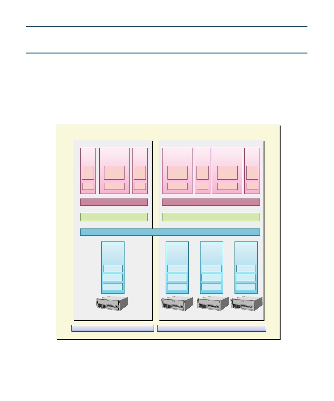
In SPARC M10 Systems, different firmware and software, such as XSCF firmware and Oracle
VM Server for SPARC, are used to configure physical partitions and logical domains.
For details on firmware and software, see "Chapter 1 Understanding an Overview of the
SPARC M10 Systems" in the Fujitsu M10/SPARC M10 Systems System Operation and
Administration Guide.
SPARC M10 Systems
(ldom10)
Oracle
Solaris
Logical domain
(Guest domain)
Logical domain
(Control domain)
(primary)
Application
Oracle
Solaris
Logical domain
(Guest domain)
(ldom00)
Applicaton
Oracle
Solaris
Logical domain
(Guest domain)
(ldom01)
Application
Oracle
Solaris
Logical domain
(Control domain)
(primary)
Application Application
Oracle
Solaris
Logical domain
(Guest domain)
Application
Oracle VM Server for SPARCOracle VM Server for SPARC
HypervisorHypervisor
XSCF
System board
(PSB#00)
CPU
Memory
I/O
System board
(PSB#01)
CPU
Memory
I/O
System board
(PSB#02)
CPU
Memory
I/O
BB#00 BB#01 BB#02 BB#03
Physical partition(PPAR#00)
Physical partition(PPAR#01)
(ldom11)
Oracle
Solaris
Logical domain
(Guest domain)
(ldom12)
Application
Oracle
Solaris
System board
(PSB#03)
CPU
Memory
I/O
- 4 -
Page 5

The main firmware and software used in SPARC M10 Systems are as follows.
XSCF Firmware
The XSCF firmware is a system control facility mounted on SPARC M10 Systems as standard.
The XSCF firmware runs on a dedicated processor (service processor) that is independent of
the processors in the server.
The XSCF firmware is placed in each chassis of SPARC M10-1, SPARC M10-4, and SPARC
M10-4S. The XSCF firmware interacts with a logical domain and controls the entire system.
If the system is comprised of multiple SPARC M10-4S chassis connected using the building
block (BB) configuration, a service processor is placed in each SPARC M10-4S chassis and
each crossbar box (XBBOX) that connects these chassis. The XSCF firmware runs on the service processor.
Hypervisor
Different firmware and software run in SPARC M10 Systems. They include the XSCF firmware that monitors and controls the entire system and Oracle Solaris that is installed in logical
domains. The Hypervisor firmware, which is placed between the XSCF firmware and Oracle
Solaris, provides an interface that transfers the setting information from the XSCF to the logical
domains and reports the status of the logical domains to the XSCF.
Oracle VM Server for SPARC
Oracle VM Server for SPARC is software for configuring a logical domain environment. It is used
by installing it in the Oracle Solaris environment.
- 5 -
Page 6

External Views of the Chassis and System
Configuration Examples
The following pages show external views of the chassis and system configuration examples
for different models.
- 6 -
Page 7
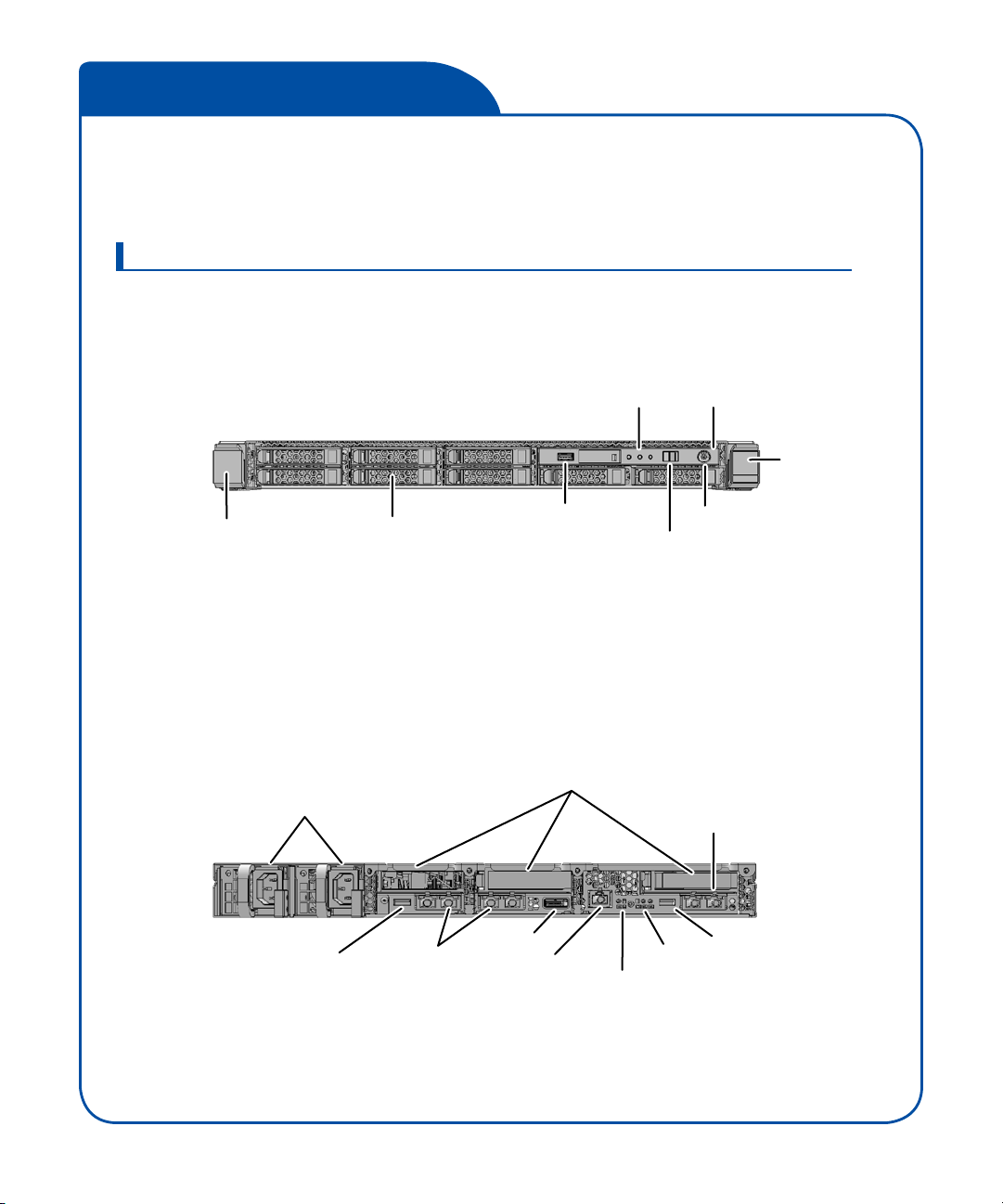
SPARC M10-1
A single SPARC M10-1 is used in this configuration.
Up to three PCI expansion units can be connected to it.
External views of the SPARC M10-1 chassis
Front view
Rear view
Lever
Power supply units
Disk drive
Panel LEDs
USB port
Mode switch
PCI Express slots
Operation panel
Lever
Power switch
XSCF-LAN port
USB port GbE LAN ports
SAS port
Serial port
- 7 -
XSCF USB port
XSCF LED
Locator LED
Page 8

SPARC M10-4
A single SPARC M10-4 unit is used, not as a building block, in this configuration.
Up to eleven PCI expansion units can be connected to it.
External views of the SPARC M10-4 chassis
Front view
Front cover
Fan unit (*)
Operation panel
USB port
Rear view
Power supply units
Power switch
Disk drive
Power supply unit (*)
*: You can see the fan unit and the power supply unit by removing the front cover.
XSCF USB port
Serial port
USB port
SAS port
GbE LAN ports
Panel LEDs
XSCF-LAN port
XSCF LED
PCI Express slot
Mode switch
- 8 -
Page 9

SPARC M10-4S
(1)
Multiple SPARC M10-4S units are connected in a building block configuration.
This model can start with a single-BB configuration and then be expanded to a multiBB configuration with the addition of individual chassis.
The model contains a crossbar unit for logically switching the connections of CPU/
memory board units and I/O units.
Reference
System configuration example - building block configuration
(connected through crossbar boxes)
Up to eight PCI expansion units can be connected to one SPARC M10-4S unit.
External views of the SPARC M10-4S chassis
Front view
Front cover
Fan unit (*)
Operation panel
USB port
*: You can see the fan unit and the power unit by removing the front cover.
Rear view
XSCF USB port
Power supply units
Serial port
SAS port
Disk drive
Power supply unit (*)
XSCF-LAN port
XSCF LEDs
USB port
Panel LEDs
BB-ID switch
XSCF BB control port
XSCF DUAL control port
PCI Express slot
GbE LAN ports
Power switch
Mode switch
Crossbar unit
Crossbar cable
ports
- 9 -
Page 10

SPARC M10-4S
(2)
External views of the crossbar box
The crossbar box is a switch used to logically connect the CPU and SPARC
M10-4S.
There are two types of crossbar boxes: one has two mounted crossbar units, and
the other has three mounted crossbar units.
Front view
(common to both types, which have two/three mounted crossbar units)
Front cover
Fan unit (*)
Operation panel
*: You can see the fan unit by removing the front cover.
Rear view
(type containing two crossbar units)
This type is used in 2-BB to 8-BB configurations (the building blocks are
connected through crossbar boxes).
XSCF unit
XSCF USB port
Serial port
Power supply units
XSCF-LAN port
XSCF LEDs
Crossbar units
XSCF DUAL control port
XSCF BB control port
Crossbar cable ports
Panel LEDs
BB-ID switch
Power switch
Mode switch
Rear view
(type containing three crossbar units)
This type is used in 9-BB to 16-BB
configurations (the building blocks are
connected through crossbar boxes).
XSCF unit
XSCF USB port
Serial port
Power supply units
XSCF-LAN port
XSCF DUAL control port
XSCF LEDs
XSCF BB control port
Crossbar units
Crossbar cable ports
- 10 -
Page 11

SPARC M10-4S
(3)
System configuration example
– building block configuration (directly connected chassis)
In this configuration, the SPARC M10-4S units are directly connected with electric
cables without using crossbar boxes.
Four-BB configuration (1 BB to 4 BBs)
Up to four SPARC M10-4S units can be connected.
BB#00
BB#01
Building block numbers are identifiers (BB-IDs) that are numbered sequentially
starting with 00.
For the connection procedure, see the Fujitsu M10/SPARC M10 Systems
Installation Guide.
BB#02
BB#03
: Crossbar unit
: Power cable
System configuration example
– building block conguration (connected through crossbar boxes)
In this configuration, building blocks are connected with optical cables through
crossbar boxes (XBBOXs).
Up to 16 SPARC M10-4S units can be connected. The number of SPARC M10-4S
units that can be connected depends on the number of crossbar boxes and the
number of crossbar units mounted in the crossbar boxes.
Eight-BB configuration (2 BBs to 8 BBs)
Up to eight SPARC M10-4S units can be connected through two crossbar boxes
containing crossbar units (two units per box).
BB#00
BB#01
BB#02
BB#03
XBBOX#80
XBBOX#81
- 11 -
BB#04
BB#05
BB#06
BB#07
OX: Crossbar boxXBBOX: Crossbar box
XBB
rossbar unit : Crossbar unit
: C
: Optical cable
: Optical cable
Page 12

SPARC M10-4S
(4)
Sixteen-BB configuration (9 BBs to 16 BBs)
Up to sixteen SPARC M10-4S units can be connected through four crossbar boxes
containing crossbar units (three units per box).
BB#00
BB#01
BB#02
BB#03
BB#04
BB#05
BB#06
BB#07
XBBOX#80
XBBOX#81
XBBOX#82
XBBOX#83
BB#08
BB#09
BB#10
BB#11
BB#12
BB#13
BB#14
BB#15
OX: Crossbar boxXBBOX: Crossbar box
XBB
Crossbar unit: Crossbar unit
:
: Optical cable: Optical cable
Each number shown after BB# or XBBOX# is an ID (BB-ID) used for identification.
Building block numbering begins with 00, and crossbar box numbering begins with 80.
For the connection procedure, see the Fujitsu M10/SPARC M10 Systems Installation
Guide.
Crossbar boxes are shipped mounted in a dedicated rack (expansion rack) together
with a dedicated power distribution unit (PDU) and crossbar cables.
An 8-BB configuration (2 BBs to 8 BBs) uses expansion rack 1, and a 16-BB configuration (9 BBs to 16 BBs) uses expansion racks 1 and 2.
- 12 -
Page 13

PCI expansion unit (Option)
The optional PCI expansion unit can be connected to either the SPARC M10-1
chassis or the SPARC M10-4/M10-4S chassis.
External views of the PCI expansion unit
Front view
Rear view
Front cover
Fan unit (*)
LED
*: You can see the fan unit by removing the front cover.
Link board
Power supply units
PCI Express slot
- 13 -
Page 14

System Specifications
This section mainly describes the hardware specifications of Athena servers. For details on firmware and software, see "Chapter 1 Understanding an Overview of the SPARC M10 Systems" in
the Fujitsu M10/SPARC M10 Systems System Operation and Administration Guide.
Model specifications (1/3)
Item SPARC M10-1 SPARC M10-4 SPARC M10-4S
External
dimensions
(*1)
Weight 18 kg 58 kg 60 kg
Maximum number of connected
units (Number of chassis)
CPU Processor SPARC64 X SPARC64 X SPARC64 X
Memory Type DDR3-DIMM DDR3-DIMM DDR3-DIMM
Height 1U 4U 4U
Height x width x depth 42.5 mm x 431 mm x
721 mm
(1.7 in. x 17.0 in. x
28.4 in.)
- - 4
Clock count 2.8 GHz 2.8 GHz 3.0 GHz
Maximum number of
CPUs
Number of cores
(per CPU)
Number of threads
(per core)
Primary cache
(per core)
Secondary cache
(per chip)
Maximum size 1 TB 4 TB 4 TB
Maximum number
of mounted memory
modules
Unit of expansion 4
1 4 4
16 16 16
2 2 2
64 KB 64 KB 64 KB
22 MB 24 MB 24 MB
16 64 64
(8 when memory
mirroring is enabled)
175 mm x 440 mm x
746 mm
(6.9 in. x 17.3 in. x
29.4 in.)
8 8
175 mm x 440 mm x
810 mm
(6.9 in. x 17.3 in. x
31.9 in.)
- 14 -
Page 15

Model specifications (2/3)
Item SPARC M10-1 SPARC M10-4 SPARC M10-4S
Built-in I/O Built-in disk (SAS) 8 (HDD/SSD) 8 (HDD/SSD) 8 (HDD/SSD)
Built-in disk hardware
RAID
Built-in CD-RW/
DVD-RW drive
Built-in tape drive Not mounted Not mounted Not mounted
On-board interface 4 GbE LAN ports
PCIe slot 3 slots 11 slots 8 slots
I/O slot
(when
using PCI
expansion
unit)
Redundant conguration Built-in disk drive/fan
Active replacement Built-in disk drive/fan
Supported operating systems (*5) Oracle Solaris 11.1
Virtuali zation
Maximum number of
PCIe slots
(built-in + PCI expansion unit)
Maximum number of
connected PCI expansion units
Physical partition None None Supported
Number of partitions – – 1
Granularity – – In building block (BB)
Logical domains Supported Supported Supported
Number of domains 32 128 256 (in physical parti-
Granularity (CPU) In units of threads In units of threads In units of threads
Granularity (Memory)
Granularity (I/O) In virtual I/O units In virtual I/O units In virtual I/O units
Mounted Mounted Mounted
Not mounted Not mounted Not mounted
4 GbE LAN ports
1 SAS port
2 USB ports
33 121 88
2 6 (in 4-CPU
unit/power supply unit/
power cord
unit/power supply unit/
power cord
Oracle Solaris 10 1/13
In units of 256 MB In units of 256 MB In units of 256 MB
1 SAS port
2 USB ports
conguration)
Built-in disk drive/fan
unit/power supply unit
(*2)/power cord (*2)/
PCIe card (in multi-
path conguration)/
LLC water
cooling pump
Built-in disk drive/fan
unit/power supply unit
(*2)/power cord (*2)/
PCIe card (*4)
Oracle Solaris 11.1
Oracle Solaris 10 1/13
4 GbE LAN ports
1 SAS port
2 USB ports
5 (in 4-CPU
conguration)
Built-in disk drive/fan
unit/power supply unit
(*2)/power cord (*2)/
PCIe card (in multi-
path conguration)/
LLC water
cooling pump
Building block (*3)/
built-in disk drive/fan
unit/power supply unit
(*2)/power cord (*2)/
PCIe card (*4)
Oracle Solaris 11.1
Oracle Solaris 10 1/13
units
tion units)
- 15 -
Page 16

Model specifications (3/3)
Item SPARC M10-1 SPARC M10-4 SPARC M10-4S
eXtended
System
Control
Facility (*6)
*1: None of the dimensions includes the sizes of protrusions.
*2: A redundant configuration applies only when 200 VAC is used.
*3: A single SPARC M10-4S in a building block configuration is referred to as a building block.
*4: Some PCIe card types do not support active replacement.
*5: The operating system is installed in the initial system state. For detailed software requirements, see the
Fujitsu M10/SPARC M10 Systems Product Notes.
*6: Firmware is built into the eXtended System Control Facility. This firmware is installed on the service proces-
sor in the XSCF unit in the initial system state. For details, see the Fujitsu M10/SPARC M10 Systems System
Operation and Administration Guide.
External interface 2 XSCF-LAN ports
1 serial port
1 USB port
Redundant
conguration
Active replacement Not available Not available Supported (only 2-BB
Not available Not available Supported (2 or more
2 XSCF-LAN ports
1 serial port
1 USB port
2 XSCF-LAN ports
1 serial port
1 USB port
3 XSCF BB control
ports
1 XSCF DUAL control
port
building blocks (*3))
conguration or larger)
Crossbar box specifications (1/2)
Item Crossbar box
External
dimensions (*)
Weight 40 kg
eXtended
System
Control
Facility
Crossbar connection interface - 2 crossbar units mounted
Height 4U
Height x width x depth 174 mm x 440 mm x 740 mm
(6.9 in. x 17.3 in. x 29.1 in.)
External interface 2 XSCF-LAN ports
1 serial port
1 USB port
19 XSCF BB control ports
1 XSCF DUAL control port
Redundant
conguration
Active replacement Available
Available (only between SPARC M10-4S units)
32 crossbar cable ports
- 3 crossbar units mounted
48 crossbar cable ports
- 16 -
Page 17

Crossbar box specifications (2/2)
Item Crossbar box
Redundant conguration Power supply unit/fan unit
Active replacement Power supply unit/fan unit/XSCF unit
*: None of the dimensions includes the sizes of protrusions.
PCI expansion unit specifications
Item PCI expansion unit
External
dimensions
(*1)
Weight 22 kg
Number of PCIe slots 11
Redundant conguration Power supply unit/fan unit
Active replacement Power supply unit/fan unit/PCIe card (*2)/link board (*3)
*1: None of the dimensions includes the sizes of protrusions.
*2: Some PCIe card types do not support active replacement.
*3: You can replace these units after disconnecting the PCI expansion unit from the logical domain by using the
PCI Hot Plug (PHP) function.
Height 2U
Height x width x depth 86 mm x 440 mm x 740 mm
(3.4 in. × 17.3 in. × 29.1 in.)
- 17 -
Page 18

What Do I Do Now? Reference Guide (by Phase/Purpose)
This section describes the work for each phase, from system installation to expansion and maintenance, and the reference manuals for each work item.
indicates a required work item, and indicates a work item to be performed as
required.
1. Installation
1-a. Understanding overview
1-b. Installing and
connecting
1-c. Adding optional
component
1-d. Initial settings
(XSCF, resource)
2-c. Conguring system (*)
(Power supply setting,
etc.)
2-d. Conguring virtual
environment (*)
2-e. Conguring reliability
(*) (Mirror conguration,
RAID conguration, etc.)
2. Operation and
Administration
2-a. Daily management
(Backup, etc.)
2-b. Customizing XSCF
2-c. Conguring system (*)
(Power supply setting,
etc.)
2-d. Conguring virtual
environment (*)
2-e. Conguring reliability
(*) (Mirror conguration,
RAID conguration,
etc.)
2-f. Changing resource
conguration
3. Expansion and
Maintenance
3-a. Adding PCI expansion
unit
3-b. Adding optional
component
3-c. Adding/Removing
system in building block
conguration
3-d. Expanding resources
3-e. Diagnosing failure
3-f. Replacing component
3-g. Updating rmware/
software
*: You can configure these items as required, when configuring the initial system settings. You can also change
the settings and set values after starting operation.
- 18 -
Page 19

1. Installation
a. Understanding an overview of the system
Check the SPARC M10 Systems overview.
Reference
"Understanding an Overview of the System" (This document)
b. Installing the system - Connecting a chassis
Before installing the system, confirm that the installation location meets the
requirements. After confirmation, install and connect the chassis required for the
system configuration.
Reference
Fujitsu M10/SPARC M10 Systems Installation Guide
"1.1 Workow for the SPARC M10-1"
"1.2 Workow for the SPARC M10-4"
"1.3 Workow for the SPARC M10-4S"
"1.4 Workow when Connecting the PCI Expansion Unit"
c. Adding an optional component
If you have ordered any option, such as a memory module or PCIe card, mount the
additional component during installation.
Reference
Fujitsu M10-1/SPARC M10-1 Service Manual
Fujitsu M10-4/Fujitsu M10-4S/SPARC M10-4/SPARC M10-4S
Service Manual
PCI Expansion Unit for Fujitsu M10/SPARC M10 Systems
Service Manual
d. Configuring the initial system settings
Before starting the system, configure the initial settings of the eXtended System
Control Facility (XSCF). Use the CPU Activation function to also configure the use
of resources according to the number of purchased CPU cores activated.
Reference
In addition, configure operation in, for example, a virtual environment configuration,
as necessary.
Fujitsu M10/SPARC M10 Systems Installation Guide
"Chapter 6 Performing an Initial System Diagnosis"
"Chapter 7 Making the Initial System Settings"
- 19 -
Page 20

2. Operation and Administration
a. Conducting daily management
You should understand the basic operations, which include logging in/out from the
management console and starting/stopping the system. These basic operations are
required for system operation and management and for daily management work
items, such as backup.
Reference
Administration Guide
Fujitsu M10/SPARC M10 Systems System Operation and
"Chapter 2 Logging In/Out of the XSCF"
"Chapter 6 Starting/Stopping the System"
"Chapter 9 Managing the SPARC M10 Systems Daily"
"Chapter 13 Switching to Locked/Service Mode"
b. Customizing eXtended System Control Facility (XSCF) settings
From the initial setup of the eXtended System Control Facility, you can customize
the configuration according to your use environment.
Reference
Administration Guide
Fujitsu M10/SPARC M10 Systems System Operation and
"Chapter 3 Conguring the System"
c. Configuring the system
Configure the entire system including power control. The green IT function minimizes the power consumption of the system.
Reference
Administration Guide
Fujitsu M10/SPARC M10 Systems System Operation and
"Chapter 4 Conguring the System to Suit the Usage Type"
d. Configuring a virtual environment
You can configure a virtual environment by dividing the system into physical partitions or logical domains. You can run a standalone operating system in each logical
domain.
Reference
Fujitsu M10/SPARC M10 Systems Domain Conguration Guide
"Chapter 4 Physical Partition Conguration Example"
"Chapter 5 Logical Domain Conguration Example"
- 20 -
Page 21

2. Operation and Administration
e. Configuring a highly reliable system
You can use memory mirroring or the hardware RAID function to improve system
reliability.
Reference
Administration Guide
Fujitsu M10/SPARC M10 Systems System Operation and
"Chapter 14 Conguring a Highly Reliable System"
f. Changing the resource configuration
You can use the dynamic reconfiguration function of Oracle VM Server for SPARC
to change the CPU or memory configuration.
Reference
Fujitsu M10/SPARC M10 Systems Domain Conguration Guide
"Chapter 6 Physical Partition Reconguration Example"
- 21 -
Page 22

3. Expansion and Maintenance
a. Adding a PCI expansion unit
You can use a PCI expansion unit to increase the number of PCIe slots.
Reference
Fujitsu M10/SPARC M10 Systems Installation Guide
"1.4 Workow when Connecting the PCI Expansion Unit"
b. Adding an optional component
You can expand the system by adding an optional component such as a memory
module or PCI card.
Reference
Fujitsu M10-4/Fujitsu M10-4S/SPARC M10-4/SPARC M10-4S
Service Manual
PCI Expansion Unit for Fujitsu M10/SPARC M10 Systems
Service Manual
Fujitsu M10-1/SPARC M10-1 Service Manual
c. Adding/Removing a system in a building block configuration
You can flexibly expand or reduce the system by adding or removing a SPARC
M10-4S in the building block system.
Reference
Fujitsu M10/SPARC M10 Systems Installation Guide
"Chapter 8 Before Installing/Removing a System with
a Building Block Conguration"
"Chapter 9 Installing a System with a Building Block
Conguration"
"Chapter 10 Removing a System with a Building Block
Conguration"
Fujitsu M10/SPARC M10 Systems Domain Conguration Guide
"Chapter 6 Physical Partition Reconguration Example"
d. Expanding resources according to the load
You can use the CPU Activation function for CPU expansion in units of two cores
when the load increases.
Reference
Administration Guide
Fujitsu M10/SPARC M10 Systems System Operation and
"Chapter 5 CPU Activation"
- 22 -
Page 23

3. Expansion and Maintenance
e. Diagnosing a failure
If an error message appears on the console or the CHECK LED on the chassis
goes on, diagnose whether a failure has occurred.
Reference
Fujitsu M10-4/Fujitsu M10-4S/SPARC M10-4/SPARC M10-4S
Service Manual
PCI Expansion Unit for Fujitsu M10/SPARC M10 Systems
Service Manual
Fujitsu M10-1/SPARC M10-1 Service Manual
f. Replacing faulty components
Replace faulty components. The maintenance method varies with the component.
Our service engineers should perform the maintenance work.
Reference
Fujitsu M10-4/Fujitsu M10-4S/SPARC M10-4/SPARC M10-4S
Service Manual
PCI Expansion Unit for Fujitsu M10/SPARC M10 Systems
Service Manual
Fujitsu M10-1/SPARC M10-1 Service Manual
g. Updating firmware/software
Update the firmware for Oracle VM Server for SPARC and Oracle Solaris.
Reference
Administration Guide
Fujitsu M10/SPARC M10 Systems System Operation and
"Chapter 16 Updating Firmware/Software"
PCI Expansion Unit for Fujitsu M10/SPARC M10 Systems
Service Manual
"Appendix C Updating the Firmware of
the PCI Expansion Unit"
- 23 -
 Loading...