

Page 1

FUJITSU Storage
ETERNUS LT260 Tape Library
User's Guide -Panel Operation-
P3AM-8802-09ENZ0
Page 2

This page is intentionally left blank.
Page 3

Preface
Fujitsu would like to thank you for purchasing our FUJITSU Storage ETERNUS LT260 Tape Library (hereinafter
referred to as LT260).
The LT260 is designed to be connected to servers (such as PRIMEQUEST, PRIMERGY, or Fujitsu M12/M10).
This manual explains how to perform operation management and settings for the LT260 from the operator
panel or the remote panel.
This manual is intended for use of LT260 in regions other than Japan.
Please carefully review the information outlined in this manual.
Ninth Edition
December 2019
LTO, Linear Tape-Open, and Ultrium are registered trademarks of Hewlett Packard Enterprise, L.P., IBM Corporation, and Quantum Corporation.
All SPARC trademarks are used under license and are trademarks or registered trademarks of SPARC International, Inc. in the United States and other countries.
Microsoft, Windows, and Internet Explorer are either registered trademarks or trademarks of Microsoft Corporation in the United States and/or other countries.
The company names, product names and service names mentioned in this document are registered trademarks or trademarks of their respective companies.
Microsoft product screen shot(s) reprinted with permission from Microsoft Corporation.
3
FUJITSU Storage ETERNUS LT260 Tape Library User’s Guide -Panel Operation-
Copyright 2019 FUJITSU LIMITED P3AM-8802-09ENZ0
Page 4
Organization
WARNING
CAUTION
Electric Shock
No Disassembly
This manual is composed of the following two chapters:
● Chapter 1 Overview
This chapter provides an overview of the operator panel and the remote panel.
● Chapter 2 Operating the Library
This chapter provides information about various operations that can be performed with the operator panel
and the remote panel.
Warning Notations
About this Manual
Warning signs are shown throughout this manual in order to prevent injury to the user and/or material damage. These signs are composed of a symbol and a message describing the recommended level of caution. The
following explains the symbols, their levels of caution, and their meanings as used in this manual.
This symbol indicates the possibility of serious or fatal injury if the LT260 is not
used properly.
This symbol indicates the possibility of minor or moderate personal injury, as
well as damage to the LT260 and/or to other users and their property, if the
LT260 is not used properly.
This symbol indicates IMPORTANT information for the user to note when using
the LT260.
The following symbols are used to indicate the type of warnings or cautions being described.
The triangle emphasizes the urgency of the WARNING and CAUTION contents. Inside the triangle and above it are details concerning the symbol
(e.g. Electrical Shock).
The barred "Do Not..." circle warns against certain actions. The action which
must be avoided is both illustrated inside the barred circle and written above it
(e.g. No Disassembly).
4
FUJITSU Storage ETERNUS LT260 Tape Library User’s Guide -Panel Operation-
Copyright 2019 FUJITSU LIMITED P3AM-8802-09ENZ0
Page 5
About this Manual
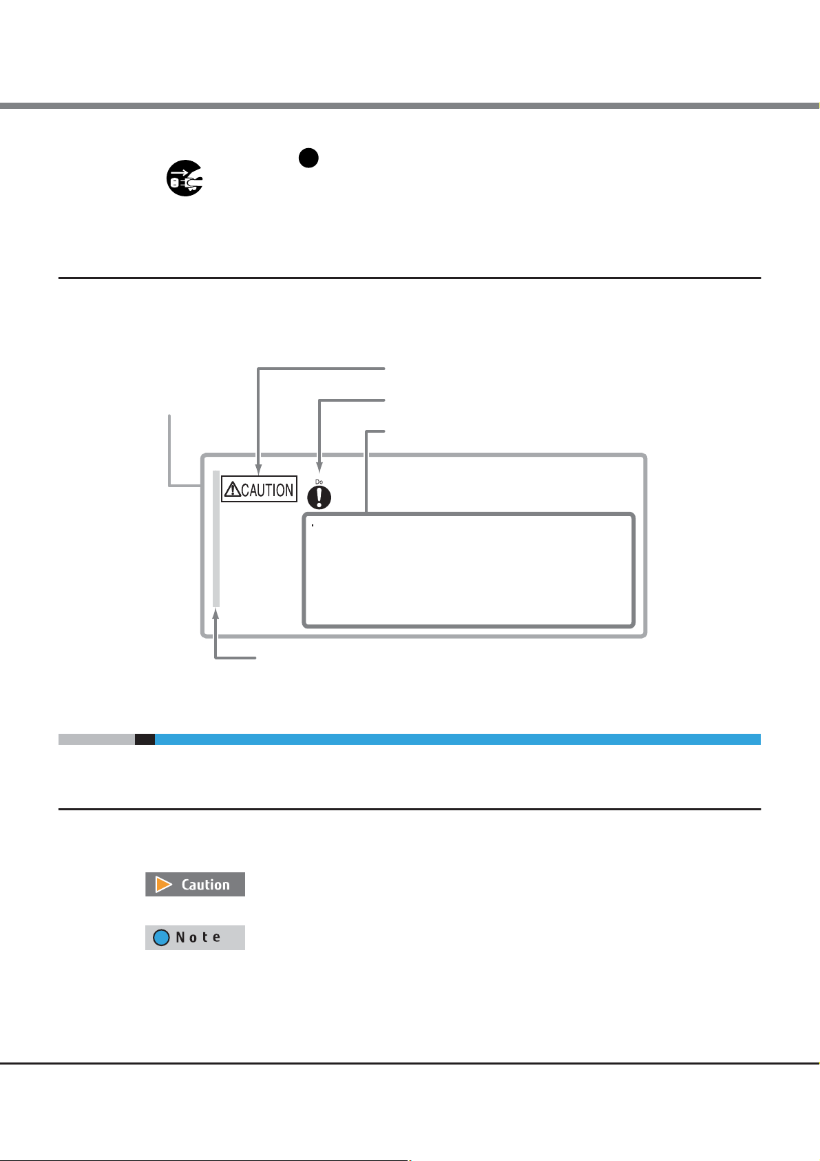
Unplug
Warning Level Indicator
Warning Type Indicator
Warning Details
To avoid damaging the LT260, pay attention to the following points
when cleaning the LT260:
- Make sure to disconnect the power when cleaning.
- Be careful that no liquid seeps into the LT260 when using cleaners, etc.
- Do not use alcohol or other solvents to clean the LT260.
Warning Layout Ribbon
Example Warning
The black "Must Do..." disk indicates actions that must be taken. The
required action is both illustrated inside the black disk and written above it
(e.g. Unplug).
How Warnings are Presented in this Manual
A message is written beside the symbol indicating the caution level. This message is marked with a vertical
ribbon in the left margin, to distinguish this warning from ordinary descriptions.
An example is shown here.
Additional Information
Symbols Used in This Manual
The following symbols are used throughout this manual:
This symbol alerts operators to particularly important information. Be sure to read this
information.
Functions and know how which can be useful when setting up or operating the LT260.
5
FUJITSU Storage ETERNUS LT260 Tape Library User’s Guide -Panel Operation-
Copyright 2019 FUJITSU LIMITED P3AM-8802-09ENZ0
Page 6

About this Manual
Abbreviations Used in This Manual
• “LT260” refers to the FUJITSU Storage ETERNUS LT260 Tape Library.
• Trademark symbols such as ™ and ® are omitted in this manual.
6
FUJITSU Storage ETERNUS LT260 Tape Library User’s Guide -Panel Operation-
Copyright 2019 FUJITSU LIMITED P3AM-8802-09ENZ0
Page 7

Table of Contents
Chapter 1 Overview 12
1.1 Overview of Panel Operations ........................................................................................... 12
1.1.1 Overview of the Operator Panel ..................................................................................................................... 12
1.1.2 Overview of the Remote Panel ....................................................................................................................... 14
1.2 Operation Window ............................................................................................................15
1.2.1 Window Layout ..............................................................................................................................................15
1.3 Menu Layout ..................................................................................................................... 16
1.3.1 Menu Layout of the Operator Panel ............................................................................................................... 16
1.3.2 Menu Layout of the Remote Panel ................................................................................................................ 17
Chapter 2 Operating the Library 18
2.1 Using the Operator Panel .................................................................................................. 19
2.2 Using the Remote Panel ................................................................................................... 20
2.3 Logging into the Library ................................................................................................... 21
2.4 Using the Library Home Screen ......................................................................................... 23
2.4.1 Top Banner Elements .................................................................................................................................... 24
2.4.2 Left Pane Elements ........................................................................................................................................ 24
2.4.3 Center Panel Elements .................................................................................................................................. 26
2.5 Configuring the Library .....................................................................................................27
2.5.1 Using the Initial Configuration Wizard ........................................................................................................... 27
2.5.2 Saving, Restoring and Resetting the Library Configuration ............................................................................31
2.5.3 Configuring the Date and Time Format .......................................................................................................... 34
2.5.4 Configuring Media Barcode Compatibility Checking ...................................................................................... 38
2.5.5 Configuring Allow Unlabeled Media Setting ..................................................................................................39
2.5.6 Configuring License Key Handing ..................................................................................................................40
2.5.7 Configuring the RMI Timeout Setting (for Firmware Versions 7.80 and Earlier) .............................................41
2.5.8 Configuring the Library Network Settings ......................................................................................................42
2.5.9 Configuring the SNMP ....................................................................................................................................43
2.5.10 Configuring the SMTP ....................................................................................................................................47
2.5.11 Configuring Tape Drives .................................................................................................................................49
2.5.12 Enabling or Disabling Mailslots ..................................................................................................................... 51
2.5.13 Configuring Library Partitions ........................................................................................................................ 52
2.5.14 Configuring Key Management Function ......................................................................................................... 57
2.5.15 Configuring User Account Settings (for Firmware Versions 7.80 and Earlier) .................................................58
2.5.16 Configuring User Account Settings (for Firmware Versions 7.90 and Later) ...................................................60
7
FUJITSU Storage ETERNUS LT260 Tape Library User’s Guide -Panel Operation-
Copyright 2019 FUJITSU LIMITED P3AM-8802-09ENZ0
Page 8

Table of Contents
2.5.17 Configuring Password Requirements (for Firmware Versions 7.90 and Later) ................................................66
2.5.18 Configuring the Access Management Setting to the Remote Panel ............................................................... 68
2.6 Maintaining the Library .................................................................................................... 82
2.6.1 Library Tests ..................................................................................................................................................82
2.6.2 Viewing Log Files ...........................................................................................................................................90
2.6.3 Managing System Firmware ..........................................................................................................................92
2.6.4 Managing Drive Firmware .............................................................................................................................93
2.6.5 Downloading Drive Logs ................................................................................................................................ 94
2.6.6 Downloading Log and Trace Files ..................................................................................................................96
2.6.7 Rebooting the Library .................................................................................................................................... 96
2.6.8 Tape Drive Reboot ......................................................................................................................................... 97
2.6.9 Controlling the UID LED .................................................................................................................................98
2.6.10 Moving the Robotic to the Base Module ........................................................................................................98
2.7 Operating the Library ........................................................................................................ 99
2.7.1 Moving Media ................................................................................................................................................ 99
2.7.2 Opening the Mailslot ................................................................................................................................... 100
2.7.3 Opening a Magazine ................................................................................................................................... 102
2.7.4 Cleaning a Tape Drive .................................................................................................................................. 103
2.7.5 Rescanning the Cartridge Inventory ............................................................................................................. 104
2.7.6 Forcing a Tape Drive to Eject a Cartridge ...................................................................................................... 105
2.8 Viewing Status Information ............................................................................................ 106
2.8.1 Viewing Library and Module Status ............................................................................................................. 106
2.8.2 Using Inventory Lists ...................................................................................................................................109
2.8.3 Using Inventory Graphical View ...................................................................................................................111
2.8.4 Partition Map Graphical View ...................................................................................................................... 113
2.8.5 Using Partition Map Configuration Status .................................................................................................... 116
2.8.6 Viewing Tape Drive Status ........................................................................................................................... 118
2.8.7 Viewing Network Status ...............................................................................................................................119
2.8.8 Viewing Security Status ................................................................................................................................ 121
8
FUJITSU Storage ETERNUS LT260 Tape Library User’s Guide -Panel Operation-
Copyright 2019 FUJITSU LIMITED P3AM-8802-09ENZ0
Page 9

List of Figures
Figure 1.1 Initialization window................................................................................................................................... 13
Figure 1.2 Login window.............................................................................................................................................. 13
Figure 1.3 Remote panel starting window ................................................................................................................... 14
Figure 1.4 Home screen configuration ......................................................................................................................... 15
Figure 1.5 Menu layout of the operator panel.............................................................................................................. 16
Figure 1.6 Menu layout of the remote panel................................................................................................................ 17
Figure 2.1 Login........................................................................................................................................................... 21
Figure 2.2 Home screen ............................................................................................................................................... 23
Figure 2.3 Save/Restore configuration.......................................................................................................................... 31
Figure 2.4 Time zone.................................................................................................................................................... 34
Figure 2.5 Date/Time format ........................................................................................................................................ 35
Figure 2.6 Set date/time............................................................................................................................................... 36
Figure 2.7 SNTP............................................................................................................................................................ 37
Figure 2.8 Media barcode compatibility check ............................................................................................................. 38
Figure 2.9 Allow unlabeled media................................................................................................................................ 39
Figure 2.10 License key handing.................................................................................................................................... 40
Figure 2.11 RMI timeout ................................................................................................................................................ 41
Figure 2.12 Network setting........................................................................................................................................... 42
Figure 2.13 SNMP........................................................................................................................................................... 43
Figure 2.14 SNMPv3....................................................................................................................................................... 46
Figure 2.15 SMTP ........................................................................................................................................................... 47
Figure 2.16 Tape drive settings ...................................................................................................................................... 49
Figure 2.17 Enabling or disabling mailslots ................................................................................................................... 51
Figure 2.18 Setting re-lock time..................................................................................................................................... 52
Figure 2.19 User accounts settings................................................................................................................................. 58
Figure 2.20 User account settings .................................................................................................................................. 60
Figure 2.21 Adding an Account ...................................................................................................................................... 62
Figure 2.22 Changing the Account Password.................................................................................................................. 63
Figure 2.23 Changing the User Account Role.................................................................................................................. 64
Figure 2.24 Deleting an account .................................................................................................................................... 65
Figure 2.25 Password setting requirements ................................................................................................................... 67
Figure 2.26 Access management setting to the remote panel (for firmware versions 7.80 and earlier) ........................ 68
Figure 2.27 Access management setting to the remote panel (for firmware versions 7.90 and later) ........................... 69
Figure 2.28 Enabling the SSL setting.............................................................................................................................. 70
Figure 2.29 Certificate settings....................................................................................................................................... 71
Figure 2.30 Self signed certificate creation screen ......................................................................................................... 72
Figure 2.31 Information screen ...................................................................................................................................... 73
Figure 2.32 Certificate Signing Request screen 1............................................................................................................ 74
Figure 2.33 Certificate Signing Request screen 2............................................................................................................ 75
Figure 2.34 Signed Certificate screen ............................................................................................................................. 76
Figure 2.35 Finish screen ............................................................................................................................................... 77
Figure 2.36 Backing up the self-signed certificate.......................................................................................................... 78
Figure 2.37 Restoring the self signed certificate ............................................................................................................ 78
Figure 2.38 Setting the session timeout......................................................................................................................... 79
Figure 2.39 Setting login session locking function ......................................................................................................... 79
Figure 2.40 Disabled login session locking function.............................................................................
2.41 Enabled login session locking function ....................................................................................................... 80
e
Figur
Figure 2.42 Remote panel restriction setting ................................................................................................................. 81
.......................... 80
9
FUJITSU Storage ETERNUS LT260 Tape Library User’s Guide -Panel Operation-
Copyright 2019 FUJITSU LIMITED P3AM-8802-09ENZ0
Page 10

List of Figures
Figure 2.43 System test.................................................................................................................................................. 82
Figure 2.44 Slot to slot test ............................................................................................................................................ 83
Figure 2.45 Element to element test.............................................................................................................................. 84
Figure 2.46 Position test ................................................................................................................................................ 86
Figure 2.47 Wellness test ............................................................................................................................................... 88
Figure 2.48 Robotic test ................................................................................................................................................. 89
Figure 2.49 OCP test....................................................................................................................................................... 89
Figure 2.50 View logs..................................................................................................................................................... 90
Figure 2.51 Detailed view example for logs ................................................................................................................... 91
Figure 2.52 Upgrades system firmware .......................................................................................................................... 92
Figure 2.53 Upgrades drive firmware ............................................................................................................................. 93
Figure 2.54 Download drive logs.................................................................................................................................... 94
Figure 2.55 Download logs and traces ........................................................................................................................... 96
Figure 2.56 Rebooting the library .................................................................................................................................. 96
Figure 2.57 Tape drive reboot ........................................................................................................................................ 97
Figure 2.58 UID LED control ........................................................................................................................................... 98
Figure 2.59 Move robotic to base module ...................................................................................................................... 98
Figure 2.60 Move media ................................................................................................................................................ 99
Figure 2.61 Open mailslot............................................................................................................................................ 101
Figure 2.62 Open magazine......................................................................................................................................... 102
Figure 2.63 Clean drive ................................................................................................................................................ 103
Figure 2.64 Rescan inventory ....................................................................................................................................... 104
Figure 2.65 Force drive media eject ............................................................................................................................. 105
Figure 2.66 Library status............................................................................................................................................. 106
Figure 2.67 Inventory list ............................................................................................................................................. 109
Figure 2.68 Inventory graphical view ........................................................................................................................... 111
Figure 2.69 Inventory graphical view (display status).................................................................................................. 112
Figure 2.70 Inventory graphical view (display error status).......................................................................................... 113
Figure 2.71 Partition map graphical view..................................................................................................................... 113
Figure 2.72 Partition map graphical view (display partition information) ................................................................... 114
Figure 2.73 Partition map graphical view (tape drive information display) ................................................................. 115
Figure 2.74 Using partition map configuration status.................................................................................................. 116
Figure 2.75 Tape drive status ....................................................................................................................................... 118
Figure 2.76 Network status .......................................................................................................................................... 119
Figure 2.77 Viewing security status.............................................................................................................................. 121
10
FUJITSU Storage ETERNUS LT260 Tape Library User’s Guide -Panel Operation-
Copyright 2019 FUJITSU LIMITED P3AM-8802-09ENZ0
Page 11

List of Tables
Table 2.1 Status icons ................................................................................................................................................. 18
Table 2.2 Front panel LED indicators .......................................................................................................................... 19
Table 2.3 Management software ................................................................................................................................ 43
11
FUJITSU Storage ETERNUS LT260 Tape Library User’s Guide -Panel Operation-
Copyright 2019 FUJITSU LIMITED P3AM-8802-09ENZ0
Page 12

Chapter 1
Overview
This chapter provides an overview of the operator panel and the remote panel.
1.1 Overview of Panel Operations
The library provides two main interfaces:
• Operator panel
With the operator panel, you can monitor, configure, and control the library from the front panel. All operating menus are displayed on the center pane.
• Remote panel
With the remote panel, you can monitor, configure, and control the library from a web browser. The remote
panel hosts a dedicated, protected Internet site that displays a graphical representation of the library.
Except of top menus, operating menu tree are displayed on the right pane.
Although the operator panel is similar to the remote panel in design and functionality, some of the executable operations are different.
1.1.1 Overview of the Operator Panel
The operator panel is positioned on the center of the front panel. It is possible to perform operations such as
referencing/setting the library and drive status and opening the magazine or mailslot from the operator
panel. By selecting the buttons on the operator panel, operations such as window transition, function selection, and setup value input can be performed.
The windows on the operator panel before login can be roughly divided into the initialization window and
login window.
12
FUJITSU Storage ETERNUS LT260 Tape Library User’s Guide -Panel Operation-
Copyright 2019 FUJITSU LIMITED P3AM-8802-09ENZ0
Page 13
Chapter 1 Overview
1.1 Overview of Panel Operations
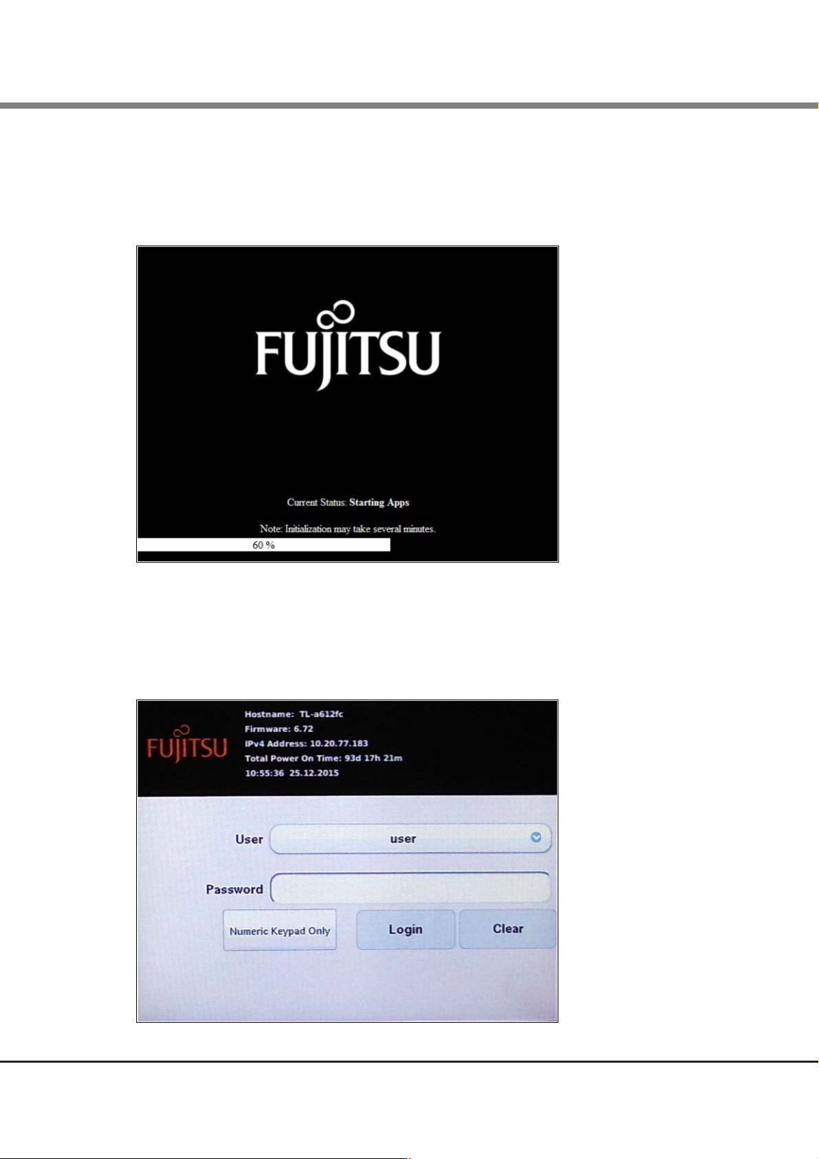
■ Initialization window
Initialization is started when the library is turned on. In the initialization window, the progress status of the
library initializing are displayed.
Figure 1.1 Initialization window
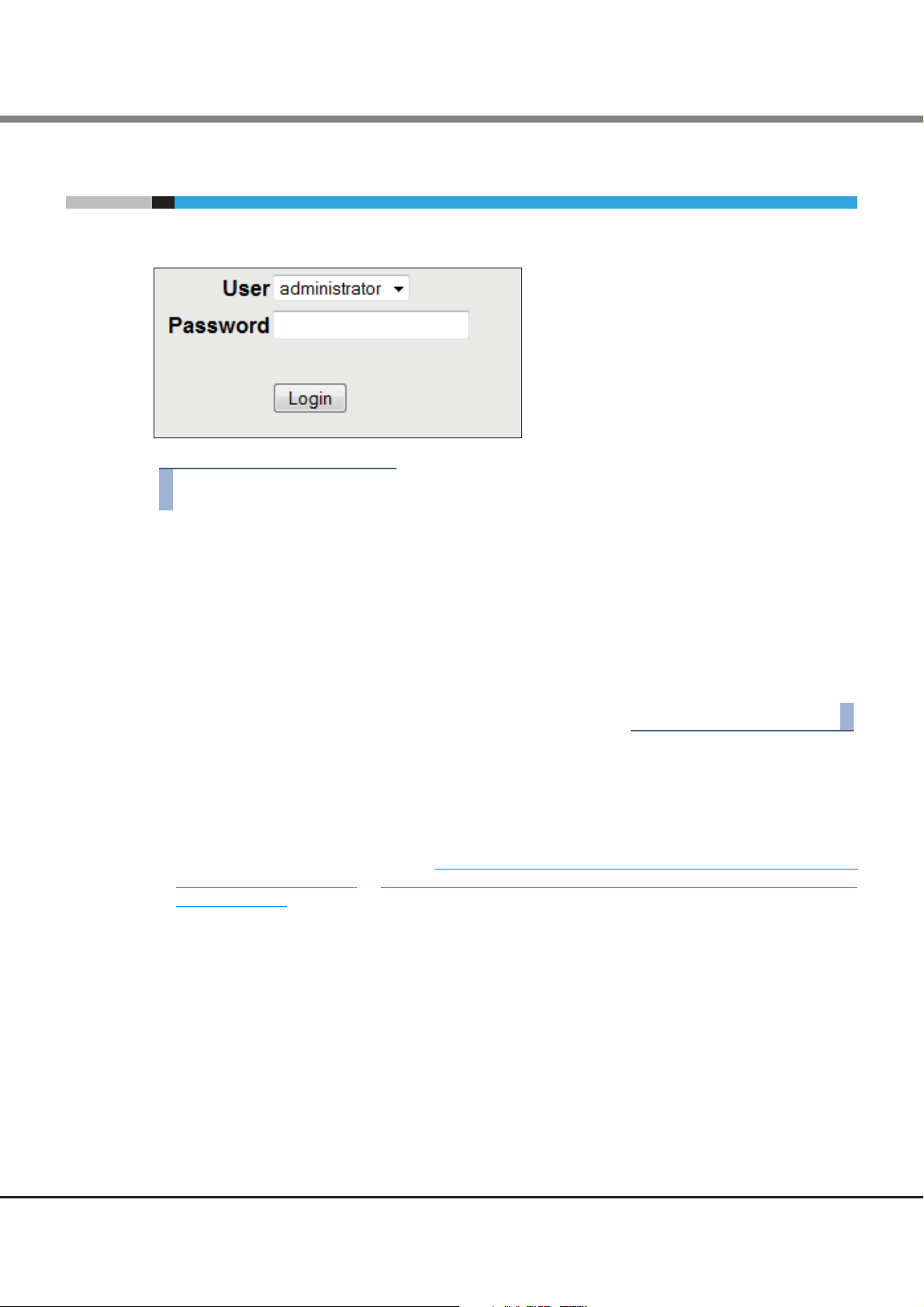
■ Login window
When initialization operation ends, the login window is displayed on the operator panel.
If the screen saver is on, please tap the screen.
Figure 1.2 Login window
13
FUJITSU Storage ETERNUS LT260 Tape Library User’s Guide -Panel Operation-
Copyright 2019 FUJITSU LIMITED P3AM-8802-09ENZ0
Page 14
Chapter 1 Overview
1.1 Overview of Panel Operations
1.1.2 Overview of the Remote Panel
The remote panel can be used to perform operations such as referencing/setting the library and drive status
and performing drive cleaning on a Web browser via the LAN.
• The recommended environment for the remote panel is as follows:
- Web browser
Microsoft Internet Explorer, Mozilla Firefox, Google Chrome, Safari
• Cookies and Java Script are used for the remote panel. Cookies and Java Script need to be enabled in your
browser.
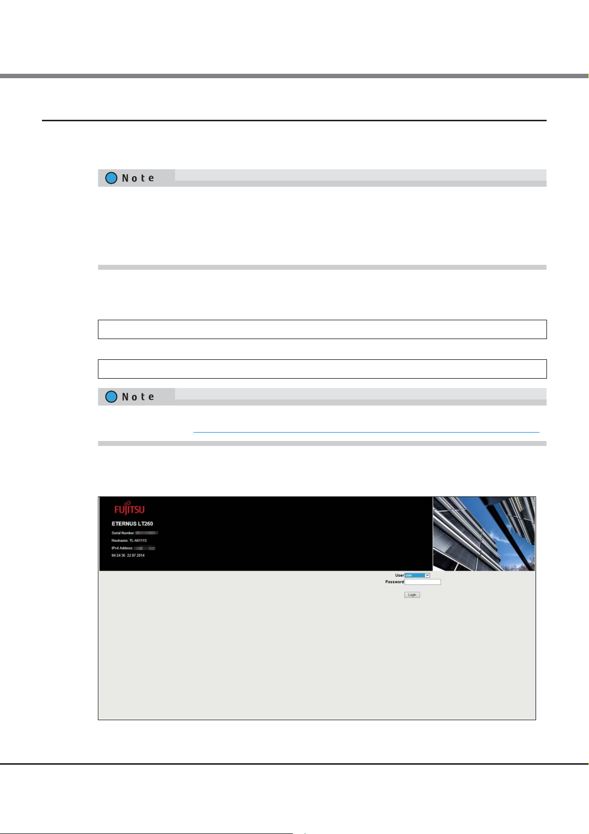
Before using the remote panel, network settings need to be performed on the operator panel to enable the IP
address, the subnet mask, and the gateway so that the remote panel can be used. Specify the following URL
on a Web browser after performing the settings:
http:// <IP address specified for the LT260>/
or
https:// <IP address specified for the LT260>/
Use the https URL to connect to the remote panel for the LT260 when SSL is enabled. For details related to
enabling SSL, refer to "2.5.18
The following window is displayed when the LT260 is connected.
Figure 1.3 Remote panel starting window
Configuring the Access Management Setting to the Remote Panel" (page 68).
14
FUJITSU Storage ETERNUS LT260 Tape Library User’s Guide -Panel Operation-
Copyright 2019 FUJITSU LIMITED P3AM-8802-09ENZ0
Page 15
Chapter 1 Overview
Top banner
Left pane
Center pane
Right pane
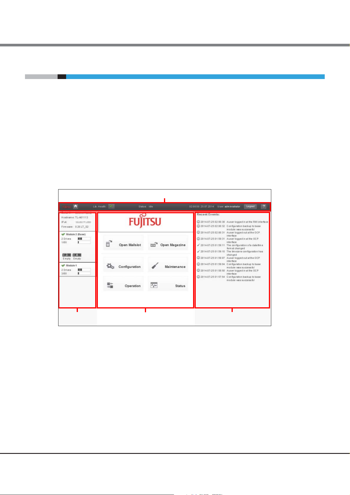
1.2 Operation Window
1.2 Operation Window
1.2.1 Window Layout
The home screen window is displayed after login. See "2.4 Using the Library Home Screen" (page 23) for
details.
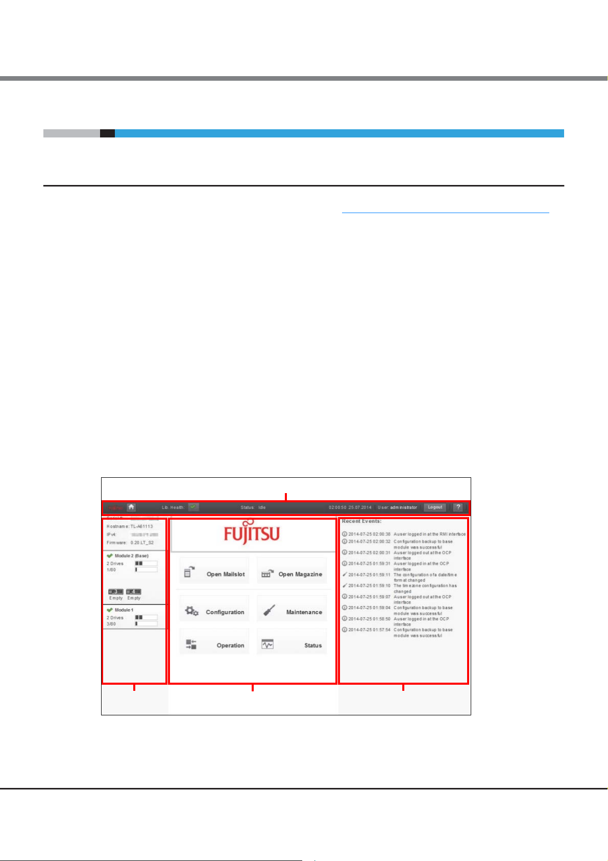
The library home screen is organized into the following regions:
● Top banner
Contains the home button and displays the overall status and information about the library and user.
● Left pane
Displays the library identity and module status.
● Center pane
Provides access to operate and configure the library and to view additional status information.
● Right pane (remote panel only)
Displays a log of recent events.
Figure 1.4 Home screen configuration
15
FUJITSU Storage ETERNUS LT260 Tape Library User’s Guide -Panel Operation-
Copyright 2019 FUJITSU LIMITED P3AM-8802-09ENZ0
Page 16

Chapter 1 Overview
1.3 Menu Layout
1.3 Menu Layout
This section describes the menu layout of the operator panel and the remote panel.
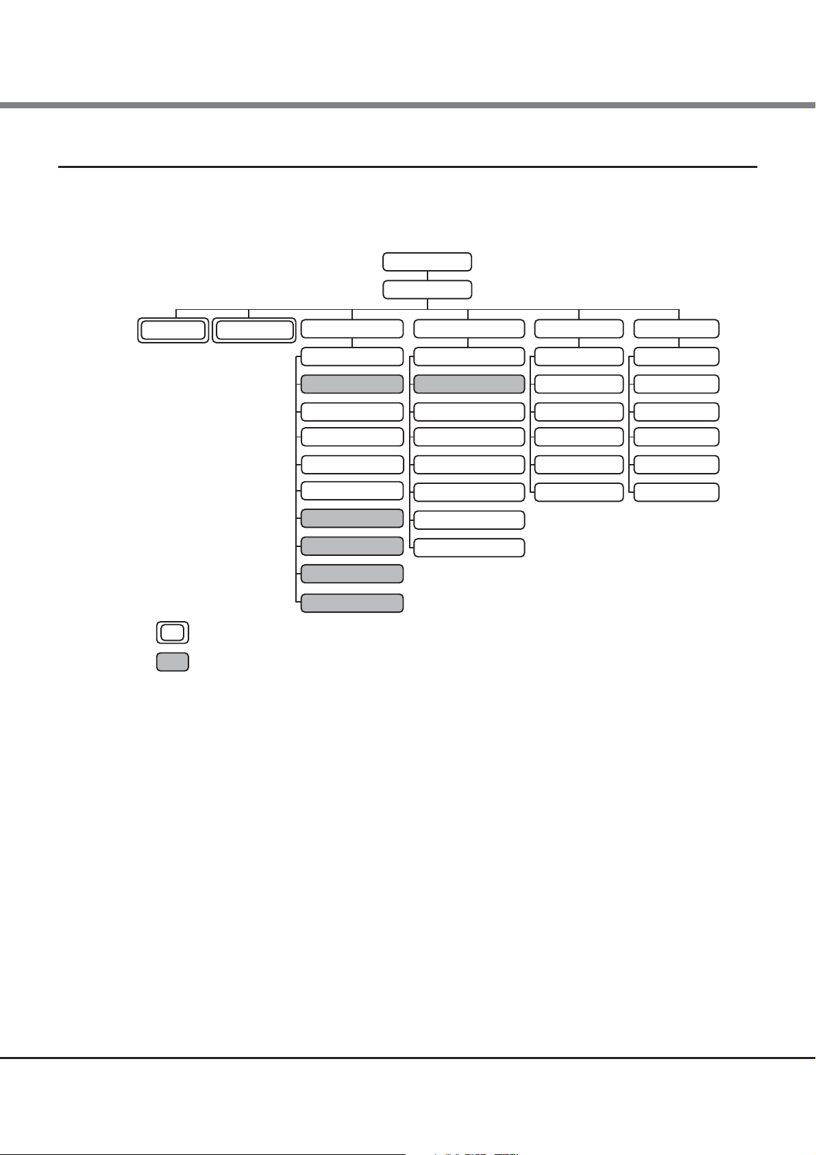
1.3.1 Menu Layout of the Operator Panel
The menu layout of the operator panel is as follows.
Figure 1.5 Menu layout of the operator panel
Login
Home
Open Mailslot
Open Magazine Configuration Maintenance Operation Status
Configuration Wizard
System
Network
Drives
Mailslot
Local User Accounts
Web Management
Although the Open Mailslot menu and the Open Magazine menu are in both the Home menu and the Operation menu, they are the same functions.
Menus that have been added or changed for firmware versions 7.90 and later.
Library Test
View Log
Software Upgrades
Download Logs
System Reboot
UID LED Control
Move Robotic to Base Module
Move Media
Open Mailslot
Open Magazine
Clean Drive
Rescan
Force Drive Media Eject
Unlock Multiple Magazine
Library Status
Cartridge Inventory
Partition Map
Drive Status
Network Status
Security
16
FUJITSU Storage ETERNUS LT260 Tape Library User’s Guide -Panel Operation-
Copyright 2019 FUJITSU LIMITED P3AM-8802-09ENZ0
Page 17
Chapter 1 Overview
Login
Home
Library Test
Logs and Traces
Software Upgrades
Download Drive Logs
System Reboot
Drive Reboot
UID LED Control
Move Robotic to Base Module
Configuration Maintenance Operation Status
Initial Configuration Wizard
System
Network
Network Management
Mailslot
Partition
Encryption
User Accounts
Force Drive Media Eject
Library Status
Cartridge Inventory
Partition Map
Drive Status
Network Status
Security
Move Media
Open Mailslot
Open Magazine
Clean Drive
Rescan Inventory
Although the Open Mailslot menu and the Open Magazine menu are in both the Home menu and the Operation menu, they are the same functions.
Menus that have been added or changed for firmware versions 7.90 and later.
Open Mailslot Open Magazine
Web Management
Drives
1.3 Menu Layout
1.3.2 Menu Layout of the Remote Panel
The menu layout of the remote panel is as follows.
Figure 1.6 Menu layout of the remote panel
17
FUJITSU Storage ETERNUS LT260 Tape Library User’s Guide -Panel Operation-
Copyright 2019 FUJITSU LIMITED P3AM-8802-09ENZ0
Page 18
Chapter 2
Operating the Library
The library provides two main interfaces:
• Operator panel
With the operator panel, you can monitor, configure, and control the library from the front panel. All operating menus are displayed on the center pane.
• Remote panel
With the remote panel, you can monitor, configure, and control the library from a web browser. The remote
panel hosts a dedicated, protected Internet site that displays a graphical representation of the library.
Except of top menus, operating menu tree are displayed on the right pane.
Although the operator panel is similar to the remote panel in design and functionality, some of the executable operations are different.
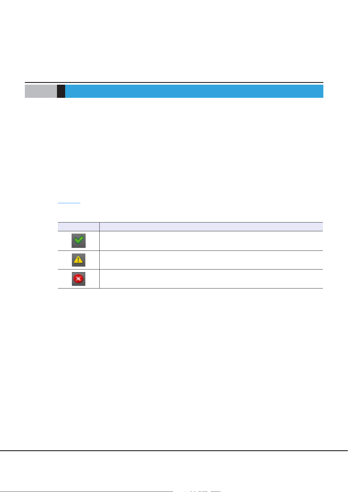
Table 2.1
Table 2.1 Status icons
shows the status icons that appear on the panels and the meaning of the icons.
LED Function
The green Status OK icon indicates that the library is fully operational and that no user interaction is
required.
The yellow exclamation point Status Warning icon indicates that user attention is necessary, but
that the device can still perform most operations.
The red X Status Error icon indicates that user intervention is required and that the device is not
capable of performing some operations.
18
FUJITSU Storage ETERNUS LT260 Tape Library User’s Guide -Panel Operation-
Copyright 2019 FUJITSU LIMITED P3AM-8802-09ENZ0
Page 19
Chapter 2 Operating the Library
2.1 Using the Operator Panel
2.1 Using the Operator Panel
The front panel has a power button, an LCD touch screen, and five LEDs. With the operator panel you can
monitor, configure, and operate most library functions from the front panel. To navigate the operator panel,
tap on the LCD touch screen.
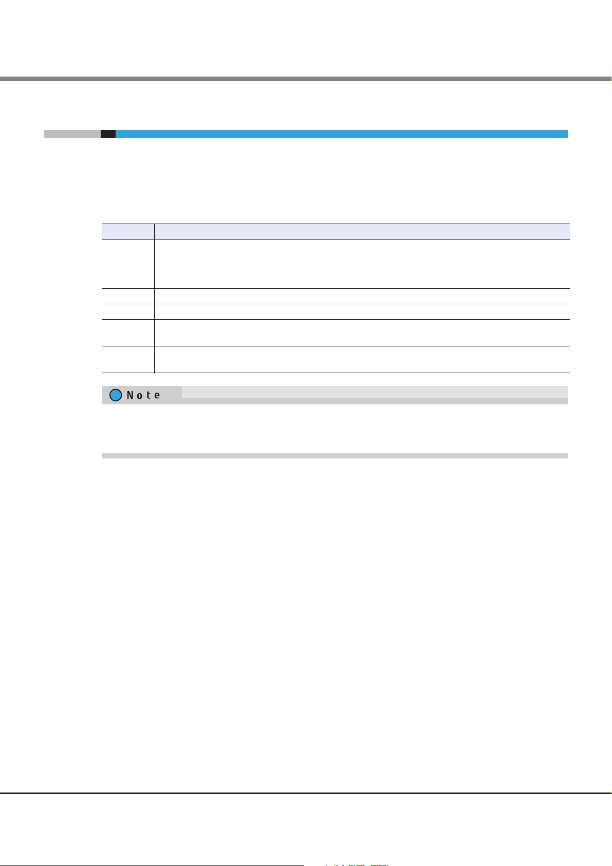
Table 2.2 Front panel LED indicators
LED Function
Blue when activated. The unit identification (UID) LEDs are controlled by the user through the operator
Module ID
Ready Green, steady when power is on, blinking with tape Ready drive or library robotic activity.
Clean Amber when a tape drive cleaning operation is recommended.
Attention
Error
panel and remote panel Maintenance > UID LED Control screen. The UIDs on the operator panel and back
panel UID are activated and deactivated together. The UIDs are helpful for locating the library in a data
center.
Amber if the library has detected a condition for which user attention is necessary, but that the library can
still perform most operations.
Amber if an unrecoverable tape drive or library error occurs. A corresponding error message is displayed
on the LCD screen. User intervention is required; the library is not capable of performing some operations.
The operator panel screen may be initialized if time elapses without logging in or during the logout process.
As a feature, the operator panel turns white for a few seconds during the initialization of the screen and then
login screen appears.
19
FUJITSU Storage ETERNUS LT260 Tape Library User’s Guide -Panel Operation-
Copyright 2019 FUJITSU LIMITED P3AM-8802-09ENZ0
Page 20
Chapter 2 Operating the Library
2.2 Using the Remote Panel
2.2 Using the Remote Panel
With the remote panel, you can monitor, configure, and operate most library functions from a web browser.
When possible, it is recommended that the remote panel be used as the primary library interface because
compared to the operations of the operator panel, the web interface provides access to additional features,
such as online help, and is easier to use. However, the remote panel is not required to use the product, except
to configure advanced features, such as SNMP, IPv6, encryption, and partitions.
Before using the remote panel, you must configure the library network settings and set the administrator
password with the operator panel. This can be done with the Initial Configuration Wizard. See "2.5.1
Initial Configuration Wizard" (page 27).
To start the remote panel, open the latest version of a supported web browser and enter the IP address of the
library in the browser’s address bar. Supported browsers include Internet Explorer (version 10 or later is recommended), Firefox, Chrome and Safari.
Using the
Check the online help in the remote panel for additional information. The help pages are updated with firmware updates and often contain up-to-date technical details that might not be contained in this document.
To access remote panel help, click the icon on the right side of the remote panel top banner.
20
FUJITSU Storage ETERNUS LT260 Tape Library User’s Guide -Panel Operation-
Copyright 2019 FUJITSU LIMITED P3AM-8802-09ENZ0
Page 21
Chapter 2 Operating the Library
Procedure
End of procedure
2.3 Logging into the Library
2.3 Logging into the Library
Figure 2.1 Login
1 Operator panel: If the operator panel screen saver is on, tap the screen.
Remote panel: Open a supported web browser and enter the IP address of the library in the
browser’s address bar.
2 Select the User.
3 If required, enter the Password.
4 Click Login.
The user levels are:
• user
The initial password is "std00001". The user account provides access to status information, but not
configuration, maintenance or operation functions. The administrator account can be used to set the user
account password, and allow or forbid the use of some of the operation functions by the user account.
Based on the firmware version, refer to "2.5.15
7.80 and Earlier)" (page 58), or "2.5.16 Configuring User Account Settings (for Firmware Versions 7.90 and
Later)" (page 60) for details.
• administrator
The administrator password is required to login as the administrator user. The same administrator password is used for the remote panel and operator panel. The initial administrator password is "adm00001".
The administrator user has access to all functionality except for the log configuration and Service features.
Configuring User Account Settings (for Firmware Versions
21
FUJITSU Storage ETERNUS LT260 Tape Library User’s Guide -Panel Operation-
Copyright 2019 FUJITSU LIMITED P3AM-8802-09ENZ0
Page 22
Chapter 2 Operating the Library
2.3 Logging into the Library
From a security perspective, changing the default password immediately after starting the library is recommended.
When logging in for the first time, change the password using the Initial Configuration Wizard or change the
password with the user account settings.
Refer to "2.5.1
(for Firmware Versions 7.80 and Earlier)" (page 58), or "2.5.16 Configuring User Account Settings (for
Firmware Versions 7.90 and Later)" (page 60) for details.
• service
Access to this user is by Service personnel only. The service password is set at the factory. The same service
password is used for the remote panel and operator panel. Both the administrator and service passwords
are required for a service person to enter the service area.
• security
In addition to the functions that are available when logged in as the administrative user, the key
management function can be set. After the Key Management Function Option is purchased, the setting for
the key management function is available.
The initial password is "security". However, this password can only be used to log in from the operator
panel.
After the initial password is changed on the operator panel, the password can then also be used to log in
from the remote panel.
Using the Initial Configuration Wizard" (page 27), "2.5.15 Configuring User Account Settings
Basically, only one user can log in to the library regardless of whether the user logs in from the remote panel
or operator panel.
If a user is currently logged in, a warning message appears. Select whether to continue the login process.
• Select Leave to stop the login process.
• Select Login to continue the login process and forcibly log the currently logged in user out.
As an exception, only the "user" user account can log in to the library regardless of whether other users are
logged in.
Note that if no operation is performed for a certain period of time, the user is forcibly logged out.
22
FUJITSU Storage ETERNUS LT260 Tape Library User’s Guide -Panel Operation-
Copyright 2019 FUJITSU LIMITED P3AM-8802-09ENZ0
Page 23
Chapter 2 Operating the Library
Top banner
Left pane
Center pane
Right pane
2.4 Using the Library Home Screen
2.4 Using the Library Home Screen
The library home screen is organized into the following regions:
• Top banner
Contains the home button and displays the overall status and information about the library and user.
• Left pane
Displays the library identity and module status.
• Center pane
Provides access to operate and configure the library and to view additional status information.
• Right pane (remote panel only)
Displays a log of recent events.
Figure 2.2 Home screen
23
FUJITSU Storage ETERNUS LT260 Tape Library User’s Guide -Panel Operation-
Copyright 2019 FUJITSU LIMITED P3AM-8802-09ENZ0
Page 24
Chapter 2 Operating the Library
2.4 Using the Library Home Screen
2.4.1 Top Banner Elements
• (Home Icon)
Returns to the library home screen.
• Library Health
An icon indicating the overall health status of the library
-
The green check mark Status OK icon indicates that all library components are fully operational and
that no user intervention is required.
-
The yellow triangle exclamation point Status Warning icon indicates that user attention is necessary,
but that the library can still perform most operations. Click the icon to display the event ticket log.
-
The red circle X Status Error icon indicates that user intervention is required and the library is not
capable of performing some operations. Click the icon to display the event ticket log.
• Status
The status of the library robotic
- Idle
The library robotic is ready to perform an action.
- Moving
The library robotic is moving a cartridge.
- Scanning
The library robotic is performing an inventory of cartridges.
- Offline
The robotic assembly is being used by the library or is disabled.
• Library Time & Date
Helpful when analyzing event logs and support tickets, and might be needed when contacting support.
• User
The user account for this session
• Logout
Logs out of this session.
•
Accesses online help.
2.4.2 Left Pane Elements
• Library Status
Overall library confirmation and status
- Serial #
The base module serial number
- Hostname
The library hostname
FUJITSU Storage ETERNUS LT260 Tape Library User’s Guide -Panel Operation-
24
Copyright 2019 FUJITSU LIMITED P3AM-8802-09ENZ0
Page 25
Chapter 2 Operating the Library
2.4 Using the Library Home Screen
- Network Configuration
The IP version (IPv4 or IPv6) and IP address
- Firmware
The library firmware version
• Module Status Overviews
A summary of each module’s configuration and health. Click or tap the module status area to select the
module.
- Module Health Icon
•
The green check mark Status OK icon indicates that the module and each of its components are fully
operational and that no user intervention is required.
•
The yellow triangle explanation point Status Warning icon indicates that user attention is necessary, but that the library can still perform most operations.
•
The red circle X Status Error icon indicates that user intervention is required and the module is not
capable of performing some operations.
- Module Number
Modules are numbered based on their location in the physical library. The bottom module is Module 1.
The base module is annotated with (Base).
- Tape Drive Status
The number of tape drives installed in the module and the health of each tape drive. Click or tap on the
tape drive to display the tape drive configuration and status information in the center pane.
• A black square indicates that the tape drive is fully operational and that no user intervention is
required.
• A yellow square indicates that user attention is necessary, but that the tape drive can still perform
most operations.
• A red square indicates that user intervention is required or the tape drive is not capable of perform-
ing some operations.
- Magazine Slot Usage
The number of cartridge slots available and the number in use.
- Tape Drive Operation Status
The current tape drive activity for each tape drive in the module. The tape drive operation status is only
displayed for the selected module.
• Write
The tape drive is performing a write operation.
• Read
The tape drive is performing a read operation.
• Idle
A cartridge is in the tape drive but the tape drive is not performing an operation.
• Empty
The tape drive is empty.
• Encrypt
The tape drive is writing encrypted data.
25
FUJITSU Storage ETERNUS LT260 Tape Library User’s Guide -Panel Operation-
Copyright 2019 FUJITSU LIMITED P3AM-8802-09ENZ0
Page 26

Chapter 2 Operating the Library
2.4 Using the Library Home Screen
2.4.3 Center Panel Elements
• Open Mailslot (Non-user account)
Click or tap to unlock the mailslot on the selected module. Mailslots must be enabled before the slots can
be used as mailslots. See "2.5.12
• Open Magazine (Non-user account)
Click or tap to unlock a magazine in the selected module. Only one magazine in the library can be open at
a time. See "2.7.3
• Configuration (Non-user account)
Click or tap to configure the library. See "2.5
• Maintenance (Non-user account)
Click or tap to access maintenance functions. See "2.6
• Operation (Non-user account)
Click or tap to access operation functions. See "2.7
• Status
Click or tap to access status information. See "2.8
Opening a Magazine" (page 102).
Enabling or Disabling Mailslots" (page 51).
Configuring the Library" (page 27).
Maintaining the Library" (page 82).
Operating the Library" (page 99).
Viewing Status Information" (page 106).
26
FUJITSU Storage ETERNUS LT260 Tape Library User’s Guide -Panel Operation-
Copyright 2019 FUJITSU LIMITED P3AM-8802-09ENZ0
Page 27
Chapter 2 Operating the Library
2.5 Configuring the Library
2.5 Configuring the Library
Click or tap [Configuration] in the home screen to access the library configuration function. From the list displayed in the center pane in the operator panel or the right pane in the remote panel, select the item to configure. Refer to "1.3
For items with a sub-menu, click or tap the item to expand the sub-menu.
2.5.1 Using the Initial Configuration Wizard
The wizard guides you through setting the administrator password, configuring the time zone, date and time,
and library network settings. When logging in to the remote panel for the first time, performing a configura-
tion using this function is recommended.
The items that can be configure by this function can also be configured individually. To configure an item
individually, refer to the following as required.
• Administrator password
"2.5.15
Configuring User Account Settings (for Firmware Versions 7.90 and Later)" (page 60)
• Timezone
"2.5.3.1
• Date and time
"2.5.3.2
• Library network settings
"2.5.8
Configuring User Account Settings (for Firmware Versions 7.80 and Earlier)" (page 58) or "2.5.16
Configuring the Library Network Settings" (page 42)
Menu Layout" (page 16) for the items.
Setting the Time Zone" (page 34)
Setting the Date and Time Format" (page 35)
27
FUJITSU Storage ETERNUS LT260 Tape Library User’s Guide -Panel Operation-
Copyright 2019 FUJITSU LIMITED P3AM-8802-09ENZ0
Page 28
Chapter 2 Operating the Library
Procedure
2.5 Configuring the Library
To configure the library, perform the following procedure.
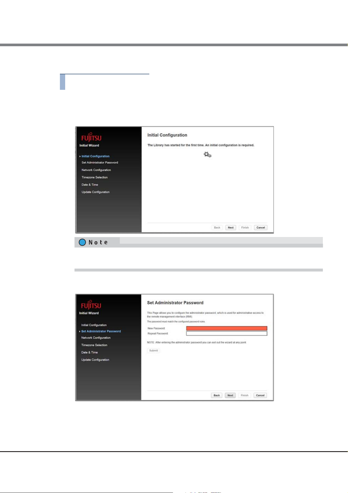
1 In the [Configuration > System] screen, click "Initial Configuration Wizard" in the right pane
to start the wizard.
2 Click [Next].
To skip the configuration, click [Next] without entering any information. To go back to the previous
item, click [Back]. To cancel the configuration, click [Cancel].
3 Set the administrator password.
Enter the password twice and click [Submit]. When the setting is completed, click [Next].
28
FUJITSU Storage ETERNUS LT260 Tape Library User’s Guide -Panel Operation-
Copyright 2019 FUJITSU LIMITED P3AM-8802-09ENZ0
Page 29
Chapter 2 Operating the Library
2.5 Configuring the Library
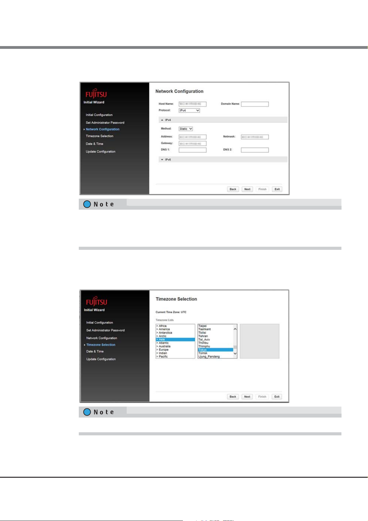
4 Configure the network settings.
Enter a value for the required items and then click [Next].
Enter values according to the selected [Protocol].
When directly entering an Internet address, select Static for [Method] and enter a value in each item.
When automatically obtaining an Internet address from a DHCP server, select DHCP (for IPv4) or Stateless (for IPv6).
5 Configure the timezone
Select a timezone location from [Timezone Lists]. For location names that start with ">", a
sub-menu is displayed in the right pane when selected and a more detailed location can be
selected. After selecting a timezone, click [Next].
For example, select [Asia > Tokyo] to set the timezone to Japan Standard Time.
29
FUJITSU Storage ETERNUS LT260 Tape Library User’s Guide -Panel Operation-
Copyright 2019 FUJITSU LIMITED P3AM-8802-09ENZ0
Page 30
Chapter 2 Operating the Library
End of procedure
2.5 Configuring the Library
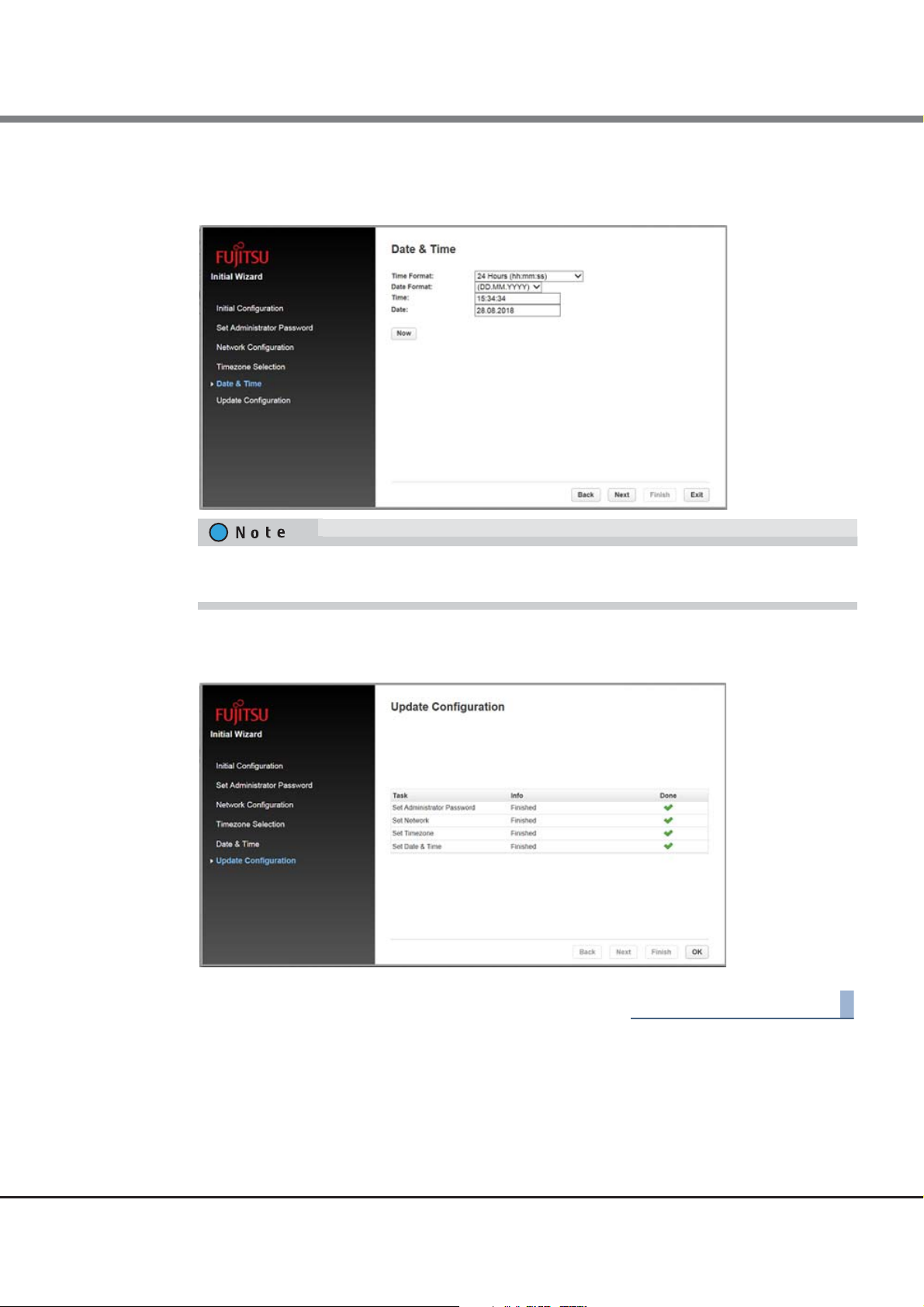
6 Configure the date and time.
Select a time format for [Time Format] and a date format for [Date Format], enter the date
and time, and then click [Next].
By pressing the [Now] button, the date and time are synchronized with the PC and automatically
entered.
7 Click [Finish].
8 Confirm the result of the configuration and click [OK] to complete the configuration.
30
FUJITSU Storage ETERNUS LT260 Tape Library User’s Guide -Panel Operation-
Copyright 2019 FUJITSU LIMITED P3AM-8802-09ENZ0
Page 31

Chapter 2 Operating the Library
2.5 Configuring the Library
2.5.2 Saving, Restoring and Resetting the Library Configuration
From the Configuration > System > Save/Restore Configuration screen you can save the library configuration
settings to a file, restore the settings, or reset the library configuration. The saved configuration database will
make it easier it recover the library configuration if you need to replace the base module or base module controller.
When the library is configured or set after purchasing the LT260 or when the library configuration or setting
is changed during operation, make sure to save the library configuration settings as a file. The saved library
configuration setting file can be restored in the library using the remote panel. Keep the latest library configuration setting file in a safe location. This file may be required for maintenance.
Figure 2.3 Save/Restore configuration
31
FUJITSU Storage ETERNUS LT260 Tape Library User’s Guide -Panel Operation-
Copyright 2019 FUJITSU LIMITED P3AM-8802-09ENZ0
Page 32

Chapter 2 Operating the Library
Procedure
End of procedure
Procedure
End of procedure
2.5 Configuring the Library
■ Saving the library configuration to a file
1 Navigate to the Configuration > System > Save/Restore Configuration screen as shown
above.
2 Under Save Configuration File, click Save.
3 When Download appears, click it and then select the destination location.
■ Restoring the library configuration from a file
If the Key Management Function Option is being used, the master key and the encryption key are deleted
when the device setting information is restored.
Because encrypted data will become unreadable if the master key and the encryption key are deleted, ask
the security administrator to export the master key and the encryption key in advance and store them in a
secure location.
Refer to "2.2 Backing Up the Setting Information" of "FUJITSU Storage ETERNUS LT260 Tape Library Key Management Function Option User's Guide" for details.
1 Navigate to the Configuration > System > Save/Restore Configuration screen.
2 Under Restore Configuration File, click Browse. Then select the location of the configuration
file.
3 Click Upload File & Restore.
If the library configuration is restored, the library is restarted.
32
FUJITSU Storage ETERNUS LT260 Tape Library User’s Guide -Panel Operation-
Copyright 2019 FUJITSU LIMITED P3AM-8802-09ENZ0
Page 33

Chapter 2 Operating the Library
2.5 Configuring the Library
■ Resetting the library configuration information
To reset the library configuration information to the default settings, click Reset Default Settings and select
Yes.
If the library configuration information is reset, the library is restarted.
■ Resetting the list of known drives and modules
To reset the list of known drives and modules, click Reset the List of Known Drives and Modules and select Yes.
Resetting the list of known drives and modules will cause the library to re-discover only the drives and
modules that are physically present. This operation will alter the list of element addresses reported to hosts
and will re-number the drives and modules. This operation cannot be undone. After the operation
completes, use one of the partition wizards to modify partitioning as needed.
■ Resetting hardware configuration
To reset the hardware configuration, click Reset Hardware Configuration and select Yes.
Resetting the Hardware Configuration will cause the library to re-discover the currently present hardware.
This operation cannot be undone. After the operation completes, use one of the partition wizards to modify
partitioning as needed.
33
FUJITSU Storage ETERNUS LT260 Tape Library User’s Guide -Panel Operation-
Copyright 2019 FUJITSU LIMITED P3AM-8802-09ENZ0
Page 34

Chapter 2 Operating the Library
Procedure
End of procedure
2.5 Configuring the Library
2.5.3 Configuring the Date and Time Format
To configure date and time format parameters and to use an SNTP server, from the Configuration area, navigate to the System > Date and Time Format screen.
The library does not adjust its time for daylight saving time; the time must be adjusted manually.
2.5.3.1 Setting the Time Zone
1 Click Time Zone.
A list of continents, countries, and regions is displayed. When an item proceeded with ">", for example
"> US", is selected, a submenu is displayed in the next column.
Figure 2.4 Time zone
2 Expand the time zone list, as necessary, until a location with the appropriate time zone is
visible. Select a location with the appropriate time zone.
For example, select [Asia > Tokyo] to set the timezone to Japan Standard Time.
3 Click Submit.
34
FUJITSU Storage ETERNUS LT260 Tape Library User’s Guide -Panel Operation-
Copyright 2019 FUJITSU LIMITED P3AM-8802-09ENZ0
Page 35

Chapter 2 Operating the Library
Procedure
End of procedure
2.5 Configuring the Library
2.5.3.2 Setting the Date and Time Format
1 Click Date/Time Format.
Figure 2.5 Date/Time format
2 Select a time format.
3 Select a date format:
For example, July 30, 2013 is displayed as:
• DD.MM.YYYY - 30.07.2013
• MM/DD/YYYY - 07/30/2013
• YYYY-MM-DD - 2013-07-30
4 Click Submit.
35
FUJITSU Storage ETERNUS LT260 Tape Library User’s Guide -Panel Operation-
Copyright 2019 FUJITSU LIMITED P3AM-8802-09ENZ0
Page 36

Chapter 2 Operating the Library
Procedure
End of procedure
2.5 Configuring the Library
2.5.3.3 Setting the Date and Time
1 Click Set Date/Time.
Figure 2.6 Set date/time
2 Enter time and date information.
Manual Input:
Enter time and date information directly.
Automatic Input:
Click Now. The time and date information is entered automatically by the synchronization to the
computer running the remote panel.
3 Click Submit.
36
FUJITSU Storage ETERNUS LT260 Tape Library User’s Guide -Panel Operation-
Copyright 2019 FUJITSU LIMITED P3AM-8802-09ENZ0
Page 37

Chapter 2 Operating the Library
Procedure
End of procedure
2.5 Configuring the Library
2.5.3.4 Enabling SNTP (Simple Network Time Protocol) Synchronization
The library must have network access to an SNTP server.
1 Click SNTP.
Figure 2.7 SNTP
2 Click SNTP Enabled.
3 Enter the SNTP server address.
4 Click Submit.
Synchronization to the SNTP server is executed every 8 hours. Depending on the time deviation, the synchronization mode (Step mode/Slew mode) is automatically selected.
37
FUJITSU Storage ETERNUS LT260 Tape Library User’s Guide -Panel Operation-
Copyright 2019 FUJITSU LIMITED P3AM-8802-09ENZ0
Page 38

Chapter 2 Operating the Library
2.5 Configuring the Library
2.5.4 Configuring Media Barcode Compatibility Checking
From the Configuration > System > Media Barcode Compatibility Check screen you can enable or disable the
barcode media ID check.
Figure 2.8 Media barcode compatibility check
When Barcode Media ID Restriction is enabled, the library will only allow appropriate tape cartridges to be
loaded into tape drives. The barcode media ID is the last two characters of the barcode. For example, an LTO6 labeled cartridge will not be allowed to move into an LTO-5 tape drive.
When disabled, the library will move any tape to any tape drive. If the cartridge is incompatible with the tape
drive, the library will display a message.
• It is strongly recommended that all cartridges have barcode labels with the correct media ID, and that the
Barcode Media ID Restriction is enabled.
• If a barcode label with an incorrect media ID is being used, the tape cartridge may be moved to an incom-
patible tape drive.
38
FUJITSU Storage ETERNUS LT260 Tape Library User’s Guide -Panel Operation-
Copyright 2019 FUJITSU LIMITED P3AM-8802-09ENZ0
Page 39

Chapter 2 Operating the Library
Procedure
End of procedure
2.5 Configuring the Library
2.5.5 Configuring Allow Unlabeled Media Setting
Although it is strongly recommended to use labeled media, the tape library is capable to detect cartridges
without barcode label within the inventory scan. This function enables the library to detect and use cartridges
unlabeled or difficult to read labels.
To enable detection of cartridges unlabeled or difficult to read labels navigate to Configuration > System >
Allow Unlabeled Media.
1 Set the checkbox.
2 Click Submit.
Figure 2.9 Allow unlabeled media
Using this option may increase the duration of the inventory time, thus it is strongly recommended to use
correctly labeled media!
39
FUJITSU Storage ETERNUS LT260 Tape Library User’s Guide -Panel Operation-
Copyright 2019 FUJITSU LIMITED P3AM-8802-09ENZ0
Page 40

Chapter 2 Operating the Library
Procedure
End of procedure
2.5 Configuring the Library
2.5.6 Configuring License Key Handing
When adding a license key, navigate to the System > License Key Handling screen.
Figure 2.10 License key handing
1 Enter license key.
The license key needs to have a length of 15 characters.
2 Click Add License.
40
FUJITSU Storage ETERNUS LT260 Tape Library User’s Guide -Panel Operation-
Copyright 2019 FUJITSU LIMITED P3AM-8802-09ENZ0
Page 41

Chapter 2 Operating the Library
Procedure
End of procedure
2.5 Configuring the Library
2.5.7 Configuring the RMI Timeout Setting (for Firmware Versions 7.80 and Earlier)
To set the timeout for the remote panel, navigate to the System > RMI Timeout screen.
1 Select timeout value (5 or 30 minutes).
2 Click Submit.
Figure 2.11 RMI timeout
For firmware versions 7.90 and later, this setting has been integrated in the [Configuration > Web Management] menu.
To set the remote panel timeout for firmware versions 7.90 and later, refer to "2.5.18.5
Timeout Period of the Remote Panel (for Firmware Versions 7.90 and Later)" (page 79).
Setting the Session
41
FUJITSU Storage ETERNUS LT260 Tape Library User’s Guide -Panel Operation-
Copyright 2019 FUJITSU LIMITED P3AM-8802-09ENZ0
Page 42

Chapter 2 Operating the Library
Procedure
End of procedure
2.5 Configuring the Library
2.5.8 Configuring the Library Network Settings
From the Configuration > Network screen you can configure the library network settings.
Figure 2.12 Network setting
1 Navigate to the Configuration > Network screen.
2 Configure or update the Host Name and Domain Name. The remote panel URL is <
Name
>.<
Domain Name
>.
Host
3 Select the Internet protocol to use for the library.
4 Configure the settings for the selected Internet protocol.
To have the library obtain an Internet address from a DHCP server, select the DHCP or Stateless method.
5 Click Submit.
Use "Reset internal IP Range" in case that the network conflict is occurred. This function should not be used in
other case.
Refer to "User's Guide -Installation & Operation- 3.1 Powering On/Off" about how to use the function.
42
FUJITSU Storage ETERNUS LT260 Tape Library User’s Guide -Panel Operation-
Copyright 2019 FUJITSU LIMITED P3AM-8802-09ENZ0
Page 43

Chapter 2 Operating the Library
2.5 Configuring the Library
2.5.9 Configuring the SNMP
This operation can be executed from only remote panel operation.
Use the Configuration > Network Management screen to enable and configure SNMP (Simple Network
Management Protocol), which allows applications to manage the device. The library supports both SNMP
configuration and SNMP traps.
The monitoring server can receive SNMP traps if the "ETERNUS SF Storage Cruiser" management software is set
up on the server. Refer to the ETERNUS SF Storage Cruiser manuals for details.
Table 2.3 Management software
Software name Supported function
FUJITSU Storage ETERNUS SF Storage Cruiser SAN management, fault monitoring
For information about the versions of ETERNUS SF Storage Cruiser that support the LT260, contact our sales
representative.
Figure 2.13 SNMP
43
FUJITSU Storage ETERNUS LT260 Tape Library User’s Guide -Panel Operation-
Copyright 2019 FUJITSU LIMITED P3AM-8802-09ENZ0
Page 44

Chapter 2 Operating the Library
2.5 Configuring the Library
• SNMP Enabled
When checked, the library can be managed by computers listed in the SNMP Target IP Addresses field.
• Community Name
A string used to match the SNMP management station and library. It must be set to the same name on
both the management station and the library. The default community name is
• Notification Level
The types of events for which the library should send.
- Inactive
No events are sent.
- Critical
Only critical events are sent.
- + Warnings
Only critical and warning events are sent.
- + Configuration
Only critical, warning, and configuration events are sent.
- + Information
All events are sent.
public
.
• SNMP Targets
List of configured SNMP targets.
The following are the optional settings for SNMPv3. When using SNMPv3, perform these settings.
• Limit all library SNMP communication to SNMPv3
If the checkbox is selected, the usable SNMP version is limited to SNMPv3. If this setting is enabled, the
SNMP Targets set with SNMPv1 and SNMPv2 are deleted. When the checkbox is selected, a confirmation
screen is displayed. Click [Yes] to proceed.
• SNMPv3 Security Level
SNMPv3 security level for SNMP communication
- noAuthNoPriv
Authentication and encryption are not used for SNMP communication.
- AuthNoPriv
Authentication is used for SNMP communication.
- AuthPriv
Authentication and encryption are used for SNMP communication.
• Authentication User Name
The username used for communication using SNMPv3. Required when using SNMPv3.
• Authentication Password
A password with eight or more characters used for SNMP communication authentication. Required when
AuthNoPriv and AuthPriv are selected for SNMPv3 Security Level.
44
FUJITSU Storage ETERNUS LT260 Tape Library User’s Guide -Panel Operation-
Copyright 2019 FUJITSU LIMITED P3AM-8802-09ENZ0
Page 45

Chapter 2 Operating the Library
Procedure
End of procedure
Procedure
End of procedure
2.5 Configuring the Library
■ To add an SNMP target or edit information for an SNMP target
1 Click Edit for the appropriate SNMP target. When adding an SNMP target, click Edit next to a
target without an IP/Hostname.
2 Enter the target IP address or hostname.
3 Enter the port.
4 Select the SNMP version.
5 Enter the SNMP community string for the target.
6 Enter the optional setting for SNMPv3. (When using SNMPv3)
7 Click Submit.
■ To delete an SNMP target
1 Click Delete for the target to be deleted.
2 Click Submit.
45
FUJITSU Storage ETERNUS LT260 Tape Library User’s Guide -Panel Operation-
Copyright 2019 FUJITSU LIMITED P3AM-8802-09ENZ0
Page 46

Chapter 2 Operating the Library
Procedure
End of procedure
2.5 Configuring the Library
■ To clear SNMPv3 Options
1 Click Clear SNMPv3 Options.
To confirm that you want to clear the SNMPv3 Options, click Yes.
Figure 2.14 SNMPv3
2 Click the [Yes] button.
46
FUJITSU Storage ETERNUS LT260 Tape Library User’s Guide -Panel Operation-
Copyright 2019 FUJITSU LIMITED P3AM-8802-09ENZ0
Page 47

Chapter 2 Operating the Library
2.5 Configuring the Library
2.5.10 Configuring the SMTP
This operation can be executed from only remote panel operation.
From the Configuration > Network Management > SMTP screen you can enable SMTP (Simple Mail Transfer
Protocol) functionality and configure E-mail notification of library events. The library must have network
access to an SMTP server.
Figure 2.15 SMTP
• SMTP Enabled
Check to enable SMTP. When checked, the remaining configurations are active.
• Notification Level
The types of events for which the library should send E-mail
- Inactive
No events are sent.
- Critical
Only critical events are sent.
- + Warnings
Only critical and warning events are sent.
- + Configuration
Only critical, warning, and configuration events are sent.
- + Information
All events are sent.
• SMTP Server
Hostname or IP address of the SMTP server
47
FUJITSU Storage ETERNUS LT260 Tape Library User’s Guide -Panel Operation-
Copyright 2019 FUJITSU LIMITED P3AM-8802-09ENZ0
Page 48

Chapter 2 Operating the Library
2.5 Configuring the Library
• Security
Security protocol for accessing the SMTP server
- None
- SSL
- TLS
• SMTP Port
SMTP server port. The default port for the selected protocol will be selected. You can choose one of the
default ports or configure a custom port.
• To Email Address
The address to receive the reported events (for example firstname.lastname@example.com). Only one
email address can be configured.
• Mailer Name
Name of the sender of the E-mail
• Email Subject
Subject line for the E-mail message
• Emailer Address
Return address to use for the E-mail message
• Authentication Required
When checked, a username and password are required to access the SMTP server.
• Username
User account for logging into the SMTP server when authentication is required.
• Password
Password associated with the Username when authentication is required.
48
FUJITSU Storage ETERNUS LT260 Tape Library User’s Guide -Panel Operation-
Copyright 2019 FUJITSU LIMITED P3AM-8802-09ENZ0
Page 49

Chapter 2 Operating the Library
2.5 Configuring the Library
2.5.11 Configuring Tape Drives
From the Configuration > Drives screen you can see and modify the tape drive configuration.
Figure 2.16 Tape drive settings
• Tape drive number
Tape drives are numbered from the bottom of the library up beginning with one. The tape drive currently
hosting the SCSI communication for the library is designated with (LUN).
• Serial number
The serial number assigned to the tape drive by the library. This serial number is reported to host applications. The serial number cannot be modified.
This is not the serial number assigned to the tape drive by the manufacturer; the serial number assigned
by the manufacturer is shown in Manufacturer S/N.
• LTO generation
- LTO 5
Ultrium 3000, Ultrium 3280
- LTO 6
Ultrium Tape Drive, Ultrium 6250
- LTO 7
Ultrium Tape Drive
- LTO 8
Ultrium Tape Drive
49
FUJITSU Storage ETERNUS LT260 Tape Library User’s Guide -Panel Operation-
Copyright 2019 FUJITSU LIMITED P3AM-8802-09ENZ0
Page 50

Chapter 2 Operating the Library
2.5 Configuring the Library
• Tape drive form factor
- HH
Half height
• Tape drive interface
- FC
Fibre Channel
- SAS
Serial Attached SCSI
• (Modified)
When present indicates that a setting has been changed. To apply the changes, click Submit. To reset all
changed fields to their previously saved values, click Undo.
• Pwr
Indicates whether the tape drive is currently powered on or off.
• Firmware
The version of firmware currently installed on the tape drive.
• Manufacturer S/N
The serial number assigned to the tape drive when it was manufactured. Use this serial number when
working with your Service.
• Power On
Checked when the tape drive is powered on.
Always power off a tape drive before removing it from the library or moving it to a new location within the
library.
• Port X configuration (FC only)
Tape drive port configuration.
- Speed
The currently selected speed. The default is Automatic.
- Port Type
• Automatic
• Loop
Enables selection of the Addressing Mode.
• Fabric
- Addressing Mode
When Port Type is set to Loop, Addressing Mode can be set to Soft, Hard, or Hard Autoselect.
- Loop ID/ALPA
When Addressing Mode is set to Hard, you can choose an ALPA address from the drop down list.
50
FUJITSU Storage ETERNUS LT260 Tape Library User’s Guide -Panel Operation-
Copyright 2019 FUJITSU LIMITED P3AM-8802-09ENZ0
Page 51

Chapter 2 Operating the Library
Procedure
End of procedure
2.5 Configuring the Library
■ To modify the configuration of one or more tape drives
1 Modify any of the configurable values.
2 Click Submit.
To configure the number of barcode characters to report to the host application and whether to report them
from the left or right end of the label, use either the Basic Partition Wizard or Expert Partition Wizard. See
"2.5.13.1
55).
Using the Basic Partition Wizard" (page 53) or "2.5.13.2 Using the Expert Partition Wizard" (page
2.5.12 Enabling or Disabling Mailslots
The Configuration > Mailslot screen lists each of the mailslots and shows whether each is enabled or disabled.
To change the state, click the button for the mailslot and then click Submit. Slots not enabled as mailslots are
available as storage slots.
Figure 2.17 Enabling or disabling mailslots
Do not change the mailslot setting (enable or disable) while the backup software is in use. If a change is
required, stop the backup software before performing any changes.
51
FUJITSU Storage ETERNUS LT260 Tape Library User’s Guide -Panel Operation-
Copyright 2019 FUJITSU LIMITED P3AM-8802-09ENZ0
Page 52

Chapter 2 Operating the Library
Procedure
End of procedure
2.5 Configuring the Library
The mailslot and magazine automatic re-lock duration can be selected.
1 Selection duration: 30 seconds (default) or 5 minutes.
2 Click Submit.
Figure 2.18 Setting re-lock time
2.5.13 Configuring Library Partitions
This operation can be executed from only remote panel operation.
The library has a flexible partitioning scheme with a few key constraints:
• The license option is necessary to create more than 2 partitions.
• Each partition must have at least one tape drive. One tape drive in each partition will host the library LUN
for the partition.
• The maximum number of partitions is 20.
• Magazine slots are allocated in five-slot groups.
• Mailslots must be enabled for a module before they can be allocated to a partition.
A partition does not need to have a mailslot. If a partition does not have a mailslot, the magazine must be
accessed to import or export cartridges. Opening a magazine takes the library off line.
Although the mailslot magazine is shared between partitions, the mailslot elements are assigned individually to partitions.
52
FUJITSU Storage ETERNUS LT260 Tape Library User’s Guide -Panel Operation-
Copyright 2019 FUJITSU LIMITED P3AM-8802-09ENZ0
Page 53

Chapter 2 Operating the Library
Procedure
2.5 Configuring the Library
Wizards guide you through the partition configuration process. The wizards are only accessible from the
remote panel.
• Basic Partition Wizard
You specify the number of partitions and the wizard removes the current partition configuration and
assigns the tape drives and storage slots as evenly as possible to the partitions. Any extra tape drives or
slots are assigned to the first partition.
Use the Basic Partition Wizard to configure partitions that will have similar resources or to configure the
number of barcode characters to report to the host application and whether to report them from the left or
right end of the label for a library with a single partition.
• Expert Partition Wizard
You add or remove partitions from the current partitions configuration and then edit each partition configuration to add or remove library resources.
Use the Expert Partition Wizard to configure partitions that will have different resources or to adjust
resource assignments for existing partitions or those created with the Basic Partition Wizard.
• The library will go off line while partitions are being configured. Ensure that all host operations are idle
before running a partition wizard.
• To use backup software, leave the automatic cleaning function disabled (default setting). Enabling the
setting causes a conflict error between the automatic cleaning function and the cleaning function of the
backup software.
For operations with the LTFS option, the automatic cleaning function can be enabled. Refer to "3.8 Cleaning the Tape Drive" in "FUJITSU Storage ETERNUS LT series Tape Libraries LTFS Option User's Guide" for
details.
2.5.13.1 Using the Basic Partition Wizard
1 Click Configuration > Partition > Basic Wizard to start the wizard.
The Information screen displays the existing partitions, which will be deleted by the wizard.
2 Click Proceed.
3 Click Next.
The Create Partition Scheme screen displays the number of slots, mailslots, tape drives, and
maximum available partitions for the library.
If you want to enable or disable the mailslots, Cancel out of the wizard and update the mailslot configuration before configuring partitioning.
4 Select the number of partitions.
53
FUJITSU Storage ETERNUS LT260 Tape Library User’s Guide -Panel Operation-
Copyright 2019 FUJITSU LIMITED P3AM-8802-09ENZ0
Page 54

Chapter 2 Operating the Library
End of procedure
2.5 Configuring the Library
5 Select the number of barcode characters reported to the host application.
This option provides interchange compatibility with libraries with more limited barcode reading capabilities. The maximum length is 15 and the default is 8. This configuration will apply to all partitions.
The industry standard length for LTO barcode labels is eight characters. Barcode labels longer than
eight characters might scan incorrectly, particularly if they are not high quality labels.
6 Select whether to report the barcode characters from the left or right end of the barcode
label to the host application when reporting fewer than the maximum number of characters.
For example, when reporting only six characters of the barcode label "12345678", if alignment is left,
the device will report 123456. If alignment is right, the device will report 345678. The default is left.
Click Next.
7 For operations with the backup software, the automatic cleaning function of the tape drive
must not be used. Leave the Auto Clean checkbox unselected.
For operations with the LTFS option, the automatic cleaning function can be enabled. Refer to "3.8
Cleaning the Tape Drive" in "FUJITSU Storage ETERNUS LT series Tape Libraries LTFS Option User's
Guide" for details.
8 Click Next.
9 The Finish Configuration screen displays the proposed allocation of library resources into
partitions.
■ To update the configuration, click Back.
■ To have the wizard configure partition as shown, click Finish.
After the wizard reconfigures the partition, the library will come on line automatically.
■ To exit the wizard, click Cancel or Exit.
You can use the Expert Partition Wizard to adjust the allocation of resources after creating the partitions with
the Basic Partition Wizard.
54
FUJITSU Storage ETERNUS LT260 Tape Library User’s Guide -Panel Operation-
Copyright 2019 FUJITSU LIMITED P3AM-8802-09ENZ0
Page 55

Chapter 2 Operating the Library
Procedure
2.5 Configuring the Library
2.5.13.2 Using the Expert Partition Wizard
Use the wizard to configure one partition at a time.
If you want to enable or disable the mailslots, Cancel out of the wizard and update the mailslot configuration
before configuring partitioning.
■ To add/modify a partition
1 Click Configuration > Partition > Expert Wizard to start the wizard.
The Create Partition Scheme screen lists the current partitions, if any, and the free resources.
2 To add a partition, click Add.
The Add button will only be active if there are available resources. If there are no available resources,
either edit a partition and release resources from it or remove a partition that contains extra
resources.
3 Click Next.
4 Enter a partition name in "Partition Name".
5 In "Barcode Label Length Reported To Host", select the number of barcode characters
reported to the host application.
This option provides interchange compatibility with libraries with more limited barcode reading capabilities. The maximum length is 15 and the default is 8. This configuration will apply to all partitions.
The industry standard length for LTO barcode labels is eight characters. Barcode labels longer than
eight characters might scan incorrectly, particularly if they are not high quality labels.
6 In "Barcode Label Alignment Reported To Host", select whether to report the barcode charac-
ters from the left end or right end of the barcode label to the host application when reporting fewer than the maximum number of characters.
For example, when reporting only six characters of the barcode label "12345678", if alignment is left,
the device will report 123456. If alignment is right, the device will report 345678. The default is left.
55
FUJITSU Storage ETERNUS LT260 Tape Library User’s Guide -Panel Operation-
Copyright 2019 FUJITSU LIMITED P3AM-8802-09ENZ0
Page 56

Chapter 2 Operating the Library
End of procedure
Procedure
End of procedure
2.5 Configuring the Library
7 When enabling the key management function for partitions, select the [Encryption Mode]
checkbox (only when the key management function option is used).
This setting can only be changed by the security administrator account.
As an exception, administrator accounts that are granted privileges by the security administrator can
change this setting. For details, refer to "2.1.3.2 Setting the Key Management Function (Firmware
Version 7.90 or Later)" in "FUJITSU Storage ETERNUS LT260 Tape Library Key Management Function
Option User's Guide".
8 Click Next.
9 In the Assign Storage Slots screen, use the >> and << buttons to assign slots to the new par-
tition and then click Next.
10 In the Assign Mail Slots screen, use the >> and << buttons to assign mailslots to the new
partition and then click Next.
Individual mailslot elements cannot be shared between partitions. Importing or exporting cartridges in
a partition without an assigned mailslot will require magazine access, which will take the library off
line.
11 In the Assign Drives screen, use the >> and << buttons to assign tape drives to the new par-
tition and then click Next.
12 If the partition has multiple tape drives, select the tape drive that will host the SCSI commu-
nication for the partition and then click Next.
The lowest numbered tape drive in the partition is the default.
13 Verify the partition configuration and then click Finish.
After the wizard reconfigures the partition, the library will come on line automatically.
■ To remove a partition
1 Select the partition, click Remove, and then click Next.
2 Verify that you want to remove the partition and then click Finish.
After the wizard removes the partition, the library will come on line automatically.
When deleting a partition that has the key management function enabled, perform it with the Security role.
The relevant partition cannot be deleted with the Administrator role.
56
FUJITSU Storage ETERNUS LT260 Tape Library User’s Guide -Panel Operation-
Copyright 2019 FUJITSU LIMITED P3AM-8802-09ENZ0
Page 57

Chapter 2 Operating the Library
2.5 Configuring the Library
2.5.14 Configuring Key Management Function
After logging in with the security account, the Configuration > Encryption screen can be selected. For the
default library state, the hardware encryption function of the tape drive is set to be used according to the
backup software. To use the hardware encryption function of a tape drive with a single library, the Key Management Function Option is required.
When using the Key Management Function Option, refer to "FUJITSU Storage ETERNUS LT260 Tape Library Key
Management Function Option User's Guide".
57
FUJITSU Storage ETERNUS LT260 Tape Library User’s Guide -Panel Operation-
Copyright 2019 FUJITSU LIMITED P3AM-8802-09ENZ0
Page 58

Chapter 2 Operating the Library
2.5 Configuring the Library
2.5.15 Configuring User Account Settings (for Firmware Versions 7.80 and Earlier)
From the Configuration > User Accounts screen, you can set the password for the user or administrator
accounts.
Select the user and then enter the new password twice. The password must contain 8-16 characters, which can
include upper and lowercase letters, numbers, and special characters.
For firmware versions 7.90 and later, the settings related to remote panel access have been integrated in the
[Configuration > Web Management] menu. When performing a configuration, refer to "2.5.18
the Access Management Setting to the Remote Panel" (page 68).
In addition, when performing user account settings with firmware versions 7.90 and later, refer to "2.5.16
Configuring User Account Settings (for Firmware Versions 7.90 and Later)" (page 60).
Figure 2.19 User accounts settings
Configuring
• user
The user account allows access to library status information and does not allow access to configuration,
maintenance, or operation features. The initial password is "std00001". Setting a user password restricts
access to status information to only those who know the user password.
• administrator
Setting an administrator password provides access to the administrator functions with the remote panel or
operator panel, and restricts access to the administrator functions to only those who know the administrator password. The initial administrator password is "adm00001".
58
FUJITSU Storage ETERNUS LT260 Tape Library User’s Guide -Panel Operation-
Copyright 2019 FUJITSU LIMITED P3AM-8802-09ENZ0
Page 59

Chapter 2 Operating the Library
2.5 Configuring the Library
• security
In addition to the functions that are available when logged in as the administrative user, the key management function can be set. After the Key Management Function Option is purchased, the setting for the key
management function is available.
The initial password is "security". Before the password is changed, all the management functions can be
used without limitations from the operator panel, but they cannot be used from the remote panel. After
the security administrator password is changed on the operator panel, the password can be set from both
panels.
■ Restricted RMI login
The administrator has the possibility to set login restrictions for administrator and security login. To enable
the restriction mode, select the "Restricted Remote Management Interface (RMI) Login:" checkbox. If the
restriction mode is enabled the administrator and the security are not allowed to login via the remote panel.
The administrator has to disable the restriction mode by logging into the operator panel.
Only the administrator is allowed to set and reset the restricted the remote panel login.
■ Allow magazine and mailslot access
The administrator can give users access permission to magazines by selecting the "Allow magazine access by
the "user" user account:" checkbox.
The administrator can give users access permission to mailslots by selecting the "Allow mailslot access by the
"user" user account:" checkbox.
59
FUJITSU Storage ETERNUS LT260 Tape Library User’s Guide -Panel Operation-
Copyright 2019 FUJITSU LIMITED P3AM-8802-09ENZ0
Page 60

Chapter 2 Operating the Library
2.5 Configuring the Library
2.5.16 Configuring User Account Settings (for Firmware Versions 7.90 and Later)
From the Configuration > User Accounts > Local User Accounts screen, you can add accounts, change roles, and
configure user accounts such as the password.
Figure 2.20 User account settings
In the Configuration > User Accounts > Local User Accounts screen, a list of configurable accounts among those
who are logged in are displayed. The displayed contents are as follows.
• Name
Account name
• User Role
Account type
- User
The user account allows access to library status information and does not allow access to configuration,
maintenance, or operation features. The initial password is "std00001". Setting a user password
restricts access to status information to only those who know the user password.
- Administrator
An administrator account provides access to almost all the administrator functions of the library from
the remote panel or operator panel. By setting a password, access to the administrator functions is
restricted to only users who know the administrator password.
The default administrator password of the library is "adm00001".
- Security
In addition to the functions that the Administrator account can use, the security administrator can
enable/disable SSL and set the key management function. The key management function can be used
by purchasing the Key Management Function Option.
The default password is "security".
• Status
Login state of the account.
- Connected
The account is logged in.
- Disconnected
The account is not logged in.
- Disconnected/Locked
The account is locked and cannot be used to log in.
60
FUJITSU Storage ETERNUS LT260 Tape Library User’s Guide -Panel Operation-
Copyright 2019 FUJITSU LIMITED P3AM-8802-09ENZ0
Page 61

Chapter 2 Operating the Library
2.5 Configuring the Library
• Last Activity
The last day and time the account logged in.
The configurable account type differs depending on the account used to log in. The Administrator account
can configure the "User" and "Administrator" accounts and the Security Administrator account can configure
the "Security" account. In addition, for the password setting, passwords that do not satisfy the specified
requirements cannot be used. This requirement can be changed to meet your security requirements. For
details, refer to "2.5.17
66).
Configuring Password Requirements (for Firmware Versions 7.90 and Later)" (page
61
FUJITSU Storage ETERNUS LT260 Tape Library User’s Guide -Panel Operation-
Copyright 2019 FUJITSU LIMITED P3AM-8802-09ENZ0
Page 62

Chapter 2 Operating the Library
Procedure
End of procedure
2.5 Configuring the Library
2.5.16.1 Adding an Account
1 Click [Add User+].
2 Enter an account name to add in [Name] and select an account type for "Role" in the expanded input
window.
3 Enter the password twice.
4 Click [Add].
Figure 2.21 Adding an Account
The password set here is for the initial login. For newly added accounts, the password must be changed by
the user the first time they log in. Perform the password setting as instructed.
For accounts whose User Role is Administrator or Security, most of the library functions can be used. From a
security perspective, add a limited number of accounts and issue those accounts to trusted users only.
62
FUJITSU Storage ETERNUS LT260 Tape Library User’s Guide -Panel Operation-
Copyright 2019 FUJITSU LIMITED P3AM-8802-09ENZ0
Page 63

Chapter 2 Operating the Library
Procedure
End of procedure
2.5 Configuring the Library
2.5.16.2 Changing the Account Password
1 Click an account to change its password.
2 From [Actions], select [Modify Password].
3 Enter the new password twice in the expanded input window.
4 Click [Modify].
Figure 2.22 Changing the Account Password
When changing the password of a locked account, the lock is released when the password is changed. For
details about locked accounts, refer to "2.5.17
7.90 and Later)" (page 66).
If the user account whose password is to be changed and the account used to change it is different (for
example, when the administrator changes the password of a user account), the user must set a password
again when logging in for the first time after the password is changed. Follow the instruction to set the password.
Configuring Password Requirements (for Firmware Versions
63
FUJITSU Storage ETERNUS LT260 Tape Library User’s Guide -Panel Operation-
Copyright 2019 FUJITSU LIMITED P3AM-8802-09ENZ0
Page 64

Chapter 2 Operating the Library
Procedure
End of procedure
2.5 Configuring the Library
2.5.16.3 Changing the User Account Role
By giving permission to operate the magazine/mailslot, tape cartridges can be removed from the library
even with a User account.
For security purposes, give permission only to reliable users.
1 From [Actions], select [Modify Role Permissions].
2 Select the role to change in the expanded input window.
• Allow magazine access by the "User role"
Allow the User account to operate the magazine.
• Allow mailslot access by the "User role"
Allow the User account to operate the mailslot.
3 Click [Modify].
Figure 2.23 Changing the User Account Role
64
FUJITSU Storage ETERNUS LT260 Tape Library User’s Guide -Panel Operation-
Copyright 2019 FUJITSU LIMITED P3AM-8802-09ENZ0
Page 65

Chapter 2 Operating the Library
Procedure
End of procedure
2.5 Configuring the Library
2.5.16.4 Deleting an Account
1 Select the account to delete.
2 From [Actions], select [Remove User].
3 In the expanded confirmation window, click [Yes].
Figure 2.24 Deleting an account
The only accounts that can be deleted are the ones that have been added. The default accounts (user,
administrator, security) cannot be deleted.
65
FUJITSU Storage ETERNUS LT260 Tape Library User’s Guide -Panel Operation-
Copyright 2019 FUJITSU LIMITED P3AM-8802-09ENZ0
Page 66

Chapter 2 Operating the Library
2.5 Configuring the Library
2.5.17 Configuring Password Requirements (for Firmware Versions 7.90 and Later)
This operation can only be executed from the remote panel.
The settings requirements used when the account password is set can be configured in the [Configuration >
User Accounts > User Accounts Settings] screen.
The requirements that can be configured are as follows. After selecting a requirement, click [Submit] to reflect
the setting.
• Minimum Number Of Characters
Sets the minimum number of characters for the password. The range of characters that can be set is 8 to
20.
• Minimum Number Of Upper Case Alphabetic Characters (A-Z)
Sets the minimum number of uppercase letters. The range of uppercase letters that can be set is 0 to 3.
• Minimum Number Of Lower Case Alphabetic Characters (a-z)
Sets the minimum number of lowercase letters. The range of lowercase letters that can be set is 0 to 3.
• Minimum Number Of Numeric Characters (0-9)
Sets the minimum number of numeric characters. The range of numeric characters that can be set is 0 to 3.
• Minimum Number Of Special Characters (!@#$%^&*()_+-={}|[]\;':"<>?,./)
Sets the minimum number of special characters. The range of special characters that can be set is 0 to 3.
• Maximum Number Of Identical Consecutive Characters
Sets the maximum number of consecutive identical characters that can be used. The range of consecutive
identical characters that can be set is 1 to 3. If Unlimited is selected, there is no limit.
• Maximum Number Of Failed Logins Before Password Is Locked
Sets the maximum number of failed login attempts before the account is locked. The range of login
attempts that can be set is 1 to 10. If Unlimited is selected, there is no limit.
• Maximum Number Of Days Before Password Must Be Changed
Sets the maximum number of days the same password can be used. The password must be changed within
the period. The range of days that can be set is up to 365. If Unlimited is selected, there is no limit.
• Number Of Password Changes Before An Old Password Can Be Used Again
Sets the number of password changes before a previously used password can be reused. The range of password changes that can be set is up to 6. If 0 is set, there is no limit.
66
FUJITSU Storage ETERNUS LT260 Tape Library User’s Guide -Panel Operation-
Copyright 2019 FUJITSU LIMITED P3AM-8802-09ENZ0
Page 67

Chapter 2 Operating the Library
CAUTION
Do
2.5 Configuring the Library
• If "Maximum Number Of Failed Logins Before Password Is Locked" is not set
to Unlimited, the account is locked if the number of failed login attempts
reaches the set value.
Locked accounts cannot log in to the remote panel, so make sure to enter
the correct password.
If an account is locked or cannot be login into due to a lost password, take
the following action for each account:
- user
Contact the Administrator and request a new password.
- administrator
A one-time password must be issued. Contact the maintenance engineer.
- security
Because the security account is the highest ranking security account,
the password cannot be reissued. If the security account cannot log in,
a factory reset is required.
Save the setting information and export the encryption key before contacting your maintenance engineer.
Figure 2.25 Password setting requirements
67
FUJITSU Storage ETERNUS LT260 Tape Library User’s Guide -Panel Operation-
Copyright 2019 FUJITSU LIMITED P3AM-8802-09ENZ0
Page 68

Chapter 2 Operating the Library
2.5 Configuring the Library
2.5.18 Configuring the Access Management Setting to the Remote Panel
Configure the settings for access management to the remote panel on the [Configuration > Web Management
screen.
• The functions related to certificates can only be used in the remote panel.
• For firmware versions 7.90 and later, the setting items related to access management of the remote panel
have been revised and more detailed settings are available to further enhance the security. For details,
check the setting method for each item. The items added for 7.90 and later are listed with "for firmware
versions 7.90 and later".
Figure 2.26 Access management setting to the remote panel (for firmware versions 7.80 and earlier)
68
FUJITSU Storage ETERNUS LT260 Tape Library User’s Guide -Panel Operation-
Copyright 2019 FUJITSU LIMITED P3AM-8802-09ENZ0
Page 69

Chapter 2 Operating the Library
2.5 Configuring the Library
Figure 2.27 Access management setting to the remote panel (for firmware versions 7.90 and later)
69
FUJITSU Storage ETERNUS LT260 Tape Library User’s Guide -Panel Operation-
Copyright 2019 FUJITSU LIMITED P3AM-8802-09ENZ0
Page 70

Chapter 2 Operating the Library
2.5 Configuring the Library
2.5.18.1 Enabling SSL
Access to the remote panel using Secure Socket Layer (SSL) encrypted communication can be enabled or disabled in [Secure Communications] on the [Configuration > Web Management] screen. The default is disable.
For firmware versions 7.80 and earlier, the [Secure Communications] item is not available.
Direct operation is available on the [Configuration > Web Management] screen.
To enable SSL, select the checkbox and click [Submit].
If SSL is enabled, https must be used to connect to the remote panel.
SSH is used for maintenance work. It cannot be used by the customer.
Figure 2.28 Enabling the SSL setting
70
FUJITSU Storage ETERNUS LT260 Tape Library User’s Guide -Panel Operation-
Copyright 2019 FUJITSU LIMITED P3AM-8802-09ENZ0
Page 71

Chapter 2 Operating the Library
2.5 Configuring the Library
2.5.18.2 Certificate Settings (for Firmware Version 7.90 and Later)
In [Certificate Settings] on the [Configuration > Web Management] screen, enable SSL and select the self
signed certificate to use for https connections.
• Use Self Signed Certificate
Uses the default self signed certificate of the library.
• Use Custom Certificate
Uses the self signed certificate created by the user. If a self signed certificate is not created, this item cannot be selected.
For information about creating a self signed certificate, refer to "2.5.18.3
(page 72).
Figure 2.29 Certificate settings
Creating a Self Signed Certificate"
71
FUJITSU Storage ETERNUS LT260 Tape Library User’s Guide -Panel Operation-
Copyright 2019 FUJITSU LIMITED P3AM-8802-09ENZ0
Page 72

Chapter 2 Operating the Library
Procedure
2.5 Configuring the Library
2.5.18.3 Creating a Self Signed Certificate
Create a self signed certificate for the LT260 in [Create Custom Certificate] on the [Configuration > Web Management screen.
For firmware versions 7.80 and earlier, the [Create Custom Certificate] item is not available.
Direct operation is available on the [Configuration > Web Management] screen.
• Set the RMI timeout value to 30 minutes. For information about setting the RMI timeout value, refer to
"2.5.7
Configuring the RMI Timeout Setting (for Firmware Versions 7.80 and Earlier)" (page 41) for firm-
ware versions 7.80 and earlier, and "2.5.18.5
Firmware Versions 7.90 and Later)" (page 79) for 7.90 and later.
• For https connections to RMI using the created self signed certificate, the signed CA public certificate (root
certificate) in the LT260 self signed certificate must be saved to the trusted Root Certification Authorities
store of the client computer.
Setting the Session Timeout Period of the Remote Panel (for
1 On the [Create Custom Certificate] screen, click [Start Certificate Wizard].
Figure 2.30 Self signed certificate creation screen
72
FUJITSU Storage ETERNUS LT260 Tape Library User’s Guide -Panel Operation-
Copyright 2019 FUJITSU LIMITED P3AM-8802-09ENZ0
Page 73

Chapter 2 Operating the Library
2.5 Configuring the Library
2 Start the wizard and when the [Information] screen is displayed, click [Next].
Figure 2.31 Information screen
73
FUJITSU Storage ETERNUS LT260 Tape Library User’s Guide -Panel Operation-
Copyright 2019 FUJITSU LIMITED P3AM-8802-09ENZ0
Page 74

Chapter 2 Operating the Library
2.5 Configuring the Library
3 On the [Certificate Signing Request] screen (Figure 2.32), enter the appropriate data in the
seven fields and generate a Certificate Sign Request (CSR).
For the data to be entered, contact the security administrator. When all seven fields are
entered, [Generate CSR] becomes selectable. Click [Generate CSR] to generate the CSR.
Figure 2.32 Certificate Signing Request screen 1
4 Copy the entire contents of the generated CSR displayed in the "Certificate Sign Request:"
field.
5 Create a Signed Certificate from the copied CSR.
Contact the security administrator for information about creating a Signed Certificate.
74
FUJITSU Storage ETERNUS LT260 Tape Library User’s Guide -Panel Operation-
Copyright 2019 FUJITSU LIMITED P3AM-8802-09ENZ0
Page 75

Chapter 2 Operating the Library
2.5 Configuring the Library
6 Click [Next].
If the Signed Certificate is created from the Certificate Signing Request, make sure to complete this
procedure up to Step 7
the CSR information generated in Step 3
it cannot be used again and the process must be started again from Step 3
Figure 2.33 Certificate Signing Request screen 2
within 30 minutes. After 30 minutes, the RMI timeout setting is activated and
becomes invalid. Once the CSR information becomes invalid,
.
75
FUJITSU Storage ETERNUS LT260 Tape Library User’s Guide -Panel Operation-
Copyright 2019 FUJITSU LIMITED P3AM-8802-09ENZ0
Page 76

Chapter 2 Operating the Library
2.5 Configuring the Library
7 Paste the Signed Certificate in the "Signed Certificate:" field and click [Next].
Figure 2.34 Signed Certificate screen
76
FUJITSU Storage ETERNUS LT260 Tape Library User’s Guide -Panel Operation-
Copyright 2019 FUJITSU LIMITED P3AM-8802-09ENZ0
Page 77

Chapter 2 Operating the Library
End of procedure
2.5 Configuring the Library
8 When the application process of the self signed certificate is displayed on the [Finish]
screen (Figure 2.35
Part of the [Apply Certificate And Reload Page] task is executed when [Finish] is clicked.
Figure 2.35 Finish screen
), click [Finish].
77
FUJITSU Storage ETERNUS LT260 Tape Library User’s Guide -Panel Operation-
Copyright 2019 FUJITSU LIMITED P3AM-8802-09ENZ0
Page 78

Chapter 2 Operating the Library
Procedure
End of procedure
Procedure
End of procedure
2.5 Configuring the Library
2.5.18.4 Backing Up and Restoring the Self Signed Certificate (for Firmware Versions 7.90 and Later)
The self signed certificate created for the LT260 can be backed up and restored using [Backup Custom Certificate] and [Restore Custom Certificate] on the [Configuration > Web Management] screen.
■ Backing up the self signed certificate
1 Click [Backup Custom Certificate].
Figure 2.36 Backing up the self-signed certificate
2 Specify the save destination and save the self signed certificate as a file.
■ Restoring the self signed certificate
1 In [Restore Custom Certificate], click [Browse] to select the location of the saved self signed
certificate.
Figure 2.37 Restoring the self signed certificate
2 Click [Restore Custom Certificate].
78
FUJITSU Storage ETERNUS LT260 Tape Library User’s Guide -Panel Operation-
Copyright 2019 FUJITSU LIMITED P3AM-8802-09ENZ0
Page 79

Chapter 2 Operating the Library
2.5 Configuring the Library
2.5.18.5 Setting the Session Timeout Period of the Remote Panel (for Firmware Versions 7.90 and
Later)
Set the session timeout period of the remote panel from [Session Timeout] on the [Configuration > Web Management] screen.
To change the session timeout period, select a time from the [Select how many minutes a user should stay
logged in] dialog box and click [Submit]. The available selections are "5 min" and "30 min".
Figure 2.38 Setting the session timeout
2.5.18.6 Setting Login Session Locking Function (for Firmware Versions 7.90 and Later)
Enable or disable session locking to the remote panel and operator panel from [OCP/RMI Session Locking] on
the [Configuration > Web Management] screen. The default is disable. To enable the session locking function,
select the checkbox and click [Submit].
If the login session locking function is enabled, logins to the remote panel and operator panel are not allowed
until the currently logged in user is logged out.
Figure 2.39 Setting login session locking function
79
FUJITSU Storage ETERNUS LT260 Tape Library User’s Guide -Panel Operation-
Copyright 2019 FUJITSU LIMITED P3AM-8802-09ENZ0
Page 80

Chapter 2 Operating the Library
2.5 Configuring the Library
■ When the login session locking function is disabled
If a login is performed while another user is logged in, a warning message is displayed indicating that another
user is logged in. If [Login] is clicked, the logged in user is forcibly logged out and a login can be performed.
Figure 2.40 Disabled login session locking function
■ When the login session locking function is enabled
If a login is performed while another user is logged in, a warning message is displayed indicating that another
user is logged in. A login cannot be performed until the currently logged in user logs out.
Figure 2.41 Enabled login session locking function
80
FUJITSU Storage ETERNUS LT260 Tape Library User’s Guide -Panel Operation-
Copyright 2019 FUJITSU LIMITED P3AM-8802-09ENZ0
Page 81

Chapter 2 Operating the Library
2.5 Configuring the Library
2.5.18.7 Remote Panel Restriction Setting (for Firmware Versions 7.90 and Later)
Enable the remote panel restriction setting from [Restricted Remote Management Interface (RMI) Login] on
the [Configuration > Web Management] screen. The default is disable. To enable the remote panel restriction
setting, select the checkbox and click [Submit].
If the remote panel restriction setting is enabled, only the User account can log in to the remote panel. However, the library status information can be checked by logging in with the User account.
Other than using the remote panel for a status check, all other operations are restricted. Execute library
operations from the operator panel. The same function also removes the restriction.
Figure 2.42 Remote panel restriction setting
81
FUJITSU Storage ETERNUS LT260 Tape Library User’s Guide -Panel Operation-
Copyright 2019 FUJITSU LIMITED P3AM-8802-09ENZ0
Page 82

Chapter 2 Operating the Library
2.6 Maintaining the Library
2.6 Maintaining the Library
Click or tap [Maintenance] in the home screen to access the library maintenance function. From the list displayed in the center pane in the operator panel or the right pane in the remote panel, select the item to configure. Refer to "1.3
For items with a sub-menu, click or tap the item to expand the sub-menu.
2.6.1 Library Tests
2.6.1.1 System Test
The system test exercises overall library functionality by moving the tape cartridges within the library.
• During each cycle the library will move a tape cartridge from a configured slot to an empty slot and then
return it to its original slot. You can set the number of cycles for the test. If the test is canceled, the library
will return the cartridge to its original slot.
Menu Layout" (page 16) for the items.
• The library will not move cleaning cartridges during the test.
• The test operates over the whole library and does not take into account partition configuration.
• During the test the library is off line.
To run the system test, navigate to the Maintenance > Library Tests > System Test screen, select the number of
cycles and then click Start Test.
Figure 2.43 System test
82
FUJITSU Storage ETERNUS LT260 Tape Library User’s Guide -Panel Operation-
Copyright 2019 FUJITSU LIMITED P3AM-8802-09ENZ0
Page 83

Chapter 2 Operating the Library
2.6 Maintaining the Library
2.6.1.2 Slot to Slot Test
The slot to slot test randomly exchanges cartridges between slots to verify that the library is operating correctly. At the end of the test the cartridges are NOT returned to their original slots. If a tape cartridge is moved
to an incompatible tape drive, the tape drive will reject the tape cartridge.
The test can move cartridges between partitions.
To run the slot to slot test, navigate to the Maintenance > Library Tests > Slot to Slot Test screen, select the
number of cycles and click Start Test.
Figure 2.44 Slot to slot test
83
FUJITSU Storage ETERNUS LT260 Tape Library User’s Guide -Panel Operation-
Copyright 2019 FUJITSU LIMITED P3AM-8802-09ENZ0
Page 84

Chapter 2 Operating the Library
2.6 Maintaining the Library
2.6.1.3 Element to Element Test
The element to element test moves a selected cartridge to a selected slot or tape drive, and then returns it to
the original slot. You can select the number of times to move the selected cartridge to the destination location
and back.
The element to element test is intended to show that the library is operating correctly. To diagnose problems
with the robotic assembly or verify that it has been correctly replaced, use the robotic test.
Figure 2.45 Element to element test
84
FUJITSU Storage ETERNUS LT260 Tape Library User’s Guide -Panel Operation-
Copyright 2019 FUJITSU LIMITED P3AM-8802-09ENZ0
Page 85

Chapter 2 Operating the Library
Procedure
End of procedure
2.6 Maintaining the Library
■ To run the element test
1 Navigate to the Maintenance > Library Tests > Element to Element Test screen.
2 Select a cartridge from the Source Elements list.
To select from a subset of the cartridges:
2-1 Click Filter On.
2-2 Enter characters into the search box and then click Search.
The Source Elements list is updated to only include cartridges with a barcode label including the
search characters.
3 Select a location from the Destination Elements list.
4 Select the number of cycles.
5 Click Start Test.
85
FUJITSU Storage ETERNUS LT260 Tape Library User’s Guide -Panel Operation-
Copyright 2019 FUJITSU LIMITED P3AM-8802-09ENZ0
Page 86

Chapter 2 Operating the Library
2.6 Maintaining the Library
2.6.1.4 Position Test
The position test moves the robotic assembly vertically between two elements. The number of movements
can be specified.
This test does not move cartridges.
Figure 2.46 Position test
86
FUJITSU Storage ETERNUS LT260 Tape Library User’s Guide -Panel Operation-
Copyright 2019 FUJITSU LIMITED P3AM-8802-09ENZ0
Page 87

Chapter 2 Operating the Library
Procedure
End of procedure
2.6 Maintaining the Library
■ To run the position test
1 Navigate to the Maintenance > Library Tests > Position Test screen.
2 Select a cell from the Source Elements list.
To select from a subset of the cell:
(1)Click Filter On.
(2)Enter characters into the search box and then click Search.
The Source Elements list is updated to only include cartridges with a barcode label including the
search characters.
3 Select a destination cell from the Destination Elements list.
4 Select the number of cycles.
5 Click Start Test.
87
FUJITSU Storage ETERNUS LT260 Tape Library User’s Guide -Panel Operation-
Copyright 2019 FUJITSU LIMITED P3AM-8802-09ENZ0
Page 88

Chapter 2 Operating the Library
2.6 Maintaining the Library
2.6.1.5 Wellness Test
• The wellness test exercises a general health check on the library functionality by running the following
partial tests:
- Basic Hardware Review
- Robotics Initialization Test
- Barcode Scanning Test
- Magazine/Mailslot Unlock Motor Test
- Move Media Test
• Running the test requires at least one drive and one tape carting in the library.
• After the test has been started the Stop Test button is active. Clicking the button will abort the wellness test
but not before the current partial test has been completed.
• The test operates over the whole library and does not take into account partition configuration.
• During the test the library is off line.
• The Info column notifies the user about the status and result of each partial test.
To run the wellness test, navigate to the Maintenance > Library Tests > Wellness Test screen, and then click
Start Test.
Figure 2.47 Wellness test
88
FUJITSU Storage ETERNUS LT260 Tape Library User’s Guide -Panel Operation-
Copyright 2019 FUJITSU LIMITED P3AM-8802-09ENZ0
Page 89

Chapter 2 Operating the Library
2.6 Maintaining the Library
2.6.1.6 Robotic Test
The robotic test performs a full inventory and exercises all robotic assembly movements and sensors.
To run the robotic test, navigate to the Maintenance > Library Tests > Robotic Test screen, then click Start Test.
Figure 2.48 Robotic test
2.6.1.7 Operator Panel Test and Calibration
To perform a test or maintenance operation for the operator panel, navigate to the Maintenance > Library
Tests > Operator Panel Test screen, select the operation, and then click Start. Follow the instructions on the
screen.
Figure 2.49 OCP test
• LED test
Illuminates each of the front panel LEDs.
• Touch panel calibration test
Allows you to calibrate the front panel touch screen.
• OCP Reboot
Restarts the operator panel.
89
FUJITSU Storage ETERNUS LT260 Tape Library User’s Guide -Panel Operation-
Copyright 2019 FUJITSU LIMITED P3AM-8802-09ENZ0
Page 90

Chapter 2 Operating the Library
2.6 Maintaining the Library
2.6.2 Viewing Log Files
● Operate from the operator panel
To view the library log files, navigate to the Maintenance > View Logs screen and then select one of the
logs.
● Operate from the remote panel
To view the library log files, navigate to the Maintenance > Logs and Traces > View Logs screen and then
select one of the logs.
The available logs are as follows. In addition, for firmware versions 7.90 and later, all the following logs are
shown at once if [Show All] is selected.
• Event Ticket Log
Records library error and warning events.
• Information Log
Records library information warnings.
• Configuration Log
Records configuration changes.
If [Close all open tickets] is clicked, all the logs that are being displayed become hidden.
After the [Include closed tickets] checkbox is selected, the logs that were hidden by clicking [Close Ticket] or
[Close all open tickets] are also displayed.
If the Attention LED is on, clicking [Close ticket] or [Close all open tickets] turns the Attention LED off.
Do not click [Clear log]. If [Clear log] is clicked, all the required information for a maintenance is cleared.
Figure 2.50 View logs
90
FUJITSU Storage ETERNUS LT260 Tape Library User’s Guide -Panel Operation-
Copyright 2019 FUJITSU LIMITED P3AM-8802-09ENZ0
Page 91

Chapter 2 Operating the Library
2.6 Maintaining the Library
The log entries are displayed in order of most recent to oldest. The log entries contain a date and time code,
event code, severity, component identifier and event details.
The format for the date and time is:
• DD.MM.YYYY
The date displayed as Day.Month.Year
• HH.MM.SS
The time displayed as Hour.Minute.Second
After the log that is being displayed is clicked, the detailed information is displayed.
Figure 2.51 Detailed view example for logs
DD.MM.YYYY HH.MM.SS
After [Close Ticket] is clicked, this log is hidden.
After [Close] is clicked, the detailed view screen is closed.
91
FUJITSU Storage ETERNUS LT260 Tape Library User’s Guide -Panel Operation-
Copyright 2019 FUJITSU LIMITED P3AM-8802-09ENZ0
Page 92

Chapter 2 Operating the Library
2.6 Maintaining the Library
2.6.3 Managing System Firmware
The firmware version currently installed on the library is displayed in the library status area on the Home
page. You update the library firmware from the Maintenance > Software Upgrades > System Firmware screen.
Figure 2.52 Upgrades system firmware
To update library firmware from the remote panel, click Browse and select the firmware file from the local
computer.
When you update the library firmware, the library will update the firmware of the expansion modules to a
compatible version.
92
FUJITSU Storage ETERNUS LT260 Tape Library User’s Guide -Panel Operation-
Copyright 2019 FUJITSU LIMITED P3AM-8802-09ENZ0
Page 93

Chapter 2 Operating the Library
Procedure
End of procedure
2.6 Maintaining the Library
2.6.4 Managing Drive Firmware
Drive firmware can be updated on multiple tape drives of the same type at the same time. Drive firmware can
only be updated from the remote panel. Each tape drive will only accept appropriate firmware.
To see the firmware version currently installed in the tape drives, navigate to the Status > Drive Status screen.
Figure 2.53 Upgrades drive firmware
■ To update drive firmware from the remote panel
1 Navigate to the Maintenance > Software Upgrades > Drive Firmware screen. The tape drives
are organized by drive type.
2 Select the type of tape drive to update and then select one or more of the tape drives from
the expanded list.
3 Click Browse, and then select the file from the local computer.
4 Click Submit.
93
FUJITSU Storage ETERNUS LT260 Tape Library User’s Guide -Panel Operation-
Copyright 2019 FUJITSU LIMITED P3AM-8802-09ENZ0
Page 94

Chapter 2 Operating the Library
Procedure
2.6 Maintaining the Library
2.6.5 Downloading Drive Logs
From the Maintenance > Download Drive Logs screen, logs can be downloaded from any tape drive.
Customers may be asked by maintenance personnel to acquire logs for troubleshooting.
Figure 2.54 Download drive logs
1 Select a tape drive to download the log.
The following items are displayed in the list of drive logs.
• Drive
The tape drive number. Tape drives are numbered starting with one from the physical bottom of the
library to the top.
• Type
The drive form factor (half height) and interface
• Firmware
The current drive firmware version
• Serial
The tape drive serial number
• Unit
The module containing the tape drive
• Partition
The logical library (or partition) associated with the tape drive
94
FUJITSU Storage ETERNUS LT260 Tape Library User’s Guide -Panel Operation-
Copyright 2019 FUJITSU LIMITED P3AM-8802-09ENZ0
Page 95

Chapter 2 Operating the Library
End of procedure
2.6 Maintaining the Library
2 Select a log to download.
• Current Log (*1)
Creates and saves a new log from the tape drive.
• Log From Last Unload (*1)
Saves the log that was automatically created after the last cartridge was unloaded from the tape
drive.
• Regular Dump (*2)
Saves the tape drive error information that is stored in the nonvolatile memory. The errors that
occur just before saving may not be saved.
• Forced Dump (*2)
Saves the error information up to the point when the Dump was executed. Since the size of the
memory that is used for recording is small, if a considerable amount of time elapses after the error
occurred, there may be cases when the error information is not saved.
*1: Displayed if the model name of the tape drive is in the following list:
LT26ASHE, LT26ASHL (LTO-5 SAS HH drive option)
LT26AFHE, LT26AFHL (LTO-5 FC HH drive option)
LT26ASJE, LT26ASJL (LTO-6 SAS HH drive option)
LT26AFJE, LT26AFJL (LTO-6 FC HH drive option)
*2: Displayed if the model name of the tape drive is in the following list:
LT26BSKE, LT26BSKL (LTO-6 SAS HH drive option -I)
LT26BFKE, LT26BFKL (LTO-6 FC HH drive option -I)
LT26BSME, LT26BSML (LTO-7 SAS HH drive option -I)
LT26BFME, LT26BFML (LTO-7 FC HH drive option -I)
LT26BSNE, LT26BSNL (LTO-8 SAS HH drive option -I)
LT26BFNE, LT26BFNL (LTO-8 FC HH drive option -I)
3 Check the tape drive, and then click Save.
95
FUJITSU Storage ETERNUS LT260 Tape Library User’s Guide -Panel Operation-
Copyright 2019 FUJITSU LIMITED P3AM-8802-09ENZ0
Page 96

Chapter 2 Operating the Library
2.6 Maintaining the Library
2.6.6 Downloading Log and Trace Files
This operation can be executed from only remote panel operation.
Figure 2.55 Download logs and traces
To download the library log and trace files from the remote panel, navigate to the Maintenance > Logs and
Traces > Download Logs and Traces screen and then click Save.
Customers may be asked by maintenance personnel to acquire logs for troubleshooting.
2.6.7 Rebooting the Library
From the Maintenance > System Reboot screen, click Reboot.
Figure 2.56 Rebooting the library
96
FUJITSU Storage ETERNUS LT260 Tape Library User’s Guide -Panel Operation-
Copyright 2019 FUJITSU LIMITED P3AM-8802-09ENZ0
Page 97

Chapter 2 Operating the Library
Procedure
End of procedure
2.6 Maintaining the Library
2.6.8 Tape Drive Reboot
From the Maintenance > Drive Reboot screen, you can reboot the tape drives.
Only one tape drive can be selected for reboot.
1 Select the tape drive you want to reboot.
Figure 2.57 Tape drive reboot
2 Click Yes on the dialog popup to start the reboot process.
97
FUJITSU Storage ETERNUS LT260 Tape Library User’s Guide -Panel Operation-
Copyright 2019 FUJITSU LIMITED P3AM-8802-09ENZ0
Page 98

Chapter 2 Operating the Library
2.6 Maintaining the Library
2.6.9 Controlling the UID LED
The UID LEDs are a pair of blue LEDs — one on the operator panel and the other on the base module controller.
The UID LEDs are useful for identifying the library in a data center. The UID LEDs are operated synchronously
and controlled by the user. From the Maintenance > UID LED Control screen you can see whether the LEDs are
lit, and toggle the status.
Figure 2.58 UID LED control
2.6.10 Moving the Robotic to the Base Module
Before extending a module from the rack, the robotic assembly must return to its park position in the base
module. Under normal circumstances, when the library is powered off using the front power button the robot
automatically parks and locks into the base module behind the operator panel. After powering off the library
and before proceeding with extending a module from the rack, look inside the base module window to verify
that the robotic assembly is behind the operator panel.
If the library did not move the robotic assembly to its park position, you can do so from the Maintenance >
Move Robotic to Base Module screen.
Figure 2.59 Move robotic to base module
98
FUJITSU Storage ETERNUS LT260 Tape Library User’s Guide -Panel Operation-
Copyright 2019 FUJITSU LIMITED P3AM-8802-09ENZ0
Page 99

Chapter 2 Operating the Library
2.7 Operating the Library
2.7 Operating the Library
Click or tap [Operation] in the home screen to use the library operation function. From the list displayed in the
center pane in the operator panel or the right pane in the remote panel, select the item to configure. Refer to
"1.3
Menu Layout" (page 16) for the items.
For items with a sub-menu, click or tap the item to expand the sub-menu.
2.7.1 Moving Media
From the Operation > Move Media screen you can move a tape cartridge located in a source element to an
available destination element within the same partition.
Figure 2.60 Move media
• Source Elements
Tape drives, enabled mailslots, and storage slots that contain a tape cartridge
• Destination Elements
Tape drives, enabled mailslots, and storage slots that do not contain a tape cartridge
Tape drives are listed at the top of each element list and listed in the order of their drive numbers.
Tape drives are numbered from the physical bottom of the library starting with Drive (1).
m.s
Slots are listed in the order of the slot numbers. Slots are numbered
s is the slot within the module.
, where m is the module number and
99
FUJITSU Storage ETERNUS LT260 Tape Library User’s Guide -Panel Operation-
Copyright 2019 FUJITSU LIMITED P3AM-8802-09ENZ0
Page 100

Chapter 2 Operating the Library
Procedure
End of procedure
2.7 Operating the Library
■ Filtering Based on Barcode
This function can be used from only remote panel operation.
To see a subset of the cartridges in the library, enter some or all of the barcode label characters in the search
area and click Search. The Source Element list updates to display only the cartridges with labels that include
the characters in the search box.
To perform a different search or display all of the available cartridges, click Barcode Filter Off.
■ Moving a Cartridge
1 Select the cartridge from Source Elements.
2 Select the destination location from Destination Elements.
3 Click Submit.
2.7.2 Opening the Mailslot
From the Operation > Open Mailslot screen you can see the status and unlock any enabled mailslots in the
library.
This function can be accessed directly from [Open Mailslot] on the home screen without going through the
[Operation] screen.
Be careful not to remove the wrong tape cartridge or install a tape cartridge in the wrong partition slot.
For this reason, check the following points before opening the mailslot.
• Number and position of the mailslot to open
• Number and position of the slot to load or unload the tape cartridge
• Slot allocation of each partition
For details on how to check the above information, refer to "2.8.3
111) and "2.8.4 Partition Map Graphical View" (page 113).
Using Inventory Graphical View" (page
100
FUJITSU Storage ETERNUS LT260 Tape Library User’s Guide -Panel Operation-
Copyright 2019 FUJITSU LIMITED P3AM-8802-09ENZ0
 Loading...