

Page 1

FUJITSU SEMICONDUCTOR
SUPPORT SYSTEM
SS01-71060-1E
DSU-FR EMULATOR
LQFP-64P HEADER TYPE 2
MB2198-304
OPERATION MANUAL
Page 2
PREFACE
Thank you for purchasing the LQFP-64P*1 header type 2 (MB2198-304) for the DSU-FR emulator.
This product is used together with the BGA-660P adapter for the DSU-FR emulator (MB2198-
300)*
user system that uses a MB91460 series Fujitsu FR*
This manual describes how to use the LQFP-64P header type 2 for the DSU-FR emulator. Please read
the manual carefully before using. Please contact your Fujitsu sales or support representative for details on which production and evaluation MCU models can be used with this product.
*1 : The lead pitch of package (FPT-64P-M23) is 0.65mm and the body size is 14mm × 14mm.
*2 : Referred to as the “adapter”
*3 : Referred to as the “emulator”
*4 : Referred to as the “DSU cable”
*5 : FR is an abbreviation of FUJITSU RISC CONTROLLER and is a product of Fujitsu Limited.
■ Handling and usage
The handling and use of this product and notes regarding safety use are included in the hardware
manual of the DSU-FR family emulator.
Follow the instructions in for the use of this product.
2
to connect the DSU-FR emulator (MB2198-01)*3 and DSU-FR cable (MB2198-10)*4 to a
• DSU-FR EMULATOR MB2198-01 HARDWARE MANUAL
• DSU-FR EMULATOR DSU-FR CABLE MB2198-10 OPERATION MANUAL
• DSU-FR EMULATOR BGA-660P ADAPTER MB2198-300 OPERATION MANUAL
4
microcontroller (LQFP-64P)*5.
■ Caution of the products described in this manual
The following precautions apply to the product described in this manual.
CAUTION
Cuts
Damage
Damage
The wrong use of a device will give an injury and may cause malfunction on customers system.
This product has parts with sharp points that are exposed. Do not touch edge of
the product with your bare hands. There is a possibility that it may be injured.
When connect the header board to the user system, correctly position the index
mark (▲) on the NQPACK mounted on the user system with the index mark (▲)
on the header board, otherwise the emulator system and user system might be
damaged.
When mounting a mass production MCU, correctly position pin 1, otherwise the
mass production MCU and user system might be damaged.
i
Page 3

• The contents of this document are subject to change without notice.
Customers are advised to consult with FUJITSU sales representatives before ordering.
• The information, such as descriptions of function and application circuit examples, in this document are presented solely for the purpose of reference to show examples of operations and uses of FUJITSU semiconductor device; FUJITSU
does not warrant proper operation of the device with respect to use based on such information. When you develop
equipment incorporating the device based on such information, you must assume any responsibility arising out of such
use of the information. FUJITSU assumes no liability for any damages whatsoever arising out of the use of the information.
• Any information in this document, including descriptions of function and schematic diagrams, shall not be construed
as license of the use or exercise of any intellectual property right, such as patent right or copyright, or any other right
of FUJITSU or any third party or does FUJITSU warrant non-infringement of any third-party’s intellectual property
right or other right by using such information. FUJITSU assumes no liability for any infringement of the intellectual
property rights or other rights of third parties which would result from the use of information contained herein.
• The products described in this document are designed, developed and manufactured as contemplated for general use,
including without limitation, ordinary industrial use, general office use, personal use, and household use, but are not
designed, developed and manufactured as contemplated (1) for use accompanying fatal risks or dangers that, unless
extremely high safety is secured, could have a serious effect to the public, and could lead directly to death, personal
injury, severe physical damage or other loss (i.e., nuclear reaction control in nuclear facility, aircraft flight control, air
traffic control, mass transport control, medical life support system, missile launch control in weapon system), or (2)
for use requiring extremely high reliability (i.e., submersible repeater and artificial satellite).
Please note that FUJITSU will not be liable against you and/or any third party for any claims or damages arising in
connection with above-mentioned uses of the products.
• Any semiconductor devices have an inherent chance of failure. You must protect against injury, damage or loss from
such failures by incorporating safety design measures into your facility and equipment such as redundancy, fire protection, and prevention of over-current levels and other abnormal operating conditions.
• If any products described in this document represent goods or technologies subject to certain restrictions on export under the Foreign Exchange and Foreign Trade Law of Japan, the prior authorization by Japanese government will be
required for export of those products from Japan.
Copyright ©2007 FUJITSU LIMITED All rights reserved
ii
Page 4

1. Checking the Delivered Product
Before using the MB2198-304, confirm that the following components are included in the box:
• LQFP-64P header board*
1
: 1
• Screws for securing the header board (M2 × 10mm, 0.4mm pitch) : 4
• Washer s : 4
• NQPACK064SB*
• HQPACK064SB140*
2
3
: 1
: 1
• Operation manual (Japanese version) : 1
• Operation manual (English version, this manual) : 1
*1 : The YQPACK064SB is mounted on the header board (Tokyo Eletech Corporation, referred to
as the “YQPACK”).
*2 : The IC socket (manufactured by Tokyo Eletech Corporation, referred to as “NQPACK”). This
socket is supplied with a special screwdriver and 2 guide pins. Additionally, the relatively high
reliability NQPACK064SB-SL (Tokyo Eletech Corporation, sold separately) can be used by
preparing screw holes on the user system board for mounting the socket. For more information,
contact Tokyo Eletech Corporation.
*3 : The IC socket cover (manufactured by Tokyo Eletech Corporation, and referred to as “HQ-
PACK”). This cover includes 4 screws for securing HQPACK (M2 × 6mm, 0.4mm pitch).
This product is used as an emulator system by combining with an optional emulator, DSU cable and
adapter.
Consult a sales or support representative from Fujitsu Limited for details on the adapter and emulator
for this product.
2. Handling Precautions
■ Handling precautions
The header board is precision-manufactured to improve dimensional accuracy and to ensure reliable
contact. The header is therefore sensitive to mechanical shock. To ensure correct use of the header
in the proper environment, observe the following points regarding its insertion and removal:
• To avoid placing stress on the NQPACK mounted on the user system during connecting the
header board.
■ Precautions when operating on the sub clock
When using this product, the evaluation MCU cannot be supplied with a sub clock from the user system.
When the evaluation MCU is operating using the sub clock, use the sub clock on the adapter.
Refer to the operation manual for the adapter for more details.
1
Page 5
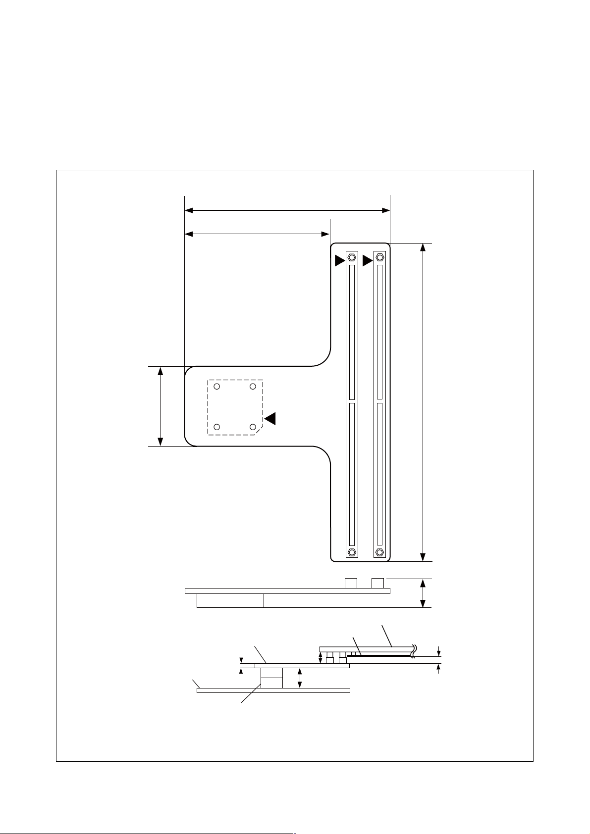
3. Notes on Designing
■ Notes on designing the printed circuit board for the user system
If the header board is connected to a user system, the heights of parts mounted around the
header board are restricted.
When designing the printed circuit board of the user system, consider the heights of components
within the range of the header board, as shown in Figure 1, so that the components mounted on the
user system do not interfere with the header board.
88.0mm
52.0mm
42.0mm
User
system
Header
1.6mm
Approx.
17.0mm*
Insulating plate
Approx.
13.0mm*
Adapter
150.0mm
23.0mm
10.0mm
NQPACK064SB
* : The height differs slightly depending on how the sockets are engaged.
Figure 1 Header board dimensions
2
Page 6

■ MCU footprint design notes
Figure 2 shows the recommended dimensions of the NQPACK footprint mounted on the printed circuit board of the user system.
The printed circuit board of the user system must be designed with due consideration given to this
footprint as well as to the mass production MCU.
For more information, contact the Tokyo Eletech Corporation.
0.65mm
1.8mm
0.65mm × 15 = 9.75mm
0.4mm
φ2.2mm*
12.0mm
2
3-φ1.0mm*
5.0mm
1
0.65mm × 15 = 9.75mm
No.1 pin
1.8mm
5.0mm
12.0mm
1.8mm
1.8mm
*1 : Position of the guide pin hole (φ1.0) when mounting the NQPACK.
These holes do not need to be fabricated if the guide pins are not used.
*2 : Position of the hole (φ2.2) for the screw for affixing the IC socket when the NQPACK064SB-SL
(Tokyo Eletech Corporation, sold separately) is mounted instead of the NQPACK064SB-SL.
This hole does not need to be fabricated if the NQPACK064SB-SL is not used.
Figure 2 Recommended dimensions of the footprint for mounting the NQPACK
3
Page 7

4. Procedure for Connecting to the User System
Before using the MB2198-304, mount the supplied NQPACK on the user system.
Connect the header board directly to the adapter. Refer to the operation manual of the adapter for
details on how to connect the adapter.
■ Connecting
1. To connect the header board to the user system, align pin 1 indicated by the index mark (▲) on
the NQPACK mounted on the user system with the index mark (▲) on the header board and then
insert it (See Figure 3) .
The YQPACK pins are thin and easy to bend. Check that the YQPACK pins are not bent before
inserting it into the NQPACK.
2. Insert each of the screws for securing the header board through a washer and into each of the four
holes in the header board. Partially tighten one of the screws with the special screwdriver supplied
with the NQPACK and then partially tighten the screw in the diagonally opposite corner. Partially
tighten the two remaining screws. Finally repeat the process making the screws equally tight.
(See Figure 4) .
Take care not to overtighten the screws as this may cause a faulty connection.
Adapter I/F connector 2
Adapter I/F connector 1
NQPACK
Index mark (▲)
YQPACK
(It mounts at the back)
Header board
Index mark (▲)
Figure 3 Index position
4
Page 8

■ Disconnection
Screws for securing
the header board
Header board
Washer
YQPACK
User system
NQPACK
Figure 4 Header board connection
To disconnect the header board from the user system, remove all four screws, and then pull the
header board straight out of the NQPACK.
5
Page 9

5. Mounting Mass Production MCUs
Use the supplied HQPACK to mount a mass production MCU on the user system.
■ Mounting
1. To mount a mass production MCU on the user system, align the index mark (▲) on the NQPACK
mounted on the user system with the index mark (●) on the mass production MCU.
2. Confirm that the mass production MCU is correctly mounted on the NQPACK, and then align the
index mark (the only corner with an angle cut-out) of the HQPACK with the index mark of the
NQPACK, and insert it (See “Figure 5”).
The HQPACK pins are thin and easy to bend. Check that the HQPACK pins are not bent before
inserting it into the NQPACK.
3. Insert each of the screws for securing the HQPACK into each of the four screw holes on the HQ-
PACK and tighten the diagonally opposite screws in turn.
To tighten the screws, use the special screwdriver supplied with the NQPACK to finally tighten
the four screws in sequence. Tightening the screws too tight might result in a defective contact.
Screws for securing
the HQPACK
■ Disconnection
HQPACK
Mass production MCU
User system
NQPACK
Figure 5 Mounting a mass production MCU
To remove the HQPACK, remove all of the four screws, and pull the HQPACK vertically out from
the NQPACK.
6
Page 10

6. Connector Pin Assignment
The signals from the evaluation MCU mounted on the adapter board are connected to the YQPACK
(the same assignments as mass production MCU) via adapter I/F connectors 1 and 2 on the header
board.
For details on the mass production MCU pins, refer to the data sheet or hardware manual of each
MCU.
■ Pin assignment
Tables 1 to 4 show the correspondence between the pin numbers for adapter I/F connectors 1 and 2,
the evaluation MCU on the adapter board, and the mass production MCU.
The following explanations apply to these tables. Row A corresponds to the side of the connector
that displays the polarity. Row B corresponds to the opposite side.
*1 : No connection. These are not connected on either evaluation MCUs or mass production MCUs.
*2 : Pin 18 on mass production MCUs is connected to pins AA38, Y37, Y36, and Y35 on evaluation
MCUs.
- : Unconnected (open) pin
: VCC
The evaluation MCU power supply pins (VCC) are as follows:
VCC=Y38, W38, W36, W35, G5, L5, AR7, AM35, H35, D8, R5, W5, AC5, AG5, AP11,
AP19, AP23, AP31, AH34, AD34, T34, H34, E32, E28, E20, E12, G4, AL4, AR31,
D32, AL5, AP7, AP15, AP27, AR7, AM34, Y34, M34, E24, E16, E8, AP33, AP29,
AP25, AP21,AP13, AA5, D15, D25, R35, AE35, AR24, P4, AP17, AP9, AN5, AJ5,
AE5, U5, N5, J5,AR14, AD4, AK34, AF34, AB34, V34, P34, K34, F34, E30, E26, E22,
E18, E14, E10, E6
The mass production MCU power supply (VCC) pin numbers are 16 and 48.
: VSS
The evaluation MCU ground pins (VSS) are as follows:
VSS = E11, E15, E19, E23, E27, E31, G34, L34, R34, W34, AA34, AE34, M5, C3, B37, T5,
Y5, AD5, AJ34, AH5, AT36, AT3, AU37, AU2, AK5, AP8, AP12, AP16, AP20, AP24,
AP28, AP30, AL34, A1, B1, AU1, AV1, AV2, AV37, AV38, AU38, B38, A38, A37,
A2, C36, D4, AR4, AR35, D35, E5, K5, P5, V5, AB5, AF5, AM5, AP5, AP6, AP10,
AP14, AP18, AP22, AP26, AP32, AP34, AN34, AG34, AC34, U34, N34, J34, E34,
E33, E29, E25, E21, E17, E13, E7
The mass production MCU ground (VSS) pin numbers are 17, 33, and 49.
7
Page 11

Table 1 Adapter I/F Connector 1 (Row A)
Connector
Pin No.
Mass Production
MCU Pin No.
Evaluation MCU
Pin No.
Connector
Pin No.
Mass Production
MCU Pin No.
Evaluation MCU
A1 VCC A51 GND
A2 VCC A52 GND
A3 - J36 A53 - C30
A4 - H37 A54 - A32
A5 - K36 A55 - C31
A6 - J35 A56 - D30
A7 - J83 A57 - B31
A8 - K35 A58 - D31
A9 - J37 A59 - B32
A10 - K38 A60 - A33
A11 GND A61 GND
A12 GND A62 GND
A13 - E38 A63 61 D28
A14 - F37 A64 62 A30
A15 - F38 A65 59 D29
A16 - G35 A66 60 C28
A17 - G38 A67 - B29
A18 - H36 A68 - C29
A19 - G37 A69 - B30
A20 - H38 A70 - A31
A21 GND A71 GND
A22 GND A72 GND
A23 - C38 A73 32 C26
A24 - D37 A74 31 A28
A25 - D38 A75 42 C27
A26 - E35 A76 41 D26
A27 - F36 A77 - B27
A28 - F35 A78 - D27
A29 - E37 A79 - A29
A30 - G36 A80 - B28
A31 GND A81 - AC38
A32 GND A82 - AB36
A33 - C34 A83 - AC36
A34 - A36 A84 - AC35
A35 - C35
A85 GND
A36 - B35 A86 - AF38
A37 - D36 A87 - AD36
A38 - B36 A88 - AE36
A39 - E36 A89 - AG38
A40 - C37 A90 - A41 GND A91 - AD3
A42 GND A92 - AC3
A43 - C32 A93 - A44 - A34
A45 - C33
A94 VCC
A95 GND
A46 - B33 A96 40 AD1
A47 - D33
A97 GND
A48 - B34 A98 - AD2
A49 - D34
A50 - A35 A100
A99 GND
NC*
1
Pin No.
8
Page 12

Table 2 Adapter I/F Connector 1 (Row B)
Connector
Pin No.
B1 - B2 - -
Mass Production
MCU Pin No.
Evaluation MCU
Pin No.
Connector
Pin No.
Mass Production
MCU Pin No.
B51 GND
B52 GND
Evaluation MCU
Pin No.
B3 - B23 B53 57 B13
B4 - A26 B54 58 A14
B5 - B24 B55 - C15
B6 - C24 B56 56 B14
B7 - B25 B57 54 B15
B8 - C25 B58 55 C16
B9 - B26 B59 - B16
B10 - A27 B60 53 A15
B11 GND B61 GND
B12 GND B62 GND
B1351C22B6322B11
B1452A24B6421A12
B1547C23B6524C13
B1650B21B6623B12
B17 45 D23 B67 13 C9
B1846B22B6812 B8
B19 43 A25 B69 - A13
B20 44 D24 B70 - D14
B21 GND B71 GND
B22 GND B72 GND
B23 - D20 B73 - B9
B24 - B20 B74 - A10
B25 - D21 B75 - C11
B26 - A21 B76 - B10
B27 - C21 B77 - D11
B28 - A22 B78 - C12
B29 - D22 B79 - D12
B30 - A23 B80 - A11
B31 GND B81 - AD38
B32 GND B82 - AA37
B33 - D18 B83 - AB37
B34 - A18 B84 - AD35
B35 - D19 B85 - AE38
B36 - B19 B86 - AC37
B37 - C19 B87 - AD37
B38 - A19 B88 - AE37
B39 - C20
B89 GND
B40 - A20 B90 - B41 GND B91 - L4
B42 GND B92 - L3
B43 26 D16 B93 - B44 25 A16
B94 VCC
B45 - C17 B95 18 *2
B46 27 D17 B96 - B47 29 C18 B97 - B48 28 B17 B98 - B49 - A17 B99 - -
B50 30 B18 B100
NC
*1
9
Page 13

Table 3 Adapter I/F Connector 2 (Row A)
Connector
Pin No.
A1 VCC A51 GND
A2 VCC A52 GND
A3 11 B7 A53 3 J1
A4 10 A8 A54 2 L2
A5 - C14 A55 5 C2
A6 - D13 A56 4 D3
A7 15 C10 A57 7 B3
A8 14 D9 A58 6 C4
A9 20 A9 A59 9 B4
A1019D10A60 8 C5
A11 GND A61 GND
A12 GND A62 GND
A13 - E2 A63 - L1
A14 - F2 A64 - N2
A15 - D1 A65 - N4
A16 - F4 A66 - N3
A17 - C1 A67 - M4
A18 - E4 A68 - M3
A19 - D2 A69 - K1
A20 - E3 A70 - M2
A21 GND A71 GND
A22 GND A72 GND
A23 - H4 A73 - N1
A24 - J4 A74 - P1
A25 - F1 A75 - R3
A26 - H2 A76 - T2
A27 - E1 A77 - P3
A28 - G2 A78 - R2
A29 - F3 A79 - M1
A30 - G3 A80 - P2
A31 GND A81 - AF37
A32 GND A82 - AF36
A33 - K3 A83 - AG36
A34 - K4 A84 - AG37
A35 - H1
A36 - K2 A86 - AK38
A37 - G1 A87 - AH36
A38 - J2 A88 - AJ36
A39 - H3 A89 - AL38
A40 - J3 A90 39 AE1
A41 GND A91 37 AE2
A42 GND A92 - A43 - D5
A44 - A3
A45 - D6
A46 - A4
A47 - C7
A48 - C6 A98 - AB38
A49 - A5
A50 - B5
Mass Production
MCU Pin No.
Evaluation MCU
Pin No.
Connector
Pin No.
A85 GND
A93 63 A6
A94 64 C8
A95 64 E9
A96 VCC
A97 GND
A99 GND
A100 GND
Mass Production
MCU Pin No.
Evaluation MCU
Pin No.
10
Page 14

Table 4 Adapter I/F Connector 2 (Row B)
Connector
Pin No.
B1 - - B51 - L37
B2 - - B52 - M38
B3 - - B53 - M37
B4 - -
B5 - R1 B55 - N35
B6 - U4 B56 - N36
B7 - V2 B57 - P35
B8 - U3 B58 - P36
B9 - U2 B59 - P38
B10 - T3 B60 - N38
B11 - R4
B12 - T4 B62 - N37
B13 GND B63 - R36
B14 GND B64 - P37
B15 - W2 B65 - R37
B16 - W3 B66 - T36
B17 - V1 B67 - T37
B18 - W4 B68 - R38
B19 - U1 B69 - T35
B20 - V4 B70 - T38
B21 - T1 B71 - U35
B22 - V3
B23 GND B73 - U37
B24 GND B74 - U36
B25 - AA1 B75 - V37
B26 - AB1 B76 - V36
B27 - Y2 B77 - V38
B28 - AA4 B78 - U38
B29 - Y1
B30 - Y4 B80 - V35
B31 - W1 B81 - AH38
B32 - Y3 B82 - AF35
B33 GND B83 - AG35
B34 GND B84 - AH37
B35 - AC1 B85 - AJ38
B36 - AC2 B86 - AH35
B37 - AB4 B87 - AJ35
B38 - AC4 B88 - AJ37
B39 - AB2
B40 - AB3 B90 38 AF2
B41 - AA2 B91 - B42 - AA3 B92 - B43 GND B93 1 D7
B44 GND B94 1 B6
B45 - L36
B46 - K37
B47 - L35
B48 - M36 B98 34 AA36
B49 - M35
B50 - L38 B100 35 AB35
Mass Production
MCU Pin No.
Evaluation MCU
Pin No.
Connector
Pin No.
B54 GND
B61 GND
B72 GND
B79 GND
B89 GND
B95 63 A7
B96 VCC
B97 GND
B99 GND
Mass Production
MCU Pin No.
Evaluation MCU
Pin No.
11
Page 15

SS01-71060-1E
FUJITSU SEMICONDUCTOR • SUPPORT SYSTEM
DSU-FR EMULATOR
LQFP-64P HEADER TYPE 2
MB2198-304
OPERATION MANUAL
February 2007 the first edition
Published FUJITSU LIMITED Electronic Devices
Edited Business Promotion Dept.
Page 16

 Loading...