

Page 1
USER’S MANUAL
LCD PROJECTOR
LPF-D711W
AV SELECTOR
LPF-QSD1W
EnglishDeutschEspañolFrançaisItalianoPortuguês
Contents
Page Page
Before Use
• SAFETY PRECAUTIONS ............................................E-2
• INFORMATION ............................................................E-4
• ADDITIONAL PRECAUTIONS .....................................E-6
• INSTALLATION............................................................E-9
Usage
• PART NAMES AND FUNCTIONS .............................E-12
• USING THE REMOTE CONTROL.............................E-18
• CONNECTING THE DISPLAY TO EXTERNAL
EQUIPMENT..............................................................E-20
• BASIC OPERATIONS ................................................E-29
• SELECTING INPUT MODE .......................................E-34
• OTHER BASIC OPERATIONS ..................................E-35
• WATCHING PICTURES ON THE WIDE SCREEN.... E-36
Adjustments
• ADJUSTMENT MENU................................................E-38
• BASIC PROCEDURE OF ADJUSTMENT MENU
OPERATIONS............................................................E-39
• ADJUSTING THE PICTURE ......................................E-40
Before using the display, read this manual carefully so that you know how to use the display correctly.
Refer to this manual whenever questions or problems about operation arise. Be sure to read and observe the safety
precautions.
Keep this manual where the user can see it easily.
* Installation and removal require special expertise. Consult your product dealer for details.
• ADJUSTING SCREEN POSITION AND SIZE ...........E-46
• OTHER ADJUSTMENTS ...........................................E-47
• INITIALIZATION OF USER ADJUSTMENT VALUE ..E-53
• CLEANING AND MAINTENANCE ............................. E-54
Others
• OPTIONS ...................................................................E-59
• MAIN SUPPORTED SIGNALS...................................E-60
• SPECIFICATION ........................................................E-61
Póññêèé
Ё᭛
ġུġࢊ
Page 2
SAFETY PRECAUTIONS
Dear Customer:
We have prepared this USER'S MANUAL to assist you in the operation of your new LCD Projector. We thank you for your purchase and
hope you will be satisfied with the quality and performance of this projector. Please read the instructions carefully, and keep them
available for future reference.
IMPORTANT INFORMATION
IMPORTANT
RISK OF ELECTRIC SHOCK.
DO NOT REMOVE SCREWS EXCEPT
IF SPECIFIED USERSERVICE
SCREWS MARKED
The lightning flash with arrowhead symbol, within
an equilateral triangle, is intended to alert the user
to the presence of uninsulated “dangerous voltage”
within the product’s enclosure that may be of
sufficient magnitude to constitute a risk of electric
shock to persons.
CAUTION:
TO PREVENT THE RISK OF ELECTRIC
SHOCK, DO NOT REMOVE COVER (OR
BACK). NO USER-SERVICEABLE PARTS
INSIDE. REFER SERVICING TO QUALIFIED
SERVICE PERSONNEL.
The exclamation point within an equilateral triangle
is intended to alert the user to the presence of
important operating and maintenance (servicing)
instructions in the literature accompanying the
appliance.
WARNING: THIS UNIT HAS AN EXTREMELY BRIGHT LIGHT SOURCE. DO NOT STARE INTO THE BEAM OF LIGHT.
BE ESPECIALLY CAREFUL THAT CHILDREN DO NOT STARE DIRECTLY INTO THE LIGHT.
WARNING: TO REDUCE THE RISK OF FIRE AND ELECTRIC SHOCK, DO NOT EXPOSE THIS
PRODUCT TO RAIN OR MOISTURE.
FCC NOTICE
• A Class A digital device
This equipment has been tested and found to comply with the limits for a Class A digital device, pursuant to Part 15 of the FCC Rules. These
limits are designed to provide reasonable protection against harmful interference when the equipment is operated in a commercial
environment. This equipment generates, uses, and can radiate radio frequency energy and, if not installed and used in accordance with the
instruction manual, may cause harmful interference to radio communications. Operation of this equipment in a residential area is likely to
cause harmful interference in which case the user will be required to correct the interference at his own expense.
• A Class B digital device
This equipment has been tested and found to comply with the limits for a Class B digital device, pursuant to Part 15 of the FCC Rules. These
limits are designed to provide reasonable protection against harmful interference in a residential installation. This equipment generates, uses
and can radiate radio frequency energy and, if not installed and used in accordance with the instructions, may cause harmful interference to
radio communications. However, there is no guarantee that interference will not occur in a particular installation. If this equipment does cause
harmful interference to radio or television reception, which can be determined by turning the equipment off and on, the user is encouraged to
try to correct the interference by one or more of the following measures:
– Reorient or relocate the receiving antenna.
– Increase the separation between the equipment and receiver.
– Connect the equipment into an outlet on a circuit different from that to which the receiver is connected.
– Consult the dealer or an experienced radio/TV technician for help.
IMPORTANT SAFETY INSTRUCTIONS
Electrical energy can perform many useful functions. This unit has been engineered and manufactured to assure your personal safety. But
IMPROPER USE CAN RESULT IN POTENTIAL ELECTRICAL SHOCK OR FIRE HAZARD. In order not to defeat the safeguards
incorporated into this product, observe the following basic rules for its installation, use and service. Please read these “Important Safeguards”
carefully before use.
1) Read these instructions.
2) Keep these instructions.
3) Heed all warnings.
4) Follow all instructions.
5) Do not use this apparatus near water.
6) Clean only with dry cloth.
7) Do not block any ventilation openings. Install in accordance with the manufacturer’s instructions.
8) Do not install near any heat sources such as radiators, heat registers, stoves, or other apparatus (including amplifier’s) that produce heat.
9) Do not defeat the safety purpose of the polarized or grounding-type plug. A polarized plug has two blades with one wider than the other. A
grounding type plug has two blades and a third grounding prong. The wide blade or the third prong are provided for your safety. If the
provided plug does not fit into your outlet, consult an electrician for replacement of the obsolete outlet.
10) Protect the power cord from being walked on or pinched particularly at plugs, convenience receptacles, and the point where they exit from
the apparatus.
11) Only use attachments/accessories specified by the manufacturer.
12) Use only with the cart, stand, tripod, bracket, or table specified by the manufacturer, or sold with the apparatus.
When a cart is used, use caution when moving the cart/apparatus combination to avoid injury from tip-over.
13) Unplug this apparatus during lightning storms or when unused for long periods of time.
E-2
Page 3
14) Refer all servicing to qualified service personnel. Servicing is required when the apparatus has been damaged in any way, such as powersupply cord or plug is damaged, liquid has been spilled or objects have fallen into the apparatus, the apparatus has been expos ed to rain or
moisture, dose not operate normally, or has been dropped.
– Unplug this product from the wall outlet before cleaning. Do not use liquid cleaners or aerosol cleaners. Use a damp cloth for cleaning.
– Do not use attachments not recommended by the product manufacturer as they may cause hazards.
– Do not use immediately after moving from a low temperature to high temperature, as this causes condensation, which may result in fire,
electric shock, or other hazards.
– The apparatus shall not be exposed to dripping or splashing.
– No objects filled with liquids, such as vases, shall be placed on the apparatus.
– Do not place this product on an unstable cart, stand, or table. The product may fall, causing serious injury to a child or adult, and serious
damage to the product. The product should be mounted according to the manufacturer ’s instructions, and should use a mount
recommended by the manufacturer.
– When the product is used on a cart, care should be taken to avoid quick stops, excessive force, and uneven surfaces which may cause the
product and cart to overturn, damaging equipment or causing possible injury to the operator.
– Slots and openings in the cabinet are provided for ventilation. These ensure reliable operation of the product and protect it from
overheating. These openings must not be blocked or covered. (The openings should never be blocked by placing the product on bed, sofa,
rug, or other similar surface. It should not be placed in a built-in installation such as a bookcase or rack unless proper ventilation is
provided and the manufacturer’s instructions have been adhered to.)
For proper ventilation, separate the product from other equipment, which may prevent ventilation, and keep distance more than 10 cm.
– This product should be operated only from the type of power source indicated on the label. If you are not sure of the type of power supply
of your home, consult your product dealer or local power company.
– This product is equipped with a three-wire plug. This plug will fit only into a grounded power outlet. If you are unable to insert the plug
into the outlet, contact your electrician to install the proper outlet. Do not defeat the safety purpose of the grounded plug.
– Power-supply cords should be routed so that they are not likely to be walked on or pinched by items placed upon or against them. Pay
particular attention to cords at doors, plugs, receptacles, and the point where they exit from the product.
– For added protection for this product during a lightning storm, or when it is left unattended and unused for long periods of time, unplug it
from the wall outlet and disconnect the cable system. This will prevent damage to the product due to lightning and power line surges.
– Do not overload wall outlets, extension cords, or convenience receptacles on other equipment as this can result in a risk of fire or electric shock.
– Never push objects of any kind into this product through openings as they may touch dangerous voltage points or short out parts that could
result in a fire or electric shock. Never spill liquid of any kind on the product.
– Do not attempt to service this product yourself as opening or removing covers may expose you to dangerous voltages and other hazards.
Refer all service to qualified service personnel.
– Unplug this product from the wall outlet and refer service to qualified service personnel if the product does not operate normally by
following the operating instructions. Adjust only those controls that are covered by the Operation Manual, as an improper adjustment of
other controls may result in damage and will often require extensive work by a qualified technician to restore the product to its normal
operation.
– When replacement parts are required, be sure the service technician has used replacement parts specified by the manufacturer or with same
characteristics as the original part. Unauthorized substitutions may result in fire, electric shock, or other hazards.
– Upon completion of any service or repairs to this product, ask the service technician to perform safety checks to determine that the product
is in proper operating condition.
– The product should be placed more than one foot away from heat sources such as radiators, heat registers, stoves, and other products
(including amplifiers) that produce heat.
– When connecting other products such as VCR’s, and personal computers, you should turn off the power of this product for protection
against electric shock.
– Do not place combustibles behind the cooling fan. For example, cloth, paper, matches, aerosol cans or gas lighters that present special
hazards when overheated.
– Use only the accessory cord designed for this product to prevent shock.
The power supply voltage rating of this product is AC110–240 V and the power cord attached conforms to the following power supply
voltage. Use only the power cord designated by our dealer to ensure Safety and EMC.
When it is used with other power supply voltage, the power cable must be changed.
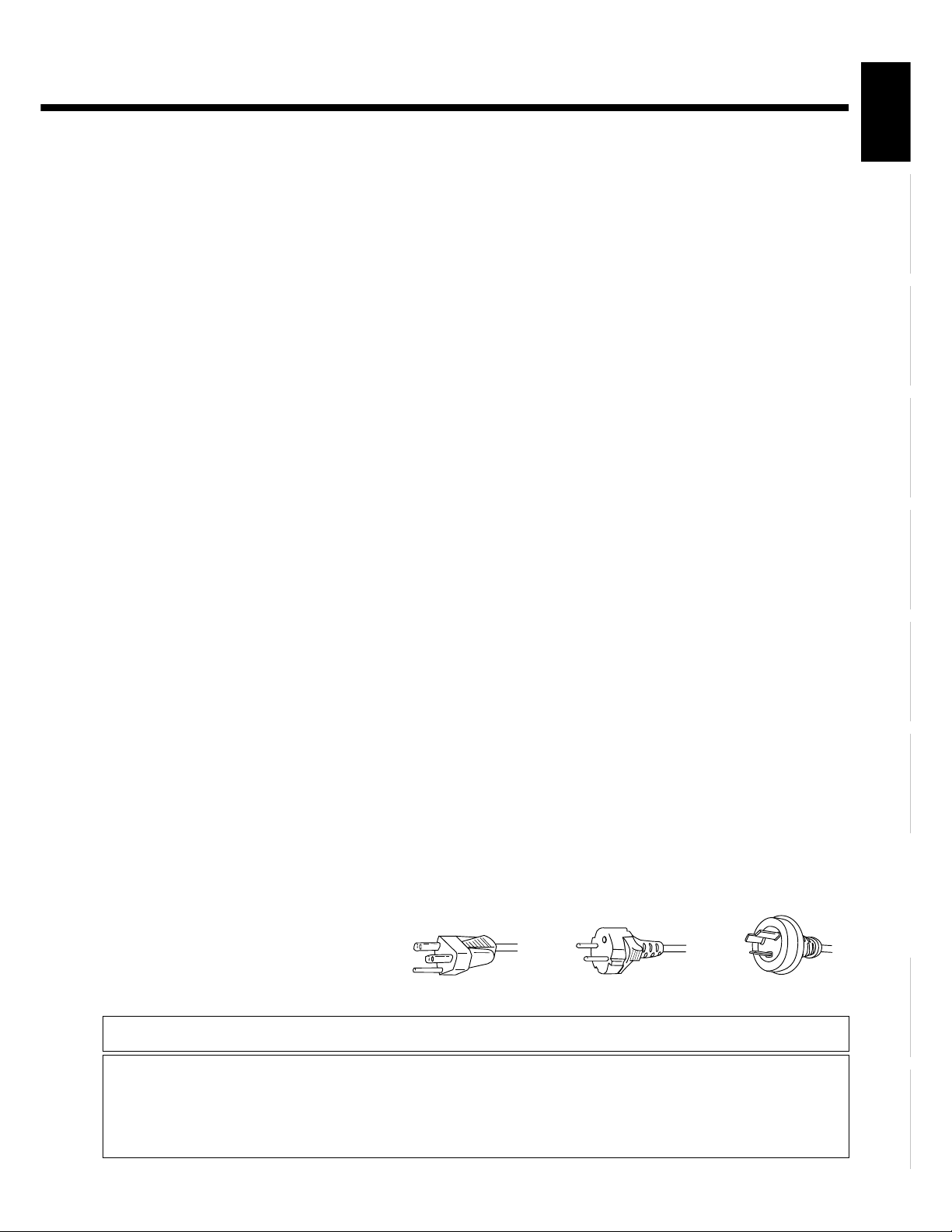
Use the standard power plug and cord set of the specified country.
Consult your product dealer.
Power cord
EnglishDeutschEspañolFrançaisItalianoPortuguês
Póññêèé
Power supply voltage: AC 100–125 V AC 200–240 V AC 240 V (SAA TYPE)
About the lithium battery
Warning
• Keep the lithium battery out of reach of children. Should the battery be swallowed, immediately consult a doctor.
CAUTION
• Do not recharge, disassemble, short-circuit, modify, heat or dispose of battery in fire.
• Use batteries within the use-by date.
• Do not handle the battery with metallic tools.
• Do not store the lithium battery with metallic materials.
• When disposing of used batteries, please comply with governmental regulations or environmental public institution's rules that apply in your country/
area.
• Always check carefully that you are loading battery with its (+) and (-) poles facing in the proper directions.
Ё᭛
ġུġࢊ
E-3
Page 4

INFORMATION
• Receptacle
Make sure that the power cable’s grounding wire is grounded.
The display comes with a 3-prong power plug; one prong is connected to the grounding wire. If you have only a 2-hole receptacle, you
will need to have it replaced. Contact your dealer for more information.
• Have the display inspected and cleaned by your dealer at regular intervals.
• The liquid crystal panels are manufactured with very precision techniques resulted in 99.99% or more effective pixels. Please understand
that some panels lack 0.01% or less pixels and keep the light on at all times.
• This projector is equipped with a heat-emitting fan for prevention of increasing temperature inside during operation. Note that heated air
blows out of the fan.
• Contact your dealer if you find that the display does not seem to function properly when used with other audio-visual equipment.
You may need to move your display if it produces degraded pictures or noise due to electromagnetic radiation, or if the infrared remote
control does not function properly.
• Pictures may not be displayed properly if you connect a non-standard PC to the RGB input terminal. In this case, contact your dealer for
more information.
• The protective circuit, built into the display, automatically turns off the power if the display has a problem. In this case, you will see that
the power indicator lamp flashes red or green.
• The ventilation should not be impeded by covering the ventilation openings with items , such as newspapers , table-cloths, curtains,etc.:
– no naked flames sources , such as lighted candles, should be placed on the apparatus:
– no object filled with liquids, such as vases, shall be placed on the apparatus.
Warning
If the power indicator lamp flashes red or green, this signifies that the display has developed a problem. When this happens, be sure to remove the
power plug from the receptacle to prevent fire or electric shock. Then contact your dealer.
• Install the display in a location close to a main power supply outlet, and where the emergency stop button can be easily reached.
Note
• Cables for connecting the display to external equipment are not supplied. Contact your dealer for more information on these products.
• For clarity of explanation, the devices, accessories, etc. depicted in the photographs and illustrations included herein may differ from the actual ones
in some way or other.
E-4
Page 5
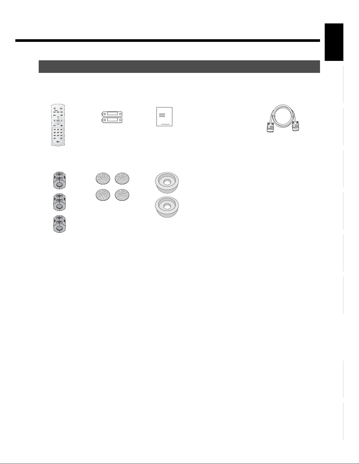
CHECKING ACCESSORIES
EnglishDeutschEspañolFrançaisItalianoPortuguês
One remote control Two AAA batteries One user's manual
Manual
Three ferrite cores
Four air filters Two Antivibration cushions
Two power cables One System cable
(PICTURE)
E-5
Póññêèé
Ё᭛
ġུġࢊ
Page 6

ADDITIONAL PRECAUTIONS
TRANSPORTATION
When transporting the projector unit, take care not to apply undue force to it. Otherwise, lens and other breakable parts may be damaged.
LIGHT SOURCE LAMP
• The light source lamp loses its brightness with use. When the lamp replacement warning
is given, or when the lamp will not light, the picture becomes dim or its color becomes
dull, replace the lamp with a new one. (The light source lamp for replacement can be
purchased from your dealer.)
• When the warning message at right is shown, replace the light source lamp with a new
one.
• For the method of replacing the light source lamp, see page E-56.
GROUNDING
Approaching Recommended
Lamp Life
Warning display for light source lamp
replacement
• Make sure that the grounding work should be performed only by a professional electrician.
• Be sure to make the grounding connection before inserting the power plug into the receptacle. When removing the grounding
connection, pull out the power plug from the receptacle beforehand.
Note
• Turning on and off the power frequently will slightly shorten the life of the light source lamp.
• This device conforms to the harmonic guideline.
E-6
Page 7
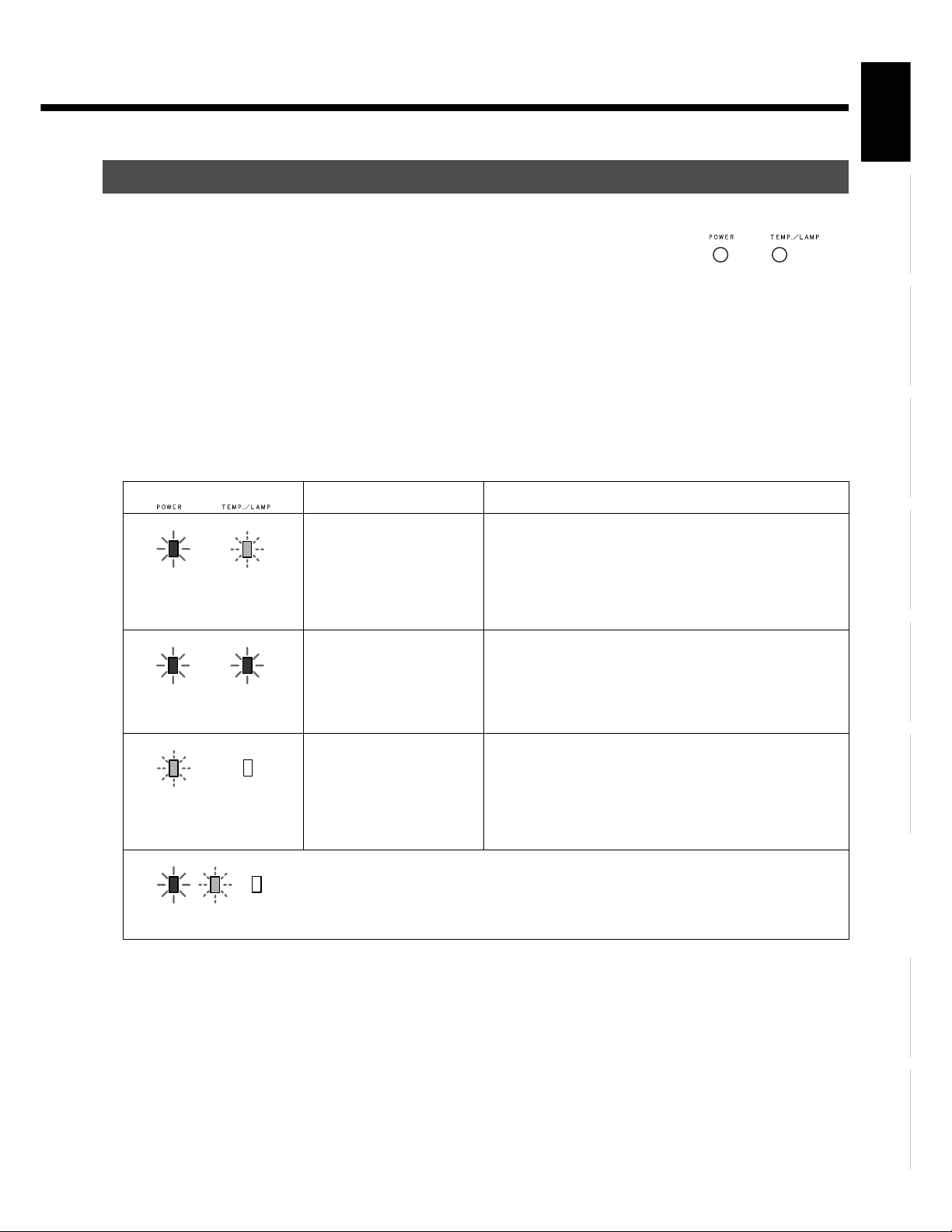
MONITOR INDICATION ON PROJECTOR
• Two monitor indicator lamps provided on the top of the projector signal the abnormal conditions
inside it. (See the illustration at right.)
• After the power plug is inserted into the receptacle, pressing ٤ /I on the right hand side of the
projector's rear and /I on the left hand side of AV selector's front will light up the power indicator
lamp in red to indicate that the projector is on standby.
• While the projector is on standby, pressing "POWER" button will light up the power indicator lamp in
green, and the light source lamp will light up.
• Press POWER while the lamp is on and select OFF on the confirmation screen, the power monitor
indicator lamp blinks in orange letting the lamp cool for about 2 minutes, which follows that the
power monitor lamp lights up in red resulting in a standby state.
• In the case of a trouble, the power, temperature/lamp indicator lamps lights up or blinks, and the
monitors shut off the power automatically. Take the following measures.
Monitor indication Abnormal condition Measures to take
EnglishDeutschEspañolFrançaisItalianoPortuguês
Monitor indicator lamps on the
top of the projector
The power indicator lamp lights
up in red, and the temperature/
lamp indicator lamp blinks in
red.
The power indicator lamp and
temperature/lam indicator lamp
light up in red.
The power indicator lamp
blinks in red and green, and the
temperature/lamp indicator
lamp turns off.
Lighting upBlinking Turned
off
The temperature inside the
projector has risen to an
extraordinary level.
The light source lamp will not
light up.
Abnormal operation of the
projector.
The monitor indication as shown on the left figure indicates to light up in red and green, to blink in
red and green, and to turn off.
If the ventilation openings are blocked with foreign matters,
remove them and re-install the projector so that proper ventilation
is maintained. Check the air filters and lamp protection filter for
accumulation of dust. If they are soiled, clean them or replace
them with new ones (see page E-54). If the abnormal condition
persists despite the above measures, call your dealer for service.
Leave the projector untouched for 2minutes, and then, restart the
projection. By doing so, the cooling fan rotates for approximately
1 minute to cool the inside of the projector. If the abnormal
condition persists despite the above measures, call your dealer for
service.
If the rotation of the cooling fan is blocked by any foreign matters,
remove them. Pull out the power plug from the receptacle, and
leave the projector untouched until its inside cools down. Then,
turn on the power of the projector again. If the abnormal condition
persists despite the above measures, call your dealer for service.
Póññêèé
Note
• While the light source lamp is cooled, do not pull out the power plug from the receptacle, as this may cause damage to the projector as well as shorten
the life of the lamp.
Ё᭛
ġུġࢊ
E-7
Page 8
ADDITIONAL PRECAUTIONS (Continued)
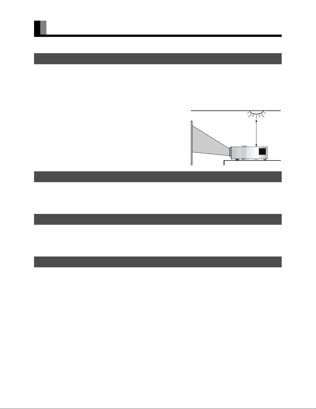
Illuminati
ILLUMINATION NEAR THE PROJECTOR UNIT
Both the projector and AV selector have a signal receiver for the wireless remote control on their front. If a strong light such as fluorescent
light strikes upon the signal receivers, the wireless remote control may not work properly. In that case, keep the projector unit away from
the illumination source such as fluorescent light, or re-install it at a place where light will not directly strike on the signal.
To keep the projector unit away from the illumination source:
As a guideline, keep the projector unit more than 2 m away from the illumination
source such as fluorescent light. Also, check that the signal receivers are not
exposed to direct sunlight.
PICTURE CHARACTERISTICS
on source
More than
2 m
This projector unit uses an LCD panel to project pictures on the screen. Please note, therefore, that the projected picture may differ from
that of the CRT indicator lamp of television and personal computer in color tone and contrast.
PROJECTION SCREEN
When purchasing a projection screen, carefully check the characteristics to select one that best suits your purpose of use. Do not use a
polarizing screen with the projector unit. The screen may be tinged with red.
USE OF A MOBILE PHONE NEAR THE PROJECTION UNIT
Using a mobile phone, transceiver and other device emitting radio waves near the projector unit may disturb the picture. When using those
devices, keep a sufficient distance from the projector unit.
E-8
Page 9
INSTALLATION
(cm)
(cm)
(cm)
(cm)
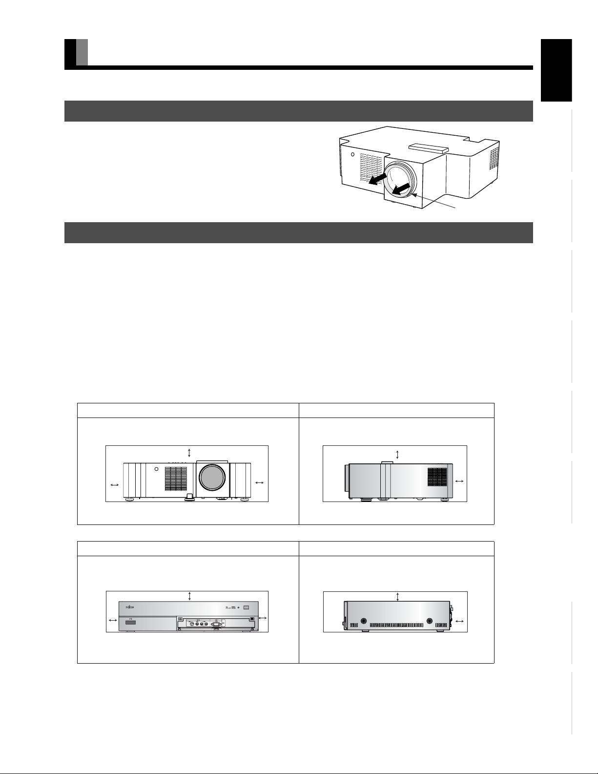
TAKING OUT THE PROJECTOR FROM THE CARTON
Remove the cushioning material for lens protection.
Be sure to remove the cushioning material. If operating focus, zoom, and shift
of the lens with the cushioning material attached, this may cause damage to
the lens.
Cushioning material
INSTALLATION
To prevent increase of temperatures inside the projector, provide a space for draft surrounding the projector. For better heat release, also
provide a space of a minimum distance surrounding the projector, as shown in the figure below.
When installing the projector, be sure to use suspended unit (option) from the ceiling. Call for installation to the local dealer.
See the appropriate instruction manual for more information on the installation hardware you select.
To prevent an accident and ensure safety in the event of an earthquake, fix the display securely into position as described below.
To ensure proper heat radiation, provide at least as much space around the display as shown below.
* Be sure to install the projector at a place that can keep the ambient temperature ranging from 5 to 35 .
* Run the power cords and connection cables along the wall and at the corners of the floor.
* Connect the projector and the AV selector with optical DVI-D cable with care not to bend the cable sharply. Otherwise the cable may
cause damage.
* To prevent the accident and ensure safety against an earthquake, make measures for prevention of falling.
Projector Section
Front Side
EnglishDeutschEspañolFrançaisItalianoPortuguês
20 20
Left
AV Selector section
10
Left
Upper
20
Right
Lower
Upper
Lower
Front Side
Upper
Lower
10
10
Right
Upper
Lower
20
20
Rear
Póññêèé
10
10
Rear
Ё᭛
ġུġࢊ
E-9
Page 10
INSTALLATION (Continued)
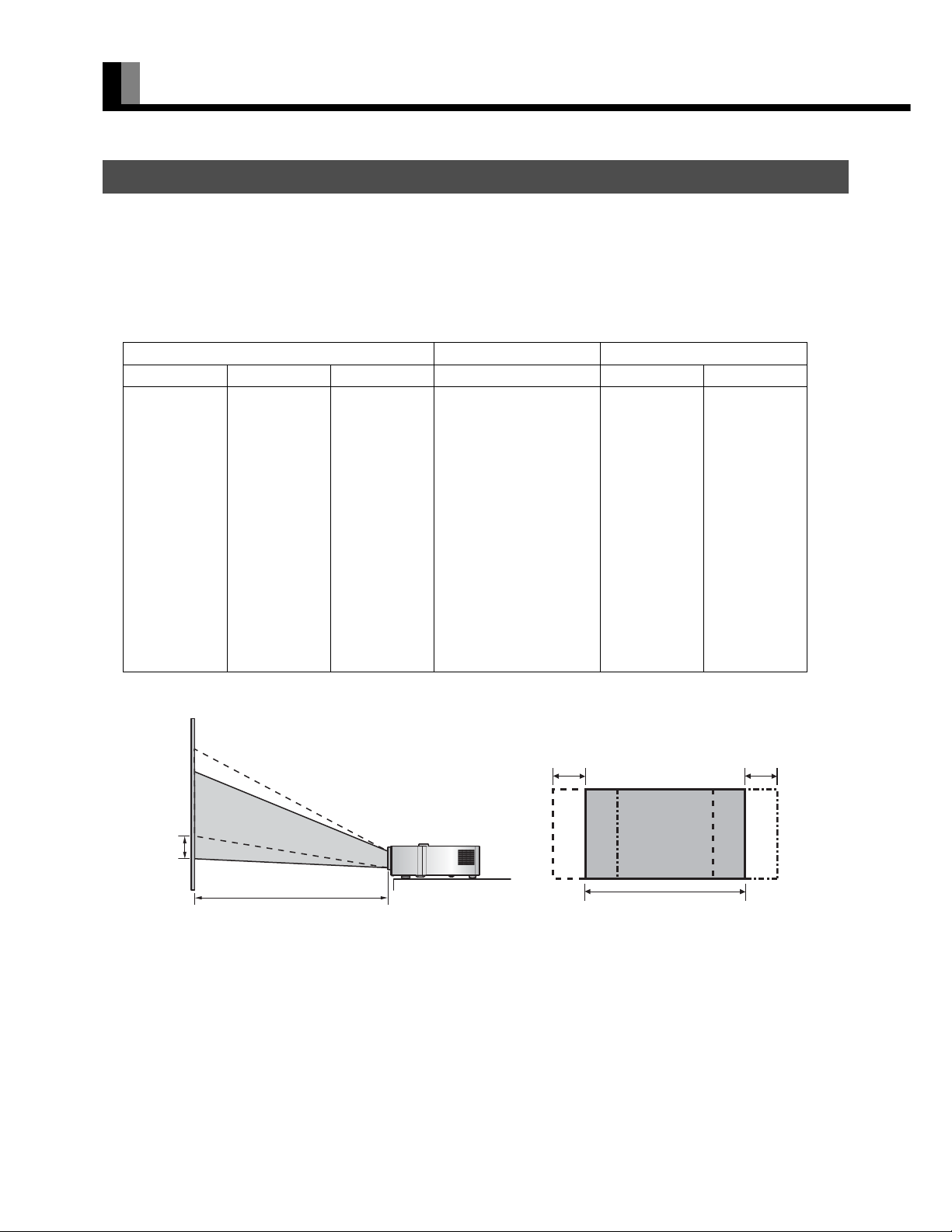
PROJECTION
• Three types of installation are available; front projection, rear projection and ceiling mount projection.
• By adjusting the zoom (see page E-31), the screen size can be selected as shown in the table below.
• By adjusting the lens shift (see page E-31), a suitable projection position can be selected on the screen.
• Projectors have an error of 5% in projection distance and lens shift.
• Optimum projection screen size is 120 to 150 inches.
Projected screen size Projection distance Lens shift
Angle of view (inch)
60 74.7 132.8 2.26-2.85 4.15 7.52
70 87.2 155.0 2.65-3.35 4.85 8.78
80 99.6 177.1 3.04-3.84 5.54 10.03
90 112.1 199.2 3.43-4.34 6.23 11.28
100 124.5 221.4 3.82-4.84 6.92 12.54
110 137.0 243.5 4.21-5.33 7.62 13.79
120 149.4 265.7 4.60-5.83 8.31 15.05
130 161.9 287.8 4.99-6.32 9.00 16.30
140 174.3 309.9 5.38-6.82 9.69 17.55
150 186.8 332.1 5.77-7.32 10.38 18.81
160 199.2 354.2 6.16-7.81 11.08 20.06
170 211.7 376.3 6.55-8.31 11.77 21.32
180 224.1 398.5 6.94-8.80 12.46 22.57
190 236.6 420.6 7.33-9.30 13.15 23.82
200 249.1 442.8 7.72-9.80 13.85 25.08
* "Angle of view" refers to the length of diagonal line of the projected screen.
Height (cm) Width (cm)
Minimum (m)-Maximum (m)
Vertical (cm)
Horizontal (cm)
Lens shift
Ver tical
E-10
Projection distance
Lens shift Horizontal
Projection area on the screen before adjustment
Lens shift Horizontal
Page 11
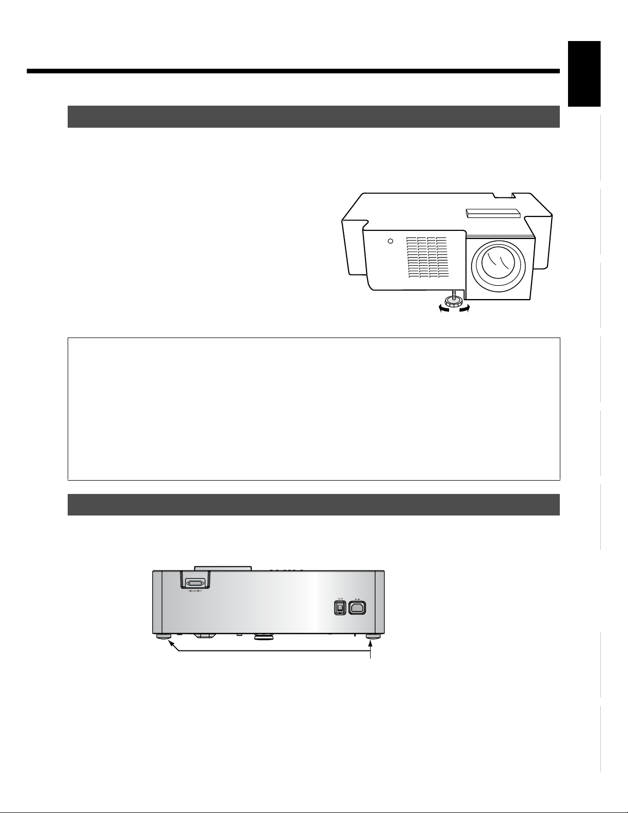
ADJUSTMENT OF PROJECTION POSITION
• Use the three adjusters on the bottom of the projector (one on the front end and two on the rear) to adjust the projection position.
• Unless the projector and projector screen are aligned properly, distorted picture will result.
Lift the front portion of the projector, and
1
2
turn the adjuster on the bottom to adjust
its height.
The length of the adjuster extends as it is turned.
If the picture is tilted rightward or
leftward against the projector screen,
turn either of the two adjusters at the rear
portion of the projector to adjust the
picture position.
The length of the adjuster extends as it is turned.
Warning
• Place the projector at least 20 cm away from the wall. Do not install it at ill-ventilated places. Otherwise, there is the risk of fire.
• Do not install the projector on a carpet or bedding.
Do not block the ventilation openings. Otherwise, a fire will be caused.
• To suspend the projector from the ceiling, request ask your dealer for help. Do not use mounting fittings other than specified by the manufacturer.
Otherwise, risk of the projector falling from the ceiling, personal injury, fire and electric shock will result.
• Use the receptacle near the projector unit that allows easy connection and disconnection of the projector's power plug. When installing the
projector to a place on a permanent basis such as ceiling mount, request a professional electrician to attach a circuit breaker. While the projector
is out of use, be sure to turn off the main power source using the circuit breaker or the like.
• If you find anything unusual about the projector unit, pull out the power plug from the receptacle, or turn off the circuit breaker immediately. If
the projector left as it is, a fire or an electric shock may result.
• When the front of the projector is raised by using the adjuster, do not put your hand on one side of the projector.
It will lurch to cause personal injury or malfunction.
EnglishDeutschEspañolFrançaisItalianoPortuguês
ATTACHMENT OF ANTIVIBRATION CUSHION
• When you make this equipment to project by putting on a desk etc., a small vibration might transfer to the desk etc. Please attach 2
antivibration cushions to 2 rear adjuster for reducing the vibration transfer.
PROJECTOR SECTION-REAR
Note
The display is a highly precise piece of equipment and therefore must be packed properly before transportation. Be sure to use only those packing
materials originally supplied with the display when repacking it.
Reference
See P. E-59 for more information on options.
Attached position of antivibration cushions.
Póññêèé
Ё᭛
ġུġࢊ
E-11
Page 12
PART NAMES AND FUNCTIONS
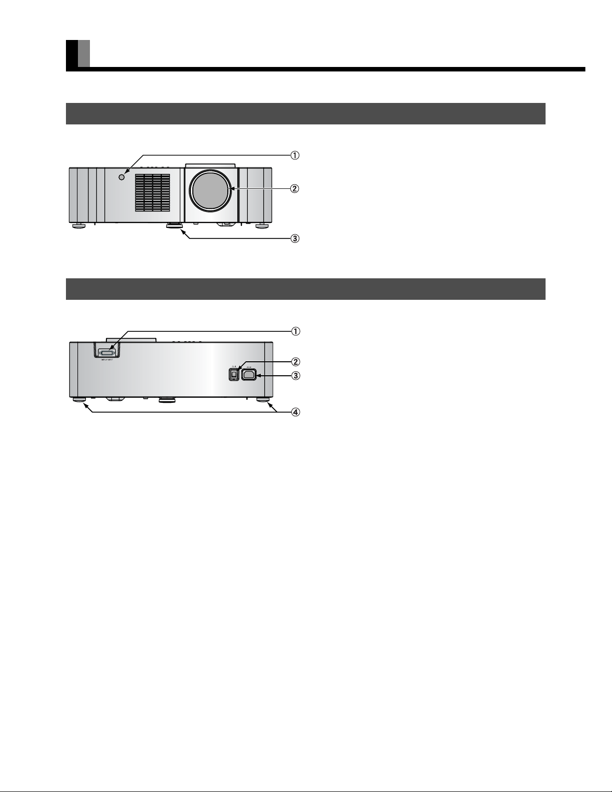
PROJECTOR SECTION - FRONT
Remote control signal receiver
Projector lens
Adjuster (for front end)
PROJECTOR SECTION - REAR
Display input (PICTURE) terminal (DISPLAY INPUT)
٤ /l power switch
Power input terminal
Adjusters (for rear end)
Receives signals from the remote control.
Adjusts the height of projector.
Connect this terminal to the display output (PICTURE) terminal on
the AV selector using the special cable provided.
If this switch is pressed when the power indicator lamp is off, the
indicator lamp will light.
The power can be turned on and the standby mode selected by
using the remote control or the control panel of the display . If this
switch pressed when the power indicator monitor is lit will go out.
Connect the power cable supplied with the projector to this
terminal.
Adjust the height of projector.
E-12
Page 13
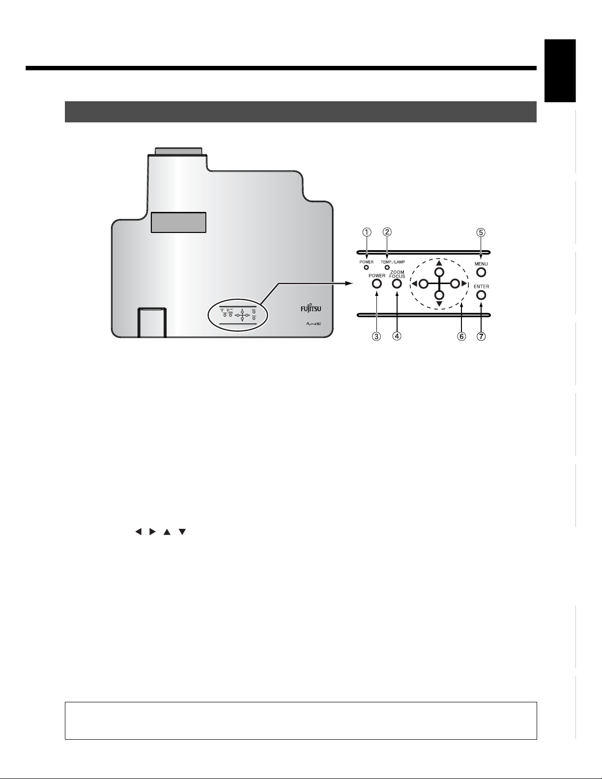
PROJECTOR SECTION - TOP
Power indicator lamp
This lamp shows the state of the power supply.
Lit (red): Standby state
Lit (green): Power ON state
Temperature/lamp indicator lamp
Signals the abnormal condition inside the projector. (See "MONITOR INDICATOIN ON PROJECTOR" on page E-7.)
Power button
Turns the power on and select the standby mode.
Zoom/focus button
Adjusts the size and focus of the picture.
Menu button (MENU)
Shows the menu display for adjusting the picture.
4-way button ( / / / )
Selects the item and adjusts the value in the Menu display.
Enter button
Fixes the entry in the ADJUSTMENT MENU.
EnglishDeutschEspañolFrançaisItalianoPortuguês
Póññêèé
Warning
If the power indicator lamp flashes red or green, this signifies that the display has developed a problem. When this happens, be sure to remove the
power plug from the receptacle and contact your dealer. Leaving the display power ON can result in fire or electric shock.
Ё᭛
ġུġࢊ
E-13
Page 14
PART NAMES AND FUNCTIONS (Continued)
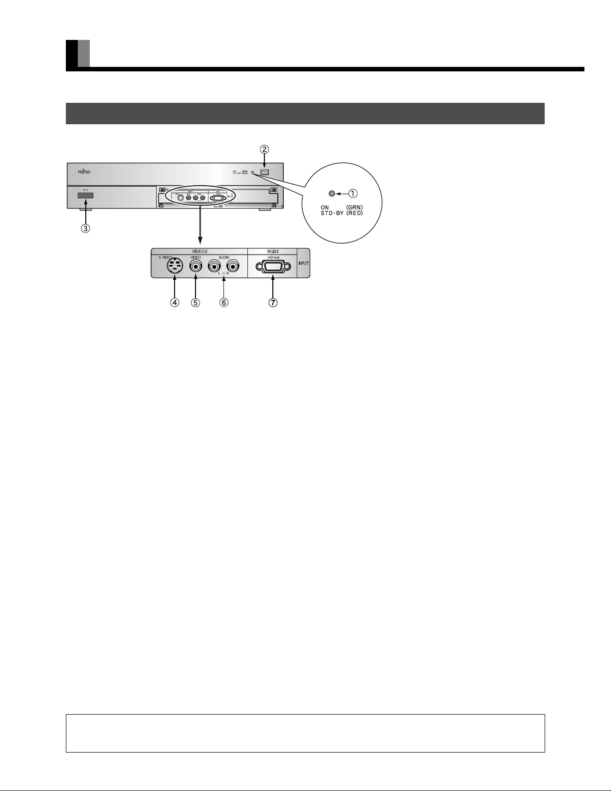
AV SELECTOR SECTION - FRONT
Power indicator lamp
This lamp shows the state of the power supply.
Lit (red): Stand-by
Lit (green): Power ON
Flashing (red or green): Malfunction (Flashes differently depending on the type of malfunction.)
Remote control signal receiver
Receives signals from the remote control.
/l power switch
If this button is pressed with the power indication lamp off, it lights up.
The power can be turned on and the standby mode is selected by using the remote control or the control panel of the display.
If this button is pressed with the power indicator lamp on, it turns off.
*Power is still supplied to parts even if the indicator lamp is off.
Video3, S-video input terminal *
Connect this terminal to the S-video output terminal of your video camera, etc.
Video3, video input terminal *
Connect this terminal to the video output terminal of your video camera, etc.
Audio input terminals (L/R)
These are the audio input terminals for the Video3 and RGB3 terminals.
Input the audio for the video to be seen here.
RGB3 input terminal
Connect this terminal to your PC's mD-sub output terminal.
* On selecting the video input format
(See "SETTING THE INPUT TERMINALS" on P. E-49.)
Warning
If the power indicator lamp flashes red or green, this signifies that the display has developed a problem. When this happens, be sure to remove the
power plug from the receptacle and contact your dealer. Leaving the display power ON can result in fire or electric shock.
E-14
Page 15
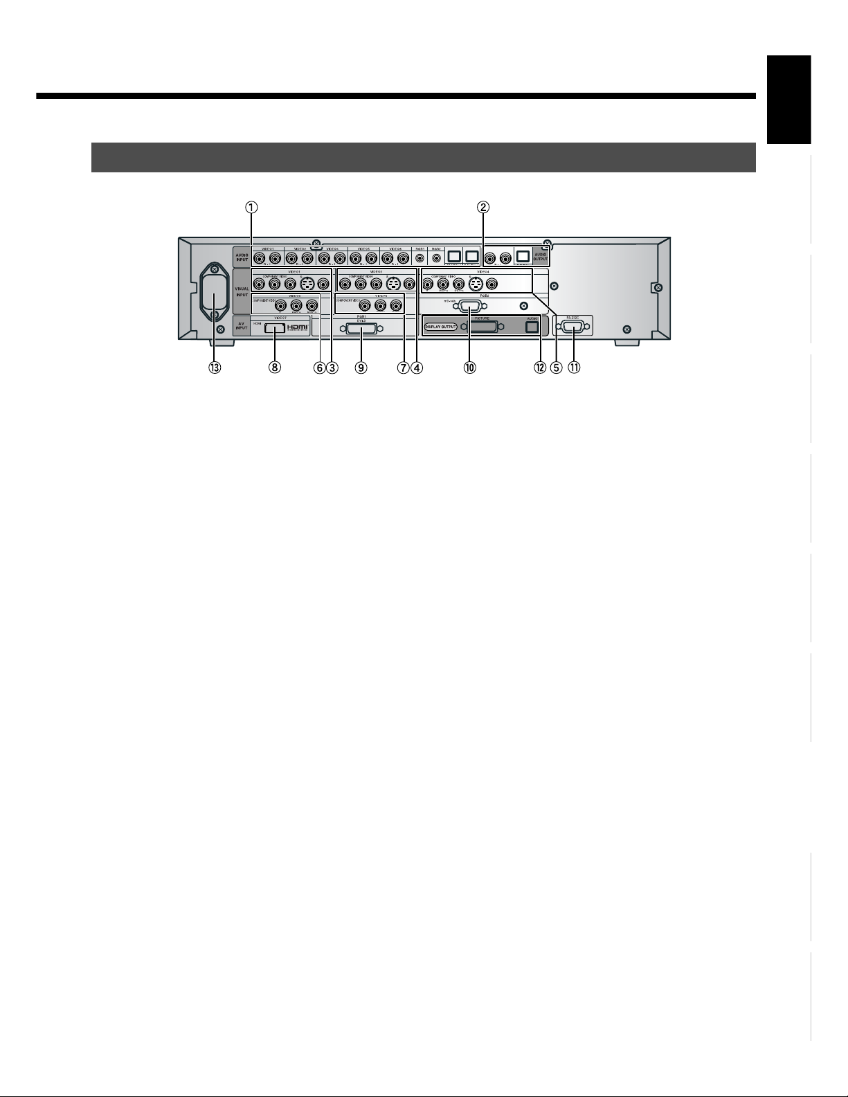
AV SELECTOR SECTION – REAR
Audio input terminals
Input audio through the terminals corresponding to the used video input terminals.
* The digital input terminals can be matched as desired with the remote control. (See P. E-35.)
Audio output terminals
For use when the audio from an audio system (amplifier) is used.
Video1 input terminal
Video2 input terminal
Video4 input terminal
Connect this terminal to the component video output terminal, S-video output terminal, or video output terminal of your VCR or DVD,
etc.
* See "SETTING THE INPUT TERMINALS" on P. E-49.
Video5 input terminal
Video6 input terminal
Connect this terminal to the component video output terminal of your DVD, etc.
Video 7 input terminal
Connect this terminal to HDMI output terminal of your DVD.
RGB1 input terminal
Connect this terminal to the monitor (DVI-D) output terminal of your PC.
RGB2 input terminal
Connect this terminal to the monitor (mD-sub) output terminal of your PC.
RS-232C input terminal
Connect this terminal to the RS-232C output terminal.
Display Output Terminal (PICTURE/AUDIO)
Connect this terminal to the picture input terminal on the projector. (The audio output terminal is not in use.)
" Power input terminal
Connect this terminal to the power cable supplied with the display.
When connecting a cable, attach a ferrite core to the cable. (See P. E-20.)
EnglishDeutschEspañolFrançaisItalianoPortuguês
Póññêèé
Ё᭛
E-15
ġུġࢊ
Page 16
PART NAMES AND FUNCTIONS (Continued)
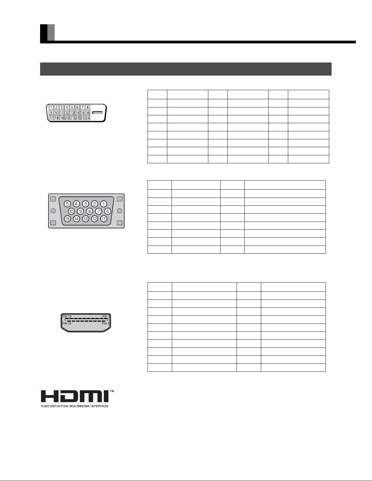
DESCRIPTION OF INPUT TERMINALS
DVI-D terminal (RGB1 INPUT/DVI-D)
(HDCP incompatible)
mD-sub input terminal (RGB2, 3 INPUT/mD-sub)
Pin No. Signal Pin No. Signal Pin No. Signal
1 T.M.D.S. Data2– 9 T.M.D.S. Data1– 17 T.M.D.S. Data0–
2 T.M.D.S. Data2+ 10 T.M.D.S. Data1+ 18 T.M.D.S. Data0+
3
4— 12— 20—
5— 13— 21—
6 DDC Clock 14 +5V Power 22
7 DDC Data 15 Ground (for +5V) 23 T.M.D.S. Clock+
8 — 16 Hot Ploug Detect 24 T.M.D.S. Clock–
1Red 9—
2 Green 10 Ground
3Blue 11—
4— 12—
5 Ground 13 Horizontal synchronization
6 Ground 14 Vertical synchronization
7 Ground 15 —
8 Ground Frame Ground
T.M.D.S. Data2 Shield
Pin No. Input signal Pin No. Input signal
11
T.M.D.S. Data1 Shield
19
T.M.D.S. Data0 Shield
T.M.D.S. Clock Shield
HDMI input terminal (VIDEO7)
Pin No. Input signal Pin No. Input signal
1 T.M.D.S. Data2+ 11 T.M.D.S. Clock Shield
2 T.M.D.S. Data2 Shield 12 T.M.D.S. Clock–
3 T.M.D.S. Data2– 13 CEC
4 T.M.D.S. Data1+ 14 Reserve
5 T.M.D.S. Data1 Shield 15 DDC Clock
6 T.M.D.S. Data1– 16 DDC Data
7 T.M.D.S. Data0+ 17 Ground (for +5V)
8 T.M.D.S. Data0 Shield 18 +5V Power
9 T.M.D.S. Data0– 19 Hot Plug Detect
10 T.M.D.S. Clock+ Frame FG
HDMI (High-Definition Multimedia Interface)
HDMI is a standard for home digital interfaces, which can transmit images as well as multichannel
audio signals and control signals through one cable.
E-16
Page 17
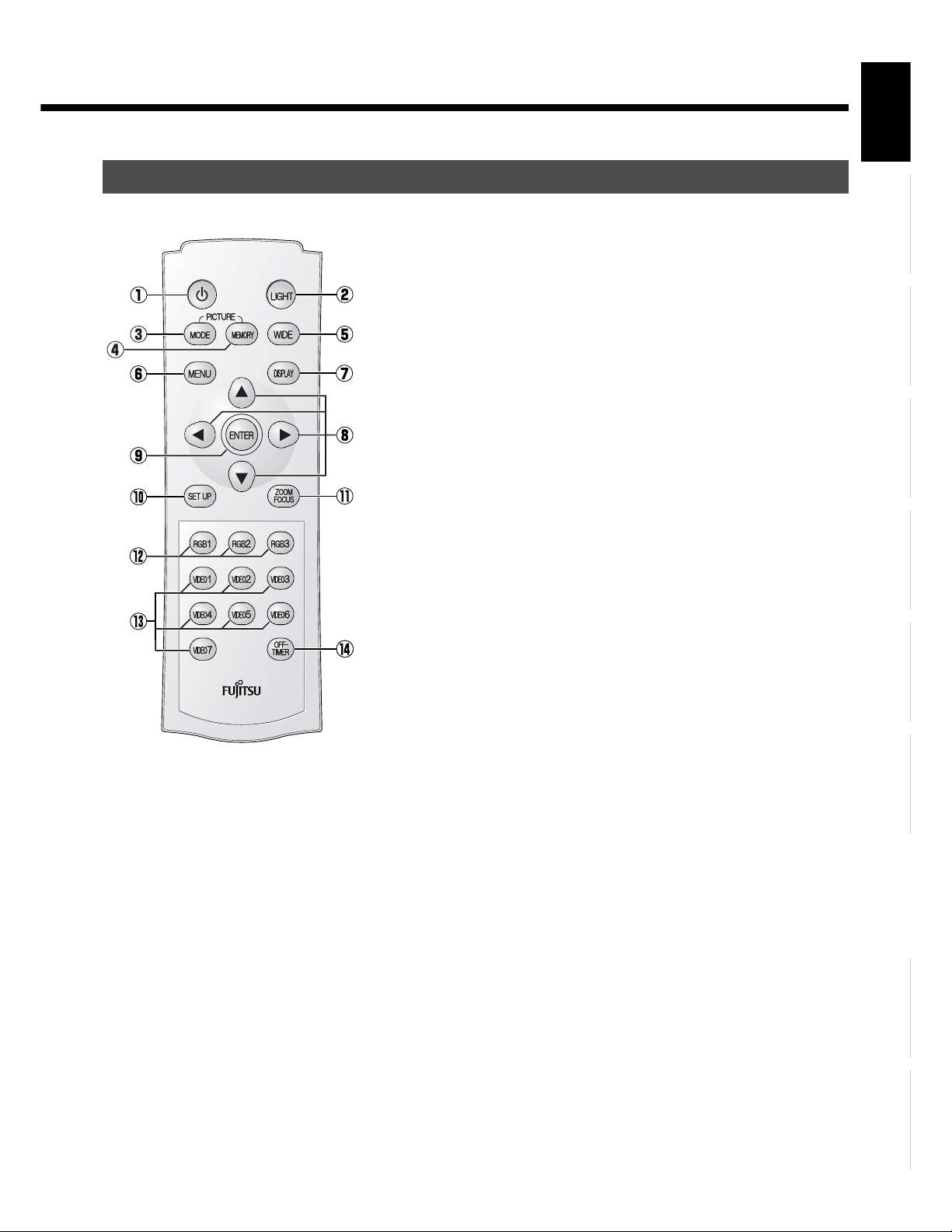
REMOTE CONTROL
For details, see page Î.
button Î E-29
Switches between Power On and Standby.
[ (LIGHT button) Î E-35
Press this button to light up the buttons on the remote control. If the buttons are left
untouched, the light turns off in 7 seconds.
4 (PICTURE MODE button) Î E-35
Use this button to switch the Picture Mode.
5 (PICTURE MEMORY button) Î E-35
Press this button to recall a Picture Memory.
(WIDE button) Î E-36
Switches the screen size.
; (Menu button) Î E-38–E-53
Press this button to display the menu screen for adjusting the picture and/or the audio.
3 (DISPLAY button) Î E-35
Press this button to display the Program No., input mode, and screen size status.
The status is displayed for about five seconds.
CDEF (Adjustment buttons) Î E-38–E-53
Use these buttons to select the item or adjust the value in the Menu screen.
< (Enter button) Î E-38–E-53
Press this button to fix the entry in the ADJUSTMENT MENU.
\ (SET UP button) Î E-35
Press this button to make lens shift, screen reverse and keystone adjustments.
] (ZOOM/FOCUS button) Î E-35
Press this button to adjust the size and focus of the picture.
) – + (RGB input mode selector button) Î E-34
Press this button to switch through RGB1 to RGB3.
" – ( (Video input mode selector button) Î E-34
"
Press this button to switch through VIDEO1 to VIDEO.
7 (OFF-TIMER button) Î E-35
#
Use this button to specify the length of time until the projector goes into standby.
EnglishDeutschEspañolFrançaisItalianoPortuguês
Póññêèé
E-17
Ё᭛
ġུġࢊ
Page 18
USING THE REMOTE CONTROL
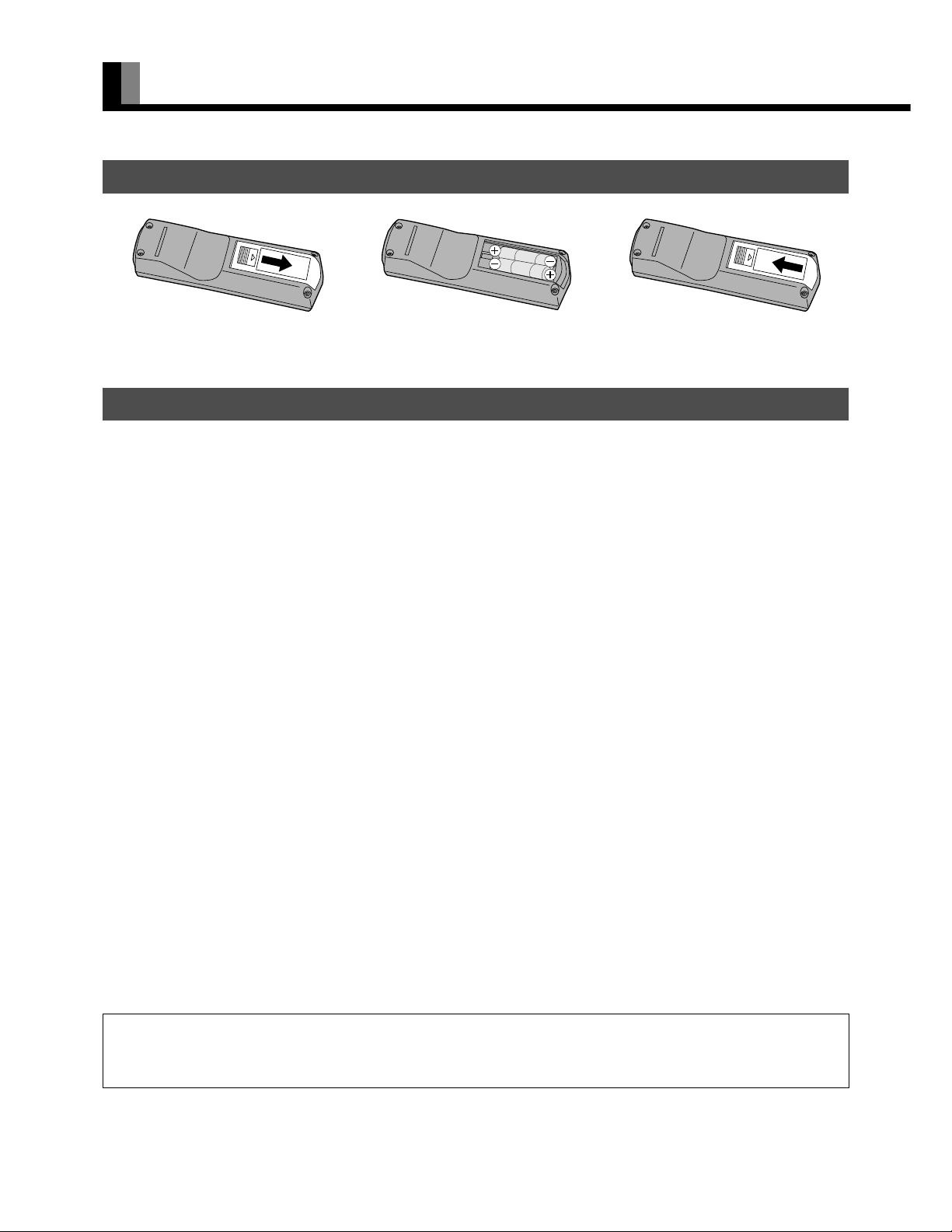
PUTTING BATTERIES IN THE REMOTE CONTROL
(1) To remove the cover, slide it outwards
while pressing it down.
(2) Place two AAA batteries. Pay attention
to set them in correct pole.
(3) Close the cover until it snaps into place.
PRECAUTIONS
To prevent malfunction, be sure not to apply any form of severe shock to the remote control.
To prevent malfunction or deformation, be sure not to allow the remote control to become wet; also, keep it away from hot locations or
heating equipment.
Be sure not to clean the remote control using a cloth dampened in any volatile solvent, such as benzene or thinner.
CAUTION
Be sure to use replacement batteries of the same type as the original ones.
When disposing of used batteries, please comply with governmental regulations or environmental public institution’s rules that apply in your country/
area.
Note
The remote control will not function properly if the batteries are dead. Be sure to replace them as needed.
Do not use rechargeable batteries (Ni-Cd, etc).
E-18
Page 19
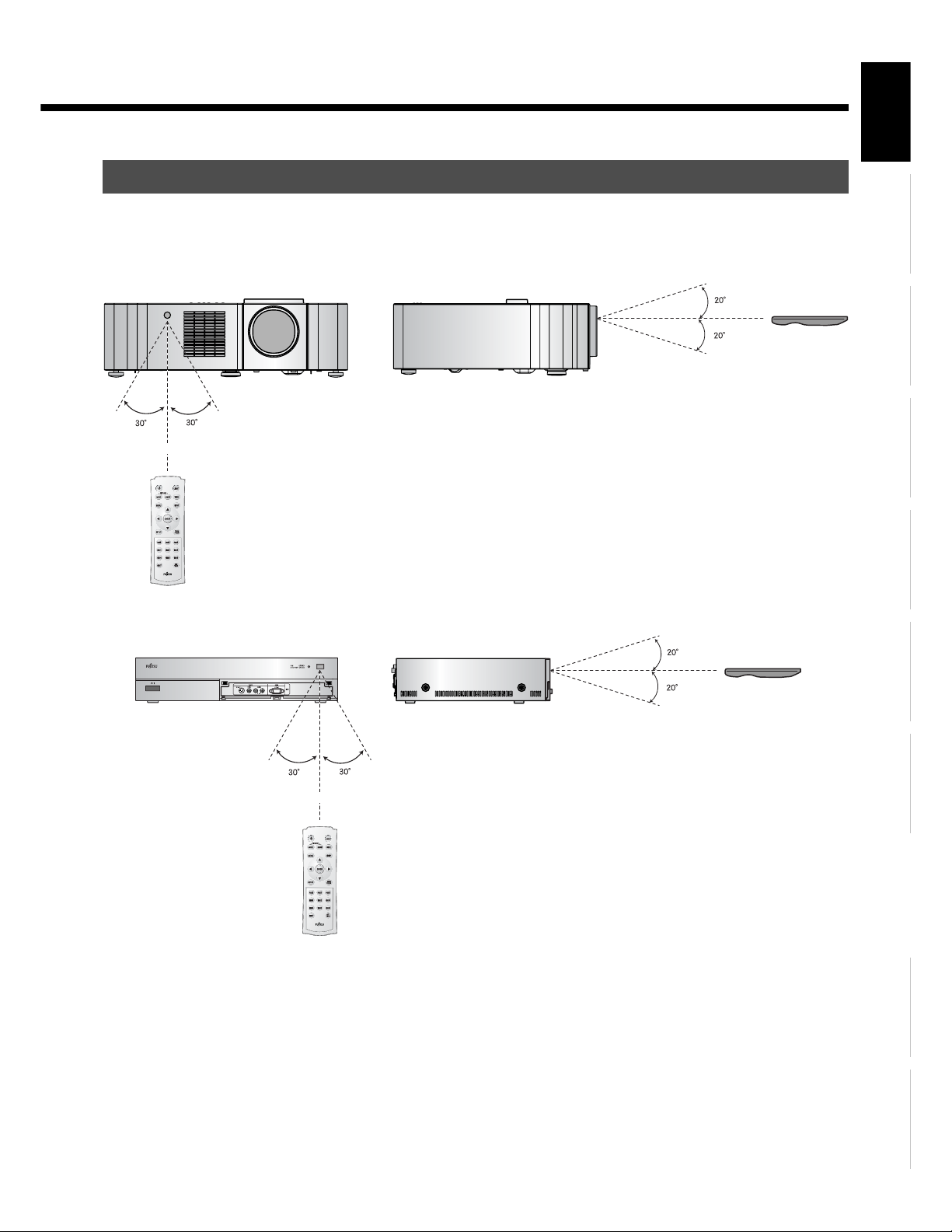
EFFECTIVE RANGE FOR THE REMOTE CONTROL
Point the remote control at the display’s signal receiver when using it.
Make sure that there are no obstacles between the remote control and the display’s signal receiver.
EnglishDeutschEspañolFrançaisItalianoPortuguês
Upper
Lower
Left
Right
5 m (Front)
Upper
Lower
Left Right
5 m (Front)
Póññêèé
Note
The remote control may not function properly if you use a high-frequency fluorescent lamp. If you experience problems, move the lamp or use the
remote control from a different position.
Ё᭛
ġུġࢊ
E-19
Page 20
CONNECTING THE DISPLAY TO EXTERNAL EQUIPMENT
Be sure to turn OFF the power to the display and external equipment before making any connections.
No cables are supplied with the display for connection to external equipment. The type of cable to be used varies depending on the PC
model. Contact your dealer for more information.
Carefully check the terminals for position and type before making any connections.
Loose connectors can result in picture or color problems. Make sure that all connectors are securely inserted into their terminals.
* Never force to bend the power cords or cables. Otherwise they may cause damage.
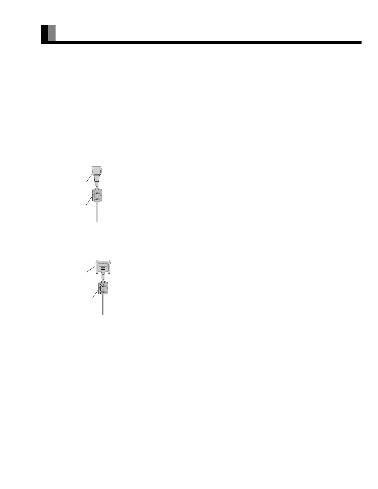
These ferrite cores are used to attenuate undesired signals. Attach them correctly as shown in the following illustrations.
One ferrite core (For AV SELECTOR)
When connecting a cable to the power input terminal, attach one of these ferrite cores to the cable near the terminal.
Power Cable
Ferrite Core
Two ferrite cores (For System Cable)
When connecting the System Cable (PICTURE), attach these ferrite cores to near the both ends of the cable.
System Cable
(PICTURE)
Ferrite Core
E-20
Page 21

CONNECTING THE PROJECTOR AND THE AV SELECTOR
Rear side of projector
Power input terminal
Picture terminal
System cable (PICTURE)
EnglishDeutschEspañolFrançaisItalianoPortuguês
To AC o u t l e t
Picture terminal
Power input terminal
Note
• Never force to bend the power cords or cables. Otherwise they may cause damage.
Rear side of AV selector
Póññêèé
To AC o u t l e t
Ё᭛
ġུġࢊ
E-21
Page 22

CONNECTING THE DISPLAY TO EXTERNAL EQUIPMENT (Continued)
EXAMPLE OF CONNECTION TO EXTERNAL COMPONENTS
The projector unit has no speaker function. To produce sound, connect it to an external amplifier.
Remote control
VCR or other external components See P. Î
VCR Î E-23
DVD recorder/player Î E-24
Satellite tuner Î E-25
Video camera Î E-26
Videogame machine Î E-26
Projector
AV Se l e c tor
To AC outlet
To AC outlet
PC Î E-27
Audio amplifier Î E-28
Note
• Unplug the power cord from the AC outlet before you connect external components.
• Also refer to the instructions for the component to be connected.
• The projector unit has no speaker function. To produce sound, connect it to an external amplifier.
E-22
Page 23

VCR
• Connect the video signal cable to either the S-video input terminal or the video input terminal.
• If the unit to be connected is equipped with S-video output terminal, it is recommended to connect to the S-video terminal.
To video output
To audio outputs
To S-video
output
To audio inputs To video input
EnglishDeutschEspañolFrançaisItalianoPortuguês
To S-video input
Rear side of AV Selector
Póññêèé
Ё᭛
Note
• Unplug the power cord from the AC outlet before you connect external components.
• Also refer to the instructions for the component to be connected.
• When inputting audio, connect to the terminals corresponding to the used video input or RGB input.
ġུġࢊ
E-23
Page 24

CONNECTING THE DISPLAY TO EXTERNAL EQUIPMENT (Continued)
DVD RECORDER/PLAYER
• Connect the picture signal cable to any one of the HDMI input terminal, component picture input terminal, S picture input terminal, or
picture input terminal.
• When the equipment to be connected is equipped with the HDMI output terminal or the component picture output terminal, connection to
either of these terminals is recommended.
To video output
To S-video output
To audio outputs
To S-video input
To HDMI output
To component video output
To audio
inputs
To HDMI input
To video input
Rear side of AV Selector
To component video input
E-24
Page 25

SATELLITE TUNER
• Connect the picture signal cable to any one of the HDMI input terminal, component picture input terminal, S picture input terminal, or
picture input terminal.
• When the equipment to be connected is equipped with the HDMI output terminal or the component picture output terminal, connection to
either of these terminals is recommended.
UHF Antenna
BS/110-degree CS Antenna
To video output
EnglishDeutschEspañolFrançaisItalianoPortuguês
To audio outputs
To HDMI output
To HDMI input
To component video output
To S-video output
To S-video input
To audio
inputs
To component video input
To video input
Póññêèé
Rear side of AV Selector
Ё᭛
Note
• Unplug the power cord from the AC outlet before you connect external components.
• Also refer to the instructions for the component to be connected.
• The projector unit has no speaker function. To produce sound, connect it to an external amplifier.
ġུġࢊ
E-25
Page 26

CONNECTING THE DISPLAY TO EXTERNAL EQUIPMENT (Continued)
VIDEO CAMERA
• A video camera can conveniently be connected to the Video 3 input on the front side.
• Connect the video signal cable to either the S-video input terminal or the video input terminal.
• If the unit to be connected is equipped with S-video output terminal, it is recommended to connect to the S-video terminal.
To video and audio outputs
To S-video output
To S-video input
To video and audio inputs
Front side of AV Selector
VIDEOGAME MACHINE
• As the connecting cable differs with videogame machines, please consult the instructions for your videogame machine.
• Connect the video signal cable to either the S-video input terminal or the video input terminal.
• Ensure that the same image (pattern) is not displayed on the screen for an extended period. If the same image is displayed on the screen for
an extended period, the brightness of that part of the screen may change and image burn-in may leave an after-image on the screen.
• If the videogame machine to be connected is equipped with S-video output terminal, it is recommended to connect to the S-video terminal.
E-26
To video and audio outputs
To S-video output
To video and audio inputs
To S-video input
Front side of AV Selector
Page 27

PC
• As the cable for connecting a PC differs with the PC model, please consult your dealer for information on the right cable to purchase.
• The PC can be connected to either the front side or the rear side, whichever is most convenient.
To RGB output (mD-sub)
To audio output
EnglishDeutschEspañolFrançaisItalianoPortuguês
To RGB output (mD-sub)
To audio output
To RGB output (DVI-D)
To audio input
To mD-sub input
When connecting to the front side of the AV Selector
To audio
input
To DVI-D input
To mD-sub input
Póññêèé
When connecting to the rear side of the AV Selector
Note
• Unplug the power cord from the AC outlet before you connect external components.
• Also refer to the instructions for the component to be connected.
• The projector unit has no speaker function. To produce sound, connect it to an external amplifier.
Ё᭛
ġུġࢊ
E-27
Page 28

CONNECTING THE DISPLAY TO EXTERNAL EQUIPMENT (Continued)
WHEN OUTPUTTING AUDIO SIGNALS TO AN AUDIO AMPLIFIER
• Connect the audio signal cables to the digital output and the analog audio output terminals.
* Connect the audio signal to the digital audio output terminal and analog audio output terminal. For switching over the digital audio output
terminal to the analog audio output terminal, see the audio input selection (page E-50).
* The signal input as digital input is not output as analog audio.
* The digital audio input terminal on the display complies with a sampling frequency of 48 kHz.
In the case of outputs with another frequency, connect to an audio system (amplifier)*.
To digital audio input
To analog audio input
Rear side of AV Selector
To digital audio outputTo analog audio output
E-28
Page 29

BASIC OPERATIONS
TURNIG ON THE POWER
Press "l" side of the ٤ /I button on
1
2
the right hand side of the projector's
rear, and then, press
the left hand side of AV selector's
front.
The power indicator lamps of both the projector and
AV selector light up.
Press .
The color of the power indicator lamp turns from
"Red" to "Green".
(The indicator lamp blinking in orange on the
projector indicates that the lamp is let to cool.)
EnglishDeutschEspañolFrançaisItalianoPortuguês
/I button on
Note
• For one minute after the light source lamp lights up, another press of "POWER" button will not turn off the power.
Póññêèé
Ё᭛
ġུġࢊ
E-29
Page 30

BASIC OPERATIONS (Continued)
TURNING THE POWER TO STANDBY
Press .
1
The confirmation display appears.
Press E to select "OFF".
2
Press <.
3
* You can also use the buttons on
the projector's control panel to
perform these steps.
The projector operates as follows:
(1)The color of the power indicator lamp turns from
green to orange (flashing) to indicate that the
cooling of the light source lamp is in progress.
(2)The cooling fan rotates for 2 minutes. For one
minute after the cooling of the light source lamp
is started, the buttons on the projector and
remote control are disabled, and the light source
lamp cannot be lighted again. (After one
minute, the lamp can be turned on again.)
(3)When the cooling is completed, the fan stops
operation, and then the power monitor indicator
lamp turns on in red, resulting in the "standby"
mode.
* Even after the power is turned to standby mode,
the cooling fan continues rotating while high
temperature remains inside the projector (for
approximately 2 minutes). While the cooling is in
process, do not unplug the power cord from the
receptacle.
* Pressing "POWER" button twice successively
will also turn the power to standby mode.
E-30
Page 31

ADJUSTING THE FOCUS AND SIZE OF THE PICTURE
Press ].
1
2
3
The zoom/focus adjustment menu display appears.
* If the menu screen is out of focus, press
adjust the focus.
Press EF to adjust the focus of the
picture.
Press CD to adjust the size of the
picture.
* Once this button is pressed, the adjustment
operation halts. This means an operation to make
fine-adjustment with ease. Use this function at the
time of fine-adjustment.
* This function does not work beyond the range of
adjustment.
EF to
EnglishDeutschEspañolFrançaisItalianoPortuguês
Zoom/focus adjustment menu
* You can also use the buttons on
the projector's control panel to
perform these steps.
FINE-ADJUSTING THE SCREEN POSITION
Press \.
1
The adjustment menu display appears.
Press CD to select "Lens Shift".
2
Press <.
3
4
The adjustment display appears.
Press EFCD to fine-adjust the
screen position.
* Once this button is pressed, the adjustment
operation halts. This means an operation to make
fine-adjustment with ease. Use this function at the
time of fine-adjustment.
* This function does not work beyond the range of
adjustment.
Póññêèé
Installation menu screen
Ё᭛
* You can also use the buttons on
the projector's control panel to
perform these steps.
ġུġࢊ
E-31
Page 32

BASIC OPERATIONS (Continued)
ADJUSTING THE RECTANGULAR DISTORTION OF THE PICTURE
Press \.
1
The adjustment menu display appears.
Press CD to select "Correct Keystone".
2
Press <.
3
4
The adjustment display appears.
Press EFCD to adjust the
rectangular distortion of the picture.
Installation menu screen
Pressing C corrects the distortion of the upper
portion of the picture.
* You can also use the buttons on
the projector's control panel to
perform these steps.
5
Pressing
portion of the picture.
Pressing
portion of the picture.
Pressing
portion of the picture.
Press < to register the adjustment
result.
D corrects the distortion of the lower
E corrects the distortion of the left side
F corrects the distortion of the right side
Note
• Adjustment of either of the vertical or horizontal axis restricts the adjustment range of the other. (For example, if the horizontal axis is adjusted to the
maximum level. adjustment of the vertical axis will be made impossible.)
• Adjustment with the Keystone button may cause change the aspect ratio. In this case, correct the aspect ratio by adjusting the size.
E-32
Page 33

REVERSING THE PICTURE
Press \.
1
The adjustment menu display appears.
Press CD to select "Reverse Mode".
2
Press <.
3
4
The adjustment display appears.
Press EF to reverse the picture as
desired.
EnglishDeutschEspañolFrançaisItalianoPortuguês
* You can also use the buttons on
the projector's control panel to
perform these steps.
5
Press < to register the adjustment
result.
Installation menu screen
Póññêèé
E-33
Ё᭛
ġུġࢊ
Page 34

SELECTING INPUT MODE
VIDEO INPUT MODE
Press the "-( buttons to select
1
the input mode.
You can select from VIDEO 1 mode to VIDEO 7
mode.
The video modes corresponding to each input
terminal are as follows.
• VIDEO1: Video, S-video, Component video
• VIDEO2: Video, S-video, Component video
• VIDEO3: Video, S-video
• VIDEO4: Video, S-video, Component video
• VIDEO5: Component video
• VIDEO6: Component video
• VIDEO7: HDMI
* For selection of the input terminal, see
“SETTING THE INPUT TERMINALS” on
P. E - 4 9 .
Video1 mode
RGB INPUT MODE
1
Press )-+ to select the input
mode.
You can select between the modes from RGB1 to
RGB3.
The input terminal of each RGB mode is as follows.
• RGB1: DVI-D
•RGB2: mD-sub
•RGB3: mD-sub
RGB1 mode
E-34
Page 35

OTHER BASIC OPERATIONS
CONVENIENT FUNCTIONS
LIGHT button
Press [.
The buttons on the remote control light up.
If the buttons are left untouched, the light turns off in 7 seconds.
On-screen information
Press 3.
The channel or mode is indicated on the screen for 5 seconds.
Picture Mode
Press 4.
This button can be used to switch the picture mode.
In the picture mode, you can switch between the set status and the fine mode.
* For the picture mode settings, see “Setting Picture Mode (P. E-40)”.
Picture Memory
EnglishDeutschEspañolFrançaisItalianoPortuguês
Press 5.
This button can be used to recall the settings of the picture memories 1 – 8. Each time this button is
pressed, the setting changes as follows.
* For the method of storing the picture adjustment settings in memory, see "Picture Memory" on page
E-41.
ZOOM/FOCUS button
Press ].
The size and focus of the picture can be adjusted.
* See the section "ADJUSTING THE FOCUS AND SIZE OF THE PICTURE" (page E-31) for setting
zoom and focus.
SET UP button
Press \.
The lens shift, screen reverse and keystone adjustments can be made.
* For projector installation position adjustment, see the sections "FINE-ADJUSTING THE SCREEN
POSITION" (page E-31), "ADJUSTING THE RECTANGULAR DISTORTION OF THE PICTURE"
(page E-32), and "REVERSING THE PICTURE" (page E-33).
OFF-timer
Press 7.
This can be used to set the time before the power is turned off. Each time this button is pressed, the setting
changes as follows.
Póññêèé
Ё᭛
E-35
ġུġࢊ
Page 36

WATCHING PICTURES ON THE WIDE SCREEN
SWITCHING BETWEEN SCREEN SIZES
Press .
1
2
The currently selected mode will appear.
Press to select a desired Screen
Size.
Each time you press , a different Screen Size
appears. The sequences used are as follows:
When you are in a Video input mode
When you are in an RGB input mode
* Depending on the type of signal, some aspects
may not be selected.
Normal mode
Wide1 mode
Note
• Displaying a picture in a Normal mode for extended periods of time may cause phosphor burn-in.
• A variety of Screen Sizes are available with this display. Remember that if you select a mode with an aspect ratio (ratio of frame width to frame
height) different from that of the TV program or video media, the pictures will appear differently than if you had selected a mode having the same
aspect ratio.
• Showing a movie or similar premium event at a different aspect ratio from its original one at any event site, restaurant, or bar for profit-making
purposes or for a public audience may constitute a copyright infringement.
For films, try to select a mode having the same aspect ratio as the original picture; this enables the director ’s original intentions to be preserved.
E-46 for how to adjust the picture size and position.
•See P.
E-36
Page 37

SCREEN SIZE
Normal (Video/RGB)
Displays pictures of normal size (i.e., a 4:3 aspect ratio).
Wide1 (Video)
Displays natural-looking pictures of standard size on the wide screen.
EnglishDeutschEspañolFrançaisItalianoPortuguês
Wide2 (Video)/Wide (RGB)
Ideal for displaying vertically extended pictures such as squeezed pictures.
Zoom1 (Video)/Zoom (RGB)
Enlarges horizontally extended pictures equally in all directions to maintain the aspect
ratio constant.
Zoom2 (Video)
Reduces the height of horizontally extended pictures with captions, without eliminating
the caption. Only the height of pictures is reduced, not the height of the caption.
(Captions may not be easy to read, however, depending on the picture.)
ASPECT RATIO
The following aspect ratios are available.
4:3 aspect ratio 16:9 aspect ratio
(VHF/UHF broadcasting, BS broadcasting) (HDTV broadcasting)
3
4
Picture of
standard size
Vertically
extended picture
Horizontally
extended picture
Horizontally extended
picture with caption
Wide1
Wide2
Zoom1
Zoom2
16
9
Póññêèé
1.85:1 aspect ratio 2.35:1 aspect ratio
(Vista Vision size) (Cinema Vision size)
1
Note
• You may find dark areas on top and at the bottom of the screen if you select one of the Zoom modes for media while using the Vista Vision or Cinema
Vision size i.e., the sizes used frequently for picture software.
• The picture in 1080i format will be slightly reduced in size on the wide screen.
1.85
2.35
1
E-37
Ё᭛
ġུġࢊ
Page 38

ADJUSTMENT MENU
The numbers in parentheses ( ) indicate the reference page numbers.
PICTURE (E-39) Signal Contrast (E-40)
MENU
POSITION/SIZE (E-46) Drive Contrast (E-40) Black Level (E-42)
FEATURES (E-47) Brightness (E-40) Detail Gradation (E-42)
FACTORY DEFAULT(E-53)
Color (E-40) 3D NR (E-42)
Tint (E-40) CODEC NR (E-42)
Sharpness (E-40) Image Enhance (E-43) Image identify (E-43)
Picture Mode (E-40) Color Temp. (E-43)
Lamp (E-40) User Color Temp. (E-43)
Light Control (E-41) Color Focus (E-44)
PrecisionSetting (E-41) Progressive Scan (E-45) 24 Frame Mode (E-45)
Picture Memory (E-41) 30 Frame Mode (E-45)
Default Jaggies Filter (E-45)
Position (E-46)
Size (E-46)
Default Reverse Mode (E-33)
Set Up (E-35) Correct Keystone (E-32)
Zoom/Focus (E-35) Lamp Timer (E-57)
Adjustment (E-47)
On Screen Menu (E-48) Dot Clock (E-47)
Input Terminal (E-49) Clock Phase (E-47)
Others (E-50) Clamp Position (E-47)
Motion Setting (E-45)
Lens Shift (E-31)
Auto Calibration (E-47)
OSD (E-48)
Language (E-48)
Name Select (E-48)
Video1 (E-49)
Video2 (E-49)
Video3 (E-49)
Video4 (E-49)
Auto Off-NO SIG. (E-50)
Audio Input (E-50)
Direct Setting (E-51) HDMI input (E-50)
Code Setting (E-51)
Blank Screen (E-51)
Exhibition Mode (E-51)
Information (E-52)
Except HDMI input
(E-50)
E-38
Page 39
BASIC PROCEDURE OF ADJUSTMENT MENU OPERATIONS
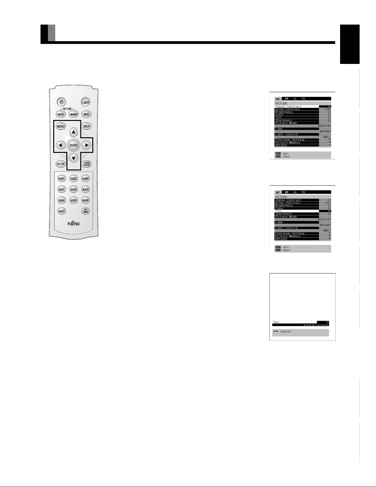
• Below is shown the basic procedure to make changes to the options in the ADJUSTMENT MENU. (Ex.: adjusting tint setting (Tint))
• Select an input mode to be set on the PICTURE screen. (Store adjustment contents to be set for each input mode.)
Press ;.
1
The main menu screen will appear.
Press E or F to select “PICTURE”.
2
Each time you press E or F, one of the available
menus appears in the following sequence:
PICTURE < POSITION/SIZE < AUDIO < FEATURES <
FACTORY DEFAULT
The PICTURE Menu screen will appear.
Press C or D to select “Tint”.
“PICTURE” selected in the main
menu screen
3
Press <.
4
The “Tint” adjustment screen will appear.
EnglishDeutschEspañolFrançaisItalianoPortuguês
“Tint” selected in the PICTURE
Menu screen
Press E or F to change tint values.
5
F: More greenish colors
E: More purplish colors
Press < to store.
6
Press ; when you finish.
7
* Repeat steps 3, 4, 5 and 6 when you wish to make
changes to other options.
* When
< is pressed after you have selected
“Default”, the settings are returned to those that
were valid when you purchased the set.
* Press
; to halt the operation in progress.
Note
• On-screen information disappears if you do not take any action for about 60 seconds.
• Functions may not be available with some models and some device options.
• The adjustment range varies with the display signal. You can adjust the display quality to the value you want within the adjustable range.
• Depending on the type of signal, it may not be possible to make some of the settings or adjustments.
“Tint” adjustment screen
Póññêèé
Ё᭛
ġུġࢊ
E-39
Page 40

ADJUSTING THE PICTURE
• Picture-related items can be set and adjusted in the Picture Adjustment Screen. See BASIC PROCEDURE OF ADJUSTMENT MENU
OPERATIONS on page E-39 for the basic operation procedures.
Adjusting the Signal Contrast
Press F to increase the input signal contrast.
E to reduce the input signal contrast.
Press
Press
< to store.
Adjusting the Drive Contrast
Press F The illumination level rises and the contrast increases over all gradation.
E The illumination level lowers and the contrast reduces over all gradation.
Press
Press
< to store.
Adjusting the Brightness
Press F to increase the brightness.
Press
E to reduce the brightness.
< to store.
Press
Adjusting Color
Press F to darken the color.
E to lighten the color.
Press
< to store.
Press
Adjusting the Tint
Press F to change the tint to a more greenish color.
E to change the tint to a more purplish color.
Press
Press
< to store.
Adjusting the Sharpness
Press F to sharpen the Sharpness.
E to soften the Sharpness.
Press
< to store.
Press
Setting the Picture Mode
Picture mode changes by pressing E or F, and the optimumǫ-curve for each picture mode shall
be set up automatically.
[Natural]: Displays a screen with detailed contrast.
[Fine]: Suitable for watching a dark picture such as a movie.
[Effective]: Enables you to watch pictures with natural color tones and high picture clarity.
This mode is suitable for watching a normal motion picture.
[Conventional]: Similar picture to CRT screen.
[Still]: Suitable for viewing a still picture.
Press
< to store.
Setting the luminance of the light source lamp
Each time you press E or F, the luminance of the light source lamp changes over.
Normal <9Low
[Normal]: The luminance of the lamp is set at the standard level.
[Low]: The luminance of the lamp is lowered. This setting can reduce the power consumption of
the lamp to save energy.
Press
< to store.
E-40
Page 41

Setting the intensity of the light source lamp
By adjusting the intensity of the light source lamp according to the brightness of the picture, the contrast of the moving picture can be
optimally enhanced.
Each time you press
Off Min. Mid. Max.
Press
< to store.
E or F, the intensity of the light source lamp changes over in the following sequence.
Precision Setting
Enables advanced Sharpness adjustments.
See page E-42 for details.
Picture Memory
The adjustment status of eight groups of picture adjustment settings can be stored, enabling you to
quickly switch to your desired group of settings for the picture you are planning to watch.
Picture Memory Selection Screen
[Save]: Use
values are stored to the selected Memory.
C or D to select Memory 1 - 8. If < is pressed, the current picture adjustment
EnglishDeutschEspañolFrançaisItalianoPortuguês
[Load]: Use
adjustment values stored in the selected Memory.
* When the projector unit is shipped out of the factory, the following recommended settings are stored
in the picture memories 4-8.
Picture memory 4: Suitable for viewing the picture of PC.
Picture memory 5: Similar picture to CRT screen.
Picture memory 6: Suitable for viewing normal moving picture.
Picture memory 7: Suitable for viewing a dark picture such as movies.
Picture memory 8: Suitable for viewing digital broadcast and sports programs.
New settings can be stored in the picture memories 4-8. By performing "FACTORY DEFAULT" (see
page E-53), however, the recommended settings can be restored in respective picture memories.
Note
• The screen display disappears if there is no operation within approximately 60 seconds.
• Depending on the model or the optional devices, some of the functions may not be available.
• The adjustment range varies according to the display signals. Make adjustments to your preferred Sharpness within the adjustment range.
• Depending on the type of signal, it may not be possible to make some of the settings or adjustments.
C or D to select Memory 1 - 8. When < is pressed, the values becomes the picture
“Save” Selection Screen
“Load” Selection Screen
Póññêèé
Ё᭛
ġུġࢊ
E-41
Page 42

ADJUSTING THE PICTURE (Continued)
PRECISION SETTING
• See BASIC PROCEDURE OF ADJUSTMENT MENU OPERATIONS on page E-39.
Even more advanced Sharpness adjustments can be made as required.
Adjusting the Black Level
Press F to strengthen the reproduction of black. (Provides a picture quality with deep blacks.)
E to weaken the reproduction of black.
Press
< to store.
Press
Setting Detail Gradation
Corrects the gradation of the light and dark areas of the picture.
Each time
Press
Setting 3D NR
This enables noise reduction processing with respect to the input signal noise level (reduces screen
flicker for more comfortable viewing).
Each time you press
E or F is pressed, the setting is switched.
On < Off
< to store.
E or F, the available choices appear in the following sequence.
Precision Setting Selection
Screen
Press
< to store.
Setting CODEC NR
This enables noise reduction processing of mosquito noise or block noise generated when digital picture
signals are recorded or replayed.
Each time you press
< to store.
Press
E or F, the available choices appear in the following sequence.
E-42
Page 43

Setting Image Enhance (Valid in the DVI-D mode only)
This performs detailed image quality settings.
• Image Identify
This function discerns between the natural image display section and the text display section, and performs correction to enable an
optimized display for each.
Each time
Press
Adjusting the Color Temp.
Use E or F to specify a desired color temperature. Each time you press E or F, one of the available choices appears in the
following sequence:
Press
Setting User Color Temp.
Use C or D to select Red, Green, or Blue, and adjust the color temp. for each.
Press
Press
Press
E or F is pressed, the setting is switched.
On < Off
< to store.
[–3500]:More reddish colors
[+3500]:More bluish colors
[User]:User Color Temp. setup
<: to store.
F: to strengthen the selected color.
E: to weaken the selected color.
< to store.
EnglishDeutschEspañolFrançaisItalianoPortuguês
Note
• The screen display disappears if there is no operation within approximately 60 seconds.
• Depending on the model or the optional devices, some of the functions may not be available.
• The adjustment range varies according to the display signals. Make adjustments to your preferred Sharpness within the adjustment range.
• Depending on the type of signal, it may not be possible to make some of the settings or adjustments.
Póññêèé
Ё᭛
ġུġࢊ
E-43
Page 44

ADJUSTING THE PICTURE (Continued)
Setting the Color Focus
This enables correction with respect to specific color hues within the image.
Independent correction of the hue of skin colors, blue skies, and so on, enables a more brilliant display.
• [Reddish color]
With red at the center, performs the following corrections with respect to the range from magenta to
yellow.
[Tint]: Use
[Color]: Use
[Red]: Use
[Green]: Use
[Blue]: Use
Press
Adjustments can be made in the same way for:
• [Greenish color]: (With green at the center, performs corrections with respect to the range from yellow to cyan.)
• [Bluish color]: (With blue at the center, performs corrections with respect to the range from cyan to magenta.)
• [Targeting Red]
This function corrects the hue and color depth with respect to Red.
[Tint]: Use
[Color]: Use
Press
E and F to adjust the hue.
E and F to adjust the color depth.
E and F to adjust the strength of the red color range.
E and F to adjust the strength of the green color range.
E and F to adjust the strength of the blue color range.
< to store.
E and F to adjust the hue.
E and F to adjust the color depth.
< to store.
Color Focus (Reddish color)
Settings Screen
Adjustments can be made in the same way for:
• [Targeting Yellow] (Performs correction with respect to Yellow.)
• [Targeting Green] (Performs correction with respect to Green.)
• [Targeting Cyan] (Performs correction with respect to Cyan.)
• [Targeting Blue] (Performs correction with respect to Blue.)
• [Targeting Magenta] (Performs correction with respect to Magenta.)
• [Targeting White]
Corrects red, green, and blue with respect to white.
[Red]: Use
[Green]: Use
[Blue]: Use
Press
E and F to adjust Red.
E and F to adjust Green.
E and F to adjust Blue.
< to store.
E-44
Page 45

Making the Progressive Scan Settings
This sets the conversion processing of interlace signals to block receive signals.
• 24 Frame Mode
This function enables the optimized display of movies, etc. with 24 frames/second signals.
Each time
Press
• 30 Frame Mode
This function enables the optimized display of movies, etc. with 30 frames/second signals.
Each time
Press
• Jaggies Filter
This function alleviates the phenomenon where jagged diagonal lines can be seen when interlace
signals are input, thus enabling a smoother motion picture display.
Each time
Press
E or F is pressed, the setting is switched.
Auto < Off
< to store.
E or F is pressed, the setting is switched.
Auto < Off
< to store.
E or F is pressed, the setting is switched.
Auto < Off
< to store.
EnglishDeutschEspañolFrançaisItalianoPortuguês
Progressive Scan Settings
Screen
• Motion Setting
The detecting sensitivity for motion picture is set.
The response of the picture processing is valued in the motion picture priority setting.
F: to specify still picture priority.
Press
E: to specify motion picture priority.
Press
< to store.
Press
Note
• The screen display disappears if there is no operation within approximately 60 seconds.
• Depending on the model or the optional devices, some of the functions may not be available.
• The adjustment range varies according to the display signals. Make adjustments to your preferred Sharpness within the adjustment range.
• Depending on the type of signal, it may not be possible to make some of the settings or adjustments.
Póññêèé
Ё᭛
ġུġࢊ
E-45
Page 46
ADJUSTING SCREEN POSITION AND SIZE
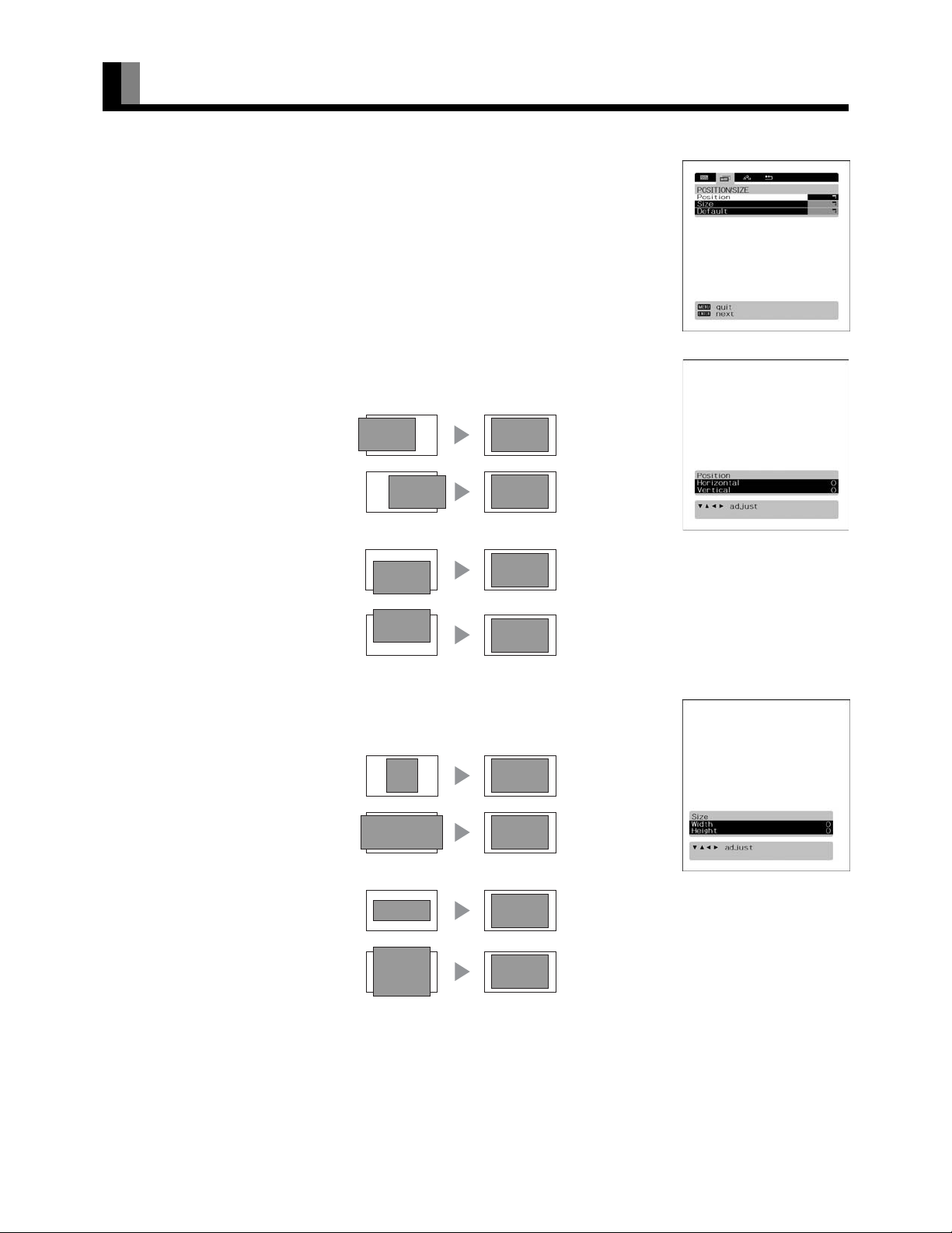
• You can make changes to all screen adjustment options in the POSITION/SIZE Menu. See Page
E-39 for the basic operation procedures.
• The changes you make will be stored for the selected input mode. Therefore, you need to select a
desired input mode before making any changes.
* The adjustment range may differ depending on the input signal.
Adjusting Screen Position (Position)
Horizontal position (Horizontal)
F: Moves screen to the right.
E: Moves screen to the left.
POSITION/SIZE Menu screen
Vertical position (Vertical)
C: Moves screen up.
D: Moves screen down.
< to store.
Press
Adjusting Screen Size (Size)
Screen width (Width)
F: Increases width.
E: Reduces width.
Screen height (Height)
C: Increases height.
D: Reduces height.
“Position” adjustment screen
“Size” adjustment screen
Press
< to store.
*You cannot adjust screen size in DVI-D mode.
E-46
Page 47

OTHER ADJUSTMENTS
• FEATURES setup screen has the following 6 options.
See Page E-39 for the basic operation procedures.
[Set Up]: Can make lens shift, screen reverse and keystone adjustments. (See P. E-35.)
[Zoom/Focus]: Can adjust the size and focus of the picture. (See P. E-35.)
[Adjustment]: Can make a fine adjustment of pictures such as Dot Clock, Clamp Position. (See P. E-47.)
[On Screen Menu]: Can make a display setting such as OSD, Language. (See P. E-48.)
[Input Terminal]: Can make an input terminal setting such as Video Input. (See P. E-49.)
[Others]: Used to make Screen Orbiter and other settings. (See P. E-50–E-52.)
ADJUSTMENT
Dot Clock, Clock Phase, Clamp Position, and Auto Calibration are adjusted as shown in the following chart.
Select the item with
Adjustment Item Contents of Adjustments Operation
Dot Clock
(mD-sub)
Clock Phase
(mD-sub)
Clamp Position
(mD-sub Comp.
video)
Auto Calibration
(mD-sub)
CD , and then adjust with EF. Finally, press < to implement the adjustments.
You may find the vertically-striped pattern in pictures,
depending on the clock frequency of your PC’s processor.
If you experience blurring, you can obtain a clearer picture by
adjusting the “Dot Clock”.
Pictures and the outline of letters may blur or flicker as the
clock phase of your PC may be different. In this case, adjust the
clock phase manually. Normally, the automatic setting ensures
the optimal value.
Adjusts the extremely dark or bright pictures. Normally, the
automatic setting ensures the optimal value.
Adjusts the dynamic range of images to the optimum.
Performed while a white screen signal is received.
EF to adjust to minimize vertically-
Use
striped pattern in pictures.
Use
EF to adjust to minimize pictures blur.
EF to adjust pictures optimally.
Use
Display the Auto Calibration screen and select
Execute, and then use
item.
CD to select the
EnglishDeutschEspañolFrançaisItalianoPortuguês
E-47
Póññêèé
Ё᭛
ġུġࢊ
Page 48

OTHER ADJUSTMENTS (Continued)
ON SCREEN MENU
• Setting Display Information (OSD)
You can use this option to select whether to display information other than menus. (Error messages are
displayed regardless of what choice you make for this option.)
Each time you press
[On (OSD:bright)]: On-screen information shown in light color.
[On (OSD:dark)]: On-screen information shown in dark color.
[Off]: Except for menus and error messages, on-screen information is not displayed.
Press
< to store.
* When the screen is white [On (OSD:dark)], some of the information may be difficult to read.
• Selecting Language (Language)
You can use this option to select the language displayed on the screen.
(1) Select “Language” and press
The “Language” selection screen will appear.
(2) Press
(3) Press
• Selection of indications (Name Select)
You can change the settings for indications for video inputs and RGB inputs.
Video input
You can change the settings for indications for the VIDEO inputs.
Select the desired indication in accordance with the connected equipment.
Each time
C or D to select your desired language.
ᣣᧄ⺆ (Japanese)
English
Deutsch (German)
Español (Spanish)
Français (French)
Italiano (Italian)
Português (Portuguese)
Русский (Russian)
<.
The menu is displayed in the selected language.
EF is pressed, the setting is switched. (In the case of VIDEO1)
E or F, one of the available choices appears in the following sequence:
<.
OSD selection screen
“Language” selection screen
< to store.
Press
RGB input
You can change the settings for indications for the RGB inputs.
Select the desired indication in accordance with the connected equipment.
Each time
Press
Note
• The screen display disappears if there is no operation within approximately 60 seconds.
• Depending on the model or the optional devices, some of the functions may not be available.
• The adjustment range varies according to the display signals. Make adjustments to your preferred Sharpness within the adjustment range.
• Depending on the type of signal, it may not be possible to make some of the settings or adjustments.
EF is pressed, the setting is switched. (In the case of RGB 1)
< to store.
E-48
Page 49

SETTING THE INPUT TERMINALS
• Selecting the settings of Video Input terminal (VIDEO1-4)
Select the video input format.
Each time
Press
* When Auto is selected, and multiple inputs are present, the inputs will have priority in the order of
Component Video, S-video, and Video.
* Component video input is not made to Video 3.
Video Format
You can use this option to select the video format appropriate for the input signal.
Each time you press
Press
EF is pressed, the setting is switched.
VideoAuto S-video Comp. video
[Auto]: The terminal to which the signal is input is autmatically recognized.
[Other than Auto]: Select the desired input.
< to store.
E or F, one of the available modes appears in the following sequence:
[Auto1]: Automatically selects NTSC, PAL and SECAM.
[Auto2]: Automatically selects NTSC and M-PAL.
[Other than Auto]: You need to select a system appropriate to the input signal.
< to store.
EnglishDeutschEspañolFrançaisItalianoPortuguês
Input Terminal Settings Screen
E-49
Póññêèé
Ё᭛
ġུġࢊ
Page 50

OTHER ADJUSTMENTS (Continued)
OTHER SETTINGS
Auto Off-NO SIG.
If there is no video signal for 10 minutes, the power supply is automatically placed in the standby mode.
Each time
Press
Audio input selection
The input audio signal can be switched over from analog to digital.
Each time
When other than HDMI input is selected:
When HDMI input is selected:
Press
EF is pressed, the setting is switched.
Off < On
< to store.
E or F is pressed, the input signal changes in the following sequence.
Analog Digital 1 Digital 2
HDMI Digital 1 Digital 2
< to store.
Auto Off-NO SIG. settings
screen
"Audio Input signal" selection
screen
E-50
Page 51

• Setting RGB Input Signal Compulsorily (Direct Setting) for RGB
You can use this option to switch the setting for RGB input signal.
Each time you press
[Auto]: The optimum display is obtained automatically for input signals.
[Others]: The optimum resolution setting is fixed for each signal.
< to store.
Press
* In Auto mode, the resolution of VGA, WVGA, 480P, XGA, WXGA, SXGA and SXGA
automatically distinguished. Switch to the fixed display when the image is not displayed properly.
* Signals that are not applicable depending on the model or input terminals may not be displayed.
• Specifying RGB Input Signal (Code Setting) for mD-sub input
Normally, use this option in Auto mode.
• Changing background color to blue (Blank Screen)
When no picture signal is input, the background color can be changed to blue.
Each time
Press
• Setting Exhibition Mode (Exhibition Mode)
You can use this option to display the enhanced contrast, to demonstrate the projector's bright, high
contrast picture.
Each time you press
Press
* In Exhibition mode, the display returns to the original setting in about 5 minutes even if the adjustment is changed.
* The setup will be cancelled when removing the power plug from the receptacle.
E or F is pressed, the background color changes over.
Black Blue
< to store.
On < Off
< to store.
E or F, one of the available choices appears in the following sequence:
+
may not be
E or F, one of the available choices appears in the following sequence:
EnglishDeutschEspañolFrançaisItalianoPortuguês
Note
• The screen display disappears if there is no operation within approximately 60 seconds.
• Depending on the model or the optional devices, some of the functions may not be available.
• The adjustment range varies according to the display signals. Make adjustments to your preferred Sharpness within the adjustment range.
• Depending on the type of signal, it may not be possible to make some of the settings or adjustments.
Póññêèé
Ё᭛
ġུġࢊ
E-51
Page 52

OTHER ADJUSTMENTS (Continued)
• Displaying System Status (Information)
Displays system operation status.
Select “Information” and press
The “Information” screen will appear.
[Mode]: Input mode appears at the upper right corner of the screen
[Freq. Scan Mode]: Frequency scanning
[Input Signal]: Video mode
[Input Sync.]: Signal type
[Freq.]: Synchronized signal frequency, polarity
[Preset No.]: RGB code number
<.
Information screen (Video Mode)
Information screen (RGB Mode)
E-52
Page 53

INITIALIZATION OF USER ADJUSTMENT VALUE
You can restore the values of the adjustment/setting made in the MENU to factory settings.
Press ;.
1
2
The main menu screen will appear.
Press E or F to select “FACTORY
DEFAULT”.
Each time you press E or F, one of the available
menus appears in the following sequence:
PICTURE < POSITION/SIZE < AUDIO < FEATURES <
FACTORY DEFAULT
The FACTORY DEFAULT Menu screen will appear.
Press <.
“FACTORY DEFAULT” selected
in the main menu screen
3
• Displays the message of whether to proceed with the
initialization.
EnglishDeutschEspañolFrançaisItalianoPortuguês
4
5
6
Press C or D to select the Yes.
Displays the message of
whether to proceed the
initialization
Press <.
• The message "Existing data are cleared." is
displayed.
* The screen is displayed in English language.
Póññêèé
Press ; when you finish.
Displays the message of having
completed the initialization
Note
• The screen display disappears if there is no operation within approximately 60 seconds.
• Depending on the model or the optional devices, some of the functions may not be available.
• The adjustment range varies according to the display signals. Make adjustments to your preferred Sharpness within the adjustment range.
• Depending on the type of signal, it may not be possible to make some of the settings or adjustments.
Ё᭛
ġུġࢊ
E-53
Page 54

CLEANING AND MAINTENANCE
Warning
• Do not remove any screws other than those specified (" χ " mark).
The high voltage and high temperature inside the projector may lead to electric shock or burns if touched.
PRECAUTIONS ON AIR FILTERS AND LAMP PROTECTION FILTER
• If the ventilation holes become blocked, the temperature inside the projector rises and the lamp will fail to light. Clean the ventilation
holes about once every 6 months. Cleaning will be required more frequently if used in a particularly dusty environment.
• When the air filter of the ventilation hole becomes hard to clean, it is ready to be changed. Purchase a new air filter (with the filter
holder).
• Do not use the projector with the filter holder detached, as dust and debris may get into the projector, causing them to appear on the
projected screen.
CLEANING THE AIR FILTERS AND LAMP PROTECTION FILTER
Unplug the power cord from the
1
receptacle.
2
3
4
5
Turn the projector upside down.
Pay attention to avoid scratches over the cover by laying a
thick towel and other soft cloth under the projector.
Remove the two screws marked with
" χ ", and take out the lamp protection
filter.
Clean the air filters and lamp protection
filter.
Vacuum-clean the filters.
To do so, be sure to attach a brush to the hose of the vacuum
cleaner.
Reverse the disassembling procedure
above to set the lamp protection filter in
position.
Lamp protection filter
Air filter
Note
• Be sure to use the vacuum cleaner with a brush attached to its hose.
• Application of strong suction power may damage to the filter.
E-54
Page 55

REPLACING THE AIR FILTERS
EnglishDeutschEspañolFrançaisItalianoPortuguês
1
2
3
4
5
Unplug the power cord from the
receptacle.
Turn the projector upside down.
Pay attention to avoid scratches over the cover by laying a
thick towel and other soft cloth under the projector.
Unscrew three screws marked " χ "
symbol to remove the filter holder.
Replace the air filters with new ones.
Replace the two filters together at a time.
Reverse the disassembling procedure
above to set the filter holder in position.
Remove three screws.
Replace air filters with new ones.
CARE OF THE CABINET
To remove dust, wipe the cabinet lightly with a soft dry cloth. If it is heavily soiled, wipe off the soil with a cloth soaked in a solution of
detergent and water and squeezed tightly. Then, use a soft dry cloth to finish cleaning.
CARE OF THE LENS
To clean the lens, use a blower and lens cleaning tissue available on the market for cleaning camera lens. Do not use tissue paper, as it may
scratch the lens. The surface of the lens easily gets scratched, and do not rub or tap it with a hard object.
E-55
Póññêèé
Ё᭛
ġུġࢊ
Page 56
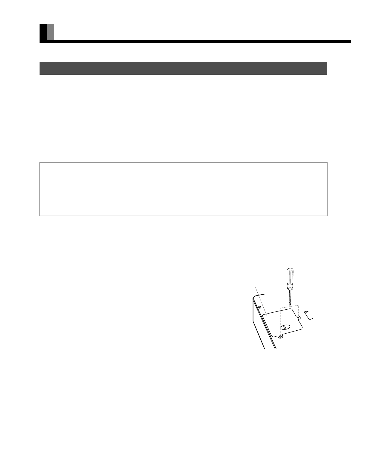
CLEANING AND MAINTENANCE (Continued)
CHANGING THE LAMP
• Lamp life differs according to the lamp and the environment it is used in. The lamp may explode immediately after starting use.
• When the lamp reaches the end of its service life, the image becomes dark and the colors lose their vividness. When this happens, change
the lamp unit.
• Replace with a new lamp unit when the replace lamp message appears. The old lamp may explode if it continues to be used.
• After removing the old lamp unit, handle with care to avoid breakage. Dispose of used lamp units as industrial waste and comply with
governmental regulations or environmental public institution's rules that apply in your country/area.
• Be sure to initialize the lamp timer after changing the lamp unit.
• When replacing the lamp unit, insert it securely. Otherwise, it may damage.
Warning
• Do not remove any screws other than those specified (" χ " mark).
The high voltage and high temperature inside the projector may lead to electric shock or burns if touched.
• When replacing the lamp unit, use only a new replacement lamp unit (LPF-QLD1WW [optional]). Using undesignated, used or second-hand lamp
units may result in the lamp exploding or cause malfunctions.
• Allow the lamp to cool for more than 1 hour after switching off the power before changing.
• This lamp employs a mercury lamp with high internal pressure. It may break with a large bang depending upon shock or service time because of its
property, or the time until the lamp has been worn out differs according to individual difference or service condition.
1
2
3
Unplug the power cord from the receptacle.
To turn off the power, see "TURNING THE POWER TO STANDBY" on page E-30.
Turn the projector upside down.
Lay a thick towel and other soft cloth under the projector lest it should get scratched.
Remove the two screws marked with " χ ", and
then, hold the knob of the lamp unit cover to remove
it from the projector.
To ensure safety, the safety device prevents the power from being turned on
accidentally during the lamp replacement work.
Lamp unit cover
Remove two screws.
E-56
Page 57

4
EnglishDeutschEspañolFrançaisItalianoPortuguês
Loosen two screws on the lamp unit to pull out it.
The lamp unit is so constructed that the screws cannot be detached from it.
Loosen two screws.
5
6
Reverse the disassembling procedure above to set
the lamp unit and lamp unit cover in position.
Check that the lamp unit is installed securely.
After inserting the power plug into the receptacle,
press "ENTER" button, and then, press "POWER"
button five times.
At this time, all monitor indicator lamps blink for a few seconds.
The lamp timer is initialized to "0".
* When replacing the lamp unit, do not touch the glass inside the projector.
Dust and fingerprints sticking to the glass may deteriorate the luminous
intensity of the light source lamp and shorten its life.
Replace lamp unit with a new one.
Póññêèé
Ё᭛
Note
• For replacement, be sure to use a lamp unit specified by the manufacturer only. Otherwise, failure of the lamp to light up, and explosion or damage
of the lamp will result.
• Turn on the light source lamp, and press
\ to select the lamp timer. Check that "0" is set for the lamp timer. Otherwise, initialize the timer again.
E-57
ġུġࢊ
Page 58

CLEANING AND MAINTENANCE (Continued)
Precautions
Be sure to remove the power plug from the receptacle before cleaning the display.
Be sure not to clean the display using a cloth dampened with volatile solvents, such as benzene or thinner. Such solvents can harm the
display’s cabinet, the filter at the screen front, and the remote control. They can also cause paint to come off these sections.
Cleaning the Screen
Clean the screen gently with a soft cloth.
The screen surface is fragile. Never attempt to clean it with a hard material, press on it forcefully, or tap it.
Cleaning the Cabinet and Remote Control
Use a soft cloth for cleaning.
If the cabinet or remote control is heavily stained, soak a soft cloth in a mixture of water and detergent and squeeze it dry before wiping off the
stains. Use a soft, dry cloth for final cleaning.
Cleaning the ventilation grille
Remove dust from the ventilation grille in the rear of the main unit periodically with a vacuum cleaner as the accumulated dust can increase
the internal temperature of the main unit causing machine failure or fire hazard.
BEFORE OBTAINING SERVICE
In the event of problems with the display, check the following explanations before contacting your dealer for servicing.
Problem Action
• Power does not turn ON. • Check whether the power plug is securely inserted into the receptacle.
• No pictures are displayed. • Check cables for disconnection.
• Remote control does not function properly.
• The display makes a snapping sound. • This sound is produced when the cabinet expands or contracts due to variations in temper-
• The display makes a buzzing sound. • The display has fans to maintain the temperature of internal components at a constant
• There are spots on the screen. • Check whether your AV equipment is affected by interference from automobiles, trains,
• Degraded colors/tints • Check whether all picture adjustments have been properly made.
• Improper screen position/size • Check whether screen position and size have been properly adjusted.
• If “Out of range” appears, the display is
receiving a signal whose picture or signal
cannot be reproduced by the display.
• The screen turns to black and white.
• If the power indicator lamp flashes red or
green.
• The message of lamp replacement is displayed even after lamp replacement.
• Check whether the power for all input equipment is ON.
• Check for connection to wrong terminals or for wrong input mode.
• Check whether the input mode display is colored pink.Special setup may have been made.
Return to original setup or initialize the User adjustment value.
• Check for incorrect battery orientation.
• Check for dead batteries.
• Check for distance from the display.
• Check whether you are pointing the remote control transmitter properly at the display’s
receiver.
• Check for any obstacle between the remote control and the display.
ature. This sound does not indicate that the display has a problem.
level. This sound is produced by the fan as it rotates.
high-voltage transmission lines, neon signs or other potential sources of interference.
(See “Adjusting Pictures” on P. E-40–E-41.)
(See “Adjusting Screen Position and Size” on P. E-46.)
• Signals that are not supported by this display have been input. Check which signals are
supported. (See “MAIN SUPPORTED SIGNALS” on page E-60.)
• Remove the power plug from the receptacle, and inform your dealer about how the lamp
flashed.
The power indicator lamp flashes differently depending on the type of problem.
• After the ENTER button is pressed, press the POWER button five times to initialize the
illumination time (see page E-57).
Note
• For replacement, be sure to use a lamp unit specified by the manufacturer only. Otherwise, failure of the lamp to light up, and explosion or damage
of the lamp will result.
E-58
Page 59

OPTIONS
Ceiling unit 0° to 15° mounting angle LPF-QCD1WW: White
LPF-QCD1WB: Black
EnglishDeutschEspañolFrançaisItalianoPortuguês
Optical DVI-D cable
Replacement lamp unit LPF-QLD1WW
10m
LPF-QOD1WB
Warning
To prevent injury, fire, and electric shock, arrange for options to be initially installed (or installed at a different location) by your dealer.
Note
• When installing an option, make sure that all installation requirements for that option (as given in the relevant instruction manual) are met.
• The colors of options do not match the display colors perfectly.
• To improve the function and performance of optional accessories, specifications and part names may change. Consult your local dealer before
purchasing.
Póññêèé
Ё᭛
ġུġࢊ
E-59
Page 60

MAIN SUPPORTED SIGNALS
This display can store the latest four types of signals for RGB adjustment value. The fifth input signal will replace the adjustment value of
the first input signal.
To do this, select a desired signal and follow the instructions in "Adjusting Screen Position and Size" on P. E-46 to adjust the parameters.
When you finish, the settings will be automatically stored. Thus, when the display receives that signal, pictures will be displayed in
accordance with the settings you most recently selected.
Main corresponding signals (RGB mode)
Display (dots x lines)
640 x 480 31.47 59.94 VGA
640 x 480 37.50 75.00 VGA 75 Hz
640 x 480 43.27 85.01 VGA 85 Hz
720 x 400 31.47 70.09 400 lines
800 x 600 37.88 60.32 SVGA 60 Hz
800 x 600 46.88 75.00 SVGA 75 Hz
800 x 600 53.67 85.06 SVGA 85 Hz
1024 x 768 48.36 60.00 XGA 60 Hz
1024 x 768 60.02 75.03 XGA 75 Hz
1024 x 768 68.68 84.99 XGA 85 Hz
1280 x 1024 63.98 60.02 SXGA 60 Hz
1280 x 1024 79.98 75.03 SXGA 75 Hz
1600 x 1200 75.00 60.00 UXGA 60Hz
848 x 480 31.02 60.00
852 x 480 31.72 59.97
1360 x 768 47.71 60.01
720 x 485 15.73 59.94 60 fields
720 x 575 15.63 50.00 50 fields
Horizontal frequency (kHz)
Vertical frequency (Hz) Signal DVI-D
* With some input signals, "Out of range" may appear even when the horizontal and vertical frequencies are within their permissible
ranges. In this event, match the input signals to another frequency rather than those listed above.
* In the DVI-D mode, the input signal can be restricted partly.
In the Comp.video and Video/S-video, the display has been factory-set as follows for different input signals:
Main corresponding signals (Comp.video mode) Main corresponding signals (Video, S-video mode)
Horizontal
frequency (kHz)
15.73 59.94 SDTV 480i 15.73 59.94 NTSC
15.63 50.00 SDTV 576i 15.63 50.00 PAL
31.47 59.94 SDTV 480p 15.63 50.00 SECAM
31.25 50.00 SDTV 576p 15.63 59.52 PAL60
45.00 60.00 HDTV 720p 15.63 50.00 N-PAL
37.50 50.00 HDTV 720p 15.73 59.95 M-PAL
33.75 60.00 HDTV 1080i 15.73 59.94 4.43NTSC
28.13 50.00 HDTV 1080i
Note
• Depending on the input signal, the display may show pictures of reduced size due to size reduction and interpolation.
• "Out of range" appears if the display receives a signal whose characteristic does not fall within the display's permissible range.
• You can check input signals through "Information" on the FEATURES Menu screen. (See P. E-52.)
• In order to facilitate the explanations, pictures and diagrams in this manual may differ slightly from the actual items.
• All terms (i.e., company and product names) used in this document are trademarks or registered trademarks.
Verti cal
frequency (Hz)
Signal HDMI
Horizontal
frequency (kHz)
Ver tic al
frequency (Hz)
Signal
E-60
Page 61

SPECIFICATION
Projector
Model LPF-D711W
System 3 primary color liquid crystal shutter projection system
Liquid crystal panel size 1.3 inches with ML
Liquid crystal driving system P-Si TFT active matrix
Number of pixels 2,072,600 pixels x 3 (1,920 x 1,080 pixels x 3)
Projection lens Motor-operated zoom lens: F=1.8~2.1, motor-operated, vertical and horizontal lens shift
Light source lamp 250W
Projection screen size 60 inches-200 inches (Projection screen size of 120 to 150 inches is recommended.)
Projection distance 1.0m~13.1m
Aspect ratio 16:9 (wide)
Projection system Vertical and horizontal screen reverse available
Terminal for AV selector Display (PICTURE) input terminal
Weight 12 kg / 26.4 lbs
Outer Dimensions 49.8(W) x 16.0(H) x 42.6(D)cm / 19.6(W) x 6.3(H) x 16.8(D)inch (excluding protruded portions)
Power supply 110-240 VAC 50/60 Hz
Current rating 3.9-1.5 A
Operating conditions Temperature: 5 to 35 °C / 32 to 104 °F
Humidity: 20 to 80 %
Storage temperature: -20 to 60
EnglishDeutschEspañolFrançaisItalianoPortuguês
Regulation
• UL, CSA Safety: UL6500, C-UL
EMC: FCC Part 15 Class B, ICES-003 Class B
• CE Safety: EN60065
EMC: EN55022 1998, Class B
EN61000-3-2 1995
EN61000-3-3 1995
EN55024 1998
EN61000-4-2 1995
EN61000-4-3 1996
EN61000-4-4 1995
EN61000-4-5 1995
EN61000-4-6 1996
EN61000-4-8 1993
EN61000-4-11 1994
• AS Safety: IEC60065
EMC: AS/NZS 3548
Póññêèé
E-61
Ё᭛
ġུġࢊ
Page 62
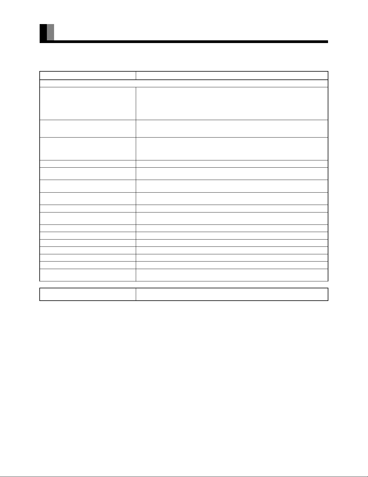
SPECIFICATION (Continued)
AV SELECTOR (FOR USE WITH THE PROJECTOR)
Model LPF-QSD1W
External equipment terminals
Video 1, 2, 4 input terminal
(Component video, S-video priority)
Video 3 input terminal
(S-video priority)
Video 5, 6 input terminal Component video: 3 Pin jack terminals Y: 1 Vp-p/75 :
Video 7 input terminal Video/audio: HDMI terminal (HDMI type A connector)
RGB 1 input terminal Video: DVI-D terminal (EIA/CEA-861B Compliant)
RGB 2 input terminal Video: mD-sub 3 parallel 15-pin 0.7 Vp-p/75 :
RGB 3 input terminal Video: mD-sub 3 parallel 15-pin 0.7 Vp-p/75 :
Digital 1, 2 audio input terminal Optical input
Amplifier output terminal Analog audio: Pin jack 0.5 Vrms (Left, Right)
RS232C 9 pin D-sub terminal (for servicing)
Terminal for display Display (PICTURE) output terminal
Weight 5 kg / 11.0 lbs
Outer dimensions 43.0 (W) x 9.5 (H) x 35.0 (D) cm / 16.9 (W) x 3.7 (H) x 13.8 (D) inch
Power supply 110-240 VAC 50/60 Hz
Current rating 0.45-0.24 A
Operating conditions Temperature: 5 to 35 °C / 32 to 104 °F
Video: Pin jack 1.0 Vp-p/75:
S-video: S-video terminal (Y-signal 1.0 Vp-p/75 : , C-signal 0.286 Vp-p/75 : )
Component video: 3 Pin jack terminals Y: 1 Vp-p/75 :
Audio: Pin jack 0.5 Vrms (Left, Right)
Video: Pin jack 1.0 Vp-p/75 :
S-video: S-video terminal (Y-signal 1.0 Vp-p/75 :, C-signal 0.286 Vp-p/75 : )
Audio (Same as RGB input 3):Pin jack 0.5 Vrms (Left, Right)
Audio: Pin jack 0.5 Vrms (Left, Right)
Audio: Mini pin jack 0.5 Vrms (Left, Right)
Audio: Mini pin jack 0.5 Vrms (Left, Right)
Audio (Same as video input 3):Pin jack 0.5 Vrms (Left, Right)
Digital audio: Optical cable audio terminal
Humidity: 20 to 80 %
P
: 0.7 Vp-p/75 :
B/CB
PR/CR: 0.7 Vp-p/75 :
: 0.7 Vp-p/75 :
P
B/CB
: 0.7 Vp-p/75 :
P
R/CR
Accessories 1 remote control, 2AAA batteries, 1 user’s manual, 2 power cable, 1 System cable
Regulation
• UL, CSA Safety: UL6500, C-UL
EMC: FCC Part 15, ICES-003
• CE Safety: EN60065
EMC: EN55013 2001
EN55020 1994
• AS Safety: IEC60065
EMC: AS/NZS 1053
Note
• Specifications and external appearance may be change for the sake of improvement.
(PICTURE), 3 ferrite cores, 4 air filters, 2 antivibration cushions
E-62
 Loading...