

Page 1
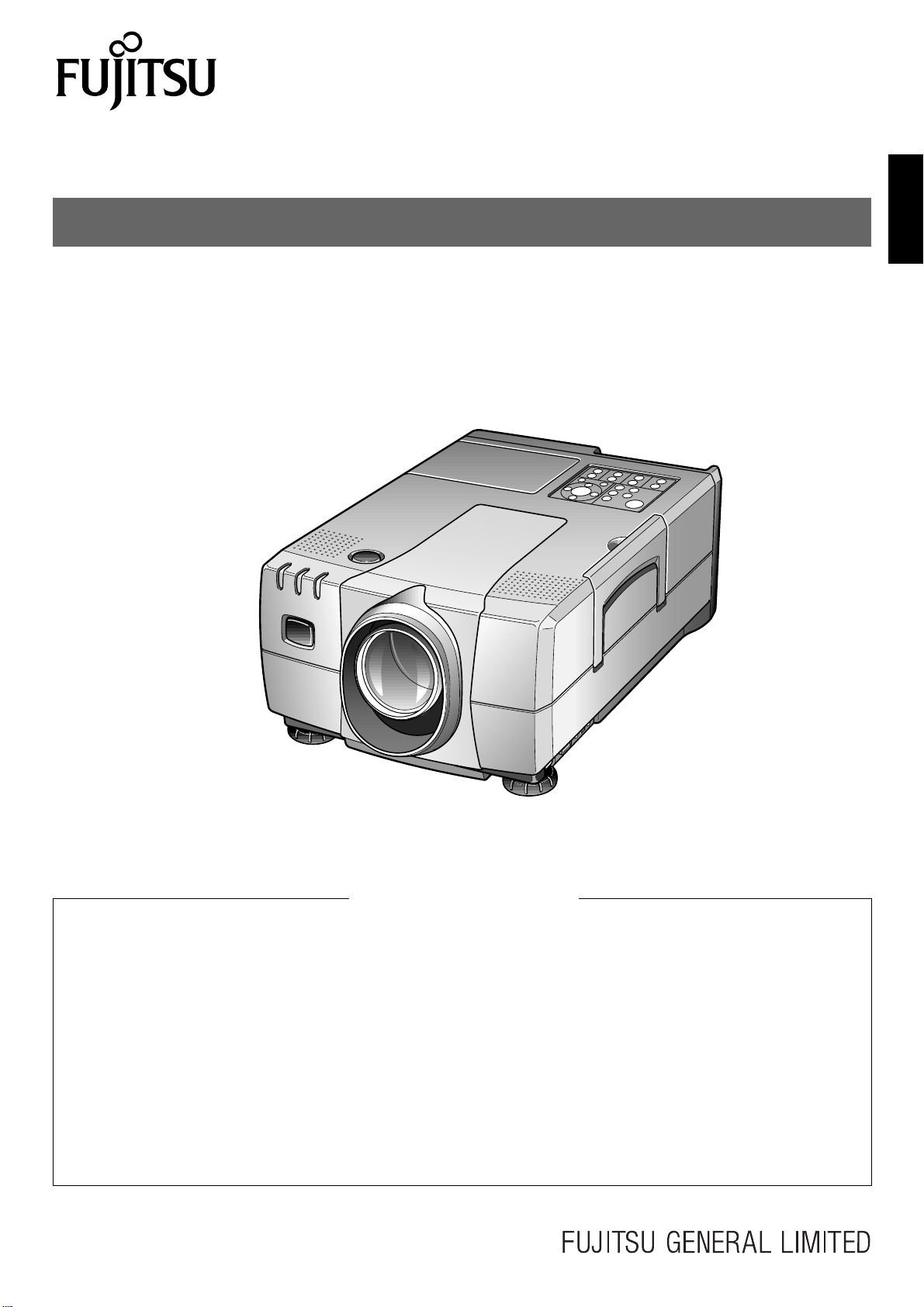
USER’S MANUAL
LCD PROJECTOR
LPF-7200/LPF-7200E
EnglishFrançaisDeutschEspañol
CONTENTS
Important Information .......................................... En-3
Important Safeguards ......................................... En-3
Features .............................................................. En-6
Checking the Accessories................................... En-7
Points to Note...................................................... En-8
Names of Parts ................................................. En-11
Handling the Wireless Remote
Control Unit .................................................... En-13
Setting Up ......................................................... En-15
External Connection
(To a PC)........................................................ En-17
(To a Video/Laser Disk/DVD).......................... En-19
Mouse Functions............................................... En-20
Connecting the Power Source........................... En-20
Basic Operation................................................. En-21
Operating the Menu Screens ............................ En-25
Adjusting the IMAGE......................................... En-27
Adjusting the POSITION ................................... En-29
Adjusting the SOUND ....................................... En-30
Setting the DISPLAY ......................................... En-30
Setting the INSTALLATION ............................... En-32
Maintenance and Care...................................... En-33
Changing the Lamp........................................... En-34
Troubleshooting................................................. En-36
Specifications .................................................... En-37
En-1
Page 2

DECLARATION OF CONFORMITY
We : Fujitsu General (Euro) GmbH
Werftstraße 20, D-40549 Düsseldorf, F.R. Germany
as the representative of
Manufacturer : Shinjyo Fujitsu General Limited
702-3 Kanazawa Shinjyo-shi Yamagata Japan
declares under our sole responsibility that the product
Product T ype : LCD Projector
Model Name : LPF-7200, LPF-7200E
to which this declaration relates is in conformity with the following standards :
European standards :
By conformance with the standards referenced the product follows the provisions of the directives listed below:
Place of Issue : Germany
Date of Issue : May. 2000
Declaration Reference : Fujitsu General (Euro) GmbH
EMC : a. EN 55022 1994, class A
b. EN 61000-3-2 1995
c. EN 61000-3-3 1995
d. EN 50082-1 1992
(IEC 801-2 1991/IEC 801-3 1984/IEC 801-4 1988)
Safety : a. EN 60950 1992/ A1: 1993 / A2: 1993 / A3: 1995 / A4: 1997
a. EC Council Directive 89/336/EEC of 3 May 1989
b. EC Council Directive 92/31/EEC of 28 April 1992
c. EC Council Directive 93/68/EEC of 22 July 1993
d. EC Council Directive 73/23/EEC of 19 February 1973
Signature :
H.Hirosaki, Managing Director
Fujitsu General (Euro) GmbH
Werftstraße 20, D-40549 Düsseldorf, F. R. Germany
Tel: 0211-50098-0 Fax: 0221-50098-50
This equipment has been tested and found to comply with the limits f or a Class A digital device , pursuant to P art 15
of the FCC Rules. These limits are designed to provide reasonable protection against harmful interference when
the equipment is operated in a commercial environment. This equipment generates, uses, and can radiate radio
frequency energy and, if not installed and used in accordance with the instruction manual, may cause harmful
interference to radio communications.
Operation of this equipment in a residential area is likely to cause harmful interference in which case the user will
be required to correct the interference at his own expense.
This Class A digital apparatus complies with Canadian ICES-003.
Cet appareil numérique de la classe A est conforme à la norme NMB-003 du Canada.
En-2
Page 3
Dear Customer:
W e ha ve prepared this USER’S MANUAL to assist you in the operation of your new LCD Projector . We thank you for your purchase
and hope you will be satisfied with the quality and performance of this projector.
Please read the instructions carefully, and keep them available for future reference.
Important Information
WARNING: THIS UNIT HAS AN EXTREMELY BRIGHT LIGHT SOURCE. DO NOT
STARE INTO THE BEAM OF LIGHT. BE ESPECIALLY CAREFUL THAT
CHILDREN DO NOT STARE DIRECTLY INTO THE LIGHT.
WARNING: TO REDUCE THE RISK OF FIRE AND ELECTRIC SHOCK, DO NOT
EXPOSE THIS PRODUCT TO RAIN OR MOISTURE.
The lightning flash with the arrowhead
CAUTION
RISK OF ELECTRIC SHOCK.
DO NOT REMO VE SCREWS
EXCEPT IF SPECIFIED USER
SERVICE SCREWS MARKED “ ”
CAUTION: TO REDUCE THE RISK OF ELECTRIC SHOCK,
DO NOT REMOVE COVER.
NO USER-SERVICEABLE PARTS EXCEPT LAMP UNIT.
REFER SERVICING TO QUALIFIED SERVICE
PERSONNEL.
symbol in a triangle, is intended to alert
the user to the presence of uninsulated
“dangerous voltage” within the product’s enclosure that may be of sufficient magnitude to constitute a risk of
electric shock to persons.
The exclamation point within a triangle is intended to alert the user to the
presence of important operating and
maintenance instructions in the literature accompanying the product.
EnglishFrançaisDeutschEspañol
Important Safeguards
This unit has been engineered and manufactured to assure your personal safety. But IMPROPER USE CAN RESULT IN POTENTIAL
ELECTRICAL SHOCK OR FIRE HAZARD.
In order not to defeat the safeguards incorporated into this LCD projector, observe the following basic rules for its installation, use and service.
Please read these “Important Safeguards” carefully before use.
–– All the safety and operating instructions should be read before the product is operated.
–– The safety and operating instructions should be retained for future reference.
–– All warnings on the product and in the operating instructions should be adhered to.
–– All operating instructions should be followed.
–– Do not place this product on an unstable cart, stand, or table. The product may fall, causing serious injury to a child or adult, and serious damage
to the product.
–– When the product is used on a cart, care should be taken to avoid quick stops, excessive
force, and uneven surfaces which may cause the product and cart to overturn, damaging
equipment or causing possible injury to the operator.
–– When connecting other products such as VCR’s and personal computers, you should turn off the power of this product for protection against
electric shock.
–– When using this projector, you should connect enclosed three-wire type power supply cord.
–– When there is an abnormal condition such as smoke or a strange smell in the machine, always pull out the plug from the wall outlet.
If a projected image does not appear or other abnormality occurs, make sure that no smoke comes out of the machine and contact your sales
office. This condition may cause fire or electrical shock.
En-3
Page 4

Important Safeguards (continued)
–– Do not insert metallic objects, flammable objects or water in the ventilation holes.
If a foreign object enters the unit, always pull out the electrical plug from the wall outlet and contact your sales off ice. This condition may cause
fire or electrical shock.
–– Do not place any heavy object on the electrical cord.
The cord will be damaged and this condition may cause fire or electrical shock.
–– Do not loosen any screws that are not indicated by the
The unit contains internal parts which have high volta ge or high temperatures. Touching these parts may cause electrical shock or severe bur ns.
–– Do not touch the electrical plug when there is thunder or lightning.
Touching the projector in this condition may cause electrical shock.
–– Do not place the electrical cord near a heater or other object that generates high temperatures.
Place the electrical cord so it does not touch a heater. This may cause fire or electrical shock.
–– Do not place the projector in an unstable location.
If the projector is placed on a shaky frame or unstable location it may fall and cause injury.
–– Only use the accessory electrical cord.
Fire or electrical shock may occur if a nonstandard cord is used.
–– Contact your sales office when transporting the projector.
If you install or transport the unit by yourself, it may fall and cause a fire, electrical shock or other damage.
–– Clean the electrical plug periodically to prevent dust from accumulating.
Fire or electrical shock may occur if the insulation on the electrical plug becomes defective.
–– If the lamp storage cover is broken when replacing the lamp, do not use the projector and contact your sales office for repair.
–– Always place the projector a minimum of 30cm (12 inches) away from a wall.
Place the projector in a well ventilated area because it generates high temperatures. Never place the projector under a carpet or b lanket because
this may cause a fire.
–– The electrical plug of the main unit is equipped with a three line plug that contains a ground line. Contact an electrical technician to connect the
ground line when connecting it to a wall outlet with a two core plug.
–– Insert the electrical plug securely to the end of the wall outlet.
If the plug is inserted incorrectly, this may cause fire or electrical shock.
arrow mark.
–– Do not place vases, cups or other object containing water or fluids on top of the projector.
Do not use the projector in rain, wind or other inclement weather. Fire or electrical shock may occur if rain or other objects enter the unit.
–– Do not insert metallic objects, or flammable objects such as plastic or paper into the lamp unit or lamp storage unit.
Contact your sales office if a foreign object enters the unit. This may cause fire or electrical shock.
–– When the lamp unit is used, do not drop any object on the unit or subject parts such as the glass surface, connector , connector terminal, cables and
case to impact.
Do not use the unit if it is subjected to shock or scratched. Contact your sales office. This condition may cause a fire or electrical shock.
–– Never cover the ventilation holes.
Do not seal or shut off the ventilation holes on the bottom surface. Do not place the unit on top of a carpet or cushion.
–– Do not touch the terminal end of the lamp unit or the screws which secure the connector.
Even if the screws become loose, do not attempt to perform the repair operation yourself and contact your sales of fice. T his condition may result
in fire, electrical shock or other damage.
–– Do not turn on the electricity or the lamp when the lens cap is attached.
The lens cap will become deformed due to the heat of the lamp and may cause fire or severe burns.
–– Do not clean the lens directly.
Looking at the lens during operation is dangerous because it projects a strong light during operation. This may cause severe damag e to your eyes.
–– Always pull out the electrical plug when the unit is not used for a long period of time.
If the plug is not removed, the insulation may deteriorate and cause electrical shock or a fire due to current leakage.
–– Always grasp the plug firmly and never pull on the electrical cord to remove the electrical plug from the wall outlet.
If the cord is pulled, it may be damaged and cause fire or electrical shock.
–– Always turn off the power before connecting the cables and other connections.
Read the instruction manuals of the other equipment connected to the projector thoroughly. Always turn off the main power switch before
connecting any cables. Fire or electrical shock may occur when these operations are performed if the main power is turned on.
–– Do not apply any force on the projector.
If the projector is suspended or a load is applied to it from a heavy object upon it, the projector may fall and be damaged.
En-4
Page 5
–– Be careful not to expose the projector to any steam, oily smoke, heat or humidity.
Never place the projector in a location subject to steam, oily smoke heat or humidity. This may cause fire or electrical shock.
–– Never place flammable objects such as a cigarette lighter, matches, gas canisters, spray cans, fireworks or plastic materials close to the lamp
ventilation holes. This may cause fire or other damage.
–– Always turn off the power switch before replacing the lamp. Allow the unit to cool off for at least one hour before replacing the lamp.
Replace the lamp according to the directions in the operation manual. Fire, burns or electrical shock may occur if the replacement is performed
incorrectly.
–– A laser beam is projected if the laser button in the accessory wireless remote control is pressed. Never look directly into the laser beam.
The laser beam may cause damage if it enters the eyes directly.
–– As there is the possibility that ozone (O
3
) will be generated by the lamp power supply, handle the projector correctly according to the warnings
listed in this operation manual.
–– Be careful to avoid condensation.
Dew or moisture condensation may be produced inside the projector if there are temperature differences between the inside and outside of the
unit. Make sure that the projector has warmed up to room temperature before using it. This condition may cause electrical leakage, shock or f ire.
–– Be careful when transporting the projector.
When transporting the projector, always remo ve the electrical plug and other cables. Be e xtremely careful to av oid dropping it or subjecting it to
any shock or impact as this may cause fire or electrical shock.
–– Never touch the electrical plug with wet hands.
This may cause electrical shock.
–– Do not touch the lamp storage cover interlock mechanism.
Fire, electrical shock or other damage may occur if the interlock mechanism does not operate correctly.
–– This product should be operated only with the type of power source indicated on the label. If you are not sure of the type of power supply to your
home, consult your product dealer of local power company.
EnglishFrançaisDeutschEspañol
–– Use a plug with a ground terminal. This plug will fit only into a grounded power outlet. If you are unable to insert the plug into the outlet, contact
your electrician to install the proper outlet. Do not defeat the safety purpose of the grounded plug.
–– Use only the accessory cable designed for this product to prevent shock.
The power supply voltage rating of this product is AC 100 – 240 V, the power cable attached conforms to the following power supply voltage.
Use only the power cable designated by our dealer to ensure Safety and EMC.
When it is used by other power supply voltage, power cable must be changed.
Power cable
The included cable differs according to the model.
Power supply voltage: AC100 –125V AC200 –240V AC240V
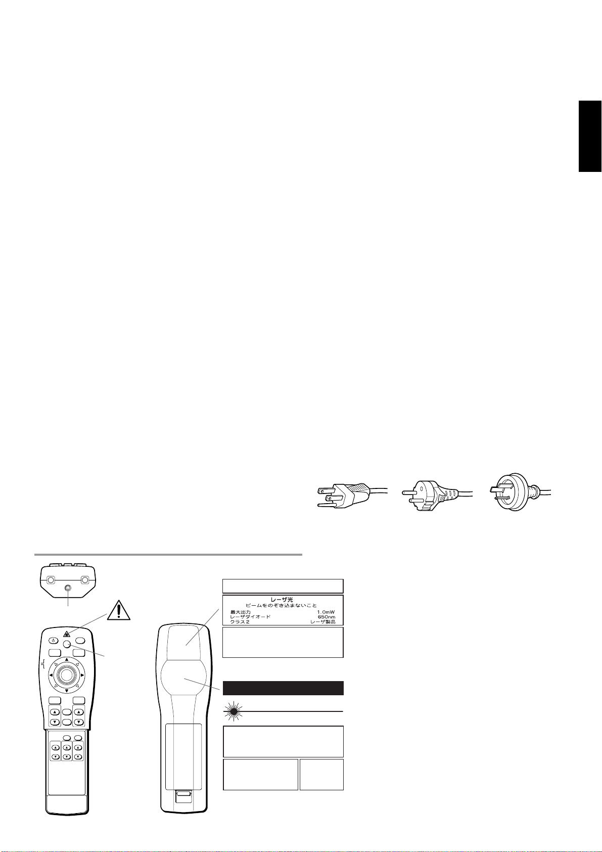
Using the Remote Control Laser Pointer
• When the LASER button on the remote control is
pressed, a laser beam is emitted from the laser
window shown in the figure.
• Do not look directly at the laser beam and do not
point the beam at another person.
• Take care not to get the wireless remote control
unit wet. Failure may result.
• Do not disassemble the wireless remote control
unit. Injury or failure may result.
• Do not modify the wireless remote control unit.
Injury or failure may result.
CAUTION
Use of controls or adjustments or performance of
procedures other than those specified herein may
result in hazardous radiation exposure.
Laser window
POWER
MUTE
LASER
RGB
VIDEO
MOUSE
PJ
MENU
ENTER/R-MOUSE
ZOOM-PAN
VOLUMESOURCE
CANCEL
STATUS
AUTO
ZOOM
KEYSTONE
FOCUS
Caution label
LASER
button
AVOID EXPOSURE
RADIATION IS EMITTED FROM THIS APERTURE
RAYONNEMENT LASER
NE PAS REGARDER DANS LE FAISCEAU
APPAREIL A LASER DE CLASSE2
EN60825-1 : 1994 + A11
LONGUEUR D'ONDE : 650nm
PUISSANCE MAXIMA : 1mW
-
LASER
CAUTION
VISIBLE LASER RADIATION
DO NOT STARE INTO BEAM
WAVE LENGTH : 650nm MAX OUTPUT : 1mW
CLASS II LASER PRODUCT
LASER RADIATION
DO NOT STARE INTO BEAM
CLASS 2 LASER PRODUCT
EN60825 - 1 : 1994 + A11
WAVE LENGTH : 650nm MAX OUTPUT : 1mW
LASER-STRAHLUNG
NIGHT IN DEN STRAHL
BLICKEN LASER KLASS 2
EN60825-1 : 1994+A11
WELLENLÄNGE : 650nm
MAX AUSGANGSLEISTUNG : 1mW
Complies with 21 CFR 1040.10 and 1040.11
REMOTE CONTROL MODEL LPF-720RC
May-2000
Place of
Manufacturer : A
Made in Japan
En-5
Page 6

Features
The LPF-7200/7200E projector enlarges PC or video images and projects them onto a 30 – 300-inch screen (available
on the market).
■ High luminance and high resolution
• High luminance enables use of the projector even in a bright room.
• A wide range of resolutions from VGA to SXGA can be met.
■ Functional design
• Compact size and weighing only 7.5kg, the projector is light to carry and easy to set up.
■ High image quality by digital image processing
• The projector is compatible with most video formats (NTSC, NTSC4.43, PAL, PAL-M, PAL-N, PAL-60,
SECAM).
• It produces high quality, clear video images by 3-dimensional Y/C separation circuit (on NTSC video format).
• The DVI (digital video interface) input terminal and BNC terminal enable connection to a wide range of image
equipment.
■ Easy-to-operate wireless mouse remote control unit
• The remote control unit can be used as a PC mouse while viewing images on the screen.
• The built-in laser pointer is useful for presentations.
• Direct key operation enables easy zoom adjustment, focus adjustment and keystone correction.
• Remote control is possible by connecting the wired cable (optional).
■ Simple vertical movement of image
• The screen image can be moved up and down easily using the lens shift function without distorting the trapezoid.
■ Simple correction of image trapezoid distortion
• Distortion of the trapezoid caused by the angle of incidence with the screen can be corrected easily using the
keystone correction function.
■ Clear, easy-to-use OSD (on-screen display)
• The input signal status, life of the lamp and present adjustment status can be checked all at once using the status
display function.
En-6
Page 7
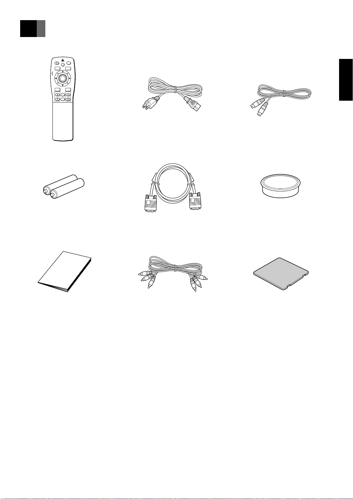
Checking the Accessories
Wireless remote control unit x 1
POWER
MUTE
LASER
VIDEO
RGB
MOUSE
PJ
MENU
ENTER/R-MOUSE
ZOOM-PAN
VOLUMESOURCE
CANCEL
Size AA batteries x 2
Power cable x 1
RGB cable x 1
PS/2 mouse connection cable x 1
EnglishFrançaisDeutschEspañol
Lens cap (to protect the lens) x 1
Instruction manual x 1
(this manual)
AV cable x 1
Air filter x 1
En-7
Page 8
Points to Note
Transporting the projector
Put the projector in the box in which it was purchased when transporting it. Excessive pressure on the lens may result in damage.
About the lamp
• The lamp is an expendable item. It should be changed when
the “Approaching Recommended Lamp Life!” message is
displayed or when the lamp is nearing the end of its service
life as indicated by failure, a dark image and poor colors.
Replace with a new lamp (available at the store where the
projector was purchased).
• Change the lamp when the warning message shown on the
right is displayed.
• The lamp will fail to light about 100 hours after the message is
displayed.
For instructions on how to change the lamp, see page 34.
Approaching Recommended Lamp Life!
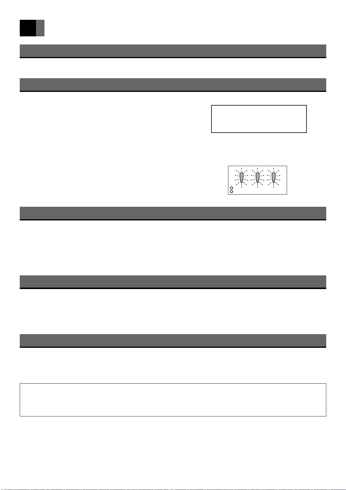
The lamp will fail to light and the POWER-ON, TEMP
and LAMP monitors will flash about 100 hours after
this message is displayed.
(Warning message)
WARNING
▼
STAND-BY
POWER-ON
(Power) (Temperature) (Lamp)
TEMP LAMP
Precautions when connecting to a PC
• When connecting the projector to a notebook PC
When connecting the projector to a notebook PC, enable the RGB external image output on the PC (simultaneous display on the
LCD and CRT or set on the CRT). For details, see the instruction manual supplied with the PC.
• Setting the PC display
When selecting the type of display on Windows 95/98, etc. or when setting is required, select [Super VGA 800 x 600], [Super
VGA 1024 x 768], [Super VGA 1280 x 1024] or [Standard VGA 640 x 480] on the standard monitor.
Power sequence
• Precautions when turning on power
If the projector is connected to a PC, to avoid trouble, turn the projector on before turning the PC on. (This is particularly
important if the mouse connected is not a USB mouse or if using a Macintosh PC.)
• Precautions when turning off power
If the projector is connected to a PC, to avoid trouble, turn the PC off before turning the projector off.
Earth connection
• The power plug is a 3-pin plug with earth wire. If using a 2-pin socket, be sure to earth the projector.
• Have an electrician perform the earthing.
• Earth the projector before plugging in to the power source. Before removing the earth connection, be sure to remove the plug
from the power source.
• This projector is a Class A information technology device based on Voluntary Control Council for Interference by Informa-
tion Technology Equipment (VCCI) standards. If used in a home environment, it may cause interference and the user may
be required to take appropriate measures.
• This projector conforms to high frequency guidelines.
En-8
Page 9
Monitor Display
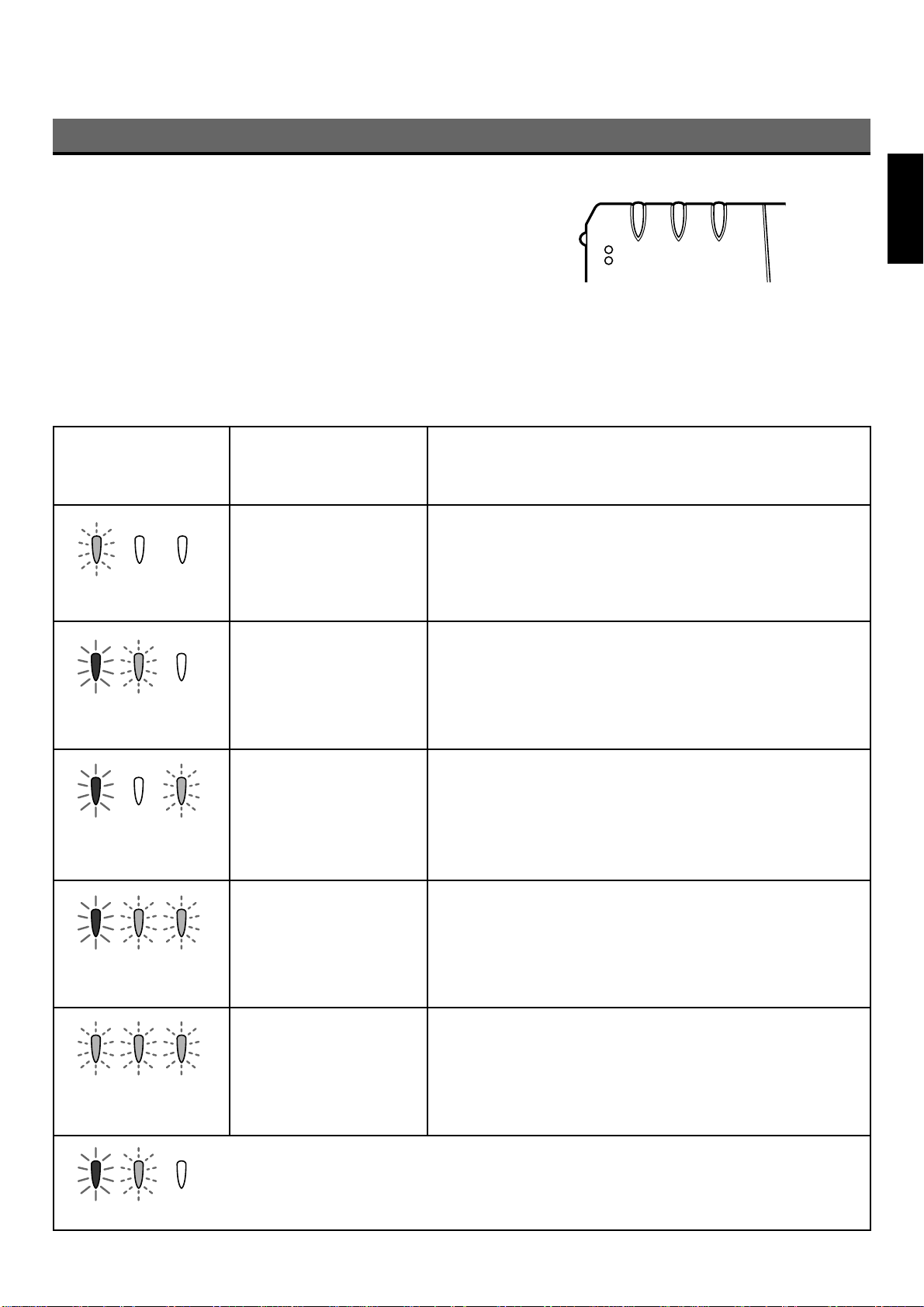
• Normal or abnormal operation of the internal parts is indicated by the 3
monitors on the front of the projector. (See illustration on right)
(Monitor Display)
• When the power cable is plugged into the socket, the POWER-ON
monitor lights red and the projector is in standby status.
• When the POWER button is pressed in standby status, the POWER-ON
monitor lights green and the lamp comes on.
• When the POWER button is pressed while the lamp is on, the POWER-
STAND-BY TEMP LAMP
POWER-ON
(Power) (Temperature) (Lamp)
ON monitor lights orange and the lamp cools for about 2 minutes. The
POWER-ON monitor then changes to red and the projector returns to
standby status.
• In the event of an abnormality, depending on the fault, the POWER-ON, TEMP and LAMP monitors light or flash red as shown
below and the power is automatically turned off. Follow the instructions below to remedy the fault.
Monitor Display
STAND-BY TEMP LAMP
POWER-ON
(Power) (Temperature) (Lamp)
Filter holder is out of
Condition
Remedy
Check the filter holder. (See page 33)
place.
POWER-ON monitor is
flashing.
EnglishFrançaisDeutschEspañol
POWER-ON monitor is on
and TEMP monitor is
flashing.
POWER-ON monitor is on
and LAMP monitor is
flashing.
POWER-ON monitor is on
and TEMP and LAMP
monitors flash alternately.
POWER-ON, TEMP and
LAMP monitors are all
flashing.
Internal temperature is
abnormally high.
Lamp fails to light.
Fan failure
End of service life of
lamp.
If ventilation opening is blocked, remove blockage and allow
projector to cool.
Check air filter and if it is blocked with dirt, clean or replace.
(See page 33)
If condition persists, take to store where purchased for
repairs.
Wait 1 minute and start up again. At this time, fan rotates for
about 1 minute to cool internal parts. If condition persists, take
to store where purchased for repairs.
If rotation of the cooling fan is obstructed, remove obstruction.
Unplug power cable from socket to cancel display.
If condition persists, take to store where purchased for
repairs.
Contact store where purchased and replace with a new lamp.
See page 34 for instructions on how to change the lamp.
On Flashing Off
As shown left, the monitors light or flash red, or are off.
En-9
Page 10
Points to Note (continued)
Illumination around projector
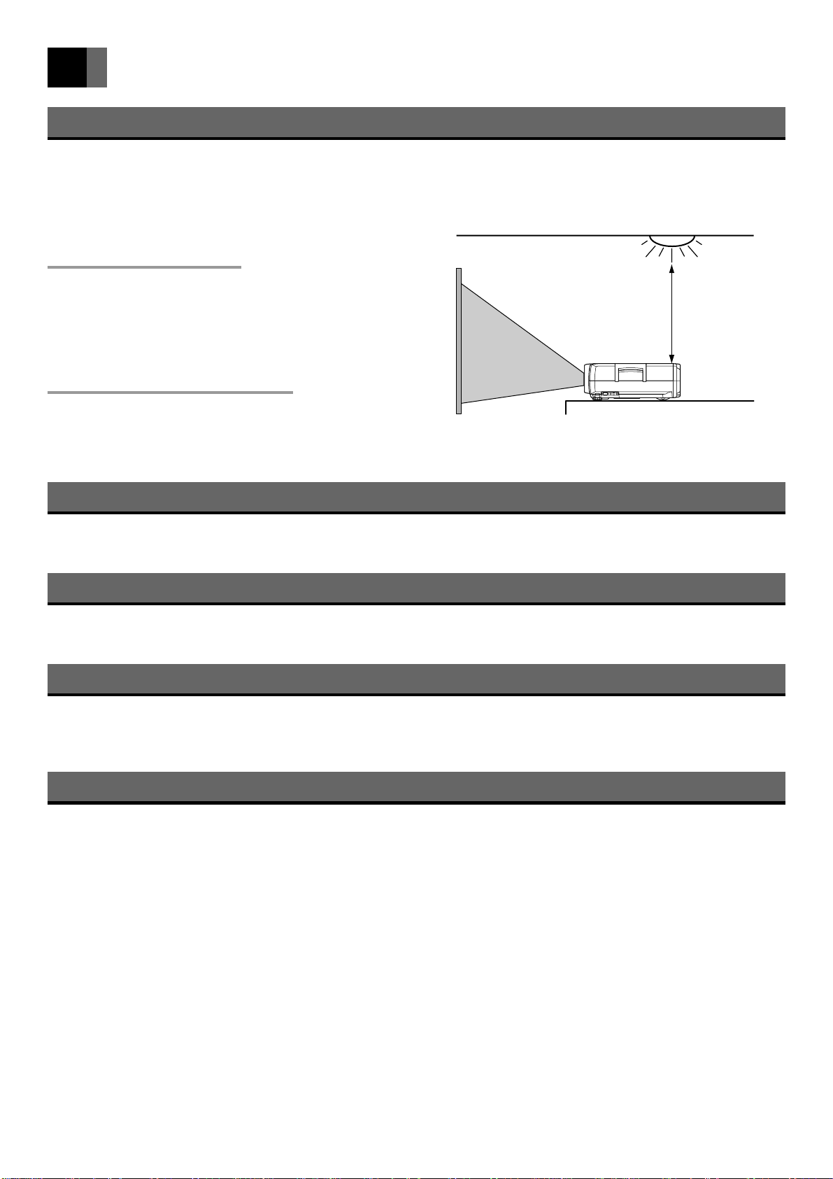
The projector has two wireless remote control unit light receivers, on the front and rear. If the receivers are subjected to strong
light such as from fluorescent lights, the remote control unit may not function properly. In this case, move the projector away from
the fluorescent light or other light source, or position it so that light from the light source does not shine directly on the receivers.
Moving the projector away
Light source
from the light source
Move the projector at least 2m from the fluorescent light or other
light source. Keep the wireless remote control unit light receivers
out of direct sunlight.
Over 2m
To disable the wireless remote
control unit light receivers
Change the remote control input setting using the function
settings.
For details, see page 32.
Image characteristics
The projector is equipped with a liquid crystal panel. The colors and contrast of the projected image may differ from the CRT
image on a TV or PC.
Screen
Do not use a polarizing screen with this projector as the image may appear reddish. If you are choosing a screen, check the
characteristics carefully first and choose one that suits your purpose.
Output terminal
Of the signals sent to INPUT 1 terminal [RGB (analog) only], INPUT 2 terminal [RGB (analog)] and INPUT 3 terminal (RGB
output in the case of component video input), the projected signals are output by the RGB output terminal.
Signals input to INPUT 4 terminal (S-VIDEO/VIDEO) and INPUT 1 terminal (DIGITAL RGB) are not output.
Using a mobile phone near the projector
If you use a mobile phone, transceiver or other device that generates radiowaves near the projector, it may cause distortion of the
image or noise from the speaker. Use such devices at a distance from the projector.
En-10
Page 11
Names of Parts
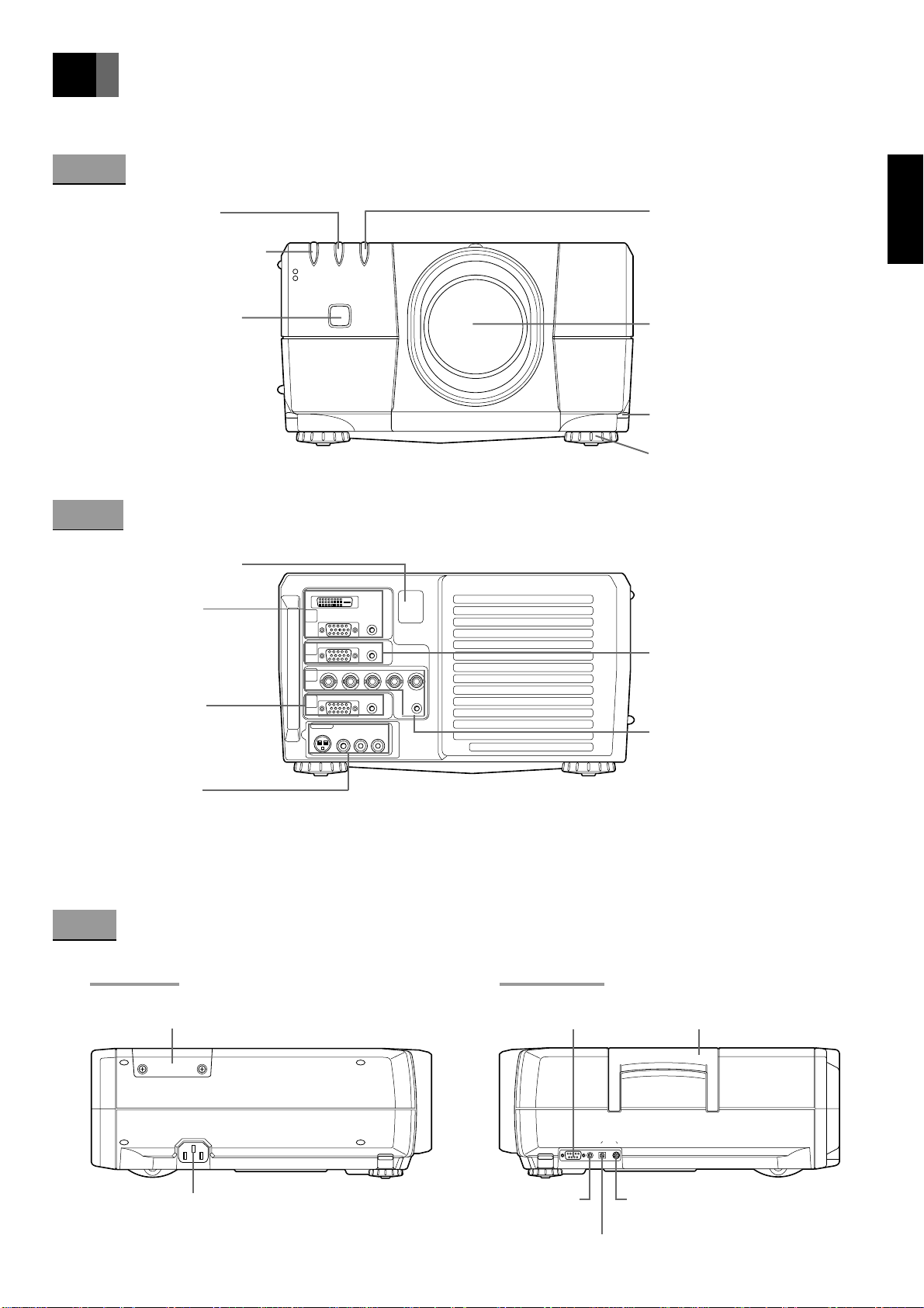
The figures in brackets refer to the relevant page number.
Front
Temperature monitor
(TEMP) [8, 9]
Power monitor (STAND-BY/
POWER-ON) [8, 9, 21]
Wireless remote control
unit light receiver [10, 13]
Back
Wireless remote control
unit light receiver [10, 13]
INPUT 1 terminal
DIGITAL RGB terminal
RGB terminal (analog)
AUDIO terminal
[17, 18]
OUTPUT terminal
RGB terminal (analog)
AUDIO terminal
[10, 17, 18]
INPUT 4 terminal
S-VIDEO terminal
VIDEO terminal
AUDIO L/R terminals
[19]
STAND-BY TEMP LAMP
POWER-ON
DIGITAL RGB
IN
PUT 1
RGB AUDIO
RGB
IN
PUT 2
Cr PrG YB Cb Pb
R
IN
PUT 3
OUT
PUT
INPUT 4
S-VIDEO
VIDEO
LR
AUDIO
AUDIO
AUDIO
HV
AUDIORGB
Lamp monitor (LAMP) [8, 9]
EnglishFrançaisDeutschEspañol
Projection lens [15]
Adjustment lever [15]
Adjuster [15]
INPUT 2 terminal
RGB terminal (analog)
AUDIO terminal
[17, 18]
INPUT 3 terminal
RGB terminal (analog)
Component terminals
AUDIO terminal
[17, 18, 19]
Side
Left side Right side
RS232C control terminal
Lamp cover [34 – 35]
AC 100V input terminal [20, 34]
(for service personnel)
WIRED REMOTE
terminal [14]
MOUSE USB terminal [20]
PS-232C
Handle
MOUSE
WIRED
REMOTE
USB PS/2
MOUSE PS/2 terminal [20]
En-11
Page 12
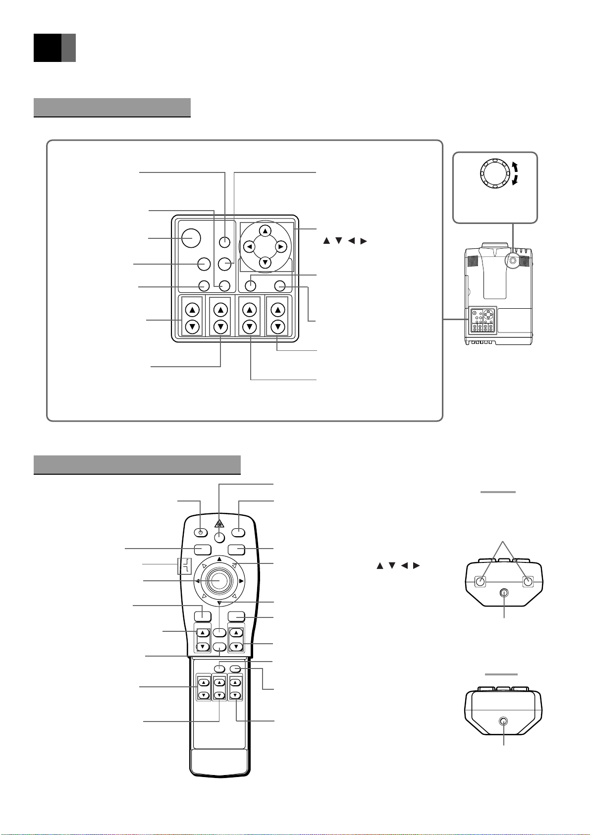
Names of Parts (continued)
The figures in brackets refer to the relevant page number.
Operation Panel (Top)
MUTE button
[23]
STATUS button
[24]
POWER button
[8, 9, 21, 34]
RGB button
[22]
AUTO button
[24]
POWER
FOCUSZOOM
MUTE
VIDEORGB
STATUSAUTO
KEY STONE
VOLUME
DOWN
VIDEO button
[22]
PUSH
UP
Lens shift
knob [16]
Adjustment buttons
( , , , ) [25 – 32]
ENTERMENU
MENU button [25]
ZOOM buttons
[22]
FOCUS buttons
[22]
Wireless Remote Control Unit
POWER button [8, 9, 21, 34]
POWER
LASER
RGB button [22]
Slide switch [20, 25]
L-MOUSE (left click)
button [20]
MENU button [25]
ZOOM-PAN buttons [23]
CANCEL button [23]
ZOOM buttons [22]
RGB
MOUSE
PJ
MENU
ZOOM-PAN
ZOOM
ENTER/R-MOUSE
CANCEL
AUTO
FOCUS
MUTE
VIDEO
VOLUMESOURCE
STATUS
KEYSTONE
ENTER button
[25 – 30]
VOLUME buttons
[23]
KEYSTONE buttons
[24]
LASER button [14]
MUTE button [23]
VIDEO button [22]
Adjustment buttons ( , , , )/
Mouse pointer buttons [20, 25 – 32]
SOURCE button [24]
ENTER/R-MOUSE (right
click) button [20, 25 – 29]
VOLUME buttons [23]
AUTO button [24]
STATUS button [24]
Front
Wireless remote
control unit infrared
light emitting window
[13]
Laser beam emitting
window [14]
Back
FOCUS buttons [22]
En-12
KEYSTONE buttons [24]
WIRED REMOTE
terminal [14]
Page 13
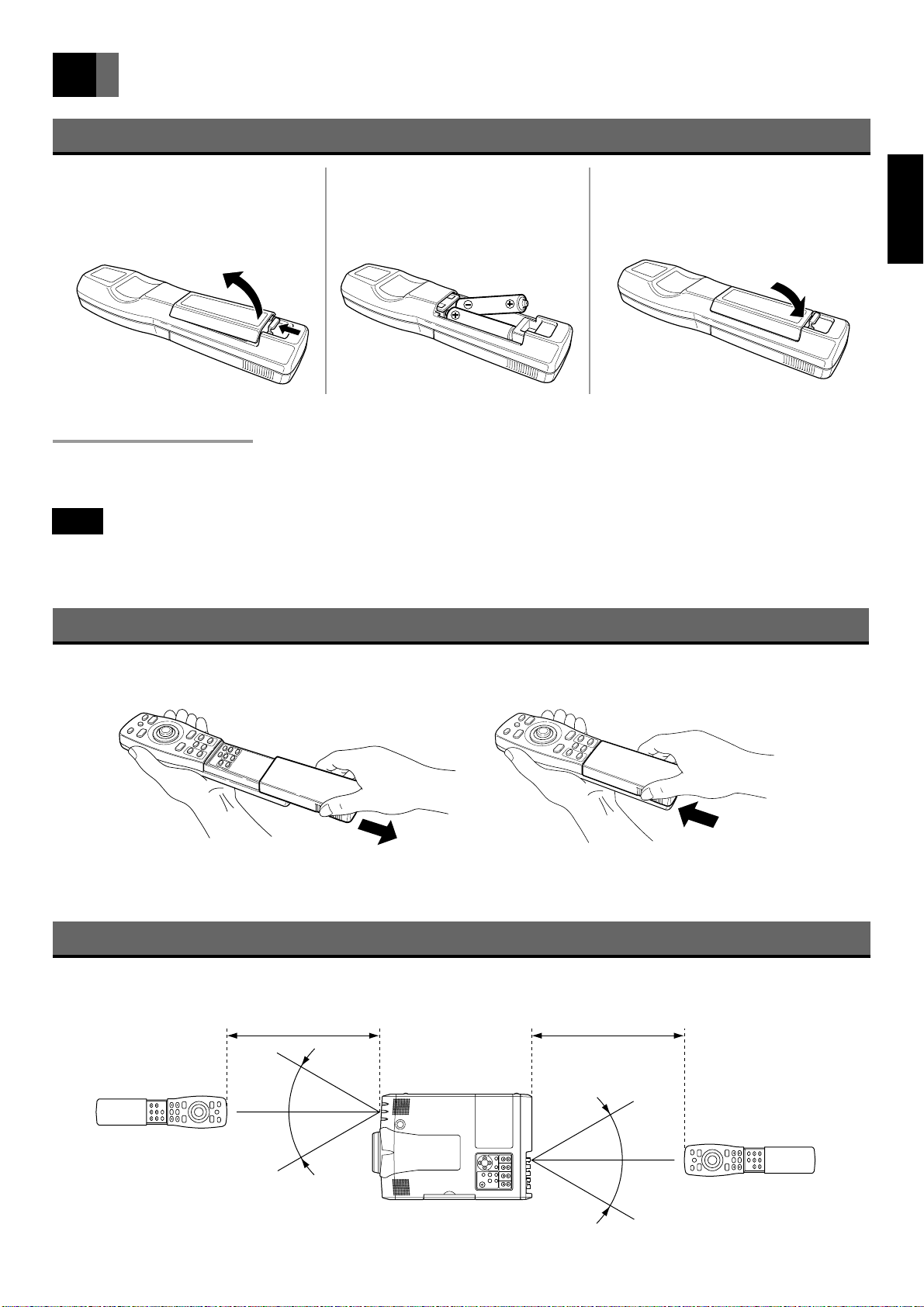
Handling the Wireless Remote Control Unit
Loading the Batteries (2 size AA batteries)
Open the battery cover on the back
1
of wireless remote control unit in the
direction shown.
Insert two size AA batteries,
2
making sure that the positive and
negative terminals are correctly
oriented.
Close the battery cover in the
3
direction shown.
About the Batteries
• Remove the batteries if the wireless remote control unit is not used for an extended period of time.
• When changing the batteries, use alkaline batteries. Use two new batteries of the same type. (The batteries supplied are for
checking functions.)
Note
• If the wireless remote control unit is placed face down, the MOUSE button will be pressed and the projector put in operation
status, resulting in exhaustion of the batteries. Be sure to store the remote control unit face up.
EnglishFrançaisDeutschEspañol
Opening and Closing the Wireless Remote Control Unit
Open and close the cover of the wireless remote control unit as shown below.
Open Close
Range of Use of the Wireless Remote Control Unit
Within 10m Within 10m
30°
30°
30°
30°
En-13
Page 14
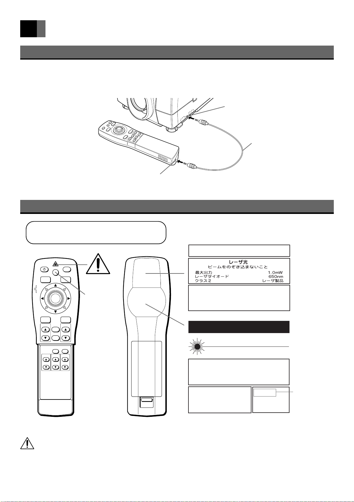
Handling the Wireless Remote Control Unit (continued)
Wired Connection
When the wireless remote control unit is used at a distance from the projector or there is an obstacle between them, the infrared
signal from the remote control unit may not reach the projector. In this case, connect the wireless remote control unit to the
projector using the wired cable (optional).
WIRED REMOTE terminal
Wired cable (optional: approx. 20m)
WIRED REMOTE terminal
Wireless Remote Control Unit Laser Warning Label
This wireless remote control unit is a Class 2 laser
product (max. output: 1mW; wave length: 650nm)
POWER
RGB
MOUSE
PJ
MENU
ZOOM-PAN
ZOOM
LASER
VIDEO
ENTER/R-MOUSE
VOLUMESOURCE
CANCEL
STATUS
AUTO
KEYSTONE
FOCUS
MUTE
Caution label
LASER button
AVOID EXPOSURE
RADIATION IS EMITTED FROM THIS APERTURE
RAYONNEMENT LASER
NE PAS REGARDER DANS LE FAISCEAU
APPAREIL A LASER DE CLASSE2
EN60825-1 : 1994 + A11
LONGUEUR D'ONDE : 650nm
PUISSANCE MAXIMA : 1mW
VISIBLE LASER RADIATION
DO NOT STARE INTO BEAM
WAVE LENGTH : 650nm MAX OUTPUT : 1mW
CLASS II LASER PRODUCT
LASER RADIATION
DO NOT STARE INTO BEAM
CLASS 2 LASER PRODUCT
EN60825 - 1 : 1994 + A11
WAVE LENGTH : 650nm MAX OUTPUT : 1mW
-
LASER
CAUTION
LASER-STRAHLUNG
NIGHT IN DEN STRAHL
BLICKEN LASER KLASS 2
EN60825-1 : 1994+A11
WELLENLÄNGE : 650nm
MAX AUSGANGSLEISTUNG : 1mW
May-2000
Place of
Manufacturer : A
Made in Japan
Year and Month
of manufacture
Complies with 21 CFR 1040.10 and 1040.11
REMOTE CONTROL MODEL LPF-720RC
Warning
• The wireless remote control unit supplied with the projector emits a laser beam when the LASER button is pressed. Do not
stare directly into the beam or point the beam at anyone as this may result in loss of eyesight.
• Do not disassemble or modify the wireless remote control unit supplied with the projector as this may result in injury or failure.
En-14
Page 15
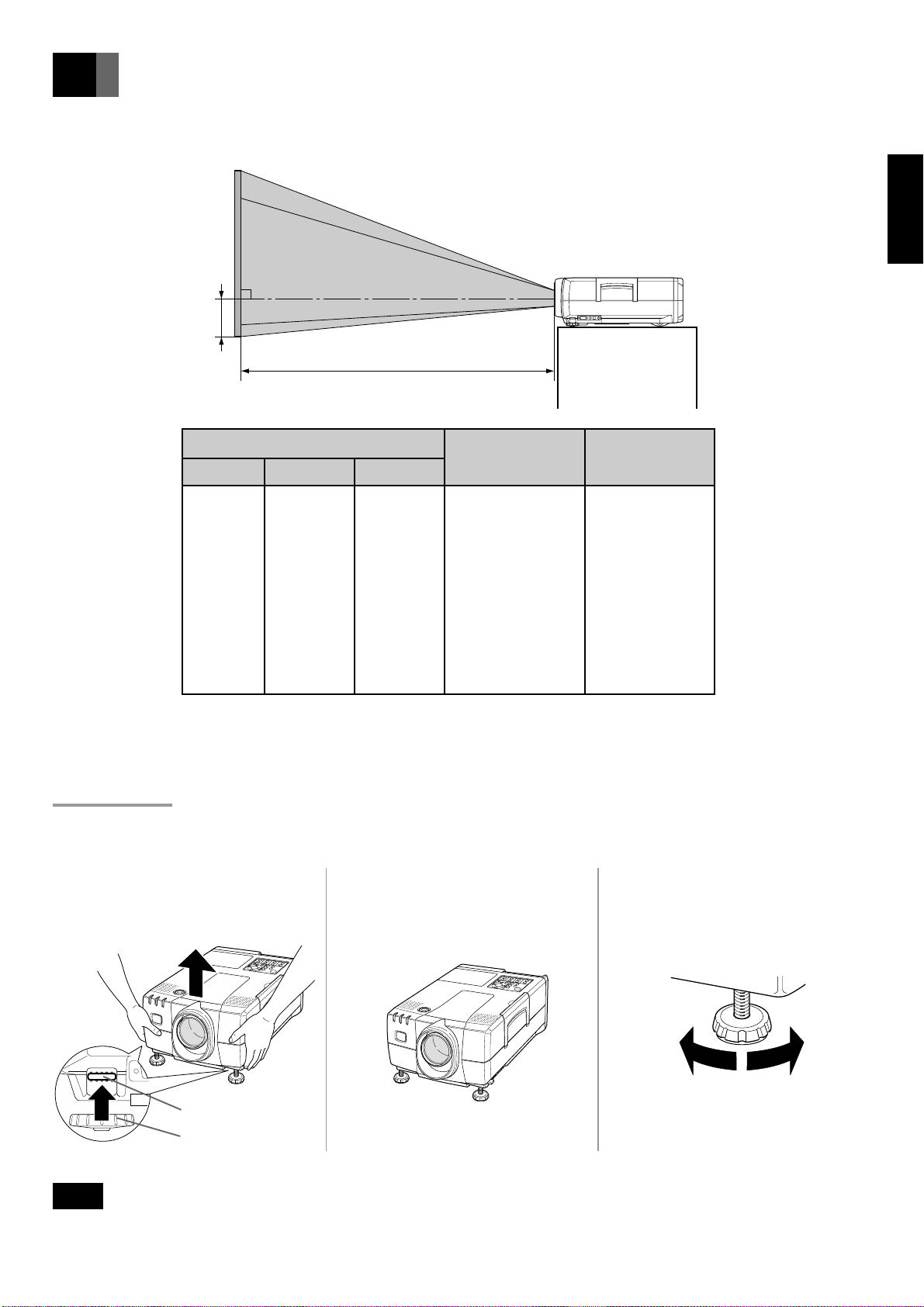
Setting Up
• There are 2 ways of setting the projector up: for regular projection and rear projection.
• By adjusting the zoom lens, you can choose the screen size as shown below.
Offset (O)
Projection distance (L)
EnglishFrançaisDeutschEspañol
Screen Size
Screen Size Height (cm)
20 30 41 0.7 – 0.9 2 – 29
40 61 81 1.4 – 1.9 3 – 58
60 91 122 2.1 – 2.8 5 – 87
80 122 163 2.9 – 3.8 6 – 116
100 152 203 3.6 – 4.7 8 – 145
150 229 305 5.4 – 7.1 11 – 217
200 305 406 7.3 – 9.4 15 – 290
250 381 508 9.1 – 11.8 19 – 362
300 457 610 10.9 – 14.1 23 – 434
* Offset is the distance from the middle of the projection lens to the bottom edge of the screen.
Width (cm)
Projection
distance L (m)
Offset O (cm)
Adjustment
• Adjust the height of the projector using the 2 adjusters on the front.
• If the relation between the position of the projector and the screen is not correct, the image will be distorted and blurred.
Lift the front of the projector while
1
pressing the two adjustment levers on
the side of the projector.
When the desired angle is reached,
2
release the adjustment levers to fix
the adjusters in that position.
Turn the adjusters for f ine adjustment.
3
Up Down
Adjustment lever
Adjuster
Note
• If you wish to lower the projector to its original position before storing it, press the adjustment levers and slowly lower the
projector. It can then be stored easily.
En-15
Page 16
Setting Up (continued)
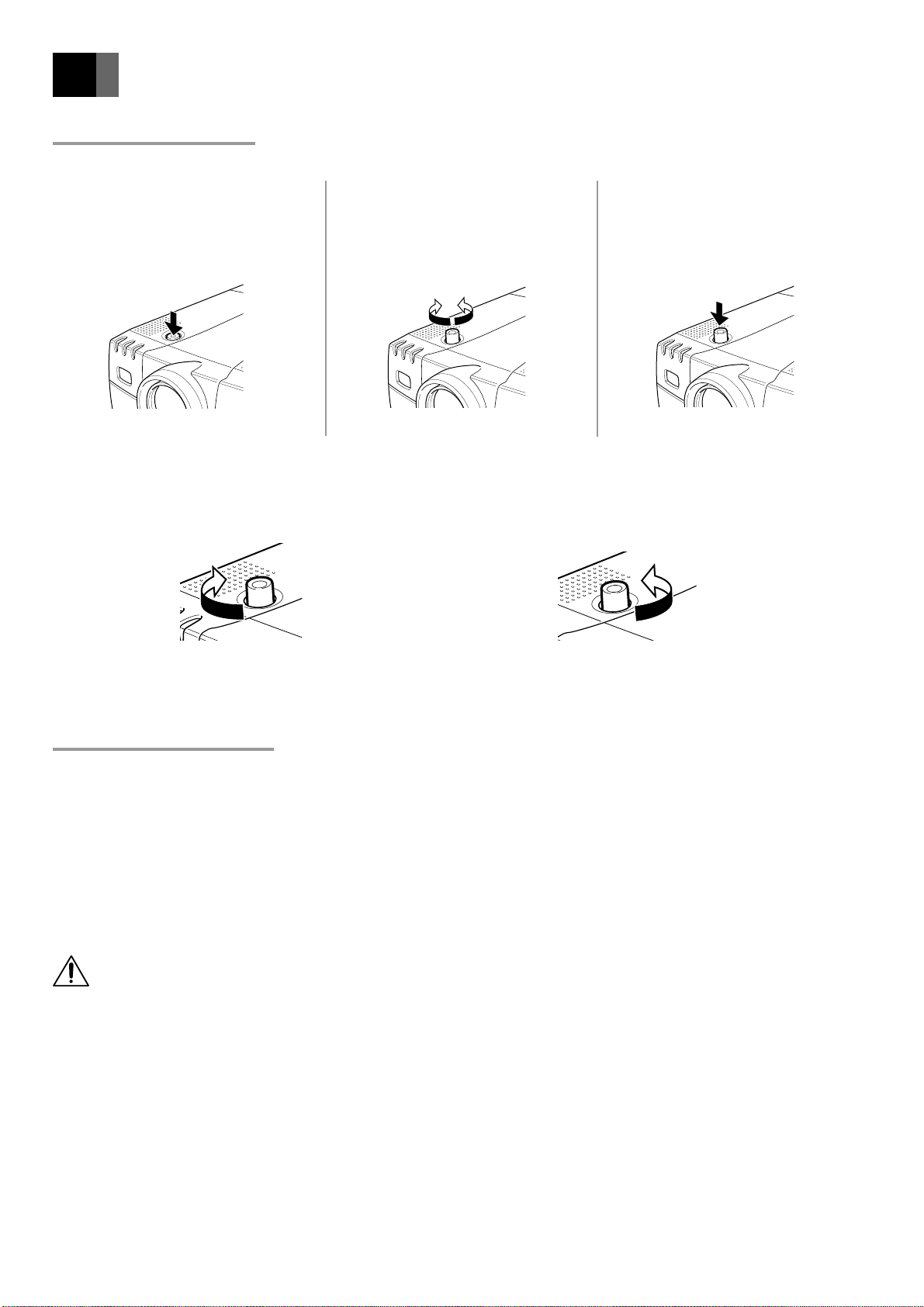
Lens Shift Function
By shifting the lens, the position of the image on the screen can be moved up and down.
Press the lens shift knob to extract
1
the knob so that it protrudes from the
projector.
To move the image up
Turn the lens shift knob clockwise.
Up
Turn the lens shift knob to adjust the
2
position of the image.
To move the image down
Turn the lens shift knob anticlockwise.
After adjustment, press the lens shift
3
knob to withdraw it to its original
position.
Down
Overhead Installation
• When fitting the projector to the ceiling, a ceiling attachment (optional) and ceiling unit flange pipe set (available on the market)
are necessary .
• The ceiling unit flange pipe set (pipe length) required differs according to the installation height. Consult the store where
purchased.
• Consult the store where purchased regarding installation work. A charge will be made for this work.
Warning
• Place at least 20cm away from the wall. Do not set up where ventilation is poor as this may lead to fire.
• Do not place on a carpet or blanket as this may block the suction inlet on the bottom of the projector.
Do not block the lamp ventilation holes as this may lead to fire.
En-16
Page 17
External Connection (To a PC)
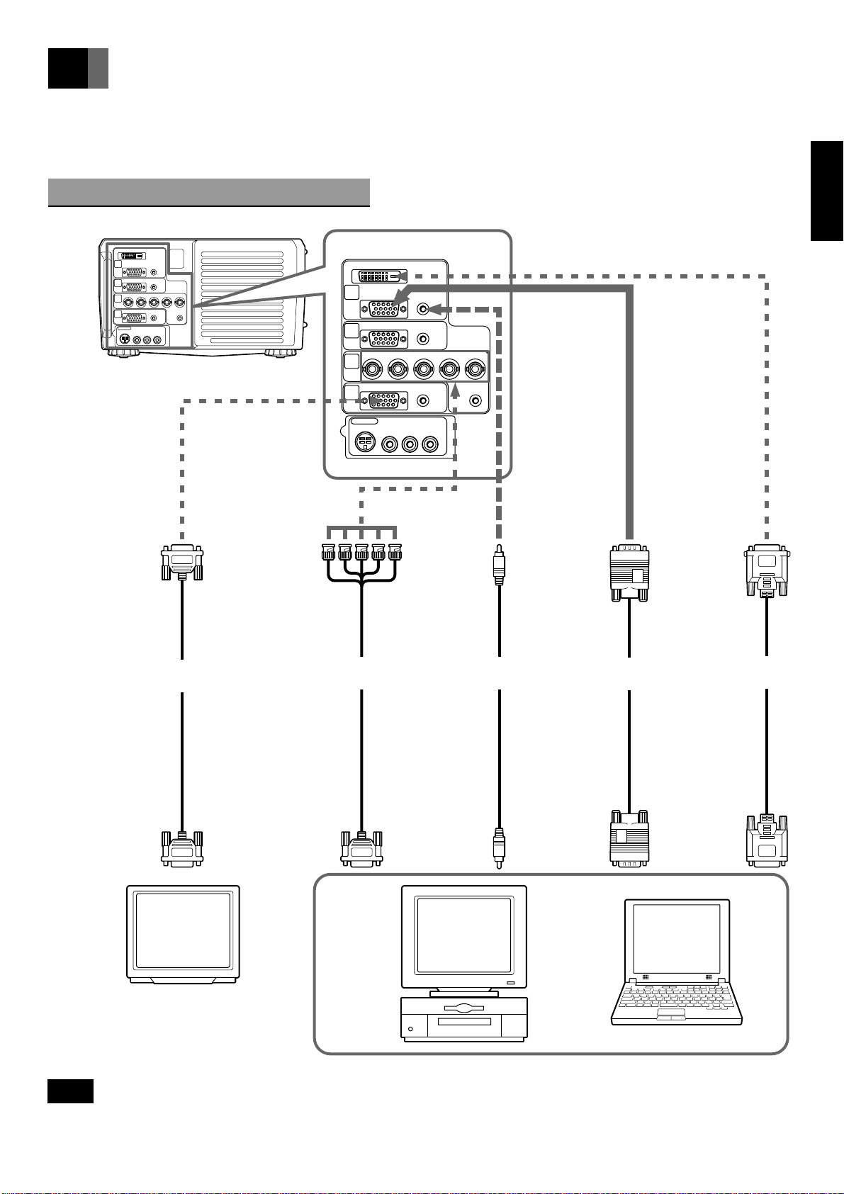
• This projector can be connected to a PC, TV, video deck, laser disk player, video camera, etc.
• Before making any connections or disconnections, make sure that the projector and the equipment to which it is connected are
turned off. Read the instruction manual supplied with the equipment to which the projector is connected.
AT Interchangeable Equipment
DIGITAL RGB
IN
PUT 1
RGB AUDIO
AUDIO
RGB
IN
PUT 2
G
Y HV
R Cr Pr B Cb Pb
IN
PUT 3
AUDIO
OUT
PUT
INPUT 4
S-VIDEO
VIDEO L R
AUDIORGB
AUDIO
[Projector Rear]
DIGITAL RGB
IN
PUT 1
RGB AUDIO
RGB
IN
PUT 2
R Cr Pr B Cb Pb
IN
PUT 3
OUT
PUT
AUDIO
Y HV
G
AUDIO
AUDIORGB
EnglishFrançaisDeutschEspañol
To RGB terminal
RGB cable
(optional)
To monitor RGB
input terminal
(screen image can be
viewed on monitor)
To 5-plug BNC
terminal
(used when using
5-plug BNC input
to prevent loss of
image quality)
To RGB output
terminal
INPUT 4
S-VIDEO
VIDEO L R
5-plug BNC
cable (optional)
AUDIO
To AUDIO
terminal
(sound can be
produced)
Stereo audio
cable (optional)
To sound output
terminal
To RGB terminal
(this connection
enables PC
images to be
projected)
RGB cable
(supplied)
To RGB output
terminal
To DIGITAL RGB
terminal
(can be used when
the PC has a DVI-D
terminal)
DIGITAL RGB
cable (optional)
To DIGITAL RGB
output terminal
(DVI-D terminal)
Note
• Use an RGB cable that matches the shape of the image output terminal on your PC.
• For details of the PC frequencies suitable for this projector, see the list of RGB-compatible frequencies on page 39.
En-17
Page 18
External Connection (To a PC) (continued)
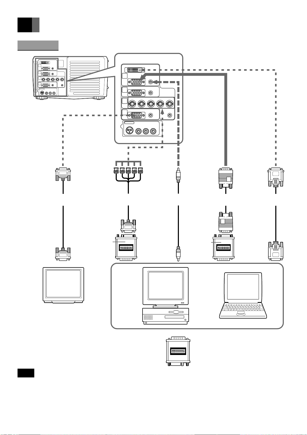
Macintosh
DIGITAL RGB
IN
PUT 1
RGB AUDIO
AUDIO
RGB
IN
PUT 2
G
Y HV
R Cr Pr B Cb Pb
IN
PUT 3
AUDIO
OUT
PUT
INPUT 4
AUDIO
S-VIDEO
VIDEO L R
[Projector Rear]
DIGITAL RGB
IN
PUT 1
RGB AUDIO
AUDIORGB
RGB
IN
PUT 2
R Cr Pr B Cb Pb
IN
PUT 3
OUT
PUT
AUDIO
Y HV
G
AUDIO
AUDIORGB
To RGB terminal
RGB cable
(optional)
To monitor RGB
input terminal
(screen image can be
viewed on monitor)
To 5-plug BNC
terminal
(used when using
5-plug BNC input
to prevent loss of
image quality)
To RGB output
terminal
MAC connector
(optional)
INPUT 4
S-VIDEO
VIDEO L R
5-plug BNC
cable (optional)
AUDIO
To AUDIO
terminal
(sound can be
produced)
Stereo audio
cable (optional)
To sound output
terminal
To RGB terminal
(this connection
enables PC
images to be
projected)
To RGB output
terminal
MAC connector
(optional)
RGB cable
(supplied)
To DIGITAL RGB
terminal
(can be used when
the PC has a DVI-D
terminal)
DIGITAL RGB
cable (optional)
To DIGITAL RGB
output terminal
(DVI-D terminal)
When using a MAC connector, set the dip switches as follows.
Mac 13" Mode (640 x 480) → Switches 1, 4, 6, 7 ON
Mac 16" Mode (832 x 624) → Switches 1, 3, 6, 7 ON
Mac 19" Mode (1024 x 768) → Switches 1, 2, 6, 7 ON
Mac 21" Mode (1152 x 870) → Switches 1, 2, 3, 4, 6, 7 ON
Note
• When connecting the projector to a Macintosh PC, be sure to use the optional MAC connector, otherwise a blank display may
result.
• When connecting the projector to a Macintosh notebook PC, in addition to the optional MAC connector, a special adapter
(available on the market) may be necessary.
• Use an RGB cable that matches the shape of the image output terminal of your PC.
• For details of the PC frequencies suitable for this projector, see the list of RGB-compatible frequencies on page 39.
En-18
Page 19
External Connection (To a Video/Laser Disk/DVD)
DIGITAL RGB
IN
PUT
1
RGB AUDIO
AUDIO
RGB
IN
PUT 2
Y HV
R Cr Pr B Cb Pb
G
IN
PUT 3
AUDIO
OUT
PUT
INPUT 4
S-VIDEO
VIDEO L R
[Projector Rear]
AUDIORGB
AUDIO
DIGITAL RGB
IN
PUT 1
IN
PUT 2
R
IN
3
PUT
OUT
PUT
RGB AUDIO
RGB
G
Y
Cr Pr
AUDIO
B
Cb Pb
AUDIO
EnglishFrançaisDeutschEspañol
HV
AUDIORGB
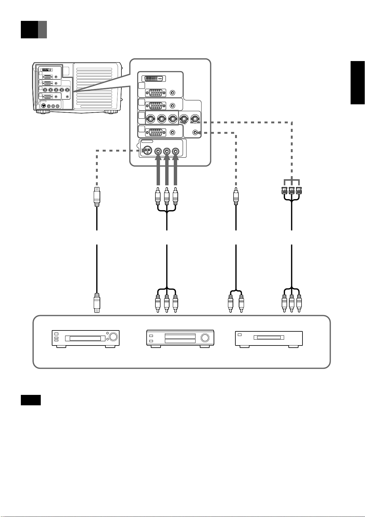
To S-VIDEO terminal
(used to connect
equipment with S image
output terminal)
S terminal cable
(optional)
To S image
output terminal
INPUT 4
S-VIDEO
To VIDEO & AUDIO
L/R terminals
(this connection
enables image and
sound output)
To video/audio
output terminals
AUDIO
VIDEO L R
AV cable
(supplied)
To AUDIO terminal
(used to connect
equipment with
component output
terminal)
Stereo audio
cable (optional)
To audio output terminal
(on equipment with
component output
terminal)
To Cr, Y, Cb
terminal
(used to connect
equipment with
component output
terminal)
RCA-BNC
cable (optional)
To Cr, Y, Cb terminal
(on equipment with
component output
terminal)
Laser disk player Video deck
DVD player
Note
• Images input by component video input to INPUT 3 terminal can be viewed on a monitor TV connected to the RGB output
terminal. Images input to the VIDEO INPUT terminal cannot be viewed on the monitor TV.
• When connecting the projector to equipment with stereo sound output, be sure to connect the L/R audio output or stereo audio
cable. When there is no image input (blue background screen), there will be no audio output.
• For component video input, it is necessary to set the component signals separately. For details, see page 31.
En-19
Page 20
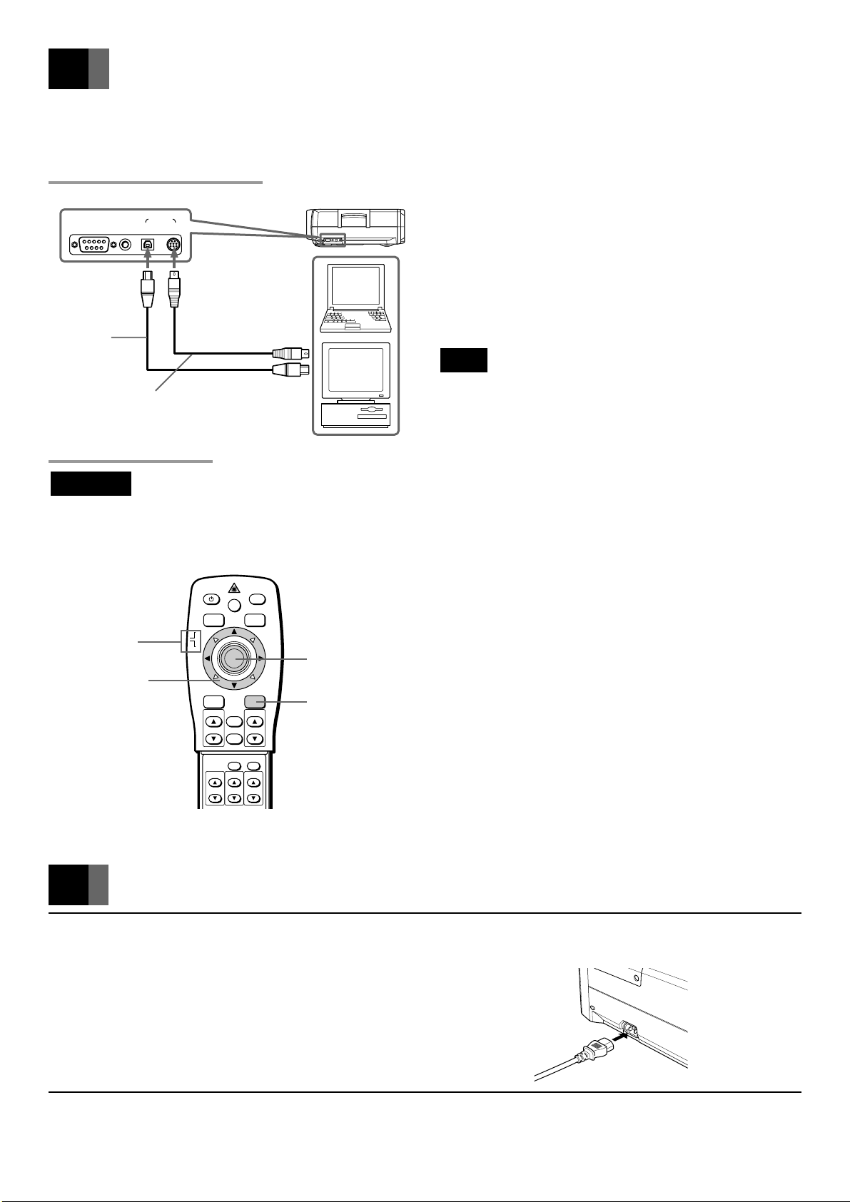
Mouse Functions
By connecting the PC mouse terminal and projector mouse terminal, the projector remote control unit can be used instead of the PC
mouse.
Connecting the Mouse
[Projector right side]
PS-232C
To MOUSE
USB terminal
USB mouse
connection
cable (optional)
PS/2 mouse
connection cable
(supplied)
USB PS/2
To MOUSE PS/2
terminal
MOUSE
WIRED
REMOTE
Mouse Functions
Important
To mouse (PS/2)
terminal
To mouse (USB)
terminal
■ Connecting to AT interchangeable equipment
Connect a PS/2 mouse or USB mouse. (The PS/2 mouse
cable is supplied, but the USB mouse cable is optional.)
■ Connecting to a Macintosh PC
Connect a USB mouse or ADB mouse. (Both the USB mouse
cable and Mac mouse cable for the ADB mouse are op
tional.)
Note
• When connecting the ADB mouse, use the optional Mac
mouse cable instead of the PS/2 mouse cable.
• Set the slide switch on the remote control unit to MOUSE. If the switch is set on PJ (projector), the following operations
cannot be performed.
■ R-MOUSE button
The R-MOUSE button on the right of the remote control unit
corresponds to the right button on a mouse with two click
buttons.
■ L-MOUSE button
The L-MOUSE button in the center of the remote control
unit corresponds to the left button on a mouse with two click
buttons.
■ Moving the Cursor
When the left, right, up, down and diagonal mouse pointer
buttons are pressed, the cursor moves in the designated
direction on the screen.
■ Select and Decide
Move the cursor and press the L-MOUSE button.
Slide switch
Mouse pointer
buttons
POWER
RGB
MOUSE
PJ
MENU
ZOOM-PAN
ZOOM
LASER
VIDEO
ENTER/R-MOUSE
VOLUMESOURCE
CANCEL
STATUS
AUTO
KEYSTONE
FOCUS
MUTE
L-MOUSE button
R-MOUSE button
■ Drag
While pressing the L-MOUSE button, press the mouse
pointer buttons in the desired drag direction.
Connecting the Power Source
1
2
En-20
Plug the power cable (supplied) into the power terminal on the left side of
the projector.
Insert the power plug into the power socket.
The POWER-ON monitor lights red and the projector is in standby status.
Page 21
Basic Operation
VOLUME
ENTERMENU
STATUSAUTO
VIDEORGB
POWER
MUTE
KEY STONE
FOCUSZOOM
POWER button
POWER
MOUSE
PJ
MENU
ZOOM-PAN
RGB
ZOOM
LASER
VIDEO
ENTER/R-MOUSE
VOLUMESOURCE
CANCEL
STATUS
AUTO
KEYSTONE
FOCUS
MUTE
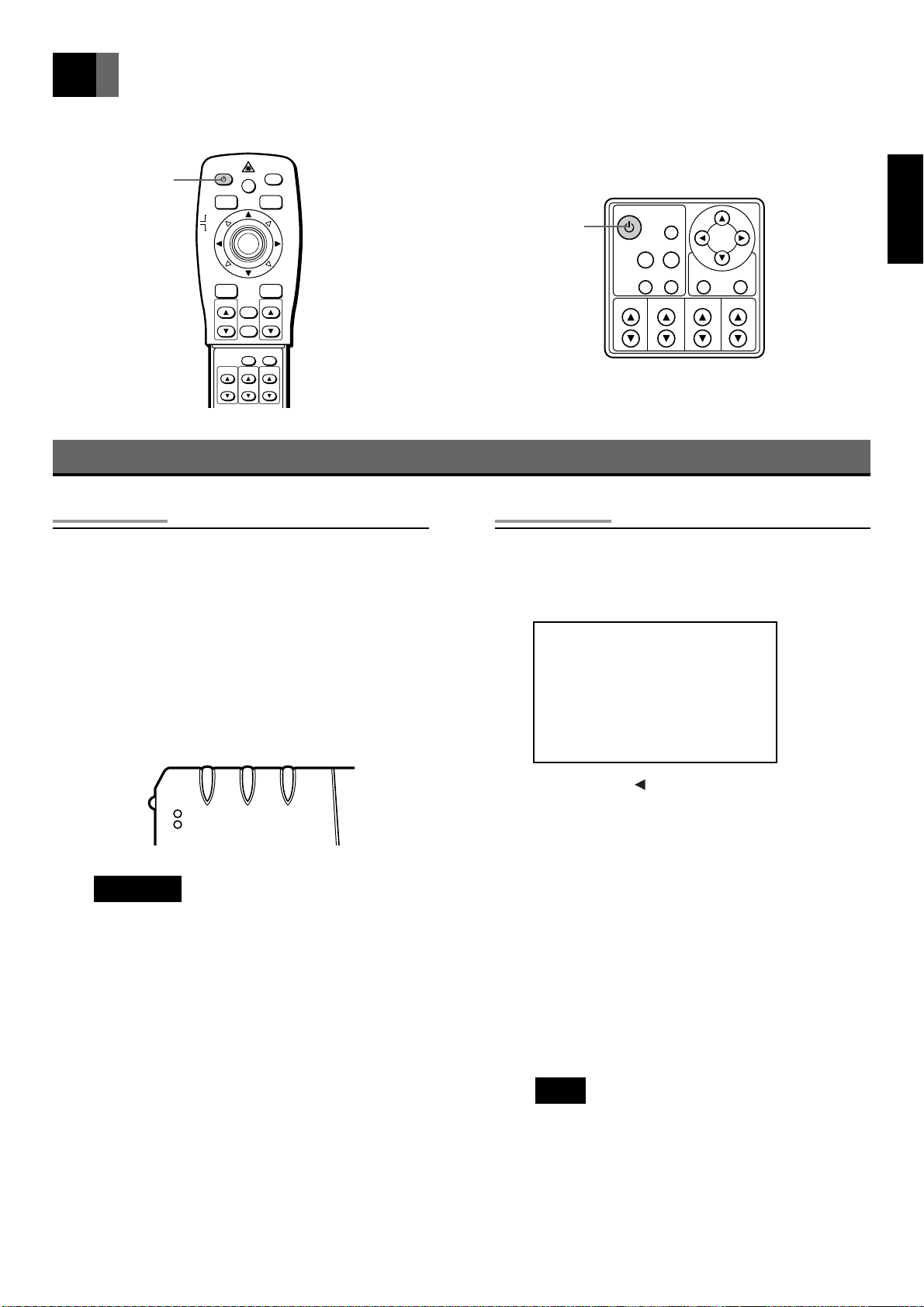
Turning the Projector On and Off
Turning On
Press the POWER button.
•
The POWER-ON monitor lights green and the lamp
comes on.
POWER-ON monitor displa y on pr ojector front
Green : In operation
Red : Standby status
Orange : Lamp cooling
(POWER-ON monitor)
POWER button
Turning Off
Press the POWER button.
•
The confirmation screen is displayed.
POWER BUTTON WAS PUSHED!
Push POWER button or
Move the cursor to “Power Off”
and push ENTER button to turn
projector off.
Power Off Cancel
EnglishFrançaisDeutschEspañol
STAND-BY TEMP LAMP
POWER-ON
Important
• Always remove the lens cap before turning the
lamp on, otherwise the lens cap may become
deformed.
• The power cannot be turned off by pressing the
POWER button again for 1 minute after the lamp
comes on.
• Turn the projector on before turning the PC on,
other wise the image display and mouse functions
(except when using an USB mouse) may be
adversely affected.
If you press the adjustment button to select [Power
Off] and then press the ENTER button, the power will
be turned off. You can also press the POWER button
again to turn the power off.
When [Power Off] is selected, the following operations are performed.
1. The POWER-ON monitor changes from red to
orange. (Lamp is cooling)
2. The cooling fan rotates for 2 minutes. The buttons
on the projector operation panel and the remote
control unit cannot be operated for 1 minute after
cooling of the lamp starts. (Operation can be
restarted after 1 minute.)
3. When cooling is finished, the fan stops, the
POWER-ON monitor changes from orange to red,
and the projector is in standby status.
Note
• The cooling fan continues to rotate while the
inside of the projector is hot, even after the
POWER button is pressed. Do not unplug the
power cable from the socket while the cooling
fan is rotating (approx. 2 minutes).
En-21
Page 22
Basic Operation (continued)
VOLUME
ENTERMENU
STATUSAUTO
VIDEORGB
POWER
MUTE
KEY STONE
FOCUSZOOM
POWER
RGB button
MOUSE
PJ
ZOOM-PAN
ZOOM buttons
RGB
MENU
ZOOM
LASER
VIDEO
ENTER/R-MOUSE
VOLUMESOURCE
CANCEL
STATUS
AUTO
KEYSTONE
FOCUS
MUTE
VIDEO button
FOCUS buttons
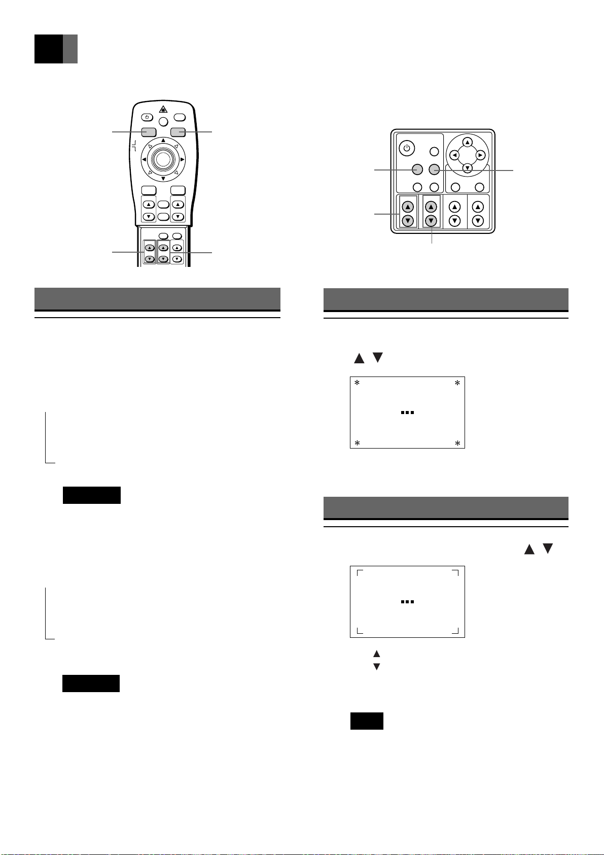
Selecting the Desired Image
Press the RGB button or VIDEO
•
button.
The input source switches as shown below each time
the RGB button is pressed.
INPUT 1 - RGB [DIGITAL RGB or RGB (analog)]
➝
➝
RGB button
ZOOM buttons
Focusing
Press the FOCUS buttons
•
(
, ).
VIDEO button
FOCUS buttons
Focus
INPUT 2 - RGB
➝
INPUT 3 - RGB
Important
• Select digital or analog INPUT 1 signal on the
menu displayed. (See page 30)
The input source switches as shown below each time
the VIDEO button is pressed.
VIDEO
➝
➝➝
S-VIDEO
INPUT 3 - COMP (Standard or high definition
component)
Important
• Select SD (standard) or HD (high definition) for
the INPUT 3 component input signal. (See page
31)
The input source display is exited soon after the
selection is made.
The operation screen is exited soon after making the
adjustment.
Adjusting the Size of the Picture
Press the ZOOM buttons ( , ).
•
Zoom
Press to increase the size of the picture.
Press to decrease the size of the picture.
The operation screen is exited soon after making the
adjustment.
Note
• Match the size of the screen used to the projection distance. See “Setting Up” on page 15.
En-22
Page 23
VOLUME
ENTERMENU
STATUSAUTO
VIDEORGB
POWER
MUTE
KEY STONE
FOCUSZOOM
Mouse pointer
buttons
ZOOM-PAN buttons
CANCEL button
POWER
MOUSE
PJ
MENU
ZOOM-PAN
ZOOM
RGB
LASER
VIDEO
ENTER/R-MOUSE
VOLUMESOURCE
CANCEL
STATUS
AUTO
KEYSTONE
FOCUS
MUTE
MUTE button
VOLUME buttons
MUTE button
EnglishFrançaisDeutschEspañol
VOLUME buttons
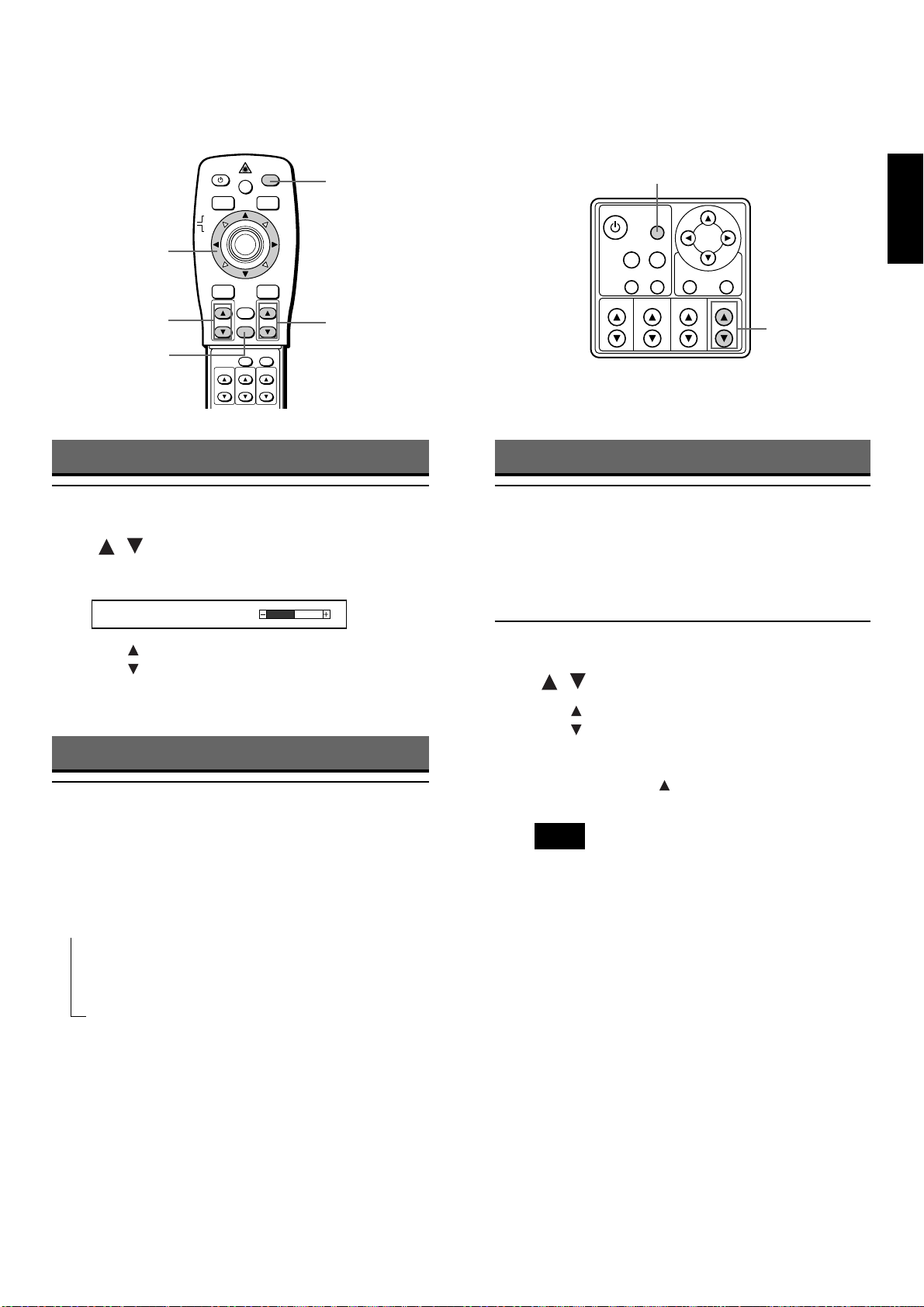
Adjusting the Volume
Press the VOLUME buttons
•
(
, ).
The adjustment screen is displayed.
Volume
50
Press to increase the volume.
Press to decrease the volume.
The screen is exited soon after completing adjustment.
Muting the Sound and Image
Press the MUTE button.
•
The sound and image can be temporarily muted by
pressing the MUTE button.
Mute status switches as shown below when the
MUTE button is pressed.
Sound muted ([MUTE] appears on screen)
➝
➝➝
Partially Enlarging the Picture
Move the cursor to the area you
1
wish to enlarge using the mouse
pointer buttons on the remote
control unit.
Press the ZOOM-PAN buttons
2
(
Press to enlarge the image.
Press to return the enlarged image to its original
size.
The area can be enlarged 1 – 100 times (area ratio) in
20 stages each time is pressed.
).
,
Note
• Press the CANCEL button to cancel partial
enlargement and return to normal status.
• The mode is canceled when the menu screen is
displayed or when the input source is switched.
Sound and image muted
Normal status
En-23
Page 24
Basic Operation (continued)
VOLUME
ENTERMENU
STATUSAUTO
VIDEORGB
POWER
MUTE
KEY STONE
FOCUSZOOM
SOURCE button
AUTO button
POWER
MOUSE
PJ
MENU
ZOOM-PAN
RGB
ZOOM
LASER
VIDEO
ENTER/R-MOUSE
VOLUMESOURCE
CANCEL
STATUS
AUTO
KEYSTONE
FOCUS
MUTE
STATUS button
KEYSTONE buttons
Displaying Projector Status
Press the STATUS button.
•
The following statuses are displayed when the
STATUS button is pressed.
1 Present input source
2 Image mode in present input source
3 Lamp timer
4 Resizing status
5 Mute status
6 Volume status
7 Brightness
8 Contrast status
Press the STATUS button again to return to the
original screen.
AUTO button
KEYSTONE buttons
STATUS button
Automatically Adjusting the Position
Press the AUTO button.
•
The horizontal position, vertical position, picture
width and picture blurring are automatically adjusted.
Displaying the Input Source
Press the SOURCE button.
•
The input source and image mode are displayed.
Press the SOURCE button again to return to the
original screen. (If no keys are pressed for xxx
seconds, the display returns to the original screen.)
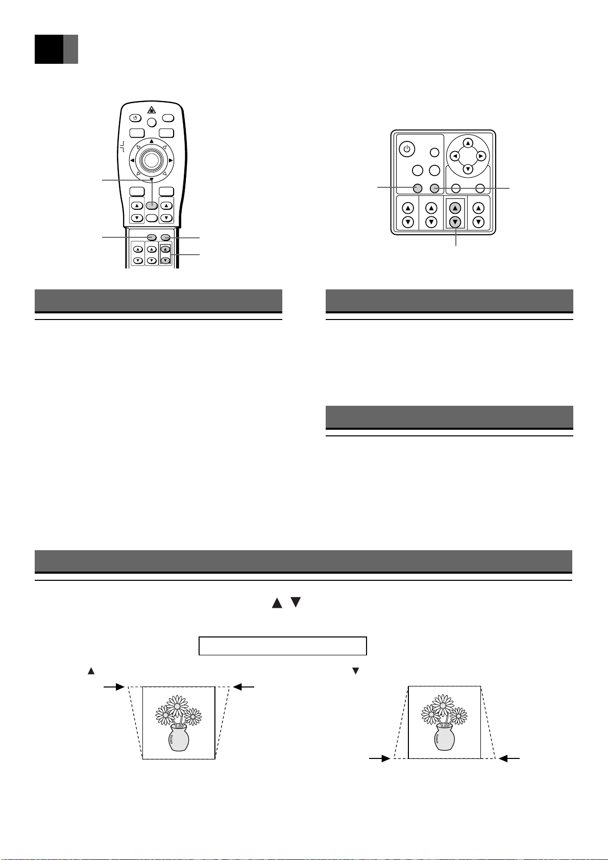
Adjusting Distortion of the Image Trapezoid
Press the KEYSTONE buttons ( , ).
•
The adjustment screen is displayed.
En-24
Keystone correction
When is pressed, the upper part of the image is corrected. When is pressed, the lower part of the image is corrected.
The screen is exited soon after adjustment is completed. (It can also be exited by pressing the MENU button.)
0
Page 25
Operating the Menu Screens
VOLUME
ENTERMENU
STATUSAUTO
VIDEORGB
POWER
MUTE
KEY STONE
FOCUSZOOM
Slide switch
MENU button
POWER
MOUSE
PJ
MENU
ZOOM-PAN
RGB
ZOOM
LASER
VIDEO
ENTER/R-MOUSE
VOLUMESOURCE
CANCEL
STATUS
AUTO
KEYSTONE
FOCUS
MUTE
Adjustment buttons
( , , , )
ENTER button
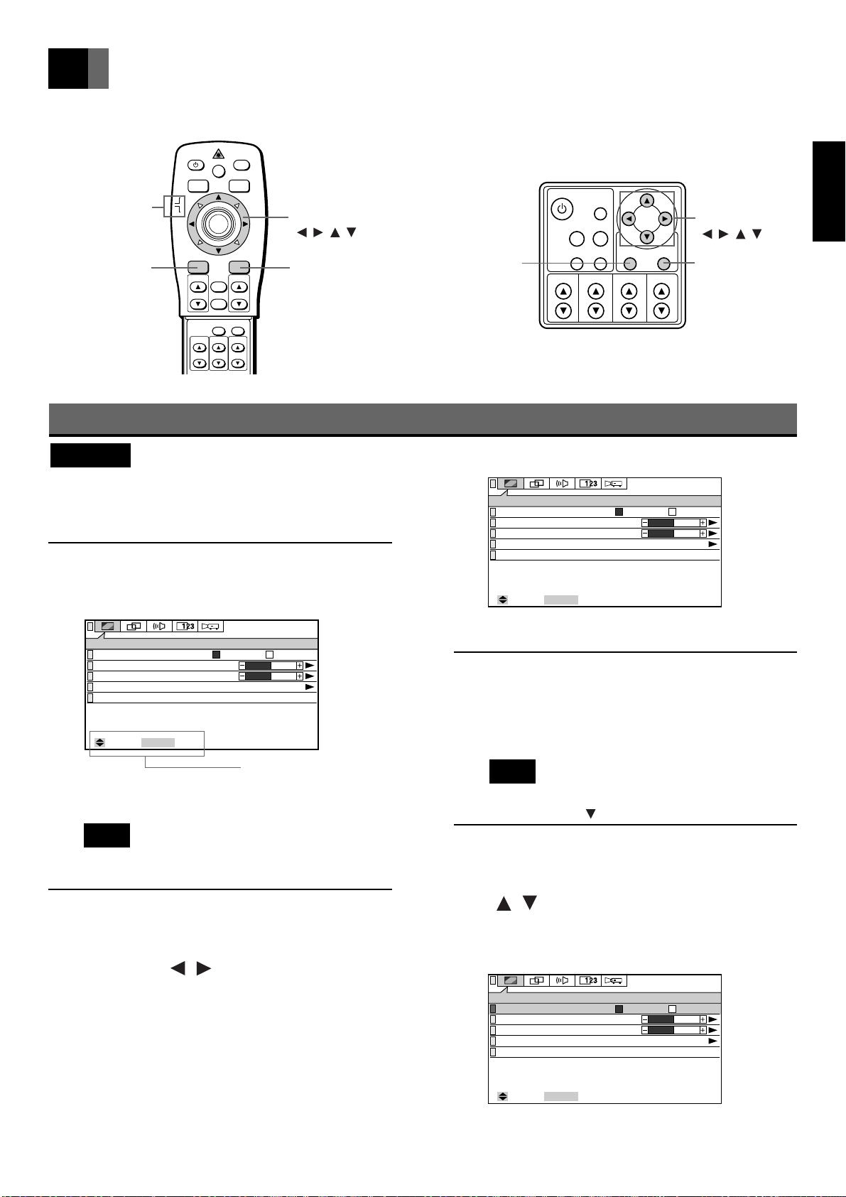
Operating the Menu Screens
Important
• Set the slide switch on the remote control unit to PJ
(Projector). If the switch is set on MOUSE, the
following operations cannot be performed.
Press the MENU button.
1
The Menu screen is displayed.
IMAGE
Luminance Mode
Brightness
Contrast
Factory Default
Next Page
ENTER
: Select
: Next
Normal Low
0
0
Adjustment buttons
( , , , )
ENTER buttonMENU button
IMAGE
Luminance Mode
Brightness
Contrast
Factory Default
Next Page
ENTER
: Select
: Next
Normal Low
0
0
Example: Select the IMAGE menu.
Press the ENTER button.
3
The screen for selecting the item you wish to adjust is
displayed.
EnglishFrançaisDeutschEspañol
Operation bar
Example: When RGB is selected for the input source
Note
• The operation bar is displayed at the bottom of
the screen.
Select the menu item you wish
2
to adjust with the adjustment
buttons ( , ) on the remote
control unit or projector.
The selected menu screen is displayed.
The menu screen switches as shown below each time
the buttons are pressed.
IMAGE (P.27) POSITION (P.29)
➝
➝
INSTALLATION (P.32) DISPLAY (P.30)
➝
➝
SOUND (P.30)
➝
➝
➝
➝
➝
➝
Note
• The same operation can be performed by
pressing the adjustment button.
Select the item you wish to ad-
4
just with the adjustment buttons
( , ).
The green button on the left of the selected item
lights up.
IMAGE
Luminance Mode
Brightness
Contrast
Factory Default
Next Page
ENTER
: Select
: Next
Example : Select Luminance Mode.
Normal Low
0
0
En-25
Page 26
Operating the Menu Screens (continued)
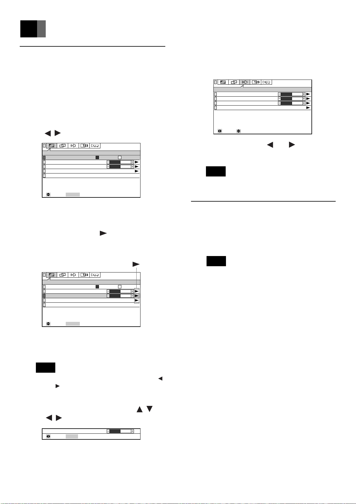
Making the Desired Adjust/Set
5
up
5-3 When selecting the SOUND
menu in Step 3 and adjusting
the V olume/T reble/Bass
5-1 When selecting the item you
wish to adjust ([OK/Cancel],
[Normal/Low], etc.)
• Select with the adjustment buttons
, ).
(
IMAGE
Luminance Mode
Brightness
Contrast
Factory Default
Next Page
ENTER
: Select
Example: Select [Normal/Low] in [Luminance
Mode].
: Next
Normal Low
0
0
5-2 When there is a mark (to next
screen) at the right of the item
you wish to adjust
SOUND
Volume
Treble
Bass
Factory Default
: Select: Adjust
50
0
0
• Adjust using the and adjustment
buttons.
Note
• Volume/Treble/Bass can be adjusted on the Menu
screen.
Press the MENU button to return
6
to the previous screen.
Each time the MENU button is pressed, the display
reverts one screen.
Note
IMAGE
Luminance Mode
Brightness
Contrast
Factory Default
Next Page
ENTER
: Select
: Next
Normal Low
0
0
Example: Select [Contrast].
(1) Press the ENTER button to display the
adjust/select/set up screen.
Note
• The same operation is possible by pressing the
and adjustment buttons.
(2) Make the desired Adjust/Selet/Set up
with the adjustment buttons (
, ,
, ).
Contrast
MENU
: Return : Adjust
0
• When [ENTER : Decide] is displayed on the
operation bar and ENTER is pressed, the item is
adjusted and the display returns to the previous
screen.
En-26
Page 27
Adjusting the IMAGE
0
0
0
0
IMAGE
Before Page
Color Temp.
Gain : Red
Gain : Green
Gain : Blue
Save to Memory
Load from Memory
: Select
ENTER
: Next
0
Sharpness
MENU
: Return : Adjust
0
Color
MENU
: Return : Adjust
0
Tint
MENU
: Return : Adjust
ENTER
: Decide
: Set up
OK Cancel
Default Factory Setting?
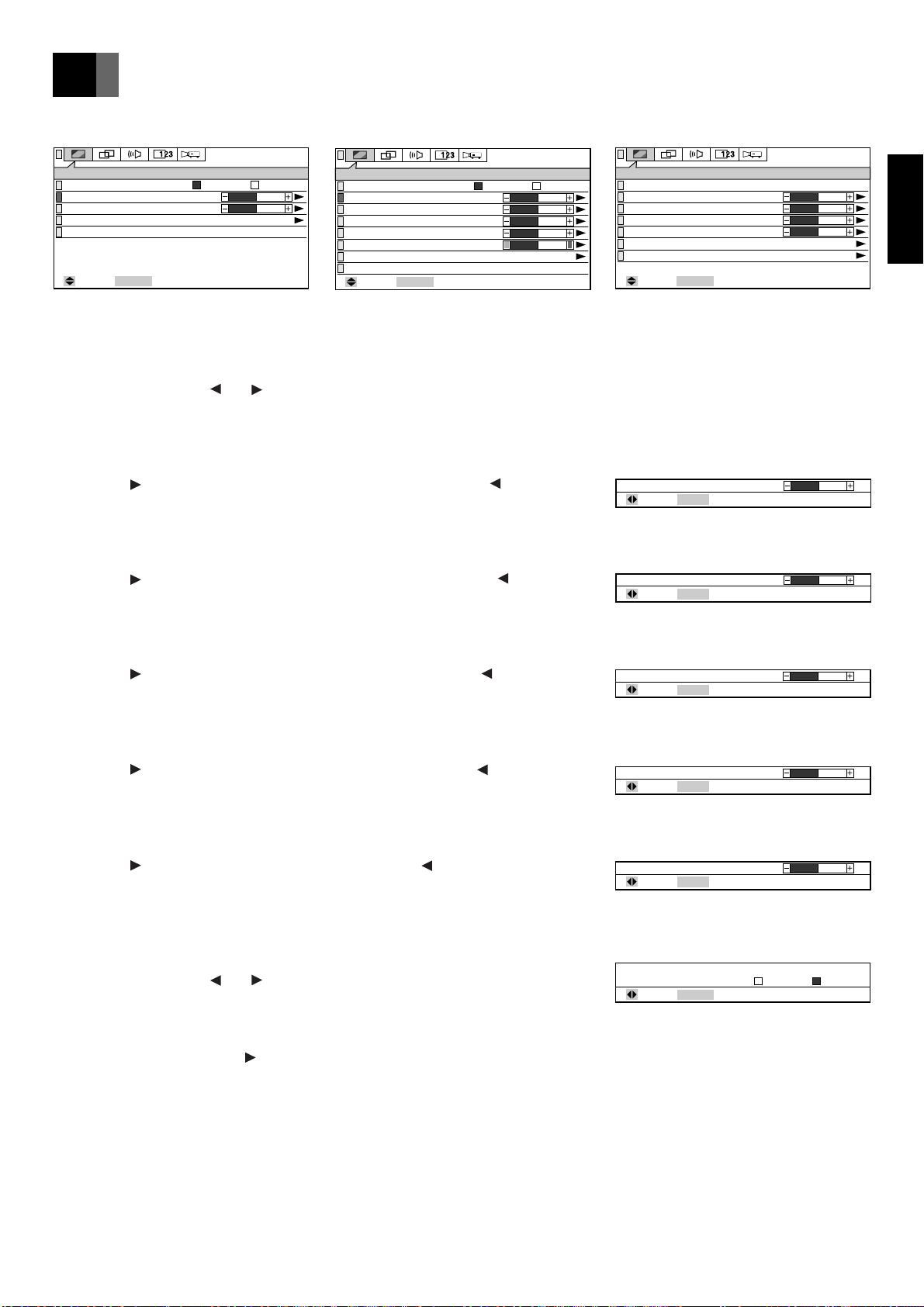
You can adjust, select and set up the following items on the IMAGE Menu.
IMAGE
Luminance Mode
Brightness
Contrast
Factory Default
Next Page
ENTER
: Select
: Next
(1st page of RGB IMAGE Menu)
Normal Low
0
0
IMAGE
Luminance Mode
Brightness
Contrast
Sharpness
Color
Tint
Factory Default
Next Page
: Select
ENTER
: Next
(1st page of VIDEO IMAGE Menu)
■ Luminance Mode
You can set the luminance of the projector on [Normal] or [Low].
Select by pressing the and adjustment buttons.
The factory default setting is [Normal].
■ Brightness
You can adjust the brightness of the picture.
Press the adjustment button to make the picture brighter, and the
button to make it darker.
■ Contrast
You can adjust the contrast of the picture.
Press the adjustment button to make the contrast stronger, and the
button to make it weaker.
Normal Low
0
0
0
0
0
(2nd page of IMAGE Menu)
Brightness
Contrast
MENU
MENU
: Return : Adjust
: Return : Adjust
EnglishFrançaisDeutschEspañol
0
0
■ Sharpness (VIDEO)
You can adjust the image quality.
Press the adjustment button to make the image sharper, and the button
to make it softer.
■ Color (VIDEO only)
You can adjust the depth of the colors.
Press the adjustment button to make the colors deeper, and the button
to make them paler.
■ Tint (VIDEO only)
You can adjust the tint.
Press the adjustment button for a reddish tint, and the button for a
greenish tint.
■ Factory Default
You can return the image adjustment values to their standard status (factory
default settings).
Select by pressing the and adjustment buttons, and decide by pressing
the ENTER button.
■ Next Page
Press the ENTER button (or ) to proceed to the second page of the
IMAGE Menu.
■ Before Page
Press the MENU button to return to the first page of the IMAGE Menu.
En-27
Page 28
Adjusting the Image (continued)
0
Color Temp.
MENU
: Return : Adjust
0
Gain : Blue
MENU
: Return : Adjust
1 2 3 4
0
(0,0,0)
0
0
0
0
0
10
10
10
10
10
10
10
Load from Memory
Load
Cancel
Brightness
Contrast
Sharpness
Color
Tint
ENTER
: Decide
: Select : Set up
Color Temp.
Gain : (Red,Green,Blue)
Memory1 ValuePresent Value
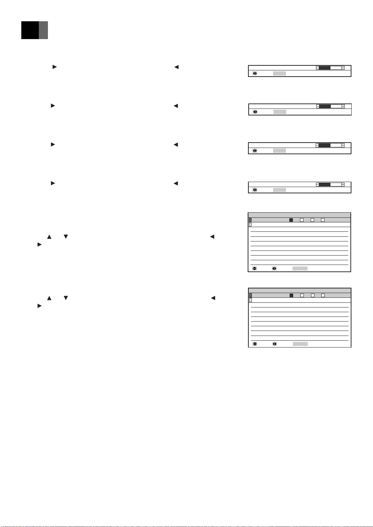
■ Color Temp.
You can adjust the color temperature.
Press the adjustment button for a reddish tinge, and the button for a
blueish tinge.
■ Gain: Red
You can adjust the strength of the red color.
Press the adjustment button to make it stronger, and the button to make
it weaker.
■ Gain: Green
You can adjust the strength of the green color.
Press the adjustment button to make it stronger, and the button to make
it weaker.
■ Gain: Blue
You can adjust the strength of the blue color.
Press the adjustment button to make it stronger, and the button to make
it weaker.
■ Save to Memory
You can save the adjusted values in memory 1, 2, 3 or 4.
You can set INPUT 1, 2 and 3 and VIDEO INPUT (including S-video/
component video).
Use the and adjustment buttons to select [Save] or [Cancel], and the
and buttons to select memory 1, 2, 3 or 4, then press the ENTER button
to execute.
Gain : Red
Gain : Green
Save to Memory
Save
Cancel
Brightness
Contrast
Sharpness
Color
Tint
Color Temp.
Gain : (Red,Green,Blue)
MENU
MENU
: Select : Set up
: Return : Adjust
: Return : Adjust
0
0
1 2 3 4
Memory1 ValuePresent Value
0
0
0
0
0
0
(0,0,0)
ENTER
: Decide
10
10
10
10
10
10
10
■ Load from Memory
You can load the adjusted values saved in the memory .
Use the and adjustment buttons to select [Load] or [Cancel], and the
and buttons to select memory 1, 2, 3 or 4, then press the ENTER button
to execute.
En-28
Page 29
Adjusting the POSITION
MENU
: Return : Set up
Horiz. Position
Vert. Position
POSITION
0
Pixel Tracking
MENU
: Return : Adjust
0
Pixel Phase
MENU
: Return : Adjust
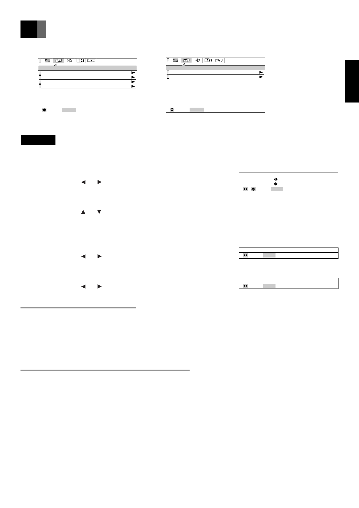
You can adjust, select and set up the following items from the POSITION Menu.
POSITION
Horiz. Position
Vert. Position
Pixel Tracking
Pixel Phase
: Select
0
0
ENTER
: Next
(RGB POSITION Menu)
POSITION
Horiz. Position
Vert. Position
ENTER
: Select
(VIDEO POSITION Menu)
: Next
Important
• The position cannot be adjusted when DIGITAL RGB is selected as the input source.
■ Horiz. Position
You can adjust the horizontal position of the image.
Adjust by pressing the and adjustment buttons.
■ Vert. Position
You can adjust the vertical position of the image.
Adjust by pressing the and adjustment buttons.
(If you move the image up a long way, it may become distorted, but this is
not a failure.)
■ Pixel Tracking (RGB only)
You can adjust the width of the picture.
Adjust by pressing the and adjustment buttons.
EnglishFrançaisDeutschEspañol
■ Pixel Phase (RGB only)
You can adjust the degree of blurring of the picture.
Adjust by pressing the and adjustment buttons.
To reduce blurring and noise
If you adjust the [Pixel Phase] after adjusting [Pixel Tracking], it is easier to find the optimum point at which there is minimum
blurring or noise.
When adjusting [Pixel Tracking], the point at which the vertical belt of noise disappears when you display the [Quit Windows]
screen from the Windows 95/98 Start Menu or the checkered pattern, is the optimum adjustment value.
When adjusting the [Pixel Phase], the point at which the horizontal blurring or noise disappears when you display the [Quit
Windows] screen from the Windows 95/98 Start Menu or the checkered pattern, is the optimum adjustment value.
When automatically adjusting the position
• The horizontal position, vertical position, picture width and picture blurring are adjusted automatically.
• This adjustment will be executed when the following operations are performed.
1) when the power is turned on and the lamp lights
2) when the type of input source signal is changed while the lamp is on
3) when the input selector button is pressed while the lamp is on.
• The [EXECUTING] message is displayed on the screen during automatic adjustment.
• The picture may appear distorted during automatic adjustment, but this is not a malfunction.
• Correct adjustment may fail to be performed due to the input signal and input image from the PC. In this case, adjust manually.
• Adjust the position automatically when you have a bright projected image.
Adjustment is only possible when the input source is set on INPUT 1, 2 or 3. It cannot be performed when there is no signal.
([No Signal] is displayed.)
En-29
Page 30
Adjusting the SOUND
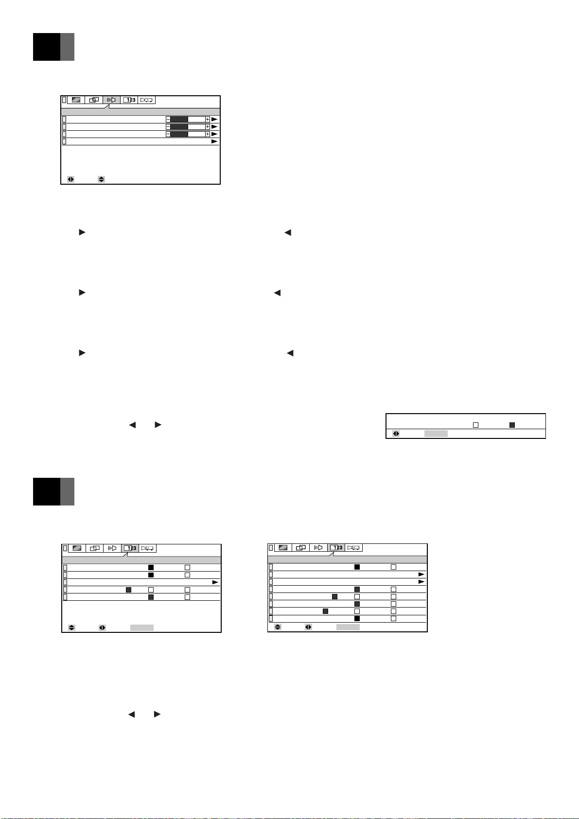
You can adjust and set up the following items from the SOUND Menu.
SOUND
Volume
Treble
Bass
Factory Default
: Select: Adjust
■ Volume
You can adjust the volume.
Press the adjustment button to increase the volume, and the button to
decrease the volume.
■ Treble
You can adjust the treble level.
Press the adjustment button to increase the level, and the button to
decrease the level.
■ Bass
You can adjust the power of the bass sounds.
Press the adjustment button to increase the strength, and the button to
decrease the strength.
50
0
0
■ Factory Default
You can return the adjusted sound values to their standard status (factory
default settings).
Select by pressing the and adjustment buttons, and decide by pressing
the ENTER button.
Setting the DISPLAY
You can select and set up the following items from the DISPLAY menu.
DISPLAY
Resizing
INPUT1 Mode
Language
Source Status
Blank Screen
: Select : Set up
On Off
Analog Digital
English
All
No Signal No Display
Blue Black
ENTER
: Next
(RGB DISPLAY Menu)
■ Resizing
You can select whether to display the picture in real mode (with the same
resolution as the input signal) or in resizing mode (converting it to the same
XGA size as the LCD panel).
Select by pressing the and adjustment buttons.
The factory default setting is [On].
DISPLAY
Resizing
Language
Video Standard
Componet Input
Source Status
Blank Screen
Overscan
3D Y/C
: Select : Set up
(VIDEO DISPLAY Menu)
Default Factory Setting?
: Set up
On
English
AUTO
SD HD
All
No Signal No Display
ENTER
Blue
On Off
: Next
Standard Medium Maximum
Off
Black
ENTER
: Decide
OK Cancel
En-30
Page 31
Setting the DISPLAY
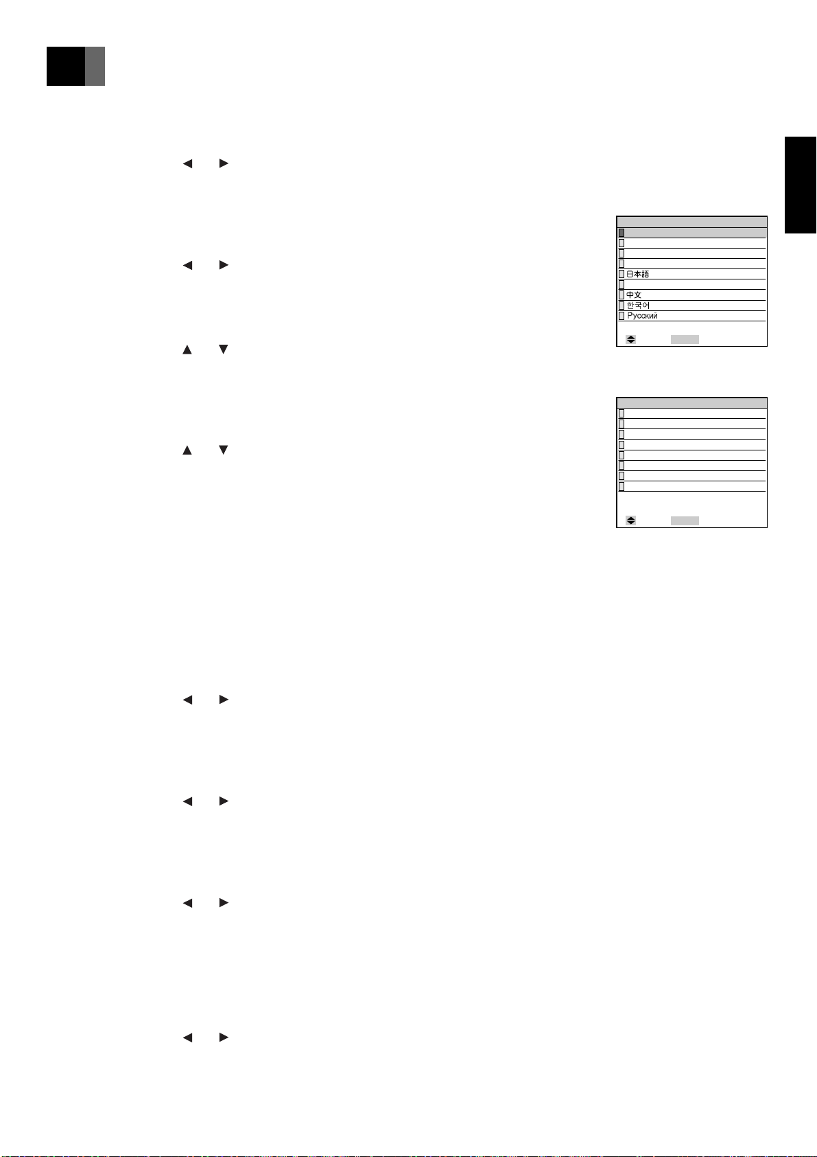
■ INPUT 1 Mode (RGB only)
You can select the DIGITAL RGB terminal or RGB (analog) terminal for
the INPUT 1 input terminal.
Select by pressing the and adjustment buttons.
The factory default setting is [Analog].
■ Component Input (VIDEO only)
You can select HD (High Definition: 720P, 1080I) or SD (Standard: 480P,
480I) for the INPUT 3 component input signal.
Select by pressing the and adjustment buttons.
The factory default setting is [SD].
■ Language
You can select the language of the menu display.
Select by pressing the and adjustment buttons.
■ Video Standard (VIDEO only)
You can select the video broadcasting format. For normal use, set on
[AUTO]. When set on [WIDE], the picture becomes elongated sideways
(the aspect ratio of the picture is about 16:9).
Select by pressing the and adjustment buttons.
The factory default setting is [AUTO].
■ Source Status
You can select the method of displaying the status of the input source as
follows.
1) All
The source and mode status are displayed. The display disappears
after a few seconds. When there is no signal, the [No Signal]
message is constantly displayed.
2) No Signal
The [No Signal] message is constantly displayed only when there is
no input signal.
3) No Display
The input source status is not displayed.
Select by pressing the and adjustment buttons.
The factory default setting is [All].
Language
English
Français
Deutsch
Español
Italiano
MENU
: Select
(Language)
Video Standard
AUTO
WIDE
NTSC
PAL
SECAM
PAL–M
PAL–N
NTSC–4.43
MENU
: Select
(Video Standard)
EnglishFrançaisDeutschEspañol
: Return
: Return
■ Blank Screen
You can select whether to have blue or black for the background color when
there is no image input signal.
Select by pressing the and adjustment buttons.
The factory default setting is [Blue].
■ Overscan
When there is interference at the top of the video screen, etc., you can
adjust the picture so that that part is not visible.
Select by pressing the and adjustment buttons.
The factory default setting is [Standard].
■ 3D Y/C
In the case of still images, the image becomes clearer when set on [On].
In the case of VTR (moving images), if the image is distorted, set on [Off].
This function can only be enabled when an NTSC video signal is input into
the VIDEO terminal for VIDEO INPUT.
Select by pressing the and adjustment buttons.
The factory default setting is [On].
En-31
Page 32
Setting the INSTALLATION
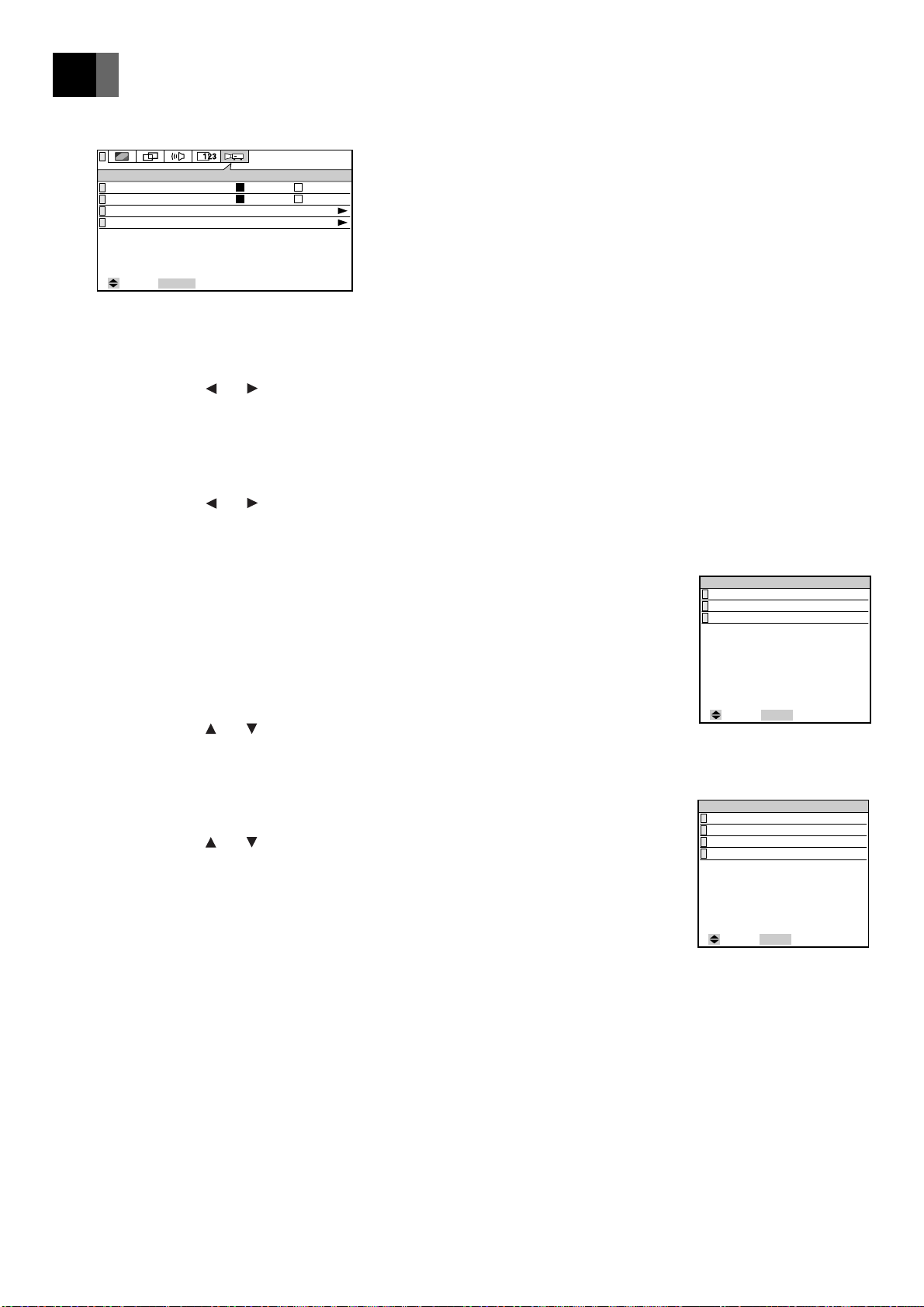
You can adjust and select the following items from the INSTALLATION Menu.
INSTALLATION
Auto Power Up
Auto Lamp Off
Remote Control
Reverse Mode
: Select
ENTER
: Next
Auto Manual
On Off
Rear & Front
Normal
■ Auto Power Up
You can set whether or not the lamp comes on automatically when the
power plug is inserted in the socket.
Select by pressing the and adjustment buttons.
The factory default setting is [Auto].
■ Auto Lamp Off
You can set whether or not the lamp goes off when there is no image input
signal for about 20 minutes.
Select by pressing the and adjustment buttons.
The factory default setting is [On].
■ Remote Control
You can select use of the wireless remote control unit light receivers on the
front and rear of the projector from the following.
1) Rear & Front
The remote control signal can be received from the front and rear.
2) Rear
The remote control signal can be received from the rear only.
3) Front
The remote control signal can be received from the front only.
Select by pressing the and adjustment buttons.
The factory default setting is [Rear & Front].
Remote Control
Rear & Front
Rear
Front
MENU
: Select
(Remote Control)
: Return
■ Reverse Mode
You can set vertical or horizontal inversion of the image from the settings
shown on the right.
Select by pressing the and adjustment buttons.
The factory default setting is [Normal].
Reverse Mode
Normal
V Invert
H Invert
H/V Invert
: Select
(Reverse Mode)
MENU
: Return
En-32
Page 33
Maintenance and Care
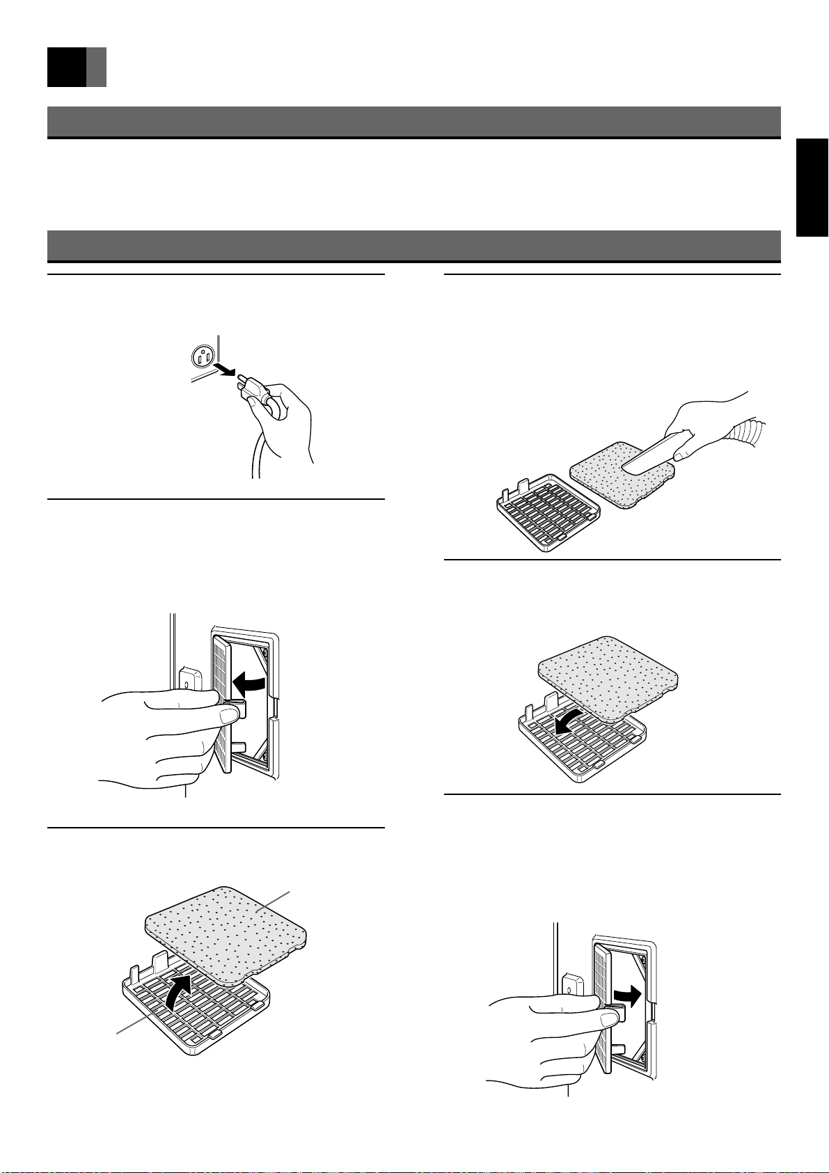
About the Air Filter
• If the air filter becomes blocked, the temperature inside the projector rises and the lamp fails to light, etc. Clean the air filter
about once every 6 months. Cleaning will be required more frequently if used in a particularly dusty environment.
• When the air filter becomes hard to clean, it is ready to be changed. Purchase a new air filter. (One filter is supplied with the
projector.)
Cleaning the Air Filter
EnglishFrançaisDeutschEspañol
Unplug the power cable from
1
the socket.
Remove the filter holder from
2
the projector.
Remove the filter holder from the bottom of the
projector.
Clean the air filter.
4
Use a vacuum cleaner to suck the dust from both
sides of the filter. If the filter is very dirty, wash in
cold or lukewarm water containing a neutral detergent
and dry away from direct sunlight.
Fit the air filter.
5
Fit the air filter back in the filter holder.
Detach the air filter.
3
Filter holder
Air filter
Fit the filter holder in the projec-
6
tor
Insert the catch on the filter holder in the bottom of
the projector and press until it clicks into place.
Take care not to
break the clasp on
the filter holder.
En-33
Page 34
Maintenance and Care (continued)
Care of the cabinet
Wipe lightly with a soft, dry cloth. If the cabinet is very dirty, wipe with a cloth that has been soaked in neutral detergent diluted
with water and wrung out well. Finish with a dry cloth.
Care of the lens
Clean the lens with a commercially available blower or cleaning paper. Use of tissues, etc. may damage the lens. As the surface of
the lens is easily damaged, do not rub or hit with anything hard.
Changing the Lamp
• When the lamp reaches the end of its service life, the image becomes dark and the colors lose their vividness. When this happens,
change the lamp unit.
• When the "Approaching Recommended Lamp Life!" message appears, change the lamp unit.
• A spare air filter is supplied with the lamp unit (optional). Change the air filter after changing the lamp unit.
• After removing the old lamp unit, handle with care to avoid breakage. Dispose of as industrial waste.
• Be sure to initialize the lamp timer after changing the lamp unit.
W ARNING
• Do not remove any screws other than those specified ( mark).
The high voltage and high temperature inside the projector may lead to electric shock or burns if touched.
• When changing the lamp unit, be sure to replace with a new lamp unit. Use of a used or second-hand lamp unit may lead to
breakage or failure of the lamp.
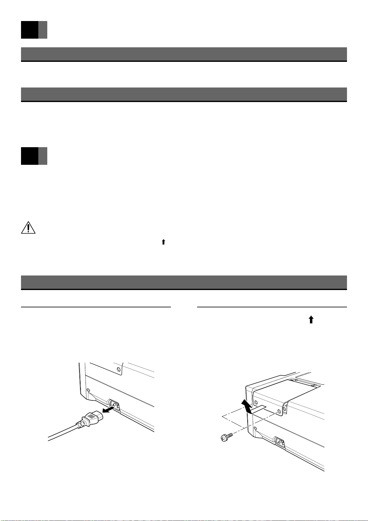
Changing the Lamp
Allow the lamp to cool for 1 hour after switching off the power before changing.
Press the POWER button and
1
remove the power connector
from the power terminal.
Remove the 2 screws ( mark)
2
and remove the lamp cover from
the projector.
For safety reasons, the safety devices are enabled
when changing the lamp to shut off the power.
En-34
Remove power connector
Page 35
Changing the Lamp
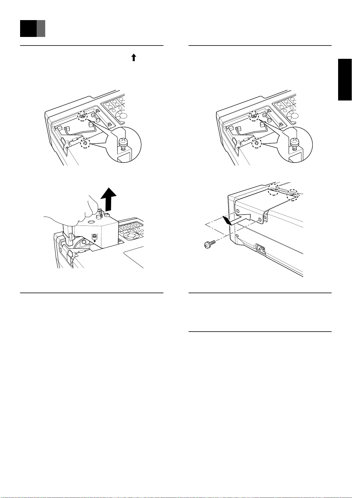
Loosen the two screws ( mark)
3
and lift out the lamp unit.
Replace the lamp unit and lamp
5
cover following the disassembly
procedures in reverse order.
EnglishFrançaisDeutschEspañol
Change the lamp unit.
4
Do not touch the glass inside the unit.
Dirt or fingermarks on the glass may reduce the
brightness of the lamp.
Insert the power connector into
6
the power terminal.
Press the POWER button.
7
The all monitors flash for a few seconds.
The lamp timer is initialized to [0 hours].
En-35
Page 36
Troubleshooting
Symptom Cause
No image or sound Power cable not plugged in properly. 20
Wires not connected correctly. 17 – 19
Incorrect setting of input selector. 22
Brightness adjustment is set on minus (–). 27
Incorrect arrangement of pins on cable used. 38
No sound without image input. Input image signal. 17 – 19
Incorrect PC image output signal.
Check PC settings. –
Mute mode is enabled. 23
Colors are pale. Color depth and tint not adjusted properly. 27
Tints are poor.
No color Video input mode for function adjustment not set on [AUTO]. 31
Image is blurred. Projection distance exceeds focus range. 15
Lens focus is not correctly adjusted. 22
Wireless remote control Wireless remote control unit light receiver on projector is 13
unit does not function. obstructed (Front and rear).
Batteries in wireless remote control unit have reached end of 13
service life.
Wireless remote control unit light receiver is subject to strong light. 10
Reference Page
The images cannot be Check the PC recommended timing. –
synchronized. PC display mode is on simultaneous display mode. 36
PC Output Signal
The projector has been designed with the RGB signals listed on page 39 in mind. Depending on your PC, the RGB signals output
may be different from the design values. In particular, when the internal LCD panel of the notebook PC and external CRT are set on
simultaneous display, the RGB signal output may be outside the compatible range. In this case, it may not be possible to display the
image normally. Set the PC to external CRT display mode.
En-36
Page 37
Specifications
Name LCD projector
Model LPF-7200, LPF-7200E
Type 3-plate LCD type
LCD size 1.3 inch
LCD drive system P-Si TFT active matrix
No. of pixels 2,359,296 (1024 x 768 pixels x 3)
Lens Electric powered zoom lens F=1.8 – 2.15 f=48.4 – 62.9mm
Lamp 250W NSH lamp
Projected picture size 30 inch – 300 inch
Projection distance 0.7m – 17.6m
Optical axis shift –10.8° – +10.8°
Picture aspect ratio 4 : 3
Projection format Left/right/up/down with reverse display setting
Rated voltage AC 100V
Rated frequency 50/60Hz
Power consumption 450W [Approx. 11W on standby]
Working temperature range 5°C – 40°C
Storage temperature –15°C – 60°C
EnglishFrançaisDeutschEspañol
Input/Output Input Video : RCA pin x 1
terminals S image : S terminal x 1
Digital RGB : DVI-D terminal x 1
Analog RGB : 15-pin D-sub terminal x 2
Analog RGB/Component
: BNC x 5
Sound : RCA pin (R/L) x 1
: 3.5ø mini stereo jack x 3
Mouse : 8-pin mini DIN terminal x 1 (female connector)
: USB terminal x 1
Wired remote : 3.5ø mini jack x 1
RS232C (for service personnel)
: 9-pin D-sub terminal x 1
Output Analog RGB : 15-pin D-sub terminal x 1
Sound : 3.5ø mini stereo jack x 1
Speaker 3W x 2 (stereo)
Outside dimensions 15.0cm (Height) x 27.9cm (Width) x 40.1cm (Depth)
Mass Approx. 7.5kg
Accessories Wireless remote control unit x 1, Size AA battery x 2, Air filter x 1,
RGB cable x 1, AV cable x 1, PS/2 mouse connection cable x 1,
Power cable x 1, Lens cap x 1, Instruction Manual (this manual) x 1
• The specifications and external appearance may be altered for improvement purposes.
• Be sure to connect the earth of the power plug before use.
En-37
Page 38
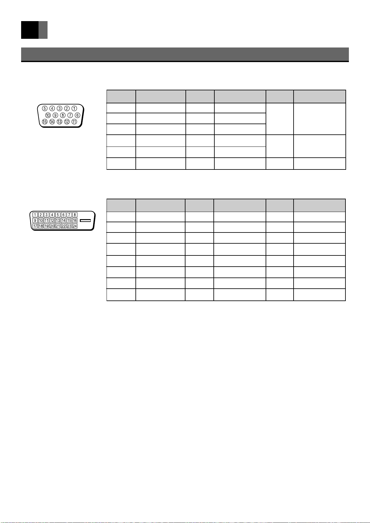
Specifications (continued)
RGB Input Terminal
HD-15 (mini D-sub)
DVI-D
Pin No. Signal Pin No. Signal Pin No. Signal
1 Red 7 Green earth
2 Green 8 Blue earth 13
3 Blue 9 N/C
4 N/C 10 Earth
5 N/C 11 N/C
6 Red earth 12 N/C 15 N/C
Pin No. Signal Pin No. Signal Pin No. Signal
1 T.M.D.S. Data2– 9 T.M.D.S. Data1– 17 T.M.D.S. Data0–
2 T.M.D.S. Data2+ 10 T.M.D.S. Data1+ 18 T.M.D.S. Data0+
3 T.M.D.S. Data2 Shield 11 T.M.D.S. Data1 Shield 19 T.M.D.S. Data0 Shield
4 N/C 12 N/C 20 N/C
5 N/C 13 N/C 21 N/C
6 DDC Clock 14 +5V Power 22 T.M.D.S. Clock Shield
14
Horizontal synchro-
nized signal /
component (TTL)
V ertical synchronized
signal (TTL)
7 DDC Data 15 Ground (for +5V) 23 T.M.D.S. Clock+
8 No Connect 16 Hot Plug Detect 24 T.M.D.S. Clock–
En-38
Page 39
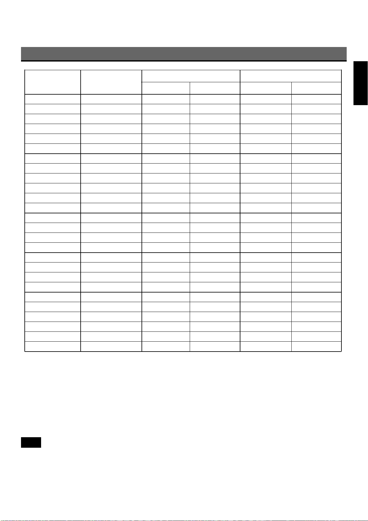
Table of RGB Compatible Frequencies
Resolution
PC
PCAT VGAEGA 640 350 31.5 70.0
PCAT VGA 640 400 31.5 70.0
PCAT VGA 640 480 31.5 59.9
PCAT VGA 640 480 37.5 75.0
PCAT VGA 640 480 37.9 72.8
PCAT VGA 640 480 42.3 85.0
PCAT SVGA 800 600 35.2 56.3
PCAT SVGA 800 600 37.9 60.3
PCAT SVGA 800 600 48.1 72.2
PCAT SVGA 800 600 46.9 75.0
PCAT SVGA 800 600 52.5 76.0
PCAT SVGA 800 600 53.7 85.0
PCAT XGA 1024 768 48.4 60.0
PCAT XGA 1024 768 56.5 70.0
PCAT XGA 1024 768 60.0 75.0
PCAT XGA 1024 768 68.7 85.0
PCAT SXGA* 1152 864 67.5 75.0
PCAT SXGA* 1280 960 60.0 60.0
PCAT SXGA* 1280 1024 64.0 60.0
PCAT SXGA* 1280 1024 80.0 75.0
MAC 13-inch 640 480 35.0 66.7
MAC 16-inch 832 624 49.7 74.5
MAC 16-inch 832 624 49.1 75.1
MAC 19-inch 1024 768 60.2 74.9
MAC 19-inch 1024 768 48.2 59.3
MAC 21-inch* 1152 870 68.7 75.1
Picture mode
Horizontal (dot) Vertical (line) Horizontal (kHz) Vertical (Hz)
Frequency
EnglishFrançaisDeutschEspañol
• * indicates simple display. It is not suitable for DIGITAL RGB input.
• No image appears even if the resolution and frequency mentioned above are the same.
• PC display mode
When an image signal is input from a PC, the projector automatically selects the mode (resolution and frequency) and projects
the picture according to that mode.
The projector fundamentally conforms to VESA (Video Electronics Standards Association) standards, but depending on the type
of PC, a non-VESA signal may be output. In such cases, the projected image will not be correctly displayed, the overall picture
will be blue in color, and the [No Signal] message will be displayed on the screen. In this case, reset the image signal from the
PC to another compatible mode. For details, refer to the above table and the instruction manual for the PC.
Note
• All names of companies and products contained in this manual are trademarks or registered trademarks of the respective
companies.
• VGA is a registered trademark of IBM.
• Macintosh is a registered trademark of Apple Computer Inc.
En-39
Page 40

En-40
 Loading...