

Page 1

LPe1150 HBA
Installation Manual
Page 2

Copyright© 2005 Emulex Corporation. All rights reserved worldwide. No part of this document may be reproduced
by any means nor translated to any electronic medium without the written consent of Emulex Corporation.
Information furnished by Emulex Corporation is believed to be accurate and reliable. However, no responsibility is
assumed by Emulex Corporation for its use; or for any infringements of patents or other rights of third parties which
may result from its use. No licens e is grant ed by impl ication or oth erwise under any pa tent or paten t right s of Em ulex
Corporation.
Emulex and LightPulse are registered trademarks, and AutoPilot Installer, AutoPilot Manager, BlockGuard,
FibreSpy , HBAnyware, InSpeed, MultiPulse, SLI and SBOD are trademarks, of Emulex Corpo ration. All other b rand
or product names referenced herein are trademarks or registered trademarks of their respective companies or
organizations.
Emulex provides this manual "as i s " wi thout any warranty of any kind, either express ed o r i mp lie d , i nclud i ng but n ot
limited to the implied warranties of merchantability or fitness for a particular purpose. Emulex Co rpo ration may
make improvements and ch ang es t o t he pr odu ct des cribed in this manual at any tim e and w ith out an y n ot ice. Emulex
Corporation assumes no responsibility for its use, nor for any infringements of patents or other rights of third parties
that may result. Periodic changes are made to information contained herein; althou gh thes e chang e s will be
incorporated into new editions of this manual, Emulex Corporation disclaims any undertaking to give notice of such
changes.
LPe1150 Hardware Installation Manual Page ii
Page 3

Table of Contents
Introduction...................................................................................................................................................1
Major Features ................................................................................................................................1
Compatibility....................................................................................................................................2
Prerequisites....................................................................................................................................2
Installing the Host Bus Adapter ....... ...... ....................................... ...... ....... ...... ....... ...... ....... .........................2
Attaching Media............................................................................................................................................4
Applying Power.............................................................................................................................................5
Viewing the LEDs ............................................... ....... ...... ...... ....... ...... ....... ...... ....... ...... ...... .............5
POST Conditions and Results.........................................................................................................5
References ...................................................................................................................................................7
Specifications ..................................................................................................................................7
FCC and Regulatory Notices...........................................................................................................8
Declaration of Conformity................................................................................................................9
Laser Safety Notice .......................................................................................................................11
LPe1150 Hardware Installation Manual Page iii
Page 4

Introduction
The Emulex® LPe1150 host bus adapter (HBA) is a single-channel, 4.25 gigabit per second (Gb/s), Fibre
Channel (FC) Peripheral Component Interconnect Expre ss (PCIe ) HBA . The cor e tec hnolo gy of this
HBA is Emulex’s eighth generation FC controller. The controller incorporates a multifunction native PCIe
core that is compliant to the PCIe Base Specification 1.0a and PCI Express CEM Specification 1.0a. The
HBA supports packet transfers up to 2048 bytes on the PCIe link with su ppor t for x1 or x4 lane
negotiation. The supported physical PCIe connec tor is x 4 or higher ( x8 or x16 ). The ful ly feature d FC
port is compliant to various American National Standards Institute (ANSI) FC standards. The product is
targeted at FC storage networking environments that require the highes t degrees of robustnes s,
performance and ease of management.
Major Features
• PCIe device with with one FC port
• Auto-negotiation between 1-Gb, 2-Gb or 4-Gb link attachments
• High performance FC HBA with the PCIe to FC controll er with one i ntern al proces so r
• Full support for all FC topologies i ncl uding p oint-to-p oint, ar bitrated l oop and fa bric
• Full support for FC service class 2 and 3
• Maximum FC throughput achieved via full duple x hardwar e sup port
• End-to-end data path-parity and cyclical redundancy check (CRC) protection, including internal
data path random-access memory (RAM)
• Architectural support for multiple upper lay er protoc ols
• State-of-the-art circuitry:
• Al l PCIe an d FC functio nali ty contained within a single, custom, high-density, fully integrated FC controller
• Inter nal A RM 1136J-S processor with instruction and data cache for each p ort
• Inter nal serializer deserializer (SerDes) 1-Gb/2-Gb/4-Gb core for FC and 2.5-Gb cores
for PCIe
• Complies with the PCIe base and CEM 1.0a speci fic ations:
• x1 o r x4 lane l ink inter face (auto-neg otiated wi th sy stem ) at 2.5-Gb/s
• Supp orts VC0 (1 Virtual Channel) and T C0 ( 1 Traffic Class)
• Config uration /IO / Memor y read/write, c ompl etion an d message
• Supp orts 64-bit addres sing
• ECRC for all transmitted PCIe data packets
• Link CRC on all PCIe packe ts and message info rmation
• Supp orts large payload size- 20 48 byte s for rea d/write
• Supp orts large read re quest size- 4 096 by tes
• Internal high-speed static RAM (SRAM)
• Error correcting code (ECC) protection of local mem ory, including single-bit correction and
double-bit protection
• The LPe1150 HBA provides an embedded short wave optical (LC) connection with link
diagnostics capability.
LPe1150 Hardware Installation Manual Page 1
Page 5
• Host interface via Emulex standard drivers o r through c usto m dri vers wr itten to the Em ulex
Service Level Interface (SLI-2) that is compatible with the man y ex isti ng Em ulex dri vers for
products such as LP8000, LP9002L, LP9802, LP1 0000 HBAs
• Comprehensive array of operating sy stem (OS) drivers:
• Emulex standard device drivers for Windows 2000 Server, Windows Server 2003, Novell
NetWare and Linux
• Som e drivers s uppor t both SC SI and IP protocol s
• Supp ort for remote and fabri c boot functi onali ty
• On-board context management by the firmware:
• Up to 510 F C port log ins
• Up to 1023 conc ur rent exch anges
• I/O m ultip lexi ng down to the FC frame lev el
• Data buffers capable of supporting 16 buffer-to-buffer (BB) credits for short-wave applications
• Link management and recovery handled by the firmwar e
• On-board diagnostic capability acces si ble v ia optional conne ction
• Parts and construction compliant to the Eu ropean Union Directive of Restriction of Hazardou s
Substances (RoHS)
Compatibility
Table 1. Software and Hardware Environments
Software Environments Windows 2000 Server, Windows Serv er 200 3, Novell
NetWare and Linux
Hardware Environments PCI-Express 1.0a comp liant syst ems
Prerequisites
• PCI-Express 1.0a compliant system s:x 1 or x4 la ne transfer lin k in terfac e at 2.5-G b/s per lan e
• 3.3-V power from PCIe slot is required for ope ration
Installing the Host Bus Adapter
To install the HBA:
1. Each HBA is shipped with a unique 64-bi t identi fier cal led the IEEE addr ess. T he FC industry
uses a World Wide Name (WWN) derived from the IEEE address, and this number is needed for
FC connectivity. The IEEE address is used when configuring your system . The ser ial n umber is
used when communicating with Emulex. A ll nu mber s are cl ear ly m arked on the boar d. We
recommend that you record these numbers befor e installation.
2. Turn off and unplug the computer.
3. Remove the computer case.
Note: For best I/O performance, pla ce the ad apt er into an empt y PC Ie x4 or hig her slot.
PCIe slots are shorter t han standa rd PCI 64 -b it slots. Do not at te mpt to pl ug the
adapter into a standard PC I slot .
LPe1150 Hardware Installation Manual Page 2
Page 6

4. Remove the blank panel from an empty PCIe bus slot. Follow steps 5–8 to change the bracket if
they are different sizes. Otherwise, skip to step 9.
Note: The HBA comes with a standard PCI br ack et install ed . A low -p rofi le br ac ket is
included in the box wit h th e HBA. The lo w-p ro file mo unt in g bracket is shorter than
the standard bracket; approximately 3.11 in. (7.9 cm) compared to 4.75 in. (12.06 cm)
long.
5. Remove the mounting bracket screws from the top of the HBA.
Figure 1: Removing the Bracket
6. Remove the bracket and store it for future use.
7. Align the new mounting bracket tabs with the holes in the HBA.
Note: Be careful not to push the bra cket past th e tr an sceive r ho usi ng's groun din g tabs.
Make sure the light emit ti ng diod es (LE Ds ) are pr op erly al ig ned with t he ho le s
in the bracket.
8. Replace the screws that attach the HBA to the bracket.
9. Insert the HBA into the empty x4 or higher PCIe bus slot. Press firmly until the adapter is seated.
10. Secure the HBA's mounting bracket to the case with the panel screw or clip.
11. Replace the computer case and tighten case screws.
The HBA is now installed in the PC and is ready for medi a attachment.
LPe1150 Hardware Installation Manual Page 3
Page 7
Attaching Media
Note: The HBA will not allow norma l da ta transmi ssi on on an optic al li nk un les s it is
connected to anothe r si mila r or compat ib le laser pr oduct (th at is , mult imod e to
multimode.)
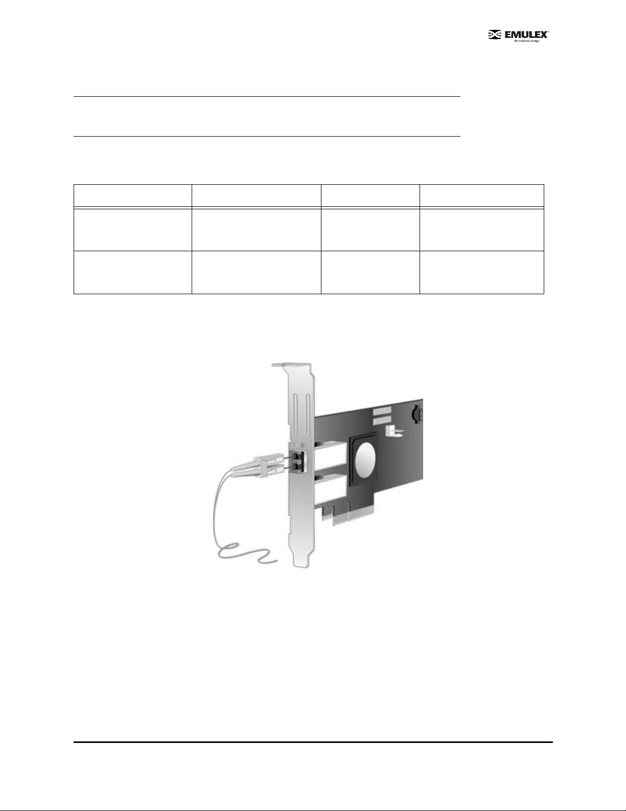
Use multimode fiber optic cable, with short-wave l ase rs , that adheres to the foll owing spec ific ations :
Table 2: Media Specifications
Fiber Optic Cable Maximum Length Minimum Length Connector
62.5/125 µm (multimode)
200 MHz*km bandwidth
cable
50/125
µm (multimode)
500 MHz*km bandwidth
cable
300 meters at 1.0625 Gb/s
150 meters at 2.125 Gb/s
70 meters at 4.25 Gb/s
500 meters at 1.0625 Gb/s
300 meters at 2.125 Gb/s
150 meters at 4.25 Gb/s
.5 meters LC
.5 meters LC
To attach media to the HBA:
1. Connect the fiber optic cable to the LC connectors on the HBA.
Figure 2: Connecting Fiber Optic Cable
2. Connect the other end of the cable to the Fibre Channel device.
After the media is connected to the HBA, you are ready to apply power to the computer.
LPe1150 Hardware Installation Manual Page 4
Page 8

Applying Power
To apply power:
1. Verify that the HBA is securely installed in th e comp uter.
2. Verify that the correct media is attached.
3. Plug in and turn on the computer.
4. Observe LEDs for Power On Self Test (POST) results.
Viewing the LEDs
Green and yellow LEDs can be seen through openings in th e HBA's mounting br ack et. Green i ndicates
firmware operation and yellow signifies port activ ity. Each port has a corresponding set of green and
yellow LEDs.
Figure 3: LEDs
POST Conditions and Results
POST conditions and results are summa rized i n the foll owing table:
Note: For the Link Rate conditions, there is a 1 Hz pause when the LED is off between each
group of fast blinks (1, 2 or 3) . You should observe the LED sequence for seve r al
seconds to ensure that the pause is cor rect ly iden ti fi ed.
Table 3: POST Conditions and Results
Yellow LED Green LED State
Off Off Wake-up failure (Dead board)
On Off POST failure (Dead bo ar d)
Slow Blink Off Wake-up failure monitor
Fast Blink Off POST failure
Flashing Off POST processing in progress
Off On Failure while funct io ning
On On Failure while functio ni ng
1 Fast Blink On 1Gb Link rate -Nor mal, li nk up
2 Fast Blinks On 2Gb Link rate -Normal , li nk up
3 Fast Blinks On 4Gb Link rate -Normal , li nk up
Off Slow Blink Normal -link down or not s tarted
LPe1150 Hardware Installation Manual Page 5
Page 9

Table 3: POST Conditions and Results (Continued)
Yellow LED Green LED State
Slow Blink Slow Blink Off-line for dow nlo ad
Fast Blink Slow Blink Restricted off-l ine mode (Waiting fo r re start)
Flashing Slow Blink Restricted off-line mode (Test active)
LPe1150 Hardware Installation Manual Page 6
Page 10
References
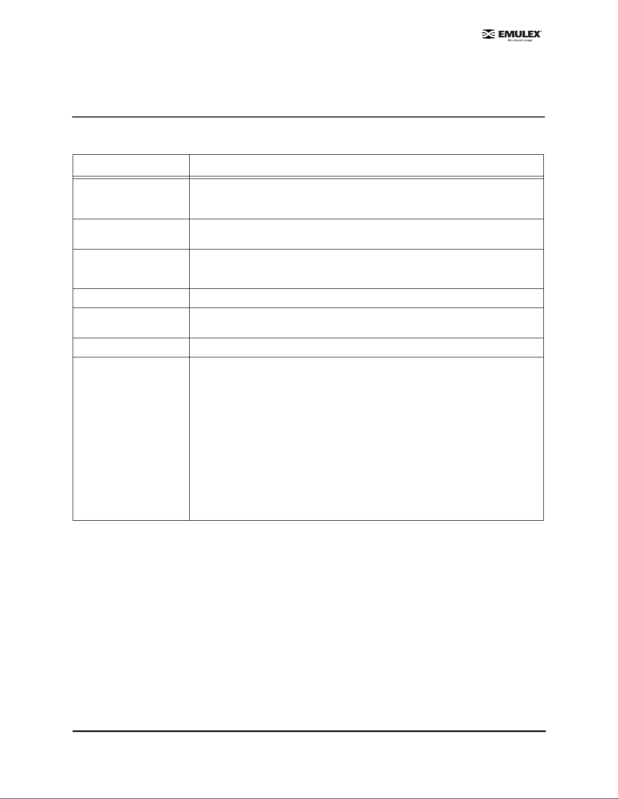
Specifications
T able 4: LPe1150 Specifications
Parameter Range
Media Interface The controller in te rfaces to the physical medi a th ro ugh an FC- 0 Med ia I nt erfa ce
(FC-PI compliant tr an sceiv er) , an d then co nne cts thr ough du al opti cal fib er LC
connectors.
Physical Di mensions Low-profile MD2 form fac to r, 6.600 inches by 2.53 6 inches, and acco mmodat es
both the full-heigh t an d low -pr of il e brack et .
Power Requir eme nts
Airflow 100 lf/min (minimum)
Temperature 32° to 131° F (0° to 55° C), Operating
Humidity 5% to 95% non-conden sin g
Agency Approvals for
LPe1150
In a PCIe x4 slot:
• 5.0 watts (typical) @ +3.3 VDC
• 7.1 watts (maximum) @ +3.3 VDC
-40° to 158° F (-40° to 70° C), Storage
Class 1 Laser Product per DHHS 21CFR (J) & EN60825-1
UL recognized to UL6095 0- 1: 2003
CUR recognized to CSA 22.2, No. 60950-1-03
Baurt-certified by TUV to 60950-1
FCC Rules, Part 15, Class A
Industry Canada, ICES-003, Class A
EMC Directiv es 89/336/EEC and 2004/108/ EC (CE Mark)
EN55022, Class A
EN55024
Australian EMC Framework (C-Tick Mark)
AS/NZS CISPR22:20 02 Cla ss A
Japan VCCI, Class A
Taiwan BSMI, Class A
Korea MIC, Class A
LPe1150 Hardware Installation Manual Page 7
Page 11

FCC and Regulatory Notices
LPe1150 HBA Models
This device complies with Part 15 of the FCC Rules. Operation is subject to the following two conditions:
(1) This device may not cause harmful i nterf erence, and (2) this devi ce m ust ac cep t any i nterfe rence
received, including interference that m ay c ause undes ire d operation.
Responsible Party:
Paul Folino, Chief Ex ecut iv e Officer
Emulex Corporation (714) 662-5600
3333 Susan St. Costa Mesa, CA. 92626 US A
Note:This equipment has been tested and found to com ply wi th the li mits for a Class A di gital devic e,
pursuant to part 15 of the FCC Rules. These limits are designed to provide reasonable protection
against harmful interference when the equipment i s operated in a commer cial env ir onmen t. This
equipment generates, uses, and can radiate radio fr equenc y en ergy and, i f not ins talled and us ed in
accordance with the instruction man ual, may cause harmful interference to radio communi cati ons.
Operation of this equipment in a residential area is likely to cause harmful interference in which case the
user will be required to correct the interference at hi s own expens e. T he reader is c autio ned that
changes or modifications made to the equipment not expr es sly approve d by Em ule x co uld void the
user's authority to operate this equipment. T he above statement appl ies to pro ducts marketed in the
USA.
This class A digital apparatus meets all requirements of the Industry Canada (IC) Interference - Causing
Equipment Standard (ICES-003).
Cet appareil numerique de la Classe A respecte tout es le s exigenc es du re glemen t sur le materiel
brouilleur du Canada. This statement applies to products marketed in Cana da.
Notice for Japan and Translations (VCCI)
Product Label
This is a Class A product. In a domestic environment this product may cause radio interference in which
case the user may be required to take adequate measu res. VCCI—A
Manual Notice
Translation:
This is a Class A product based on the standard of the Voluntary Control Council for Interference by
Information Technology Equipment (VCCI). If this equipment is used in a domestic envi ronment, r adio
disturbance may arise. When suc h trouble o cc urs, the us er m ay be requi red to take correc tive actio ns.
LPe1150 Hardware Installation Manual Page 8
Page 12

Notice for Taiwan and Translations (BSMI)
Translation:
This equipment is a Class A ITE, and oper atio n of this equip ment in a res idential area is likely to cause
harmful interference, in which cas e use rs will b e req uir ed to c orrect the interference at their own
expense.
Notice for South Korea and Translations (MIC)
Translation:
Class A Equipment: Please note that this equipme nt has b een approv ed for business pur poses with
regards to electromagnetic interference. If purchased in error for use in a residential area, you may wish
to exchange the equipment where you purchased i t.
Declaration of Conformity
LPe1150 HBA
This equipment complies with CIS PR22/EN 55022 Class A.
WARNING: This is a class A product. In a domestic environmen t, thi s pr odu ct may c aus e radio
interference req uirin g th e use r to take ade qu at e meas ur es.
Note: Changes or modifications not expr es sly appr ove d by Emule x Co rpor at ion cou ld void
the user's authority to oper ate t his equi pme nt.
LPe1150 Hardware Installation Manual Page 9
Page 13

LPe1150 Hardware Installation Manual Page 10
Page 14

Laser Safety Notice
This laser safety information contains ce rtificati on and p rodu ct in forma tion c overing las er produc ts
known as optical small form fact or trans ceiver s in corpor ated i n Emul ex L ightPulse host adapters. The
small form factor transceiver is the primary cable connection mechanism for any optical port on the host
adapter. This data is not intended to be a replacement for any safety regulations and standards; relevant
safety documents should always be consul ted if necess ar y. Contact Emulex Corporation with any
questions or concerns about laser safety.
Certification and Classification
The LPe11000, LPe11002 and LPe1150 host adapters may contain a laser product known as a small
form factor transceiver. This transceiver provides the physical connec tion to the optic al cable, an d its
LC-style connector extends through the mounting bracket. In turn, the host adapter can be inserted into
any host system's appropriate PCI/PCI-X expansion slot.
In the United States, all optical small form factor transceivers sold by Emulex are ce rtifi ed as Class 1
laser products that conform to the requirements contained in the Department of Heal th and Huma n
Services (DHHS) regulation 21 CFR subchapter J. The certification is indicated by a label located on the
optical small form factor transceiver.
In Europe, all optical small form factor tr anscei vers s old b y Em ulex are certified as Class 1 laser
component assemblies that conform to the requi rements contained in the CE NELE C (Europ ean
Committee for Electrotechnical Standardization) standard EN60825-1:1994 (including amendment 11)
and EN60825-2:1994. Small form factor transc eiv ers ar e certifi ed by a recogni zed E uro pean test ing
agency and have appropriate markings on the assembly. The DHHS conformity label and European
conformity mark will not be visible exter nall y once the opti cal small form factor transceiver is connected
to or inserted in the host adapter and the adapter is installed into a system.
Labeling Requirements
No caution or danger labels are required for use of the small form factor transceiver since they are Class
1 laser component assembly. In the U.S., the only laser safety label required is the DHHS certification
label that already appears on the small form factor tr ansceiv er. In Europe, the EN60825-1/EN60825-2
standards require that the system-level product has a Class 1 in forma tion l abel pe rman ently attached
and clearly visible whenever access to the GLM, GBIC, 1x9 and small form factor transceiver optical port
is possible. Each Class 1 product sh all have affixed an explanatory label bearing the word s:
LPe1150 Hardware Installation Manual Page 11
Page 15

Alternatively, at the discretion of the manufacturer, the same statement may be included in user
information. If a label is used, an example of the IEC Cl ass 1 infor mati on labe l that i s su itable for most
European countries is shown below. The label consists of black printing on a white backgro und.
Languages represented on this label are En glis h, Germ an, F innish and Frenc h, and they represent the
minimum set for acceptance of a Class 1 product in most E uropean c ountr ies.
Product Information
Small Form Factor Transceiver
The small form factor transceiver is an integrated duplex data link for bi-directional communications over
multimode or single mode optical fiber. Each small form factor transceiver cons is ts of a transmitter and
receiver optical subassembly. The transmitter subassembly contains a semicon ductor las er emitti ng in
the wavelength range of 770 to 860 nanometers for shortwave length small form factor transceivers and
1270 to 1355 nanometers for long wavelength small form factor tran sc eivers . For non -OFC link s, the
optical power from the laser transmitter is c ontrolled and maintained at a lower power level. The power
emitted from either an open fiber or open laser transmi tter is gua rante ed to be below the Cla ss 1 lim it.
Class 1 laser products are not considered haza rdou s. No us er mainten ance, s er vice oper atio ns or
adjustments can be performed the small form factor tran sc eiver.
Usage Restrictions
Failure to comply with these usage restrictions may result in incorrect operation of the system and could
possible lead to points of access that may emit laser radiation levels above the Class 1 limits established
in the U. S. by the DHHS and within Europe by EN60825-1/EN60825-2.
Short wavelength and long wavelength small form factor transceivers allow normal data transmission on
the optical link when they are connected to another compatible laser product. Short wavelength and long
wavelength small form factor transceiv ers embe dded in Emul ex ho st adap ter are non -O FC. For nonOFC links, a compatible laser device mu st be no n-OF C and ce rtified as a Clas s 1 l aser pr oduc t.
Any system level product that incorporates the small form factor transceivers must provide power supply
protection that guarantees a voltage of 5.0 volts or less at the smal l form factor transceivers. The
functional power supply range of the small for m fac tor trans cei vers produc t is spec ified as 3.135 to
3.465V typically. Operation outside of this range may degrade the performance and lifetime of the
transceiver. The transceiver will remain operational with laser emis si ons b elow Cla ss 1 lim its provi ded
the power supply level at the adapter remains at or below 5.0 volts. If the power supply level rises above
5.0 volts, the small form factor transceiver cannot be guaranteed to operate correctly and could result in
laser emissions that m a y exceed Class 1 limits.
System Level Certification
All host adapters containing embedded small form factor tra nsc eivers are cer tifi ed as Cl ass 1 las er
products within the U.S. and Class 1 laser com ponent as sem blie s outside of th e U.S. Manu facturer s of
products properly incorporating the small form factor transceiver do not need to recertify their product for
laser safety. The procedure for full system certification is therefore identical to that used for any o ther
electronic system. When applying for sy stem l evel cert ificati on to ele ctronic standards such as IEC950,
the regulatory engineers may want to see the DHHS and European conformity labeling on the small form
LPe1150 Hardware Installation Manual Page 12
Page 16

factor transceiver, and the system level documentation and labeling. Copies of the cer tific ate of
conformity for any small form factor trans cei ver sol d by E mulex c an be obtained upo n req uest from
Emulex Corporation, Costa Mesa.
LPe1150 Hardware Installation Manual Page 13
 Loading...