

Page 1

Copyright
Copyright
Fujitsu Limited has made every effort to ensure
the accuracy and completeness of this document.
However, as ongoing development efforts are
continually improving the capabilities of our
products, we cannot guarantee the accuracy of
the contents of this document. We disclaim
liability for errors, omissions or future changes.
LifeBook is a trademark of Fujitsu Limited.
Microsoft, Windows, MS , MS-DOS and Windows
NT are registered trademarks of the Microsoft
Corporation of the United States in the United
States and other countries.
Phoenix is a registered trademark of Phoenix
Technologies Corporation of the United States.
Copyright© 1981-1999 Microsoft Corporation, All
rights reserved.
Copyright© 1999 Phoenix Technologies, Ltd., All
rights reserved.
Other product names are trademarks or
registered trademarks of their respective
companies.
© Copyright 2006 Fujitsu Limited. All rights
reserved. No part of this publication may be
copied, reproduced or translated, without the
prior written consent of Fujitsu Limited. No part
of this publication may be stored or transmitted
in any electronic form without the written consent
of Fujitsu Limited.
Operations are subject to the following two
conditions:
(1) This device may not be allowed to cause
harmful interference.
(2) This device must accept any interference
received, including interference that may
cause undesired operation.
Website: www.pc-ap.fujitsu.com
DECLARATION OF CONFORMITY
according to FCC Part 15
This device complies with Part 15 of the FCC rules. Operations are subject to the following two conditions:
(1) This device must not be allowed to cause harmful interference. (2) This device must accept any
interference received, including interference that may cause undesired operation.
i
Page 2

IMPORTANT SAFETY
INSTRUCTIONS
1. Read these instructions carefully. Sa ve these
instructions for future reference.
2. Follow all warnings and instructions marked
on the product.
3. Unplug this product from the wall outlet
before cleaning. Do not use liquid cleaners
or aerosol cleaners. Use a damp cloth for
cleaning.
4. Do not use this product near water.
5. Do not place this product on an unstable cart,
stand or table. The product may f all, causing
serious damage to the product.
6. Slots and openings in the cabinet and the
back or bottom are provided for ventilation;
to ensure reliable operation of the product
and to protect it from overheating, these
openings must not be blocked or covered.
The openings should never be blocked by
placing the product on a bed, sofa, rug or
other similar surface. This product should
never be placed near or over a radiator or
heat register or in a built-in installation unless
proper ventilation is provided.
7. This product should be operated from the
type of power indicated on the marking label.
If you are not sure of the type of power
available , consult your dealer or local pow er
company.
8. Do not allow anything to rest on the power
cord. Do not locate this product where
persons will walk on the cord.
9. If an extension cord is used with this product,
make sure that the total ampere rating of the
equipment plugged into the extension cord
does not exceed the extension cord ampere
rating. Also, make sure that the total rating
of all products plugged into the wall outlet
does not exceed 15 amperes.
10. Never push objects of any kind into this
product through cabinet slots as they may
touch dangerous voltage points that could
result in a fire or electric shock. Never spill
liquid of any kind on the product.
11. Do not attempt to service this product
yourself, as opening or removing co vers may
expose you to dangerous voltage points or
other risks. Refer all servicing to qualified
service personnel.
12. Unplug this product from the wall outlet and
refer servicing to qualified service personnel
under the following conditions:
a. When the power cord or plug is damaged
or frayed.
b. If liquid has been spilled into the product.
c. If the product has been exposed to rain or
water.
d. If the product does not operate normally
when the operating instructions are followed.
Adjust only those controls that are covered
by the operating instructions since improper
adjustment of other controls may result in
damage and will often require extensive
work by a qualified technician to restore the
product to normal condition.
e. If the product has been dropped or the
cabinet has been damaged.
f. If the product exhibits a distinct change in
performance, indicating a need for service.
ii
Page 3

13. CAUTION: When replacing the battery , be
sure to install it with the polarities in the
correct position. There is a danger of
explosion if the battery is replaced with
an incorrect type or is mistreated. Do not
recharge, disassemble or dispose of in
fire. Replace only with the same or
equivalent type recommended by the
manufacturer. Dispose of the used battery
according to the manufacturer’s
instructions.
14. Use only the proper type of power supply
cord set (provided in your accessories box)
for this unit. It should be a detachable type:
UL listed/CSA certified, BS1363, ASTA,
SS145 certified, rated 10A 250V minimum,
VDE approved or its equivalent. Maximum
length is 15 feet (4.6 meters).
Proper Disposal of Battery
Under federal, state or local law , it ma y be illegal
to dispose of batteries by putting them in the
rubbish bin or trash cans. Please take care of
our environment and dispose of batteries
properly. Check with your local government
authority for details regarding recycling or
disposing of unwanted batteries.
iii
Page 4

NOTE ON USE REQUIRED HIGH
SAFETY
This product is designed and manufactured for
general use, including general office use,
personal use, household use and ordinary
industrial use.
This product is not designed for or intended for
use under dangerous (fatal) conditions, unless
extreme safety precautions are implemented.
Do not use this product without implementing
high-level safety precautions.
Failure to f ollow this warning may result in death,
personal injury, se vere physical damage or other
loss, if used in or near any or more of the
following:
• nuclear reaction control system in a nuclear
facility
• automatic flight control system in an airplane
or other flight control system
• mass transport control system
• medical instruments for life support system
• missile launching control for weapon system
NOTE ON BACKUP DATA
Please make a backup of the Operating System,
any software programs, and created files (and
update regularly).
If you send this product to Fujitsu, or any of its
affiliates, suppliers, service providers or resellers
for repair, Fujitsu does not guarantee the data
integrity. It is your responsibility to back data up
beforehand.
Fujitsu does not assume any obligation for
compensation for damages, data integrity, or
restoration, etc., if your data is lost for any reason,
except as written in the warranty.
iv
Page 5

Copyright
AUSTRALIAN W ARNINGS
WARNING
FOR SAFETY REASONS, ONLY CONNECT
EQUIPMENT WITH A TELECOMMUNICATIONS COMPLIANCE LABEL. THIS INCLUDES
CUSTOMER EQUIPMENT PREVIOUSLY LABELLED PERMITTED OR CERTIFIED.
Connection of Non Certified/Approved
peripherals may result in the equipment
operating outside the Australian EMI
Standards.
Modems connected to the Australian
telecommunications network must be operated
in accordance with the Labelling Notice. This
modem has been specifically configured to
ensure compliance with the ACA Standards. Do
not adjust your modem or software outside the
values indicated below. To do so would result in
your modem being operated in a non-compliant
manner.
Call Attempts/Retries:
Applications software shall be configured so that
no more than 3 attempts are made to establish a
connection to a given number (Note: if the modem
can detect service tones, up to 10 attempts can
be made). If the call sequence is unsuccessful,
there shall be a delay of at least 30 minutes
before attempting to call the number again.
Failure to set the modem and any application
software used with the modem, to the values
shown above will result in the modem being
operated in a non-compliant manner.
Consequently, this would be in violation of the
Labelling Notice for this equipment and the
Telecommunications Act 1997 prescribes
penalties for the connection of non-compliant
equipment.
v
Page 6

NEW ZEALAND WARNINGS
The grant of a Telepermit for any item of terminal
equipment indicates only that Telecom has
accepted that the item complies with minimum
conditions for connection to its network. It
indicates no endorsement of the product by
T elecom, nor does it provide any sort of warranty.
Above all, it provides no assurance that any item
will work correctly in all respects with another
item of Telepermitted equipment of a different
make or model, nor does it imply that any product
is compatible with all of Telecom’s network
services.
This equipment is not capable under all operating
conditions of correct operation at the higher
speeds for which it is designed. 56 KBPS
connections are likely to be restricted to lower
bit rates when connected to some PSTN
implementations. Telecom will accept no
responsibility should difficulties arise in such
circumstances.
Immediately disconnect this equipment should it
become physically damaged, and arrange for its
disposal or repair.
This equipment shall not be used in any manner,
which could constitute a nuisance to other
Telecom customers.
This equipment shall not be set to make
automatic calls to the Telecom “111” Emergency
Service.
This device is equipped with pulse dialing while
the New Zealand standard is DTMF tone dialing.
There is no guarantee that Telecom lines will
always continue to support pulse dialing. It is
strongly recommended that pulse dialing is not
used.
Some parameters required for compliance with
Telecom’s Telepermit requirements are
dependent on the equipment (PC) associated
with this device. The associated equipment shall
be set to operate within the following limits for
compliance with Telecom’s Specifications:
For repeat calls to the same number.
There shall be no more than 10 call attempts
to the same number within any 30 minute
period for any single manual call initiation and
the equipment shall go on-hook for a period of
not less than 30 seconds between the end of
one attempt and the beginning of the next
attempt.
For Automatic calls to different numbers.
The equipment shall go on-hook for a period
of not less than 5 seconds between the end of
one attempt and the beginning of the next
attempt.
For Automatically answered Incoming
Calls.
Incoming calls shall be answered between 3
and 30 seconds from the start of the ringing.
For correct operation, the total of the RNs of all
devices connected to a single line at anytime
should not exceed 5. The RN of this Equipment
is 0.5.
WARNING:
CONNECTION OF NON CERTIFIED/
APPROVED PERIPHERALS MAY RESULT IN
THE EQUIPMENT OPERA TING OUTSIDE THE
NEW ZEALAND EMI STANDARDS.
vi
Page 7
Copyright
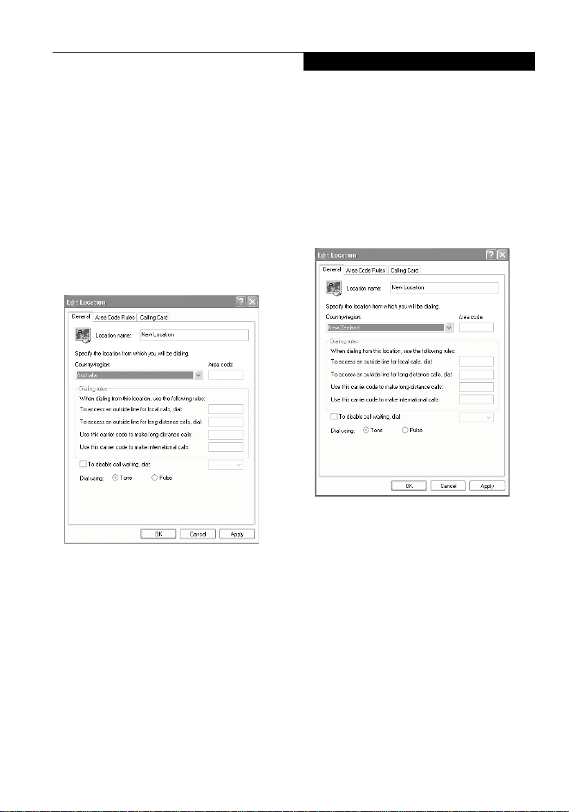
NOTE: Modem setting in Windows
XP
A. If you are located in Australia
1. Click Start select Control panel select
"Phone and Modem Options".
2. Double click New Location.
3. Choose "Australia" in Country/region pull
down menu bar.
4. Select Phone system as “Tone Dialing”.
5. Click OK and Apply.
B. If you are located in New Zealand
1. Click start select Control panel select
"Phone and Modem Options".
2. Double click New Location.
3. Choose "New Zealand" in Country/region
pull down menu bar.
4. Select Phone system as “Tone Dialing”.
5. Click OK and Apply.
NOTE:
The screens and illustrations shown in this
examples may slightly vary depending on the
operating environment that you have installed.
vii
Page 8

Fujitsu LifeBook® T Series Tablet PC
Table of Contents
1
PREFACE
About This Guide ...........................................3
2
GETTING TO KNOW YOUR
TABLET PC
Locating the Controls and Connectors
Top and Front Components............................9
Left-Side Panel Components ......................... 11
Right-Side Panel Components....................... 12
Rear Panel Components................................ 13
Bottom Components ......................................14
Status Indicator Panel
Power Indicator .............................................. 15
AC Adapter Indicator...................................... 15
Battery Charging/Level Indicators ..................15
Wireless LAN Access Indicator ......................16
Optical Drive Access Indicator .......................16
Hard Drive Access Indicator ..........................16
NumLk Indicator.............................................16
CapsLk Indicator ............................................ 16
ScrLk Indicator ............................................... 16
Security Indicator ...........................................16
Display Panel
Opening the Display Panel.............................17
Using the System as a Tablet.........................17
Adjusting Display Panel Brightness ...............18
Pen and Active Digitizer
Using the Pen.................................................20
Calibrating the Pen.........................................21
Replacing the Pen Tip ....................................21
Using the Active Digitizer ............................... 22
LifeBook Tablet PC/Security Buttons
Changing Tablet PC Button Functions ...........24
Setting Up Lifebook Security Panel................25
Passwords......................................................25
Using Your Lifebook Security Panel ............... 26
Precautions .................................................... 26
Uninstalling The Security Panel Application...26
3
USING YOUR TABLET PC
Power Sources
Connecting the Power Adapters ....................30
Starting Y our Tablet PC
Power On ....................................................... 31
Boot Sequence .............................................. 31
Registering your LifeBook
T Series Tablet PC .................................... 31
Power Mana gement
Suspend/Resume Button ............................... 32
Standby Mode ................................................33
Hibernate Mode ............................................. 33
Display Timeout..............................................34
Hard Disk Timeout .........................................34
Windows Power Management........................34
Restarting the System ...................................34
Power Off ....................................................... 34
Using Fingerprint Authentication
Characteristics of fingerprint authentication...35
Configuration of registration information ........ 36
Register log-in information on homepages ....36
Log into homepages using fingerprint
authentication................................................. 39
Change registration information .....................40
Save/Read registration information ................43
Setup window................................................. 46
4
USER-INSTALLABLE
FEATURES
Lithium ion Battery
Recharging the Batteries ............................... 52
Replacing the Battery..................................... 53
Memory Upgrade Module
Installing Memory Upgrade Module ...............55
Removing a Memory Upgrade Module ..........56
Checking the Memory Capacity ..................... 56
viii
Page 9

Modular Bay Devices
Fujitsu Tablet Controls CD/DVD Drive Help ... 57
Removing and Installing Modular Devices .....58
Port Replicator
Rear Panel Components................................ 60
Front Panel Components ...............................61
Attaching the Port Replicator .........................61
Detaching the Port Replicator ........................ 61
5
TROUBLESHOOTING
Troubleshooting
Identifying the Problem ..................................64
Specific Problems ..........................................64
Note:
• For more detailed information, you can
download a soft copy from our Fujitsu
website: http://www.pc-ap.fujitsu.com
• For Wireless LAN information, please refer to
the help file of Intel PROSet in the Control Panel.
• For Bluetooth information, please refer to the
User’s Guide in the Bluetooth utility installed on
your machine.
Table of Contents
ix
Page 10

1
Preface
1
Page 11

2
Page 12
Preface
About This Guide
The LifeBook® T Series Tab let PC from Fujitsu is
a powerful convertible T ab let PC computer. It can
be used either as a standard notebook using
keyboard input, or in tablet configuration using
pen input. It is powered by an Intel
microprocessor, has a built-in color touch screen
display, and brings the computing power of
desktop personal computers (PCs) to a portable
and versatile environment.
This manual explains how to operate your
LifeBook T Series Tablet PC. Your LifeBook T
Series Tablet PC is compatible with the IBM® PC
A T, and it comes with Windows® XP Tablet Edition
pre-installed.
Y our Lif eBook T Series Tablet PC is a completely
selfcontained unit with an active-matrix (TFT),
touchscreen color LCD display . It has a powerful
interface that enables it to support a variety of
optional features.
Preface
The point icon highlights information that
will enhance your understanding of the
subject material.
®
The caution icon highlights information that
is important to the safe operation of your
computer, or to the integrity of your files.
Please read all caution information carefully .
The warning icon highlights information that
can be hazardous to either you, your
computer, or your files. Please read all
warning information carefully.
Conventions Used in the Guide
Keyboard keys appear in brackets.
Example: [Fn], [F1], [Esc], [Enter] and [Ctrl].
Pages with additional information about a specific
topic are cross-referenced within the text.
Example:
On screen buttons or menu items appear in bold.
Example: Click OK to restart your T ablet PC.
DOS commands you enter appear in Courier
type.
Example: Shut down the computer?
(See page xx.)
3
Page 13

4
Page 14

2
Getting to Know
Y our T ablet PC
5
Page 15

6
Page 16
Getting to Know Your Tablet PC
Locating the Controls and Connectors
Connectors and peripheral interfaces on the
LifeBook T Series Tablet PC and the optional P ort
Replicator allow you to connect a variety of
devices. Specific locations are illustrated in
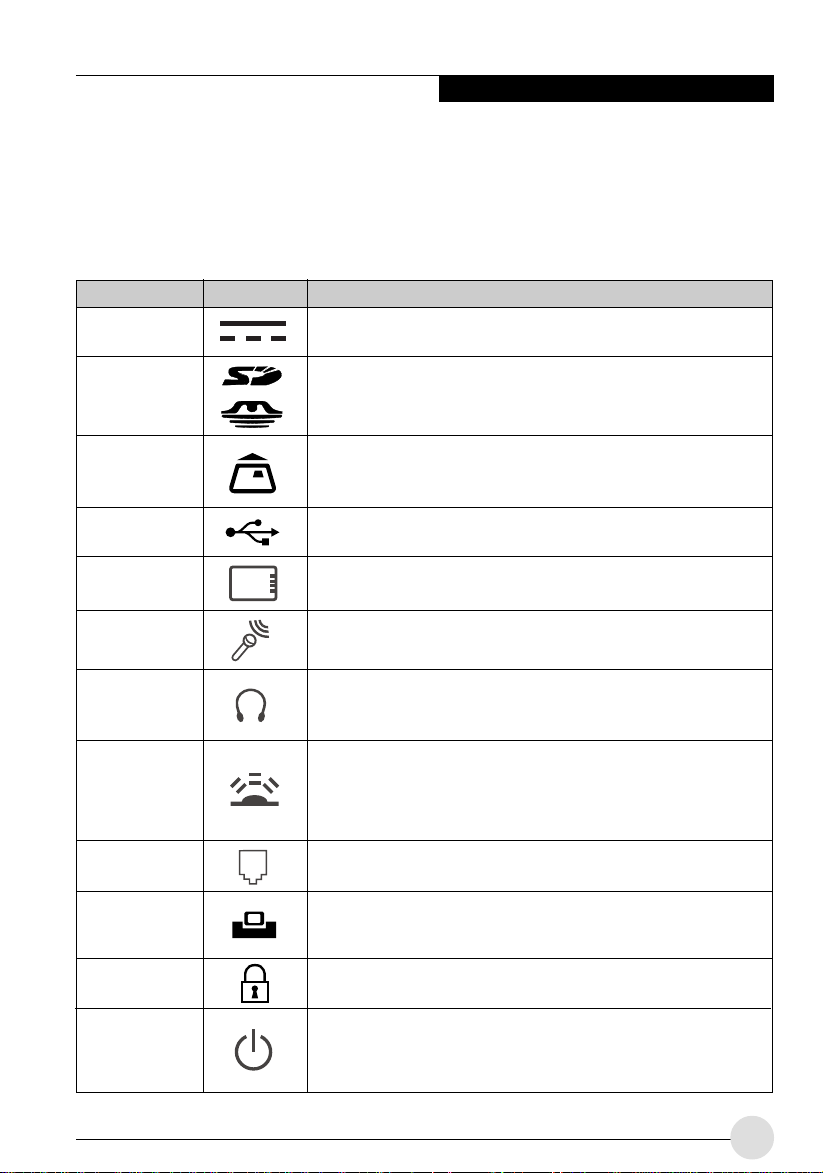
Figures 2-4 through 2-8. The table below pro vides
a short description of each icon on the LifeBook
T Series Tablet PC. Each of the icons is either
molded into or printed on the Tablet PC chassis.
Connection
DC in Connector
SD/Memory Stick
Slot
Smart Card Slot
USB Port
PCMCIA Card
Slot
Microphone Jack
Headphone Jack
IrDA/FIR Port
Modem
Tablet Dock Port
Security Lock Slot
Suspend/Resume
Button
Table PC Icon Purpose
Connect an external power source such as the AC adapter or auto/airline
adapter.
The Secure Digital (SD) card/Memory Stick slot allows you to install a
flash memory card for data storage. Flash memory cards allow you to
transfer data to and from a variety of different digital devices.
The dedicated Smart Card slot allows you to install a Smart Card on
which you can store such data as medical information or electronic
“cash”.
Connect Universal Serial Bus 2.0 or 1.1 compliant devices to the Tablet
PC.
Install Type I, Type II or Type III PC Cards.
Connect an external microphone. The internal microphone is disabled
when you plug in an external microphone.
Connect stereo headphones or powered external speakers. The internal
speaker is disabled when you plug in external headphones or powered
speakers.
An infrared transceiver built into the Tablet PC allows you to communicate
with other devices that are compliant with IrDA Standard Re v. 1.1.
Effective range for infrared communication is about 3 feet, and within 15
degrees off center. A clear line-of-sight path must exist between the IrDA
port on the computer and the IrDA transceiver on the other device.
Connect a telephone line to the internal modem using a standard RJ-11
telephone plug.
Connect the T Series Tablet PC Port Replicator or other approved
docking device. Refer to documentation accompanying the docking
device for more information.
The security slot allows you to secure the pen tablet PC using
Kensington-compatible locking devices.
The Suspend/Resume button allows you to suspend pen Tablet PC
activity without powering off, resume your pen tablet PC from suspend
mode, and power on the system when it has been shut down from
Windows.
7
Page 17
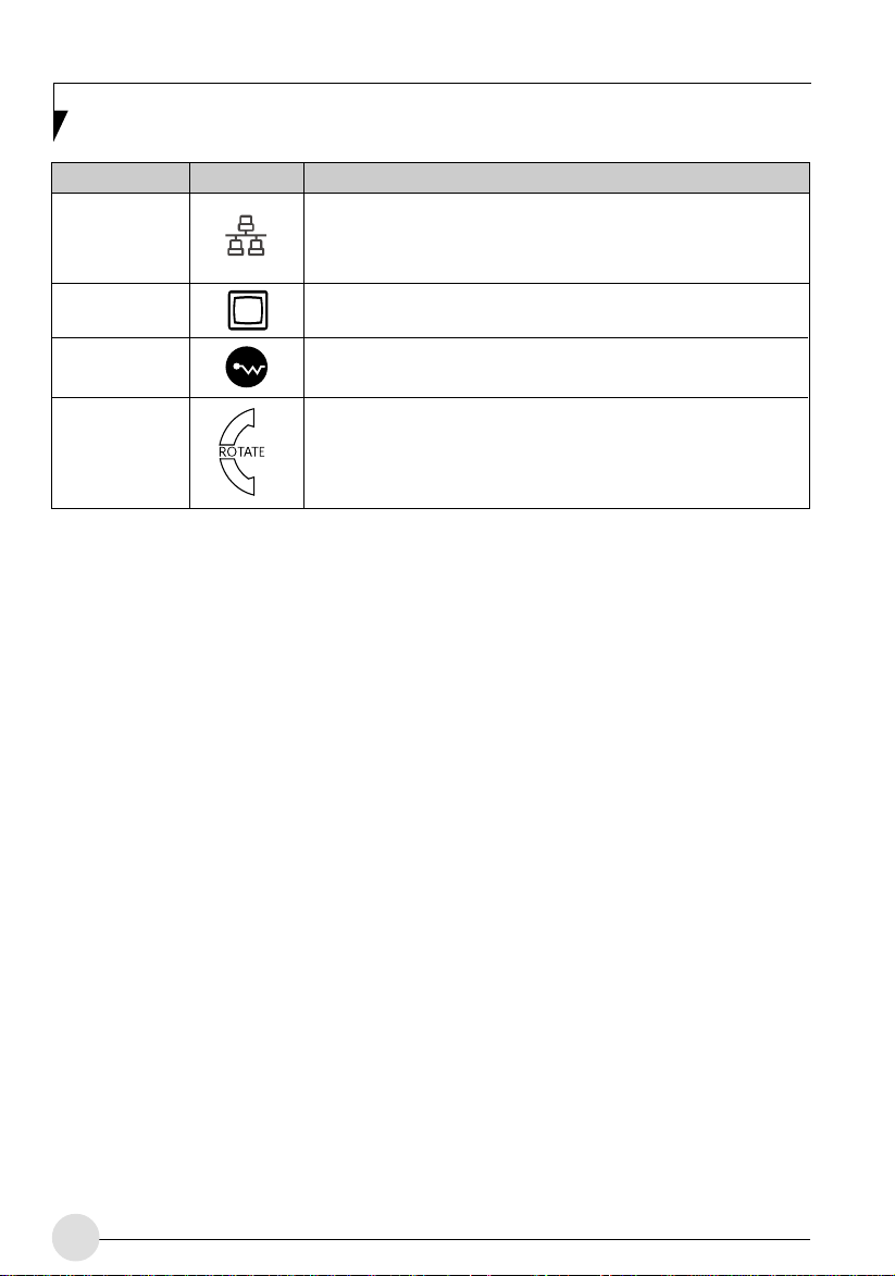
Connection
Local Area
External Video
port
Wireless LAN
On-Off Switch
Table PC Icon Purpose
The LAN (RJ-45) jack is used to connect the internal Fast Ethernet
(Gigabit Ethernet 1000/100/10Mbps) to a Local Area Network (LAN) in
your office or home, or broadband devices such as a cable modem, DSL,
or satellite internet.
The external video port allows you to connect an external monitor or LCD
projector to your computer.
The wireless LAN switch allows you to turn power to the optional wireless
LAN device on and off.
Display Rotation
This two-part light indicates the direction in which the display should be
rotated when converting back to notebook mode.
Depending upon which direction the display was rotated, either the top or
bottom indicator will light to indicate which direction to turn the display to
return to notebook mode.
Table 2-1 System icons
8
Page 18
Getting to Know Your Tablet PC
Built-in Microphone
Pen/
Pen Holder
Status Indicator Panel
Fingerprint Sensor
Display Rotation indicator
Rotation Hinge
SD/Memory
Stick Slot
Stereo Speaker
Headphone Jack
Microphone Jack
Display Panel
Release Button
Touchpad Pointing Device
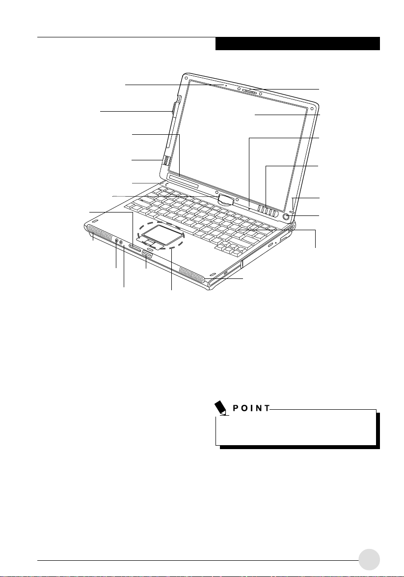
Figure 2-4. LifeBook T Series Tablet PC with display open
Top and Front Components
The following is a brief description of the top and
front features of the LifeBook T Series Tablet PC.
(Figure 2-4)
Pen
The pen is used as the interface with the active
digitizer display.
Display Panel Latch
The display panel latch locks and releases the
display panel.
Display Panel
The display panel is a color LCD panel with back
lighting for the display of text and graphics and
active digitizer functionality.
Display
Panel
Latch
Display
Panel
Built-in
Microphone
LifeBook Tablet
PC/Security
Buttons
Power Indicator
Suspend/
Resume
Button
Spill Resistant
Keyboard
Stereo Speaker
Fingerprint Sensor
The Fingerprint Sensor provides an alternative
way to Windows logon authentication and
homepages logon authentication. Please ref er to
the section on "Using Fingerprint Authentication"
for more details.
Some applications may not allow you to scroll
up and down a document.
Dual Digital Built-in Microphones
The Dual Digital built-in microphones allow you
to input mono audio.
9
Page 19

LifeBook Tablet PC/Security Button
The LifeBook T Series Tablet PC/Security Button
provide hardware security and application launch
capabilities.
Suspend/Resume Button
The Suspend/Resume button allows you to
suspend Tablet PC activity without powering off ,
resume your Tablet PC from standby mode, and
power on your system when it has been shut
down from the Windows operating system.
Spill Resistant Keyboard
A full-function keyboard with dedicated Windo ws
keys.
Headphone Jack
The headphone jack allows you to connect
headphones or powered external speakers.
Power Indicator
The power indicator shows the power state of
the system. Solid green indicates that power is
on, and blinking green indicates that the system
is in suspend mode.
SD Card/Memory Stick
The Secure Digital (SD) card/Memory Stick slot
allows you to install a flash memory card for data
storage. Flash memory cards allow you to transfer
data to and from a variety of different digital
devices.
Spill resistant keyboard does not imply the
keyboard is water-proof. If liquid is spilled
onto the keyboard, power off your notebook
immediately and turn the notebook upside
down to drain off the liquid.
Touchpad Pointing Device
The Touchpad pointing device consists of two
mouse-like buttons and one scroll button.
Stereo Speakers
The stereo speakers allow you to listen to stereo
sound from your system.
Microphone Jack
The microphone jack allows you to connect an
external mono microphone.
Rotation Hinge
The rotation hinge allows you to transform your
Tablet PC from a notebook configuration into a
tablet configuration.
Status Indicator Panel
The Status Indicator Panel displays symbols that
correspond to specific components of your
LifeBook T Series Tablet PC.
10
Page 20
Getting to Know Your Tablet PC
Pen Tether Attachment Point
USB 2.0 Port
DC Power
Jack
Wireless LAN/Bluetooth
On/Off Switch
Figure 2-5. LifeBook T Series Tablet PC left-side panel
Air Vents
Left-Side Panel Components
Following is a brief description of your T ablet PC’s
left-side components.
Pen Tether Attachment Point
The pen tether attachment point is designed to
securely hold a pen tether to prevent loss of the
pen.
USB 2.0 Port
The USB 2.0 port allows you to connect Universal
Serial Bus devices.
PC Card Slot
The PC Card Slot allows you to install a Type I or
Type II PC Card. The PC Card Eject Button is
used when ejecting a PC Card from the slot.
Wireless LAN/Bluetooth On/Off Switch
The wireless LAN/Bluetooth On/Off Switch is
used to power off the wireless antenna when not
in use.
(Figure 2-5)
PC Card Slot
Smart Card
Slot
Smart Card Slot
The dedicated Smart Card slot allows you to
install an optional Smart Card on which you can
store such data as medical information or
electronic “cash”.
DC Power Jack
The DC power jack allows you to plug in the AC
adapter to power your Tablet PC and charge the
internal Lithium ion Battery.
Air Vents
The air vents are used to cool the system to
prevent overheating.
Do not obstruct the air vents while the system
is running; doing so could cause your system
to overheat.
PC Card Eject/
Lock Button
11
Page 21

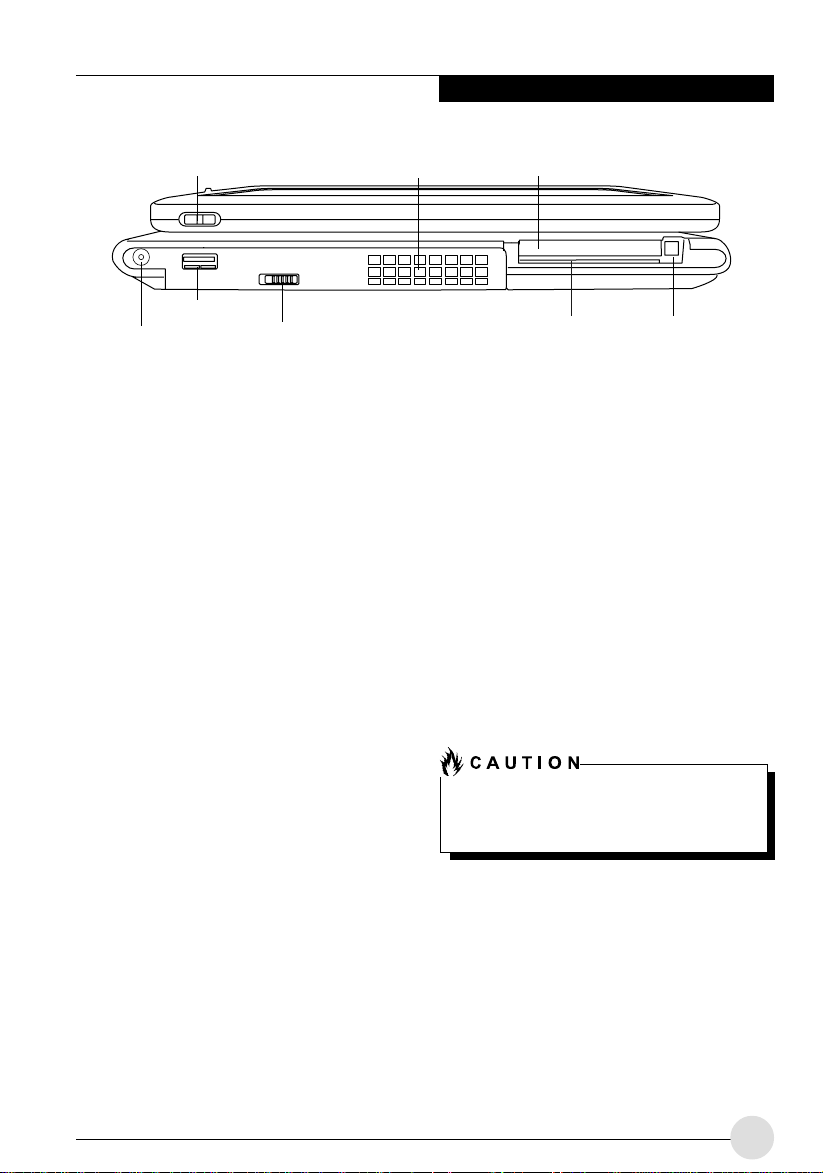
Anti-theft Lock Slot
Figure 2-6. LifeBook T Series Tablet PC right-side panel
Modular Bay
Anti-theft Lock Slot
Modular Bay Eject Lever
Right-Side Panel Components
Following is a brief description of your Tablet PC’s
right-side components.
Modular Bay
The Modular Bay can accommodate one of the
following devices.
• Modular DVD/CD-RW combo drive
• Modular Dual Layer DVD Super Multi Writer
• Modular DVD-ROM drive
• Modular Lithium ion battery
• Weight Saver
Modular Bay Eject Lever
The Modular Bay eject lever releases the Modular
Bay device.
Anti-theft Lock Slot
The anti-theft lock slot allows you to attach an
optional physical lock-down device.
12
Page 22
Getting to Know Your Tablet PC
Modem (RJ-11) Port
USB 2.0 Ports
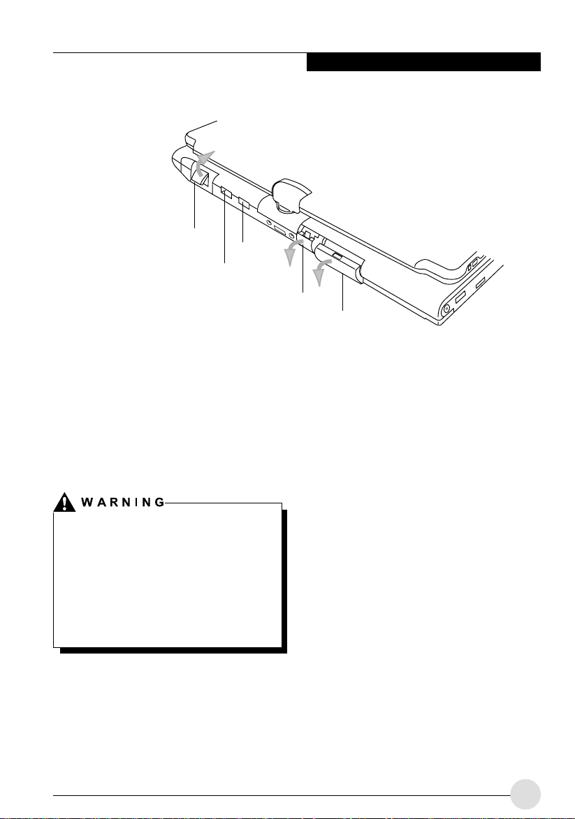
Figure 2-7. LifeBook T Series Tablet PC rear panel
Infrared Port
LAN (RJ-45) Jack
Rear Panel Components
Modem (RJ-11) Telephone Port
The Modem (RJ-11) telephone port is for
attaching a telephone line to the internal
multinational 56K modem.
The internal modem is not intended for use
with Digital PBX systems. Do not connect the
internal modem to a Digital PBX as it may
cause serious damage to the internal modem
or your entire LifeBook T Series Tablet PC.
Consult your PBX manufacturer’s
documentation for details. Some hotels hav e
Digital PBX systems. Be sure to find out
BEFORE you connect your modem.
External
Monitor Port
USB 2.0 Ports
The two USB 2.0 ports allow you to connect
Universal Serial Bus devices.
Infrared Port
The fast IrDA compatible port allows you to
communicate with another IrDA compatible
infrared device without a cable.
LAN (RJ-45) Jack
The optional internal LAN (RJ-45) port is used
for an internal Fast Ethernet (Gigabit Ethernet
1000/100/10Mbps) connection.
External Monitor Port
The external monitor port allows you to connect
an external VGA or SVGA monitor. Note that
when the optional Port Replicator is attached to
the system, you must use the external monitor
port on the Port Replicator rather than the port
on the system.
13
Page 23
Battery
Pack Latch
Lithium Ion
Battery Bay
Battery
Pack Latch
Port
Replicator
Connector
Memory
Upgrade
Compartment
Main Unit and
Configuration
Label
(approximate
location)
Air Vents
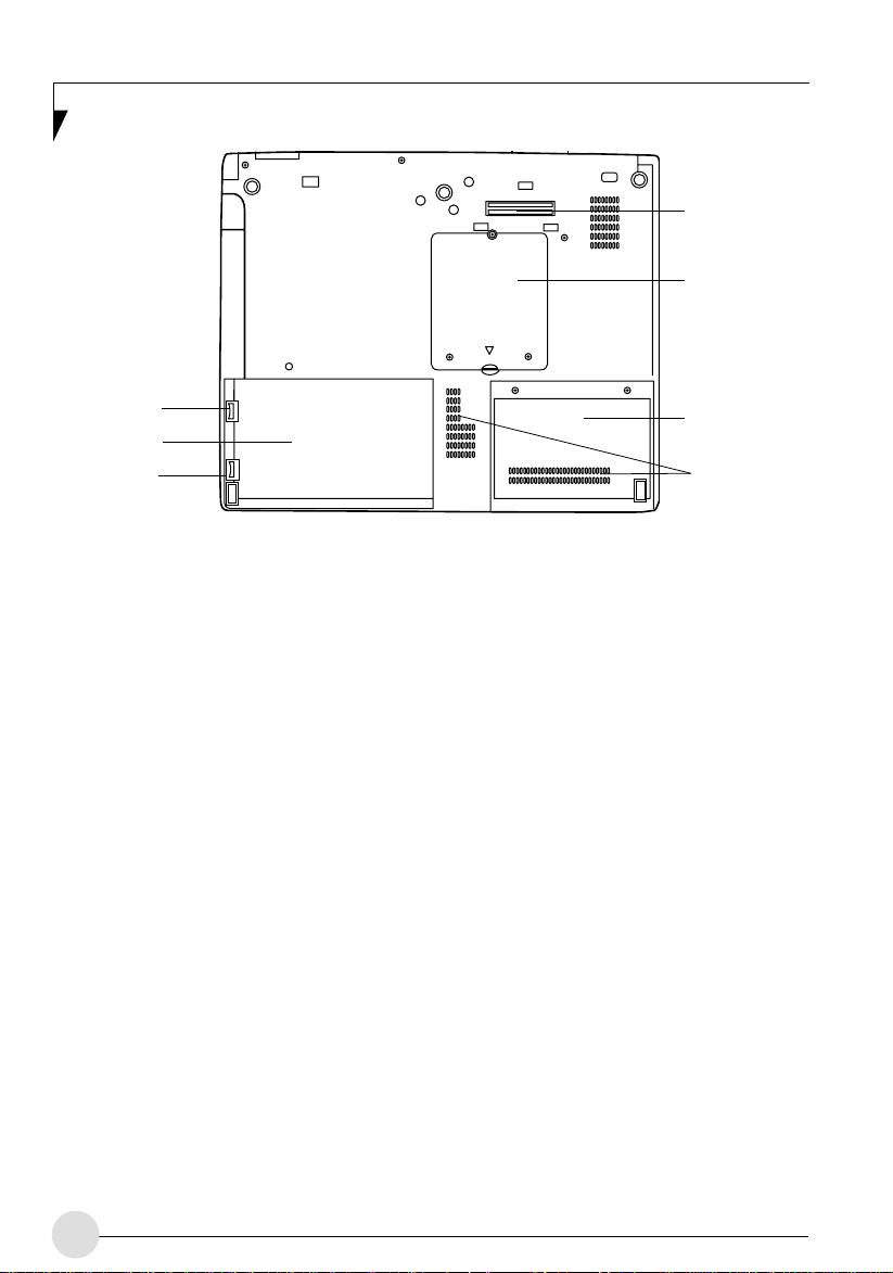
Figure 2-8. LifeBook T Series Tablet PC bottom panel
Bottom Components
Following is a brief description of your T ablet PC’s
bottom panel components.
Lithium Ion Battery Bay
The battery bay contains the internal Lithium Ion
battery. It can be opened for the removal of the
battery when stored over a long period of time or
for swapping a discharged battery with a charged
Lithium ion battery.
Port Replicator Connector
This connector allows you to connect the optional
Port Replicator.
(Figure 2-8)
14
Main Unit and Configuration Label
The configuration label shows the model number
and other information about your LifeBook T
Series Tablet PC. In addition, the configuration
portion of the label has the serial number and
manufacturer information that you will need to
give your support representative. It identifies the
exact version of various components of your
Tablet PC.
Memory Upgrade Compartment
Your Tablet PC comes with high speed
Synchronous Dynamic RAM (SDRAM). The
memory upgrade compartment allows you to
expand the system memory capacity of your
T ablet PC , hence improving over all performance.
Page 24
Getting to Know Your Tablet PC
AC Adapter
Battery 1
Charging
Battery 1
Level
Battery 2
Charging
Wireless LAN
Access
Battery 2
Level
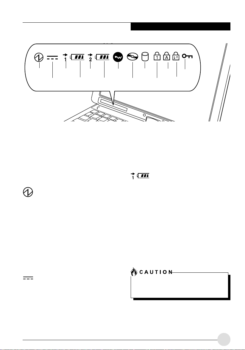
Figure 2-9. Status Indicator Panel
Power
Status Indicator Panel
The Status Indicator displays symbols that
correspond with a specific component of your
LifeBook T Series T ab let PC. These symbols tell
you how each of those components are
operating.
The Power indicator symbol states whether y our
system is operational. It has several different
states, each of which tells you what mode your
Tablet PC is in at that time.
• Steady On: This means that there is power to
• Flashing: This means that your Tablet PC is in
• Steady Off: This means that your system is
(Figure 2-9)
Power Indicator
your Tablet PC and that it is ready for use.
Standby mode.
either in Hibernate mode, or that your Tablet
PC has been turned off.
Hard Drive
Access
Optical Drive
Access
NumLk
CapsLk
ScrLk
Security
indicator
On: This means that either of the adapters are
currently in use.
Off: P ower is only coming from the batteries, and
you do not have an adapter connected.
Battery Charging/Level
Indicators
The Battery Charging and Battery Level
indicators state whether the Lithium ion battery
(Battery 1) or the optional modular battery
(Battery 2) are installed and charging, and how
much charge is available within the batteries.
(Figure 2-10)
Additionally, these indicators display when an
over-current is detected. If an overcurrent is
detected, the battery stops charging and the
Battery Level indicator blinks at the rate of once
per second. To stop the indicator from blinking,
you must disconnect the power adapter.
AC Adapter Indicator
The AC Adapter indicator states whether your
notebook is operating from the AC adapter, or
the batteries. This icon has two different states
that can tell you what power source your Lif eBook
notebook is using.
Batteries subjected to shocks, vibration or
extreme temperatures can be permanently
damaged.
15
Page 25
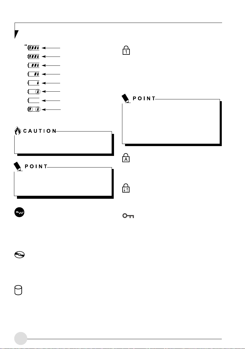
76%–100% Charging
76%–100%
51%–75%
26%–50%
11%–25%
Low Warning <11%
Critical Low or Dead
Battery
Shorted Battery
Figure 2-10 Battery Level Indicator
A shorted battery is damaged and must be
replaced.
If there is no battery activity and the power
adapters are not connected, the Battery
Level indicators will also be off.
(Figure 2-10)
Num Lock Indicator
The Num Lock indicator states that the integral
keyboard is set in ten-key n umeric keypad mode.
If there is no battery activity and the power
adapters are not connected, the Battery Level
indicators will also be off.
If you are using the optional external
numerical keypad, pressing the [NumLk] key
will activate the external keypad. The
indicator will come on, however it will not
change any of the functionality of your
keyboard keys.
Caps Lock Indicator
The Caps Lock indicator states that your
keyboard is set to type in all capital letters.
Scroll Lock Indicator
The Scroll Lock indicator states that your scroll
lock is active.
Wireless LAN/ Bluetooth
Access Indicator
The Wireless LAN/ Bluetooth Access indicator
is displayed when the optional internal wireless
LAN/ Bluetooth device is being accessed.
Optical Drive Access Indicator
The Optical Drive Access indicator states
whether your internal optical drive is being
accessed.
Hard Drive Access Indicator
The Hard Drive Access indicator states whether
your internal hard drive is being accessed.
16
Security Indicator
The Security Indicator flashes (if a password was
set) when the system resumes from Off or
Standby modes. You must enter the password
that was set in the Security Panel before your
system will resume operation.
Page 26

Figure 2-11. Opening the display
Display Panel
Your LifeBook T Series Tablet PC contains a
display panel that is backlit for easier viewing in
bright environments. The convertible design of
your Tablet PC allows you to open the display
fully, rotate it 180 degrees, and lay it face up on
the keyboard. This allows you to use the system
as a tablet, much as you would use a pad of
paper.
Opening the Display Panel
1. Press the latch release button. This releases
the locking mechanism. While holding the latch
release, lift display cover.
2. Lift the display backwards, being careful not
to touch the screen, until it is at a comfortable
viewing angle.
Using the System as a Tablet
If you would like to use the system as a tablet,
perform the following steps.
Rotate the system display only in the
direction indicated in the procedure.
Turning the display in the incorrect
direction could cause hinge damage.
In the following step, be sure to position
the display perpendicular to the keyboard,
otherwise the keyboard or display cover
could get scratched.
(Figure 2-11)
Getting to Know Your Tablet PC
Display Panel
Latch
Latch Release
Button
2. When the display is perpendicular to the
keyboard, rotate it 180 degrees in either
direction
backwards.
3. Holding the top edge of the display panel, pull
it forward until it is lying nearly atop the
keyboard.
4. Push the latch towards the display
Figure 2-12)
latch disappears, and the bottom latch
appears
latch down, lay the display flush against the
system so that the latch engages. Y ou can no w
use your system as a tablet.
5. To return the system to notebook
configuration, repeat step 3 and 2. Be sure to
turn the display in the direction indicated by
the display rotation light
(Figure 2-15)
so that it is facing
(Figure 2-16)
. The latch will pivot so the top
(See “B” in Figure 2-12)
Top latch
Bottom latch
Figure 2-12. Latching/Unlatching
(Figure 2-13).
(See “A” in
. Holding the
(Figure 2-17)
Display Side
1. Lift the display until it is per pendicular to the
keyboard.
(Figure 2-14)
Figure 2-13. Display rotation light
17
Page 27

Figure 2-14. Fully open display
Figure 2-15. Rotating the display
Figure 2-16. Display rotated completely
Figure 2-17. System in tablet configuration
Adjusting Display Panel Brightness
Once you have turned on your Tablet PC, you
may want to adjust the brightness level of the
screen to a more comfortable viewing lev el. There
are two ways to adjust the brightness, ke yboard
and power management utility.
18
Page 28

Using Keyboard to Adjust Brightness
Adjusting the brightness using the keyboard
changes the system setting (i.e., the settings you
make via the function keys automatically changes
the brightness settings in the system’s Pen and
Tablet Settings).
• [Fn+F6]: Pressing repeatedly will lower the
brightness of your display.
• [Fn+F7]: Pressing repeatedly will increase the
brightness of the display.
Using Power Management to Adjust
Brightness
T o adjust brightness with the power management
utility, click Start → Control Panel → Tab let and
Pen Settings.
Select the Display tab and set the screen
brightness slider for battery and AC power
scenarios.
Using the Fujitsu Menu to Adjust Brightness
T o adjust brightness using the Fujitsu menu, click
on the Fujitsu Menu icon in the system tray in
the lower right corner of the screen (or doubleclick the Function button). From the menu that
appears, select Brightness Control. The Tablet
and Pen Settings window will open. Select the
Display tab and set the screen brightness slider
for battery and AC power scenarios.
Getting to Know Your Tablet PC
If using AC power your brightness setting
is set to its highest level by def ault. If using
battery power your brightness settings is
set to approximately mid-level b y default.
The higher the brightness level, the more
power the LifeBook T Series Tablet PC
will consume and the faster your batteries
will discharge. For maximum battery life,
make sure that the brightness is set as
low as possible.
19
Page 29

Pen and Active Digitizer
Using the Pen
You can use the LifeBook T Series pen to
generate and create electronic “ink”, to select
items, and to navigate through programs on the
Tablet PC. Programs that support handwr iting
recognition also allow you to write characters
directly on the screen with the pen. You can also
use the pen as a drawing tool.
Eraser Button
Barrel Switch
Figure 2-24. LifeBook T Series Pen
The LifeBook T Series pen is a sophisticated,
high-quality electronic instrument that can be
damaged if used improperly. Treat the pen
as you would any precision device. The
following guidelines should be observed:
• Do not gesture with the pen, use it as a
pointer, or tap it on surfaces other than the
Tablet PC screen.
• Do not try to turn the thumb grip on the
pen; it is designed for inserting and
removing the pen from the pen holder.
• Never store the pen with the tip bearing
the weight of the pen (e.g., sitting tip down
in a pencil cup). Storing the pen tip down
could distort the internal mechanism over
a period of time (especially in higher
temperatures), causing the tip to act as if it
is always depressed. To avoid damage, the
pen should be stored in the pen holder
when not in use.
Tip Switch
The screen reacts when the pen tip is
approximately 1/8 inch (3-5mm) from the screen.
The pen has three switches: a tip switch and a
barrel button toggle switch with switches at both
ends. When activated, the tip s witch corresponds
to the left mouse button, and the front toggle
(closest to the pen tip) barrel button switch, when
used in combination with the tip switch,
corresponds to the right mouse button. The rear
toggle of the barrel button switch is programmab le
and by default, corresponds to a left-double-clic k
of a mouse. You can also program it to act as an
electronic ink "eraser".
The functions of the rear toggle and the tip click
pressure can be changed by clicking [Start] ->
Control Panel, and double-clicking the Fujitsu P en
Settings icon.
To change the rear toggle function, select the
drop-down list to select a new function, then click
[Apply]. If y ou don’t want the rear toggle to have
any function, select Ignore from the list.
Adjusting the click pressure determines how
much pressure must be put on the pen tip in order
for the screen to react. The softer it is set, less
pressure is required; the harder it is set, more
pressure is required. To change the click
pressure, use the slider bar to make the click
pressure harder or softer, then click [Apply].
• Use only the pen provided with your T ab let
PC. Do not use substitutes that were not
designed for the LifeBook T Series Tablet
PC.
Here are some hints that may help you use the
pen more effectively:
• To activate the tip switch, tap or hold the pen
tip against the screen.
• To activate the barrel button switch, press
and hold the end of the button you wish to use
(front toggle is the right mouse button switch;
the rear toggle acts as an electronic “eraser”).
20
Page 30

Getting to Know Your Tablet PC
• To move the cursor , hold the pen tip within 1/
8 inch (3-5mm) from the screen and move the
pen.
• To start a program, double-tap the pen tip
(tap the pen tip twice rapidly) on the program
icon as you would double-click a mouse.
• To select an object, tap the pen tip on the
object once.
• To “double-click” an object, quickly tap the
object twice.
Calibrating the Pen
In order to ensure accurate tracking between the
pen and cursor, you must run the Touch Screen
Calibration Utility before you use the Touch
Screen for the first time, or after you change the
display resolution.
To run the calibration utility:
1. Go to Start → Contr ol Panel and double-clic k
on the Tab let and Pen Settings icon.
2. Click Calibrate.
3. Adjust the display of your Tablet PC to a
comfortable angle.
4. Using the pen, firmly touch the screen directly
on the (+) symbol; the pen tip, the (+) symbol
will move to the next location.
5. Repeat step 4 in the four corners of the screen,
then click OK.
Replacing the Pen Tip
With use, the pen tip may become worn or may
pick up foreign particles that can scratch the
screen. A damaged or worn tip may not move
freely , causing unpredictable results when using
the pen. If your pen e xhibits these problems, y ou
should replace the pen tip. To do so, use the pen
tip removal tool included with your pen.
Gap
Figure 2-26. Tip Removal Tool
To remove the tip, position the tip in the gap
between the two ends of the tool
26)
. Pinch the tool together so the tip is firmly
clasped, then pull it from the barrel. If the tip is
worn or damaged, discard it.
To replace the tip, retrieve one of the new tips
that accompanied your pen. Insert the flat end of
the tip into the barrel and push it in firmly until it
is seated.
(See Figure 2-
21
Page 31

Using the Active Digitizer
The integrated Active Digitizer allows y ou to use
the included pen as a pointing device. You can
use the pen to click, double-click, drag items and
icons, or to draw like a pen or pencil in
applications that support this behavior, such as
drawing or painting programs. See the
documentation that came with your application
for details.
(Figure 2-27)
Figure 2-27. Using the pen with the Screen
To avoid potential scratching and damage,
never use anything b ut the included pen with
the display.
Figure 2-28. Clicking the Screen
Double-Clicking
To double-click, touch the item twice, and then
immediately remove the pen tip.
(Figure 2-29)
Clicking
To left-click, touch the object you wish to select
and then lift the pen tip immediately .
(Figure 2-28)
T o right-click, press the front b utton on the barrel
switch or touch the pen to the screen for a couple
of seconds until the right mouse icon appears at
the tip.
22
Figure 2-29. Double-clicking the screen
If the interval between taps is too long,
the double-click will not be executed.
Parameters for the Touch Screen can be
adjusted from the Mouse Properties
dialog box located in the Windows Control
Panel.
Page 32

(2) Application B Button (4) Button 4
(1) Application A Button (3) Button 3
Figure 2-18. LifeBook T Series Tablet PC Security/Tablet PC Buttons
LifeBook Tablet PC/Security
Buttons
A unique feature of your Lif eBook T Series T ab let
PC is the array of Security and Tablet PC buttons.
These buttons allow you to secure your Tablet
PC from unauthorized use and to launch specific
applications with the touch of a button.
If the security system is activated, upon starting
your Tablet PC or resuming from Standby,
Hibernate, or shut-down mode the security
system will require you to enter a password code
using the security buttons. After you enter the
correct password, your Tablet PC will resume
operation.
The five security/Tablet PC buttons are located
on the bottom right-hand side of the display when
it is configured to be used as a notebook.
(Figure 2-18)
Security functions: All five buttons are used
when implementing security functions. Four of
Button Icon
Primary Function
Page Down
Page Up
Screen Rotation
Secondary Function
Selection
Ctl+Alt+Del Button
User-defined Application A
(Default = Calculator)
User-defined Application B
(Default = MS Journal)
Getting to Know Your Tablet PC
Enter Button
the buttons are used to enter the password, and
the fifth is used as an Enter button. See the righthand column of Table 2-2.
T ablet PC functions: All five of the buttons ha ve
primary functions. Four of the buttons have
secondary functions when used as application
buttons. The secondary functions are activated
by pressing the Function (Fn) button while
pressing the application button. See Table 2-2
for specific functions. The secondary functions
of the Application A and B buttons can be
changed to launch any application.
When the system is logging on or when it is
locked (i.e., when you have the Logon or
Computer Locked window showing on your
desktop), the A and B buttons act as [Tab]
and [Enter] keys, respectively.
Secondary Function
(Fn + Button)
VGA-Out
Fujitsu Utility Menu
None
Security Panel Function
(Pre-boot and resuming
from suspend)
Security Button 1
Security Button 2
Security Button 3
Security Button 4
Security Enter Button
Table 2-2 Security/Tablet PC Button Functions
23
Page 33

Page Down/Application A Button
When you press the Page Down button when
the system is running, each press of the button
will scroll the screen down one frame. This allo ws
you to navigate quickly through large documents.
When you press the Fn button and hold it while
you press the Page Down/Application A b utton,
you will automatically start whichever program
is assigned to the button. The def ault application
for this button is Calculator.
Page Up/Application B Button
When you press the Page Up button when the
system is running, each press of the button will
scroll the screen up one frame. This allows you
to navigate quickly through large documents.
When you press the Fn button and hold it while
you press the Page Up/Application A button,
you will automatically start whichever program
is assigned to the button. The def ault application
for this button is Microsoft Journal.
When you press the Screen Rotation / VGA-
Out button, the system screen orientation
changes from portrait (vertical) to landscape
(horizontal) or from landscape to
portrait.
Function/Fujitsu Menu Button
The Function button works in conjunction with
the other application buttons to provide additional
functionality for the buttons. Refer to specific
details above.*
Pressing the Fn button twice in succession
causes the Fujitsu Utility Menu to appear on your
screen, allowing you to modify certain system
settings.
Ctl+Alt+Del Button
Pressing the Ctl-Alt-Del button for up to two
seconds launches the Logon screen or the
Windows Task Manager (if the system hasn’t yet
been configured).
Screen Rotation/VGA-Out Button
The screen rotation feature would normally be
used only when the system is configured as a
tablet. When you would like to use the tablet as
an eBook, for example, y ou would use the portrait
orientation; when accessing spreadsheets or
using the system as a notebook, you would more
typically use landscape orientation.
When the system is changed to tablet
configuration, the orientation automatically
changes to portrait mode by default.
The screen orientation default can be
changed by going to the Control Panel and
double-clicking on the Fujitsu Display Control
icon and selecting the desired defaults from
the Display Orientation section. After
changing the defaults, click [OK].
24
Changing Tablet PC Button
Functions
The Application A and B buttons can be changed
to launch a program or perform an action you
select. By default, the Application A button
launches the Calculator, and the Application B
button launches MS Journal.
To launch different applications or cause the
Application A or B buttons to perform a specific
action:
1. Double-click on the Tablet and Pen Settings
icon in the Control Panel.
2. Select the Tablet Buttons tab and select the
button you would like to change from the list.
3. Click [Change] and open the drop down list in
the Action: field.
4. Select the action you would like the button to
perform. If y ou want to launch a program, click
on Launch an Application then browse to the
location of the program.
5. Click [OK], then click [OK] again. The b uttons
will now perform the actions you have
assigned to them.
Page 34

Setting Up Lifebook Security Panel
When you receive your Tablet PC, the security
panel application is pre-installed without any
passwords. The following sections provide
detailed information on your security panel, how
to set, change or remove passwords.
Numbered Buttons
Use these buttons to enter your password.
(Figure 2-18)
Enter Button
After entering the button strokes, push this button
to enter the password into the T ab let PC.
(Figure
2-18)
Passwords
The user and supervisor password may be set
on this Tablet PC. A supervisor password is
typically the same for all tablets and notebooks
in a work group, office, or company to allow for
system management. Individual computers in a
group environment should not use a common
password. A password consists of one to five
button strokes plus the enter button. A valid strok e
consists of pushing one or up to four buttons
simulta-neously.
The following are valid button strokes:
• Pushing [4] by itself
• Pushing [2] and [3] at the same time
• Pushing [1], [2], and [4] at the same time
• Pushing [1], [2], [3], and [4] at the same time
The following are valid pass words. The n umbers
within braces ({ }) are button strokes using more
than one button.
• {[2]+[3]}, [1], [Enter]
• [4], [enter]
• {[1]+[3]}, {[2]+[3]+[4]}, [1], [4], [2], [Enter]
Getting to Know Your Tablet PC
a The purpose of supervisor password is to
be able to bypass the user password in
case the user password is forgotten. The
supervisor password alone will not lock
the system.
a You must set the supervisor and user
passwords for the security panel to work.
Setting Supervisor Password
Y ou m ust have set a supervisor password bef ore
setting any user passwords. The supervisor
password can bypass the user password.
1. Go to the Start menu.
2. Click on Run.
3. Type in:
C:\Program Files\Fujitsu\Security
Panel Application\Supervisor\
FJSECS.EXE, then press [Enter].
4. Follow the on-screen instructions to set the
Supervisor password.
Setting User Password
1. Go to the Start menu.
2. Click on All Programs.
3. Click on Security Panel Application ->
Security Panel Application.
4. Follow the on-screen instructions to set the
user password.
You may change or remove the supervisor
or user password by repeating the steps
defined above.
Setting Passwords
When shipped from the factory, no passwords
are set. You have a choice of having no password
or setting a supervisor and user password. You
must set the super-visor password before the
user password.
25
Page 35

Using Your Lifebook Security Panel
The security lock feature is in effect both when
the system resumes from Off, Standby, or
Hibernation state. You always need to push the
Security Panel buttons to input the user
password. Your system will not begin the boot
sequence until you enter your supervisor/user
password.
From Off State
1. Turn on your system.
2. When the Security Indicator flashes, enter
the pass-word and press Enter button.
For example, if the password is 22222, first
press Button 2 five times and press the Enter
button. The Tablet PC will boot to normal
operation.
From Standby/Hibernation State
1. Press your Suspend/Resume button.
2. When the Security Indicator flashes, enter
the pass-word and press Enter button.
The Tablet PC should resume normal
operation.
Incorrect Password Entry
If an invalid supervisor or user password is
entered three times in succession, the system
will “beep” for about one minute. If a valid
password is entered within a minute (while
system beeps), the beeping will stop and the
Tablet PC will resume normal operation. If no
password is entered or an invalid password is
entered while the system beeps, the system will
return to its previous locked state (standby or off)
and the Security Indicator will go off. To reactivate
the Tablet PC after a passw ord f ailure , y ou must
press the Suspend/Resume button, then enter a
correct password.
Remember the user password you specified
on the Security Panel Application. If you
forget the password you will not be able to
use your computer. The supervisor password
can override the user password.
Precautions
Opening and Closing the Cover
By default, closing the cover automatically places
your system into Standby mode. (You can change
the action the system takes when the cover is
closed by opening the Po wer Options Properties
icon in the Control Panel, and selecting the
Advanced tab. Make a choice from the drop do wn
menu for “When I close the lid of my por table
computer:” and click the [OK] button.) Opening
the cover does not automatically place the T ab let
PC into normal operation. Instead, you must enter
the proper security password after pushing the
Suspend/Resume button.
Low Battery Operations
If your Tablet PC has a low battery, pushing the
suspend/resume button only turns on the
Security Indi-cator. Your Tablet PC does not
unlock, the Security Indicator turns off after one
minute. T o resume normal operation, first attach
a power supply to the Tablet PC. Then you may
unlock the Tablet PC.
Uninstalling The Security Panel
Application
You have two options when uninstalling the
security panel application:
• Remove passwords and uninstall the security
panel application software. This will disab le all
security features.
• Uninstall the secur ity panel application with
password still active. This will not allow any
changes to the password.
Uninstalling the Security Panel Application
Software
Remove passwords when User wants no
password protection whatsoever and doesn’t
want to give anybody the utility to set a passw ord
on their computer. In this case, if passwords
(supervisor, user, or both) are set, the pass words
must first be cleared BEFORE removing the
application. To clear passwords, follow same
procedure in SETTING PASSWORD CODES
except this time, select REMOVE, enter current
password then click Ne xt. When asked to confirm
select Yes.
26
Page 36

Getting to Know Your Tablet PC
Removing Security Panel Application with
Passwords Still Active
Using this feature will not allow any changes to
the password.
Removing the applications does not remove
the password. It simply remov es the utility to
change/add/remove passwords. To change
your password you must reinstall the
application.
User:
1. Go to Start -> Control Panel.
2. Open Add or Remove Programs
Properties in the Control Panel.
3. Select the Security Panel Application in the
list, and click Change/Remove.
4. When the Confirm File Deletion box appears,
click Yes.
Supervisor:
1. Go to Start -> Control Panel.
2. Open Add or Remove Programs
Properties in the Control Panel.
3. Select the Security Panel Application for
Supervisor in the list, and click Change/
Remove.
4. When the Confirm File Deletion box appears,
click Yes.
2. Go to the Utilities\Security Panel
Application\User folder on the CD and
double-click the setup .ex e file. The Installing
Security Panel Application window will
appear. Follow the instructions on the screen.
Supervisor and user passwords can be set via
Windows software using the FJSECS.exe and
FJSECU.ex e files, respectively. FJSECU.ex e for
the user password cannot run without first
setting a supervisor password. You need to run
FJSECS.exe first to set the supervisor
password. Follow instructions under Setting
Passwords on page 25.
If you forget both passwords, please contact
Fujitsu Computer Systems Corporation Service
and Support at 1-800-8FUJITSU (1-800-838-
5487). Fujitsu Computer Systems Corporation
charges a service fee for unlocking a pass wordrestricted Tablet PC. When calling please hav e a
valid credit card and provide proof of ownership .
You will then be given instructions on where to
ship your Tablet PC.
Reinstalling the Security Panel Application
To reinstall supervisor or user security
application, you will need your Drivers and
Applications CD. The Utilities\Security Panel
Application folder contains two separate folders:
Supervisor and User. The setup files for
supervisor and user security applications are
contained in those folders.
1. Go to the Utilities\Security Panel Application\
Supervisor folder on the CD and double-click
the setup.exe file. The Installing Security
Panel Application window will appear . Follow
the instructions on the screen.
27
Page 37

3
Using Y our Tablet
PC
28
Page 38

Using Your Tablet PC
29
Page 39

DC Power Plug
DC Output Cable
AC Cable
Figure 3-1. Connecting the AC Adapter
Power Sources
Your LifeBook T Series Tablet PC has two
possible power sources: a primar y Lithium ion
battery and an AC adapter.
Connecting the Power Adapters
The AC adapter provides power for operating
your Tablet PC and charging the batteries.
Connecting the AC Adapter
1. Plug the DC output cable into the DC power
jack of your Tablet PC.
2. Plug the AC adapter into an AC electrical outlet.
(Figure 3-1)
Connecting the Optional Auto/Airline Adapter
1. Plug the DC output cable into the DC power
jack on your Tablet PC.
AC Adapter
2. Plug the A uto/Airline adapter into the cigarette
lighter of an automobile with the ignition key
in the On or Accessories position.
OR
3. Plug the A uto/Airline adapter into the DC power
jack on an airplane seat.
Switching from AC Adapter Power to Battery
Power
1. Be sure that you have a charged battery
installed.
2. Remove the AC adapter.
The Lithium ion battery is not charged upon
purchase. Initially, you will need to connect
the AC adapter to use your Tablet PC.
30
Page 40

Using Your Tablet PC
Starting Y our T ablet PC
Power On
The Power/Suspend/Resume button is used to
turn on your LifeBook T Series Tablet PC from
its off state. Once you have connected your AC
adapter or charged the internal Lithium ion
battery, you can power on your Tablet PC.
When you turn on your Tablet PC be sure
you have a power source. This means that
a battery is installed and charged, or that
the AC adapter is connected and has power .
Press the Power/Suspend/Resume button to
start your system. When you are done working
you can either leave your Tablet PC in Standby
mode, or you can turn it off.
When the system display is closed, the
Suspend/Resume button is disabled. This
feature prevents the system from being
accidentally powered up when not in use.
When you Power On your Tablet PC, it will
perform a Power On Self Test (POST) to check
the internal parts and configuration for correct
functionality. If a fault is found, your Tablet PC
will emit an audio warning and/or an error
message will be displayed. Depending on the
nature of the problem, you may be able to
continue by starting the operating system or by
entering the BIOS setup utility and revising the
settings.
After satisfactory completion of the Power On
Self Test (POST), your Tablet PC will load your
operating system.
Boot Sequence
The procedure for starting-up your Tablet PC is
termed the Bootup sequence and involves your
Tablet PC’s BIOS. When your Tablet PC is first
turned on, the main system memory is empty,
and it needs to find instructions to start up your
Tablet PC. This information is in the BIOS
program. Each time y ou power up or restart your
Tablet PC, it goes through a boot sequence
which displays a Fujitsu logo until your operating
system is loaded. During booting, your Tablet
PC is performing a standard boot sequence
including a Power On Self Test (POST). When
the boot sequence is completed without a failure
and without a request for the BIOS Setup Utility ,
the system displays the operating system’s
opening screen.
The boot sequence is executed when:
• You turn on the power to your Tablet PC.
• You restart your Tablet PC from the Windows
Shut Down dialog box.
• The software initiates a system restart.
Example: When you install a new application.
• You reset the system by pressing the three
keys [Ctrl+Alt+Del].
Registering your LifeBook T Series
Tablet PC
How do I register?
To register your system, visit our Web site at:
www.pc-ap.fujitsu.com
Never turn off your Tablet PC during the
Power On Self Test (POST) or it will cause
an error message to be displayed when you
turn your Tablet PC on the next time.
31
Page 41

Power Management
Your LifeBook T Series Tablet PC has many
options and features for conserving battery
power. Some of these f eatures are automatic and
need no user intervention, such as those for the
internal modem. Howev er , others depend on the
parameters you set to best suit your operating
conditions, such as those for the display
brightness. Internal power management f or your
T ab let PC may be controlled from settings made
in your operating system, pre-bundled power
management application, or from settings made
in BIOS setup utility.
Power Mode
Fully On Mode
Standby Mode
(Suspend-to-RAM)
Hibernation Mode
(Suspend-to-Disk)
Power Off
System Activity
System is running. CPU, system
bus, and all other interfaces
operate at full speed.
Resume system logic remains
powered and RAM remains
powered to maintain active data.
All other devices are turned off.
Windows saves desktop state
(including open files and
documents) to hard disk. CPU
stops. All other devices are
turned off.
System is fully powered off
except for logic components
required for Suspend/Resume
button and real-time clock
operation.
Besides the options available for conserving
battery power, there are also some things that
you can do to prevent y our Tablet PC battery from
running down as quickly. For example, you can
create an appropriate power saving profile, put
your Tablet PC into Standby mode when it is not
performing an operation, and you can limit the
use of high power devices. As with all mobile,
battery powered computers, there is a trade-off
between performance and power savings.
Events causing system to enter mode state
• From Standby mode: System operation resumed
(Suspend/Resume button pressed, resume on
modem ring, resume on time).
• From Hibernation mode: Suspend/Resume button
pressed.
• From Off mode: Suspend/Resume button pressed.
• Standby timeout occurs.
• Suspend request issued by software or by pressing
the Suspend/Resume button.
• Low battery.
• Suspend timeout occurs.
• Clicking Start -> Shut Down -> Hibernate (It may be
necessary to Enable Hibernate Support from
Windows Power Options.)
• Low battery condition.
• System shutdown.
• Low battery condition.
Table 3-1. System Power States
Suspend/Resume Button
When your Tablet PC is active, the Suspend/
Resume button can be used to manually put your
T ablet PC into Standb y mode. Push the Suspend/
Resume button when your T ablet PC is activ e, but
not actively accessing anything, and immediately
release the button. You will hear two short beeps
and your system will enter Standby mode.
If your Tablet PC is suspended, pushing the
Suspend/Resume button will return your Tablet
32
PC to active operation. You can tell whether or
not your system is in Standby mode by looking
at the Power indicator. If the indicator is visible
and not flashing, your Tablet PC is fully
operational. If the indicator is both visible and
flashing, your Tablet PC is in Standby mode. If
the indicator is not visible at all, the power is off
or your Tablet PC is in Hibernate mode
(See
Hibernate Mode)
Page 42

Using Your Tablet PC
Standby Mode
Standby mode in Windows saves the contents
of your Tablet PC’s system memory during
periods of inactivity by maintaining power to
critical parts. This mode will turn off the CPU , the
display , the hard drive, and all of the other internal
components except those necessary to maintain
system memory and allow for restarting. Your
Tablet PC can be put in Standby mode by:
• Pressing the Suspend/Resume button when
your system is turned on.
• Selecting Standby from the Windows Shut
Down menu.
• Timing out from lack of activity.
• Allowing the battery to reach the Dead Battery
Warning condition.
• Closing the system cover.
Y our T ablet PC’s system memory typically stores
the file(s) on which you are working, open
application(s) information, and any other data
required to support the operation(s) in progress.
When you resume operation from Standby mode,
your Tablet PC will return to the point where it
left off. To resume operation, you must use the
Suspend/Resume button to resume operation,
and there must be an adequate power source
available, or your Tablet PC will not resume.
If you are running your Tablet PC on battery
power, be aware that the battery continues
to discharge while your Tablet PC is in
Standby mode, though not as fast as when
fully operational.
Hibernate Mode
The Hibernate mode saves the contents of your
T ab let PC’s system memory to the hard drive as
a part of the Suspend/Resume mode. Your T ablet
PC is preconfigured to perform this function. The
Hibernate mode can also be configured through
the system BIOS to run in other ways depending
on what you need to accomplish.
Standby or Hibernate modes should not
be used with certain PC Cards. Check
your PC Card documentation for more
information.
Disabling the Suspend/Resume button
prevents it from being used to put your
T ablet PC in Standby or Hibernate mode.
The resume function of the button cannot
be disabled.
If your Tablet PC is actively accessing
information when you enter Standby or
Hibernate mode, changes to open files
are not lost. The files are left open and
memory is kept active during Standby
mode or the memory is transferred to the
hard drive during Hibernate mode.
When PC Cards or external devices are
in use, Save-to-Disk mode cannot return
to the exact state prior to suspension,
because all peripheral devices will be
reinitialized when the system restarts.
The main advantage of using Hibernate
mode is that power is not required to
maintain your data. This is very important
if you will be leaving your Tablet PC in a
suspended state for a prolonged period
of time. The dra wback of using Hibernate
mode is that it lengthens the power down
and power up sequences and resets
peripheral devices.
33
Page 43

Using Hibernate Mode
Hibernate default setting is enabled for Windows XP.
To enable or disable the Hibernation feature
follow these easy steps:
1. From the Start menu, select Settings, and
then select Control Panel → Power
Management.
2. Select Hibernation, and then select the box to
enable or disable this feature.
To use Hibernate mode with Windows XP
systems:
1. Click on the Start button, click Shut Down.
2. Select Hibernate option from the “What do you
want the computer to do” list.
Display Timeout
The Video Timeout is one of the power
management parameters. This feature saves
power by turning off the display if there is no
keyboard or pointer activity for the user selected
timeout period. Any keyboard or pointer activity
will cause the display to restart automatically . This
feature is independent of the Suspend/Resume
button and can be enabled and disabled in
Windows Power Management.
Hard Disk Timeout
The Hard Disk Timeout is another one of the
power management parameters. This feature
saves power b y turning off the hard drive if there
is no hard drive activity for the user selected
timeout period. Any attempt to access the hard
drive will cause it to restart automatically. This
feature is independent of the Suspend/Resume
button and can be enabled and disabled in
Windows.
Windows Power Management
The Power Management icon located in the Windows
Control Panel allows you to configure some of the
power management settings. F or e xample , you can
use the Power Management to set the timeout v alues
for turning off the display and hard disks whether you
are running the T ab let PC on battery power or one of
the adapters..
Restarting the System
If your system is on and you need to restart it, be
sure that you use the following procedure.
1. Click the Start button, and then click Shut
Down.
2. Select the Restart option from within the
Windows Shut Down dialog box.
3. Click OK. Your Tablet PC will shut down and
reboot.
Turning off your Tablet PC without exiting
Windows or turning on your Tablet PC within
10 seconds of the Tablet PC being shut off
may cause an error when you start the next
time.
Power Off
Before turning off the power by choosing Shut
Down from the Windows Start menu, check that
the Hard Drive, CD-ROM, PC Card and the
Floppy Disk Drive Access indicators are all Off.
If you turn off the power while accessing a disk
or PC Card there is a risk of data loss. To assure
that your Tablet PC shuts down without error, use
the Windows shut down procedure.
Using the correct procedure to shut down from
Windows, allows your Tablet PC to complete its
operations and turn off power in the proper
sequence to avoid errors. The proper sequence
is:
1. Click the Start button, and then click Shut
Down.
2. Select the Shut Down option from within the
Windows Shut Down dialog box.
3. Click OK.
If you are going to store your Tablet PC for a
month or more see the Care and Maintenance
section.
34
Page 44

Using Your Tablet PC
Using fingerprint
authentication*
With fingerprint authentication, you can omit
entering a user name and a password by just
sliding your finger onto the fingerprint sensor at
the time of logging in homepages or logging on
Windows. This chapter describes how to use
fingerprint authentication.
* NOTE:
This is only applicable for LifeBook with
Fingerprint Sensor.
To use fingerprint authentication, the user’s
fingerprints must be registered.
Characteristics of fingerprint
authentication
Fingerprint authentication can be
used in the following case.
• Logging on to Windows
When the user account of Windows is
password-protected, only persons who know
that password can log on to Windows using
that account. Ho wever , you ha ve to enter the
password each time when you log on to
Windows.
With use of fingerprint authentication, you
can log on to Windows by only authenticating
fingerprints that have previously been
registered, thus omitting entering a
password.
• Recovery from the power-saving status
If the computer is password-protected for the
recovery from power-saving status, y ou have
to enter a password each time when your
computer is recovered from the power-sa ving
status.
With use of fingerprint authentication, you
can recover from the power-sa ving status by
authenticating fingerprints that have
previously been registered, thus omitting
entering a password.
You can log on
to Windows or
recover from the
power-saving
status by
authenticating
the fingerprints
It is unnecessary to input
a password.
• Canceling password-protected screen
saver
You can lock your computer if the screen
saver is password-protected. However, you
have to cancel this lock when canceling the
screen saver .
With use of fingerprint authentication, just
authenticating fingerprints that have
previously been registered enables this lock
to be canceled, thus omitting entering a
password.
• Logging into the homepage that requires
an ID (user name) and a password
To log into the homepage of which security
is set up, you may have to enter log-in
information such as an ID (user name) and
a password.
With fingerprint authentication, you can log
into these homepages by just authenticating
fingerprints if log-in information is previously
memorized for specific homepages.
Status for entering log-in information differs
depending on homepages; direct entering
log-in information into homepages, and
indication of screens specific to entering. In
either case, log-in using fingerprint
authentication can be performed.
that have been
registered.
35
Page 45

Configuration of registration
information
Register log-in information
on homepages
Registration information is set up in the following
configuration.
T o use fingerprint authentication, it is necessary
to register the user’s fingerprint.
Registration information on
fingerprint authentication (User
name and password are just an
example.)
• User name
This is the user’s name f or which a fingerprint
has been registered. It is necessary to give
the same name as used for logging on to
Windows.
• Domain
The full name of the computer is displayed.
• Fingerprint
Fingerprints are registered.
• Password
The user’s password for a user whose
fingerprint has been registered. It is
necessary to use the same password to be
used in logging on to Windows.
To log into homepages of which security is set
up, you may ha ve to enter log-in information such
as an ID (user name) and a password.
With fingerprint authentication, you can log in
these homepages by only sliding your finger onto
the fingerprint sensor if log-in information is
previously memorized for specific homepages.
Register log-in information according to the
following procedure.
Register log-in information on
homepages
1. Display a homepage you want log-in
informating to be registered.
2. Enter log-in information.
• When directly registering log-in information
to homepage.
Do not press the “Sign-in” button, etc.
• Log-in information on homepages
Register an ID (user name) and a password
beforehand, so that homepages that require
entering an ID (user name) and a password
can be viewed just by authenticating
fingerprints.
36
Page 46

Using Your Tablet PC
• When a screen specific for entering log-in
information is indicated.
Do not press the “OK” button.
3. Right-click on the OmniPass icon
from the notification area in the right
corner of the screen, and click on
“Memorize password.”
The mouse pointer changes into .
• When directly registering log-in information
to homepage.
Click the area where a user name and a
password are entered.
• When a screen specific for entering log-in
information is indicated.
Click on the input screen.
4. With the mouse pointer changed to ,
click on the area of log-in information
entered in Step 2.
The “OmniPass-Remenber Password”
window will appear.
37
Page 47

5. Enter the name of log-in information from
the “OmniPass-Friendly Name.
6. Click on “Finish.”
Registration of log-in information is completed.
The homepage that has been set here can be
logged in by just authenticating the registered
fingerprints without entering a user name and a
password.
Managing log-in information on
homepages
Information to be logged in homepages with
fingerprint authentication can be managed from
the following screen.
2. Click on “Vault management.”
The “Vault access authentication” window
appears.
3. Slide any finger of which fingerprints have
been registered onto the fingerprint
sensor.
When authentication of fingerprints is
successful, the “ID management” window will
appear.
1. Click on “Start,” “All programs,” “Softex”
and “OmniPass control center” in this
order.
The “OmniPass control center” window will
appear.
38
Page 48

Using Your Tablet PC
4. Select the user name, and click on
“Manage Passwor ds. ”
The “Password management” window will
appear.
5. Log-in information is displayed on the
“Dialog protected by passw ord.”
T o change log-in inf ormation, it is necessary
to reregister log-in information. Select the login information name you desire to change,
and click on “Delete page.” Then, after log-in
information has been deleted, reregister the
log-in information to be registered.
Log into homepages using
fingerprint authentication
With fingerprint authentication, just by sliding your
finger onto the fingerprint sensor, you can log
into the homepage where security is set.
Register log-in information on
homepages
1. Display a homepage which log-in
information such as an ID (user name) and
a password are registered.
The “Access authentication” window will
appear.
2. Slide any finger of which fingerprint has
been registered onto the fingerprint
sensor.
When the authentication of fingerprints is
succeeded, log-in to a homepage will be
automatically performed.
39
Page 49

Change registration
information
This chapter describes how to change the
information registered for using fingerprint
authentication.
After the registration of fingerprint
authentication has been completed, do not
change the user name that is required for
logging on to Windows and the user name
that has been set to the registration
information of fingerprint authentication.
• Registration information
Registration information includes a user
name, a password, a fingerprint, and log-in
information on homepages. When
registration information is updated, delete all
of registration information such as a user
name and a password before reregistering
it.
However, when adding new fingerprints or
adding/deleting log-in information for
homepages, it is unnecessary to delete the
registered information on fingerprint
authentication.
• Fingerprint
The number of fingerprints to be registered
can be added. To delete the fingerpr ints
already registered, it is necessary to delete
all of registration information on fingerprint
authentication before reregistering it.
• Log-in information for homepages
When log-in information for homepages is
changed, before reregistering, it is necessary
to delete the log-in information that has been
registered. In this case, it is unnecessary to
delete registration information on fingerprint
authentication.
Deletes registration information
on fingerprint authentication
1. Click on “Start,” “All programs,” “Softex”
and “OmniPass control center” in this
order.
The “OmniPass control center” window will
appear.
2. Click on “Remove users fr om OmniPass.”
The “Log-in user authentication” window will
appear.
• User name
Do not change a user name.
• Password
When a password f or logging on to Windows
has been changed, it is necessary that the
password that has been set for registration
information for fingerprint authentication must
be changed to the password same as for
Windows after the change. When the
password that has been set for the
registration information on fingerprint
authentication is changed, delete all of
registration information on fingerprint
authentication before reregistering it.
40
Page 50

3. Slide any finger which fingerprint has
been registered onto the fingerprint
sensor.
When authentication of fingerprints is
succeeded, the “User delete confirmation”
window will appear.
4. Click on “OK.”
The message “A user has normally been
deleted” will be displayed.
Registration information on fingerprint
authentication has been deleted.
Adding registration information
to fingerprint authentication
Using Your Tablet PC
2. Enter the same password for logging on
to Windows and click on “Next.”
The “Select finger” window will appear. Do
not change a user name and domain.
1. Click on “Add new users to OmniPass.”
The “Confirmation of user name and
password” window will appear.
When “OmniPass control center” is not
displayed, click on the “Start” button -> “All
Programs” -> “Softex” -> “OmniPass control
center” in this order.
41
Page 51

3. Select a finger which fingerprint is
registered, and clic k on “Next.”
The “Fingerpr int verification” window will
appear.
4 Slide a finger onto the fingerprint sensor
to confirm that a fingerprint has been
lifted. When “Fingerprint confirmation” is
completed, click on “OK.”
Perform “fingerprint verification” three times.
After three times of “fingerprint verification”
have been "successfull", slide your finger
again onto the fingerprint sensor for
“Fingerprint confirmation.”
5. When the message “Recommend to
register another finger” is displa yed, click
on “Yes.”
The “Select finger” window will appear.
6. Perform Steps 3 to 5 again, and register
the fingerprint of another finger.
When the “Setting up audio and task bar”
window appears, proceed to Step 7.
7. Click on “OK” from the “Setting up audio
and task bar” window.
The “OmniPass user account has been
created” window appears.
8. Click on “Finish.”
9. When the message “Do you log on for a
new user” is displayed, click on “Yes.”
The “OmniPass control center” window
appears again.
10. Click on “OK.”
The “OmniPass control center” window will
be closed.
Re-registration of fingerprint authentication has
been completed.
42
Page 52

Using Your Tablet PC
Save/Read registration
information
Information such as user names and passwords,
fingerprints and log-in information for homepages
that have once been registered can be saved
altogether. It is recommended that registration
information be saved in case where registration
information is mistakenly deleted.
Save registration information.
1. Click on “Start,” “All programs,” “Softex”
and “OmniPass control center” in this
order.
The “OmniPass control center” window will
appear.
2. Click on “Import/export of users.”
The “Import/export of users” window will
appear.
3. Click on “Export of OmniPass user
profile.”
The “Authentication of user export” window
will appear.
4. Authenticate the fingerprint registered.
When authentication of fingerprints is
succeeded, “Save users that have been
exported by providing a name” window will
appear.
43
Page 53

5. Enter the name of the registration
information to save, and click on “Save.”
The message “User export has been
completed.” will be displayed.
Save in the “My document” folder as an
example. Any names can be used for the
registration information to be saved.
6. Click on “OK” from the message “User
export is completed.”
User’s export is completed, and registration
information is saved.
1. Click on “Start,” “All programs,” “Softex”
and “OmniPass control center” in this
order.
The “OmniPass control center” window will
appear.
2. Click on “Import/export of users.”
The “Import/export of users” window will
appear.
3. Click on “Import new users into
OmniPass.”
The “Open files to import users” window will
appear
Read registration information.
When no users are registered for fingerprint
authentication, the “OmniPass registration
wizard” window may appear when star ting
the computer. When importing registration
information, click on “Cancel.”
44
Page 54

4. Select the registration information that
has been saved and click on “Open.”
The “OmniPass import user” window will
appear.
5. Enter a user name, a domain, and a
password, then click on “Next.”
The message “User import of OmniPass has
been completed” will be displayed.
Enter the same user name and password to
be used in logging on to Windows.
Using Your Tablet PC
How to confirm domain
“Domain” for setting the registration
information for fingerprint authentication can
be checked by the following procedure.
1. Click on “Start.”
2. Right-click on “My Computer,” and
click on “Properties” in the menu to be
displayed.
The “System Properties” window will
appear.
3. Click on the “Computer Name” tab.
4. A name that has been set to “Full
computer name” is “Domain.”
6. Click on “OK.”
7. Restart your computer.
Restarting the computer enables the
registration information that has been read
(imported) to be effective.
45
Page 55

Setup window
User settings
Setting for fingerprint authentication can be
changed with “OmniPass control center.”
How to start “OmniPass control
center”
Start “OmniPass control center” in the following
procedure.
1. Click on “Start,” “All programs,” “Softex”
and “OmniPass control center” in this
order.
The “OmniPass control center” starts.
User Management
• Adding and deleting users
Users that use fingerprint authentication can
be added and deleted.
“Change registration information”
• User import/export
The user information that has already been
set can be saved (exported), or the user
information that is saved can be read
(imported).
“Save/Read registration information”
• Audio
Sound coming from the computer when
finger authentication is used is set.
• Taskbar Tips
This setting is for messages to be display ed
in OmniPass icon in the notification area
in the bottom-right corner of your desktop
when Windows is logged on.
• Enrollment
In addition to the fingerprints that have
already been registered, new fingerprints can
be added and registered.
46
Page 56

Using Your Tablet PC
System settings
• Starting option
Fingerprint authentication can be used for
logging on to Windows or y ou can terminate
its use.
Vault management
Manage information for logging into homepages.
When this setting screen is displayed, the
fingerprints that have already been registered are
to be authenticated.
“Register log-in information on homepages”
• Password management
The user name and password for logging in
homepages by using fingerprint
authentication are managed. To change login information, delete log-in information once,
then reregister it.
Encrypt and Decrypt
It allows you to encrypt files and entire folders
with finger print sensor.
• ID management
A user ID (user name) to be logged in
homepages is managed.
47
Page 57

• File & Folder encryption
In order to encrypt a file or folder, click on
the folder or file to encrypt, right click on your
mouse button, choose “Omnipass Encrypt
File(s)”. Omnipass will then perform the
encryption on the file selected. To decrypt,
click on the file and right click on your mouse
button and choose “Omnipass Decrypt
File(s)”. Omnipass will decrypt your file for
viewing.
Please take note that certain files and folder
in Windows are not possible to encrypt.
Please refer to Omnipass help file in your
LifeBook for further information.
Version information
Version inf ormation on fingerprint authentication
utility is displayed.
Scrolling
The Fingerprint sensor now comes with a
scrolling function. Taking advantage of the
sensor’s technology, users will be able to scroll
up and down a document by swiping the finger
upwards to scroll up and swiping down to scroll
down.
48
Page 58

Using Your Tablet PC
49
Page 59

4
User-Installable
Features
50
Page 60

User-Installable Features
51
Page 61

Lithium ion Battery
Your LifeBook T Series Tablet PC has a Lithium
ion battery that provides power for operating your
Tablet PC when no external power source is
available . The battery is durable and long lasting,
but should not be exposed to extreme
temperatures, high voltages, chemicals or other
hazards.
The Lithium ion battery operating time may
become shorter if it is used under the following
conditions:
• When used at temperatures that exceeds a
low of 41°F (5°C) or a high of 95°F (35°C).
Extreme temperatures not only reduce
charging efficiency , but can also cause battery
deterioration. The Charging icon on the Status
Indicator panel will flash when you try to charge
a battery that is outside its operating
temperature range.
• When using a high current device such as a
modem, CD-ROM drive or the hard drive, using
the AC adapter will conserve your battery life.
Do not leave a faulty battery in your Tablet
PC. It may damage your A C adapter, another
battery or your Tablet PC itself. It may also
prevent operation of your Tablet PC by
draining all available current into the bad
battery.
Recharging the Batteries
If you want to know the condition of the primary
Lithium ion battery, check the Battery Level
indicator located on the Status Indicator panel.
The indicator changes as the battery level
changes.
The Lithium ion battery is recharged internally
using the AC adapter. To recharge the battery
make sure the battery that needs to be charged
is installed in your Tablet PC and connect the AC
adapter.
Make sure that the Battery Charging indicator
and the percentage charge is shown inside
the Battery Level icon on the Status Indicator
Panel.
There is no memory effect on the Lithium ion
battery therefore you do not need to discharge
the battery completely before recharging. The
charge times will be significantly longer if your
T ab let PC is in use while the battery is charging.
If you want to charge the battery more quickly,
put your Tablet PC into Standby mode, or turn it
off while the adapter is charging the battery.
Using heavy current devices such as Modem
or frequent CD-ROM and PCMCIA powered
external devices accesses may prevent
charging completely.
Actual battery life will vary based on screen
brightness, applications, features, power
management settings, battery condition and
other customer preferences. CD-ROM drive
or hard drive usage may also have a
significant impact on battery life. The battery
charging capacity is reduced as the battery
ages. If your battery is r unning low quickly,
you should replace it with a new one.
52
Low Battery State
When the battery is running low, your Tablet PC
will beep every 15 seconds and the Battery Level
indicator will flash. If you do not respond to the
low battery alarm, the batteries will continue to
discharge until they are too low to operate. When
this happens there will be a multiple beep alarm
and the Battery Level indicator will show a dead
battery. Your Tablet PC will then go into Standby
mode to try and protect your data for as long as
possible. There is no guar antee that your data will
not be lost once the Tablet PC reaches this point.
Page 62

You may not be able to hear the alarm if
the volume control is set too low or is
turned off by the hardware or software.
However, you will be able to see the
Battery Level indicator flash. Once the low
battery alarm occurs you must save all
your data and put your Tablet PC into
Standby mode until you can provide a new
power source. You should provide a
charged battery or AC Adapter as soon
as possible.
When you are in Standby mode there
must always be at least one pow er source
active. If you remove all power sources
while your Tablet PC is in Standby mode,
any data that has not been saved to the
hard drive will be lost.
Dead Battery Suspend mode shows on the
Status indicator just like the normal Standby
mode. Once your Tablet PC goes into Dead
Battery Suspend mode you will be unable to
resume operation until you provide a source of
power either from an adapter, or a charged
battery. Once you have provided pow er, you will
need to press the Suspend/Resume button to
resume operation. In the Dead Battery Suspend
mode, your data can be maintained for some
time, but if a power source is not provided
promptly, the Power indicator will stop flashing
and go out, meaning that you have lost the data
that was not stored. Once you provide power,
you can continue to use your Tablet PC while an
adapter is charging the battery.
User-Installable Features
Replacing the Battery
Y our Lif eBook T Series T ablet PC comes with one
battery pack; you might want to consider
purchasing a spare. By keeping a spare battery
fully charged, you can immediately swap with one
that is not charged. There are two ways to swap
batteries: cold-swapping and warm-swapping.
Cold swapping means sw apping batteries when
the system has been powered down; warm
swapping is performed when the system is in
Standby mode.
Cold-swapping Batteries
T o cold-s wap batteries in y our battery bay follo w
these easy steps:
1. Have a charged battery ready to install.
2. Shut down your Tablet PC and disconnect the
AC adapter
3. Press the battery release latches to open the
compartment.
4. Remove the battery from the compartment.
5. Slide the new battery into the compartment.
6. Close the compartment and the battery release
latches will click into place.
7. Plug in the A C adapter and turn the power on.
(Figure 4-1)
Battery Release Latches
Shorted Batteries
The Status Indicator panel uses a symbol inside
the battery outline of the Battery Level indicator
to display the operating level available in that
battery. If this displa y shows a Shorted Battery, it
means that the battery is damaged and must be
replaced so it does not damage any other parts
of your Tablet PC.
Battery Compartment
Figure 4-1. Removing the Battery
53
Page 63

Warm-swapping Batteries
To warm-swap batteries in your battery
compartment follow these easy steps:
4-1)
You have only a few minutes to perform a
warm-swapping before the internal bridge
battery runs out of power. Hav e the charged
battery nearby when performing a warm
battery swap.
1. Close any open files and put your Tablet PC
into Standby mode.
2. Press the battery release latches to open the
compartment.
3. Remove the battery from the compartment.
4. Slide the new battery into the compartment.
5. Close the compartment and the battery
release latches will click into place.
6. Press the Suspend/Resume button to return
your Tablet PC to normal operation.
If the Lithium ion battery connector is not fully
seated, you may not be able to use your
Tablet PC or charge your battery.
(Figure
54
Page 64

User-Installable Features
Memory Upgrade Module
Your Fujitsu LifeBook T Series T ab let PC comes
with a minimum of 256 MB of high speed Double
Data Rate Synchronous Dynamic RAM (DDR2
SDRAM), 533 MHz factory installed. To increase
your system’s memory capacity, you may install
an additional memory upgrade module. The
memory upgrade must be a dual-in-line (DIMM)
SDRAM module. To ensure 100% compatibility,
purchase the SDRAM module only from the
Fujitsu store.
Do not remove any screws from the memory
upgrade module compartment except those
specifically shown in the directions for
installing and removing the memory upgrade
module.
Installing Memory Upgrade Modules
1. Turn off power to your Tablet PC and remove
any attached power adapter.
2. Make sure that all connector covers are closed.
3. Turn the T ablet PC bottom side up , and remove
the screws of the memory upgrade module
compartment.
4. Remove the cover.
(Figure 4-2)
5. Remove the memory upgrade module from the
static guarded sleeve.
6. Align the memory upgrade module with the
component side up. Align the connector edge
of the memory upgrade module with the
connector slot in the compartment.
(Figure
4-3)
7. Inser t the memory upgrade module at a 45°
angle. Press the connector edge of the module
firmly down and into the connector until it
lodges under the retaining clip. You will hear a
click when it is properly in place.
Figure 4-3. Installing a Second Memory Module
8. Replace the cover.
9. Replace the screws.
(Figure 4-4)
Figure 4-2. Opening the Memory Upgrade
Compartment
Figure 4-4. Replacing the Memory
Compartment Cover
The memory upgrade module is not
something you routinely remove from your
notebook. Once it is installed, you should
leave it in place unless you want to change
system memory capacity.
55
Page 65

Removing a Memory Upgrade
Module
1. Perform steps 1 through 4 of Installing a
Memory Upgrade Module.
2. Pull the clips side ways a way from each side of
the memory upgrade module at the same time.
3. While holding the clips out, remove the module
from the slot by lifting it up and pulling towards
the rear of your notebook.
Figure 4-5. Removing a Memory Upgrade Module
4. Store the memory upgrade module in a static
guarded sleeve.
5. Replace the cover.
6. Replace the screws.
(Figure 4-5)
(Figure 4-4)
Checking the Memory Capacity
Once you have changed the system memory
capacity by either adding or removing a memory
upgrade module, be sure to check that your
notebook has recognized the change.
Your LifeBook T Series Tablet PC is designed to
share system memory with video memory, using
Dynamic Video Memory Technology (DVMT).
As a result, the amount of memory that appears
on your screen is reduced by the amount of
DVMT that have allocated to video memory.
You can check the memory capacity by clicking
[Start] → Control Panel, then doub le-clicking the
System icon. Select the General tab and check
the amount of memory under “Computer:”.
The default 8MB is dedicated to video memory
by Intel Chipset, and if the system has 256 MB
of RAM installed, the display will indicate that
there is 248 MB of RAM installed.
If the total memory displayed is incorrect,
check that your memory upgrade module is
properly installed.
56
Page 66

Figure 4-6. Modular Bay
Modular Bay Devices
Your Fujitsu Tablet PC contains a Modular Bay.
The Modular Bay can house an optical drive, a
Lithium ion battery, and a weight saver.
4-6)
Your Modular Bay will have one of the following
devices installed.
• Modular Super-Multi DVD drive: This allows
you to access movies, software, and audio
DVD/CDs and record to DVD, CD, and DVDRAM discs.
• Modular DVD/CD-RW combo drive: This allows
you to access movies, software, and audio
DVD/CDs as well as to write to CDs.
• Modular Lithium ion battery: This is a
rechargeable battery that can be used to power
your Tablet PC when an adapter is not
connected.
• Weight Saver: This is used to fill the ba y when
no device is needed.
(Figure
User-Installable Features
Modular Bay Eject Lever
Modular Bay
The CD or DVD drive in your Tablet PC is
designed to work optimally when the system
is lying flat on a stable surface. Using the
drive while the system is not on a flat surface
could result in damage to the drive and/or
the media. You are strongly advised not to
use the drive while the system is in undocked
tablet mode.
Using the Optical Drive Disabling Feature
The CD/DVD tab of the Fujitsu Tablet Controls
window consists of three checkboxes:
• Lock CD/DVD drive when the unit is in tablet
mode
• Show tray icon when CD/DVD drive is lock ed.
• Show notification messages when CD/DVD
drive is locked/unlocked
Fujitsu Tablet Controls CD/DVD
Drive Help
The CD/DVD Drive tab of the Fujitsu Tablet
Controls utility allows you to enable or disable
your CD or D VD drive when the T ablet PC is used
in “undocked” (i.e., not connected to a port
replicator) tablet mode.
57
Page 67

Lock CD/DVD drive when the unit is in tab let
mode:
This checkbox should normally be checked (see
“Important Notes” above). If you would like to
access the CD/DVD drive while your system is
in undocked tablet mode, deselect this chec kbox.
A message will appear asking if you really want
to unlock the drive. Click [OK] to proceed, or
[Cancel] to return to the utility.
Show tray icon when CD/DVD drive is loc ked:
This checkbox should normally be checked. If you
would not like the Fujitsu Tablet Controls icon to
appear in the system tray when the drive is
locked, clear this box.
Show notification messages when CD/DVD
drive is locked/unlocked:
This checkbox should normally be checked. If you
would not like to be prompted when the drive is
locked or unlocked, clear this box.
Buttons
• Click the [OK] button to accept the changes
and close the window.
• Click the [Apply] button to accept the changes
and leave the window open.
• Click the [Cancel] button to close the window
without accepting the change.
• Click the [Help] button to view the help file
associated with the selected tab within Fujitsu
Tablet Controls.
System T ray Icon
When your system is in undocked tablet mode,
and the “Lock CD/DVD drive when the unit is in
tablet mode” box is checked, a Fujitsu Tablet
Controls icon will appear at the bottom right of
the display. When you select this icon, a menu
will appear containing three items:
• Lock CD/DVD drive when the unit is in tablet
mode.
• Show tray icon when CD/DVD drive is lock ed.
• Show notification messages when CD/DVD
drive is locked/unlocked.
Unlock CD/DVD Drive for this tablet session
When you click this menu item, you will be ask ed
whether you really want to unlock the drive. To
unlock the drive, click [Yes]. Note that enabling
the drive in this manner will not change the setting
in the Fujitsu Tablet Controls control panel applet.
Configure
When you click this menu item, the Fujitsu T ab let
Controls window appears.
About
When you click About, the help file will open.
Removing and Installing Modular
Devices
There are two ways to remov e and install modular
devices in the Modular Bay:
• Cold-swapping: swapping devices while your
Tablet PC is powered off.
• Hot-swapping: swapping devices while your
system is active using the Unplug/Eject icon
from your taskbar. Note that if the weight sa ver
is installed rather than a modular device, it is
not necessary to use BayManager when
removing it.
You should never leave your Modular Bay
empty when the tablet is in operation. If left
empty, dust or foreign matter may
accumulate inside the tablet.
Cold-swapping
To cold-swap modular devices in your Modular
Bay follow these easy steps:
1. Close any open files.
2. Shut down your Tablet PC.
3. Pull out the Modular Bay eject lever. This will
push your device out slightly, allowing you to
remove it.
(Figure 4-7)
58
Page 68

User-Installable Features
4. Slide y our device out until it is clear of the ba y.
This will require light force.
Modular Bay
Eject Lever
Figure 4-7. Removing/Installing a device in the
Modular Bay
5. Slide the device you are installing into your
tablet until it clicks into place.
6. It is now safe to turn your tablet back on.
7. You can now access and use the device.
Your Tablet PC will automatically detect the new
device and activate it within your system. The
drive letters associated with the device will be
created and listed under My Computer and
Windows Explorer.
Hot-swapping
Hot-swapping is provided through the Unplug or
Eject Hardware utility. The icon for the utility
appears on the taskbar. Click on the icon and
follow the on-screen instructions.
You should never leave your Modular Bay
empty when the tablet is in operation. If left
empty, dust or foreign matter may
accumulate inside the tablet.
59
Page 69

DC Power Jack
Line Out Jack
USB Ports
LAN (RJ-45) Jack
External Monitor Port
External DVI Por t
Figure 4-8. Port Replicator rear panel
Port Replicator
An optional Port Replicator is available from
Fujitsu to support your LifeBook T4000 Series
Tablet PC. The Port Replicator extends the
functionality of your Tablet PC by providing ports
to connect USB devices, an external monitor,
external speaker, or a LAN device. The Port
Replicator connects to the bottom of your Tablet
PC.
Rear Panel Components
Following is a brief description of the optional
Port Replicator’s rear panel components.
External Monitor Port
The external monitor port allows you to connect
an external monitor. Note that if a P ort Replicator
is attached, you must use the external monitor
port on the Port Replicator. (Figure 4-8)
External DVI Port
The external Digital Video Interface (DVI) port
allows you to connect an external digital flat-panel
monitor or projector. This provides a pure digital
video signal for digital monitors.
60
LAN (RJ-45) Jack
The LAN jack allows you to connect a LAN to
the Port Replicator. Note that when the system
is attached to the Port Replicator, the LAN Jack
on the Port Replicator should be used, not the
one on the system.
DC Power Jack
The DC power jack allows you to plug in the A C
adapter to power your Tablet PC and charge the
internal Lithium ion battery.
USB 2.0 Ports
The four USB 2.0 ports allow you to connect USB
devices such as game pads, pointing devices,
and keyboards. USB 2.0 is downward-compatible
with USB 1.1 devices, so older USB devices will
work with these ports. USB 2.0 is a much faster
design, running 40 times faster than USB 1.1.
Line Out Jack
The line out jack is used for connecting an
external speaker. Note that line out does not
provide power , so the speaker must be externally
powered.
Page 70

Port Replicator
Figure 4-9. Port Replicator front panel
User-Installable Features
Docking Port
Release Latch
Power On/Off
Button
Front Panel Components
Following is a brief description of the optional
Port Replicator’s front panel components.
Docking Port
The docking port connects the Port Replicator
to your Tablet PC.
Port Replicator Release Latch
Slide the Port Replicator Release Latch sideways
to remove the Port Replicator from your Tablet
PC.
(Figure 4-9)
Power On/Off Button
The Power On/Off button on the port replicator
performs the same as the system Suspend/
Resume button. The P ow er On/Off button allows
you to suspend Tablet PC activity without
powering off, resume your Tablet PC from
standby mode, and power on your system when
it has been shut down from the Windows
operating system.
Figure 4-10. Attaching the Port Replicator
(Figure 4-9)
Attaching the Port Replicator
To attach the Port Replicator, align the Por t
Replicator connector on the bottom of your Tablet
PC with the connector on the Port Replicator and
push together at the two corners.
Figure 4-14. Unlatching the Port Replicator
(Figure 4-10)
Detaching the Port Replicator
To detach the Port Replicator:
1. Slide the Port Replicator release latch to
release the Port Replicator from your Tablet
PC.
(Figure 4-11)
2. Pull away the P ort Replicator to detach it from
your T ab let PC.
(Figure 4-12)
Before docking or undocking y our notebook
with the port replicator, be sure to touch a
grounded metal object to prevent
electrostatic discharge from affecting the
computer components.
Figure 4-12. Removing the Port Replicator
61
Page 71

5
Troubleshooting
62
Page 72

Troubleshooting
63
Page 73

Troubleshooting
Your LifeBook T Series Tablet PC is sturdy and
subject to few problems in the field. Howe ver , you
may encounter simple setup or operating
problems that you can solve on the spot, or
problems with peripheral devices, that you can
solve by replacing the device . The information in
this section helps you isolate and resolve some
of these straightforward problems and identify
failures that require service.
Identifying the Problem
If you encounter a problem that you are having
difficulty in solving, go through the following
procedure before pursuing further
troubleshooting:
1. Turn off your Tablet PC.
2. Make sure the AC adapter is plugged into
your Tablet PC and to an active AC power
source.
3. Make sure that any card installed in the PC
Card slot is seated properly. You can also
remove the card from the slot, thus
eliminating it as a possible cause of failure.
4. Make sure that any devices connected to the
external connectors are plugged in properly .
You can also disconnect such devices, thus
eliminating them as possible causes of failure.
5. Turn on your T ablet PC . Make sure it has been
off at least 10 seconds before you turn it on.
6. Go through the boot sequence.
7. If the problem has not been resolved, refer
to the Troubleshooting Table, that f ollows , f or
more detailed troubleshooting information.
8. If you have tried the solutions suggested in
the Troubleshooting Table without success,
contact your support representative.
Before you place the call, you should have the
following information ready so that the customer
support representative can provide you with the
fastest possible solution:
• Product name
• Product configuration number
• Product serial number
• Purchase date
• Conditions under which the problem occurred
• Any error messages that have occurred
• Hardware configuration
• Type of device connected, if any
See the Configuration Label on the bottom of your
Tablet PC for configuration and serial numbers.
Specific Problems
Using the Troubleshooting Table
When you have problems with your Tablet PC,
try to find the symptoms under the Problem
column of the troubleshooting table for the f eature
giving you difficulty.
You will find a description of common causes for
that symptom under the column Possible Cause
and what, if anything, you can do to correct the
condition under Possible Solutions. All possible
causes or solutions may not apply to your Tablet
PC.
If you keep notes about what you have
tried, your support representative may be
able to help you more quickly by giving
additional suggestions over the phone.
Do not return a failed Tablet PC to your
supplier until you have talked to a support
representative.
64
Page 74

Troubleshooting
Problem Possible Cause Possible Solution
Audio Problem
There is no sound
coming from the
built-in speakers
Port Replicator Problems
Tablet PC does not
turn on when
installed in optional
Port Replicator
Hard Drive Problems
You cannot access
your hard drive.
The Software volume
control is set too low.
Headphones are plugged
into your Tablet PC.
Software driver is not
configured correctly.
Sound could have been
muted with function keys.
Port Replicator AC
adapter is not plugged in.
Tablet PC is not properly
seated in the Port
Replicator.
The setup utility is
incorrectly set for your
internal (Primary Master)
or optional second hard
drive (Primary Slave).
The wrong drive
designator was used by an
application when a
bootable CD-ROM was
used to start the Tablet PC.
Security is set so your
operating system cannot
be started without a
password.
Adjust the sound volume control settings in
your software, operating system and
applications.
Plugging in headphones disables the built-in
speakers, remov e the headphones.
Refer to your application and operating system
documentation for help.
Press [F3] while holding the [Fn] key to toggle
the sound on and off.
Provide power to the Port Replicator.
Remove and re-dock your Tablet PC.
Revise BIOS settings to set both Primary
Master and Primary Slave correctly.
Verify drive designator used by application is
in use by the operating system. When the
operating system is booted from a CD , drive
designations are automatically adjusted.
Verify your password and security settings.
65
Page 75

Problem Possible Cause Possible Solution
Keyboard or Mouse Problems
The built-in
keyboard does not
seem to work.
The Tablet PC has gone
into Standby mode.
Your application has
locked out your keyboard.
The NumLock key has
been toggled on.
Push the Suspend/Resume button.
Try to use your integrated pointing device to
restart your system. If this fails, turn your
Tablet PC off by pressing the power/suspend/
resume button for 10 seconds or more, and
then turn it back on.
Press the NumLock key to toggle it off.
You have installed
an external
keyboard or mouse,
and it does not
seem to work.
You have
connected an
external keyboard
or a mouse and it
seems to be
locking up the
system.
Pen Input Problems
Cursor is not
tracking the Pen.
Your external device is not
properly installed.
Your operating system
software is not set up with
the correct driver for that
device.
Your operating system
software is not set up with
the correct driver for that
device.
Your system has crashed.
The system may be
uncalibrated.
Re-install your device.
Check your device and operating system
documentation and activate the proper driver.
Check your device and operating system
documentation and activate the proper driver.
Try to restart your Tablet PC. If that fails, turn
off the power by pressing the power/suspend/
resume button for at least 10 seconds, and
then power back on.
If the cursor on the screen appears to be
misaligned with the pen or is not accurately
tracking the pen, calibrate the pen.
66
Page 76

Troubleshooting
Problem Possible Cause Possible Solution
Infrared Problems
Infrared data
transfer is not
working.
The IrDA port on the
system can’t “see” the
IrDA port on the other
device.
The system and the other
device are too far from
each other.
The viewing angle
between the devices is too
great.
You are using an old
version of IrDA.
There are possibly
problems in one or both
devices.
Move the system so that there is a direct lineof-sight path between the two ports.
Move the system and the device so that they
are three feet or less from each other.
The viewing angle between the system port
and the device port cannot be more than 15
degrees from a center line between the IrDA
port on the Tablet PC and the IrDA port on the
other device.
The device with which you are trying to
communicate must be compliant with IrDA
standard 1.1.
Go to Start -> (All) Programs -> Accessories
-> Communications -> New Connection
Wizard. Verify that “Set up an advanced
connection” is checked and follow the onscreen instructions.
Memory Problems
Your Pow er On
screen, or Info
menu of the BIOS
setup utility
information, does
not show the
correct amount of
installed memory.
Modem Problems
Messages about
modem operation.
Modem does not
appear to work.
Your memory upgrade
module is not properly
installed.
You have a memory
failure.
Messages about modem
operation are generated
by whichever modem
application is in use.
Modem may not have
been initialized.
Turn off your Tablet PC. Remove and reinstall your memory upgrade module.
Check for Power On Self Test (POST)
messages.
See your application software documentation
for additional information.
Verify that the modem has been initialized by
the operating system. TO do so, right-click on
My Computer and select the Hardware tab.
Click [Device Manager] and click on the “+”
symbol that appears next to Modems. Verify
that your device is listed as installed.
67
Page 77

Problem Possible Cause Possible Solution
USB Device Problems
You have installed
a USB device, but
your T ab let PC
does not recognize
the device, or the
device does not
seem to work
properly.
PC Card Problems
A card inserted in
the PC Card slot
does not work or
is locking up the
system.
The device is not properly
installed.
The device may have
been installed while an
application was running,
so your Tablet PC is not
aware of its installation.
Your software may not
have the correct software
driver active.
Your device and another
device are assigned the
same I/O address.
The card is not properly
installed.
The card may have been
installed while an
application was running,
so your Tablet PC is not
aware of its installation.
Remove and re-install the device.
Close the application and restart your Tablet
PC.
See your software documentation and activate
the correct driver.
Check all I/O addresses located within the
BIOS setup utility and any other installed
hardware or software to make sure there are
no duplications.
Remove and re-install the card.
Close the application and restart your Tablet
PC.
68
Your software may not
have the correct software
driver active.
Your PC Card device and
another device are
assigned the same I/O
address.
See your software documentation and activate
the correct driver.
Check all I/O addresses located within the
BIOS setup utility and any other installed
hardware or software to make sure there are
no duplications.
Page 78

Troubleshooting
Problem Possible Cause Possible Solution
Power Failures
You turn on your
Tablet PC and
nothing seems to
happen.
The installed battery is
completely discharged or
there is no power adapter
installed.
The battery is installed but
is faulty.
The battery is low.
The AC or auto/airline
adapter is not plugged in
properly.
Check the Status Indicator Panel to determine
the presence and condition of the battery.
Install a charged battery or a Power adapter.
Use the Status Indicator Panel to verify the
presence and condition of the battery. If a
battery is indicating a short, remove that
battery and operate from another power
source or replace that battery.
Check the Status Indicator Panel to determine
the presence and condition of the battery. Use
a Power adapter until the battery is charged.
Verify that your adapter is connected correctly.
Your T ablet PC
turns off all by
itself.
The Power adapter has no
power from the AC outlet,
airplane seat jack, or the
car’s cigarette lighter.
The Power adapter is
faulty.
The power management
parameters are set for
auto timeouts which are
too short for your
operating needs.
You are operating on battery
power only and have ignored
a low battery alarm until the
battery is at the dead battery
state and your machine has
gone into Dead Battery
Suspend mode.
You have a battery failure.
Your power adapter has
failed or lost its power
source.
Move the AC cord to a different outlet, check
for a line switch or tripped circuit breaker for
the AC outlet.
Try a different Power adapter or install a
charged optional second battery.
Press any button on the keyboard, or mo ve the
mouse to restore operation. If that fails, push
the Suspend/Resume button. Check your
power management settings, or close your
applications and go to the Power Savings menu
of the setup utility to adjust the timeout values
to better suit your operation needs.
Install a power adapter and then push the
Suspend/Resume button.
Verify the condition of the battery using the
Status Indicator panel, and replace or remove
any battery that is shorted.
Make sure the adapter is plugged in and the
outlet has power.
69
Page 79

Problem Possible Cause Possible Solution
Power Failures
Your T ab let PC
will not work on
battery alone.
The battery
seems to
discharge too
quickly.
The battery is dead.
No battery is installed.
The battery is improperly
installed.
Your battery is faulty.
You are running an
application that uses a
great deal of power due to
frequent hard drive or
CD-ROM access, or use
of a modem or LAN PC
card.
The power savings
features may be disabled.
The brightness is turned
all the way up .
The battery is very old.
The battery has been
exposed to high
temperatures.
The battery is too hot or
too cold.
Replace the battery with a charged one or
install a Power adapter.
Install a charged battery.
Verify that the battery is properly connected by
re-installing them.
Verify the battery condition using the Status
Indicator panel and replace or remove any
battery that is shorted.
Use a power adapter for this application when
at all possible.
Check the power management and/or setup
utility settings in the Power Savings menu and
adjust according to your operating needs.
Turn down the brightness adjustment. The
higher the brightness the more power your
display uses.
Replace the battery.
Replace the battery.
Restore the Tablet PC to normal operating
temperature. The Charging icon on the Status
Indicator panel will flash when the battery is
outside its operating range.
70
Page 80

Troubleshooting
Problem Possible Cause Possible Solution
Shutdown and Startup Problems
The Suspend/
Resume button
does not work.
The system
powers up, and
displays power-on
information, but
fails to load the
operating system.
An error message
is displayed on
the screen during
the Tablet PC boot
sequence.
Your system
display won’t turn
on when the
system is turned
on or when the
system has
resumed.
Your T ab let PC
appears to change
setup parameters
when you start it.
The Suspend/Resume
button is disabled from the
Advanced submenu of the
Power menu of the setup
utility.
You did not hold the
button in long enough.
There may be a conflict with
the application software.
The boot sequence
settings of the setup utility
are not compatible with
your configuration.
You have a secured
system requiring a
password to load your
operating system.
Power On Self Test
(POST) has detected a
problem.
The system may be
password-protected.
BIOS setup changes were
not saved when you made
them and exited the BIOS
setup utility returning it to
previous settings.
The BIOS CMOS back-up
battery has failed.
Enable the button from the setup utility.
Hold the button longer. This may need to be a
few seconds if your application is preventing
the CPU from checking for button pushes.
Close all applications and try the button again.
Set the operating source by pressing the [ESC]
key while the Fujitsu logo is on screen or use
the [F2] key and enter the setup utility and
adjust the source settings from the Boot menu.
Make sure you have the right password. Enter
the setup utility and verify the Security settings
and modify them as accordingly.
See the Power On Self Test (POST) messages
to determine the meaning and severity of the
problem. Not all messages are errors; some
are simply status indicators.
Check the status indicator panel to verify that
the Security icon is blinking. If it is blinking,
enter your password.
Make sure you select Save Changes And Exit
when exiting the BIOS setup utility.
Contact your support representative for
repairs. This is not a user serviceable part but
has a normal life of 3 to 5 years.
71
Page 81

Problem Possible Cause Possible Solution
Video Problems
The built-in
display is blank
when you turn on
your T ab let PC.
The T ab let PC
turned on with a
series of beeps
and your built-in
display is blank.
Your system display
won’t turn on when
the system is turned
on or when the
system has resumed.
The display goes
blank by itself after
you have been
using it.
The angle of the display
and the brightness
settings are not adequate
for your lighting
conditions.
The optional Port
Replicator is attached, an
external monitor is
plugged in, and the Tablet
PC is set for an external
monitor only.
The power management
timeouts may be set for
very short intervals and
you failed to notice the
display come on and go
off again.
Power On Self Test
(POST) has detected a
failure which does not
allow the display to
operate.
The system may be
password-protected.
The Tablet PC has gone
into Video Timeout,
Standby Mode, or
Hibernate Mode because
you have not used it for a
period of time.
The power management
timeouts may be set for
very short intervals and
you failed to notice the
display come on and go
off again.
Move the display and the brightness control
until you have adequate visibility.
Pressing [F10] while holding down the [Fn] key
allows you to change your selection of where
to send your display video. Each time you
press the combination of keys you will step to
the next choice. The choices, in order are:
built-in display only, external monitor only, both
built-in display and external monitor.
Press any button the keyboard, or move the
mouse to restore operation. If that fails, push
the Suspend/Resume button. (The display
may be shut off by Standy mode, Auto
Suspend or Video Timeout.)
Contact your support representative.
Check the status indicator panel to verify that
the Security icon is blinking. If it is blinking,
enter your password.
Press any button on the keyboard, or move
the mouse to restore operation. If that fails,
push the Suspend/Resume button. Check your
power management settings, or close your
applications and go to the Power Savings
menu of the setup utility to adjust the timeout
values to better suit your operation needs.
Press any button on the keyboard, or move
the mouse to restore operation. If that fails,
push the Suspend/Resume button. (The
display may be shut off by Standby Mode,
Auto Suspend or Video Timeout.)
72
Page 82

Troubleshooting
Problem Possible Cause Possible Solution
Video Problems
The display does
not close.
The display has
bright or dark
spots.
The application
display uses only a
portion of your
screen and is
surrounded by a
dark frame.
You have
connected an
external monitor
and it does not
display any
information.
You have connected
an external monitor
and it does not
come on.
Miscellaneous Problems
A foreign object, such as a
paper clip, is stuck
between the display and
the keyboard.
If the spots are very tiny
and few in number, this is
normal for a large LCD
display.
If the spots are numerous
or large enough to
interfere with your
operation needs.
You are running an
application that does not
support 800 x 600/1024 x
768 pixel resolution
display and display
compression is enabled.
Your BIOS setup is not set
to enable your external
monitor.
Your external monitor is
not properly installed.
Your operating system
software is not set up with
the correct software driver
for that device.
Your external monitor is
not compatible with your
Tablet PC.
Remove all foreign objects from the keyboard.
This is normal; do nothing.
Display is faulty; contact your support
representative.
Display compression gives a clearer but
smaller display for applications that do not
support 800 x 600/1024 x 768 pixel resolution.
You can fill the screen but have less resolution
by changing your display compression setting.
See the Video Features submenu, located
within the Advanced menu of the BIOS.
Try toggling the video destination by pressing
[Fn] and [F10] together, or check your BIOS
setup and enable your external monitor. (See
the Video Features submenu, located within
the Advanced Menu of the BIOS.)
Reinstall your device.
Check your device and operating system
documentation and activate the proper driver.
See your monitor documentation and the
External Monitor Support portions of the
Specifications section.
An error message
is displayed on the
screen during the
operation of an
application.
Application software often
has its own set of error
message displays.
See your application manual and help displays
screens for more information. Not all
messages are errors some may simply be
status.
73
 Loading...