

Page 1

Copyright
Fujitsu Limited has made every effort to ensure the accuracy and completeness of this document. However, as
ongoing development efforts are continually improving the capabilities of our products, we cannot guarantee the
accuracy of the contents of this document. We disclaim liability for errors, omissions, or future changes.
LifeBook is a trademark of Fujitsu Limited.
Microsoft, Windows, MS, MS-DOS , Windows 98, Windows NT and Window 2000 are registered trademarks of the
Microsoft Corporation of the United States in the United States and other countries.
Intel is a registered trademark of the Intel Corporation of the United States.
Celeron is a trademark of the Intel Corporation of the United States.
NeoMagic MagicMedia 256AV and NeoMagic MagicMedia 256AV+AC97 Driver (WDM) are trademarks of
NeoMagic™ Corporation.
Puma Technology, Intellisync is a trademark of Puma Technology Corporation of the United States.
Phoenix is a registered trademark of Phoenix Technologies Corporation of the United States.
K56flex is a trademark of Rockwell International Corporation and Lucent Technologies Corporation.
Magic Packet is a registered trademark of Advanced Micro Devices, Inc.
Other product names are trademarks or registered trademarks of their respective companies.
Other products are copyrighted by their companies.
Copyright© 1981-2000 Microsoft Corporation, All Rights Reserved.
Copyright© 2000 Phoenix Technologies, Ltd., All Rights Reserved.
All other products are trademarks or registered trademarks of their respective companies.
Explanations of the adjustments for the track pad cursor control are taken in part from the ALPS GlideP oint Driver
User’s Guide, copyright by LCS/Telegraphics in 1996.
© Copyright 2000 Fujitsu Limited. All rights reserved. No par t of this publication may be copied, reproduced, or
translated, without the prior written consent of Fujitsu Limited. No part of this publication may be stored or transmitted
in any electronic form without the written consent of Fujitsu Limited.
DECLARATION OF CONFORMITY
according to FCC Part 15
Responsible Party Name : FPCA
Address : Fujitsu PC (Asia) Pte Ltd
200 Pandan Loop
#05-03, Pantech 21
The Computer Centre
Singapore 128388
Telephone : 65-776 0688
Declares that product: Model : LifeBook S-4540 or S-4542
This device complies with Part 15 of the FCC Rules. Operations are subject to the following two conditions:
(1) This device must not be allowed to cause harmful interference, (2) This device must accept any interference
received, including interference that may cause undesired operation.
Ani Content 9/6/00, 10:53 am1
Page 2

1. Read these instructions carefully. Save these instructions for future reference.
2. Follow all warnings and instructions marked on the product.
3. Unplug this product from the wall outlet before cleaning. Do not use liquid cleaners or aerosol cleaners .
Use a damp cloth for cleaning.
4. Do not use this product near water.
5. Do not place this product on an unstable cart, stand, or table. The product may fall, causing serious
damage to the product.
6. Slots and openings in the cabinet and the back or bottom are provided f or ventilation; to ensure reliab le
operation of the product and to protect it from overheating, these openings must not be blocked or
covered. The openings should never be blocked by placing the product on a bed, sofa, rug, or other
similar surface. This product should ne ver be placed near or ov er a radiator or heat register , or in a builtin installation unless proper ventilation is provided.
7. This product should be operated from the type of power indicated on the marking label. If you are not
sure of the type of power available, consult your dealer or local power company.
8. This product is equipped with a 3-wire grounding-type plug, a plug having a third (grounding) pin. This
will only plug into a grounding-type power outlet. This is a saf ety feature. If you are unable to insert the
plug into the outlet, contact your electrician to replace your obsolete outlet. Do not defeat the purpose
of the grounding-type plug.
9. Do not allow anything to rest on the power cord. Do not locate this product where persons will walk on
the cord.
10. If an extension cord is used with this product, make sure that the total ampere rating of the equipment
plugged into the extension cord does not exceed the extension cord ampere rating. Also, make sure
that the total rating of all products plugged into the wall outlet does not exceed 15 amperes.
11. Never push objects of any kind into this product through cabinet slots as they may touch dangerous
voltage points that could result in a fire or electric shock. Never spill liquid of any kind on the product.
12. Do not attempt to service this product yourself, as opening or removing covers may expose you to
dangerous voltage points or other risks. Refer all servicing to qualified service personnel.
13. Unplug this product from the wall outlet and refer servicing to qualified service personnel under the
following conditions:
a. When the power cord or plug is damaged or frayed.
b. If liquid has been spilled into the product.
c. If the product has been exposed to rain or water.
d. If the product does not operate normally when the operating instructions are followed. Adjust
only those controls that are covered by the operating instructions since improper adjustment of
other controls may result in damage and will often require extensive work by a qualified tech-
nician to restore the product to normal condition.
e. If the product has been dropped or the cabinet has been damaged.
f. If the product exhibits a distinct change in performance, indicating a need for service.
14. CAUTION. When replacing the battery, be sure to install it with the polarities in the correct posi-
tion. There is a danger of explosion if the battery is replaced with an incorrect type or is mistreated. Do not rechar ge, disassemble or dispose of in fire. Replace only with the same or equiv alent type recommeded by the manufacturer . Dispose of the used battery according to the manufacturer’s instructions.
15. Use only the proper type of power supply cord set (provided in your accessories box) for this unit. It
should be a detachable type: UL listed/CSA certified, BS1363,ASTA,SS145 certified, rated 10A 250V
minimum, VDE approved or its equivalent. Maximum length is 15 feet (4.6 meters).
IMPORTANT SAFETY INSTRUCTIONS
Ani Content 02/06/00, 19:102
Page 3

A USTRALIAN WARNINGS
W ARNING
FOR SAFETY REASONS, ONLY CONNECT EQUIPMENT WITH A TELECOMMUNICATIONS
COMPLIANCE LABEL. THIS INCLUDES CUSTOMER EQUIPMENT PREVIOUSLY LABELLED
PERMITTED OR CERTIFIED .
Connection of Non Certified/Approved peripherals may result in the equipment operating
outside the Australian EMI Standards.
Modems connected to the Australian telecommunications network must be operated in accordance with the
Labelling Notice. This modem has been specifically configured to ensure compliance with the A CA Standards.
Do not adjust your modem or software outside the values indicated below. To do so would result in your
modem being operated in a non-compliant manner.
Call Attempts/Retries:
Applications software shall be configured so that no more than 3 attempts are made to establish a connection
to a given number (Note: if the modem can detect service tones, up to 10 attempts can be made). If the call
sequence is unsuccessful, there shall be a delay of at least 30 minutes before attempting to call the n umber
again.
Failure to set the modem, and any application software used with the modem, to the values shown above
will result in the modem being operated in a non-compliant manner. Consequently, this would be in violation
of the Labelling Notice for this equipment, and the Telecommunications Act 1997 prescribes penalties for
the connection of non-compliant equipment.
Ani Content 02/06/00, 19:103
Page 4

NEW ZEALAND WARNINGS
The grant of a Telepermit for any item of terminal equipment indicates only that Telecom has accepted
that the item complies with minimum conditions for connection to its network. It indicates no endorsement
of the product by Telecom, nor does it provide any sort of warranty. Above all, it provides no assurance
that any item will work correctly in all respects with another item of Telepermitted equipment of a different
make or model, nor does it imply that any product is compatible with all of Telecom’s network services.
This equipment is not capable under all operating conditions of correct operation at the higher speeds
for which it is designed. 56 KBPS connections are likely to be restricted to lower bit rates when connected
to some PSTN implementations. Telecom will accept no responsibility should difficulties arise in such
circumstances.
Immediately disconnect this equipment should it become physically damaged, and arrange for its
disposal or repair.
This equipment shall not be used in any manner, which could constitute a nuisance to other Telecom
customers.
This equipment shall not be set to make automatic calls to the Telecom “111” Emergency Service.
This device is equipped with pulse dialling while the New Zealand standard is DTMF tone dialling. There
is no guarantee that Telecom lines will always continue to support pulse dialling. It is strongly
recommended that pulse dialling is not used.
Some parameters required for compliance with Telecom’s Telepermit requirements are dependent on
the equipment (PC) associated with this device. The associated equipment shall be set to operate
within the following limits for compliance with Telecom’s Specifications:
For repeat calls to the same number.
There shall be no more than 10 call attempts to the same number within any 30 minute period
for any single manual call initiation, and
The equipment shall go on-hook for a period of not less than 30 seconds between the end of
one attempt and the beginning of the next attempt.
For Automatic calls to different numbers.
The equipment shall go on-hook for a period of not less than 5 seconds between the end of one
attempt and the beginning of the next attempt.
For Automatically answered Incoming Calls
Incoming calls shall be answered between 3 and 30 seconds from the start of the ringing.
For correct operation, the total of the RNs of all devices connected to a single line at anytime should not
exceed 5. The RN of this Equipment is 0.5.
WARNING
Connection of Non Certified/Approved peripherals may result in the equipment operating
outside the New Zealand EMI Standards.
Ani Content 02/06/00, 19:104
Page 5
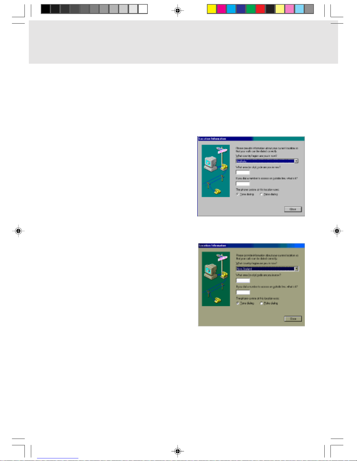
Note: Modem setting in Windows 98
The default modem setting in Windows 98 operating system is United States of America. If you are
residing in Australia or New Zealand, please choose the appropriate country where you are located.
Dial type must be set to Tone Dialing if you are either in Australia or New Zealand.
Please see below instruction for quick modem setup.
A. If you are located in Australia
1. Go to Control panel, select modem icon.
2. Choose Australia in “What country/region
are you in now?”
3. Select Phone system as “Tone Dialing”
4. Close
B. If you are located in New Zealand
1. Go to Control panel, select modem icon.
2. Choose New Zealand in “What country/
region are you in now?”
3. Select Phone system as “Tone Dialing”
4. Close
Ani Content 02/06/00, 19:105
Page 6
Warnings
This manual uses a variety of icons as visual marks so that you can use this computer safely and
correctly and avoid damage and danger to yourself and to others . These icons and their meanings
are as follows. Please learn these icons before reading this manual. Learning these icons will be
useful for understanding this manual.
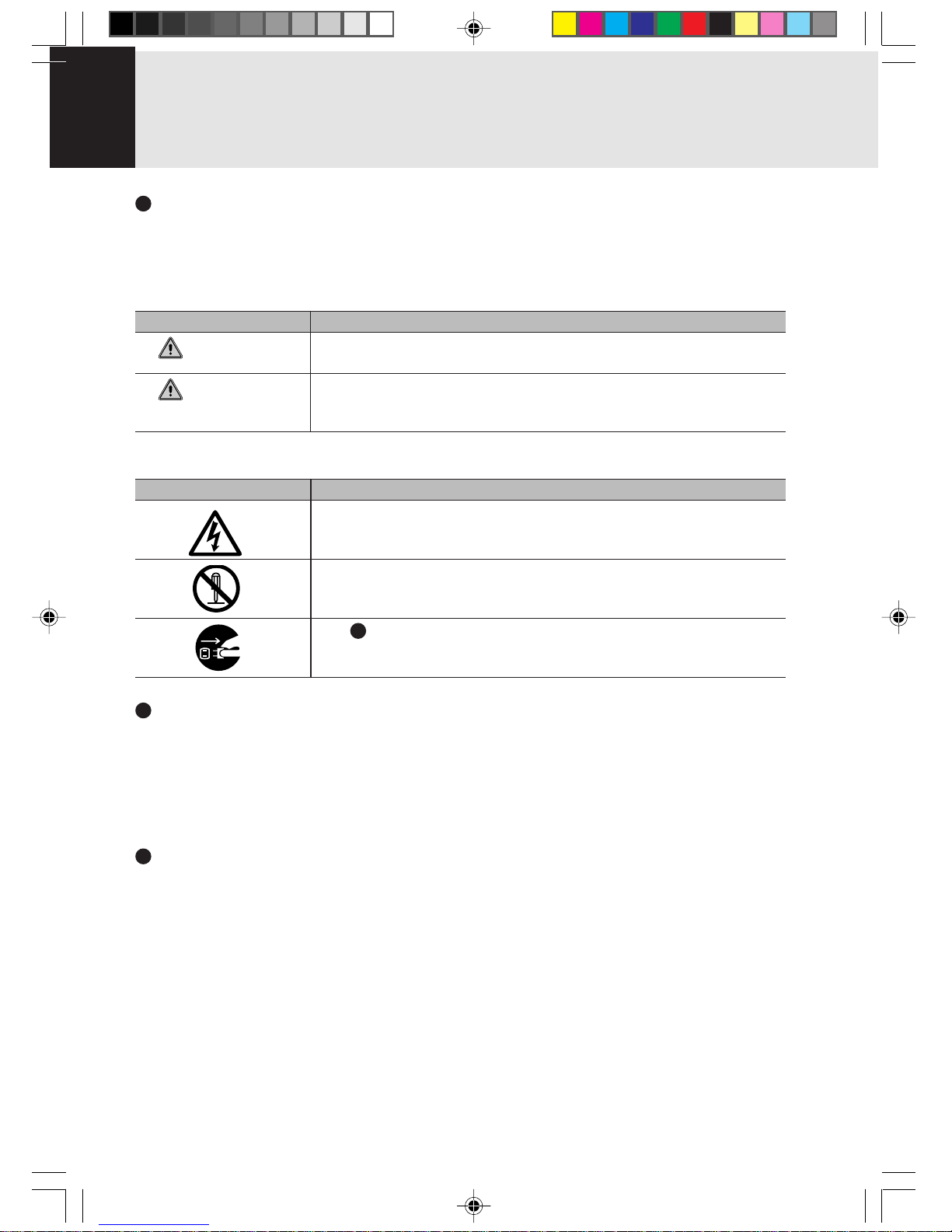
Icon Meaning
Incorrect handling or ignoring this warning can cause a dangerous
situation that could result in death or severe injury.
Incorrect handling or ignoring this warning can cause a dangerous
situation that could result in moderate or minor injury or could result in
equipment damage.
The symbols below are used together with the icons above to indicate what type of danger or
damage is involved.
Symbol Meaning
The ∆ symbol indicates a warning or caution. The symbol inside the ∆
indicates the concrete nature of the warning. (The example on the left
is a caution for electric shock.)
The circle and slash indicates prohibited behavior. The symbol inside
the circle indicates the concrete nature of the prohibition. (The
example on the left indicates that disassembly is prohibited.)
The indicates instructions that must be followed. The symbol inside
indicates the concrete nature of those instructions. (The example on
the left tells you to unplug the power plug from the socket.)
Key notation and operation methods
Explanations of key operations do not show all the characters on the keyboard. Instead they
indicate just the keys necessary to the explanation as follows.
Examples: [Ctrl] key , [Enter] key, [ → ] key
When multiple keys are to be pressed at the same time , this is indicated by connecting them with
[+].
Examples: [Ctrl] + [F3] keys; [Shift] + [ ↑ ] key
Screen examples
The screens shown in this manual are examples. Please understand that the file names and
screens you use may be different.
NOTATION IN THIS DOCUMENT
WARNING
CAUTION
Ani Content 02/06/00, 19:106
Page 7

Critical Points
Column
dir c:
Notation in text
Here is what symbols in text mean.
Symbol Meaning
Indicates a point necessary for correctly operating the hardware or
software.
Gives the meaning and brief explaination of a term.
→ Indicates the page to see elsewhere in this manual.
Command input (key input)
Within the text of this manual, command input (giving commands to the computer by pressing
keys) is indicated as follows.
Example:
↑
In the position indicated in the example above by the ↑, the space left between the characters
indicates that a space needs to be left in the entry by pressing the space bar (the long key with
nothing written on it at the center of the front of the keyboard). Commands are written in this
manual as lowercase latin letters, but uppercase letters may be used.
Product names
The following product names are abbreviated as follows in this manual.
“Microsoft® Windows® 98 operating system” is written as “Windows 98”.
“Microsoft® MS-DOS® operating system Version 6.2/V” is written as “MS-DOS”.
“Microsoft® Windows® operating system Version 3.1” is written as “Windows 3.1”.
“Microsoft® Windows® 2000 operating system” is written as “Windows 2000”.
“Microsoft® Windows NT® Server network operating system V ersion 3.5” and “Microsoft® Windows
NT® Workstation operating system Version 3.5” are both written as “Windows NT 3.5”.
“Microsoft® Windows NT® Server network operating system V ersion 3.51” and “Microsoft® Windows
NT® Workstation and NT Server Version 4.0” are both written as “Windows NT 4.0”.
“Windows NT 3.51” and “Windows NT 4.0” are both written as Windows NT.
“Fujitsu Lifebook” is written as “this computer” or “the computer main unit”.
Ani Content 02/06/00, 19:107
Page 8

Configuration of this Manual
Getting Started
This section explains boot sequence for using this computer.
SECTION 1
This section explains basic operations and basic items for using this computer, including the
names of the parts and their functions, touch pad operation methods, connector box handling,
and battery operation.
SECTION 2
This section explains installation of options for this computer.
SECTION 3
This section explains how to care for your computer.
SECTION 4
This section explains what to do when trouble occurs with this computer and when messages are
displayed. Read this section as the necessity arises.
Ani Content 05/06/00, 11:398
Page 9

CONTENTS
SECTION 1
1. Names of the Parts and their Functions .............................2
Front/Top .............................................................................................2
Left Side/Right Side............................................................................. 4
Rear/Bottom ........................................................................................ 6
Port replicator ......................................................................................8
Status Indicator LCD ........................................................................... 9
2. Flat Point ..............................................................................11
What Is the Flat Point? ......................................................................11
Flat Point Usage ................................................................................ 12
3. Keyboard ..............................................................................13
Keyboard ...........................................................................................13
Numeric Keypad Mode...................................................................... 13
Names of the Main Keys and their Functions.................................... 14
4. Switching on the Power ......................................................16
Switching on the power ..................................................................... 16
5. Switching off the Power......................................................18
Precautions for Switching Off the Power ........................................... 18
Switching Off the Power .................................................................... 18
6. Suspend/Resume Function ................................................20
Suspending ....................................................................................... 20
What Is the Suspend/Resume Function?.......................................... 20
Precautions for Suspending .............................................................. 22
Resuming .......................................................................................... 23
7. Battery ..................................................................................24
Battery Charging ............................................................................... 24
Battery Operation .............................................................................. 25
Checking the Remaining Battery Charge .......................................... 26
Low Battery State .............................................................................. 27
Replacing the Internal Battery Pack .................................................. 28
Precautions for Battery Pack............................................................. 30
8. Port Replicator.....................................................................31
Attaching the port replicator .............................................................. 31
Detaching the port replicator ............................................................. 32
9. Built-in LAN (local-area network) device...........................33
Connection ........................................................................................ 33
10.Internal FAX Modem............................................................34
Connection ........................................................................................ 34
SECTION 2
1. Options.................................................................................36
What is the Options ........................................................................... 36
2. PC Cards ..............................................................................38
Precautions for PC Cards.................................................................. 38
Installing PC Cards............................................................................ 39
Removing PC Cards.......................................................................... 40
Ani Content 02/06/00, 19:109
Page 10

3. Expansion RAM Modules ...................................................42
Installing an Expansion RAM Module................................................42
Removing an Expansion RAM Module..............................................44
4. Multi-bay Unit.......................................................................45
Replacing multi-bay units .................................................................. 45
Precautions on handling or using the multi-bay unit..........................46
Loading/Ejecting disks.......................................................................47
Loading/Ejecting an LS-120 disk....................................................... 49
5. Floppy Disk Unit ..................................................................50
Installing a Floppy Disk Unit .............................................................. 50
Precautions for Floppy Disk Unit ....................................................... 51
Removing a Floppy Disk Unit ............................................................ 52
What is a Floppy Disk?......................................................................53
Precautions on Handling ................................................................... 54
Loading/Ejecting a Floppy Disk ......................................................... 55
Loading..............................................................................................55
Ejecting..............................................................................................55
6. Mouse ...................................................................................56
Using the Mouse ............................................................................... 56
Connecting the Mouse ...................................................................... 56
7. Numeric Keypad ..................................................................58
Connecting a Numeric Keypad..........................................................58
8. CRT Monitor .........................................................................59
Connecting an External CRT Monitor................................................59
9. CCD Camera ........................................................................61
Preparing required things .................................................................. 62
Connecting the CCD camera ............................................................ 62
Using CCD camera ........................................................................... 62
Removing the CCD camera from personal computer........................ 65
10.One Touch Operation buttons ............................................66
SECTION 3
1. Care and Maintenance ..........................................................68
2. Glossary.................................................................................73
SECTION 4
1. When This Happens ............................................................82
Ani Content 02/06/00, 19:1010
Page 11
Getting Started
Starting Your LifeBook
POWER ON
Power Switch
The power switch is used to turn on your notebook from its off state. Once you have connected your
AC adapter or charged the internal Lithium Ion Battery, you can power on your notebook.
CAUTION
When you turn on your notebook be sure you hav e a power source. This means that at least one
battery is installed and charge, or that the AC adapter is connected and has power.
Locate the power switch of y our notebook. The power s witch are located either at the rear , front or on
the side of your notebook.
CAUTION
Do not carry your notebook around with the power on or subject it to shocks or vibration, as y ou
risk damaging your notebook.
When you P ower On your notebook, it will perf orm a Pow er On Self Test (POST) to check the internal
parts and configuration for correct functionality. If a fault is found, your notebook will emit an audio
warning and/or an error message will be displayed. Depending on the nature of the problem, y ou may
be able to continue by starting the operating system or by entering the BIOS setup utility and revising
the settings.
After satisfactory completion of the Po wer On Self Test (POST), your notebook will load your operating
system.
CAUTION
Never turn off your notebook during the Power On Self Test (POST) or it will cause an error
message to be displayed when you turn your notebook on the next time.
BOOT SEQUENCE
The procedure for starting-up your Fujitsu LifeBook notebook is termed the Bootup sequence and
involves your notebook’s BIOS. When your notebook is first turned on, the main system memory is
empty, and it needs to find instructions to start up your notebook. This information is in the BIOS
program. Each time you power up or restart your notebook, it goes through a boot sequence which
displays a Fujitsu logo until your operating system is loaded. During booting, your notebook is
performing a standard boot sequence including a Po wer On Self Test (POST). When the boot sequence
is completed without a failure and without a request for the BIOS Setup Utility, the system displays
the operating system’s opening screen.
The boot sequence is executed when:
• You turn on the power to your notebook.
• You restart your notebook from the Windows Shut Down dialog box.
• The software initiates a system restart. Example: When you install a new application.
• You reset the system by pressing the three keys [CTRL+ALT+DEL].
Ani Get Start 02/06/00, 19:1011
Page 12

BIOS SETUP UTILITY
The BIOS Setup Utility is a program that sets up the operating environment for your notebook. Your
BIOS is set at the factory for normal operating conditions, therefore there is no need to set or change
the BIOS’ environment to operate your notebook.
The BIOS Setup Utility configures:
• Device control feature parameters, such as changing I/O addresses and boot devices.
• System Data Security feature parameters, such as passwords.
Entering the BIOS Setup Utility
To enter the BIOS Setup Utility do the following:
1. Turn on or restart your notebook.
2. Press he [F2] key once the Fujitsu logo appears on the screen. This will open the main menu of
the BIOS Setup Utility with the current settings displayed.
3. Press the [RIGHT ARROW] or [LEFT ARROW] key to scroll through the other setup menus to
review or alter the current settings.
BIOS Guide
A guide to your notebook’s BIOS is available online. Please visit our technical support section at
www.fujitsu-pc-asia.com.Once there, click on the notebook series from the pull down menu and
select the appropriate notebook model.
Ani Get Start 02/06/00, 19:1012
Page 13

11
11
1
11
11
1
SECTIONSECTION
SECTIONSECTION
SECTION
SECTIONSECTION
SECTIONSECTION
SECTION
SECTION 1
Ani Sec 1_01-15 02/06/00, 19:101
Page 14
2
1.
Names of the P arts and their Functions
Front/Top
1
6
7
2
3
9
10
4
5
8
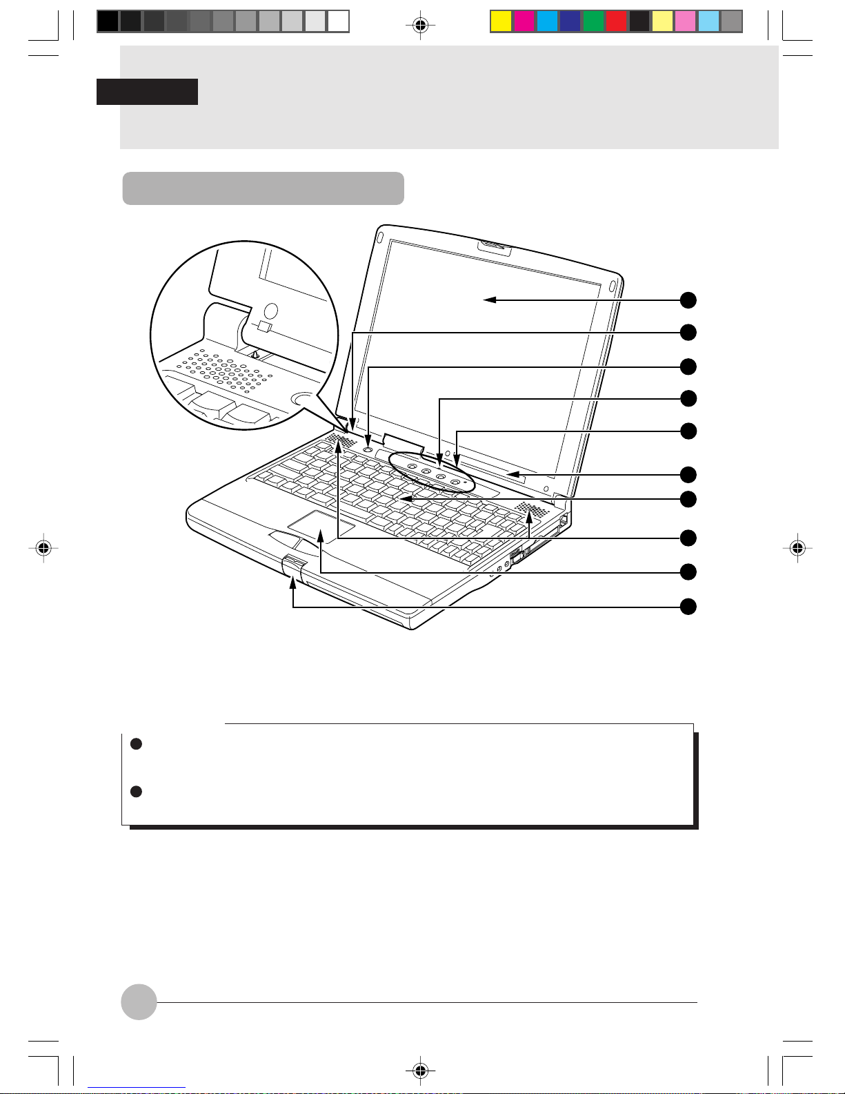
1 LCD panel
Displays text, graphics, etc.
Critical Point
The TFT color LCD panel used with this computer has been made using high resolution
technology, but there might be dots that are always lit up or always not lit up on part of the
screen.
There may be some slight inconsistencies on the LCD panel with variations in temperature.
Please note that this is not a malfunction.
2 Cover close switch
When the LCD panel is closed, this switch turns off the backlight and suspends operation of the
personal computer.
3 Suspend/Resume switch
This switch suspends/resumes the computer main unit. From here on, it is written as SUS/RES
switch.
SECTION 1
Ani Sec 1_01-15 02/06/00, 19:102
Page 15
SECTION 1
3
4 Condenser Microphone
Allows sound (monaural) recording.
Critical Point
When some kind of software (karaoke software , etc.) is activ ated, it automatically inactivates
muting of the built-in microphone and the built-in speaker may resultingly howl. In such the
case, use a general headphone and external speaker available on the market.
When the built-in microphone is used, be sure to hold the LCD panel open, otherwise howling
may be occur.
5 One-touch button
Allows you to start application software or check the arrival of an e-mail.
6 LCD
Displays the status of the computer main unit. See “Status Indicator LCD”.
7 Keyboard
Keys are pressed to give commands to the computer main unit.
8 Speaker
Outputs the sound of the computer main unit.
Critical Point
If the built-in speaker and microphone are used at the same time, it may cause howling. If
howling occurs, adjust the sound volume with the volume control knob and “Volume Control”
on the screen.
9 Flat point
This moves the mouse pointer.
! Latch
This is pressed to release the lock when the LCD panel is opened.
Ani Sec 1_01-15 02/06/00, 19:103
Page 16
4
1211 13
14 15 16 17 18 19 20
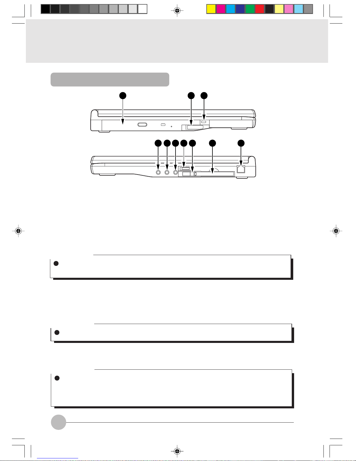
" Multi-bay
Depending on the models, one of the following units is provided for your personal computer.
• CD-ROM drive unit
• CD-R/RW drive unit
• CCD Camera drive unit
• DVD-ROM drive unit
• Super disk drive unit
• PC card drive unit
• Weight saver
# Multi-bay unit release lever
Raise this lever to remove the unit from the multi-bay.
$ Anti-theft lock
Can be connected with a commercially available anti-theft cable.
Critical Point
Do not leave the multi-ba y v acant when using your computer, otherwise your computer might
break down.
Critical Point
The anti-theft lock is for the Kensington Microsaver Security System.
% Headphone jack
For connecting commercially available headphones.
Critical Point
Things that can be fitted to the headphone jack
- Headphones, earphones, amplifier-installed external speakers (mini-plug with 3.5mm outer
diameter. However you may not be able to fit them because of the shape, so check before
inserting.)
Left Side/Right Side
Ani Sec 1_01-15 02/06/00, 19:104
Page 17
SECTION 1
5
& Line In jack
Terminal for audio input.
( Microphone jack (MIC-IN jack)
Terminal for connecting a commercially-available microphone.
Critical Point
When a microphone is in use, excessiv ely turning up the v olume might cause the speaker to
howl.
Some types of commercially-available microphones (for example, dynamic microphones)
cannot be used with this computer.
) Volume control
Adjusts the sound volume. Turning it towards you lowers the volume; turning it away from you
raises it.
~ PC card eject/lock button
Press this button to eject the PC card. When the inserted PC card is locked by this button, it is
protected from accidentally sticking out.
+ PC card slot
Slot (1) for inserting separately sold PC card.
This PC card slot is identified as ZV port, which is connected with the main unit of this personal
computer.
Critical Point
If the volume is raised too high when using a microphone, howling may occur between the
speaker and the microphone.
Critical Point
A dummy card has been inserted in the PC card slot of a new computer.
The ZV port conforms to the PC card standard for high-speed processing of animation and
sound data.
You may be required to use the “slot 0” for “slot 1” depending on the operating system used.
, Modular connector
This is for connecting to the telephone line.
Ani Sec 1_01-15 02/06/00, 19:105
Page 18
6
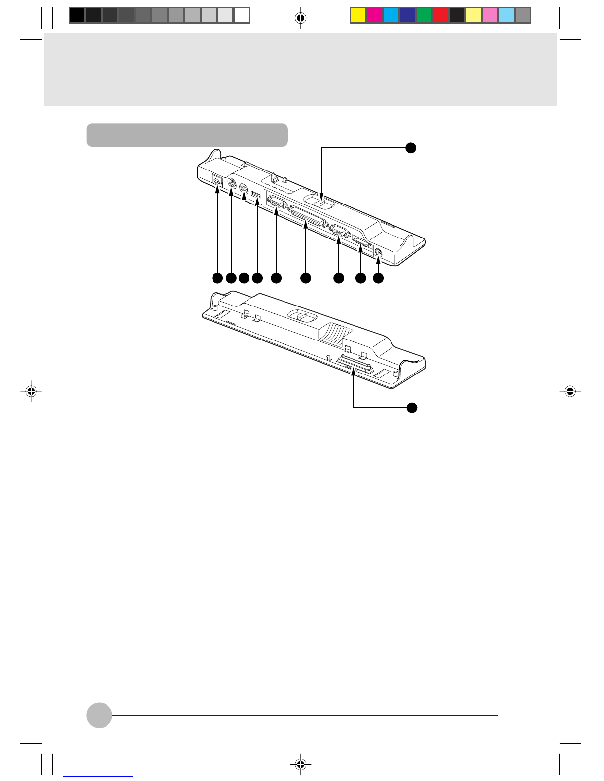
Rear/Bottom
21
22
23
24
25
26
27
29
30
31
32
28
Ani Sec 1_01-15 02/06/00, 19:106
Page 19
SECTION 1
7
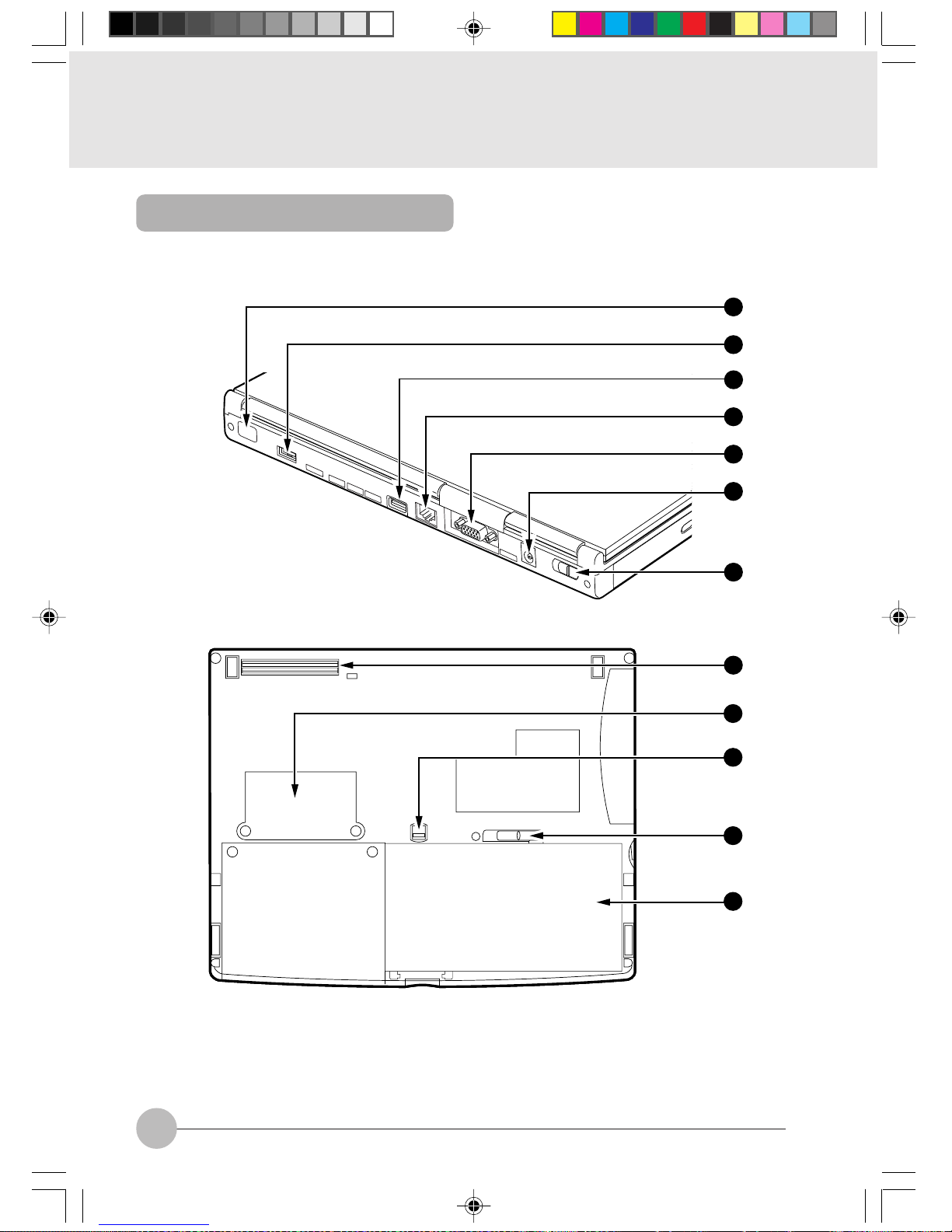
- Infrared communications port
Interface for carrying out infrared communications.
Critical Point
Don’t bring the AC adaptor or CRT display close to the infrared communications port during
infrared communication, otherwise the computer may malfunction because of noise generated.
. mini-Serial connector (available on certain model)
/ USB connector (Invalid for the Windows NT system)
Connector for connecting a peripheral equipment which meets the USB standard.
: LAN connector
Connector for connecting a LAN cable.
; CRT connector
Connector for connecting an external display, for example, a separately sold CRT monitor.
< DC-IN connector
Connector for connecting the AC adaptor that comes with this computer.
= MAIN switch
This is the switch for turning the power to the computer main unit on and off.
> Port replicator connector
Connector for connecting the port replicator.
? Expansion RAM module slot
Slot for fitting a separately sold expansion RAM module.
@ Release button
Slide this release button to release the internal battery pack lock from locking status.
[ Internal battery pack lock
Slide this lock to attach/detach the internal battery pack to/from this personal computer.
\ Internal battery pack
The internal battery pack is mounted here.
Ani Sec 1_01-15 02/06/00, 19:107
Page 20
8
1
52 3 4 6 8 9 107
11
1 Port replicator release button
Slide this button to remove the port replicater
from the personal computer.
2 LAN connector
Connector for connecting a LAN cable.
3 Expansion keyboard connector
Connector for connecting a separately sold PS/2 standard numeric keypad.
4 Mouse connector
Connector for connecting a separately sold PS/2 mouse.
5 USB connector (Invalid for the Windows NT system)
Connector for connecting a peripheral equipment which meets the USB standard.
6 CRT connector
Connector for connecting a separately sold CRT monitor.
7 Parallel connector
Connector for connecting a separately sold printer.
8 Serial connector
Connector for connecting an optional equipment of the RS-232C interface standard.
9 FDD unit connector
Connector for connecting a separately sold floppy disk unit.
! DC-IN connector
Connector for connecting the AC adaptor that comes with this computer.
" Connector
Connector for connecting the port replicater.
Port replicator
Ani Sec 1_01-15 02/06/00, 19:108
Page 21
SECTION 1
9
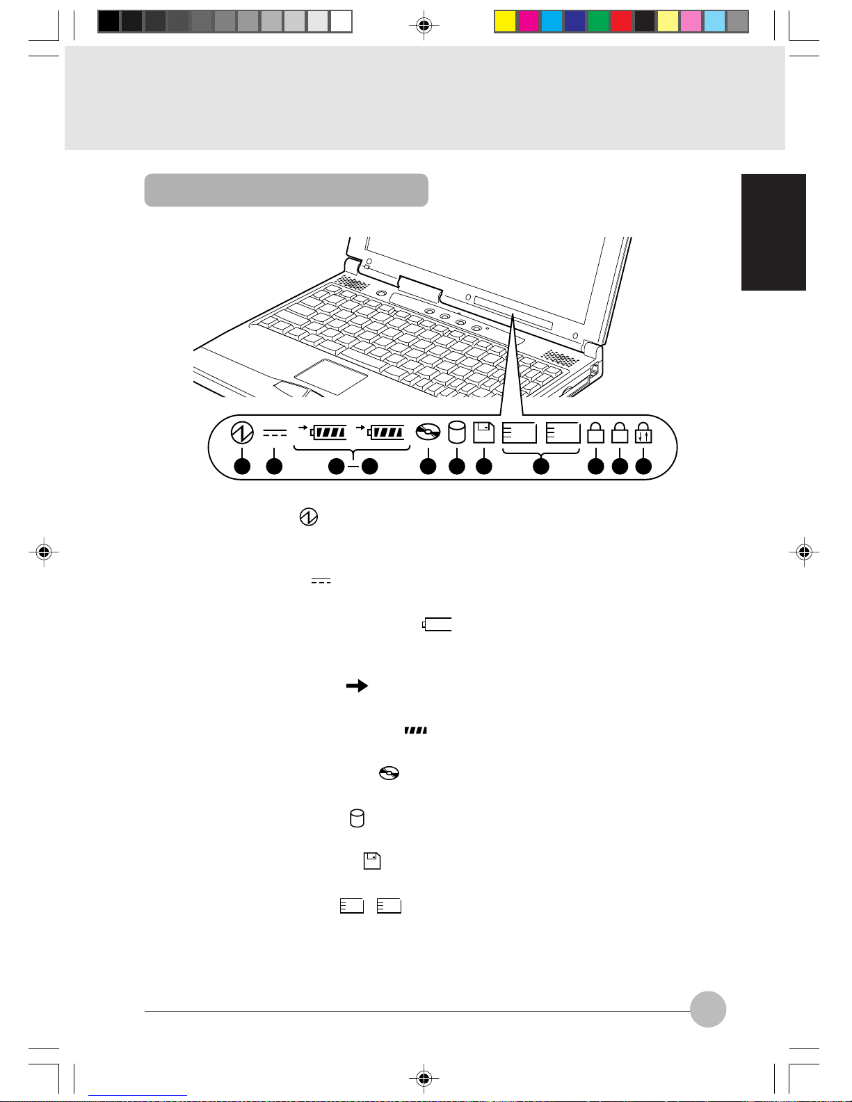
1 SUS/RES indicator ( )
When this computer is operating, this indicator lights up; when the computer is in suspend mode,
this indicator flashes.
2 AC adaptor indicator ( )
Lights up when the power is being supplied from the AC adaptor.
3 Battery pack mounting indicators ( 1, 2, )
Lights up when the battery pack is mounted. The number 1 refers to the b uilt-in battery pack and
the number 2 refers to the expanded battery pack.
4 Battery charging indicator ( )
Lights up when the battery is charging; flashes when the battery is too hot or cold to charge.
5 Remaining battery charge indicator ( )
Displays the amount of charge remaining in the corresponding battery.
6 CD-ROM drive access indicator ( )
Lights up while data is being read from the CD-ROM or the DVD-ROM.
7 Hard disk access indicator ( )
Lights up while the internal hard disk or the 2nd hard disk is being accessed.
8 Floppy disk access indicator ( )
Lights up while data is being read/written on the floppy disk or the LS-120 disk.
9 PC card access indicator (
1 2
)
Lights up while the PC card in the corresponding PC card slot is being accessed.
The indicator 1 corresponds to the built-in PC card slot, while the indicator 2 corresponds to the
PC card drive unit mounted in the multi-bay.
1
1
2
A
1
1 2 11 12
3
5
2
8 9 1076
Status Indicator LCD
Ani Sec 1_01-15 02/06/00, 19:109
Page 22
10
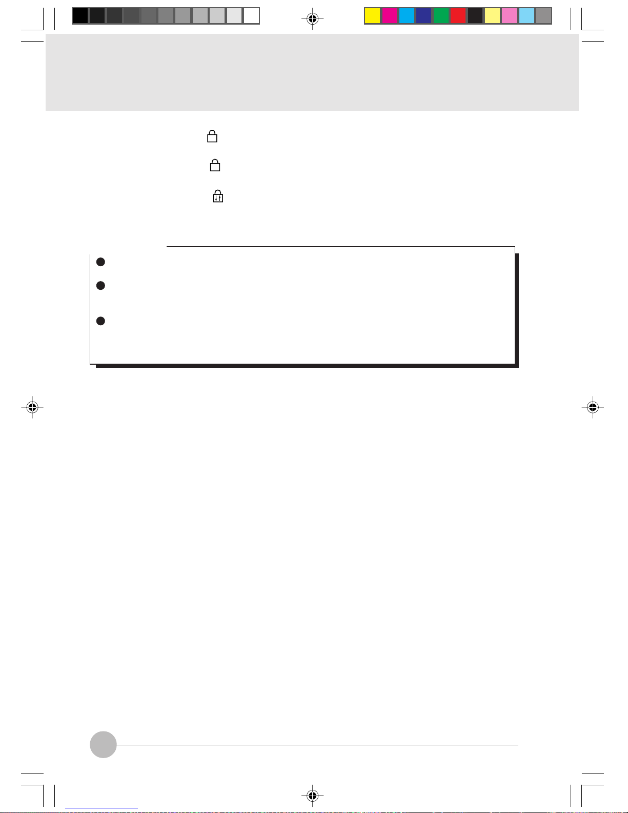
! Num Lock indicator (
1
)
Lights up when [Num Lk] key is pressed to put the keyboard into numeric keypad mode.
" Caps Lock indicator (
A
)
Lights up when [Shift] + [Caps lock] keys are pressed to put the keyboard into CAPS mode.
# Scroll Lock indicator ( )
Lights up or goes out each time the [Fn] + [Scr Lk] keys are pressed.
Critical Point
If you turn off the main switch or operate the SUS/RES button while the hard disk access
indicator or floppy disk access indicator is lit, the data being accessed may be destroyed.
When the main switch is switched off, all the indicators other than charging go off. However,
the AC adaptor lamp comes on regardless of the status indicator lamp when power is being
supplied.
When you use Windows 98, if the CD automatic insertion function is enabled, the system
periodically checks for a CD. Therefore, the CD-ROM drive access indicator on the status
indicator LCD lights up periodically.
Ani Sec 1_01-15 02/06/00, 19:1010
Page 23
SECTION 1
11
2. Flat Point
The main operations for this computer use the flat point. This item explains the flat point.
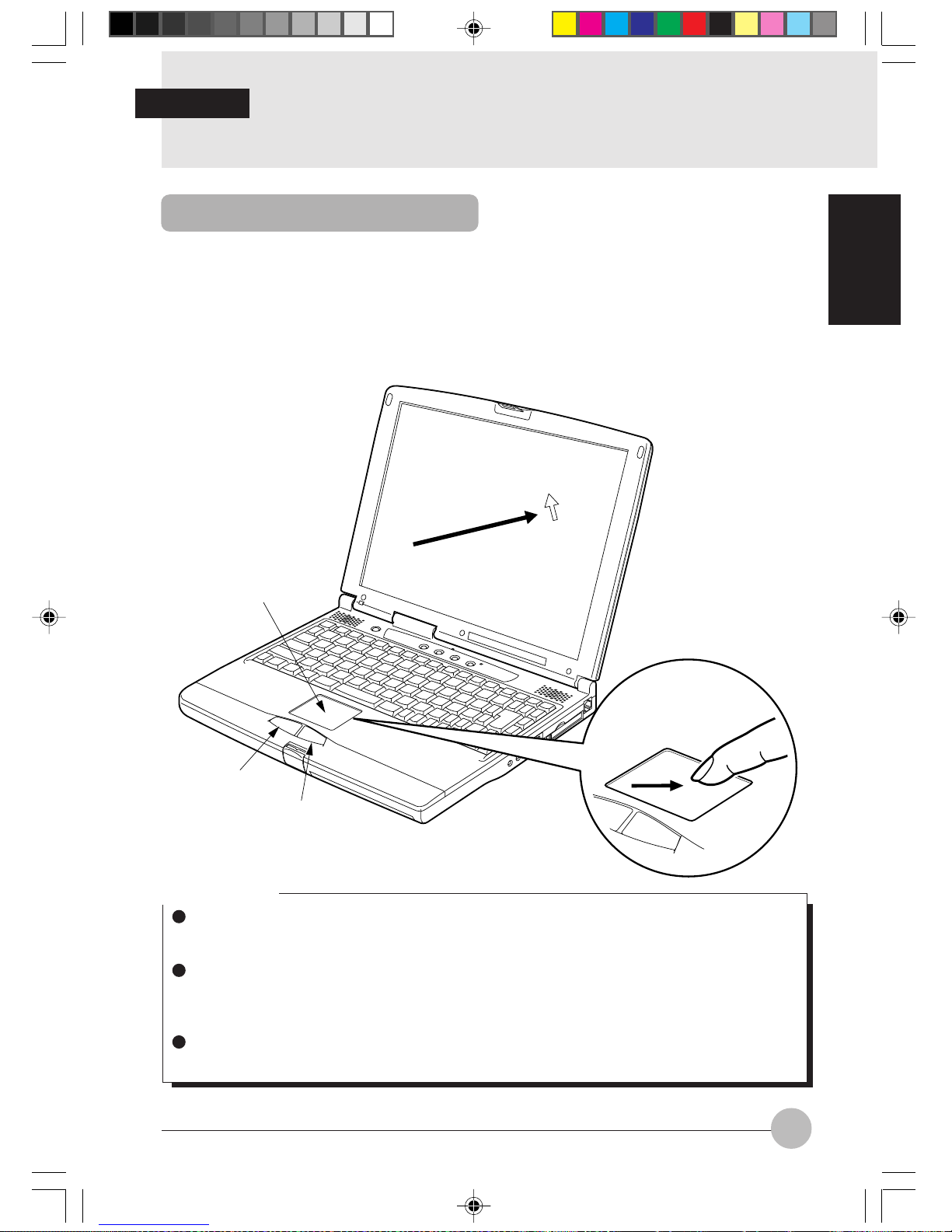
The flat point is a convenient pointing device that moves the mouse pointer with your fingertips. It
comprises the operating surface and the two buttons in front of it. The operating surface has the
same function as the ball section of a mouse. Y ou mo v e the mouse pointer on the screen by moving
your fingertip up, down, left, and right along the operating surface. You can also carry out such
operations as clicking, double clicking, pointing, and dragging by tapping lightly on the operating
surface. The left and right buttons correspond to the buttons the mouse. Their functions depend on
the application software.
Operating surface
Left button
Right button
Critical Point
There is a slight difference in a result of pointing operation among operators because of the
operation principle of the flat point. Given an example, pointing operation is influenced by
moisture of the operator’ s fingertips (dry or wet fingers).
If the operating surface is dirty or moist because of high humidity , etc., it may cause malfunction
of the operating surface. If it occurs, wipe down the operating surface with dry soft cloth to
remove the moisture and dirt. If the operating surface is badly soiled, wipe out the dirt with soft
cloth moistened with a neutral detergent thinned with water.
When you intend to use an optional mouse, access the “Keyboard/Mouse Setting” menu of
the “BIOS Setup” and set items necessary for operating the mouse together with the flat point.
SECTION 1
What Is the Flat Point?
Ani Sec 1_01-15 02/06/00, 19:1011
Page 24

12
Flat Point Usage
Click Either tap the operating surface once or press the
left button once until it clicks, then immediately
release it. Clic king the right button once is called
a right click.
Double click Either tap the operating surface twice consecu-
tively or twice quickly press the left button twice
until it clicks, then immediately release it.
Point Align the mouse pointer with a menu item or the
like. If there is a level beneath the manual item
on which you placed the mouse pointer (if > is
displayed at the right end of the menu item), that
menu is displayed.
Drag Move the mouse pointer to any position, then
quickly tap the operating surface twice . After the
second tap, do not remov e your fingertip from the
operating surface, b ut drag it along the oper ating
surface to the desired position, then remove y our
finger from the operating surface.
Critical Point
You can also carry out the click and drag operations in combination with the buttons.
Tap gently and quickly with your fingertips. There is no need for much force.
When you are moving the mouse pointer with the flat point, if you lift up your fingertip and
bring it back down to a different point on the operating surface, the mouse pointer on the
screen does not move. If y ou drag your fingertip along the operating surface from the position
where you brought it back down, the mouse pointer on the screen moves in the direction in
which you drag your fingertip.
The interval between taps for double clic king can be adjusted with Mouse in the Control Panel
for Windows 98.
Ani Sec 1_01-15 02/06/00, 19:1012
Page 25
SECTION 1
13
3. Keyboard
The keyboard is the de vice for giving instructions to the computer , inputting data, and e xecuting. The
keys can be divided into two types.
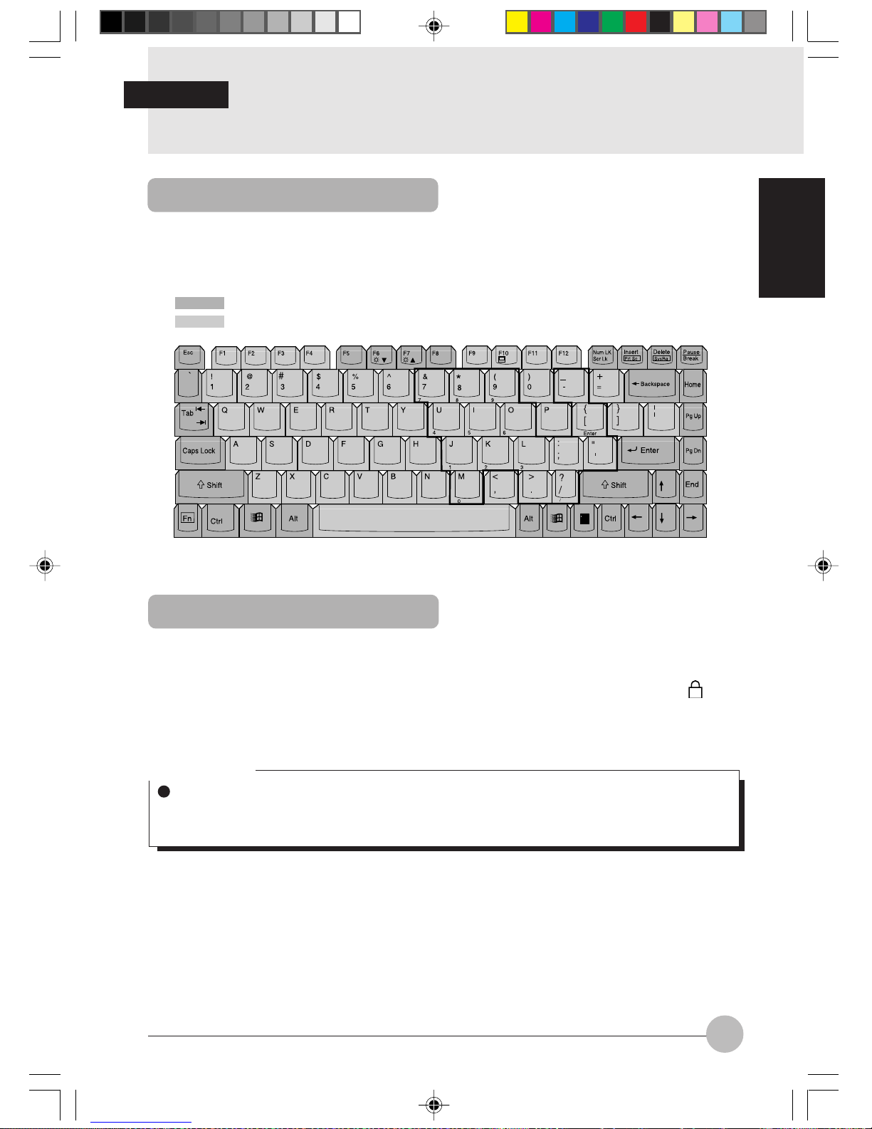
Numeric Keypad Mode
The mode in which some of the character keys are used as numeric keys (with a key layout that
makes numeric input easier) instead of their normal functions is called numeric keypad mode. The
keyboard is switched to numeric keypad mode with [Num Lk]. (In numeric keypad mode, 1 is displayed on the status indicator LCD.) The keys surrounded by thick lines in the diagram above become the numeric keypad. The numbers input with these keys are printed in front of each key.
Critical Point
When the separately sold numeric keypad is connected, if you press [Num Lk] to put the
computer into numeric keypad mode, the keys on the external numeric keypad are enabled,
but the numeric keypad section on the keyboard is disabled.
SECTION 1
Control keys
Character keys
Keyboard
Ani Sec 1_01-15 02/06/00, 19:1013
Page 26

14
Names of the Main Keys and their Functions
Esc (escape) key
The usage is determined by the application software. It is often used to return to the previous
operation.
F1-F12 (function) keys
The usage depends on the application software.
Fn key
A key unique to this computer; it has the following functions.
[Fn] + [F3] This switches ON/OFF of the speaker.
When a pip sounds with this operation, the speaker is on. When nothing
sounds, the speaker is turned off.
[Fn] + [F5] This selects whether or not to use the entire LCD screen for display in text
mode.
[Fn] + [F6] Turns down the backlight of the LCD.
[Fn] + [F7] Turns up the backlight of the LCD.
[Fn] + [F10] Rotates among the three display options: LCD only, CRT only, both LCD
and CRT.
[Fn]+SUS/RES switch
Activates the Save To Disk function.
Space key Inputs a single space character.
(This is the long key with nothing written on it at the center of the front of the
keyboard.)
[↑][↓][←][→] (cursor) keys
Move the cursor.
Critical Point
Luminance of the backlight of the LCD can be turned up (with [Fn] + [F7] keys) or turned
down (with [Fn] + [F6] keys) in three degrees.
Ani Sec 1_01-15 02/06/00, 19:1014
Page 27

SECTION 1
15
Enter key
Also called the return key or the line feed ke y . This k ey inputs line feeds and ex ecutes command.
Ctrl key
Used in combination with other keys; its functions depend on the application software.
Shift key
Used in combination with other keys.
Alt key
Used in combination with other keys; its functions depend on the application software.
Caps Lock key
To lock the ke yboard into caps mode, press this k ey together with the Shift k e y. Pressing this
key again ends caps mode.
Num Lk (numerical lock) key
Press this key to put the computer into numeric keypad mode.
Scr Lk (scroll lock) key
Its functions depend on the application software.
Print Screen key
Press this key to make a hard copy of the screen.
Pause key
Press this key to pause the screen display.
Break key
Its functions depend on the application software.
Insert key
Press this key to insert a new character between characters . The ne w characters are entered
at the cursor position.
Delete key
Press this key to delete a character . Pressing the Delete key and the Ctrl and Alt keys at the
same time resets this computer.
Home key
Press this key to mov e the cursor directly to the head of the row or the head of the document.
End key
Press this key to move the cursor directly to the end of the row or the end of the document.
Pg Up key
Press this key to switch to the previous screen.
Pg Dn key
Press this key to switch to the next screen.
Back Space key
Press this key to delete the character to the left of the cursor position.
Sys Rq (system request) key
When this key is supported by the application software, this k ey is used f or such functions as
resetting the keyboard. Press this key together with the Alt key.
[ ] (Windows) key (only valid for Windows 98)
Press this key to display the Start menu.
[ ] (Application) key (only valid for Windows 98)
Press this key to displa y the shortcut menu for the selected item. This k ey has the same role
as the mouse right click.
Ani Sec 1_01-15 02/06/00, 19:1015
Page 28

16
4. Switching on the Power
Switching on the power
This item explains the normal way to switch the computer main unit power on.
Critical Point
When turning on the personal computer connected with an optional FDD unit, check to see
whether a floppy disk is set in the floppy disk drive or not. If there is a floppy disk set in the
drive, be sure to remove it before turning on the computer.
1 Connect the AC adaptor.
First connect the AC power cord to the AC
adaptor (1), next connect the other cord of
the AC adaptor to the personal computer’ s DCIN connector (2). Lastly, plug the AC power
cord into an AC outlet (3).
1
2
3
AC adaptor
2 Open the LCD panel.
Push the latch to release the lock, then lift the
display panel with your hand.
Latch
3 Switch on the main switch of the
computer main unit.
Power is supplied from the AC adaptor, the
power comes on, and the POST starts. Also,
the etc. on the status indicator LCD are
displayed.
Main switch
SECTION 1
Ani Sec 1_16-30 02/06/00, 19:1116
Page 29
SECTION 1
17
Critical Point
Do not carry this computer around or subject it to shock or vibration with the power on. These
can result in breakdown.
Column
POST is the abbreviation for POWER ON SELF TEST, which is a self-diagnostic test that
checks for abnormalities within the computer . This test is automatically carried out when the
power is switched on f or this computer . If the power is switched off during the POST, an error
message is displayed the next time the computer is started up. Do not cut off the power
during the POST.
Ani Sec 1_16-30 02/06/00, 19:1117
Page 30

18
5. Switching off the Power
This item explains how to switch off the power and gives precautions for switching off the
power.
Precautions for Switching Off the Power
The following precautions must be observed when switching off the power.
When switching off the main switch, end Windows 98 first.
When the main switch is switched off, if the suspend mode is suspend, the suspend function
stops working. If the application softw are has been suspended during execution, it is necessary
to save the data, then end the application software.
After you switch off the main switch, wait at least about ten seconds before switching it back
on again.
1 Click the Start button.
The Start menu is displayed.
2 Click Shut Down.
The following message is displayed.
SECTION 1
Switching Off the Power
Ani Sec 1_16-30 02/06/00, 19:1118
Page 31

SECTION 1
19
3 Check that Shut down the computer is selected, then click Yes.
The power is switched off.
Critical Point
If the MAIN switch is not turned off after the step 3, the computer will be turned on next time
by pressing the SUS/RES switch only.
You can reset this computer by selecting Restart the computer with the screen shown in Step
2. Resetting means that the data in memory is all erased and the operating system is loaded
again from the hard disk or a floppy disk.
4 Switch off the main switch.
Slide the main switch in the direction of the
arrow ( side). The status indication LCD
indicator goes out and the power for the
computer main unit is cut off.
Main switch
Critical Point
If the computer will be unused for a long period, remove any CD-ROM or floppy disk and
disconnect the AC adaptor.
Ani Sec 1_16-30 02/06/00, 19:1119
Page 32

20
6. Suspend/Resume Function
What Is the Suspend/Resume Function?
When this computer is suspended with the SUS/RES switch, the suspend/resume function retains
the programs and data in memory as is so that you can resume operations immediately the next time
you press the SUS/RES switch.
Critical Point
Which of the two destinations suspending saves the data in the computer to depends on the
BIOS setup Power menu setting as follows.
System RAM:
When “Suspend” is set with the BIOS setup Power menu Suspend Mode item, the
data is saved to system RAM. Power for the system RAM is supplied from the AC
power supply if the AC adaptor is connected or from the battery if the AC adaptor is
not connected.
Save to Disk area:
If “Sav e to Disk” is set with the BIOS setup P o wer menu Suspend Mode item, the data
is written to the Save to Disk area on the hard disk.
If you hold down the Fn key while pressing the SUS/RES s witch, the data is sa ved to the hard
disk regardless of the Power menu setting.
There are three ways to suspend this computer, using the SUS/RES switch, Cov er close switch and
for Windows 98, using the Start menu.
Using the SUS/RES switch
1 Suspending
Check that and are out. When you
press the SUS/RES switch, if the BIOS setup
suspend mode is suspend, flashes and
the computer goes into suspend mode.
SUS/RES switch
SECTION 1
Suspending
Ani Sec 1_16-30 02/06/00, 19:1120
Page 33

SECTION 1
21
Using the cover close switch
1 Close the LCD panel.
This unit goes into suspend mode using
the cover close switch.
Critical Point
When the BIOS setup Lid Closure Suspend setting is “Disabled”, this unit does not go into
suspend mode even if you close the LCD panel.
Use the [Quit Windows] dialog.
1 Click the [START] button and then click the [Quit Windows].
The [Quit Windows] dialog appears on the display.
2 Click Standby.
This computer is suspended.
Critical Point
The computer may not be suspended in the following cases.
• When the operating system is activated.
• When any of device drivers is incorrectly installed.
It takes a considerable time to suspend the computer depending on its operating condition.
If the BIOS setup Suspend Mode setting is “Suspend”, suspend mode is ended in the f ollowing
cases. Save important data to a floppy disk or the hard disk.
• The main switch is switched off.
• In battery operation, the battery runs out.
(The battery is still used in suspend mode.)
If you start with the internal battery fully charged, suspend mode lasts about three days
maximum with the AC adaptor not connected.
• When “Use” is selected f or “Resume by modem incoming” on the “P ower Sa vings” menu of
the BIOS setup.
• When “Restore the computer to the original status with a telephone call” is effectively set
by the tab of “Others” of the Windows 98 “PMSet98 properties” window.
Ani Sec 1_16-30 02/06/00, 19:1121
Page 34

22
Precautions for Suspending
Pay attention to the following points when using the suspend function.
Don’t continue pressing the SUS/RES switch for 4 seconds or more. If the SUS/RES switch is
continuously pressed for 4 seconds or longer, the personal computer is turned off.
When the computer is connected to a network using a LAN card or modem and when the peripheral
equipment is expanded with a PC card, you ma y not be ab le to use the suspend/resume function.
When you have expanded functions with a PC card, also check the manual for the cards you are
using.
Do not operate the SUS/RES switch when using Windows NT.
In the following cases, do not use the suspend function, but switch on/off the computer main unit
power supply with the main switch.
• When this computer is unused for a long period
When this computer will be unused longer than the effective period (about three days
maximum) for battery power for suspend mode , save all data, close Windows 98, then s witch
off the main switch. If y ou suspend with the BIOS setup Suspend Mode set to Sa v e to Disk,
the power goes off with the main switch still on. In this case, it does not matter if you switch
off the main switch. The next time you switch on the main switch, operation resumes.
• When installing or removing options
There are some options that can be installed without switching off the main switch. See
SECTION 2 of this manual and the manual that comes with the option product.
In the suspend/resume operation, the screen may flick er for an instant depending on the situation.
Ani Sec 1_16-30 02/06/00, 19:1122
Page 35

SECTION 1
23
Resuming
This personal computer can be resumed by the SUS/RES switch or the cover close switch.
Critical Point
When resuming this personal computer after it was suspended, resume it 10 or more seconds
after the last suspending operation.
The screen occasionally flickers during suspending/resuming operation.
Resuming with the SUS/RES switch
1 Press the SUS/RES switch for
resuming the personal computer.
As the SUS/RES switch is pressed, the
mark of the status indicator LCD stops
blinking and continues lighting. This
indicates that the personal computer is
in the operating status.
SUS/RES switch
Resuming with the cover close switch
1 Fold out the LCD display.
The personal computer is resumed by the
cover close switch.
Latch
Critical Point
When the Lid Open Resume of the BIOS setup is set to “Disabled”, the personal computer
won’t be resumed by folding out the LCD display.
Ani Sec 1_16-30 02/06/00, 19:1123
Page 36

24
7. Battery
For portability, this computer can operate either from the A C adaptor or from its battery. This
item explains how to charge the battery.
1 Connect the AC adaptor.
First connect the AC power cord to the AC
adaptor (1), next connect the other cord of
the AC adaptor to the personal computer’s
DC-IN connector (2). Lastly, plug the AC
power cord into an AC outlet (3).
AC adaptor
2 is displayed.
During charging, is displayed on the
status indicator LCD and the remaining battery
charge is displayed.
Relationship between computer modes and battery charging time
Main switch Computer mode Charging mode Charging time
Operating mode Standard charging About 10 hours
Suspend mode
Stopped
ON
OFF
Quick charge About 4 hours
Critical Point
When the battery charging indicator ( ) goes out and the remaining battery charge indicator
at the leftmost end changes its mode from blinking ( ) to continuous lighting
( ), charging the battery is complete.
Spend a considerable time for charging the battery so that it is charged to the full.
If the ambient temperature is too low, the battery declines in its charging performance.
If the battery is charged just after it was used, charging may result in failure because the
battery temperature has risen and the battery protection function is activated. In such the
case, let the battery remaining in the charging status and charging will start as the batter y
temperature drops.
SECTION 1
1
2
3
Battery Charging
Ani Sec 1_16-30 02/06/00, 19:1124
Page 37

SECTION 1
25
Battery Operation
This item explains operation with the battery.
1 Disconnect the AC adaptor and
switch on the main switch.
Slide the main switch in the direction of the
arrow ( side).
is displayed.
Main switch
2 When the MAIN switch is on, press
the SUS/RES switch.
stops flashing and stays lit up.
SUS/RES switch
Critical Point
When the ambient temperature is lower, the battery operating time is reduced.
With this computer, the battery operating time depends on the conditions under which the
battery is used. However, the operating time of a new, fully-charged battery is about 2-3
hours*.
* : About 4-6 hours when an extension battery pack is installed.
Condition: No optional equipment is connected with the computer and the po wer saving function
is activated by the BIOS Setup menu, etc. (the abov e-mentioned operation hours of the battery
is just a standard, and it varies depending on the operating condition).
Ani Sec 1_16-30 05/06/00, 11:4125
Page 38

26
Checking the Remaining Battery Charge
This computer indicates the amount of battery charge remaining with the remaining battery
charge indicator on the status indicator LCD.
Remaining battery charge indicator
Indicates battery charge level of about 76% to about 100%
Indicates battery charge level of about 51% to about 75%
Indicates battery charge level of about 26% to about 50%
Indicates battery charge level of about 16% to about 25%
Indicates the low battery state (battery charge level of about 15% or lower). The warning
beeps and flashes.
Indicates that the battery has run out (0% charge level).
Critical Point
Indication of the remaining battery charge indicator ( ) may be slightly different from the
real remaining charge rate depending on the operating environment (temperature , number of
times that the battery was previously charged and discharged, etc.) because of the
characteristic of the battery (lithium ionic battery).
When there is 90% or more of the battery capacity remaining in the battery after the AC
adapter is disconnected, the battery won’t be charged. Charging the battery starts when its
remaining power drops to 89 % or less of the capacity.
Battery abnormality indicator
Indicates that the battery can not be charged normally.
Critical Point
When is displayed, take out the battery pack and re-install it. If this displa y still remains,
the battery pack is abnormal, so replace it.
Ani Sec 1_16-30 02/06/00, 19:1126
Page 39

SECTION 1
27
Low Battery State
This item explains the display when this computer’s battery is low and what to do.
1 The low battery is announced in the following way.
The warning beeps and the battery mark on the status indicator LCD flashes.
Critical Point
If the audio volume is set too low, you may not be able to hear the warning beep.
2 Press the SUS/RES switch.
When the battery goes low, quickly press the SUS/RES switch to suspend operation. Since
the suspend/resume function works even if the computer is suspended during operation, the
program and data are not lost.
Critical Point
If you want to resume operation immediately, connect the AC adaptor, then press the SUS/
RES switch again.
3 Charge the battery.
Connect the AC adaptor to charge the battery.
Critical Point
Reading from and writing to the hard disk uses large amounts of power. When sa ving data to
the hard disk with the battery low, connect the AC adaptor.
If you leave this computer running with the battery low, it is suspended automatically. However , if data is being read from or written to the hard disk or other media, the suspending waits
until that processing is complete.
If you continue using the computer with the battery low, in the worst case, the data being
created or saved may be lost. Quickly connect the AC adaptor.
Ani Sec 1_16-30 02/06/00, 19:1127
Page 40

28
Replacing the Internal Battery Pack
Save the program to the hard disk or a flopp y disk before replacing the Built-in battery pack.
This item explains how to replace the Built-in battery pack.
1 Turn the main switch off and
disconnect the AC adaptor.
Slide the main switch in the direction of the
arrow (to the side).
Disconnect the AC adaptor from the computer main unit.
Main switch
2 Unlock the Built-in battery pack.
Slide the release button located on the bottom
of the main unit (1) and slide the Built-in
battery pack lock (2) for unlocking.
2
1
Release
button
3 Take out the Built-in battery pack.
Remove the Built-in battery pack while putting
fingers on the slit.
W ARNING
ELECTRIC SHOCK
Always turn off the computer main unit main switch and disconnect the AC adaptor
before installing/removing the Built-in battery pack in order to avoid electric shock.
Built-in battery
pack lock
Ani Sec 1_16-30 02/06/00, 19:1128
Page 41

SECTION 1
29
4 Install the new Built-in battery pack.
Install the new Built-in battery pack.
5 Lock the Built-in battery pack.
Lock the Built-in battery pack with the Built-in
battery pack lock that was once released in
the previous step 2.
Built-in battery pack lock
Critical Point
Do not remove the Built-in battery pack except when its service life has expired.
Ani Sec 1_16-30 02/06/00, 19:1129
Page 42

30
Discharge
After you charge the battery pack, even if you store it without using it, over about 1 month it will
naturally discharge.
When the computer won’t be used for a considerably long time (for one month or more), remove
the battery pack from the computer and keep it in a cool place. If the computer is left with the
battery pack set inside, the battery overdischarges and its service life is shortened.
Service life
• The battery pack is a consumption item. After you use it f or a long time , its charging capacity
drops.
• Replace the battery after about 300 to 500 charge/discharge cycles.
• When the battery operating time becomes extremely short, the battery has reached the end of
its service life.
To extend the battery operating time
Use the BIOS setup Power menu.
Conditions under which the battery operating time becomes shorter
• The battery operating time is influenced by the environmental temperature and the battery
operating time can be short at low temperature (5°C).
• If the battery is used for a considerably long time, it deteriorates in the charging capacity
and charging performance. When the internal battery falls into such the condition, replace it
with a new one.
Use the AC adaptor in the following cases
• When using the hard disk, CD-ROM or DVD-ROM, etc. frequently
• When using a LAN or a Modem
Precautions for Battery Pack
W ARNING
ELECTRIC SHOCK
All battery packs are extremely delicate products. When installing or removing one , do
not drop it or subject it to strong shocks. If this should happen, do not use that battery
pack in the interest of safely, because there is a risk of electric shock or malfunction.
Ani Sec 1_16-30 02/06/00, 19:1130
Page 43

SECTION 1
31
8. Port Replicator
Attaching the port replicator
This item explains how to attach the port replicator.
1 Attach the port replicator to your personal computer.
Connector
Align the port replicator connector on the lower surface of your personal computer with the
connector on top of the port replicator, then push down the computer to connect it securely.
SECTION 1
W ARNING
ELECTRIC SHOCK
Always turn off the computer main unit main switch and disconnect the AC adapter
before attaching the port replicator in order to avoid electric shock.
Important
Do not carry your personal computer with the port replicator attached to it, otherwise
the port replicator might fall off and break.
Ani Sec 1_31-34 02/06/00, 19:1131
Page 44

32
2 Detach the port replicator from your
personal computer.
Lift up the personal computer to detach it from
the port replicator.
This item explains how to detach the port replicator.
W ARNING
ELECTRIC SHOCK
Always turn off the computer main unit main switch and disconnect the AC adapter
before detaching the port replicator in order to avoid electric shock.
Detaching the port replicator
1 Release the lock.
Slide the port replicator release button to the
right to release the lock.
Ani Sec 1_31-34 02/06/00, 19:1132
Page 45

SECTION 1
33
9. Built-in LAN (local-area network) device
This item explains how to connect a LAN cable into the LAN connector.
Connection
1 Turn off the computer and disconnect the AC adaptor from it.
2 Plug a LAN cable into the LAN connector on your personal computer or port replicator to
connect it to a network.
Critical Point
To unplug the LAN cable from the LAN connector, pull the jack
while holding down the clip. Failure to do so might damage the
jack, cable or connector.
Y our computer consumes more electric energy when it is connected
to a LAN. When using a LAN, therefore, it is advisable to use the
AC adaptor to supply power to your computer.
SECTION 1
W ARNING
ELECTRIC SHOCK
Be sure to turn off your personal computer and disconnect the AC adaptor from it before connecting a LAN cable to the computer , otherwise you might get an electric shock.
ELECTRIC SHOCK
When it thunders in the neighborhood, immediately turn off your personal computer
and disconnect the AC adaptor and the LAN cable from it, otherwise your computer
might be struck and broken by lightening and thus cause a fire.
CAUTION
ELECTRIC SHOCK
Do not touch the LAN connector with your finger, otherwise you might get an electric
shock.
Ani Sec 1_31-34 02/06/00, 19:1133
Page 46

34
10.Internal FAX Modem
This item explains how to plug a modular cable into the modular connector.
1 Turn off the computer and disconnect
the AC adaptor from it.
2 Using a modular cable, connect the
computer to the telephone line.
Critical Point
To disconnect the modular cable from the connector, pull the jack
while holding down the clip. Failure to do so might damage the
jack, cable or connector.
Your computer consumes more electric energy when using the
built-in modem. When using the modem, therefore, it is advisab le
to use the AC adaptor to supply power to your computer.
SECTION 1
CAUTION
ELECTRIC SHOCK
Do not touch the modular connector with your finger , otherwise you might get an electric shock.
W ARNING
ELECTRIC SHOCK
Be sure to turn off your personal computer and disconnect the AC adaptor from it before
connecting a modular cable to the computer , otherwise you might get an electric shock.
ELECTRIC SHOCK
When it thunders in the neighborhood, immediately turn off your personal computer
and disconnect the AC adaptor and the modular cable from the computer, otherwise
your computer might be struck and broken by lightening and thus cause a fire.
Connection
CAUTION
The internal modem is not intended for use with Digital PBX systems. Do not connect
the internal modem to a digital PBX as it may cause serious damage to the internal
modem or your entire notebook.
Consult your PBX manufacturer’s documentation for details. Some hotels have digital
PBX systems.
Be sure to find out BEFORE you connect your modem.
CAUTION
The internal modem has a maximum speed of 56000bps by ITU-T V.90 standard. Its
maximum speed of 53000bps is the highest allowed by FCC , and its actual connection
rate depends on the line conditions. The maximum speed is 33600bps at upload.
Ani Sec 1_31-34 02/06/00, 19:1134
Page 47

SECTION 2
22
22
2
22
22
2
SECTIONSECTION
SECTIONSECTION
SECTION
SECTIONSECTION
SECTIONSECTION
SECTION
Ani Sec 2_35-49 02/06/00, 19:1135
Page 48

36
1. Options
What is the Options
You can expand the functions of this computer by connecting various options. Connecting options
such as a printer or a modem card makes it possible to print documents created with this computer
and to communicate them to other computers.
Other options include hard disks and expansion memory. Install options to match this computer to
your requirement.
SECTION 2
CRT display
Built-in PC cards
Drive Unit
Built-in Super disk
drive unit
Built-in CD-ROM or
CD-R/RW Drive Unit
Built-in DVD-ROM
Drive Unit
Built-in 2nd battery
pack
Weight Saver
Printer
Floppy Disk Unit
Mouse
Numeric key pad
IC
memory
card
SCSI card
LAN card
Built-in
battery pack
Expansion
RAM module
Port replicator
Ani Sec 2_35-49 02/06/00, 19:1136
Page 49

37
SECTION 2
W ARNING
ELECTRIC SHOCK
Only connect equipment recommended by Fujitsu.
Connecting any other equipment can cause electric shock, fire, or breakdown.
CAUTION
INJURY
When installing/removing options, do not remov e any screws other than those specified
by this manual.
Removing any other screws can cause injury and breakdown.
BREAKDOWN
Read this manual carefully and connect cables correctly. If you use this computer with
cables connected incorrectly, this can cause breakdown of the computer main unit and
of the peripheral equipment.
Ani Sec 2_35-49 02/06/00, 19:1137
Page 50

38
2. PC Cards
Precautions for PC Cards
Observe the following points when using PC cards to prevent breakdown.
Do not place PC cards in hightemperature locations and locations subject to direct sunlight.
Do not subject PC cards to
strong shocks.
Avoid rubbing PC cards and
building up static electricity.
Do not place heavy objects on
top of PC cards.
Be careful to avoid spilling coffee
and other liquids on PC cards.
When storing a PC card, always
place it in its special case.
Critical Point
This computer does not support the PC card driven by 12V DC power.
SECTION 2
Ani Sec 2_35-49 02/06/00, 19:1138
Page 51

39
SECTION 2
Installing PC Cards
PC card is a generic term for business card sized cards which have a program and data
memory function or peripheral equipment functions such as a modem or LAN adaptor. This
item explains how to install a PC card.
1 Remove the dummy card from the PC
card slot.
Raise the PC card eject/lock button and press
it. The dummy card is ejected from the PC card
slot.
Dummy card
PC card eject/lock
button
2 Set a PC card in the PC card slot.
Insert a PC card with the product name side
up into the PC card slot completely.
PC card
3 Lock the PC card.
Pull out the PC card eject/lock button
completely and then tilt it down to lock the PC
card with the fastener.
PC card eject/lock
button
Critical Point
For some PC cards, the main pow er switch
should be turned off. Refer to the manual
attached to your PC card.
In order to avoid damage, be careful not
to knock or put anything on top of the connection point between the PC card and the
cord.
On shipment of this computer, a dummy
card is inserted into the PC card slot for
preventing the ne w computer from getting
dust and foreign substances inside. After
removing the dummy card from the computer, carefully keep it for use in future.
Ani Sec 2_35-49 02/06/00, 19:1139
Page 52

40
Removing PC Cards
This item explains how to remove a PC card.
1 Click the PC card icon on the task bar.
Critical Point
Don’t eject the PC card by clicking “Stop” on the “PC card (PCMCIA) properties” window that
appears when “PC card” icon on the task bar is doub le click ed or “PC card” icon on the control
panel is clicked. If done so, the computer may unstably operate or malfunction.
2 Click “Discontinue XXXXXXXX”.
The name of the PC card set in the slot appears replacing XXXXXXXX.
The PC card stops operation and the screen changes for the next to appear.
Critical Point
For IC memory cards, the “This device cannot be removed” message may appear. If this
message does appear, close Windows 98 and switch off the computer main unit po wer bef ore
removing the IC memory card.
3 Click OK.
Ani Sec 2_35-49 02/06/00, 19:1140
Page 53

41
SECTION 2
4 Raise the PC card eject/lock button.
PC card eject/
lock button
5 Remove the PC card.
Press the PC card eject/lock button to eject
the PC card.
PC card eject/
lock button
PC card
6 Set the dummy card in the PC card
slot.
After inserting the dummy card into the PC
card slot completely , pull out the PC card eject/
lock button entirely and then tilt it down to the
front side to lock the dummy card.
Dummy
card
PC card eject/
lock button
Critical Point
Never remove a PC card by pulling on its
cord.
Pulling on the cord can break the PC card.
Always use the procedure above for
removing PC cards. Removing PC cards
in any other way can cause breakdown.
Ani Sec 2_35-49 02/06/00, 19:1141
Page 54

42
3. Expansion RAM Modules
Installing an Expansion RAM Module
This item explains how to install expansion RAM modules.
W ARNING
ELECTRIC SHOCK
Always turn off the computer main
unit main switch and disconnect
the AC adaptor when installing an
expansion RAM module in order to
avoid electric shock.
1 Turn off the main switch and
disconnect the AC adaptor.
Slide the main switch in the direction of the
arrow (to the side).
Disconnect the AC adaptor from the main unit.
Main switch
2 Remove the cover of the expansion
RAM module slot.
Take out the screws on the bottom of the
computer main unit and remove the cover of
the expansion RAM module slot.
Slot cover
3 Install the expansion RAM module.
Align the notch of the expansion RAM module
with the projection on the connector, insert
firmly diagonally from above and push down
until the module clicks into place.
notch
SECTION 2
Ani Sec 2_35-49 02/06/00, 19:1142
Page 55

43
SECTION 2
4 Fit the cover of the expansion RAM
module slot.
Fit the cover removed in 2.
Slot cover
CAUTION
DAMAGE
The expansion RAM module is made up of parts that are extremely vulnerable to static
electricity and can be damaged by the static electricity built up inside the main unit.
When installing or removing an expansion RAM module, hold it by the edges. Do not
touch any terminals or ICs. Also, do not touch any parts or terminals within the computer
main unit.
Checking expansion memory
To check the extended memory capacity after installing an expansion RAM module, look at the
DIMM item of the BIOS setup info. menu. For example, when a 64 MB expansion RAM module
has been installed, “64 MB” is indicated in the DIMM item. If the memory capacity indicated in the
DIMM item is not increased after installing an expansion RAM module though it has correctly
been installed, it is thinkable that the RAM module is faulty or def ectiv e. In such the case, consult
with the store at which you purchased the RAM module about the trouble.
Ani Sec 2_35-49 02/06/00, 19:1143
Page 56

44
Removing an Expansion RAM Module
This item explains how to remove an expansion RAM module.
W ARNING
ELECTRIC SHOCK
Always turn off the computer main unit main switch and disconnect the AC adaptor
when removing an expansion RAM module in order to avoid electric shock.
1 Turn off the main switch and
disconnect the AC adaptor.
Slide the main switch in the direction of the
arrow (to the side).
Disconnect the AC adaptor from the main unit.
Main switch
2 Remove the cover of the expansion
RAM module slot.
Remove the cover of the expansion RAM
module slot on the bottom of the computer
main unit.
Slot cover
3 Remove the expansion RAM module.
Open the hooks on both sides that retain the
expansion RAM module to the left and right,
then remove the e xpansion RAM module from
the slot.
Expansion RAM
module
hook
4 Fit the cover of the expansion RAM
module slot.
Fit the cover removed in 2.
Slot cover
Ani Sec 2_35-49 02/06/00, 19:1144
Page 57

45
SECTION 2
4. Multi-bay Unit
This item explains how to replace multi-bay units.
W ARNING
ELECTRIC SHOCK
Before replacing multi-ba y units, be
sure to turn off your computer and
unplug the AC adapter from it,
otherwise you might get an electric
shock.
1 Turn off the computer and
disconnect the AC adaptor from it.
Main switch
2 Remove the multi-bay unit.
Raise the multi-bay unit release lever to
remove the multi-bay unit.
Release button
3 Mount a multi-bay unit.
Push in the unit as far as it will go with its
connector pointing inward.
Multi-bay unit
SECTION 2
Replacing multi-bay units
Ani Sec 2_35-49 02/06/00, 19:1145
Page 58

46
Precautions on handling or using the multi-bay unit
To avoid possible trouble, always take the following precautions when handling or using the
multi-bay unit.
Do not keep the multi-bay unit in a place where the temperature can fall extremely low, rise
extremely high, or change greatly.
Do not place the multi-bay unit in a place exposed to direct sunlight or place any heat-radiating
apparatus.
Avoid keeping the multi-bay unit in a place subject to shocks or vibration.
Avoid using the multi-bay unit in a damp or dusty place.
Never use the m ulti-bay unit when a foreign matter , f or example , liquid or a metal chip, has gotten
into it. If such a foreign matter gets into the multi-bay unit, consult your local dealer.
When the multi-bay unit is dirty , do not use an y volatile agent such as benzine or thinner to clean
it. In such a case, wipe the dirt off with a soft dr y cloth or a soft cloth moistened with water or
neutral detergent thinned with water.
Never disassemble or take apart the multi-bay unit.
Av oid using or k eeping the multi-ba y unit near a magnet or an appar atus with a strong magnetic
field.
Ani Sec 2_35-49 02/06/00, 19:1146
Page 59

47
SECTION 2
Loading/Ejecting disks
This item explains how to load and eject a disk in/from the CD-ROM drive or DVD-ROM drive
mounted in the multi bay.
Critical Point
You can only install/eject a Disk when the
computer main unit is in operating mode
because of the electronic lock of the CDROM/DVD-ROM drive.
1 Press the EJECT button.
The tray springs out slightly.
EJECT button
2 Pull the tray out.
Pull the tray out gently.
3 Put in the Disk.
Place the Disk in the center of the tray with its
label facing upwards.
Ani Sec 2_35-49 02/06/00, 19:1147
Page 60

48
4 Set the tray.
Push the tray in gently.
Critical Point
If the tray cannot be pushed to the innermost position, pull it out until it clicks and try to push
it deeply once more.
When ejecting a Disk, carry out the same procedure as for loading.
If for some reason the tra y does not come out when you press the eject button, insert something
like a ball-point pen into the hole to the right of the EJECT button on the unit and pull out the
tray.
Ani Sec 2_35-49 02/06/00, 19:1148
Page 61

49
SECTION 2
Loading/Ejecting an LS-120 disk
This item explains how to load/eject an LS-120 disk in/from the LS-120 disk drive.
Insert an LS-120 disk into the LS-120 disk
drive with its label side up and the shutter
facing inwards.
Loading an LS-120 disk
Insert an LS-120 disk into the LS-120
disk drive.
Before pressing the EJECT button, mak e sure
that both the LS-120 disk drive access lamp
and on the status indicator LCD are not
displayed.
Ejecting an LS-120 disk
Press the EJECT button.
EJECT button
Critical Point
Since the LS-120 disk drive of this personal computer locks the
disk electronically, any LS-120 disk can be ejected only when
the personal computer is in the operating mode. If the LS-120
disk is not ejected for some reason, insert the tip of a paper clip
into the EJECT hole. The disk will be ejected.
Ejecting an LS-120 disk while the LS-120 disk drive access lamp
or on the status indicator LCD is lighted might damage the
data recorded on the disk.
To protect data stored in an LS-120 disk from erasure or to prevent additional data writing on
a disk, slide the write enable tab of disk to make the square hole open (write inhibit status). To
make the disk enabled f or ov erwriting or additional writing, slide the write enable tab again to
shut the square hole (write enabled status).
Ani Sec 2_35-49 02/06/00, 19:1149
Page 62

50
5. Floppy Disk Unit
Installing a Floppy Disk Unit
This item explains how to install a floppy disk unit.
1 Turn the main switch off and
disconnect the AC adaptor.
Slide the main switch in the direction of the
arrow (to the side).
Disconnect the AC adaptor from the computer
main unit.
2 Attach the port replicator to your
personal computer.
Connector
3 Install the floppy disk unit.
Plug the FDD unit cable into the FDD
connector of the port replicator.
SECTION 2
W ARNING
ELECTRIC SHOCK
Always turn off the computer main
unit main switch and disconnect
the AC adaptor when installing a
floppy disk unit in order to avoid
electric shock.
Ani Sec 2_50-60 02/06/00, 19:1150
Page 63

51
SECTION 2
Precautions for Floppy Disk Unit
T ake the following precautions when using the floppy disk unit in order to prevent dama ging
it.
Avoid storing the floppy disk unit in extremely hot and cold locations, or in locations subject to
severe temperature changes.
Keep the floppy disk unit out of direct sunlight and away from heating equipment.
Avoid storing the floppy disk unit in locations subject to shock or vibration.
Avoid using the floppy disk unit in damp or dusty locations.
Never use the flopp y disk unit with any liquid, metal or other f oreign matter inside it. If an y f oreign
matter gets inside the floppy disk unit, consult the store from where it was purchased or a Fujitsu
service center.
Wipe the floppy disk unit clean with a dry soft cloth or with a soft cloth moistened with water or a
neutral detergent thinned with water. Never use benzine, paint thinner or other volatile material.
Never disassemble or dismantle this product.
Critical Point
Use the floppy disk unit away from equipment that creates a magnetic field such as a CRT
monitor or an AC adaptor.
Ani Sec 2_50-60 02/06/00, 19:1151
Page 64

52
Removing a Floppy Disk Unit
This item explains how to remove a floppy disk unit.
1 Turn off the main switch and
disconnect the AC adaptor.
Slide the main switch in the direction of the
arrow (to the side).
Disconnect the AC adaptor from the main unit.
MAIN switch
Critical Point
When you remove a connector , press both
sides of the connector and pull it. Pulling
a cable unnecessarily can cause damage.
W ARNING
ELECTRIC SHOCK
Always turn off the computer main
unit main switch and disconnect
the AC adaptor when removing a
floppy disk unit in order to avoid
electric shock.
2 Remove the floppy disk unit.
Ani Sec 2_50-60 02/06/00, 19:1152
Page 65

53
SECTION 2
What is a Floppy Disk?
A floppy disk is a medium for storing programs or data. This item explains basic knowledge
and precautions regarding floppy disks.
Types of floppy disks
If floppy disks are classified according to the amount of data they can store (the memory capacity),
typically there are 2 types.
• 2HD floppy disks
These have 1.44MB (megab yte: unit of data
amount) and 1.2MB memory capacities.
• 2DD floppy disks
These have 720KB (kilobyte) memory ca-
pacities, half of the 2HDs.
The differences between the 2 kinds of
floppy disks are shown in the diagram on
the right.
HD mark or no mark
Hole or no hole
3 mode drive
This computer’s floppy disk drive is a 3 mode drive that can read 1.44MB, 1.2MB and 720KB
memory capacity floppy disks. Therefore it can read nearly all floppy disks. However, when
exchanging data with another computer , you ha ve to be careful if the other computer’ s floppy disk
drive is not a 3 mode drive. For example, if the other computer can read 1.2MB floppy disks but
not 1.44MB floppy disks, y ou hav e to enter the data after putting it into 1.2MB format in advance
with this computer.
Critical Point
Some floppy disks cannot be read by this computer, depending on the floppy disk format.
Ani Sec 2_50-60 02/06/00, 19:1153
Page 66

54
Precautions on Handling
Take the following precautions when using floppy disks in order to avoid damaging them.
Be careful not to spill liquids such
as coffee onto them.
Do not place them in places with
high temperatures or in direct
sunlight.
Do not bend them or place heavy
objects on top of them.
Never touch the surface of the
disk.
Do not bring them near to
magnetic fields.
Do not stick labels on ov er each
other.
Ani Sec 2_50-60 02/06/00, 19:1154
Page 67

55
SECTION 2
Loading/Ejecting a Floppy Disk
This item explains how to load and eject floppy disks.
Insert into the floppy disk drive.
Insert the floppy disk with the label upwards
and the shutter side first until the EJECT
button springs out.
Label
Eject button
Press the EJECT button.
Check that the floppy disk unit’s access lamp
is out, then press the EJECT button.
Access lamp
EJECT button
Critical Point
If you eject the floppy disk while the flopp y disk
unit’s access lamp is still on, there is a risk of
losing the data on the disk.
When you do not want to erase the data sav ed
on the disk, or when you do not want to write
additional data, slide the floppy disk’s Write
enable tab so that the hole is open (WRITE
PROTECT state). When y ou want to write data
again, slide the Write enable tab so that the
hole is closed.
Write enable tab
WRITE
ENABLE
WRITE
PROTECT
Loading
Ejecting
Ani Sec 2_50-60 02/06/00, 19:1155
Page 68

56
6. Mouse
Connecting the Mouse
The following explains the way to connect the mouse.
1 Turn the main switch off and
disconnect the AC adaptor.
Slide the main switch in the direction of the
arrow (to the side).
Have the arrow marked on the connector
facing up.
2 Connect the connector at the end of the
mouse cable to the mouse connector
on the rear side of the port replicator.
Main Switch
Moving the Mouse.
Place your hand on the mouse so that your fingers are resting on the left and right buttons and
move the mouse by sliding it over your desktop or other smooth surface. The arrow (called the
mouse pointer) on the screen moves in the same wa y as the mouse. Try moving the mouse while
watching the screen.
SECTION 2
Using the Mouse
Ani Sec 2_50-60 02/06/00, 19:1156
Page 69

57
SECTION 2
Button operations
• Click
Click
• Double click
Click, click
Press the left mouse button once until it clicks.
The action of pressing the right button once firmly
enough that it clicks is called a “right click”.
Press the mouse left button two times quickly in a
row.
• Pointing
Align the mouse pointer with a menu item. When
there is another level f or the menu item the cursor
is on (when > is displayed at the right of the menu
item), that menu level is displayed.
• Dragging
Move the mouse pointer with the mouse left button
held down, then release the button at the desired
position.
Press
Release
Ani Sec 2_50-60 02/06/00, 19:1157
Page 70

58
7. Numeric Keypad
Connecting a Numeric Keypad
This item explains how to connect a numeric keypad.
1 Switch off the main switch.
Slide the main switch in the direction of the
arrow ( side).
Main switch
Have the arrow marked on the connector
facing up.
2 Plug the cable of the numeric keypad
into the expansion keyboard connector
on the rear panel of the port replicator.
Critical Point
The numeric keypad can be connected while the computer is being suspended.
The numeric keypad can be used only when the computer is set in the numeric ke ypad operation
mode.
When a mouse is connected to the numeric keypad
mouse connector, the mouse connector on the
computer main unit cannot be used.
You can adjust the tilt of the numeric keypad with
the tilt feet on the bottom of the numeric keypad.
Mouse connector
SECTION 2
Ani Sec 2_50-60 02/06/00, 19:1158
Page 71

59
SECTION 2
8. CRT Monitor
Connecting an External CRT Monitor
An external CRT monitor can be connected to this computer . This item explains how to connect
a CRT monitor to the CRT connector on the rear of the computer main unit.
W ARNING
ELECTRIC SHOCK
Always switch off the computer main unit main switch and disconnect the AC adaptor
before connecting/disconnecting a CRT monitor. Connecting/disconnecting a CRT
monitor with the power on can cause electric shock.
1 Switch off the main switch and disconnect the AC adaptor.
Main switch
Slide the main switch in the direction of the arrow ( side).
Disconnect the AC adaptor.
SECTION 2
CAUTION
BREAKDOWN
When connecting cables, read this manual carefully and make sure to connect correctly. Using this computer with cables incorrectly connected can cause breakdown of
the computer main unit and the CRT monitor.
Ani Sec 2_50-60 02/06/00, 19:1159
Page 72

60
2 Connect the CRT monitor to the computer main unit.
Plug the CRT cable securely into both the connector of the CR T monitor and the CR T connector
of your personal computer or port replicater, then fix them with screws.
3 Connect the CRT monitor’s power cord and switch on its power.
4 Connect the AC adaptor to the computer main unit and switch on main switch.
5 Switch the screen display.
When you press Fn + F10, the display switches to the next step in the sequence:
LCD -> simultaneous display -> CRT -> LCD.
Critical Point
For making the image clearer on the CRT displa y , connect the CRT cab le to the CRT connector
of the computer.
Ani Sec 2_50-60 02/06/00, 19:1160
Page 73

61
SECTION 2
9. CCD Camera
SECTION 2
1 Focus dial
Turn this dial to bring the lens into focus.
2 Lens
Point the lens at the camera subject.
3 Shutter release button
Press this button to take a digital still picture or to start digital video recording.
4 Eject button
Press this button to draw out the CCD camera from the CCD camera unit.
5 Connector
Connector for connecting the CCD camera unit to the personal computer.
1
2
3
5
4
Focus dial
Lens
Shutter release button
Connector
Eject button
Ani Sec 2_61-66 02/06/00, 19:1161
Page 74

62
Using CCD camera
When the CCD camera is connected to the personal computer, y ou can enjo y digital still pictures
and digital video pictures on the personal computer.
This item explains the following procedures.
• Connection of the CCD camera
Connect the CCD camera to the USB connector of the personal computer for taking digital still
pictures and recording digital video pictures.
Preparing required things
ADVICE
When an application (eg: Microsoft Netmeeting) is being activated, do not connect/
disconnect the CCD camera to /from the personal computer.
The application may not work. Be sure to quit the application before connecting/
disconnecting the CCD camera to/from the personal computer.
CAUTION
T rouble
Correctly connect the CCD camera to the personal computer following the instructions
of the user’s guide. If the CCD camera is used in wrong connection, it ma y damage the
CCD camera or/and the personal computer.
Using the CCD camera with the CCD camera unit built in the personal computer
1 Connect the CCD camera unit to the personal computer.
“Replacing mobile multibay unit”.
2 Draw out the CCD camera.
1 Press the Eject button of the CCD camera
unit, and the CCD camera sticks out by 1cm
or so.
2 Draw out the CCD camera gently until a
clicking sound is heard.
Connecting the CCD camera
1
2
Eject button
Ani Sec 2_61-66 02/06/00, 19:1162
Page 75

63
SECTION 2
3 Raise the CCD camera to release it from
the projecting catch of the CCD camera unit
and adjust the angle of the camera.
projecting catch
IMPORTANT
Note on camera angle
The CCD camera can be turned at an angle of 45( (clockwise) or 90( (counterclockwise)
at the maximum. Do not turn the CCD camera furthermore.
Using the CCD camera externally connected to the personal computer
1 Draw out the CCD camera.
“Using the CCD camera with the CCD camera
unit built in the personal computer”, Step 2.
2 Raise the CCD camera to release it from the
projecting catch of the CCD camera unit.
3 Remove the CCD camera from the CCD camera unit.
Gently draw the CCD camera out of the CCD
camera unit while holding the CCD camera by
the lower part.
root
projecting catch
Ani Sec 2_61-66 02/06/00, 19:1163
Page 76

64
4 Connect the CCD camera to the personal
computer with the connecting cable.
1 Connect the smaller connector of the
connecting cable to the connector of the
CCD camera.
2 Connect the larger connector of the
connecting cable to the USB connector on
the rear of the personal computer.
1 Fit the CCD camera fixing clip (supplied as
an accessory) to the latch of the personal
computer.
ADVICE
Using the CCD camera fixed to the latch of the personal computer
The CCD camera can be used as it is fixed to the latch of the personal computer.
1
2
Personal
computer
CCD camera
CCD camera
fixing clip
Connecting
cable
2 Fit the CCD camera to the CCD camera
fixing clip.
3 Connect the CCD camera to the personal
computer using the connecting cable.
CCD camera
fixing clip
Latch
Ani Sec 2_61-66 02/06/00, 19:1164
Page 77

65
SECTION 2
When the CCD camera was used as it was externally connected to the personal computer
Removing the CCD camera from personal computer
1 Connect the CCD camera to the CCD
camera unit.
Plug the connector of the CCD camera with
its flat side up into the jack of the unit.
Flat side
Projecting catch
1
2
Eject button
2 Lock the CCD camera
Tilt down the CCD camera keeping its upper
part leveled with the lower part. Make sure
the CCD camera is locked by the projecting
catch.
3 Push the CCD camera
Pressing the Eject button on the CCD camera
unit (1), gently push the CCD camera into
the unit (2).
When the CCD camera was used with CCD camera unit built in the personal computer
1 Push back the CCD camera into the CCD camera unit.
“When the CCD camera was used as it was externally connected to the personal computer”.
Step 2 and 3.
2 Remove the CCD camera unit from the personal computer.
“Replacing mobile multibay unit”
Ani Sec 2_61-66 02/06/00, 19:1165
Page 78

66
SECTION 2
10.One Touch Operation buttons
1 Start an application.
Press the button to start an application.
2 Start an application.
Press the button to start an application.
3 Internet
Press this button to start your default browser.
4 E-mail
Press this button to launch your email program.
The one touch operation buttons function as quick access f or pre-configured applications, browser or
e-mail. It enables users to start a program quickly with a single press on the buttons.
Internet E-Mail
1 2 3 4
Critical Point
The one-touch operation buttons cannot be used in the following cases.
The MAIN switch is set at the OFF position (slid to the “ ” side).
Ani Sec 2_61-66 02/06/00, 19:1166
Page 79

SECTION 3
33
33
3
SECTIONSECTION
SECTIONSECTION
SECTION
SECTIONSECTION
SECTIONSECTION
SECTION
33
33
3
Ani Sec 3_67-80 02/06/00, 19:1167
Page 80

68
1. Care and Maintenance
SECTION 3
If you use your Fujitsu LifeBook notebook carefully, you will increase its life and reliability . This section
provides some tips for looking after the notebook and its devices.
Caution:
Electrical equipment may be hazardous if misused. Operations of this product or similar products,
must always be supervised by an adult. Do not allow children access to the interior of any electrical
products and do not permit them to handle any cables.
LIFEBOOK NOTEBOOK
Caring for your LifeBook Notebook
• Your Lifebook notebook is a durable but sensitive electronic device. Treat it with care.
• Make a habit of transporting it in a suitable carrying case.
• Do not attempt to service the computer yourself. Always follow installation instructions closely.
• Keep it away from food and beverages.
• If you accidentally spill liquid on your notebook:
1. Turn it off.
2. Position it so that the liquid can run out.
3. Let it dry out for 24 hours, or longer if needed.
4. If your notebook will not boot after it has dried out, call your support representative.
• Do not use your LifeBook notebook in a wet environment (near a bathtub, swimming pool).
• Always use the AC adapter and batteries that are approved for your notebook.
• Avoid exposure to sand, dust and other environmental hazards.
• Do not expose your Lif eBook notebook to direct sunlight for long periods of time as temperatures
above 140°F (60°C) may damage your notebook.
• Keep the covers closed on the connectors and slots when they are not in use.
• Do not put heavy or sharp objects on the computer.
• If you are carrying your LifeBook notebook in a briefcase, or an y other carrying case, make sure
that there are no objects in the case pressing on the lid.
• Do not drop your LifeBook notebook.
• Do not touch the screen with any sharp objects.
Cleaning your LifeBook Notebook
• Always disconnect the power plug. (Pull the plug, not the cord.)
• Clean your LifeBook notebook with a damp, lint-free cloth. Do not use abrasives or solvents.
• Use a soft cloth to remove dust from the screen.Never use glass cleaners.
Ani Sec 3_67-80 02/06/00, 19:1168
Page 81

69
SECTION 3
Storing your LifeBook Notebook
• If storing your notebook for a month or longer, turn your LifeBook notebook off and remove all
Lithium Ion batteries.
• Store your LifeBook notebook and batteries separately. If you store y our notebook with a battery
installed, the battery will discharge, and battery life will be reduced. In addition, a faulty battery
might damage your notebook.
• Store your LifeBook notebook in a cool, dry location. Temperatures should remain between 25°C (13°F) and 60°C (140°F).
Travelling with your LifeBook Notebook
• Do not transport your LifeBook notebook while it is turned on.
• Do not check your LifeBook notebook as baggage. Carry it with you.
• Always bring your System Recovery CD that came with your LifeBook notebook when you
travel. If you experience system software problems while travelling you may need it to correct
any problems.
• Never put y our LifeBook notebook through a metal detector . Have y our notebook hand-inspected
by security personnel. You can, however, put your LifeBook notebook through a properly tuned
X-ray machine. To avoid problems, place your notebook close to the entrance of the machine
and remove it as soon as possible or ha ve y our notebook hand-inspected by security personnel.
Security officials may require you to turn your notebook On. Make sure you have a charged
battery on hand.
Outlet type Location
United States, Canada, parts of Latin America, Japan, Korea,
the Philippines, Taiwan
Russia and the Commonwealth of Independent States (CIS),
most of Europe, parts of Latin America, the Middle East, parts
of Africa, Hong Kong, India, most of South Asia
Mexico, United Kingdom, Ireland, Malaysia, Singapore, parts of
Africa
China, Australia, New Zealand
Ani Sec 3_67-80 02/06/00, 19:1169
Page 82

70
• When travelling with the hard driv e removed, wrap the driv e in a non-conducting materials (cloth
or paper). If you have the drive checked by hand, be ready to install the drive if needed. Never
put your hard drive through a metal detector. Have your hard drive hand-inspected by security
personnel. You can however, put your hard drive through a properly tuned X-ray machine.
• Take the necessary plug adapters if you’re travelling overseas. Check the following diagram to
determine which plug adapter you’ll need or ask your travel agent.
BATTERIES
Caring for your Batteries
• Always handle batteries carefully.
• Do not short-circuit the battery terminals (that is, do not touch both terminals with a metal object).
Do not carry lose batteries in a pocket or purse where they may mix with coins, keys, or other
metal objects. Doing so may cause an explosion or fire.
• Do not drop, puncture, disassemble, mutilate or incinerate the battery.
• Recharge batteries only as described in this manual and only in ventilated areas.
• Do not leave batteries in hot locations for more than a day or two. Intense heat can shorten
battery life.
• Do not leave a battery in storage for longer than 6 months without recharging it.
Increasing Battery Life
• Power y our LifeBook notebook through the AC or optional auto/airline adapater whene ver possible.
• If your LifeBook notebook is running on battery power all day, connect it to the AC adapater
overnight to recharge the battery.
• Keep brightness to the lowest level comfortable.
• Set the power management for maximum battery life.
• Put your LifeBook notebook in Suspend mode when it is turned on and you are not actually
using it.
• Limit your DVD/CD-RW/CD-ROM access.
• Disable the Windows CD automatic insertion function.
• Always use fully charged batteries.
• Eject PCMCIA cards when not in use.
FLOPPY DISKS AND DRIVES
Caring for your Floppy Disks
• Avoid using the floppy disks in damp and dusty locations.
• Never store a floppy disk near a magnet or magnetic field.
• Do not use a pencil or an eraser on a disk or disk label.
• Avoid storing the flopp y disks in e xtremely hot or cold locations, or in locations subject to se vere
temperature changes. Store at temperatures between 50°F (10°C) and 125°F (52°C)
• Do not touch the exposed part of the disk behind the metal shutter.
Ani Sec 3_67-80 02/06/00, 19:1170
Page 83

71
SECTION 3
Caring for your Floppy Disk Drive
• To clean, wipe the floppy disk drive clean with a dry soft cloth, or with a soft cloth dampened with
water or a solution of neutral detergent. Never use benz ene, paint thinner or other volatile material.
• Avoid storing the floppy disk drive in extremely hot or cold locations, or in locations subject to
severe temperature changes. Store at temperatures between 50°F (10°C) and 125°F (52°C)
• Keep the floppy disk drive out of direct sunlight and away from hating equipment.
• Avoid storing the floppy disk drive in locations subject to shock and vibration.
• Never use the floppy disk drive with any liquid, metal, or other foreign matter inside the floppy
disk drive or disk.
• Never disassemble or dismantle your floppy disk drive.
DVD/CD-RW/CDs
Caring for your DVD/CD-RW/CDs
• DVD/CD-RW/CDs are precision devices and will function reliably if given reasonable care.
• Always store your DVD/CD-RW/CDs in its case when it is not in use.
• Always handle DVD/CD-RW/CDs by the edges and avoid touching the surface.
• Avoid storing any DVD/CD-RW/CDs in extreme temperatures.
• Do not bend DVD/CD-RW/CDs or set heavy objects on them.
• Do not spill liquids on DVD/CD-RW/CDs.
• Do not scratch DVD/CD-RW/CDs.
• Do not put a label on DVD/CD-RW/CDs.
• Do not get dust on DVD/CD-RW/CDs.
• Never write on the label surface with a ballpoint pen or pencil. Always use a felt pen.
• If a D VD/CD-RW/CD is subjected to a sudden change in temperature, cold to w arm condensation
may form on the surface. Wipe the moisture off with a clean, soft, lint free cloth and let it dry at
room temperature, DO NOT use a hair dryer or heater to dry DVD/CD-RW/CDs.
• If a D VD/CD-RW/CD is dirty , use only a D VD/CD-R W/CD cleaner or wipe it with a clean, soft, lint
free cloth starting from the inner edge and wiping to the outer edge.
Ani Sec 3_67-80 02/06/00, 19:1171
Page 84

72
Caring for your DVD/CD-RW/CD-ROM Drive
Your DVD/CD-RW/CD-ROM drive is durable but you must treat it with care. Please pay attention to
the following points:
• The drive rotates the compact disk at a very high speed. Do not carry it around or subject it to
shock or vibration with the power on.
• Avoid using or storing the drive where it will be exposed to extreme temperatures.
• Avoid using or storing the drive where it is damp or dusty.
• Avoid using or storing the drive near magnets or devices that generate strong magnetic fields.
• Avoid using or storing the drive where it will be subjected to shock or vibration.
• Do not disassemble or dismantle the DVD/CD-RW/D-ROM drive.
PC CARDS
Caring for your PC Cards
PC Cards are durable, b ut y ou must treat them with care. The documentation supplied with your PC
Card will provide specific information, but you should pay attention to the following points:
• To keep out dust and dirt, store PC Cards in their protective slee v es when they are not installed
in your notebook.
• Avoid prolonged exposure to direct sunlight or excessive heat.
• Keep the cards dry.
• Do not flex or bend the cards, and do not place heavy objects on top of them.
• Do not force cards into the slot.
• Avoid dropping cards, or subjecting them to excessive vibration.
Ani Sec 3_67-80 02/06/00, 19:1172
Page 85

73
SECTION 3
AC Adapter
A device which converts the AC voltage from a wall outlet to the DC voltage needed to power your
notebook.
Active-Matrix Display
A type of technology for making flat-panel displa ys which has a transistor or similar device for e very
pixel on the screen.
APM
Advanced Power Management.
Auto/Airline Adapter
A device which converts the DC voltage from an automobile cigarette lighter or aircraft DC power
outlet to the DC voltage needed to power your notebook.
BIOS
Basic Input-Output System. A progr am and set of def ault parameters stored in R OM which tests and
operates your notebook when you turn it on until it loads your installed operating system from disk.
Information from the BIOS is transferred to the installed operating system to pro vide it with information
on the configuration and status of the hardware.
Bit
An abbreviation for binary digit. A single piece of information which is either a one (1) or a zero (0).
bps
An abbreviation for bits per second. Used to describe data transfer rates.
Boot
To start-up a computer and load its operating system from disk, ROM or other storage media into RAM.
Bus
An electrical circuit which passes data between the CPU and the sub-assemblies inside your notebook.
Byte
8 bits of parallel binary information.
Cache Memory
A block of memory built into the micro-processor which ins much faster to access than your system
RAM and used in specially structured ways to make your overall data handling tine faster.
CardBus
A faster, 32-bit version of the PC Card interface which offers performance similar to the 32-bit PCI
architecture.
CD-ROM
Compact disc read only memory. This is a form of digital data storage which is read optically with a
laser rather than a magnetic head. A typical CD-ROM can contain about 600MB of data and is not
subject to be crashing into the surface and destroying the data when there is a failure nor to wear
from reading.
2. Glossary
SECTION 3
Ani Sec 3_67-80 02/06/00, 19:1173
Page 86

74
CMOS RAM
Complementary metal oxide semiconductor random access memory. This is a technology for
manufacturing random access memory which requies very low level power to operate.
COMM Port
Abbreviation for communication port. This is your serial interface connection.
Command
An instruction which you give your operating system. Example: run a particular application or format
a floppy disk.
Configuration
The combination of hardware and software that make up your system and ho w it is allocated f or use.
CRT
Cathode Ray Tube. A display de vice which uses a beam of electronic particles striking a luminescent
screen. It produces a visual image by varying the position and intensity of the beam.
Data
The information a system stores and processes.
DC
Direct current. A voltage or current that does not fluctuate periodically with time.
Default Value
A pre programmed value to be used if you fail to set your own.
DIMM
Dual-in-line memory module.
LAN
Local Area Network. An interconnection of computers and peripherals within a single limited geographic
location which can pass programs and data amongst themselves.
LCD
Liquid Crystal Display . A type of displa y which makes images by controlling the orientation of crystals
in a crystalline liquid.
Lithium ion Battery
A type of rechargeable battery which has a high power-time life for its size and is not subject to the
memory effect as Nickel Cadmium batteries.
LPT Port
Line Printer Port. A way of referring to parallel interface ports because historically line printers were
the first and latter the most common device connected to parallel ports.
MB
Megabyte.
Ani Sec 3_67-80 02/06/00, 19:1174
Page 87

75
SECTION 3
Megahertz
1,000,000 cycles per second.
Memory
A repository for data and applications which is readily accessible to your notebook CPU.
MHz
Megahertz.
MIDI
Musical Instrument Digital Interface. A standard communication protocol f or e xchange of information
between computers and sound producers such as synthesizers.
Modem
A contraction for MOdulator-DEModulator. The equipment which connects a computer or other data
terminal to a communication line.
Monaural
A system using one channel to process sound form all sources.
MPU-401
A standard for MIDI interfaces and connectors.
NTSC
National TV Standards Commission. The standard for TV broadcast and reception for the USA.
Operating System
A group of control programs that convert application commands, including driver programs, into the
exact f orm required by a specific brand and model of microprocessor in order to produce the desired
results from that particular equipment.
Parallel Port
A connection to another device through which data is transferred as a block of bits simultaneously
with a wire for each bit in the bloc k and with other wires only for control of the device not f or tr ansfer
of data.
Partition
A block of space on a hard drive which is set aside and made to appear to the oper ating system as if
it were a separate disk, and addressed by the operating system accordingly.
PCMCIA
PCMCIA is trademark of the Personal Computer Memory Card International Association. The P ersonal
Computer Memory Card International Association is an organization that sets standards for add-in
cards for personal computers.
Peripheral Device
A piece or equipment which performs a specific function associated with but not integral to a computer .
Examples: a printer, a mode, a CD-ROM.
Ani Sec 3_67-80 02/06/00, 19:1175
Page 88

76
Pitch (keyboard)
The distance between the centers of the letter keys of a keyboard.
Pixel
The smallest element of a display, a dot of color on your display screen. The more pix els screen. The
more pixels per area the clearer your image will appear.
POST
Power On Self Test. A program which part of the BIOS which checks the configuration and operating
condition of your hardware whene ver po wer is applied to y our notebook. Status and error messages
may be displayed before the operating system is loaded. If the self test detects failures that are so
serious that operation can not continue, the operating system will not be loaded.
Disk
A spinning platter of magnetic data storage media. If the platter is very stiff it is a hard drive, if it is
highly flexible it is a floppy disk, if it is a floppy disk in a hard housing with a shutter it is commonly
called diskette.
Disk Drive
The hardware which spins the disk and has the heads and control circuitry for reading and writing the
data on the disk.
Diskette
A floppy disk in a hard housing with a shutter.
DMA
Direct Memory Access. Special circuitry for memory to memory transfer of data which do not require
CPU action.
DMI
Desktop Management Interface. A standard that provides PC management applications with a common
method of locally or remotely querying and configuring PC computer systems hardware and software
components, and peripherals.
DOS
Disk Operating System (MS-DOS is a Microsoft Disk Operating System).
Driver
A computer program which converts application and operating system commands to e xternal devices
into the exact from required by a specific brand and model of device in order to produce the desired
results from that particular equipment.
ECP
Extended Capability Port. A set of standards f or high speed data communication and interconnection
between electronic devices.
Ani Sec 3_67-80 02/06/00, 19:1176
Page 89

77
SECTION 3
ESD
Electro-Static Discharge. The sudden discharge of electricity form a static charge which has built-up
slowly . Example: the shoc k you get from a doorknob on a dry day or the sparks you get f orm brushing
hair on a dry day.
Extended Memory
All memory more than the 640KB recognized by MS-DOS as system memory.
FCC
Federal Communication Commission.
Floppy Disk
A spinning platter of magnetic data storage media which is highly flexible.
GB
Gigabyte.
Hard drive
A spinning platter of magnetic data storage media where the platter is very stiff.
Hexadecimal
A decimal notation for the value of a 4 bit binary number. (0-9, A, B, C, D, E, F) Example: 2F in
hexadecimal = 00101111 = 47 in decimal.
I/O
Input/Output. Data entering and leaving your notebook in electronic form.
I/O Port
The connector and associated control circuits for data entering and leaving y our notebook in electronic
form.
IDE
Intelligent Drive Electronics. A type of control interface for a hard driv e which is inside the hard drive
unit.
Infrared
Light just beyond the red portion of the visible light spectrum which is invisible to humans.
IR
An abbreviation for infrared.
IrDA
Infrared Data Association. An organization which produces standards f or communication using infrared
as the carrier.
IRQ
Interrupt Request. An acronym f or the hardware signal to the CPU that an e xternal event has occurred
which needs to be processed.
Ani Sec 3_67-80 02/06/00, 19:1177
Page 90

78
KB
Kilobyte.
Program
An integrated set of coded commands to your computers telling your hardware what to do and how
and when to do it.
PS/2
An IBM series of personal computers which established a number of standards for connecting e xternal
devices such as keyboards and monitors.
RAM
Random Access Memory. A hardware component of your notebook that holds binary information
(both program and data) as long as it has the proper power applied to it.
RAM Module
A printed circuit card with memory and associated circuitr y which allows the user to add additional
memory to the computer without special tools.
Reset
The act of reloading the operating system. A reset erases all information stored in RAM.
Restart
See Reset.
Resume
T o proceed after interruption. In y our notebook this ref ers to returning to active operation after having
been in one of the suspension states.
ROM
Read Only Memory . A f orm of memory in which information is stored by physically altering the material.
Data stored in this way can not be changed by y our notebook and does not require pow er to maintain
it.
SDRAM
Synchronous Dynamic Random Access Memory.
Serial Port
A connection to another device through which data is transferred one bit at a time on a single wire
with any other wires only for control of the device not for transfer of data.
Shadow RAM
A technique of copying data or applications stored in ROM (Read Only Memory) into RAM (Random
Access Memory) for access during actual operation. RAM is much f aster to access than ROM, howe ver
ROM contents are not lost when power is remov ed. Shadowing allows permanently stored information
to be rapidly accessed.
Ani Sec 3_67-80 02/06/00, 19:1178
Page 91

79
SECTION 3
SMART
Self-Monitoring, Analysis and Reporting T echnology (SMAR T) is an emerging technology that provides
near-term failure predictions for hard drives. When SMART is enabled the hard drive monitors
predetermined drive attributes that are susceptible to degradation over time. If a failure is likely to
occur. SMART makes a status report available so that the LifeBook can prompt the user to back up
the data on the drive. Naturally not all f ailures are predictable. SMART predictability is limited to those
attributes which the drive can self-monitor . In those cases where SMAR T can giv e advance w arning,
a considerable amount of precious data can be saved.
SRAM
Static random access memory . A specific technology of making RAM which does not require periodic
data refreshing.
Status Indicator
A display which reports the condition of some portion of your hardware. On your notebook this is an
LCD screen just above the keyboard.
Stereo (audio)
A system using two channels to process sound from two different sources.
Stroke (keyboard)
The amount of travel of a key when it is pressed from resting to fully depressed.
Suspend
To make inoperative for a period of time. Your notebook uses various suspension states to reduce
power consumption and prolong the charge of your battery.
SVGA
Super VGA.
S-Video
Super Video. A component video system for driving a TV or computer monitor.
System Clock
An oscillator of fixed precise frequency which synchronizes the operation of the system and is counted
to provide time of day and date.
TFT
Thin Film Transistor - A technology for flat display panels which uses a thin film matrix of transistors
to control each pixel of the display screen individually.
UL
Underwriters Laboratories - An independent organization that tests and certifies the electrical safety
of devices.
VGA
Video Graphics Array. A video display standard originally introduced by IBM with the PS/2 series of
personal computers.
Ani Sec 3_67-80 02/06/00, 19:1179
Page 92

80
VRAM
Video Random Access Memory. A memory dedicated to video display data and control.
WFM
Wired for Management is Intel’ s broad-based initiativ e to reduce the total cost of ownership (TCO) of
business computing without sacrificing power and flexibility.
Write Protect
Prevent alteration of the binary state of all bits in a storage media. Example: all information on a
device such as a floppy disk ette; a b lock of space in a storage media such as partition of a hard drive;
a file or directory of floppy diskette or hard drive.
XGA
Extended VGA.
Zip Drive
A 100MB read/rite removable media disk drive.
Zoomed Video
A PC Card port which allows notebook PCs to deliver full screen broadcast quality video through
third party PC Cards, including TV tuners, video capture, and MPEG full-motion video.
Ani Sec 3_67-80 02/06/00, 19:1180
Page 93

44
44
4
44
44
4
SECTIONSECTION
SECTIONSECTION
SECTION
SECTIONSECTION
SECTIONSECTION
SECTION
SECTION 4
Ani Sec 4_81-86 02/06/00, 19:1281
Page 94

82
1. When This Happens
When you are having trouble with this computer, there is something you think is strange, or
there is something you want to do, but do not know how. This section is divided into related
items.
The power does not come on.
Checkpoint
Is the AC adaptor connected?
Is the main switch switched
on?
Is the battery charged?
Has the computer been left
unused for a long time?
Cause and Solution
When using this computer for the first time after purchase, the
battery is not yet charged, so you must connect the AC adaptor
and switch on the main switch.
If the main switch is not switched on, the power will not come on
even if the SUS/RES switch is pressed.
If a beep is heard when the main switch is turned on, then the
battery is running low (LOW BATTERY). Connect the AC
adaptor.
When using the computer for the first time after leaving it unused
for a long time, connect the AC adaptor and switch on the main
switch to switch on the power.
Nothing displayed on the LCD panel
Checkpoint
Is anything displayed on the
status indicator LCD?
Is displayed on the LCD
panel?
Cause and Solution
Connect the AC adaptor and switch on the main switch.
• Displayed
Adjust the brightness and darkness with the brightness and
contrast controls.
• Flashing
Press the SUS/RES switch to put the computer into operating
mode.
• When the icon is off on the status indicator LCD.
When the computer runs by the battery power, check the
battery status if it is sufficiently charged for operation or not.
If it is not charged, connect the AC adaptor and charge it.
If you are already using this computer with the AC adaptor
connected, check that it is correctly plugged into the power
socket and into the computer.
SECTION 4
Ani Sec 4_81-86 02/06/00, 19:1282
Page 95

83
SECTION 4
Checkpoint
Have you been pressing any
of the keys?
Is it set to output to the CRT?
Cause and Solution
On this computer, if the power management functions are set
and no key is pressed for a certain period of time, the CPU stops
and the LCD panel backlight goes out. (In this state, pressing
any key lights up the backlight again.) If the computer stops too
frequently, change the BIOS setup settings.
Switch over to the LCD display with the [Fn] + [F10] keys.
LCD panel hard to read.
Checkpoint
Did you adjust the
brightness?
Cause and Solution
Adjust the luminance of the LCD’s backlight with the [Fn] + [F6]
keys or [Fn] + [F7] keys on the keyboard.
Battery is not charged.
Checkpoint
Is the AC adaptor connected?
Is the battery overheated
(The on the LCD
display flashes.)?
Is the computer too cold
(The on the LCD
display flashes.)?
Was the charging stopped
midway?
Cause and Solution
Check that the AC adaptor is correctly plugged into the power
socket and into the computer.
If the ambient temperature is high and the battery temperature
becomes too high during use, the battery protection function
may be triggered to stop the charging.
If the battery temperature falls too low, the battery protection
function may be triggered to stop the charging.
If you use the computer and disconnect the AC adaptor between
the start of charging and the time the LCD turns off, the
battery will not become fully charged, Once you start charging
do not remove the AC adapter until the LCD turns off.
The remaining battery charge indicator does not stop flashing.
Checkpoint
Is the battery connected
correctly?
Is the battery low?
Cause and Solution
Check that the battery is connected correctly. If it is connected
correctly, there is an abnormality in the battery pack, so replace
the battery pack.
Attach the AC adaptor and charge the battery.
Ani Sec 4_81-86 02/06/00, 19:1283
Page 96

84
Floppy disk or LS-120 disk can not be used.
Checkpoint
Is the floppy disk loaded into
the floppy disk drive correctly?
Is the floppy disk formatted?
Is the floppy disk unit securely
installed?
Are both items of “Floppy disk
A” and “Floppy controller” of
the BIOS Setup menu set
properly?
Is “Administrator only”
selected for the item “Floppy
disk access” of the BIOS
Setup menu?
Is the floppy disk write
inhibited?
Does it work with a different
floppy disk?
Cause and Solution
Insert the floppy disk with its label facing up, into the drive
shutter and keep inserting firmly until you hear a clicking sound.
New floppy disks can not be used until they are formatted
(initialized). Format the floppy disk.
Firmly install the floppy disk drive unit, port replicater or LS-120
disk unit.
In the case a floppy disk is used, select “1.44/1.2MB 3.5” for the
item “Floppy disk A” and “Use” for the item “Floppy controller”.
In the case a floppy disk is used, select “Accessible at any time”
for this item. When a super disk is used, accessibility cannot be
controlled by this item.
Set the write protect tab on the floppy disk to the write enable
position.
If it works with a different floppy disk then the problem floppy
disk may be damaged.
LCD panel does not close.
Checkpoint
Is something caught in the
LCD panel?
Cause and Solution
Forcing the LCD panel closed can damage it. Check for
something caught in the LCD panel. Also, a metal object such as
a paper clip can cause a breakdown if it gets caught in between
the keys.
Can not record from Mic or Line In jack.
Checkpoint
Is the volume adjusted
properly?
No sound or minimal sound from speaker.
Checkpoint
Is the volume control correctly
adjusted?
Cause and Solution
Turn the volume control to adjust the volume to a proper level. If
volume adjustment with the volume control results in failure,
check to see if the sound driver is correctly installed.
Cause and Solution
Turn the volume control to obtain the correct volume. If the line
jack is connected to the sound source, then check that connection. If recording still results in failure after the above-mentioned
operation and check, activate the item “Recording” of the
“Volume Control” and again adjust the volume with it.
Ani Sec 4_81-86 02/06/00, 19:1284
Page 97

85
SECTION 4
The power management function is not executed.
Checkpoint
Is Power Savings set to off in
the BIOS setup?
Cause and Solution
Reset the BIOS setup.
Message displayed on screen.
See the message list.
Data cannot be read from the CD-ROM drive.
Checkpoint
Is the CD-ROM correctly set?
Is there any dirt, condensation
or water on the CD-ROM?
Is the CD-ROM scratched or
extremely warped?
Are you using a non-standard
CD-ROM?
Is the CD-ROM drive unit
securely installed?
Cause and Solution
Set the CD-ROM correctly with its label facing upwards.
Wipe it from the center outwards with a dry, soft cloth.
Replace the CD-ROM.
Use a CD-ROM which conforms to the standards.
Securely install the CD-ROM drive unit.
The CD cannot be ejected from the CD-ROM.
Checkpoint
Is it in operating mode?
Cause and Solution
The CD can only be ejected when the personal computer main
unit is in operating mode because its CD- ROM drive has an
electronic lock. Check that the personal computer main unit is in
operating mode and press the EJECT button. If for some reason
the CD tray does not come out even when you press the EJECT
button, insert a clip or something into the hole to the right of the
EJECT button and pull the tray out.
If the tray doesn’t still come out, click the CD-ROM icon in the
“My Computer” window with the right button of the mouse and
then click “EJECT”.
Super disk cannot be ejected.
Checkpoint
Is the computer in operation?
Cause and Solution
Since the super disk drive secures the super disk by the
electronic lock, the disk can be ejected only when the computer
is in the operation status.
If the super disk cannot be ejected for some reason, insert a thin
linear wire such as a straightened paper clip or the like into the
emergency disk ejecting hole and push it into the depth. The
disk will be resultingly ejected from the drive.
Ani Sec 4_81-86 02/06/00, 19:1285
Page 98

Fujitsu PC (Asia) Pte Ltd
200 Pandan Loop
#05-03 Pantech 21
The Computer Centre
Singapore 128388
Tel: 65-776 0688
Fax: 65-776 0788
Fujitsu PC (Asia) Pte Ltd
(Malaysia Branch)
8th Floor Wisma Damansara
Jalan Semantan
50490 Kuala Lumpur
Malaysia
Tel: 603-253 3997
Fax: 603-253 4245
Website : www.fujitsu-pc-asia.com
Ani Sec 4_81-86 02/06/00, 19:1286
 Loading...