

Page 1

Professional Notebook English
EasyGuide
LIFEBOOK S Series
Page 2

Are there ...
... any technical questions or problems?
Please contact:
• our Hotline/Help Desk (refer to the enclosed Help Desk List or go to:
"
www.fujitsu-siemens.com/support/")
• your sales partner
• your sales office
Additional information is contained in the Help Desk list and the "Warranty" manual. The
"Warranty" manual can be found on the supplied "Drivers & Utilities" CD/DVD.
Latest information on our products, tips, updates etc. can be found on our
website a t: "
www.fujitsu-siemens.com"
Page 3

Page 4

This manual was produced by Xerox Global Services
Published by
Fujitsu Siemens Computers GmbH
AG 05/07
Edition 1
Order no.: A26391-K233-Z120-1-7619
Page 5

LIFEBOOK S Series
EasyGuide
Innovative technology... 1
Important notes
Ports and operati
Removing and installing components
during servicing
Technical dat
Index
ng elements
a
3
4
24
28
31
Page 6

Adobe and Acrobat are trademarks of Adobe Systems Incorporated and may
be protected in certain countries.
The Bluetooth trademarks are the property of Bluetooth SIG, Inc., U.S.A. and
licensed to Fujitsu Siemens Computers GmbH.
Intel is a registered trademark, Core is a trademark of Intel Corporation, U SA.
Kensington and MicroSaver are registered trademarks of ACCO World Corporation.
Macrovision is a trademark of Macrovision Corporation, USA.
Microsoft, MS, MS DOS, Windows, and Windows NT are registered
trademarks of Microsoft Corporation.
All other trademarks referenced are trademarks or registered trademarks of their
respective owners, whose protected rights are acknowledged.
Copyright © Fujitsu Siemens Computers GmbH 2007
All rights reserved, including rights of translation, reproduction by printing, copying
or similar methods, in part or in whole.
In the event of violations, perpetrators will be liable to prosecution for damages.
All rights reserved, including rights created by patent grant or registration of a utility model or design.
Subject to availability and technical modifications.
Page 7

Contents
Contents
Innovativetechnology... ............................................................... 1
Notational conventions .................................................................. 2
Importantnotes ........................................................................ 3
Portsand operatingelements ......................................................... 4
Notebook open . . . ...................................................................... 4
Leftside ................................................................................ 5
Rightside .............................................................................. 5
Rear ................................................................................... 6
Underside . . . . .......................................................................... 6
Switching on the notebook . . . . ........................................................... 7
Switching off the Notebook . . . ........................................................... 8
Statusindicators ........................................................................ 9
Keycombinations ....................................................................... 12
Easy Launch keys ...................................................................... 14
Configuring Easy Launch keys ....................................................... 14
Camera (optional) . ...................................................................... 15
Removingand installing the battery ....................................................... 16
Removing the battery ................................................................ 16
Installing battery .................................................................... 17
Removing and installing the air filter ...................................................... 18
Air filter removal .................................................................... 18
Install air filter ...................................................................... 19
Module . . . . . . .......................................................................... 20
Removing a module . . . . . . ........................................................... 20
Installing a module .................................................................. 21
SIM card ............................................................................... 21
Inserting theSIMcard ............................................................... 21
Removing aSIM card ............................................................... 22
Radio components: UMTS (optional)/wireless LAN/Bluetooth . . ............................. 23
Switching the radio components on and off ............................................ 23
Removing
Notes on i
Removing
Technical data ......................................................................... 28
Notebook . . ............................................................................. 28
Battery ................................................................................. 29
Mains adapter .......................................................................... 30
Inde
and installing components during servicing . . . . .............................
nstalling andremoving boardsandcomponents ..................................
and installing memory modules ................................................
Removin
Removin
Install
Attach
gcover .....................................................................
gmemory modules ..........................................................
ing amemory module ..........................................................
ing the cover ..................................................................
x ..................................................................................
24
24
25
26
26
27
27
31
A26391-K233-Z120-1-7619, edition 1
Page 8

Contents
A26391-K233-Z120-1-7619, edition 1
Page 9

Innovative technology...
Innovative technology...
and ergonomic design make your L IFEBO OK S Series notebook a user-friendly and reliable notebook.
Your notebook is available in several different versions. Most of the sections in this manual
apply to all models – an y differences are indicated separately. Some of the illustrations and
features in this manual may differ from your model and are for guidance only.
Your operating syste m (e.g. Microsoft Windows) has already been preinstalled
and optimally configured so that you can be up and running from the moment
you switch on your notebook for the first time.
Your notebook features the very latest technology so that you get the best perfo rmance from your
computing experience. Depending on the model, the following components may be included:
• upto4GBofmainmemory(RAM)
• A module bay suitable for housing the fo llowing modules: a DVD Super Multi
Drive, a second ba ttery, or a blind insert (Weight Saver)
• an integral camera for snapsh ots and video chat
• USB ports, providing simple expansion options for webcams, game pads, printers and more
• A PC card slot for use with a type II PC card
• a memory card slot for quick transfer of digital photos, music and video clips onto your notebook
• a SIM card slot tha t can be used to opera te a SIM card
• An on-board audio controller and two s tereo loudspeakers for true audio enjoyment. It is also
possible to connect a microphone and external speakers for even better performance.
For mouse control, the notebook has a touch pad. Brie fly touching the touchpad twice
is all that is required to open an application, for example.
With the user-friendly BIOS Setup you can control the hardware of your noteb ook and better protect
your system against unauthorised access by using the powerful password features.
This Operating Manual tells you how to get your notebook up and running
and how to operate it in daily use.
Further information on this notebook can be found in the following documentation:
• In the "Professional Notebook" Operating Manual
• In the "Safety" and "Warranty" manuals
• In the documentation for the operating system
• In information files (e.g. *.TXT, *.DOC, *.W RI, *.HLP, *.PDF)
You ca n find information on accessories for your Notebook at
www.fujitsu-siemens.com/accessories".
"
A26391-K233-Z120-1-7619, edition 1 1
Page 10
Innovative technology...
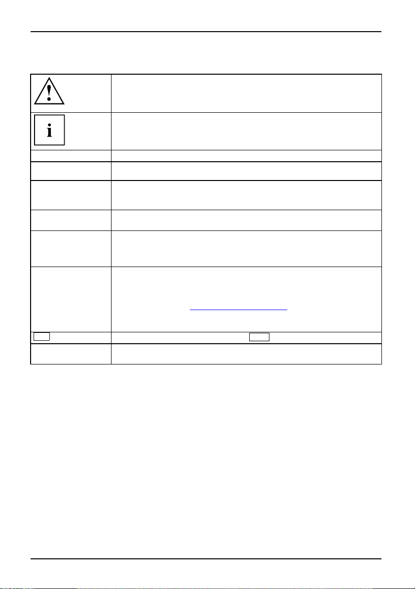
Notational conventions
Pay particular attention to text m a rked with t his symbol. Failure to observe
this warning will endanger your life, will damage the device or lead to loss
of data. The warranty will be invalidated if you cause defects in the device
through failure to take notice of this warning
indicates important informat
ion that is required to use the device properly.
►
This style
This style
This style
"This style"
Abc
This style
indicates an activity that must be performed in th e order shown
indicates a result
flags data entered using the keyboard in a program dialog or command
line, e.g. your password (Name123) or a command to launch a program
(start.exe)
refers to information displayed by a program on the screen, e.g.:
Installation is completed
is for
• terms and texts in a s oftwar
• names of programs or files, e.g. Windows or setup.exe.
is for
• cross-references to another section, e .g. "Safety information"
• Cross-references to an external source, e.g. a web address: For more
information, go to"
• indicates names of CDs and DVDs as well as names and titles of other
materials, e.g.: "CD/DVD Drivers & Utilities" or "Safety" manual
refers to a key on the keyboard, e.g.:
flags concepts and text that are emphasised or highlighted, e.g.: Do not
switch o ff device
www.fujitsu-siemens.com"
e user interface, e.g .: ClickSave.
F10
2 A26391-K233-Z120-1-7619, edition 1
Page 11

Important notes
Take note of the safety hints provided in the "Safety" manual, in the "Professional
Notebook" operating manual and in this manual.
Important notes
A26391-K233-Z120-1-7619, edition 1 3
Page 12
Ports and operating elements
Ports and operating elements
Ports
This chapter presents the individual hardw a re components of your notebook. You can obtain
an overview of the ports and operating elements of the notebook. Please familiarise yourself
with these components before you start to work with your notebook.
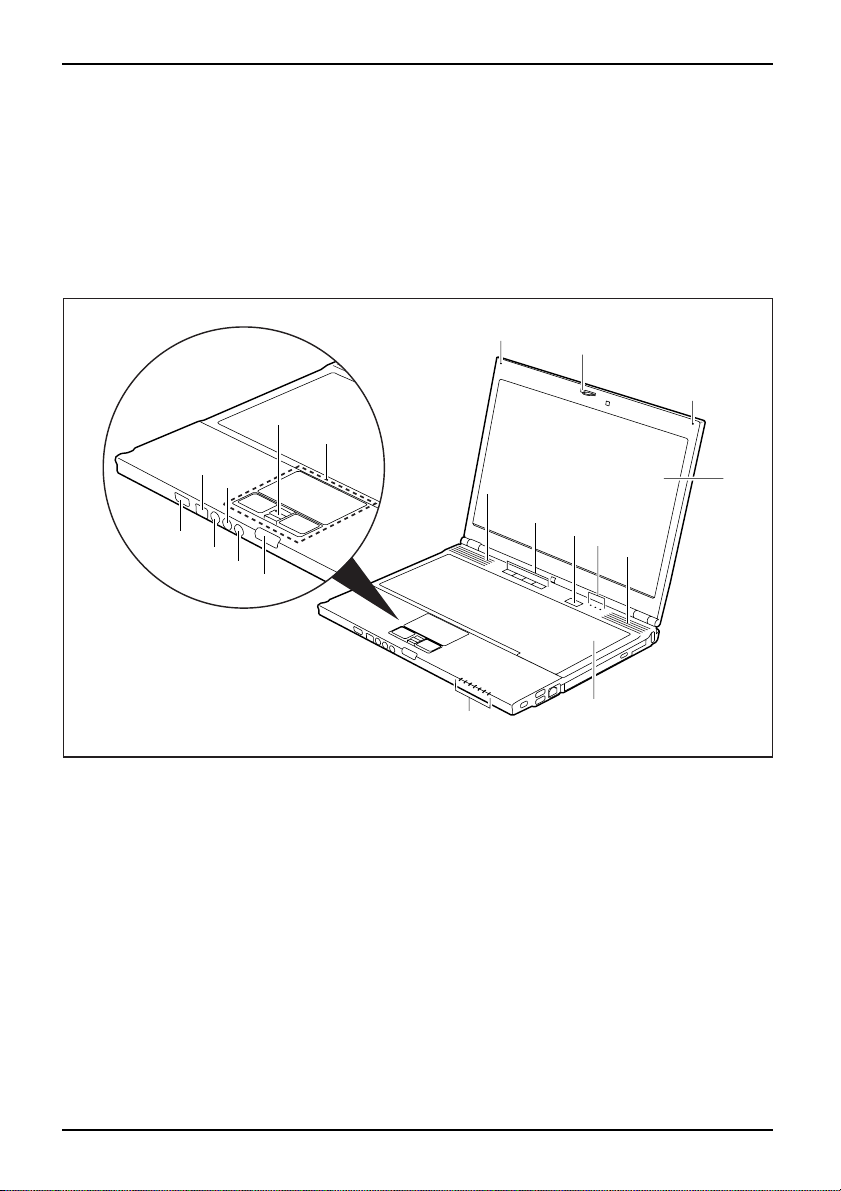
Notebook open
Camera(optional)MicrophoneLCDscreenLoudspeakerEasyLaunchkeysStatusindicatorsLoudspeakerKeyboardTouchpadandtouchpadbuttonsFingerprintsensorScreenlockLoud speakerportMicrophoneportFi reWireportON/OFFswitchforradiocomponents
15
13
16
14
1 = Camera (optional)
2 = Microphone
3 = LCD screen
4 = Loudspeaker
5 = Easy Launch keys
6 = ON/OFF switch
7 = Status indicators
8 = Keyboard
12
11
10
2
1
2
9
4
3
5
6
7
4
7
9 = Touchpad and touchpad buttons
10 = Fingerprint sensor
11 = Screen lock
12 = S-Video out socket
13 = Microphone port
14 = Loudspeaker port
15 = FireWire port
16 = ON/OFF switch for radio c omponent s
8
4 A26391-K233-Z120-1-7619, edition 1
Page 13

Left side
LANportDCinput co nnectorMonitorportPCcardslotPCcardejectbuttonInfraredinterfaceMemorycardslot
Ports and operating elemen ts
12 3 4 5
67
1 = LAN port
2 = DC input connector (DC IN)
3 = Monitor port
4 = PC card slot
Right side
ModulebayOpticaldriveInsert/ejectbutto nUSBportModem port
123 4 2
1 = Kensington Lock
2=USBports
5 = PC card eject button
6 = Infrared interface
7 = Memory card slot
3 = Modem port
4 = Module bay with optical drive
A26391-K233-Z120-1-7619, edition 1 5
Page 14

Ports and operating elements
Rear
KensingtonLock
1
1 = Kensington Lock
Underside
7
123 4
5
6
1=Bat
2 = Battery
3=Po
4 = Battery release latch
6 A26391-K233-Z120-1-7619, edition 1
tery release
rt for port replicator
5=Cov
6=Airfilter
7=Re
er for memory modules
lease mechanism for module bay
Page 15

Switching on the notebook
2
1
Ports and operating elemen ts
► Press the release button (1) and open
the LCD–display panel (2).
► Press the ON/OFF swit
the notebook on.
The power-on indicator is lit.
1
Windows XP:
You can configu re the ON/OFF switch under Start – (Settings) – Control Panel –
Performance and Maintenance – Power Options – Advanced.
Windows Vista:
You can co n figure the ON/OFF switch under Start symbol – (Settings) –
Control Panel – Mobile PC – Power Options.
If you have assigned a password, you must enter this when requested to do so, in
order to start the op erating system password. You can find more information in the
"Professional Notebook" operating instructions, "Security functions" section.
ch (1) to switch
A26391-K233-Z120-1-7619, edition 1 7
Page 16

Ports and operating elements
Switching off the N otebook
► Close all applications and shut down your operating system (please
see operating system manual).
If the notebook cannot be shut down properly, press and hold the ON/OFF butto n for
approximately four seconds. The notebook will switch off. Any unsaved data may be lost.
► Close the LCD screen.
8 A26391-K233-Z120-1-7619, edition 1
Page 17

Ports and operating elemen ts
Status indicators
Statusindicators
The status indicators provide information about the status of the power supply,
the drives and the keybo ard functions.
Power-on indicator Power indicator
Battery chargin
g indicator (first
Drive indicator
battery)
First battery indicator Num Lock indicator
Battery charging indicator
Caps Lock indicator
(second battery)
Second battery indicator Scroll Lock indicator
A26391-K233-Z120-1-7619, edition 1 9
Page 18

Ports and operating elements
The meanings of the symbols are as follows:
Power-on indicator
• Indicator continuously lit: the notebook is switched on.
• Indicator flashes: the notebook is in suspend mo de
• The indicator is not lit: the notebook is switched off or in Save-to-Disk m o de.
Power indicator
PowerindicatorIndicator
Indicator is illuminated: the mains adapter is supplying p ower to the notebook.
Drive indicator
Indicator lights up green: the hard disk drive or the CD/DVD in the optical drive of
the notebook is being accessed.
Battery charging indicator (first ba
• Indicator is illuminated (green): t
battery is fully charged, or the ma
is not installed.
• The indicator flashes yellow: the mains adapter is connected and the first
battery cannot be charged (the battery is too hot for charging).
• The indicator is illuminated (yel
first battery is being charged.
• The indicator is not illuminated: the mains adapter is not connected.
First battery indicator
• Indicator lights up green: the mains adapter is connected and the first battery
is being cha rged. The first battery is charged to between 50% and 100% of
maximum capacity.
• The indicator slowly flashes gree
is in suspend mode and power is bei
battery is charged to between 50
• The indicator lights up yellow: the ma ins adapter is connected and the first
battery is being charged. The first battery is charged to between 13% and
49% of maximum capacity.
• The indicator slowly fla shes ye
is in suspend mode and power is b
battery is charged to between 1
• The indicator lights up red: the mains ad apter is connected and the first
battery is being charged. The first battery is charged to between 0% and 12%
of maximum capacity.
• The indicator flashes red (1 se
• The indicator slowly flashes red (1 second on/5 seconds off): the notebook is in
suspend mode and power is being supplied by the first battery. The first battery
is charged to between 0% and 1 2% of maximum capacity.
• The indicator is not lit: the fi
ttery)
he mains adapter is connected and the first
ins adapter is connected and the first battery
low): the mains adapter is connected and the
n (1 second on/5 seconds off): the notebook
ng supplied by the first battery. The first
% and 100% of m aximum capacity.
llow (1 second on/5 seconds off): the notebook
eing supplied by the first battery. The first
3% and 49% of maximum capacity.
cond on/1 second off): the first battery is faulty.
rst battery is not installed.
10 A26391-K233-Z120-1-7619, edition 1
Page 19

Ports and operating elemen ts
Battery charging indicator (second battery)
• The indicator lights up yellow: the ma ins adapter is connected and the second
battery is being charg ed.
• The indicator flashes yellow: the mains adapter is connected and the second
battery cannot be charged (the battery is too hot for charging).
• The indicator is not lit: the mains adapter is connected and the second battery
is fully charged, or the mains adapter is connected and the second battery is
not installed, or the mains adapter is not connected.
Second battery indicator
• Indicator lights up green: the m
battery is being charged. The se
ains adapter is connected and the second
cond battery is charged to between 50% and
100% of maximum capa city.
• The indicator slowly flashes green (1 second on/5 seconds off): the noteb ook
is in suspend mode and power is being supplied by the second battery. The
second battery is charged to between 50% and 100% of maximum capacity.
• The indicator lights up yello
battery is being charged. The
w: the mains adapter is connected and the second
second battery is charged to between 13% and
49% of maximum capacity.
• The indicator slowly flashes yellow (1 second on/5 seconds off): the note book
is in suspend mode and power is being supplied by the second battery. The
second battery is charged to between 13% and 49% of maximum cap acity.
• The indicator lights up red: t
battery is being charged. T
he mains adapter is connected and the second
he second battery is charged to between 0% and
12% of maximum capacity.
• The indicator flash es red (1 second on/1 second o ff). The second battery is
faulty.
• The indicator slowly flashe
suspend mode and power is be
battery is charged to betwe
s red (1 second on/5 seconds off): the notebook is in
ing supplied by the second battery. The second
en 0% and 12% of maximum capacity.
• The indicator is not lit: the second battery is not installed.
Num Lock indicator
Indicator continuously lit: the
Num Lk
key has been pressed. The virtual numeric
keypad is activated. You can output the characters indicated on the upper right of
the keys.
Caps Lock indicator
Indicator continuously lit: the Caps Lock key has been pressed. All the characters
you type will appear in upper case. In the case of overlay keys, the character
printed on the upper left of the key will appear when that key is pressed.
Scroll Lock indicator
Indicator continuously lit: the key combination
Fn+Scr Lk
has been pressed.
The effect that this key has varies between applications.
A26391-K233-Z120-1-7619, edition 1 11
Page 20

Ports and operating elements
Key combinations
The following description of key combinations refers to functions when using
Microsoft Windows. Some of the following key combinations may not function in
other operating systems and with some device drivers.
Key combinations are entered as follows:
► Press and hold the first key in the combination.
► While holding the first key down, press the other key or keys in the combination.
The key combination
Ctrl
Alt Gr
+
or
external keyboards that do not not feature a
Sleep m od e
Fn+F1Sleepmode
This key combination is used to activate the suspend mode (S3).
Enable/disable loudspeakers
Fn+F3LoudspeakersLoudspeakers
This key combination switches your notebook’s loudspeakers off and on.
Switching the touchpad on/off
Fn+F4TouchpadLoudspeakers
This key combination enables and disables the touchpad.
Decrease screen brightness
Fn+F6Screenbrightne ss
This key combination decreases the brightness of the screen.
Increase screen brightness
Fn+F7Screenbrightne ss
This key combination increases the brightness of the screen.
Decrease volu me
Fn+F8Volum e
This key combination reduces the volume of the integrated loudspeakers.
Ctrl+Alt
Fn
key.
canbeusedon
12 A26391-K233-Z120-1-7619, edition 1
Page 21

Ports and operating elemen ts
Volume increase
Fn+F9Volum e
This key combination raises the volume of the inte grated loudspeakers.
Toggle output screen
Fn+F10Toggleoutput screen
If an external monitor is connected, the monitor on which the output is to be
displayed can be selected with this key combination.
You can opt to use:
• just the notebook’s LCD screen
• just the external monitor
• both the LCD screen and the external monitor
C
+
Ctrl
AltCtrl
++
Halt current operation
Ctrl+C
This key combination can be used to hal
without clearing the keyboard buff
t an operation instantly
er.
Switch between open applications
With this key combination you can switch between several open
applications.
Alt+Tab
Del
SysRq
Performwarmboot
This key combination triggers a res
press and hold both the
Ctrl
and
key. This will cause the Task Mana
combinationmustbepressedase
Ctrl+Alt+DelWarmboot
et and reboots the notebook. First
Alt
key, th en
press the
ger to be displayed. The key
cond time to reboot the system.
Back tab
This key combination moves the curs
stop.
Shift+TabBacktab
or back to the previous tabular
Key combinations using the Windows keys are detailed i n the manual
for your operating system.
Del
A26391-K233-Z120-1-7619, edition 1 13
Page 22

Ports and operating elements
Easy Launch keys
EasyLaunchkeys
Your notebook is equ ipped with four Easy Launch keys.
RE
Lock Workstation key
This key allows you to lock your workstation. However, you can also configure this key as desired.
Mobility Center key
This button starts the Mobility Center. However, you can also configure this key as desired.
E key
The E key is a simple way of activating and deactivating power management functions (e.g.
reduce screen brightness), see the "Professional Notebook" manual.
R key (recovery)
Pressing the R key opens a dialog window in which you can backu p or restore data.
Configuring Easy Launch keys
The Application Panel allows you to assign various functions to the Easy Launch keys.
Windows XP:
You will find the Application Panel under Start - (Settings) - Control Panel - Ad ditional
Control Panel Options - Application Panel.
Windows Vista:
You will find the Application Panel under Start symbol - Programs - Lifebook Application Panel.
14 A26391-K233-Z120-1-7619, edition 1
Page 23

Ports and operating elemen ts
Camera (optional)
Your device is fittedwithaVGAcamera(1),whichcanalsobeusedasawebcam.
1
Further information on the use of the camera can be found in the supplied software.
A26391-K233-Z120-1-7619, edition 1 15
Page 24

Ports and operating elements
Removing and installing the bat
NotesBattery
Only use batteries approved by Fujitsu Siemens Computers for your notebook.
Never use force when inserting or removing a battery.
Make sure that no foreign bodies get into the battery connections.
tery
Removing the battery
► Switch the notebook off and pull the power plug out of the mains socket.
Battery
► Close the LCD screen so that it locks i
► Disconnect all cables connected to the notebook.
► Turn your notebook over and place it on
an anti-slip cloth on this surface to p
nto place.
a stable, flat and clean surface. If necessary, lay
revent the notebook from being scratched.
1
2
3
► Slide the release but
► Slide the battery lock (2) in the direction of the arrow as far as possible and hold it in place.
► Remove the battery fro
16 A26391-K233-Z120-1-7619, edition 1
ton in direction of the arrow (1).
m the battery compartment (3).
Page 25

Installing battery
Ports and operating elemen ts
► Position the battery a
► Push the battery into the battery slot until y ou feel it lock into place (1).
► Slidethereleasebutto
t the edge.
n in direction of the arrow (2).
A26391-K233-Z120-1-7619, edition 1 17
Page 26

Ports and operating elements
Removing and installing the air filter
Clean the existing air filter regularly. Dirty air filters will lead to an increased
temperature inside the device. Operating temperatures which are too high
can lead to loss of data and unreliable operation.
Air filter removal
► Switch off your notebook and disconnect the power plug from the m ains.
► Close the LCD screen so that i
► Disconnect all cables connected to the notebook.
► Turn your notebook over and pla
a non-slip cloth on this surfa
t locks into place.
ce it on a stable, flat and clean surface. If necessary, lay
ce to prevent the notebook from being scratched.
1
► Press an d hold the locking tab on the air filter (1).
► Remove the air filter from its slot (2).
► Clean the air filter with a dry brush.
2
1
18 A26391-K233-Z120-1-7619, edition 1
Page 27

Install air filter
Make sure that the arrow (a) on the air filter points in the correct direction and that you
reinsert the air filter with the same orientation that it had before the cleaning operation.
Ports and operating elemen ts
a
1
► Insert the air filter at and angle into the slot (1) and ensure that you feel it click into place.
► Turn the notebook the right way up and place it on a fl at surface.
► Reconnect the cables that you disconnected previously.
A26391-K233-Z120-1-7619, edition 1 19
Page 28

Ports and operating elements
Module
ModulebayModule
The design of your notebook enables the flexible use of notebook batteries and drives. The
following modules can be operated in the module bay of your notebook:
• DVD/CD-R/RW drive
• DVD Super Multi Drive
• Second batt ery
• Blind insert (Weight Saver)
Only use modules designed for your notebook.
Do not use force when installing or removing the module.
Make sure that no foreign objects enter the module bay.
You can swap modules during operation. This means you do not
need to switch off the notebook.
To replace a module, simply click on the corresponding icon in the
task bar and then on Exit or Select - Exit.
The module can now be removed without any further actions being necessary.
Removing a module
1
2
aver
ModuleDriveWeightS
► Slide the release mechanism (1) in the direction of the arrow and hold.
► Now pull the module (2) out of the module bay.
20 A26391-K233-Z120-1-7619, edition 1
Page 29

Installing a module
1
2
a
Ports and operating elemen ts
► Place the module into t
► Push the module into the module bay until you feel it locking into place.
he module bay so that the contacts enter first.
SIM card
Follow the instructio
Inserting the SIM card
► Switch the notebook off and pull the power plug out of the mains socket.
► Close the LCD screen so that it locks into place.
► Disconnect all cables conn ected to the notebook.
► Turn your notebook over and place it on a stable, flat and clean surface. If necessary, lay
an anti-slip cloth on this surface to prevent the notebook from being scratched.
► Remove the battery (see Section "
► Reinstall the bat
► Turn the notebook the right way up and place it on a fl at surface.
► Reconnect the cabl
tery (see "
ns supplie d by the provider of the SIM card.
Removing the battery", Page 16).
► SlidetheSIMcardintotheslot(1)(withthe
contacts facing upwards) until it engages.
► Slide the clip (a) of the SIM card in the
direction of the arrow (2).
Installing battery", Page 17).
es that you disconnected previously.
A26391-K233-Z120-1-7619, edition 1 21
Page 30

Ports and operating elements
2
a
1
Removing a SIM card
► Switch the notebook off and pull the power plug out of the mains socket.
► Close the LCD screen so that it locks into place.
► Disconnect all cables connected to the notebook.
► Turn your notebook over and place it on a stable, flat and clean surface. If necessary, lay
an anti-slip cloth on this surface to prevent the notebook from being scratched.
► Remove the battery (see Section "
Removing the battery", Page 16).
► Slide the clip (a) of the SIM card in the
direction of the arrow (1).
► Press on the edge of the SIM card so that
it jumps up slightly out of the slot.
► Pull the SIM card o ut of the slot in the
direction of the arrow (2).
► Reinstall the battery (see "
► Turn the notebook the right way up and place it on a flat surface.
► Reconnect the cables that you disconnected previously.
Installing battery", Page 17).
22 A26391-K233-Z120-1-7619, edition 1
Page 31

Ports and operating elemen ts
Radio components: UMTS (optional)/wireless LAN/Bluetooth
WirelessLANBluetoothUMTS
The modules for radio components are switched off during shipping.
Switching the radio components on and off
The installation of a wireless L AN, Bluetooth or UMTS module not approved by Fujitsu
Siemens Computers GmbH voids the permits (CE!, FCC) issued for this device.
► Slide the ON/OFF switch into the "ON"
position to activate the radio components.
WirelessLANWirelessLANBl ue toothBluetooth
or
► Slide the ON/OF F switch to the
"OFF" position to deactivate the
radio components.
The Bluetooth and UMTS modules and the wireless LAN transmission unit (antenna)
will also be switched off when you switch off the radio components.
You can also deactivate the wireless components individually in the BIOS Setup.You
must have assigned the supervisor password in order for this function to be available.
Pay attention to the additional safety notes for devices with radio
components provided in the "Safety" manual.
Details on using Wireless LAN can be found the online help system
included in the Wireless LAN software.
You can find more information on how to use Bluetooth on the C D you
received with your Bluetooth software.
You can obtain more information on UMTS from your service provider.
A26391-K233-Z120-1-7619, edition 1 23
Page 32

Removing and installing components
during servicing
Removing and installing compo
nents
during servicing
Only qualified technicians should repair your notebo ok. Unauthorised
opening or incorrect repair may greatly endanger the user (electric shock,
fire risk) and will invalidate your warranty.
Servicing
Components
You may remove and install the components described in this chapter yourself
after c onsulting the Hotline/Help Desk.
If you remove and install components without consulting the Hotline/Help
Desk, then the warranty of your notebook will be voided.
Notes on installing and removing boards and components
• Switch the notebook off and pull the power plug out of the mains socket.
• Remove the battery.
• Take care when you u se the locking mechanisms on the battery and any other component.
• Never use sharp objects suc
NotesBoardESD
Boards with electrostatic sensitive device s (ESD) are marked with the label
shown.
When handling boards fitted with ESDs, you must always observe the following
points:
• You must always discharge static build up (e.g. by touching a grounded
object) before working.
• The equipment and tools you use must be free of static c harges.
• Remove the power plug from the mains supply before inserting or removing
boards containing ESDs.
• Always hold boards with ESDs b y their edges.
• Never touch pins or conductors on boards fitted with ESDs.
h a s screwdrivers, scissors or knives as leverage to remove covers.
24 A26391-K233-Z120-1-7619, edition 1
Page 33

Removing and installing components
during servicing
Removing and installing memory
MainmemoryMemoryexpansionMemoryupgradeSystemexpansion
The notebook will not start without memory modules, as no fixed RAM is installed.
Your notebook supports dual-channel DDR2 technology.
The dual-channel DDR2 technology can only be used with two identical memory
modules. When two different memory modules are installed, only "single-channel"
mode is supported. This reduces the performance of your notebook.
With a m emory configuration of 4 Gbytes, the visible and usable main memory may
be reduced to 3 Gbytes (depending o n notebook configuration).
If you are asked by the Hotline/Help Desk to remove and install the memory
modules yourself, proceed as follows:
Pay attention to the relevant safety notes provided in the " Importa nt notes" chapter.
The notebook must be switched off when installing/removing the memory
modules, it must not be in Suspend mode.
Only use approved memory expansion modules in your notebook
(see Section "
Never use force when installing or removing memory modules.
Make sure that foreign objects do not fall into the me m ory expansion compartment.
Individual components (e.g. th
during operation. Therefore,
switching off the notebook bef
Otherwise, there is a risk of su
As some non-ESD safe component
on installing and removing boa
Technical data", Page 28).
e processor heat sink) can become very hot
we recommend that you wait one hour after
ore removing or installing the memory modules.
ffering burns!
s are exposed, please observe the section "
rds and components", Page 24.
modules
Notes
► Switch your notebook off and unplug th e mains adapter from the mains outlet.
► Close the LCD screen so that it locks into place.
► Disconnect all cables conn ected to the notebook.
► Turn your notebook over and place it on a stable, flat and clean surface. If necessary, lay
an anti-slip cloth on this surface to prevent the notebook from being scratched.
► Remove the battery (see "
A26391-K233-Z120-1-7619, edition 1 25
Removing the battery", Page 16).
Page 34

Removing and installing components
Removing cover
during servicing
1
1
2
► Remove the screw
► Pull the cover off the notebook (2).
s(1).
Removing memory modules
► Carefully push the two mounting
clips outwards (1).
MemoryexpansionMemorymodule
The memory module snaps upwards (2).
3
2
1
1
26 A26391-K233-Z120-1-7619, edition 1
► Pull the memory module out of its slot
in the direction of the arrow (3).
Page 35

Removing and installing components
Installing a memory module
2
1
a
Attaching the cover
during servicing
► Insert the memory module with the contacts
and the recess (a) facing the slot (1).
MemoryexpansionMemorymodule
► Carefully push the memory module
downwards until you feel it click
into place (2).
2
2
1
► Place the cover in the correct mounting position (1).
► Secure the cover with the screws (2).
► Re-installing the battery (see "
► Turn the notebook the right way up and place it on a fl at surface.
► Reconnect the cables that you disconnected previously.
A26391-K233-Z120-1-7619, edition 1 27
Installing battery" , Page 17).
Page 36

Technical data
Technical data
Notebook
Technicaldata
General
Processor
Main memory
Suitable modules • DVD/CD-R/RW drive
Electrical d ata
Regulations complied with
Protection class II
Maximum power consumption (notebook on with
battery charging)
LCD screen
Screen size (diagonal) 13.3 inch WXGA (Wide XGA), TFT
Max. resolution
Graphics card
Chip GMA X 3100
Video memory (VRAM) Shared memory
Audio
Sound chip ALC262
Input devices
Keyboard 86 keys
Touchpad/TouchStick 2 buttons and 1 finger pressure
Slots
PC card slot (CardBus/PCMCIA) PCMCIA 1 x Type II
Memory card slot
SIM card slot
The installation and removal of memory modules in one of the two slots
should only be carried out by an authorised technician.
Intel Dual Core 2
Maximum 4 GByte
2slots-max.4GBDD2
1 GByte or 2 GByte DDR2 SDRAM SO-DIMM
module, 667 MHz
•DVDSuperMultiDrive
• Second battery
• Blind insert (Weight Saver)
CE, CE!
80 W
1280 x 80 0/16 million colours
1 x MS/xD/SD Card
1x
sensor
28 A26391-K233-Z120-1-7619, edition 1
Page 37

Technical data
Ports
Monitor port 15-pin socket
LAN port
Socket, RJ45
Microphone port 3.5 mm mono mini-jack
Headphone port 3.5 mm stereo mini jack
S-Video out socket
Modem port
Infrared interface
FireWire port
Mini jack
Connector, RJ11
IrDA 1.1
S400, 4-pin
Docking port 100-pin
USB port 3 x USB 2.0
Environmental conditions
Environment class (3K2) DIN IEC 721
Mechanical class (7M2) DIN IEC 721
Temperature
Operation 5 °C ... 35 °C
Transport
-15 °C ... 60 °C
Dimensions
Width x depth x height 314 mm x 234 mm x 31.5 mm – 33.5 mm
Weight (depending on confi gurat
ion)
Approx.1.6–2.1kg
The data sheet for this notebook contains further technical data. You can find the data
sheet on your notebook or on the supplied "
Drivers & Utilities" CD/DVD. The data
sheet can a lso be downloaded fro m the Internet at "www.fujitsu-siemens.com".
Battery
data
Technical
Rated voltage 10.8 V
Rated capacity 5200 mAh
The operating time depe nds on the device configuration, the active
applications and the energy saving settings.
A26391-K233-Z120-1-7619, edition 1 29
Page 38

Technical data
Mains adapter
Technicaldata
Primary
Rated voltage
Rated frequency 50 Hz to 60 Hz (automatic)
Secondary
Rated voltage 19 V
Max. rated current 4.22 A
An additional mains adapter or power cable can be ordered at any time.
100 V to 240 V (automatic)
30 A26391-K233-Z120-1-7619, edition 1
Page 39

Index
Index
A
Alt+Tab 13
B
Back tab 13
Battery
important notes 16
removing 16
Bluetooth 23
Switching off 23
Switching on 23
Board 24
C
Camera (optional) 4
Components
installing / removing 24
Ctrl+Alt+Del 13
Ctrl+C 13
D
DC input connector 5
Drive
Removing 20
E
Easy Launch keys 4, 14
ESD 24
F
Fingerprint sensor 4
FireWire port 4
Fn + F1 12
Fn + F10 13
Fn + F3 12
Fn + F4 12
Fn + F6 12
Fn + F7 12
Fn + F8 12
Fn + F9 13
I
Indicator
Power indicat or 10
Infrared interface 5
Insert/eject button 5
K
Kensington Lock 6
Keyboard 4
L
LAN port 5
LCD screen 4
Loudspeaker 4
Loudspeaker port 4
Loudspeakers
disable 12
enable 12
M
Main memory 25
Memory card slot 5
Memory expansion 25
installing 27
removing 26
Memory module
installing 27
removing 26
Memory upgrade 25
Microphone 4
Microphone port 4
Modem port 5
Module 20
Removing 20
Module bay 5, 20
Monitor port 5
N
Notes
battery 16
boards 24
O
ON/OFF switch for radio components 4
Optical drive 5
P
PC card eject button 5
PC card slot 5
Ports 4
Power indicator 10
A26391-K233-Z120-1-7619, edition 1 31
Page 40

Index
S
Screen brightness
decrease 12
increase 12
Screen lock 4
Servicing 24
Shift+Tab 13
Sleep mode
activating 12
Status indicators 4, 9
System expansion
memory expansion 25
T
Technical data
battery 29
Mains adapter 30
notebook 28
Toggle output screen 13
Touchpad
disable 12
Touchpad and touchpad buttons 4
U
UMTS 23
USB port 5
V
Volum e
decrease 12
increase 13
W
Warm boot 13
Weight Saver
Removing 20
Wireless LAN 23
Switching off 23
Switching on 23
32 A26391-K233-Z120-1-7619, edition 1
 Loading...