

Page 1

Fujitsu LifeBook
®
P7230 Notebook
User’s Guide
Page 2

Page 3

Copyright & Trademark Information
Copyright
Fujitsu Computer Systems Corporation has made every
effort to ensure the accuracy and completeness of this
document. However, as ongoing development efforts are
continually improving the capabilities of our products, we
cannot guarantee the accuracy of the contents of this document. We disclaim liability for errors, omissions, or future
changes.
Fujitsu, the Fujitsu logo, and LifeBook are registered trademarks of Fujitsu Limited.
Microsoft, Windows and Windows Vista are either registered trademarks or trademarks of Microsoft Corporation
in the United States and/or other countries.
PCMCIA is a trademark of the Personal Computer Memory
Card International Association.
Centrino, Intel, and Intel Core are trademarks or registered
trademarks of Intel Corporation or its subsidiaries in the
United States and other countries.
OmniPass is a trademark of Softex, Inc.
Atheros and Super AG are registered trademarks of Atheros
Communications, Inc.
Adobe, Acrobat, and Acrobat Reader are either registered
trademarks or trademarks of Adobe Systems Incorporated
in the United States and/or other countries.
Sigmatel is a registered trademark of Sigmatel, Inc.
Bluetooth is a registered trademark of Bluetooth SIG, Inc.
All other trademarks mentioned herein are the property of
their respective owners.
The DVD player found in some models of the LifeBook
notebook incorporates copyright protection technology
that is protected by method claims of certain U.S. patents
and other intellectual property rights owned by Macrovision Corporation and other rights users. Use of this copyright protection technology must be authorized by
Macrovision Corporation, and is intended for home and
other limited viewing uses only unless authorized by
Macrovision Corporation. Reverse engineering or disassembly is prohibited. All other trademarks mentioned
herein are the property of their respective owners.
© Copyright 2007 Fujitsu Computer Systems
Corporation. All rights reserved. No part of this publication
may be copied, reproduced, or translated, without prior
written consent of Fujitsu Computer Systems Corporation.
No part of this publication may be stored or transmitted in
any electronic form without the written consent of
Fujitsu Computer Systems Corporation.
B5FJ-2471-02EN-00
WARNING
Handling the cord on this product or cords
associated with accessories sold with this
product, will expose you to lead, a
chemical known to the State of California
to cause birth defects or other
reproductive harm.
Wash hands after handling.
DECLARATION OF CONFORMITY
according to FCC Part 15
Responsible Party Name: Fujitsu Computer Systems Corporation
Address: 1250 E. Arques Avenue, MS 122
Sunnyvale, CA 94085
Telephone: (408) 746-6000
Declares that product: Model Configuration: LifeBook P7230 Notebook
Complies with Part 15 of the FCC Rules.
This device complies with Part 15 of the FCC rules. Operations are subject to the following two conditions:
(1) This device may not cause harmful interference, (2) This device must accept any interference received,
including interference that may cause undesired operation.
Page 4
LifeBook P7000 Series Notebook
IMPORTANT SAFETY INSTRUCTIONS
This unit requires an AC adapter to operate. Use only UL
Listed I.T.E. Adapters with an output rating of 16 VDC,
with a minimum current of 3.75 A.
AC adapter output polarity:
+
When using your notebook, basic safety precautions
should always be followed to reduce the risk of fire, electric shock and injury to persons, including the following:
■
Do not use this product near water for example,
near a bathtub, washbowl, kitchen sink or laundry
tub, in a wet basement or near a swimming pool.
■
Avoid using the modem during an electrical storm.
There may be a remote risk of electric shock from
lightning.
■
Do not use the modem to report a gas leak in the
vicinity of the leak.
■
Use only the power cord and batteries indicated in
this manual. Do not dispose of batteries in a fire.
They may explode. Check with local codes for
possible special disposal instructions.
■
To reduce the risk of fire, use only No. 26 AWG or
larger UL Listed or CSA Certified Telecommunication Line Cord.
■
For TV Tuner Models: To protect from overvoltages
and transients on the Cable Distribution System, make
sure that the outer shield of the coaxial cable is connected to earth (grounded) at the building premises as
close to the point of cable entrance as practicable, as
required per NEC Article 820.93, ANSI/NFPA 70:
2005. If you have questions about your CATV installation, contact your service provider.
SAVE THESE INSTRUCTIONS
For Authorized Repair Technicians Only
RECYCLING YOUR BATTERY
Over time, the batteries that run your mobile computer
will begin to hold a charge for a shorter amount of time;
this is a natural occurrence for all batteries. When this
occurs, you may want to replace the battery with a fresh
one*. If you replace it, it is important that you dispose of
the old battery properly because batteries contain materials that could cause environmental damage if disposed
of improperly.
Fujitsu is very concerned with environmental protection, and has
enlisted the services of the Rechargeable Battery Recycling Corporation
(RBRC)**, a non-profit public
service organization dedicated to
protecting our environment by recy-
cling old batteries at no cost to you.
RBRC has drop-off points at tens of thousands of locations throughout the United States and Canada. To find
the location nearest you, go to www.RBRC.org
800-822-8837.
If there are no convenient RBRC locations near you, you
can also go to the EIA Consumer Education Initiative
website (http://EIAE.org/
) and search for a convenient
disposal location.
Remember – protecting the environment is a cooperative effort, and you should make every effort to protect it
for current and future generations.
* To order a new battery for your Fujitsu mobile
computer, go to the Fujitsu shopping site at
www.shopfujitsu.com
in the US or www.fujitsu.ca/
products/notebooks in Canada.
** RBRC is an independent third party to which Fujitsu
provides funding for battery recycling; RBRC is in
no way affiliated with Fujitsu.
or call 1-
■
CAUTION - HOT SURFACE: The bottom
of this notebook computer can become
hot when used for long periods of time.
When using this notebook, take caution
to limit long term or continuous use while
resting it on exposed skin, such as the lap.
■
Danger of explosion if Lithium (clock)
battery is incorrectly replaced. Replace
only with the same or equivalent type
recommended by the manufacturer. Dispose of used batteries according to the
manufacturer’s instruction.
For continued protection against risk of
fire, replace only with the same type and
rating fuse.
Page 5

Table of Contents
Fujitsu LifeBook® P7230 Notebook
Table of Contents
1
PREFACE
Preface
About This Guide . . . . . . . . . . . . . . . . . . . . . . . . .1
Fujitsu Contact Information . . . . . . . . . . . . . . . . .1
Warranty . . . . . . . . . . . . . . . . . . . . . . . . . . . . . . .1
2
GETTING TO KNOW YOUR
LIFEBOOK NOTEBOOK
Overview
Unpacking . . . . . . . . . . . . . . . . . . . . . . . . . . . . . .5
Locating the Controls/Connectors
Top and Front Components . . . . . . . . . . . . . . . . .6
Left-Side Panel Components . . . . . . . . . . . . . . . .8
Right-Side Panel Components . . . . . . . . . . . . . . .9
Rear Panel Components . . . . . . . . . . . . . . . . . . .10
Bottom Components . . . . . . . . . . . . . . . . . . . . .11
Status Indicator Panel
Hard Disk/Optical Drive Access Indicator . . . . . .13
Battery Charging Indicators . . . . . . . . . . . . . . . .13
Battery Level Indicators . . . . . . . . . . . . . . . . . . .13
Num Lock Indicator . . . . . . . . . . . . . . . . . . . . . .13
Caps Lock Indicator . . . . . . . . . . . . . . . . . . . . . .13
Scroll Lock Indicator . . . . . . . . . . . . . . . . . . . . . .13
Keyboard
Using the Keyboard . . . . . . . . . . . . . . . . . . . . . .14
Numeric Keypad. . . . . . . . . . . . . . . . . . . . . . . . .15
Windows Keys . . . . . . . . . . . . . . . . . . . . . . . . . .15
Cursor Keys . . . . . . . . . . . . . . . . . . . . . . . . . . . .15
Function Keys. . . . . . . . . . . . . . . . . . . . . . . . . . .16
Touchpad Pointing Device
Clicking . . . . . . . . . . . . . . . . . . . . . . . . . . . . . . .17
Double-Clicking . . . . . . . . . . . . . . . . . . . . . . . . .17
Dragging . . . . . . . . . . . . . . . . . . . . . . . . . . . . . .18
Scrolling . . . . . . . . . . . . . . . . . . . . . . . . . . . . . . .18
Touchpad Control Adjustment . . . . . . . . . . . . . .18
Volume Control
Controlling the Volume . . . . . . . . . . . . . . . . . . .19
LifeBook Application Panel
Configuring the Application Panel . . . . . . . . . . .21
Flexible Bay Devices
Removing and Installing Modular Devices . . . . .23
3
GETTING STARTED WITH
YOUR LIFEBOOK NOTEBOOK
Power Sources
Connecting the Power Adapters . . . . . . . . . . . . .27
Display Panel
Opening the Display Panel . . . . . . . . . . . . . . . . .28
Adjusting Display Panel Brightness . . . . . . . . . . .28
Closing the Display Panel . . . . . . . . . . . . . . . . . .28
Starting Your LifeBook Notebook
Power On. . . . . . . . . . . . . . . . . . . . . . . . . . . . . .29
Boot Sequence . . . . . . . . . . . . . . . . . . . . . . . . . .29
Hard Disk Drive Passwords . . . . . . . . . . . . . . . . .29
BIOS Setup Utility. . . . . . . . . . . . . . . . . . . . . . . .29
Booting the System . . . . . . . . . . . . . . . . . . . . . .30
Starting Windows Vista the first time . . . . . . . . . 30
Starting Windows XP the First Time . . . . . . . . . . 31
Registering Your LifeBook notebook. . . . . . . . . . 31
Installing Click Me! . . . . . . . . . . . . . . . . . . . . . .31
Page 6

LifeBook P7000 Notebook
Power Management
Suspend/Resume/Power On Button. . . . . . . . . .32
ECO Button . . . . . . . . . . . . . . . . . . . . . . . . . . . .32
Suspend Mode. . . . . . . . . . . . . . . . . . . . . . . . . . 32
Hibernation (Save-to-Disk) Feature . . . . . . . . . . 33
Windows Power Management . . . . . . . . . . . . . . 33
Restarting the System. . . . . . . . . . . . . . . . . . . . . 33
Power Off . . . . . . . . . . . . . . . . . . . . . . . . . . . . . 33
4
USER-INSTALLABLE FEATURES
Lithium ion Battery
Recharging the Batteries. . . . . . . . . . . . . . . . . . . 37
Replacing the Battery . . . . . . . . . . . . . . . . . . . . . 38
Optical Drive
Media Player Software . . . . . . . . . . . . . . . . . . . . 39
Loading a DVD or CD . . . . . . . . . . . . . . . . . . . . 39
Removing Media . . . . . . . . . . . . . . . . . . . . . . . .40
Using the Optical Drive Software . . . . . . . . . . . . 40
Using the Optical Drive on Battery Power . . . . . 40
Emergency Tray Release. . . . . . . . . . . . . . . . . . . 41
PC Cards
Inserting/Removing PC Cards . . . . . . . . . . . . . . 43
5
WIRELESS LAN USER GUIDE
Before Using the Wireless LAN
Wireless LAN Modes Using this Device . . . . . . . 54
Wireless Network Considerations. . . . . . . . . . . . 55
Deactivating the WLAN Device . . . . . . . . . . . . . 55
Activating the WLAN Device . . . . . . . . . . . . . . . 56
Configuration of the WLAN Device
Configuring the WLAN . . . . . . . . . . . . . . . . . . . 57
Troubleshooting the WLAN
Troubleshooting. . . . . . . . . . . . . . . . . . . . . . . . . 63
Wireless LAN Glossary
Glossary. . . . . . . . . . . . . . . . . . . . . . . . . . . . . . . 64
IP address information
Additional information . . . . . . . . . . . . . . . . . . . . 66
WLAN Specifications
Specifications . . . . . . . . . . . . . . . . . . . . . . . . . . . 67
Using the Bluetooth Device
What is Bluetooth? . . . . . . . . . . . . . . . . . . . . . . 68
Where to Find Information About Bluetooth . . . 68
Memory Stick/SD/xD Slot
Inserting Memory Stick/SD/xD Cards. . . . . . . . . 44
Removing A Memory Stick/SD/xD Card . . . . . . 45
Memory Upgrade Module
Accessing the Memory Compartment . . . . . . . . 46
Removing a Memory Module. . . . . . . . . . . . . . . 46
Installing a Memory Module . . . . . . . . . . . . . . .47
Checking the Memory Capacity . . . . . . . . . . . . . 47
Device Ports
Modem (RJ-11) Telephone Port . . . . . . . . . . . . . 48
Internal LAN (RJ-45) Port. . . . . . . . . . . . . . . . . . 48
IEEE 1394 Port . . . . . . . . . . . . . . . . . . . . . . . . . . 49
Universal Serial Bus Ports . . . . . . . . . . . . . . . . . . 49
Headphone/Line-Out Jack . . . . . . . . . . . . . . . . .49
Microphone Jack . . . . . . . . . . . . . . . . . . . . . . . . 49
External Video Port . . . . . . . . . . . . . . . . . . . . . . 49
6
TROUBLESHOOTING YOUR
LIFEBOOK NOTEBOOK
Troubleshooting
Identifying the Problem . . . . . . . . . . . . . . . . . . . 71
Specific Problems . . . . . . . . . . . . . . . . . . . . . . . . 71
Troubleshooting Table . . . . . . . . . . . . . . . . . . . . 72
Power On Self Test Messages . . . . . . . . . . . . . . 79
Emergency DVD Tray Release . . . . . . . . . . . . . . 80
Modem Result Codes. . . . . . . . . . . . . . . . . . . . . 80
Restoring Pre-installed Software
Restoring the Factory Image . . . . . . . . . . . . . . . 81
Using the Shock Sensor Utility . . . . . . . . . . . . . . 82
Automatically Downloading Driver Updates. . . . 83
Page 7

Table of Contents
7
CARING FOR YOUR
LIFEBOOK NOTEBOOK
Care and Maintenance
Batteries . . . . . . . . . . . . . . . . . . . . . . . . . . . . . . .88
Floppy Disks and Drives . . . . . . . . . . . . . . . . . . .88
Media Care . . . . . . . . . . . . . . . . . . . . . . . . . . . .89
PC Cards . . . . . . . . . . . . . . . . . . . . . . . . . . . . . .89
8
SYSTEM SPECIFICATIONS
Specifications
Configuration Label . . . . . . . . . . . . . . . . . . . . . .93
Microprocessor. . . . . . . . . . . . . . . . . . . . . . . . . .93
Memory . . . . . . . . . . . . . . . . . . . . . . . . . . . . . . .93
Video . . . . . . . . . . . . . . . . . . . . . . . . . . . . . . . . .93
Audio . . . . . . . . . . . . . . . . . . . . . . . . . . . . . . . . .93
Mass Storage Device Options. . . . . . . . . . . . . . .93
Features . . . . . . . . . . . . . . . . . . . . . . . . . . . . . . .93
Device Ports . . . . . . . . . . . . . . . . . . . . . . . . . . . .94
Keyboard . . . . . . . . . . . . . . . . . . . . . . . . . . . . . .94
Power. . . . . . . . . . . . . . . . . . . . . . . . . . . . . . . . .94
Dimensions and Weight . . . . . . . . . . . . . . . . . . .94
Environmental Requirements . . . . . . . . . . . . . . .94
Popular Accessories . . . . . . . . . . . . . . . . . . . . . .94
Pre-Installed Software . . . . . . . . . . . . . . . . . . . .94
Learning About Your Software . . . . . . . . . . . . . .95
Regulatory Information . . . . . . . . . . . . . . . . . . .97
9
GLOSSARY
Glossary . . . . . . . . . . . . . . . . . . . . . . . . . . . . . .101
APPENDIX A: USING THE
FINGERPRINT SENSOR DEVICE
Fingerprint Sensor Device
Introducing the Fingerprint Sensor Device . . . .107
Getting Started. . . . . . . . . . . . . . . . . . . . . . . . .107
Installing OmniPass . . . . . . . . . . . . . . . . . . . . .107
User Enrollment . . . . . . . . . . . . . . . . . . . . . . . .108
Using OmniPass . . . . . . . . . . . . . . . . . . . . . . . .109
Configuring OmniPass . . . . . . . . . . . . . . . . . . .112
OmniPass Control Center. . . . . . . . . . . . . . . . .112
Troubleshooting . . . . . . . . . . . . . . . . . . . . . . . .113
INDEX
Index . . . . . . . . . . . . . . . . . . . . . . . . . . . . . . . .115
Page 8

LifeBook P7000 Notebook
Page 9

1
Preface
Page 10

LifeBook P7000 Notebook
Page 11
Preface
Preface
ABOUT THIS GUIDE
The LifeBook P7230 Series notebook from Fujitsu
Computer Systems Corporation is a small but powerful
computer. It is powered by an Intel® Core Solo
processor, has a built-in wide-aspect Crystal View color
display, and has a variety of other useful options to make
it a truly ultra-portable notebook.
This manual explains how to operate your LifeBook
notebook’s hardware and built-in system software.
It comes with Microsoft Windows® XP Professional,
Windows Vista™ Home Basic, or Windows Vista
Business operating system pre-installed.
Conventions Used in the Guide
Depending upon your notebook’s operating system,
different steps are required for certain procedures. Those
steps are differentiated in this manual, where applicable.
Keyboard keys and on-screen buttons appear in
brackets. Example: [Fn], [F1], [ESC], and [CTRL].
Pages with additional information about a specific topic
are cross-referenced within the text.
Example: (See page xx.)
The information icon highlights
information that will enhance your
understanding of the subject material.
The caution icon highlights information
that is important to the safe operation of
your computer, or to the integrity of your
files. Please read all caution information
carefully.
The warning icon highlights information
that can be hazardous to either you, your
LifeBook notebook, or your files. Please
read all warning information carefully.
FUJITSU CONTACT INFORMATION
Service and Support
You can contact Fujitsu Service and Support in the
following ways:
■
Toll free: 1-800-8Fujitsu (1-800-838-5487)
■
E-mail: 8fujitsu@us.fujitsu.com
■
Website:
http://www.computers.us.fujitsu.com/support
Before you place the call, you should have the following
information ready so that the customer support
representative can provide you with the fastest possible
solution:
■
Product name
■
Product configuration number
■
Product serial number
■
Purchase date
■
Conditions under which the problem occurred
■
Any error messages that have occurred
■
Type of device connected, if any
Fujitsu Online
You can go directly to the online Fujitsu Product catalog
for your LifeBook notebook going to the website at:
www.shopfujitsu.com.
You can reach Fujitsu Service and Support by going to
the Fujitsu website at www.computers.us.fujitsu.com
and clicking on the Support link.
You must have an active internet connection to use the online URL links.
WARRANTY
Your LifeBook notebook is backed by an International
Limited Warranty. Check the service kit that came with
your notebook for warranty terms and conditions.
1
Page 12

LifeBook P7000 Notebook – Section One
2
Page 13

2
Getting to Know Your LifeBook Notebook
3
Page 14

LifeBook P7000 Notebook – Section Two
4
Page 15
Getting to Know Your LifeBook
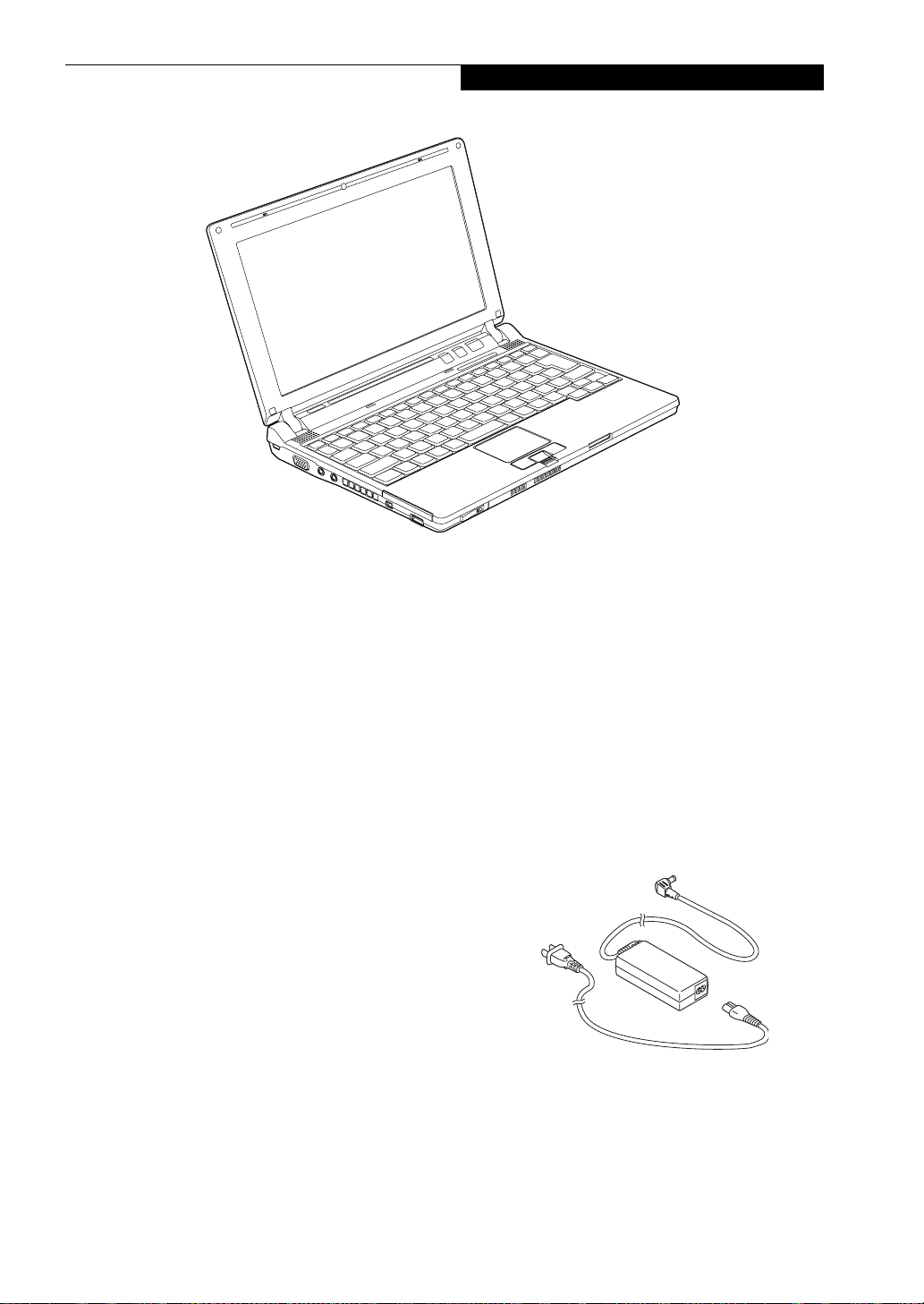
Figure 2-1 Fujitsu LifeBook P7230 notebook
Overview
This section describes the components of your Fujitsu
LifeBook P7230 notebook. We strongly recommend that
you read it before using your notebook – even if you are
already familiar with notebook computers.
UNPACKING
When you receive your LifeBook notebook, unpack it
carefully, and compare the parts you have received with
the items listed below.
■
LifeBook P7230 notebook(Figure 2-1)
■
AC adapter with AC power cord (Figure 2-2)
■
Lithium ion battery
■
Wei g ht S ave r
■
Driver and Application Restore Disc
■
Recovery Disc
■
Phone/modem (RJ-11) telephone cable
■
Getting Started Guide
■
International Limited Warranty Brochure
■
Certification of Authenticity
Depending upon the configuration of your system, one
or more of the following items may also be included:
■
Modular DVD/CD-RW Combo Drive
■
Modular Dual-Layer Multi-Format DVD Writer
■
External Floppy Disk Drive
■
Modular 2nd battery
■
Additional main high capacity battery
■
Roxio EasyMedia Creator disc
■
CyberLink application disc
■
Built-in camera disc
Once you have checked and confirmed that your LifeBook system is complete, read through the following
pages to learn about all of your notebook’s components.
Figure 2-2 AC Adapter
5
Page 16
LifeBook P7000 Notebook – Section Two
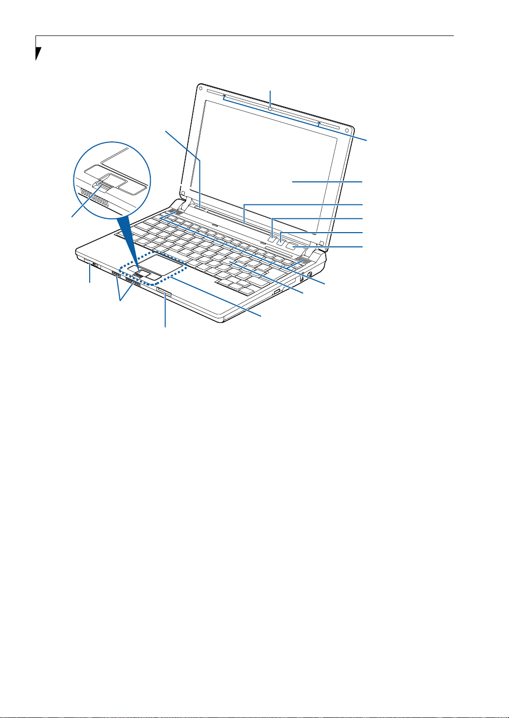
Wireless LAN On/Off Switch
Fingerprint Sensor/
Scroll Button
Built-in Camera (optional)
Built-in Microphones
Display Panel
Status Indicator Panel
Application A Button
ECO Button
Suspend/Resume/
Power On Button
PC Card Eject Button
Air Vents
Memory Stick/SD/xD Slot
Figure 2-3 LifeBook notebook with display open
Locating the Controls and Connectors
TOP AND FRONT COMPONENTS
The following is a brief description of your LifeBook
notebook’s top and front components.
Wireless LAN On/Off Switch
Allows you to turn the optional Wireless LAN device on
and off. Note that this switch is present on all models of
the LifeBook P7230 notebook, but it is functional only
on those with an optional Wireless LAN installed.
Optional Built-in Camera
The optional built-in camera has a resolution of 300K
pixels (0.3 megapixels). For instructions on using the
camera, see the help files that are included with the
camera software application.
Built-in Microphones
The two built-in microphones allow you to input mono
audio. The built-in microphones support noise-cancellation when used with applicable third-party software.
Display Panel
The display panel is a color LCD panel with back
lighting for the display of text and graphics.
6
Stereo Speakers
Keyboard
Touchpad Pointing Device
Status Indicator Panel
The Status Indicator Panel displays symbols that correspond with a specific component of your LifeBook notebook. (See Status Indicator Panel on page 13 for more
information)
Application A Button
The application button can be programmed to launch
any program the user chooses simply by pressing the
button. The default for this button is Internet Explorer.
(See Configuring the Application Panel on page 21 for
more information).
ECO Button
The ECO button launches the Power Saving Utility
which is programmed in the LifeBook Application
Pane l. (See ECO Button on page 32 for more information)
This button can also be programmed as a second application button.(See Configuring the Application Panel on
page 21 for more information).
Suspend/Resume/Power On Button
The Suspend/Resume/Power On button allows you to
suspend notebook activity without powering off, resume
your LifeBook notebook from suspend mode, and
power on your notebook when it has been shut down
from Windows. (See Suspend/Resume/Power On Button
on page 32 for more information)
Stereo Speakers
The built-in dual speakers allow for stereo sound.
Page 17

Keyboard
A full-size keyboard with dedicated Windows keys. (See
Keyboard on page 14 for more information)
Touchpad Pointing Device
The Touchpad pointing device is a mouse-like cursor
control with three buttons (left, right, and fingerprint
sensor/scroll button). (See Touchpad Pointing Device on
page 17 for more information).
Memory Stick/SD/xD Card Slot
The Memory Stick/Secure Digital (SD)/xD Picture card
slot allows you to insert a flash memory card for data
storage. This architecture allows you to transfer data
between a variety of different digital devices. (See
Inserting Memory Stick/SD/xD Cards on page 44 for more
information)
Air Vents
The air vents allow for proper cooling of the system
while it is operating.
To protect your notebook from damage
and to optimize system performance, be
sure to keep all air all vents unobstructed,
clean, and clear of debris. This may require
periodic cleaning, depending upon the
environment in which the system is used.
Getting to Know Your LifeBook
Do not operate the notebook in areas
where the air vents can be obstructed, such
as in tight enclosures or on soft surfaces
like a bed or cushion.
PC Card Eject Button
The PC Card Eject button allows you to remove a card
from the PC Card slot. (See Removing PC Cards on
page 43 for more information)
Fingerprint Recognition Sensor
The fingerprint recognition sensor allows you to
increase the security of your system by having it "recognize" your unique fingerprint. (See Fingerprint Sensor
Device on page 107 for more information)
The fingerprint recognition sensor can also be used as a
scrolling button that lets you navigate quickly through a
document without having to use the window scroll bars.
(See Scrolling on page 20 for more information)
7
Page 18
LifeBook P7000 Notebook – Section Two
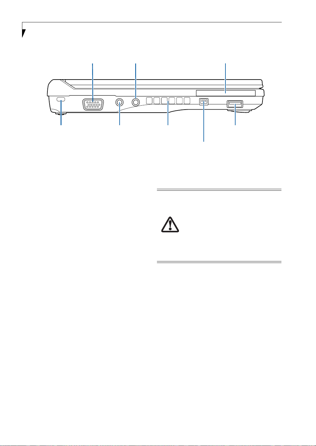
External Monitor Port
Anti-theft Lock Slot
Microphone Jack
Headphone Jack
Figure 2-4 LifeBook notebook left-side panel
LEFT-SIDE PANEL COMPONENTS
The following is a brief description of your LifeBook
notebook’s left-side components.
External Monitor Port
The external monitor port allows you to connect your
LifeBook notebook to an external monitor. (See External
Video Port on page 49 for more information)
Headphone/Line-Out Jack
The headphone/line-out jack allows you to connect
headphones or powered external speakers. (See Head-
phone/Line-Out Jack on page 49 for more information)
PC Card Slot
The PC Card Slot allows you to insert one Type II PC
Card. (See PC Cards on page 43 for more information)
USB 2.0 Ports
The USB ports allow you to connect Universal Serial Bus
2.0 devices. There are two USB port: one on the left side
of the system and one on the right. (See Universal Serial
Bus Ports on page 49 for more information)
IEEE 1394 Port
The IEEE 1394 port (also known as “Firewire”) is used
to connect between your LifeBook and a peripheral such
as a digital video camera. (See IEEE 1394 Port on page 49
for more information)
PC Card Slot
Air Vents
IEEE 1394 Port
USB 2.0 Port
Air Vents
The air vents allow for proper cooling of the system
while it is operating.
To protect your notebook from damage
and to optimize system performance, be
sure to keep all air all vents unobstructed,
clean, and clear of debris. This may require
periodic cleaning, depending upon the
environment in which the system is used.
Do not operate the notebook in areas
where the air vents can be obstructed, such
as in tight enclosures or on soft surfaces
like a bed or cushion.
Microphone Jack
The microphone jack allows you to connect an external
mono microphone. (See Microphone Jack on page 49 for
more information)
Anti-theft Lock Slot
The anti-theft lock slot allows you to attach an optional
physical lock-down device.
8
Page 19

Getting to Know Your LifeBook
Flexible Bay
Figure 2-5 LifeBook notebook right-side panel
RIGHT-SIDE PANEL COMPONENTS
The following is a brief description of your LifeBook
notebook’s right-side components.
Flexible Bay
The Flexible Bay can accommodate either the standard
DVD/CD-RW Drive or an optional modular bay battery.
If neither device is installed, the weight saver should be
installed. (See Flexible Bay Devices on page 23 for more
information)
USB 2.0 Port
The USB ports allow you to connect Universal Serial Bus
2.0 devices. There are two USB ports on the left side of
the system and one on the right. (See Universal Serial Bus
Ports on page 49 for more information)
DC Power Jack
The DC power jack allows you to plug in the AC adapter
or the optional Auto/Airline adapter to power your notebook and charge the internal Lithium ion battery.
USB 2.0 Port
DC Power Jack
9
Page 20
LifeBook P7000 Notebook – Section Two
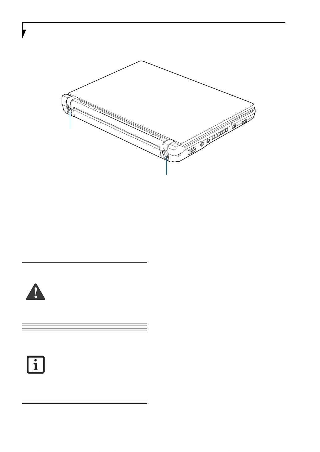
Modem Port
Figure 2-6 LifeBook notebook rear panel
LAN Port
REAR PANEL COMPONENTS
The following is a brief description of your LifeBook
notebook’s rear components.
Modem (RJ-11) Telephone Port
The Modem (RJ-11) telephone port is for attaching
a telephone line to the internal multinational 56K
modem. (See Modem (RJ-11) Telephone Port on page 48
for more information)
The internal modem is not intended for
use with Digital PBX systems. Do not
connect the internal modem to a Digital
PBX as it may cause serious damage to the
internal modem or your entire notebook.
Consult your PBX manufacturer’s
documentation for details. Some hotels
have Digital PBX systems. Be sure to find
out BEFORE you connect your modem.
The internal multinational modem is
designed to the ITU-T V.90 standard. Its
maximum speed of 53000bps is the
highest allowed by FCC, and its actual
connection rate depends on the line
conditions. The maximum speed is
33600bps at upload.
LAN (RJ-45) Port
The internal LAN (RJ-45) port is used for an internal
Fast Ethernet (10/100 Base-TX) connection.
(See Internal LAN (RJ-45) Port on page 48 for more information)
For additional information about the
multinational modem, refer to the Fujitsu
website at: us.fujitsu.com/computers.
10
Page 21
Getting to Know Your LifeBook
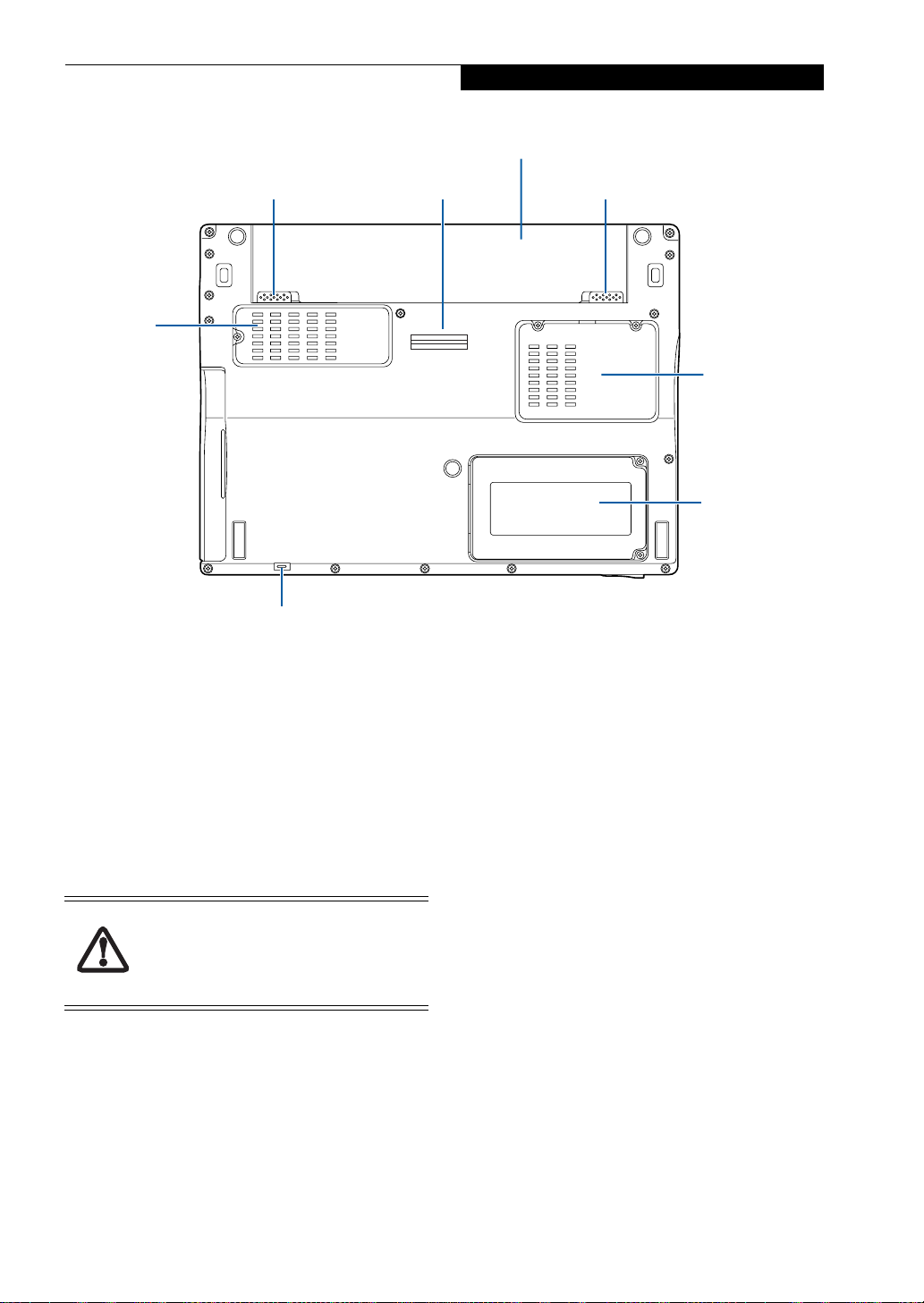
Lithium ion Battery
Battery Release Latch
Air Vents
(several
locations)
Flexible Bay Release Latch
Port Replicator Connector
Figure 2-7 LifeBook notebook bottom panel
BOTTOM COMPONENTS
The following is a brief description of your LifeBook
notebook’s bottom panel components.
Battery Release Latches
Slide the battery releases to unlatch the battery.
Port Replicator Connector
The port replicator connector docks with the connector
on the optional port replicator to provide additional
connectivity.
Before docking or undocking your
notebook with the port replicator, be sure
to touch a grounded metal object to
prevent electrostatic discharge from
affecting the computer components.
Battery Release Latch
Memory
Module
Cover
Hard Disk
Drive Cover
Memory Module Cover
Removable cover over the memory modules. (See
Removing a Memory Module on page 46 for more information)
Hard Disk Drive Cover
Removable cover over the hard disk drive. Under ordinary circumstances, it should not be necessary to
remove this cover.
Flexible Bay Release Latch
The Flexible Bay Release Latch releases the flexible bay
device for removal. (See Removing and Installing
Modular Devices on page 23 for more information)
Lithium ion Battery
The internal Lithium ion battery can be installed in the
battery bay by aligning it with the slides and pushing it
into place. The battery can be removed when swapping
with a charged battery, or when the computer is to be
stored for a long period of time. (See Lithium ion Battery
on page 37 for more information)
11
Page 22

LifeBook P7000 Notebook – Section Two
Air Vents
The air vents allow for proper cooling of the system
while it is operating.
To protect your notebook from damage
and to optimize system performance, be
sure to keep all air all vents unobstructed,
clean, and clear of debris. This may require
periodic cleaning, depending upon the
environment in which the system is used.
Do not operate the notebook in areas
where the air vents can be obstructed, such
as in tight enclosures or on soft surfaces
like a bed or cushion.
12
Page 23
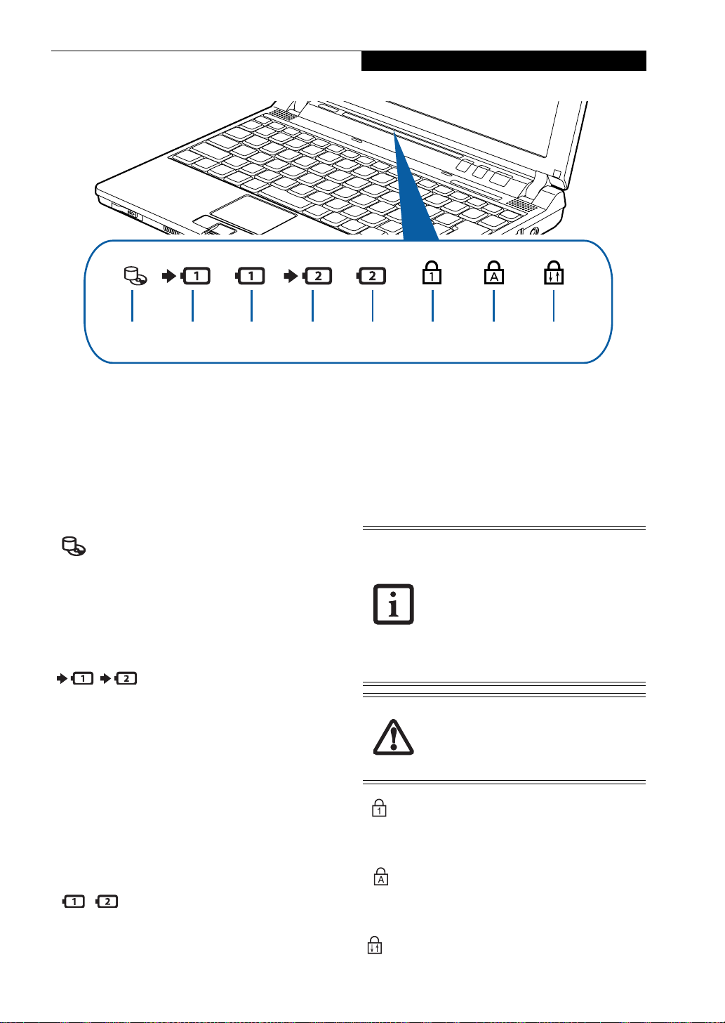
Getting to Know Your LifeBook
Optical Drive
Access
Battery 1
Charging
Indicator
Battery 1 Hard Drive/
Battery 2
Charging
Indicator
Figure 2-8 Status Indicator Panel
Status Indicator Panel
The Status Indicator displays LEDs adjacent to symbols
that correspond with specific components of your LifeBook notebook. These lights tell you how each of those
components is operating. (Figure 2-8). When you turn
off the system, all indicators will go off, except when the
battery is being charged.
HARD DISK/OPTICAL
DRIVE ACCESS INDICATOR
The Hard Disk/optical drive access indicator lights when
the hard disk or optical drive is being accessed. To
prevent corruption of data, do not press the power
button when the hard disk/optical drive access indicator
is lit.
BATTERY
CHARGING INDICATORS
When the AC adapter is connected to your system, these
indicators show the status of the specified battery
charging (either the primary battery 1 or modular
battery 2), as follows:
■
Green, solid: The battery is either fully charged or the
AC adapter is connected and there is no battery pack
installed.
■
Orange, solid: The battery pack is charging.
■
Orange, blinking: Charging is suspended due to excessively high or low battery temperature.
■
Off: No AC adapter is connected.
BATTERY LEVEL INDICATORS
The Battery Level indicators display the charge level of
the indicated battery pack, as follows:
■
Green, solid: Battery is between 50% and 100%
charged.
Battery 2 Num Lock
■
Orange, solid: Battery is between 13% and 49%
Indicator
Caps Lock Indicator
Scroll Lock
IndicatorLevel Indicator Level Indicator
charged.
■
Red, solid: Battery is between 0% and 12% charged.
■
Orange, blinking: Blinks during battery status
measurement (Four seconds after the battery is
installed).
■
Red, blinking: There is a problem with the battery.
■
Off: There is no battery installed.
■
If the battery pack is installed while the
power is turned off, the battery level
indicator will display the charge level for
five seconds after it blinks orange.
■
If the AC adapter is not connected or the
battery pack is not fully charged when
the computer is switched to standby
mode, the indicator will blink. The LED
blinks at the rate of one second on/five
seconds off.
■
Batteries subjected to shocks, vibration
or extreme temperatures can be permanently damaged.
■
A shorted battery is damaged and must
be replaced.
NUM LOCK INDICATOR
The Num Lock indicator states that the integral
keyboard is set in ten-key numeric keypad mode.
CAPS LOCK INDICATOR
The Caps Lock indicator states that your keyboard is set
to type in all capital letters.
SCROLL LOCK INDICATOR
This indicator shows that your scroll lock is active.
13
Page 24
LifeBook P7000 Notebook – Section Two
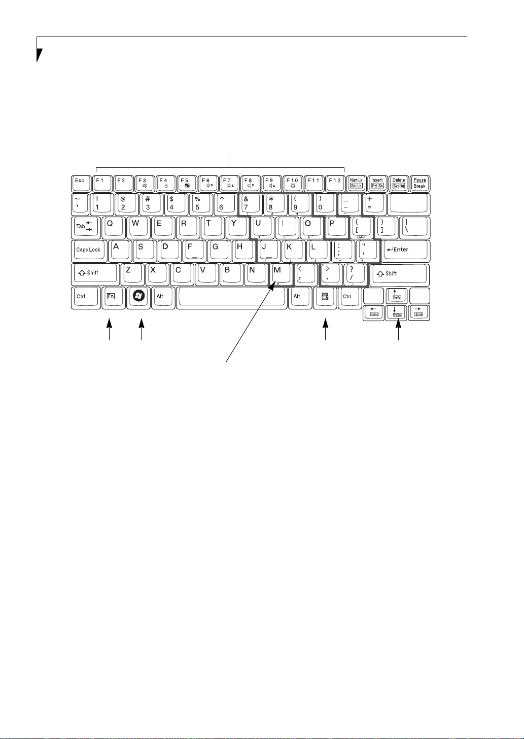
Function Keys
Back
Space
Fn Key
Windows
Start Key
Numeric Keypad
Figure 2-9 Keyboard
Keyboard
USING THE KEYBOARD
Your Fujitsu LifeBook notebook has an integral 82-key
keyboard. The keys perform all the standard functions of
a 101-key keyboard, including the Windows keys and
other special function keys. This section describes the
following keys. (Figure 2-9)
■
Numeric keypad: Your notebook allows certain keys to
serve dual purposes, both as standard characters and
as numeric and mathematical keys. The ability to toggle between the standard character and numerical keys
is controlled through the [NumLk] key.
■
Cursor keys: Your keyboard contains four arrow
keys for moving the cursor or insertion point to the
right, left, up, or down within windows, applications
and documents.
■
Function keys: The keys labeled [F1] through [F12],
are used in conjunction with the [Fn] key to produce
special actions that vary depending on what program
is running.
■
Windows keys: These keys work with your Windows
operating system and function the same as the
Windows
Application Key
Cursor Keys
onscreen Start menu button, or the right button
on your pointing device.
14
Page 25

NUMERIC KEYPAD
Certain keys on the keyboard perform dual functions as
both standard character keys and numeric keypad keys.
NumLk can be activated by pressing the [NumLk] keys.
Turning off the NumLk feature is done the same way.
Once this feature is activated you can enter numerals 0
through 9, perform addition ( + ), subtraction ( - ),
multiplication ( * ), or division ( / ), and enter decimal
points ( . ) using the keys designated as ten-key function
keys. The keys in the numeric keypad are marked on the
front edge of the key to indicate their secondary functions.
WINDOWS KEYS
Your LifeBook notebook has two Windows keys,
consisting of a Start key and an Application key. The
Start key displays the Start menu. This button functions
the same as your onscreen Start menu button. The
Application key functions the same as your right mouse
button and displays shortcut menus for the selected
item. (Please refer to your Windows documentation for
additional information regarding the Windows keys.)
CURSOR KEYS
The cursor keys are the four arrow keys on the keyboard
which allow you to move the cursor up, down, left and
right in applications. In programs such as Windows
Explorer, it moves the “focus” (selects the next item up,
down, left, or right).
Getting to Know Your LifeBook
15
Page 26

LifeBook P7000 Notebook – Section Two
FUNCTION KEYS
Your LifeBook notebook has 12 function keys, F1
through F12. The functions assigned to these keys differ
for each application. You should refer to your software
documentation to find out how these keys are used.
The [Fn] key provides extended functions for the
notebook and is always used in conjunction with
another key.
■
[Fn+F3]: Pressing [F3] while holding [Fn] will toggle
the Audio Mute on and off.
■
[Fn+F4]: Pressing [F4] while holding [Fn] will toggle
the Quick Point feature on and off. Note that the
[Fn+F4] combination only works if Manual Setting is
selected in the BIOS. (See “Entering the BIOS Setup
Utility” on page 30)
■
[Fn+F5]: Pressing [F5] while holding [Fn] allows
you to toggle between video compensation and no
compensation. (Video compensation controls spacing
on the display. When it is enabled, displays with
1024 x 768 or 800 x 600 pixel resolution will still cover
the entire screen.) Note that this function is only
applicable if Compensation is disabled in the BIOS.
(See BIOS Setup Utility on page 29 for more information).
■
[Fn+F6]: Pressing [F6] repeatedly while holding [Fn]
will lower the brightness of your display.
■
[Fn+F7]: Pressing [F7] repeatedly while holding [Fn]
will increase the brightness of the display.
■
[Fn+F8]: Pressing [F8] repeatedly while holding [Fn]
will decrease the volume of your LifeBook notebook.
■
[Fn+F9]: Pressing [F9] repeatedly while holding [Fn]
will increase the volume of your LifeBook notebook.
■
[Fn+F10]: Pressing [F10] while holding [Fn] allows
you to change your selection of where to send your
display video. Each time you press the combination
of keys you will step to the next choice. The choices,
in order, are: built-in display panel only, external
monitor only, and both built-in display panel and
external monitor.
16
Page 27
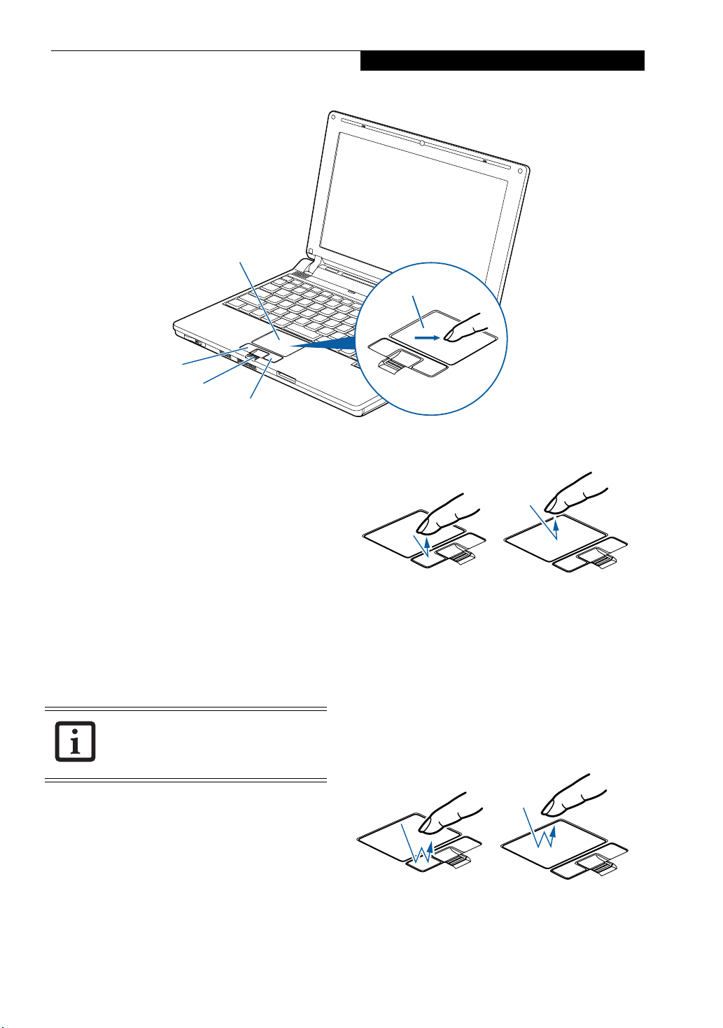
Left Button
Fingerprint Sensor/
Scroll Button
Getting to Know Your LifeBook
Touchpad
Cursor Control
Right Button
Figure 2-10 Touchpad pointing device
Touchpad Pointing Device
The Touchpad pointing device comes built into your
LifeBook notebook. It is used to control the movement
of the pointer to select items on your display panel. The
Touchpad is composed of a cursor control, a left and
right button, and a scrolling button. The cursor control
works the same way a mouse does, and moves the cursor
around the display. It only requires light pressure with
the tip of your finger. The left and right buttons function
the same as mouse buttons. The actual functionality of
the buttons may vary depending on the application that
is being used. The scrolling button allows you to navigate quickly through pages, without having to use the
scroll bars. (Figure 2-14)
The scrolling button also acts as a fingerprint sensor. For information on using the
optional fingerprint sensor, refer to “Fingerprint Sensor Device” on page 107.
CLICKING
Clicking means pushing and releasing a button. To leftclick, move the cursor to the item you wish to select,
press the left button once, and then immediately release
it. To right-click, move the mouse cursor to the item you
wish to select, press the right button once, and then
immediately release it. You also have the option to
perform the clicking operation by tapping lightly on the
Touchpad once. (Figure 2-11)
Figure 2-11 Clicking methods
DOUBLE-CLICKING
Double-clicking means pushing and releasing the left
button twice in rapid succession. This procedure does
not function with the right button. To double-click,
move the cursor to the item you wish to select, press
the left button twice, and then immediately release it.
You also have the option to perform the double-click
operation by tapping lightly on the Touchpad twice.
(Figure 2-12)
Figure 2-12 Double-clicking methods
17
Page 28
LifeBook P7000 Notebook – Section Two
■
If the interval between clicks is too
long, the double-click will not be
executed.
■
Parameters for the Touchpad can be
adjusted from the Mouse Properties
dialog box located in the Windows
Control Panel.
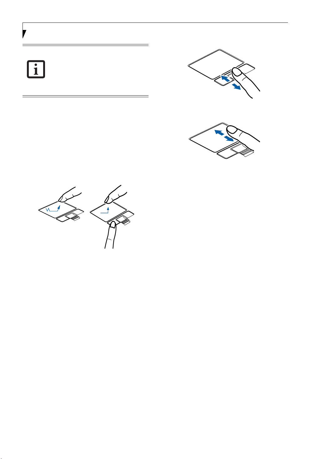
DRAGGING
Dragging means pressing and holding the left button,
while moving the cursor. To drag, move the cursor to the
item you wish to move. Press and hold the left button
while moving the item to its new location and then
release it. Dragging can also be done using the
Touchpad. First, tap the Touchpad twice over the item
you wish to move making sure to leave your finger on
the pad after the final tap. Next, move the object to its
new location by moving your finger across the
Touchpad, and then release your finger. (Figure 2-13)
Figure 2-13 Dragging methods
SCROLLING
Using the Scrolling button allows you to navigate
through a document quickly without using the window’s
scroll bars. This is particularly useful when you are
navigating through on-line pages. To use the Scrolling
button, move your finger forward or backward across
the button to scroll up or down a page. When you have
reached the desired section of the page, raise your finger.
(Figure 2-14)
Figure 2-14 Scrolling with scrolling button
Figure 2-15 Scrolling with Touchpad
TOUCHPAD CONTROL ADJUSTMENT
If you need to change or adjust any of the touchpad
control functions, you can customize them from the
Mouse properties dialog box in the Control Panel. Click
on Start, select Settings > Control Panel, then doubleclick Mouse.
Note that you can also scroll by sliding your finger up
and down the right side of the touchpad. This feature is
disabled by default, but you can enable it by going to
Start -> Control Panel -> Mouse.
The scrolling button is also used as a fingerprint sensor.
To use the fingerprint sensor device, refer to the
appendix of this document. (See Fingerprint Sensor
Device on page 107 for more information)
18
Page 29

Volume Control
Your Fujitsu LifeBook notebook has multiple volume
controls which interact with each other
Any software that contains audio files will
also contain a volume control of its own. If
you install an external audio device that
has an independent volume control, the
hardware volume control and the software
volume control will interact with each
other. It should be noted that if you set
your software volume to Off, you will
override external volume control settings.
CONTROLLING THE VOLUME
The volume can be controlled in several different ways:
■
Volume can be set from within the Volume Control on
the Taskbar.
■
Volume can be controlled with the [F8] and [F9]
functions keys. Pressing [F8] repeatedly while holding
[Fn] will decrease the volume of your notebook. Pressing [F9] repeatedly while holding [Fn] will increase
the volume of your notebook
■
Volume can be controlled by many volume controls
that are set within individual applications.
■
Certain external audio devices you might connect to
your system may have hardware volume controls.
.
.
Getting to Know Your LifeBook
Each source discussed above puts an upper limit on the
volume level that must then be followed by the other
sources.
We recommend that you experiment with the various
volume controls to discover the optimal sound level.
19
Page 30

LifeBook P7000 Notebook – Section Two
20
Page 31

Getting to Know Your LifeBook
Application A Button
ECO Button
Figure 2-16. LifeBook Application Panel
Power/Suspend/Resume Button
(for reference only)
LifeBook Application Panel
A unique feature of your notebook is the LifeBook
Application Panel. The Application Panel makes your
LifeBook notebook more than just another computer.
This panel allows you to launch selected applications
with the touch of a button.
Your LifeBook notebook is pre-installed with software
utilities that let you operate and configure your LifeBook
Application Panel. These utilities are found under
[Start] -> All Programs -> Application Panel.
The panel consists of two buttons, labeled “A” and
“ECO”. Pressing either of the application buttons will
launch a user-defined application. The defaults are as
follows:
Button Label Default Application
A Internet Explorer
ECO www.google.com
The ECO button is initially set to default to
power saving mode when it is pressed. For
more information about the power saving
mode, see “ECO Button” on page 32.
CONFIGURING THE APPLICATION PANEL
When you start your system, the LifeBook Application
Panel is automatically activated. As an application
launcher, the LifeBook Application Panel gives you a
variety of options. To set up the panel to best suit your
needs, the Application Panel Setup utility will quickly
and easily help you make the most of this valuable
feature.
By default, pressing the “A” button will open the Internet
Explorer browser. Pressing the “ECO” button will open a
power-saving utility window by default.
Either of these button defaults can be changed using the
following procedure.
To configure your LifeBook Application Panel with
the Application Panel Setup utility:
1. Click on [Start] -> All Programs.
2. Select LifeBook Application Panel from the drop-
down menu, then click on Setup of LifeBook Appli-
cation Panel. The Button Setting window will open.
The Button Setting window has tabs that correspond to
the buttons on the application panel. When you receive
your notebook, these buttons are pre-configured to
launch specific programs, as noted above.
In order to reconfigure a button to launch a different
program, follow these steps:
1. On the Button Setting window, click the tab of the
button you want to configure.
2. Ensure that the “Enable this button” check box is
selected, then click the [Application registration...]
button.
3. You can either select an application from the Start
menu, or select an application directly by clicking
the “Select from Start Menu” or “Select directly”
button, respectively.
4. Once you’ve selected an application, click [Next].
5. In the next window, you can select to play a sound
when the application starts.
21
Page 32

LifeBook P7000 Notebook - Section Two
6. Click [Finish] to complete the procedure. After this
point, whenever you click the appropriate application button, the application to which you assigned it
will start.
At the bottom of each application setup page are two
selectable options. The first will enable/disable the
button when your LifeBook notebook is in Standby
mode, and the second will enable/disable the button
when your LifeBook notebook is powered off. You can
enable/disable either or both of these functions simply
by clicking on the option.
When you have finished with Button Setting window,
click on OK, and the new settings will take effect. You
can reconfigure your LifeBook Application Panel as
often as you like.
If you choose to use the buttons when the
notebook is in standby or turned off, they
will function even if hit accidentally, and
will turn on your notebook even if you are
not using the notebook. This could deplete
your battery, and you will need to recharge
it before using the notebook.
22
Page 33

Flexible Bay
Figure 2-17 Flexible Bay
Getting to Know Your LifeBook
Flexible Bay Devices
Your Fujitsu LifeBook notebook contains a Flexible Bay.
The Flexible Bay can accommodate a modular DualLayer Multi-Format DVD Writer, a modular DVD/CDRW combo drive, a modular Lithium ion battery, or a
weight saver. (Figure 2-17)
■
Modular Dual-Layer Multi-Format DVD Writer: This
allows you to access movies, software, and audio
DVD/CDs and record to DVD+R DL, DVD+RW, CDR/RW, DVD-R, and DVD-RAM discs.
■
Modular DVD/CD-RW combo drive: This allows you
to access movies, software, and audio DVD/CDs as
well as to write to CDs.
■
Modular Lithium ion battery: This is a rechargeable
battery that can be used to power your LifeBook notebook when an adapter is not connected.
■
Weight Saver: This is used to fill the bay when no
device is installed.
REMOVING AND INSTALLING MODULAR DEVICES
To remove and install modular devices in the Flexible
Bay, you can perform either a cold-swapping or hotswapping of the device. Cold-swapping means swapping
devices while your LifeBook notebook is powered off.
Hot-swapping occurs when your system is powered on
with a charged main battery or AC Adapter
You should never leave your Flexible Bay
empty when the notebook is in operation.
If left empty, dust or foreign matter may
accumulate inside the notebook.
.
Cold-swapping
To cold-swap modular devices in your Flexible Bay
follow these easy steps:
1. Close any open files.
2. Shut down your LifeBook notebook.
3. Turn the system over and slide the release latch
(Figure 2-18). Pull out the Flexible Bay device from
the slot.
Flexible Bay
Release Latch
Flexible Bay Release Latch
Figure 2-18 Removing a device from the Flexible Bay
Be careful when aligning and seating
devices in the bay. If the fit is incorrect,
you may damage the bay or the device. If
the device does not move easily in the bay,
remove it, and check for dirt or foreign
objects. It will require a firm push to latch
the device in place.
23
Page 34

LifeBook P7000 Notebook – Section Two
Figure 2-19 Installing a device in the Flexible Bay
4. Slide the device you are installing into your notebook until it clicks into place. (Figure 2-19)
5. It is now safe to turn your notebook back on.
6. You can now access and use the device.
Your LifeBook notebook will automatically detect the
new device and activate it within your system. The drive
letters associated with the device will be created and
listed under My Computer and Windows Explorer.
Hot-swapping
To hot-swap Flexible Bay devices while the system is
powered on, follow these steps:
1. Prior to performing the hot-swap, make sure you
have a charged main battery installed, or an AC
Adapter is powering the system.
2. If your system is in Suspend mode, press the
Suspend/Resume button to resume operation.
3. Pull out the Flexible Bay eject lever. This will push
your device out slightly, allowing you to remove the
device.
4. Slide your device out until it is clear of the bay.
This will require light force
.
Be careful when aligning and seating
devices in the bay. If the fit is incorrect,
you may damage the bay or the device. If
the device does not move easily in the bay,
remove it, and check for dirt or foreign
objects. It will require a firm push to latch
the device in place.
5. Slide the device you are installing into your
notebook until it clicks into place.
6.. You can now access and use the device.
Your LifeBook notebook will automatically detect the
new device and activate it within your system. The drive
letters associated with the device will be created and
listed under My Computer and Windows Explorer.
24
Page 35

3
Getting Started
25
Page 36

LifeBook P7000 Notebook – Section Three
26
Page 37

DC Output
Cable
Getting Started
DC Power Jack
AC Adapter
Figure 3-1 Connecting the AC Adapter
Power Sources
Your Fujitsu LifeBook notebook has four possible power
sources: a primary Lithium ion battery, an optional
modular Lithium ion battery, an AC adapter, or an
optional Auto/Airline adapter.
CONNECTING THE POWER ADAPTERS
The AC adapter or optional Auto/Airline adapter
provides power for operating your notebook and
charging the batteries.
Connecting the AC Adapter
1. Plug the DC output cable into the DC power jack
of your LifeBook notebook.
2. Plug the AC adapter into an AC electrical outlet.
(Figure 3-1)
Connecting the Optional Auto/Airline Adapter
1. Plug the DC output cable into the DC power jack
on your notebook.
2. Plug the Auto/Airline adapter into the cigarette
lighter of an automobile with the ignition key in
the On or Accessories position,
or,
Plug the Auto/Airline adapter into the DC power
jack on an airplane seat.
Switching from AC Adapter Power or the
Auto/Airline Adapter to Battery Power
1. Be sure that you have at least one charged
battery installed.
2. Remove the AC adapter or the Auto/Airline adapter.
AC Cable
The Lithium ion battery is not charged
upon purchase. Initially, you will need to
connect either the AC adapter or the
Auto/Airline adapter to use your
notebook.
27
Page 38

LifeBook P7000 Notebook – Section Three
Figure 3-2 Opening the Display Panel
Display Panel
Your Fujitsu LifeBook notebook contains a display panel
that is backlit for easier viewing in bright environments
and maintains top resolution through the use of activematrix technology.
OPENING THE DISPLAY PANEL
Lift the display backwards, being careful not to touch the
screen, until it is at a comfortable viewing angle.
(Figure 3-2)
ADJUSTING DISPLAY PANEL BRIGHTNESS
Once you have turned on your LifeBook notebook, you
may want to adjust the brightness level of the screen to a
more comfortable viewing level. There are two ways to
adjust the brightness, by using the keyboard or the
power management utility.
Using the Keyboard
Adjusting the brightness using the keyboard changes the
setting only temporarily.
■
[Fn+F6]: Pressing repeatedly will lower the brightness
of your display.
■
[Fn+F7]: Pressing repeatedly will increase the
brightness of the display.
CLOSING THE DISPLAY PANEL
Holding the edge of your display panel, pull it forward
until it is flush with the body of your LifeBook notebook.
28
Page 39

Getting Started
Starting Your LifeBook Notebook
POWER ON
Suspend/Resume/Power On button
The Suspend/Resume/Power On button is used to turn
on your LifeBook notebook from its off state. Once you
have connected your AC adapter or charged the internal
Lithium ion Battery, you can power on your notebook
When you turn on your LifeBook notebook be sure you have a battery installed
and charged, or that the AC or Auto/Airline adapter is connected and has power.
Suspend/Resume/
Power On Button
Figure 3-3 Pressing the suspend/resume/power button
Press the Suspend/Resume/Power On button that is
adjacent to the status indicator panel (Figure 3-3). When
you are done working you can either leave your LifeBook
notebook in Suspend mode, (See Suspend Mode on
page 32 for more information), or you can turn it off. (See
Power Off on page 33 for more information)
Do not carry your LifeBook notebook
around with the power on or subject it to
shocks or vibration, as you risk damaging
your notebook.
.
Never turn off your LifeBook notebook
during the Power On Self Test (POST) or it
will cause an error message to be displayed
the next time you turn on your LifeBook
notebook.
(See Power On Self Test Mes-
sages on page 79 for more information)
BOOT SEQUENCE
The procedure for starting-up your notebook is termed
the Bootup sequence and involves your notebook’s
BIOS. When your LifeBook notebook is first turned on,
the main system memory is empty, and it needs to find
instructions to start up your notebook. This information
is in the BIOS program. Each time you power up or
restart your notebook, it goes through a boot sequence
which displays a Fujitsu logo until your operating system
is loaded. During booting, your notebook is performing
a standard boot sequence including a Power On Self Test
(POST). When the boot sequence is completed without
a failure and without a request for the BIOS Setup
Utility, the system displays the operating system’s
opening screen.
The boot sequence is executed when:
■
You turn on the power to your LifeBook notebook.
■
You restart your notebook from the Windows
Shut Down dialog box.
■
The software initiates a system restart. Example:
When you install a new application.
HARD DISK DRIVE PASSWORDS
To provide additional data security, you can assign passwords to your hard disk drive. This feature is managed in
the system BIOS Setup Utility. See BIOS Setup Utility
below for information about accessing the utility
Remember your passwords. If you set and
forget your User and Master hard disk
passwords, Fujitsu Computer Systems will
not be able to reset it. You may lose data
and have to replace your system board or
hard disk drive.
..
When turn on your LifeBook notebook, it will perform a
Power On Self Test (POST) to check the internal parts and
configuration for correct functionality. If a fault is found,
your LifeBook notebook will emit an audio warning and/
or an error message will be displayed. (See Power On Self
Test Messages on page 79 for more information)
Depending on the nature of the problem, you may be able
to continue by starting the operating system or by
entering the BIOS setup utility and revising the settings.
After satisfactory completion of the Power On Self Test
(POST), your notebook will load your operating system.
BIOS SETUP UTILITY
The BIOS Setup Utility is a program that sets up the
operating environment for your LifeBook notebook.
Your BIOS is set at the factory for normal operating
conditions, therefore there is no need to set or change
the BIOS’ environment to operate your notebook.
The BIOS Setup Utility configures:
■
Device control feature parameters, such as changing
I/O addresses and boot devices.
■
System Data Security feature parameters, such as
passwords.
29
Page 40

LifeBook P7000 Notebook – Section Three
Entering the BIOS Setup Utility
To enter the BIOS Setup Utility do the following (or use
the TrustedCore Menu, as detailed in the next section):
1. Turn on or restart your LifeBook notebook.
2. To enter the BIOS Setup Utility, press the [F2] key
once the Fujitsu logo appears on the screen. This will
open the main menu of the BIOS Setup Utility with
the current settings displayed, or,
3. Press the [RIGHT ARROW] or [LEFT ARROW] key
to scroll through the other setup menus to review or
alter the current settings.
Using the TrustedCore Menu
When the Fujitsu logo appears on the screen. press the
[Enter] key or click on the left mouse or touchpad
button; the TrustedCore Menu will appear.
The TrustedCore Menu provides shortcuts to the
following menus and information screens:
■
BIOS Setup
■
Diagnostic Screen
■
Boot Menu
■
Patent Information
■
System Information
■
Continue Booting
Clicking on any of the fields will invoke the screen,
information, or action described.
The Boot Menu can also be invoked by pressing the
[F12] key when the Fujitsu logo appears on the screen.
BIOS Guide
A guide to your notebook’s BIOS is available online.
Please visit our service and support website at http://
www.computers.us.fujitsu.com/support, then select
Support, then select Notebooks under User’s Guides.
Select LifeBook BIOS Guides from the pull-down menu
for your LifeBook series. If you are unsure of your notebook’s BIOS number, refer to your packing slip.
The bottom of this notebook computer
can become hot when used for long
periods of time. When using the
notebook, take caution to limit long term
or continuous use while resting it on
exposed skin, such as the lap.
BOOTING THE SYSTEM
We strongly recommend that you not attach any external
devices and do not put a DVD/CD in your drive until
you have gone through the initial power on sequence.
When you turn on your LifeBook notebook for the first
time, it will display a Fujitsu logo on the screen. If you
do nothing the system will load the operating system,
and then the Windows Welcome will begin.
Depending upon your operating system (Windows Vista
or XP edition), there is a different procedure for stating
your system for the first time, as outlined below.
STARTING WINDOWS VISTA THE FIRST TIME
The first time you initialize your Windows
Vista system, the screen will be blank for
approximately two minutes. This is
normal. After initialization, a “Set Up
Windows” dialog box will appear.
Important: During the setup procedure, do
not disconnect the power supply, press any
buttons, or use any peripheral devices such
as a mouse, keyboard, or remote control.
In order to ensure that you receive the most benefits
from the Windows Vista operating system, it should be
registered the first time you use it.
1. First of all, you will need to read and accept the End
User License Agreements (EULAs).
■
If you reject the terms of the license
agreement you will be asked to review
the license agreement for information
on returning Windows or to shut down
your LifeBook notebook.
■
You cannot use your notebook until you
have accepted the License Agreement. If
you stop the process your notebook will
return to the beginning of the Windows
Welcome Process, even if you shut your
notebook down and start it up again.
2. You will be prompted to enter your User Name and
Password and you will be given a chance to select an
icon for your account.
3. The next screen asks for a Computer Name and
allows you to choose a desktop background.
4. You will next see a "Help protect Windows automatically" screen in which the default choice is "Use
recommended settings”. The other two choices are
"Install important updates only" and "Ask me later".
Select from the three choices.
5. On the next screen set your time and date settings.
6. You will next see the "Select your computer's current
location" screen. Make your selection from Home,
Work (Default), and Public location.
7. The "Thank you" screen follows and an offer for free
Norton is extended. Following are several screens
while Windows checks the system performance.
8. Windows will then boot up for the first time.
30
Page 41

Getting Started
Registering Windows Vista with Microsoft
1. After Windows has booted up for the first time, the
Control Panel Welcome Center will appear. If the
Register Windows Online icon is not seen in the
window, click on “Show all 14 items”.
2.Click on Register Windows Online and follow the
instructions that appear to register your copy of
Windows.
STARTING WINDOWS XP THE FIRST TIME
Registering Windows XP with Microsoft
In order to ensure that you receive the most benefits
from the Windows operating system, it should be
registered the first time you use it.
After you receive the Windows Welcome screen, you will
be prompted to enter registration information in the
following order.
First of all, you will need to read and accept the End User
License Agreements (EULAs). After accepting the
EULAs, you will be asked if you want to enable the Automatic Updates feature. Acceptance of this feature is
recommended because it allows your system to be
updated automatically whenever an important change
becomes available for your notebook.
■
If you reject the terms of the license
agreement you will be asked to review
the license agreement for information
on returning Windows or to shut down
your LifeBook notebook.
■
You cannot use your LifeBook notebook
until you have accepted the License
Agreement. If you stop the process your
notebook will return to the beginning of
the Windows Welcome Process, even if
you shut your notebook down and start
it up again.
Several additional windows will appear, prompting you
to enter a name and description for your computer, an
Administrator password, and a domain name. Read the
instructions on the screens carefully and fill in the information as directed.
You will then be automatically connected to the Internet,
if you have an appropriate connection available. If an
automatic connection is not possible, you will be asked
about how you dial out from where you will be using
your LifeBook notebook. If you are not connected to a
phone line and plan to register at a later time, you may
click the Skip button.
Once you are connected to the Internet, you will be
asked if you wish to continue with the registration. If
you select Ye s you will then enter your name and
address, and email address if desired. Click Next to
complete registration.
REGISTERING YOUR LIFEBOOK NOTEBOOK
How do I register my LifeBook notebook?
You can register your LifeBook by going to our website:
us.fujitsu.com/computers
You will need to be set up with an Internet Service
Provider (ISP) to register online.
ClickMe!
INSTALLING CLICK ME!
Before installing the ClickMe! utility, be
sure the wireless LAN switch is turned on.
Windows Vista Systems
The first time you boot up your system, you will see a
“Primary Settings for the PC” window. This window
explains the installations which will be performed by the
Click Me! utility. If you click [Execute], Click Me! will
begin installing. If after clicking the button you receive a
“User Account Control” window, you will be asked for
your permission to continue. Click [Yes] to continue. If
you cancel the operation, the Click Me! icon will appear
on your desktop for later installation.
Windows XP Systems
The first time you boot up your system, you will see an
icon called Click Me! in the Start menu. We hi g hl y
recommend that you install the ClickMe! utility the first
time you boot up. When you click the Click Me! icon,
your system will automatically build the icon tray in the
bottom right of the screen. These icons provide links to
utilities that you will frequently access., such as wireless
LAN software provided by the wireless LAN manufacturer.
There may be additional third-party
applications that are not installed by the
ClickMe! utility. For more information,
refer to your Getting Started Guide.
FUJITSU DRIVER UPDATE UTILITY
Your system has a convenient tool called the Fujitsu
Driver Update (FDU) utility. With FDU, you can choose
to automatically or manually go to the Fujitsu site to
check for new updates for your system. For more information about the FDU utility, refer to “Automatically
Downloading Driver Updates” on page 83.
31
Page 42

LifeBook P7000 Notebook – Section Three
Power Management
Your Fujitsu LifeBook notebook has many options and
features for conserving battery power. Some of these
features are automatic and need no user intervention,
such as those for the internal modem. However, others
depend on the parameters you set to best suit your operating conditions, such as those for the display brightness. Internal power management for your notebook
may be controlled from settings made in your operating
system, pre-bundled power management application, or
from settings made in BIOS setup utility.
Besides the options available for conserving battery
power, there are also some things that you can do to
prevent your battery from running down as quickly.
For example, you can create an appropriate power saving
profile, put your notebook into Suspend mode when it
is not performing an operation, and you can limit the
use of high power devices. As with all mobile, battery
powered computers, there is a trade-off between
performance and power savings.
SUSPEND/RESUME/POWER ON BUTTON
When your LifeBook notebook is active, the Suspend/
Resume/Power On button can be used to manually put
your notebook into Suspend mode. Push the button
when your notebook is active, but not actively accessing
anything, and immediately release the button. You will
hear two short beeps and your system will enter
Suspend mode. (See figure 2-3 on page 6 for location)
If your LifeBook notebook is suspended, pushing the
Suspend/Resume/Power On button will return your
notebook to active operation. You can tell whether or
not your system is in Suspend mode by looking at the
Power indicator. (See figure 2-3 on page 6) If the indicator is visible and not flashing, your notebook is fully
operational. If the indicator is both visible and flashing,
your notebook is in Suspend mode. If the indicator is
not visible at all, the power is off or your notebook is in
Hibernation mode.
ECO BUTTON
The ECO button is located to the left of the power
button above the keyboard. The button is designed to
extend system power by reducing the LCD brightness,
shutting down the optical drive, PC Card, and IEEE
1394 functionality, and enabling the hard disk drive’s
auto power off mode.
The ECO button can also be programmed
to be used as an application launch button. For more information, see “Configuring the Application Panel” on page 21.
Press the ECO button, then click the [OK] button to enter the power saving mode. Pressing the button again then clicking the [OK] button restores those functions
SUSPEND MODE
Suspend or Standby mode in Windows saves the
contents of your LifeBook notebook’s system memory
during periods of inactivity by maintaining power to
critical parts. This mode will turn off the CPU, the
display, the hard drive, and all of the other internal
components except those necessary to maintain system
memory and allow for restarting. Your notebook can be
put in Suspend mode by:
■
Pressing the Suspend/Resume/Power On button when
your system is turned on.
■
Selecting Standby from the Windows Shut Down menu.
■
Timing out from lack of activity.
■
Allowing the battery to reach the Dead Battery
Warning condition.
You can change the actions the computer takes when the
lid is closed or buttons are pressed by clicking [Start] ->
Control Panel. Double-click the Power Options icon and
select the Advanced tab.
Your LifeBook notebook’s system memory typically
stores the file(s) on which you are working, open application(s) information, and any other data required to
support the operation(s) in progress. When you resume
operation from Suspend mode, your notebook will
return to the point where it left off. You must use the
Suspend/Resume/Power On button to resume operation,
and there must be an adequate power source available, or
your notebook will not resume.
■
If you are running your notebook on
battery power, be aware that the
battery continues to discharge while the
system is in Suspend mode, though not
as fast as when fully operational.
■
Disabling the Suspend/Resume/Power
On button prevents it from being used
to put your LifeBook notebook in
Suspend or Hibernation (Save-to-Disk)
mode. The resume function of the
button cannot be disabled.
■
If your LifeBook notebook is actively
accessing information when you enter
the Suspend or Hibernation mode,
changes to open files are not lost. The
files are left open and memory is kept
active during Suspend mode or the
memory is transferred to the internal
hard drive during Hibernation mode.
32
Page 43

Getting Started
The Suspend or Hibernation (Save-toDisk) mode should not be used with certain PC Cards. Check your PC Card documentation for more information.
When PC Cards or external devices are in
use, Hibernation mode cannot return to
the exact state prior to suspension,
because all of the peripheral devices will be
re-initialized when the system restarts.
HIBERNATION (SAVE-TO-DISK) FEATURE
The Hibernation feature saves the contents of your
notebook’s system memory to the hard drive as a part of
the Suspend/Resume mode. You can enable or disable
this feature.
Enable or Disable the Hibernation Feature
Windows Vista:
The default settings are not enabled. To enable or disable
the Hibernation feature follow these steps:
1. From the Start menu, select Control Panel.
2. Select “Choose what the power button does” or
“Choose what closing the lid does”, then make your
selections (Do Nothing, Sleep, Hibernate, or Shut
Down).
Windows XP
1. Click the Start button, and then click Shut Down.
2. Select the Restart option from within the Windows
Shut Down dialog box.
3. Click OK to restart your notebook. Your notebook
will shut down and then reboot.
Turning off your LifeBook notebook without exiting Windows or turning on your
notebook within 10 seconds of the notebook being shut off may cause an error
when you start the next time.
POWER OFF
Before turning off the power, check that the hard drive/
optical drive access indicator is off. (See figure 2-3 on
page 6) If you turn off the power while accessing a disk
there is a risk of data loss. To ensure that your notebook
shuts down without error, use the Windows shut down
procedure.
Be sure to close all files, exit all applications, and shut down your operating system prior to turning off the power. If files
are open when you turn the power off,
you will lose any changes that have not
been saved, and may cause disk errors.
Windows XP:
The default settings are not enabled. To enable or disable
the Hibernation feature follow these steps:
1. From the Start menu, select Settings, and then select
Control Panel.
2. From the Control Panel select Power Options.
3. Select the Hibernate tab. Select the box to enable or
disable this feature.
WINDOWS POWER MANAGEMENT
The Power Options icon located in the Windows
Control Panel allows you to configure some of the power
management settings. For example, you can use the
Power Options to set the timeout values for turning off
the display and hard disks whether you are running the
notebook on battery power or one of the adapters.
RESTARTING THE SYSTEM
If your system is on and you need to restart it, be sure
that you use the following procedure.
Windows Vista
1. Click the Start button, and then move the mouse
over the right arrow.
2. Select the desired action from the list.
Using the correct procedure to shut down from Windows
allows your notebook to complete its operations and turn
off power in the proper sequence to avoid errors. The
proper sequence is:
1. Click the Start button, and then click Shut Down.
2. Select the Shut Down option from within the
Windows Shut Down dialog box.
3. Click OK to shut down your notebook.
If you are going to store your notebook for a month or
more see Care and Maintenance Section.
33
Page 44

LifeBook P7000 Notebook – Section Three
34
Page 45

4
User-Installable Features
35
Page 46

LifeBook P7000 Notebook – Section Four
36
Page 47

User Installable Features
Lithium ion Battery
Your LifeBook notebook has a Lithium ion battery (and
possibly an optional modular battery) that provides
power for operating your notebook when no external
power source is available. The battery is durable and
long lasting, but should not be exposed to extreme
temperatures, high voltages, chemicals, or other hazards.
The Lithium ion battery operating time may become
shorter if it is used under the following conditions:
■
When used at temperatures that exceed a low of 5°C
(41°F) or a high of 35°C (95°F). Extreme temperatures
not only reduce charging efficiency, but can also cause
battery deterioration. The charging indicator on the
Status Indicator panel will flash red for the affected
battery (battery 1 or 2) when you try to charge a
battery that is outside of operating temperature range.
(See Battery Charging Indicators on page 13 for more
information)
■
When using a high current device such as a modem,
DVD/CD-RW drive, or the hard drive, using the AC
adapter will conserve your battery life.
Do not leave a faulty battery in your
LifeBook notebook. It may damage your
AC adapter, optional Auto/Airline adapter,
another battery or your notebook itself. It
may also prevent operation of your
notebook by draining all available current
into the bad battery.
■
Battery life will vary based on screen
brightness, applications, features, power
management settings, battery condition
and other customer preferences. DVD,
CD-RW, CD-ROM, or hard drive usage
may also have a significant impact on
battery life. The battery charging capacity is reduced as the battery ages. If your
battery is running low quickly, you
should replace it with a new one.
■
Under federal, state, or local law it may
be illegal to dispose of batteries by putting them in the trash. Take care of our
environment by disposing of batteries
properly. Check with your local government authority for information on recycling or disposing of old batteries. If you
cannot find this information elsewhere,
contact your support representative at
1-800-8Fujitsu (1-800-838-5487)
RECHARGING THE BATTERIES
If you want to know the condition of the primary
Lithium ion battery, check the Battery Level 1 indicator
located on the Status Indicator panel. The indicator
changes as the battery level changes. If you want to know
the condition of the secondary modular Lithium ion
battery, check the Battery Level 2 indicator located on
the Status Indicator panel.
The Lithium ion battery is recharged internally using
the AC adapter or Auto/Airline adapter. To recharge the
battery make sure the battery that needs to be charged
is installed in your LifeBook notebook and connect the
AC or Auto/Airline adapter.
Make sure the Battery Charging indicator
and the percentage charge is shown inside
the Battery Level icon on the Status Indicator Panel.
tors on page 13 for more information)
There is no memory effect on the Lithium ion battery
therefore you do not need to discharge the battery
completely before recharging. The charge times will be
significantly longer if your notebook is in use while the
battery is charging.
If you want to charge the battery more quickly, put your
notebook into Suspend mode, or turn it off while the
adapter is charging the battery. (See Power Management
on page 32 for more information)
Using heavy current devices such as Modem
or frequent DVD/CD-RW/CD-ROM
accesses may prevent charging completely.
Low Battery State
When the battery is running low, a low battery notification message will appear. If you do not respond to the
low battery message, the batteries will continue to
discharge until they are too low to operate. When this
happens, your notebook will go into Suspend mode.
There is no guarantee that your data will be saved once
the notebook reaches this point
(See Battery Charging Indica-
.
37
Page 48

LifeBook P7000 Notebook – Section Four
■
Once the low battery notification message appears, you need to save all your
active data and put your system into
Suspend mode until you can provide a
new power source. You should provide a
charged battery, AC power adapter, or
Auto/Airline adapter as soon as possible.
■
When you are in Suspend mode there
must always be at least one power
source active. If you turn off the power
or remove all power sources while your
LifeBook notebook is in Suspend mode,
any data that has not been saved to the
hard drive will be lost.
Using heavy current devices such as a
modem or frequent DVD/CD-RW/CDROM accesses may prevent charging completely.
Dead Battery Suspend mode shows on the Status indicator just like the normal Suspend mode. Once your
notebook goes into Dead Battery Suspend mode you will
be unable to resume operation until you provide a
source of power either from an adapter, or a charged
battery. Once you have provided power, you will need to
press the Suspend/Resume button to resume operation.
In Dead Battery Suspend mode, your data can be maintained for some time, but if a power source is not
provided promptly, the charging indicator will stop
flashing and go out, meaning that you have lost the data
that was not stored. Once you provide power, you can
continue to use your notebook while an adapter is
charging the battery.
Shorted Batteries
The Status Indicator panel battery charging icons will
blink red to indicate a shorted battery or battery
problem. This indicates that the battery is damaged and
must be replaced so it does not damage any other parts
of your LifeBook notebook.
REPLACING THE BATTERY
With the purchase of an additional battery, you can have
a fully charged spare to swap with one that is not
charged.
Swapping Batteries when Additional Power Source
is not Available
To swap batteries in your battery bay when you don’t
have another power source available (such as an AC
Adapter or charged modular battery), follow these easy
steps: (Figure 4-1)
3. Press and hold the battery release latches to open the
bay. (Figure 4-1)
Battery Release Latches
Figure 4-1 Removing the Battery
4. Remove the battery from the bay.
5. Slide the new battery into the bay. (Figure 4-2)
6. Verify that the battery bay latches click into place.
Figure 4-2 Installing a battery
Swapping Batteries when another Power Source is
available
To swap batteries in your battery bay when you have an
additional power source (such as an AC Adapter or
charged modular battery), follow these easy steps:
1. Plug in an AC Adapter or install a fully charged
modular battery in the Flexible Bay to ensure power
is supplied to the system.
2. Slide and hold the battery release latches to open the
bay.
3. Remove the battery from the bay.
4. Slide the new battery into the bay.
5. Verify that the battery bay latches click into place.
If the Lithium ion battery connector is not
fully seated, you may not be able to use
your notebook or charge your battery.
1. Have a charged battery ready to install.
2. Shut down your notebook.
38
Page 49

Media Holder Tray
User Installable Features
Media Eject Button
Emergency Tray Release
Figure 4-3 Optical Disk Drive
Optical Drive
There is a variety of media available to use with your
system, depending upon the system configuration you
have selected. Dual-Layer Multi-Format DVD Writer
and DVD/CD-RW Combo drives are collectively known
as “optical drives”.
A CD-R or DVD-R disc can only be written to once;
CD-RW or DVD-RW discs can be written to over and
over. CD-R and CD-RW discs hold up to 700MB of data.
DVD-R and DVD-RW discs hold up to 4.7 GB of data. A
dual-layer (single-sided) DVD+R disc can hold up to 8.5
GB of data.
Depending upon the configuration of your LifeBook
notebook, you may have one of the following drives:
■
Dual-Layer Multi-Format DVD Writer: The DualLayer Multi-Format DVD Writer combines seven
recordable formats in a single drive (DVD+R DL,
DVD-R, DVD+R, DVD-RW, DVD+RW, DVD-RAM,
CD-R, and CD-RW), making it the most versatile
drive to date.
■
DVD/CD-RW combo: A DVD/CD-RW combo drive
allows you to access movie, software, data, or audio
DVD/CDs, and to write data onto recordable CD-R
and CD-RW discs.
Install your media player software before
first using the optical drive. Refer to the
applicable readme file on the Driver
Applications CD-ROM.
MEDIA PLAYER SOFTWARE
Dual-Layer Multi-Format DVD Writer model only: With
the Dual-Layer Multi-Format DVD Writer and media
player software you can play DVD movies and music
CDs on your notebook. The media player includes
controls which allow you to take full advantage of the
features of a DVD movie, as well as standard features
such as fast forward, fast reverse, pause, etc. With this
drive you can also burn onto recordable DVD+R DL,
DVD-R/RW, DVD+R/RW, or CD-R/RW discs.
The Dual-Layer Multi-Format DVD Writer
also supports burning and reading of
DVD-RAM. (Windows XP supports
burning and reading of DVD-RAM as a
standard feature.)
DVD/CD-RW Combo model only:
With the combo drive,
you can play DVD movies, read audio CDs, and write
data onto recordable CD-R or CD-RW discs.
LOADING A DVD OR CD
To load a disc into your optical drive, follow these steps
(Figure 4-4):
1. Push and release the eject button on the front of the
optical drive to open the holder tray. The tray will
come out of the notebook a short distance.
2. Gently pull the tray out until a media disc can easily
be placed in the tray.
There may be a protective sheet in the tray
from when it was shipped; make sure it is
removed before operating the drive, otherwise you may damage the drive.
3. Place the media disc into the tray, label side up. Snap
the hole in the center of the disc onto the raised circle
in the center of the tray.
4. Gently push the holder tray back in until you hear a
click.
39
Page 50

LifeBook P7000 Notebook – Section Four
If you have disabled the Auto Insert Notification Function, you will have to start the
drive from your desktop, since your notebook will not automatically recognize that
media has been loaded.
a.
c.
Figure 4-4 Loading/Removing Media
b.
d.
REMOVING MEDIA
1. Push and release the eject button on the front of the
optical drive. This will stop the drive and the holder
tray will come out of the notebook a short distance.
2. Gently pull the tray out until the disc can easily be
removed from the tray.
3. Carefully remove the media disc from the holder
tray.
4. Gently push the holder tray back in until you hear a
click.
1. Right-click on the movie screen to open a dropdown
menu for options.
2. Select View, then Player for all the controls available.
This will open the control panel into the bottom of
the screen.
Using the Optical Drive Control Panel
The optical drive software allows you to watch the movie
much like a VCR player. You have the option to pause,
rewind, fast-forward and stop the movie at any point.
1. To Pause the movie, click the button.
2. To Rewind the movie, click the button to rewind
to a specific portion of the movie, or the button
to return to the opening screen.
3. To Fast-forward the movie, click the button to
forward to a specific portion of the movie, or the
button to jump to the ending credits.
4. To Stop the movie, click the button.
Exiting the DVD/CD-RW Application
1. Click the U located in the upper right corner of the
title bar. This will open an optical drive dialog box.
2. Click Yes to stop and exit the movie, or No to close
the optical drive dialog box and return to the movie.
USING THE OPTICAL DRIVE ON BATTERY POWER
Since an optical drive consumes a lot of power, your
overall battery life will be shorter when operating the
drive continuously (such as watching a DVD movie) than
during standard operation. Many movies run-times are
longer than your LifeBook notebook can support on a
single battery. If you are watching a DVD movie on
battery power you may need to swap in an additional,
charged battery or attach AC power during the movie to
view it in its entirety.
USING THE OPTICAL DRIVE SOFTWARE
Starting a DVD Movie
1. Insert the DVD movie into the optical drive of your
notebook. If the CD AutoRun feature activates,
skip Step 2.
2. The first time you insert a movie into the media tray,
you will be prompted to select what you want the
system to do when discs are inserted (i.e., start automatically or wait for a prompt). Until you make a
selection, you will receive the same prompt whenever you insert a disc.
Opening the Optical Drive Control Panel
With most DVD-ROMs, you have the option of altering
how the movie should play and what you wish to view.
You can do this by using the optical drive control panel
and the mouse.
40
■
Prolonged use of the optical drive,
such as when watching a DVD movie,
will substantially reduce your notebook’s battery life.
■
An additional fully-charged battery is
highly recommended if you will be
watching DVD movies on battery
power. If you don’t have an additional
battery, you may purchase one either
on-line at us.fujitsu.com/computers
or call 1-877-372-3473.
To Watch a Movie on Battery Power:
1. Have an additional full-charged battery or your AC
adapter ready for use.
2. Start watching your DVD movie.
Page 51

User Installable Features
3. If a low battery warning occurs, immediately stop
the movie and exit the DVD/CD-RW application.
If you do not stop the optical drive quickly
and the LifeBook notebook attempts to
auto-suspend (critical battery low state)
the notebook will shut down improperly. If
this occurs, you will need to install a fresh
power source (either a charged battery or
AC Adapter).
4. Connect an AC Adapter to your system, or install a
fully charged battery in the Flexible Bay (after
removing any modular devices that may be present
in the bay) prior to removing the main battery.
5. Manually place your notebook into suspend mode
by depressing the Suspend button then replace the
discharged battery with a fully-charged battery.
6. If you removed the optical drive from the Flexible
Bay in step 4, reinstall it now.
7. Resume your notebook by pressing the Suspend
button again. This step is not required if you
attached AC power without entering suspend mode.
8. Restart your DVD/CD-RW application and skip to
the chapter of the movie you were last watching.
9. Continue watching your DVD movie.
AUTO INSERT NOTIFICATION FUNCTION
The Auto Insert Notification function allows your LifeBook notebook to automatically start a DVD/CD as soon
as it is inserted in the optical drive and the tray is closed.
Your notebook will begin playing an audio DVD/CD or
will start an application if the DVD/CD includes an auto
run file.
To prevent a CD from playing automatically as soon as it
is inserted, refer to the related help file for your specific
operating system.
EMERGENCY TRAY RELEASE
In the event that your system does not have power
applied, you can still open the media tray using the end
of an opened paper clip. To open the tray, insert the
paper clip into the small emergency tray release hole on
the face of the tray (Figure 4-5). The tray will pop open.
Some shorter DVD movies may not require
you to swap batteries or attach AC power
to complete them. However, it is best to be
prepared since actual battery life while
operating the optical drive cannot be
guaranteed.
Figure 4-5 Using the Emergency Tray Release
41
Page 52

LifeBook P7000 Notebook – Section Four
42
Page 53

User Installable Features
PC Card Slot
Figure 4-6 Inserting/Removing PC Cards
PC Cards
Your Fujitsu LifeBook notebook supports Type I and II
PC Cards, which can perform a variety of functions.
Some available PC Cards:
■
Local area network (LAN) cards
■
SCSI cards
■
Other PC Cards that conform to PCMCIA 2.1 or
CardBus standards
For further information, refer to the instructions
supplied with your PC Card.
INSERTING PC CARDS
PC Cards are inserted in the PC Card slot. To insert a
PC Card, follow these easy steps: (Figure 4-6)
■
Installing or removing a PC Card during
your LifeBook notebook’s shutdown or
bootup process may damage the card
and/or your notebook.
■
Do not insert a PC Card into a slot if
there is water or any other substance on
the card as you may permanently damage the card, your LifeBook notebook,
or both.
When you receive your system, there may
be a PC Card plug installed in the slot. This
is designed to keep unwanted material out
of the slot. Before installing a PC Card, be
sure to remove the plug with the same
procedure as outlined in “Removing PC
Cards”. Use the plug when a PC Card is
not installed.
PC Card Eject Button
1. See your PC Card manual for specific instructions
on the insertion of your card. Some PC Cards may
require your notebook to be Off while inserting
them.
2. Make sure there is no PC Card currently in the slot.
If there is, see Removing PC Cards.
3. Insert your PC Card into the slot, with the product
label facing up.
4. Push the card into the slot firmly until it is seated
in the opening. You will hear a click and the Eject
button will pop away from your notebook.
REMOVING PC CARDS
To remove a PC Card, follow these easy steps:
Windows has a shutdown procedure for
PC Cards that must be followed before
removing a card. (Please review your operating system manual for the correct procedure).
1. See your PC Card manual for specific instructions
on removing your card. Some PC Cards may require
your notebook to be in Suspend Mode or Off while
removing them
2. Push the PC Card eject button to the right. This will
push the PC Card slightly out of the slot allowing
you to remove the card.
.
If the dialog box states that the device
cannot be removed, you must save all of
your open files, close any open applications and shut down your notebook.
If the PC Card has an external connector
and cable, do not pull the cable when
removing the card.
43
Page 54

LifeBook P7000 Notebook – Section Four
Memory Stick
Secure Digital Card
xD Card
Figure 4-7. Installing a Memory Stick/SD/xD Card
Memory Stick/SD/xD Card Slot
Memory Stick/ Secure Digital/xD Slot
Your LifeBook notebook supports the following
memory cards, on which you can store and transfer data
to and from a variety of digital devices. These cards use
flash memory architecture, which means they don’t need
a power source to retain data.
■
SD Memory Card
■
Memor y Stick Media
■
Memory Stick Select Media
■
Memory Stick Duo Media
■
Memory Stick PRO Media
■
xD Picture Cards
• Some of the media in the above list
may have more features than others.
• An adapter is required for Memory
Stick Duo.
• Copyright Protection Technology cannot be used.
• MultiMedia Cards (MMC) and Secure
MMC are not supported.
Memory Stick is a flash memory technology developed
by Sony Electronics. Memory Stick allows you to record,
transfer and share digital content, such as digital
pictures, movies, music, voice, and computer data and
applications.
Secure Digital (SD) Cards are very similar to Memory
Sticks, but they are shorter. Like the Memory Stick, SD
Cards allow portable storage among a variety of devices,
such as cell phones, GPS systems, digital cameras, and
PDAs. SD Cards transfer data quickly, with low battery
44
consumption. Like the memory stick, it uses flash
memory architecture.
xD Cards work the same as Memory Sticks and SD
Cards, but they are much smaller than either one. Using
an xD Card in the slot requires an adapter. xD Cards are
primarily used to store and transfer images with devices
such as cell phones.
Figure 4-8. Memory Stick, Secure Digital, xD Cards
INSERTING MEMORY STICK/SD/XD CARDS
Memory Sticks, SD Cards, and xD Cards are inserted in
the Memory Stick/SD/xD Card slot (Figure 4-7). To
insert a Memory Stick, SD Card, or xD Card, follow
these steps:
■
Inserting or removing a Memory Stick,
SD Card, or xD Card during your LifeBook notebook’s shutdown or bootup
process may damage the card and/or
your LifeBook notebook.
■
Do not insert a card into a slot if there is
water or any other substance on the
card as you may permanently damage
the card, your LifeBook notebook, or
both.
Page 55

1. See your card manual for instructions on the insertion of your card. Some cards may require that your
notebook is off while inserting them.
2. Make sure there is no card currently in the slot. If
there is, see Removing a Memory Stick/SD/xD Card.
3. Insert your card into the slot with the product label
facing up.
4. Push the card firmly into the slot until it is seated in
the connector.
REMOVING A MEMORY STICK/SD/XD CARD
To remove a Memory Stick, SD Card, or xD Card, follow
these steps:
See your card manual for specific
instructions on the removal of your card.
Some cards may require your LifeBook
notebook to be in Suspend Mode or Off
while removing them.
Push the Memory Stick, SD Card, or xD Card in until it
unlatches. It will then eject from the slot for removal.
Memory Stick/SD Card
45
Page 56

LifeBook P7000 Notebook – Section Four
Memory Upgrade Module
Your LifeBook notebook can be upgraded to include up
to 2 GB of in-slot high speed Double Data Rate (DDR2)
Synchronous Dynamic RAM (SDRAM). To increase
your LifeBook notebook’s memory capacity, you may
install a larger memory upgrade module.
Your LifeBook notebook has one SO-DIMM slot. The
memory module is accessible via the memory compartment on the bottom of the system. If you have less than 2
GB pre-installed, and you would like to increase it, you
will need to install a larger module in the SO-DIMM slot.
The memory upgrade must be a dual-in-line (micro
DIMM) SDRAM module. To ensure 100% compatibility,
purchase the memory module only from the Fujitsu web
store at us.fujitsu.com/computers
■
Do not remove any screws from the
memory upgrade module compartment
except the ones specifically shown in the
directions for installing and removing the
memory upgrade module.
■
The memory upgrade module can be
severely damaged by electrostatic discharge (ESD). To minimize the risk,
observe the following precautions:
■
Before handling a memory module,
touch a grounded metal object to discharge static electricity built up in
your body.
■
When installing or removing a memory module, hold it by the edge so as
not to touch any contacts or chips. Be
careful not to touch any internal computer terminals or components; the oil
from your fingers could cause a short
to the components.
■
Be sure to power down your system
before adding or removing memory
modules. Even if the system is in
hibernate or standby states, data
could be lost or the memory could be
damaged if power is still available to
the system.
.
1. Turn off power to your LifeBook notebook, and
remove any power adapter (AC or auto/airline),
battery pack, and modem connection.
2. Place your LifeBook notebook with the bottom
facing up on a clean work surface.
3. Remove the two screws from the holes in the
memory compartment cover. (Figure 4-9)
Figure 4-9. Removing memory compartment cover
The memory module which came with
your system is installed under the
keyboard, and should not be replaced. To
increase the amount of memory, either
install a new module in the DIMM slot, or
remove a smaller module from the DIMM
slot and replace with a larger one.
REMOVING A MEMORY MODULE
1. Perform steps 1 through 3 of Accessing the Memory
Compartment.
2. Pull the module clips sideways away from each side
of the memory module simultaneously. (Figure 4-
10)
Module Clips
ACCESSING THE MEMORY COMPARTMENT
To gain access to the memory compartment, follow these
:
steps
You must turn off power and remove any
modem connection before installing the
memory upgrade module.
46
Figure 4-10. Removing a memory module
3. While holding the clips out, remove the module
from the slot by lifting it up and pulling towards the
back of your LifeBook notebook.
4. Store the memory upgrade module in a static
guarded sleeve.
5. Install a new memory module as detailed in the
procedure below.
6. Replace the memory compartment cover. (Figure 4-
12)
Page 57

User Installable Features
INSTALLING A MEMORY MODULE
1. Align the connector edge of the memory upgrade
module, chip side up, with the connector slot in the
compartment. (Figure 4-11)
Module Clips
Figure 4-11. Aligning the memory module
There may be a variation between the actual memory
size and what is displayed. This is due to the fact that
your system uses a video graphics chip which dynamically allocates system memory to accelerate graphics
performance. Up to 224 MB of memory is dynamically
shared on an as-needed basis using Dynamic Video
Memory Technology (DVMT).
If the total memory displayed is incorrect,
check that your memory upgrade module
is properly installed. (If the module is
properly installed and the capacity is still
not correctly recognized, see Troubleshooting on page 71.
Figure 4-12. Reinstalling the memory cover
2 . Insert the memory upgrade module at a 45o angle
and press it firmly onto the connector. (Figure 4-11)
3. Press the memory upgrade module down into the
compartment until it locks underneath the retaining
clip. You will hear a click when it is properly in place.
4. Replace the memory compartment cover. (Figure 4-
12)
The memory upgrade module is not
something you routinely remove from
your LifeBook notebook. Once it is
installed, you should leave it in place
unless you want to increase system
memory capacity.
CHECKING THE MEMORY CAPACITY
Once you have changed the system memory capacity by
replacing the installed module with a larger one, be sure
to check that your notebook has recognized the change.
Check the memory capacity by clicking [Start] ->
Settings -> Control Panel, then double-clicking the
System icon. Select the General tab and check the
amount of memory under “Computer:”.
47
Page 58

LifeBook P7000 Notebook – Section Four
Device Ports
Your Fujitsu LifeBook notebook comes equipped with
multiple ports to which you can connect external devices
such as disk drives, keyboards, printers, etc.
MODEM (RJ-11) TELEPHONE PORT
The modem (RJ-11) telephone port is used for an
internal modem. To connect the telephone cable follow
these easy steps:
1. Align the connector with the port opening
(Figure 4-13).
2. Push the connector into the port until it is seated.
3. Plug the other end of the telephone cable into a telephone outlet.
Modem Port
The internal modem is not intended for
use with Digital PBX systems. Do not connect the internal modem to a Digital PBX
as it may cause serious damage to the
internal modem or your entire LifeBook
notebook. Consult your PBX manufacturer’s documentation for details. Some
hotels have Digital PBX systems. Be sure to
find out BEFORE you connect your
modem.
■
The internal modem is designed to the
ITU-T V.90 standard. Its maximum
speed of 53000bps is the highest
allowed by FCC, and its actual connection rate depends on the line conditions.
The maximum speed is 33600bps at
upload.
■
The internal modem on all Fujitsu LifeBook notebooks are registered for use in
the United States and Canada. The
modem may be certified in other countries.
Figure 4-13 Modem Port
Figure 4-14 Connecting the Modem
The modem sound is deactivated by default, to activate
modem sound follow these easy steps:
1. Right click on the Speaker icon in your system tray.
2. Select Open Volume.
3. Select Option/Properties.
4. Under “Show the following volume controls”, click
on Phone and click OK.
5. Uncheck the Mute box under Phone Balance.
INTERNAL LAN (RJ-45) PORT
The internal LAN (RJ-45) port is used for an internal
Fast Ethernet (10/100 Base-T/Tx) connection. If your
notebook has been configured with internal LAN
capability you will need to configure your notebook
to work with your particular network. (Please refer to
your network administrator for information on your
network configuration.) To connect the LAN cable follow
these easy steps:
1. Open the protective cover on the right side of the
system (Figure 4-15).
2. Align the connector with the port opening.
3. Push the connector into the port until it is seated.
4. Plug the other end of the cable into a LAN outlet.
LAN Port
Figure 4-15 LAN Port
48
Page 59

User Installable Features
IEEE 1394 PORT
The IEEE 1394 port (also known as “Firewire” or
“iLink”) allows you to connect devices that are
compliant with IEEE standard 1394. This port is effectively a very fast communications port. Some digital
devices - such as digital cameras - use IEEE 1394 ports
for fast transfer of digital files and data.
In order to connect an IEEE 1394 device, follow these
steps:
1. Open the protective cover on the right side of the
system (Figure 4-16).
2. Align the connector with the port opening.
3. Push the connector into the port until it is seated.
IEEE1394 Port
Figure 4-16 IEEE 1394 Port
HEADPHONE/LINE-OUT JACK
The headphone/line-out jack allows you to connect
headphones or powered external speakers to your notebook. Your headphones or speakers must be equipped
with a 1/8” (3.5 mm) stereo mini-plug. The headphone/
line-out jack is located on the front of the system.
(Figure 4-18) In order to connect headphones or
speakers follow these easy steps:
1. Align the connector with the port opening.
Microphone
Jack
Headphone/Line-out Jack
Figure 4-18 Headphone/Line Out and Microphone Jacks
2. Push the connector into the port until it is seated.
If you plug headphones into the headphone jack, the built-in stereo speakers
will be disabled.
UNIVERSAL SERIAL BUS PORTS
There are two USB 2.0 ports on your system: one on the
left side and one on the right. The Universal Serial Bus
2.0 ports allow you to connect USB devices such as
external game pads, pointing devices, keyboards and/or
speakers. USB 2.0 is much faster than USB 1.1 (Its
480Mbps transfer rate is 40 times faster than that of USB
1.1). USB 2.0 ports are backward-compatible to work
with USB 1.1 devices.
In order to connect a USB device follow these easy steps:
1. Align the connector with the port opening.
2. Push the connector into the port until it is seated.
USB Port
Figure 4-17 USB Port
MICROPHONE JACK
The microphone jack allows you to connect an external
mono microphone. The microphone jack is located on
the front of the system. (Figure 4-18) Your microphone
must be equipped with a 1/8”(3.5 mm) mono mini-plug
in order to fit into the microphone jack of your notebook. In order to connect a microphone follow these
easy steps:
1. Align the connector with the port opening.
2. Push the connector into the port until it is seated.
EXTERNAL VIDEO PORT
The external video port allows you to connect an external
monitor or LCD projector. In order to connect a monitor,
follow these easy steps:
1. Open the protective cover on the right side of the
system (Figure 4-19).
2. Align the connector with the port opening.
3. Push the connector into the port until it is seated.
49
Page 60

LifeBook P7000 Notebook – Section Four
External Video Port
Figure 4-19 Installing the External Monitor Cable
Pressing the [Fn] + [F10] keys allows you
to change your selection of where to send
your display video. Each time you press the
key combination, you will step to the next
choice, starting with the built-in display
panel only, moving to the external monitor
only, finally moving to both the built-in
display panel and an external monitor.
50
Page 61

5
Using the Integrated Wireless LAN*
*Optional Device
51
Page 62

LifeBook P7000 Notebook – Section FIve
52
Page 63

Wireless LAN User’s Guide
FCC REGULATORY INFORMATION
Please note the following regulatory information related to the
wireless LAN device.
Regulatory Notes and Statements
Wireless LAN, Health and Authorization for use
Radio frequency electromagnetic energy is emitted from Wireless LAN devices. The energy levels of these emissions, however,
are far much less than the electromagnetic energy emissions
from wireless devices such as mobile phones. Wireless LAN
devices are safe for use by consumers because they operate
within the guidelines found in radio frequency safety standards
and recommendations. The use of Wireless LAN devices may be
restricted in some situations or environments, such as:
■
On board an airplane, or
■
In an explosive environment, or
■
In situations where the interference risk to other devices or
services is perceived or identified as harmful.
In cases in which the policy regarding use of Wireless LAN
devices in specific environments is not clear (e.g., airports,
hospitals, chemical/oil/gas industrial plants, private buildings),
obtain authorization to use these devices prior to operating the
equipment.
Regulatory Information/Disclaimers
Installation and use of this Wireless LAN device must be in
strict accordance with the instructions included in the user
documentation provided with the product. Any changes or
modifications made to this device that are not expressly
approved by the manufacturer may void the user’s authority to
operate the equipment. The manufacturer is not responsible for
any radio or television interference caused by unauthorized
modification of this device, or the substitution or attachment of
connecting cables and equipment other than those specified by
the manufacturer. It is the responsibility of the user to correct
any interference caused by such unauthorized modification,
substitution or attachment. The manufacturer and its authorized resellers or distributors will assume no liability for any
damage or violation of government regulations arising from
failure to comply with these guidelines.
This device must not be co-located or operating in conjunction
with any other antenna or transmitter.
protection against harmful interference in a residential installation. This equipment generates, uses, and can radiate radio
frequency energy. If not installed and used in accordance with
the instructions, it may cause harmful interference to radio
communications. However, there is no guarantee that interference will not occur in a particular installation.
If this equipment does cause harmful interference to radio or
television reception, which can be determined by turning the
equipment off and on, the user is encouraged to try and correct
the interference by one or more of the following measures:
1. Reorient or relocate the receiving antenna.
2. Increase the distance between the equipment and the
receiver.
3. Connect the equipment to an outlet on a circuit different
from the one the receiver is connected to.
4. Consult the dealer or an experienced radio/TV technician
for help.
FCC Radio Frequency Exposure statement
This wireless LAN radio device has been evaluated under FCC
Bulletin OET 65C and found compliant with the requirements
as set forth in CFR 47 Sections 2.1091, 2.1093, and 15.247(b)(4)
addressing RF Exposure from radio frequency devices. The
radiated output power of this Wireless LAN device is far below
the FCC radio frequency exposure limits. The antennas are
located on the top edge of the LCD screen and are at 192mm
distance from the bottom of the laptop.
The maximum SAR values measured from the devices are
<0.01W/kg for both Intel PROSet Wireless LAN
(WM3B2915ABG) and Atheros Wireless LAN (WLL4070).
Export restrictions
This product or software contains encryption code which may
not be exported or transferred from the US or Canada without
an approved US Department of Commerce export license. This
device complies with Part 15 of FCC Rules., as well as ICES 003
B / NMB 003 B. Operation is subject to the following two
conditions: (1) this device may not cause harmful interference,
and (2) this device must accept any interference received,
including interference that may cause undesirable operation.
Modifications not expressly authorized by Fujitsu Computer
Systems Corporation may invalidate the user's right to operate
this equipment.
Federal Communications Commission statement
This device complies with Part 15 of FCC Rules.
Operation is subject to the following two conditions: (1) This
device may not cause interference, and, (2) This device must
accept any interference, including interference that may cause
undesired operation of this device.
For operation within 5.15~5.25 GHz frequency range, it is
restricted to indoor environments, and the antenna of this
device must be integral.
FCC Interference Statement
This equipment has been tested and found to comply with the
limits for a Class B digital device, pursuant to Part 15 of the
FCC Rules. These limits are designed to provide reasonable
Canadian Notice
The device for the 5150-5250 MHz band is only for indoor
usage to reduce the potential for harmful interference to cochannel mobile satellite systems.
The maximum antenna gain of 6 dBi permitted (for devices in
the 5250-5350 MHz and 5470-5725 MHz bands) to comply
with the e.i.r.p. limit.
In addition, users are cautioned to take note that high power
radars are allocated as primary users (meaning they have
priority) of 5250-5350 MHz and 5650-5850 MHz and these
radars could cause interference and/or damage to LE-LAN
devices.
53
Page 64

LifeBook P7000 Series Notebook - Section Five
Before Using the Wireless LAN
This manual describes the procedures required to properly setup and configure the integrated Wireless LAN
Mini-PCI device (referred to as "WLAN device" in the
rest of the manual). Before using the WLAN device, read
this manual carefully to ensure it's correct operation.
Keep this manual in a safe place for future reference.
Wireless LAN Devices Covered by this Document
This document is applicable to systems containing one
of the following two devices. Most of the procedures are
identical. Sections that differ between the two devices
have been noted in the text:
■
Intel® PRO/Wireless 3945ABG (WM3945ABG)
Network Connection (802.11a+b/g)
■
Atheros® AR5006EXS (AR5BXB6) Mini-Card
Wireless network card (802.11a+b/g)
Characteristics of the WLAN Device
■
The WLAN device is a Mini-PCI card attached to the
main board of the mobile computer.
■
It operates in two license-free RF bands, therefore
eliminating the need to procure an FCC license to
operate. It operates in the 2.4GHz Industrial, Scientific, and Medical (ISM) RF band and in the lower and
middle bands of the 5GHz Unlicensed National Information Infrastructure (UNII) bands.
■
The WLANs are capable of three operating modes,
IEEE802.11a, IEEE802.11b and IEEE802.11g, wireless
LAN standards governed by the IEEE (Institute of
Electronics and Electrical Engineers).
■
Encoding of data is modulated using Direct Sequence
Spread Spectrum (DSSS) and Complementary Code
Keying (CCK) when the WLAN device is operating in
IEEE 802.11b mode and Orthogonal Frequency Divi-
sion Multiplexing (OFDM) when operating in
IEEE802.11a or IEEE802.11g mode.
■
The WLAN device is Wi-Fi certified and operates at
the maximum data transfer rate of 54 Mbps in
IEEE802.11a or IEEE802.11g mode and 11 Mbps in
IEEE802.11b mode.
■
The WLAN device supports the following encryption
methods - WEP, TKIP, and AES encryption.
WIRELESS LAN MODES USING THIS DEVICE
Ad Hoc Mode
(See Figure 5-1)
"Ad Hoc Mode" refers to a wireless network architecture
where wireless network connectivity between multiple
computers is established without a central wireless
network device, typically known as Access Point(s).
Connectivity is accomplished using only client devices in
a peer-to-peer fashion. That is why Ad Hoc networks are
also known as peer-to-peer networks. Ad Hoc networks
are an easy and inexpensive method for establishing
network connectivity between multiple computers.
Ad Hoc mode requires that the SSID, network authentication, and encryption key settings are identically
configured on all computers in the Ad Hoc network.
Access Point (Infrastructure) Mode
(See Figure 5-2)
Infrastructure mode refers to a wireless network architecture in which devices communicate with wireless or
wired network devices through an Access Point. In infrastructure mode, wireless devices can communicate with
each other or with a wired network. Corporate wireless
networks operate in infrastructure mode because they
require access to the wired LAN in order to access
Figure 5-1. Ad Hoc Mode Network
54
Page 65

Wireless LAN User’s Guide
computers, devices, and services such as file servers,
printers, and databases.
How to Handle This Device
The WLAN device comes pre-installed in your mobile
computer. Under normal circumstances, it should not be
necessary for you to remove or re-install it. The Operating System that your mobile computer comes with has
been pre-configured to support the WLAN device.
WIRELESS NETWORK CONSIDERATIONS
■
The WLAN devices support IEEE802.11a+b/g.
■
The devices operate in the 2.4GHz ISM band the 5
GHz lower and middle UNII bands.
■
Microwave ovens will interfere with the operation of
WLAN device as microwave ovens operate in the same
2.4GHz frequency range that IEEE802.11b/g devices
operate in. Interference by microwaves does not occur
with IEEE802.11a radio which operates in the 5 GHz
RF band.
■
Wireless devices that transmit in the 2.4 GHz frequency range may interfere with the operation of
WLAN devices in IEEE802.11b/g modes. Interference
symptoms include reduced throughput, intermittent
disconnects, and large amounts of frame errors. It is
HIGHLY recommended that interfering devices be
powered off to ensure proper operation of the WLAN.
DEACTIVATING THE WLAN DEVICE
Deactivation of the WLAN device may be desired in
certain circumstances (to extend battery life) or where
certain environments require it (i.e. hospitals, clinics,
airplanes, etc.). Fujitsu mobile computers employ two
methods with which to deactivate the WLAN device:
■
Using the Wireless On/Off Switch, or,
■
In Windows Vista, using the WLAN icon in the
taskbar.
■
In Windows XP, using the Intel PROSet Software or
Atheros Client Utility software.
Deactivation using the Wireless On/Off Switch
The WLAN device can be deactivated quickly and efficiently by toggling the Wireless On/Off Switch to the Off
position. (Figure A-3)
The wireless On/Off switch has no effect on non-Wireless LAN models.
Windows Vista: Deactivation using the icon in the
taskbar
1. Right-click the WLAN icon in the taskbar at the
bottom right of your screen.
2. Choose Disconnect from a network.
Figure 5-2. Access Point (Infrastructure) Mode Network
Internet
ADSL modem,
cable modem,
or similar
Wireless LAN
Wired LAN
Access Point*
*An optional hub for a wired
LAN may be required depending
upon the type of access point used.
55
Page 66

LifeBook P7000 Series Notebook - Section Five
The Wireless LAN/Bluetooth On/Off
Switch will power off both the optional
wireless LAN and Bluetooth devices at the
same time. To enable or disable either one
of the devices individually, perform the
following steps:
1. Slide the Wireless LAN/Bluetooth on/
off switch to On position.
2. In the Control Panel, double-click the
Fujitsu Radio Control icon.
3. In the window that appears, click the
button associated with Bluetooth and/
or Wireless LAN Status to enable or disable the individual devices.
4. Click [OK].
Wireless LAN/
Bluetooth
On/Off Switch
Windows XP: Deactivation using the Intel PROSet
Software
The WLAN device can also be deactivated in Windows
using the Intel PROSet Software. The procedure to
accomplish this:
1. Click [Start]-> [All Programs].
2. Select Intel ProSet Wireless, then click on Intel
ProSet Wireless from the menu that appears. The
Intel ProSet Wireless utility will be displayed.
3. At the bottom left corner of the window, select
Wireless Off from the dropdown list.
Windows XP: Deactivation using Atheros Client
Utility software
1. Click [Start] -> [Program Files] -> [Atheros] ->
Atheros Client Utility.
2. Choose Action and click Disable Radio.
ACTIVATING THE WLAN DEVICE
Activation of the WLAN device can be accomplished
using the same methods as the deactivation process
■
Using the Wireless On/Off Switch
■
In Windows XP, using the Intel PROSet Software or
Atheros Software.
■
In Windows Vista, by right-clicking the WLAN icon
then clicking “Connect to a network”
Figure A-3. Wireless LAN/Bluetooth Switch
56
Page 67

Wireless LAN User’s Guide
Configuration of the WLAN Device
The optional WLAN Device can be configured to establish wireless network connectivity using one of the
following tools:
■
Intel PROSet Software - The Intel PROSet Software
allows for multiple profile setup and supports automatic profile switching. Support for most industry
standard security solutions is contained in this software.
■
Atheros Client Utility - The Atheros Client Utility software allows for multiple profile setups and supports
automatic profile switching. Support for most industry standard security solutions is contained in this
software.
There are two procedures outlines below. The first one is
for use with the Windows Vista operating system, and
the other is used with the Windows XP operating
system.
CONFIGURING THE WLAN WITH WINDOWS VISTA
The WLAN device can be configured to establish wireless network connectivity using the software that is built
into Windows Vista. Support for most industry standard
security solutions is contained in this software.
Pre-defined parameters will be required for this procedure. Please consult with your network administrator
for these parameters:
1. Click the Start button, then select Control Panel.
2. If the Control Panel is not in Classic View, select
Classic View from the left panel. Double-click the
Network and Sharing Center icon.
3. Select “Manage wireless networks” from the left
panel.
4. Click on the [Add] button.
5. Depending upon what type of connection you
would like to make, make a selection. For an infrastructure network, select “Manually create a network profile. For ad hoc network, select “Create an
ad hoc network”.
6. Enter the required information. It may be necessary
to consult with your network administrator for
some of the information.
7. In the event you require assistance, go to the Network and Sharing Center window (Start -> Control
Panel -> Network and Sharing Center), and type in
relevant keywords in the Search box.
Connecting to a Network with Windows Vista
After you have configured your computer, you can
connect to an active network by performing the
following steps:
1. Click on the WLAN icon in the system tray.
2. Select “connect to a network”.
Select a network from the list that appears, and click the
[Connect] button.
CONFIGURING THE WLAN USING WINDOWS XP
Configuring Using Intel PROSet Software
This section explains the procedure to properly
configure the WLAN device in a system using Windows
XP using the Intel PROSet Software. Pre-defined parameters will be required for this procedure. Please consult
with your network administrator for these parameters:
Network Name - Also known as the SSID
Network Key (WEP) - Required if using static WEP
keys.
Authentication Type - Open, Shared, WPA, or WPAPSK
Procedure
1. Activate the WLAN device using either the Wireless
On/Off Switch or the Intel PROSet software.
2. Click the [Start] button first and then [All Programs].
3. Click the icon [Intel PROSet Wireless] to execute
the Intel PROSet Wireless software.
4. Click the [Add] button. The General Settings dialog
displays.
5. Enter a profile name in the Profile Name field.
6. Enter the network SSID, in the Network Name
(SSID) field.
7. Click Infrastructure or Ad Hoc for the operating
mode.
8. Click [Advanced].
9. The Mandatory Access Point option is only used if
Infrastructure mode is selected. Use this option to
connect to a specific access point. Enter the MAC
address for the access point. Click OK to save the
setting and return to the General Settings page.
57
Page 68

LifeBook P7000 Series Notebook - Section Five
10. Click [Next].
11. If you are using Cisco CCX, click Cisco Options to
enable Cisco CKIP data encryption on the Security
Settings page. Check the Cisco Compatible Extensions Options. If you have checked the Cisco's
"Mixed-Cell" box in the Advanced Setting, this
option must also be checked.
12. Click [OK].
13. Click Next.
14. Select Open, Shared, WPA-Enterprise, WPA2Enterprise, WPA-Personal, or WPA2-Personal in
the Network Authentication options.
15. Select either None, WEP, CKIP (if Enable Cisco Client eXtentions is enabled, use CKIP or WEP), or
TKIP for the data encryption.
16. If WEP is selected, select either 64 or 128-bit for the
Encryption Level.
17. Select the key index 1, 2, 3 or 4.
18. Enter the WEP key if required. If your network does
not employ a 802.1x/EAP security mechanism,
please skip to step 24.
19. Click the Enable 802.1x checkbox to enable the
802.1x security option. Please contact your network
administrator if configuration of this setting is
required.
20. Select the appropriate Authentication Type. Please
contact your network administrator if configuration of this setting is required.
21. After selecting your authentication type, enter the
user name, domain, and password of the user you
have created on the authentication server. The user
name and password do not have to be the same as
name and password of your current Windows user
login.
22. Click [OK] to save the settings.
23. From the Intel ProSet Wireless page, click the new
profile name shown in the Profile List. Use the up
and down arrows to position the priority of the
new profile in the priority list.
24. Click the Connect button to connect to the network.
25. Click [Close] if you want to close the Intel PROSet
for Wireless window.
Configuring Using Atheros Client Utility Software
This section explains the procedure to properly
configure the WLAN device using the Atheros Client
Utility. Pre-defined parameters will be required for this
procedure. Please consult with your network administrator for these parameters:
Network Name - Also known as the SSID
Network Key (WEP) - Required if using static WEP
keys.
Authent ication Type - Open, Shared, WPA, or WPAPSK
Procedure
1. Activate the WLAN device using either the Wireless
On/Off Switch or the Atheros Client Utility
2. Right-click on the “Atheros Client Utility” icon in
the system tray, and select “Open Atheros Client
Utility” from the menu.
3. From the Current Status page, click the Profile
Management tab.
4. If this is your first time using this utility, highlight
the profile [Default] and Click the [Modify] button,
otherwise Click the [New] button. The General Settings dialog displays.
5. From the General page, enter a profile name in the
Profile Name field.
6. Enter the network SSID, in the SSID1 field. If you
wish to create a profile that can connect to up to 3
different wireless networks, SSID's can be entered
in the SSID2 and SSID3 fields as well.
7. Click the Security tab.
8. The Security tab allows for the configuration of the
Security modes listed in the table below. Please
select the radio button of the desired security
mode. If these settings are not known to you,
please consult with your network administrator for
the correct settings.
Field Name Description
WPA Enables the use of Wi-Fi Protected
Access. Choosing WPA opens the
WPA EAP drop-down menu.
Options include TLS and PEAP. If
these settings are not known to you,
please consult with your network
administrator for the correct settings.
WPA-PSK Enables WPA-Pre-Shared Key. Click
on the Configure button to enter the
WPA Passphrase. If these settings
are not known to you, please consult
with your network administrator for
the correct settings.
58
Page 69

Wireless LAN User’s Guide
802.1x Enables 802.1x security. If these
Pre-Shared Key Enables the use of pre-shared keys
None No security
settings are not known to you,
please consult with your network
administrator for the correct settings.
Choosing this option opens the
802.1x EAP type drop-down menu.
Options include TLS, PEAP, and LEAP
that are defined on both the access
point and the station. This is where
static WEP keys are entered. Click
the Configure button to fill in the
Define Pre-Shared Keys window.
9. Click OK
10. Click the Advanced tab
11. The Advanced tab allows for the configuration of
the options detailed in the table below.
Field Name Description
Power Save
Mode
Network Type Options are AP (Infrastructure) or Ad
802.11b
Preamble
Transmit Power
Level
Wireless Mode Specifies 5 GHz 54 Mbps, 2.4 GHz
Wireless Mode
when Starting
Ad Hoc
Network
Options are Maximum, Normal, or
Off
Hoc
Specifies the preamble setting in
802.11b. The default setting is Short
and Long (Access Point mode),
which allows both short and long
headers in the 802.11b frames. Set
to Long Only to override allowing
short frames.
Options are selectable, depending
upon whether 802.11b/g or 802.11a
is used.
11 Mbps, or 2.4 GHz 54 Mbps operation in an access point network.
Specifies 5GHz 54 Mbps, 2.4 GHz 11
Mbps, or 2.4 GHz 54 Mbps to start
an Ad Hoc network if no matching
network name is found after scanning all available modes.
12. Click OK
13. If the profile you just created does not activate
immediately, click the Profile Management tab,
highlight the desired Profile, and click Activate.
14. Click [Close] if you want to close the Atheros Client
Utility.
Connection to the network
This section explains connection to the network.
If there is an administrator of the network, contact the
network administrator for data settings.
Setting the network
Perform the “Setting TCP/IP” and “Confirming the
computer and work group names” operations required for
network connection.
Setting TCP/IP
To change the setting of the IP address,
you need to be logged in from Windows
as an administrator.
1. Click the [Start] button first and then [Control
Pane l].
2. If the Control Panel is in Category view, switch to
Classic view by clicking “Switch to Classic View”
under Control Panel the left frame. (If you are
already in Classic view, “Switch to Category View”
will be displayed.)
3. Double-click [Network Connections]. A list of currently installed networks will be displayed.
4. Right-click [Wireless Network Connection] in the
list, and then click [Properties] in the menu displayed. The [Wireless Network Connection Properties] window will be displayed.
5. Click the [General] tab if it is not already selected.
6. Click [Internet Protocol (TCP/IP] and then click
[Properties]. The [Internet Protocol (TCP/IP)
Properties] window will be displayed.
7. Set the IP address as follows:
■
For ad hoc connection: Select [Use the following
IP address:] and then enter data for [IP address]
and [Subnet mask]. See page 66 for IP address
setting.
■
For access point (infrastructure) connection: If
your network uses DHCP, select [Obtain an IP
address automatically] and [Obtain DNS server
address automatically]. If your network uses static
IP addresses, consult with your network administrator for the correct IP address settings.
8. Click the [OK] button. Processing will return to the
[Wireless Network Connection Properties] window.
9. Click the [OK] button.
10. Close the [Network Connection] window.
59
Page 70

LifeBook P7000 Series Notebook - Section Five
Following this operation, confirm the names of the
computer and the workgroup as follows.
Confirming the computer and work group names
To modify the computer name and/or the
work group name, you need to be logged
in from Windows as an administrator.
1. Click the [Start] button, then [Control Panel].
2. If the Control Panel is in Category view, switch to
Classic view by clicking “Switch to Classic View”
under Control Panel the left frame. (If you are
already in Classic view, “Switch to Category View”
will be displayed.)
3. Double-click the [System] icon. The [System Properties] window will be displayed.
4. Click the [Computer Name] tab.
5. Confirm the settings of [Full computer name:] and
[Workgroup:].
a. The setting of [Full computer name:] denotes the
name for identifying the computer. Any name
can be assigned for each personal computer.
To change the name, click [Change] and
then proceed in accordance with the
instruction messages displayed on the
screen.
Enter the desired name in less than 15 ASCII
character code format. Identifiability can be
enhanced by entering the model number, the
user name, and other factors.
b. [Workgroup name] is the group name of the
network. Enter the desired name in less than 15
ASCII character code format.
For ad hoc connection: Assign the same network
name to all personal computers existing on the
network.
For access point (infrastructure) connection:
Assign the name of the work group to be
accessed.
6. Click the [OK] button. If a message is displayed
that requests you to restart the personal computer,
click [Yes] to restart the computer.
Setting the sharing function
Set the sharing function to make file and/or printer sharing
with other network-connected personal computers valid.
This operation is not required unless the sharing function is to be used.
The folder and printer for which the sharing function
has been set will be usable from any personal computer
present on the network.
To share a file and/or the connected
printer, you need to be logged in as an
administrator.
Setting the Microsoft network-sharing service
1. Click the [Start] button first and then [Control
Panel].
2. If the Control Panel is in Category view, switch to
Classic view by clicking “Switch to Classic View”
under Control Panel the left frame. (If you are
already in Classic view, “Switch to Category View”
will be displayed.)
3. Double-click [Network Connections]. A list of currently installed networks will be displayed.
4. Right-click [Wireless Network Connection] in the
list, and then click [Properties] in the menu displayed. The [Wireless Network Connection Properties] window will be displayed.
5. If [File and Printer Sharing for Microsoft Net-
works] is displayed, proceed to step 6. If [File and
Printer Sharing for Microsoft Networks] is not displayed, skip to step 7.
6. Make sure that the [File and Printer Sharing for
Microsoft Networks] check box is checked, and
then click the [OK] button. Skip to “Setting filesharing function”.
7. Click [Install]. The [Select Network Component
Type] window will be displayed.
8. Click [Service], then click the [Add] button. The
[Select Network Service] window will be displayed.
9. Click [File and Printer Sharing for Microsoft Networks] and then click the [OK] button. Processing
will return to the [Wireless Network Connection
Properties] window, and [File and Printer Sharing
for Microsoft Networks] will be added to the list.
10. Click the [Close] button.
60
Page 71

Wireless LAN User’s Guide
Setting the file-sharing function
The procedure for setting the file-sharing function
follows, with the “work” folder in drive C: as an
example.
1. Click the [Start] button first and then [My Computer].
2. Double-click [Local disk (C:)].
3. Right-click the “work” folder (or whichever folder
you want to share), and then click [Sharing and
Security...] in the menu displayed. The [Folder
Name Properties] window will be displayed.
Setting the file-sharing function for the file
which has been used to execute Network
Setup Wizard is suggested on the screen.
For the wireless LAN, however, since
security is guaranteed by entry of the
network name (SSID) and the network
key, the steps to be taken to set the filesharing function easily without using
Network Setup Wizard are given below.
4. Click [Sharing] if it isn’t already selected.
5. Click the link stating “If you understand the secu-
rity risks, but want to share files without running
the wizard, click here”.
6. Click “Just enable file sharing” and click [OK].
7. Check the [Share this folder on the network] check
box
.
Setting the printer-sharing function when
Network Setup Wizard has been executed
is suggested on the screen. For the wireless
LAN, however, since security is guaranteed
by entry of the network name (SSID) and
the network key, the steps to be taken to
set the printer-sharing function without
using Network Setup Wizard are laid down
below.
3. Click the [Sharing] tab.
4. Click [Share this printer].
5. Enter the sharing printer name in [Share name].
6. Click the [OK] button.
Confirming connection
After you have finished the network setup operations,
access the folder whose sharing has been set for other
personal computers. Also, confirm the status of the radio
waves in case of trouble such as a network connection
failure.
In the case of access point (infrastructure)
connection, enter the necessary data for
the access point before confirming
connection. Refer to the manual of the
access point for the access point setup
procedure.
Connecting your personal computer to another
personal computer
To specify the corresponding folder as a
read-only folder, select the [Read only]
checkbox under the General tab.
8. Click the [OK] button. The folder will be set as a
sharable folder, and the display of the icon for the
“work.” folder will change.
Setting the printer-sharing function
1. Click the [Start] button first and then [Printers and
FAX]. A list of connected printers will be displayed.
2. Right-click the printer for which the sharing func-
tion is to be set, and then click [Sharing] in the
menu displayed. The property window correspond-
ing to the selected printer will be displayed.
1. Click [Start] first and then [My Computer]. The
[My Computer] window will be displayed in the left
frame.
2. Click [My Network Places] in the “Other Places”
list. The window [My Network Places] will be displayed.
3. Click [View workgroup computers] under Network
Tasks in the left frame.
4. Double-click the personal computer to which your
personal computer is to be connected. The folder
that was specified in “Setting the file-sharing function” on page 61 will be displayed.
5. Double-click the folder to be accessed.
61
Page 72

LifeBook P7000 Series Notebook - Section Five
Confirming the status of the radio
1. Right-click the Intel PRO Wireless icon in the lower
right corner of the screen.
2. Click [Open Intel PROSet for Wireless]. The Intel
PROSet for Wireless window opens.
3. Contained within the General tab and the Details
section (accessed by pressing the [Details] button),
you will find the current operating status of the
radio. (When the radio is turned off or the computer is not yet connected, some of the conditions
will not be displayed.)
■
Profile Name
The current configuration profile is displayed.
■
Network Name (SSID)
Displays the Network Name (SSID) currently
used by the radio.
■
IP Address
The IP address of the current profile.
■
Signal Quality
Displays a message stating the current quality of
the signal.
■
Signal Strength
Displays a graphic representation of the current
signal strength.
Additionally, in the lower section of the display, you
will see a variety of different measurements related
to the WLAN. For additional information about the
items, click on the “Help?” button:
■
Adapter MAC Address
■
Band
■
Supported Data Rates
■
Radio Frequency
■
Channel Number
■
Network Authentication
■
Data Encryption
■
802.1x Authentication Type
■
802.1x Authentication Protocol
■
CCX Version
■
CCX TPC
■
CCX Power Levels
■
Access Point MAC Address
■
Mandatory Access Point
62
Page 73

Wireless LAN User’s Guide
Troubleshooting the WLAN
Causes and countermeasures for troubles you may encounter while using your wireless LAN are described in the
following table.
Problem Possible Cause Possible Solution
Unavailable
network
connection
Incorrect network
name (SSID) or
network key
Weak received signal
strength and/or link
quality
The WLAN device
has been deactivated
or disabled
The computer to be
connected is turned
off
RF interference from
Access Points or
other wireless
networks
Ad hoc connection: verify that the network names (SSID’s) and network
keys (WEP) of all computers to be connected have been configured
correctly. SSID’s and WEP key values must be identical on each
machine.
Access Point (Infrastructure) connection: set the network name (SSID)
and network key to the same values as those of the access point.
Set the Network Authentication value identically to that of the Access
Point. Please consult your network administrator for this value, if
necessary.
For the method of setting network authentication, refer to the section of
this chapter related to the configuration tool or utility you are using.·
Ad hoc connection: Retry connection after shortening the distance to
the destination computer or removing any obstacles for better sight.
Access Point (Infrastructure) connection: Retry connection after shortening the distance to the access point or removing any obstacles for
better sight.
Check if the wireless switch is turned ON. Also verify “Disable Radio” is
not checked in “Network setting” window.
Device on page 56 for more information)
Check if the computer to be connected is turned ON.
The use of identical or overlapping RF channels can cause interference
with the operation of the WLAN device. Change the channel of your
Access Point to a channel that does not overlap with the interfering
device.
(See Activating the WLAN
.
Wireless network
authentication has
failed
Incorrectly
configured network
settings
Incorrect IP address
configuration
Re-check your Network Authentication, Encryption, and Security
settings. Incorrectly configured security settings such as an incorrectly
typed WEP key, a mis-configured LEAP username, or an incorrectly
chosen authentication method will cause the LAN device to associate
but not authenticate to the wireless network.
Recheck the configuration of your network settings.
This only applies to networks using static IP addresses. Please contact
your network administrator for the correct settings.
63
Page 74

LifeBook P7000 Series Notebook - Section Five
Wireless LAN Glossary
Ad Hoc Mode
Ad Hoc Mode refers to a wireless network architecture
where wireless network connectivity between multiple
computers is established without a central wireless
network device, typically known as Access Points.
Connectivity is accomplished using only client devices in
a peer-to-peer fashion. For details, refer to “Ad hoc
connection” on page 54.
Channel
Range of narrow-band frequencies used by the WLAN
device to transmit data. IEEE802.11b/g - 11 channels, 22
MHz wide channels.
DHCP (Dynamic Host Configuration Protocol)
A protocol that provides a means to dynamically allocate
IP addresses to computers on a local area network.
DNS (Domain Name System)
A data query service that provides a mechanism with
which to translate host names into Internet addresses.
IEEE802.11a
Wireless LAN standard that supports a maximum data
rate of 54 Mbps. 802.11a devices operate in the 5 GHz
lower and middle UNII bands.
IEEE802.11b
Wireless LAN standard that supports a maximum data
rate of 11 Mbps. 802.11b devices operate in the 2.4 GHz
ISM band.
Access point
Wireless network device used to bridge wireless and
wired network traffic.
IP address
The logical 32-bit host address defined by the Internet
Protocol that uniquely identifies a computer on a
network. The IP address is usually expressed in dotted
decimal notation.
LAN (Local Area Network)
A LAN or Local Area Network is a computer network (or
data communications network) which is confined to a
limited geographical area.
MAC address (Media Access Control Address)
A MAC address (also called an Ethernet address or IEEE
MAC address) is the 48-bit address (typically written as
twelve hexadecimal digits, 0 through 9 and A through F,
or as six hexadecimal numbers separated by periods or
colons, e.g., 0080002012ef, 0:80:0:2:20:ef) which
uniquely identifies a computer that has an Ethernet
interface.
MTU (Maximum Transmission Unit)
The maximum size of data which can be transmitted at
one time in networks including the Internet. In an environment whose maximum size of data is too large to
correctly receive data, normal communications can be
restored by setting the size of MTU to a smaller value.
Network key
Data that is used for encrypting data in data communication. The personal computer uses the same network
key both for data encryption and decryption, therefore,
it is necessary to set the same network key as the other
side of communication.
Network name (SSID: Security Set Identifier)
When a wireless LAN network is configured, grouping is
performed to avoid interference or data theft. This
grouping is performed with “Network name (SSID)”. In
order to improve security, the network key is set
allowing no communication unless “Network name
(SSID)” coincides with the network key.
Open system authentication
Null authentication method specified in the 802.11 standard that performs no authentication checks on a wireless client before allowing it to associate.
PPPoE (Point to Point Protocol over Ethernet)
A method of allowing the authentication protocol
adopted in telephone line connection (PPP) to be used
over an Ethernet.
Protocol
A procedure or rule of delivering data among
computers. Ordered data communication is allowed by
making all conditions required for communication
including the method of data transmission/reception
and actions upon communication errors into procedures.
64
Page 75

Shared key authentication
802.11 network authentication method in which the AP
sends the client device a challenge text packet that the
client must then encrypt with the correct WEP key and
return to the AP. If the client has the wrong key or no
key, authentication will fail and the client will not be
allowed to associate with the AP. Shared key authentication is not considered secure, because a hacker who
detects both the clear-text challenge and the same challenge encrypted with a WEP key can decipher the WEP
key.
SSID (Service Set Identifier)
Service Set Identifier, a 32-character unique identifier
attached to the header of packets sent over a WLAN that
acts as a password when a mobile device tries to connect
to the BSS. The SSID differentiates one WLAN from
another, so all access points and all devices attempting to
connect to a specific WLAN must use the same SSID. A
device will not be permitted to join the BSS unless it can
provide the unique SSID. Because the SSID is broadcast
in plain text, it does not supply any security to the
network.
Subnet mask
Wireless LAN User’s Guide
TCP-IP network is controlled by being divided into
multiple smaller networks (subnets). IP address consists
of the subnet address and the address of each computer.
Subnet mask defines how many bits of IP address
comprise the subnet address. The same value shall be set
among computers communicating with each other.
TCP/IP (Transmission Control Protocol/Internet
Protocol)
A standard protocol of the Internet.
Wi-Fi
Wi-Fi, or Wireless Fidelity, is a set of standards for wireless local area networks (WLAN) based on the IEEE
802.11 specifications. Certified products can use the
official Wi-Fi logo, which indicates that the product is
interoperable with any other product also showing that
logo.
65
Page 76

LifeBook P7000 Series Notebook - Section Five
IP address information
IP addressing is much more complicated
than can be briefly explained in this
document. You are advised to consult with
your network administrator for additional
information.
If IP address is unknown, set IP address as follows:
If you have an access point (DHCP server) on the
network, set the IP address as follows:
[Obtain an IP address automatically]
A DHCP server is a server that
automatically assigns IP addresses to
computers or other devices in the network.
There is no DHCP server for the AdHoc
network.
If the IP address is already assigned to the computer in
the network, ask the network administrator to check the
IP address to be set for the computer.
If no access point is found in the network:
An IP address is expressed with four values in the range
between 1 and 255.
Set the each computer as follows: The value in parentheses is a subnet mask.
<Example>
Computer A: 192.168.100.2 (255.255.255.0)
Computer B: 192.168.100.3 (255.255.255.0)
Computer C: 192.168.100.4 (255.255.255.0)
:
:
Computer X: 192.168.100.254 (255.255.255.0)
66
Page 77

Wireless LAN User’s Guide
WLAN Specifications
Item Specifications
Type of network Conforms to IEEE 802.11a/802.11b/g (Wi-Fi based)*
Transfer rate (Automatic switching)
Active frequency 802.11b/g: 2400~2473 MHz
Number of channels 802.11a: 8 independent channels
Typical operating distances** 802.11a: 40 ft. (12 m) @ 54 Mbps; 300 ft. (91 m) @ 6 Mbps
Security Encryption Types - WEP, TKIP, AES***
Maximum recommended number of computers to
be connected over wireless LAN (during ad hoc
connection)
IEEE 802.11a/g: 54 Mbps maximum data rate
IEEE 802.11b: 11 Mbps maximum data rate
802.11a: 4900 ~ 5850 MHz
802.11b/g: 11 channels, 3 non-overlapping channels
802.11b: 100 ft. (30 m) @ 11 Mbps; 300 ft. (91 m) @ 1 Mbps
802.11g: 100 ft. (30 m) @ 54 Mbps; 300 ft. (91 m) @ 1 Mbps
WPA 1.0 compliant
Encryption Keylengths Supported: 64 bits, 128 bits, and 152 bits
(Using AES encryption only)
802.1x/EAP
CCX 1.0 compliant
10 units or less****
* “Wi-Fi based” indicates that the interconnectivity test of the organization which guarantees the interconnectivity of
wireless LAN (Wi-Fi Alliance) has been passed.
** The communication ranges shown above will increase or decrease depending on factors such as number of walls,
reflective material, or interference from external RF sources.
*** Encryption with network key (WEP) is performed using the above number of bits, however, users can set 40 bits/
104 bits after subtracting the fixed length of 24 bits.
**** Depending on practical environments, the allowable number of computers to be connected may be decreased.
67
Page 78

LifeBook P7000 Series Notebook - Section Five
Using the Bluetooth Device
The Integrated Bluetooth module (EYTF3CSFT) is an
optional device available for Fujitsu mobile computers.
WHAT IS BLUETOOTH?
Bluetooth technology is designed as a short-range wireless link between mobile devices, such as laptop
computers, phones, printers, and cameras. Bluetooth
technology is used to create Personal Area Networks
(PANs) between devices in short-range of each other.
The Wireless LAN/Bluetooth On/Off
Switch will power off both the optional
wireless LAN and Bluetooth devices at the
same time. To enable or disable either one
of the devices individually, perform the
following steps:
1. Slide the Wireless LAN/Bluetooth on/
off switch to On position.
2. In the Control Panel, double-click the
Fujitsu Radio Control icon.
3. In the window that appears, click the
button associated with Bluetooth and/
or Wireless LAN Status to enable or disable the individual devices.
4. Click [OK].
Canadian Notice
To prevent radio interference to the licensed service, this
device is intended to be operated indoors and away from
windows to provide maximum shielding. Equipment (or
its transmit antenna) that is installed outdoors is subject
to licensing.
Warranty
Users are not authorized to modify this product. Any
modifications invalidate the warranty.
This equipment may not be modified, altered, or
changed in any way without signed written permission
from Fujitsu. Unauthorized modification will void the
equipment authorization from the FCC and Industry
Canada and the warranty.
WHERE TO FIND INFORMATION ABOUT BLUETOOTH
The Bluetooth module contains a robust Help user’s
guide to assist you in learning about operation of the
Bluetooth device.
To access the Help file, click [Start] -> All Programs, and
click on Toshiba. Select Bluetooth, then select User’s
Guide.
For additional information about Bluetooth Technology,
visit the Bluetooth Website at: www.bluetooth.com.
FCC Radiation Exposure Statement
This equipment complies with FCC radiation exposure
limits set forth for an uncontrolled environment. The
Bluetooth antenna is located on the right hinge of the
LCD screen and is exempt from minimum distance
criteria due to its low power.
The transmitters in this device must not be co-located or
operated in conjunction with any other antenna or
transmitter.
68
Page 79

6
Troubleshooting
69
Page 80

LifeBook P7000 Notebook – Section Six
70
Page 81

Troubleshooting
Your Fujitsu LifeBook notebook is sturdy and subject to
few problems in the field. However, you may encounter
simple setup or operating problems that you can solve
on the spot, or problems with peripheral devices, that
you can solve by replacing the device. The information
in this section helps you isolate and resolve some of these
straightforward problems and identify failures that
require service.
IDENTIFYING THE PROBLEM
If you encounter a problem, go through the following
procedure before pursuing complex troubleshooting:
1. Turn off your LifeBook notebook.
2. Make sure the AC adapter is plugged into your notebook and to an active AC power source.
3. Make sure that any card inserted in the PC Card slot
is seated properly. You can also remove the card
from the slot, thus eliminating it as a possible cause
of failure.
4. Make sure that any devices connected to the external
connectors are plugged in properly. You can also
disconnect such devices, thus eliminating them as
possible causes of failure.
5. Turn on your notebook. Make sure it has been off at
least 10 seconds before you turn it back on.
6. Go through the boot sequence.
7. If the problem has not been resolved, refer to the
Troubleshooting Table, that follows, for more
detailed troubleshooting information.
8. If you are still having problems after referring to the
Troubleshooting Table, go to the Fujitsu Computer
Systems Support website (http://www.computers.us
.fujitsu.com/support), and search the list of
Frequently Asked Questions (FAQs) contained
there.
Troubleshooting
If you keep notes about what you have
tried, your support representative may be
able to help you more quickly by giving
additional suggestions over the phone.
9. If you have tried the solutions suggested above
without success, contact your support
representative:
Toll free: 1-800-8Fujitsu (1-800-838-5487)
Fax: 408-764-2724
E-mail: 8fujitsu@us.fujitsu.com
Website:
http://www.computers.us.fujitsu.com/support
Before you place the call, you should have the following
information ready so that the customer support representative can provide you with the fastest possible solution:
■
Product name
■
Product configuration number
■
Product serial number
■
Purchase date
■
Conditions under which the problem occurred
■
Any error messages that have occurred
■
Type of device connected, if any
See the Configuration Label on the bottom of your
notebook for configuration and serial numbers.
SPECIFIC PROBLEMS
Using the Troubleshooting Table
When you have problems with your LifeBook notebook,
try to find the symptoms under the Problem column of
the troubleshooting table for the feature giving you
difficulty. You will find a description of common causes
for that symptom under the column Possible Cause and
what, if anything, you can do to correct the condition
under Possible Solutions. All possible causes or solutions
may not apply to your notebook.
71
Page 82

LifeBook P7000 Notebook – Section Six
TRO U BL ESH OO T IN G TA B LE
Problem Page
Audio Problems . . . . . . . . . . . . . . . . . . . . . . . . . . page 72
Optical Drive Problems . . . . . . . . . . . . . . . . . . . . page 72
Floppy Disk Drive Problems . . . . . . . . . . . . . . . . page 73
Hard Drive Problems . . . . . . . . . . . . . . . . . . . . . . page 73
Keyboard or Mouse Problems. . . . . . . . . . . . . . . page 73
Memory Problems . . . . . . . . . . . . . . . . . . . . . . . . page 74
Modem Problems. . . . . . . . . . . . . . . . . . . . . . . . . page 74
Problem Possible Cause Possible Solutions
Audio Problems
There is no sound
coming from the
built-in speakers.
The software volume control
is set too low.
Headphones are plugged into
your notebook.
BIOS audio settings are
incorrect.
Software driver is not configured correctly.
Problem Page
USB Device Problems . . . . . . . . . . . . . . . . . . . . . page 74
PC Card Problems . . . . . . . . . . . . . . . . . . . . . . . . page 74
Power Failures . . . . . . . . . . . . . . . . . . . . . . . . . . . page 75
Shutdown and Startup Problems . . . . . . . . . . . . page 76
Video Problems . . . . . . . . . . . . . . . . . . . . . . . . . . page 77
Miscellaneous Problems . . . . . . . . . . . . . . . . . . . page 78
Adjust the sound volume control settings in your software,
operating system and applications. You can also use the
[Fn+F9] key combination. Pressing [F9] repeatedly while
holding [Fn] will increase the notebook volume.
Plugging in headphones disables the built-in speakers;
remove the headphones.
Set the BIOS setup utility to the default values within the
Multimedia Device Configuration menu. (See BIOS Setup
Utility on page 29 for more information)
Refer to your application and operating system documentation for help.
Sound may be set to Mute. Click on the Volume icon in the system tray and verify that
Device Manager may not be
set correctly.
DVD/CD-RW Drive Problems
LifeBook notebook
fails to recognize disc
in optical drive.
Protective sheet is still in the
optical drive tray.
The disc is not pushed down
onto the center of the drive.
Optical drive tray is not
latched shut.
Incorrect DVD Player or no
player software is installed.
Wrong drive designator was
used for optical drive in the
application.
the Mute checkbox is not set. You can also use the [Fn+F3]
key combination. Pressing [F3] while holding [Fn] will
toggle the audio Mute on and off.
Go to the Control Panel -> System, and click on the Hardware tab. Click the [Device Manager] button and scroll
down to “Sound, Video and Game Controllers”. Click the
“+” symbol and scroll down the list that appears to see if
there is a yellow exclamation point next to any of the items.
If there is, you will need to reload the related driver.
Remove the protective sheet from the tray.
Open optical drive tray and re-install the disc properly.
Push on the front of the optical drive tray until it latches.
Install DVD Player software. (See “Using the Optical Drive
Software” on page 40 for more information.)
Verify the drive designator used by the application is the
same as the one used by the operating system. When the
operating system is booted from a DVD/CD, drive designations are automatically adjusted.
DVD/CD disc is dirty or
defective.
72
Wipe disc with non-abrasive cleaning cloth and reinsert. If
it still will not work try a different disc.
Page 83

Troubleshooting
Problem Possible Cause Possible Solutions
The Optical Drive
Access indicator on
the Status Indicator
Panel blinks at regular
The Windows auto insertion
function is active and is
checking to see if a disc is
ready to run.
This is normal. However, you may disable this feature. (See
Auto Insert Notification Function on page 41 for more information)
intervals when no disc
is in the tray or the
drive is not installed.
Floppy Disk Drive Problems
You cannot access
your optional floppy
disk.
You tried to write to a write
protected floppy disk.
Floppy disk is not loaded
correctly.
Security is set to protect
access to floppy disk data.
Hard Drive Problems
You cannot access
your hard drive.
The setup utility is incorrectly set for your internal or
optional second hard drive.
The wrong drive designator
was used by an application
when a bootable CD-ROM
was used to start the notebook.
Security is set so your operating system cannot be
started without a password.
Keyboard or Mouse Problems
The built-in keyboard
does not seem to
work.
The notebook has gone into
Suspend mode.
Your application has locked
out your keyboard.
The characters that
NumLk is set in the BIOS. Go to the BIOS and make sure that NumLk is disabled. (See
appear do not match
those you typed.
You have installed an
external keyboard or
mouse, and it does not
seem to work.
Your external device is not
properly installed.
Your operating system is not
set up with the correct soft-
ware driver for that device.
You ha v e c on ne ct ed
an external keyboard
or a mouse and it
seems to be locking up
Your operating system soft-
ware is not setup with the
correct software driver for
that device.
the system.
Eject the floppy disk and set it to write enable.
Eject floppy disk, check orientation and re-insert.
Verify your password and security settings.
Revise BIOS settings to set both drives correctly. (See BIOS
Setup Utility on page 29 for more information)
Verify drive designator used by application is in use by the
operating system. When the operating system is booted
from a CD, drive designations are automatically adjusted.
Verify your password and security settings.
Push the Suspend/Resume/Power On button.
Try to use your integrated pointing device to restart your
system. If this fails, turn your notebook off by pressing the
Power/Suspend/Resume button for several seconds. After
the system has been off at least 10 seconds, turn it back on.
BIOS Setup Utility on page 29 for more information)
Re-install your device. (See Device Ports on page 48 for more
information)
Check your device and operating system documentation
and activate the proper driver.
Check your device and operating system documentation
and activate the proper driver.
73
Page 84

LifeBook P7000 Notebook – Section Six
Problem Possible Cause Possible Solutions
You have connected
an external keyboard
or a mouse and it
seems to be locking up
Your system has crashed. Try to restart your notebook. If this fails, turn your note-
book off by pressing the Power/Suspend/Resume button
for several seconds. After the system has been off for at least
10 seconds, turn it back on.
the system.
(continued)
Memory Problems
Your Power On screen
or Info menu of the
BIOS setup utility
information do not
show the correct
amount of memory.
Modem Problems
Messages about
modem operation.
USB Device Problems
You have installed a
USB device but your
LifeBook notebook
does not recognize the
device, or the device
does not seem to work
properly.
PC Card Problems
Your memory upgrade
module is not properly
Remove and re-install your memory upgrade module. (See
Memory Upgrade Module on page 46 for more information)
installed.
You have a memory failure. Check for Power On Self Test (POST) messages. (See Power
On Self Test Messages on page 79 for more information)
Modem operation messages
are generated by the modem
See your application software documentation for additional information.
application in use.
The USB port is not enabled
in the BIOS.
The device is not properly
installed.
The device may have been
Verify the USB port is set to Enabled in the BIOS. (See
BIOS Setup Utility on page 29 for more information)
Remove and re-install the device. (See Device Ports on
page 48 for more information)
Close the application and restart your notebook.
installed while an application
was running, so the notebook
is not aware of its installation.
Your software may not have
the correct software driver
See your software documentation and activate the correct
driver.
active.
Yo u ma y h av e th e wr on g I /O
address selected for your
device.
See your device documentation and software documenta-
tion to determine the required I/O address. Change the
settings in the BIOS setup utility. (See BIOS Setup Utility on
page 29 for more information)
Your device and another
device are assigned the same
I/O address.
Check all I/O addresses located within the BIOS setup
utility and any other installed hardware or software to
make sure there are no duplications.
Card inserted in the
PC Card slot does not
work or is locking up
the system.
A card inserted in the
PC Card slot does not
work or is locking up
the system.
74
The card is not properly
inserted.
The card may have been
inserted while an application
was running, so the notebook
is not aware of its insertion.
Remove and re-insert the card. (See PC Cards on page 43 for
more information)
Close the application and restart your notebook.
Page 85

Troubleshooting
Problem Possible Cause Possible Solutions
A card inserted in the
PC Card slot does not
work or is locking up
the system.
(continued)
Your software may not have
the correct software driver
active.
You may have the wrong I/O
address selected for your PC
Card device.
Your PC Card device and
another device are assigned
the same I/O address.
See your software documentation and activate the correct
driver.
See your PC Card documentation to determine the
required I/O address. Change the settings in the BIOS. (See
BIOS Setup Utility on page 29 for more information)
Check all I/O addresses located within the BIOS setup
utility and any other installed hardware or software to
make sure there are no duplications.
Power Failures
You turn on your
notebook and nothing
seems to happen.
The installed primary battery
is completely discharged,
there is no optional second
battery installed or there is no
Check the Status Indicator Panel to determine the presence
and condition of the batteries. (See Status Indicator Panel
on page 13 for more information) Install a charged battery
or a Power adapter.
Power adapter installed.
The primary battery is
installed but is faulty.
Use the Status Indicator panel to verify the presence and
condition of the batteries. (See Status Indicator Panel on
page 13 for more information) If a battery is indicating a
short, remove that battery and operate from another power
source or replace that battery.
Your LifeBook notebook turns off all by
itself.
Your LifeBook notebook turns off all by
itself.
The battery or batteries are
low.
The adapter (AC or auto/
airline) is not plugged in
properly.
The Power adapter (AC or
auto/airline) has no power
from the AC outlet, airplane
seat jack, or the car’s cigarette
lighter.
The Power adapter (AC or
auto/airline) is faulty.
The power management
parameters are set for auto
timeouts which are too short
for your operating needs.
Your power adapter has failed
or lost its power source.
You are operating on battery
power and have ignored a low
battery alarm until the
battery is at dead battery state
and system has gone into
Dead Battery Suspend mode.
Check the Status Indicator Panel to determine the condition of the batteries. (See Status Indicator Panel on page 13
for more information) Use a power adapter to operate until
a battery is charged or install a charged battery.
Verify that your adapter is connected correctly. (See Power
Sources on page 27 for more information)
Move the AC cord to a different outlet, check for a line
switch or tripped circuit breaker for the AC outlet. If you
are using an auto/airline adapter in a car make sure the
ignition switch is in the On or Accessories position.
Try a different Power adapter or install a charged optional
second battery.
Press any button on the keyboard, or move the mouse to
restore operation. If that fails, push the Suspend/Resume
button. Check your power management settings, or close
your applications and go to the Power Savings menu of the
setup utility to adjust the timeout values to better suit your
operation needs.
Make sure the adapter is plugged in and the outlet has
power.
Install a power adapter and then push the Suspend/Resume
button. (See Power Sources on page 27 for more information)
75
Page 86

LifeBook P7000 Notebook – Section Six
Problem Possible Cause Possible Solutions
Your LifeBook notebook turns off all by
itself.
(continued)
You have a battery failure. Verify the condition of the batteries using the Status Indi-
cator panel, and replace or remove any batteries that are
shorted. (See Status Indicator Panel on page 13 for more
information)
Your LifeBook notebook will not work on
battery alone.
The installed batteries are
dead.
No batteries are installed. Install a charged battery.
The batteries are improperly
installed.
Your installed batteries are
faulty.
The batteries seem to
discharge too quickly.
You are running an application that uses a lot of power
due to frequent hard drive or
media drive access, or use of a
modem or LAN PC card.
The power savings features
may be disabled.
The brightness is turned all
the way up.
The batteries are very old. Replace the batteries.
The batteries were exposed to
high temperatures.
The batteries are too hot or
too cold.
Shutdown and Startup Problems
The Suspend/Resume/
Power On button does
not work.
Suspend/Resume/Power On
button is disabled from the
Power menu -> Advanced
submenu of the setup utility.
Replace the battery with a charged one or install a Power
adapter.
Verify that the batteries are properly connected by re-
installing them.
Verify the condition of the batteries using the Status Indi-
cator panel and replace or remove any batteries that are
shorted. (See Status Indicator Panel on page 13 for more
information)
Use both the primary battery and an optional second
battery and/or use a power adapter for this application
when at all possible.
Check the power management and/or setup utility settings
in the Power Savings menu and adjust according to your
operating needs.
Turn down the brightness adjustment. The higher the
brightness the more power your display uses.
Replace the batteries.
Restore the notebook to normal operating temperature.
The Charging icon on the Status Indicator panel will flash
when the battery is outside its operating range.
Enable the button from the setup utility.
The system powers up,
and displays power on
information, but fails
to load the operating
system.
76
You did not hold the button
in long enough.
There may be a conflict with
the application software.
Boot sequence settings of the
setup utility are not compatible with your configuration.
Hold the button longer. This may need to be a few seconds
if your application is preventing the CPU from checking
for button pushes.
Close all applications and try the button again.
Set the operating source by pressing [F12] while the Fujitsu
logo is on screen or use the [F2] key and enter the setup
utility and adjust the source settings from the Boot menu.
(See BIOS Setup Utility on page 29 for more information)
Page 87

Troubleshooting
Problem Possible Cause Possible Solutions
The system powers up,
and displays power on
information, but fails
to load the operating
system.
(continued)
You have a secured system
requiring a password to load
your operating system.
Internal hard drive was not
detected.
Make sure you have the right password. Enter the setup
utility and verify the Security settings and modify them as
accordingly. (See BIOS Setup Utility on page 29 for more
information)
Use the BIOS setup utility to try to auto detect the internal
hard drive. If this does not work, contact Fujitsu Service and
Support at 1-800-8FUJITSU.
An error message is
displayed on-screen
during the notebook
(boot) sequence.
Your notebook
appears to change
setup parameters
when you start it.
Power On Self Test (POST)
has detected a problem.
BIOS setup changes were not
saved when you made them
and exited the BIOS setup
utility returning it to
See the Power On Self Test (POST) messages to determine
the meaning and severity of the problem. Not all messages
are errors; some are simply status indicators. (See Power On
Self Test Messages on page 79 for more information)
Make sure you select Save Changes And Exit when exiting
the BIOS setup utility.
previous settings.
The BIOS CMOS hold-up
battery has failed.
Contact your support representative for repairs. This is not
a user serviceable part but has a normal life of 3 to 5 years.
Video Problems
The built-in display is
blank when you turn
on your LifeBook
notebook.
The notebook is set for an
external monitor only.
Pressing [F10] while holding down the [Fn] key allows you
to change your selection of where to send your display
video. Each time you press the combination of keys you
will step to the next choice. The choices, in order are: builtin display only, external monitor only, both built-in display
and external monitor.
The display angle and brightness settings are not adequate
Move the display and the brightness control until you have
adequate visibility.
for your lighting conditions.
Power management timeouts
may be set for short intervals
and you failed to notice the
display come on and go off.
Press any button the keyboard, or move the mouse to
restore operation. If that fails, push the Suspend/Resume
button. (The display may be shut off by Standby mode,
Auto Suspend or Video Timeout)
The notebook turned
on with a series of
beeps and your builtin display is blank.
The display goes blank
by itself after you have
been using it.
The notebook is set for SVideo display only.
Power On Self Test (POST)
has detected a failure which
does not allow the display to
operate.
The notebook has gone into
Video timeout, or Standby,
Suspend, or Hibernation
modes because you have not
used it for a period of time.
The power management
timeouts may be set for very
short intervals and you failed
to notice the display come on
and go off.
While holding down the [Fn] key, click on the [F11] key to
toggle the S-Video display off.
Contact your support representative.
Press any button on the keyboard, or move the mouse to
restore operation. If that fails, push the Suspend/Resume
button. Check your power management settings to adjust
the timeout values to better suit your operation needs. (See
BIOS Setup Utility on page 29 for more information)
Press any button on the keyboard, or move the mouse to
restore operation. If that fails, push the Suspend/Resume
button. (The display may be shut off by Standby Mode,
Auto Suspend or Video Timeout)
77
Page 88

LifeBook P7000 Notebook – Section Six
Problem Possible Cause Possible Solutions
The Built-in Display
does not close.
A foreign object, such as a
paper clip, is stuck between
Remove all foreign objects from the keyboard.
the display and the keyboard.
The Built-in Display
has bright or dark
spots.
If the spots are very tiny and
few in number, this is normal
for a large LCD display.
If the spots are numerous or
This is normal; do nothing.
Display is faulty; contact your support representative.
large enough to interfere with
your operation needs.
The application
display uses only a
portion of your screen
and is surrounded by
a dark frame.
You are running an application that does not support
800 x 600/1024 x 768 pixel
resolution display and display
compression is enabled.
Display compression gives a clearer but smaller display for
applications that do not support 800 x 600/1024 x 768 pixel
resolution. You can fill the screen but have less resolution
by changing your display compression setting, (See the
Video Features submenu, located within the Advanced
menu of the BIOS. (See BIOS Setup Utility on page 29 for
more information)
The display is dark
when on battery
power.
You have connected
an external monitor
and it does not display
any information.
You connected an
external monitor but
it doesn’t come on.
Miscellaneous Problems
An error message is
displayed on the
screen during the
operation of an
application.
The default is set on low
brightness to conserve power.
Your BIOS setup is not set to
enable your external monitor.
Your external monitor is not
properly installed.
Your operating system software is not setup with the
correct software driver for
that device.
Your external monitor is not
compatible with your LifeBook notebook.
Application software often
has its own set of error
message displays.
Press [Fn] + [F7] to increase brightness and adjust Power
Control under battery settings.
Toggle the video destination by pressing [Fn] and [F10]
together, or check your BIOS setup and enable your external
monitor. (See the Video Features submenu, located within
the Advanced Menu of the BIOS. (See BIOS Setup Utility on
page 29 for more information)
Reinstall your device. (See External Video Port on page 49
for more information)
Check your device and operating system documentation
and activate the proper driver.
See your monitor documentation and the External
Monitor Support portions of the Specifications section.
(See Specifications on page 93 for more information)
See your application manual and help displays screens for
more information. Not all messages are errors some may
simply be status.
78
Page 89

Troubleshooting
POWER ON SELF TEST MESSAGES
The following is an alphabetic list of error-and-status
messages that the Phoenix BIOS and/or your operating
system can generate and an explanation of each message.
Error messages are marked with an *. If an error message
is displayed that is not in this list, write it down and
check your operating system documentation both on
screen and in the manual. If you can find no reference
to the message and its meaning is not clear, contact
your support representative for assistance.
nnnn Cache SRAM Passed
Where nnnn is the amount of system cache in kilobytes
success-fully tested by the Power On Self Test. (This can
only appear if you have an SRAM PC Card inserted.)
*Diskette drive A error or Diskette drive B error
Drive A: or B: is present but fails the BIOS Power On Self
Test diskette tests. Check to see that the drive is defined
with the proper diskette type in the Setup Utility, (See
BIOS Setup Utility on page 29 for more information) and
that the diskette drive is installed correctly. If the disk
drive is properly defined and installed, avoid using it and
contact your support representative.
*Extended RAM Failed at offset: nnnn
Extended memory not working or not configured properly. If you have an installed memory upgrade module,
verify that the module is properly installed. If it is properly installed, you may want to check your Windows
Setup to be sure it is not using unavailable memory
until you can contact your support representative.
nnnn Extended RAM Passed
Where nnnn is the amount of memory in kilobytes
successfully tested.
*Failing Bits: nnnn The hex number nnnn
This is a map of the bits at the memory address (in
System, Extended, or Shadow memory) which failed the
memory test. Each 1 (one) in the map indicates a failed
bit. This is a serious fault that may cause you to lose data
if you continue. Contact your support representative.
*Fixed Disk x Failure or Fixed Disk Controller
Failure (where x = 1-4)
The fixed disk is not working or not configured properly.
This may mean that the hard drive type identified in
your setup utility does not agree with the type detected
by the Power On Self Test. Run the setup utility to check
for the hard drive type settings and correct them if
necessary. If the settings are OK and the message appears
when you restart the system, there may be a serious fault
which might cause you to lose data if you continue.
Contact your support representative.
*Incorrect Drive A type – run SETUP
Type of floppy drive A: not correctly identified in Setup.
This means that the floppy disk drive type identified in
your setup utility does not agree with the type detected
by the Power On Self Test. Run the setup utility to
correct the inconsistency.
*Incorrect Drive B type – run SETUP
Type of floppy drive B: not correctly identified in Setup.
This means that the floppy disk drive type identified in
your setup utility does not agree with the type detected
by the Power On Self Test. Run the setup utility to
correct the inconsistency.
*Invalid NVRAM media type
Problem with NVRAM access. In the unlikely case that
you see this message you may have some display problems. You can continue operating but should contact
your support representative for more information.
*Keyboard controller error
The keyboard controller test failed. You may have to
replace your keyboard or keyboard controller but may
be able to use an external keyboard until then. Contact
your support representative.
*Keyboard error
Keyboard not working. You may have to replace your
keyboard or keyboard controller but may be able to
use an external keyboard until then. Contact your
support representative.
*Keyboard error nn
BIOS discovered a stuck key and displays the scan code
for the stuck key. You may have to replace your keyboard
but may be able to use an external keyboard until then.
Contact your support representative.
*Monitor type does not match CMOS – Run SETUP
Monitor type not correctly identified in Setup. This error
probably means your BIOS is corrupted, run the setup
utility and set all settings to the default conditions. If you
still get this error, contact your support representative.
*Operating system not found
Operating system cannot be located on either drive A: or
drive C: Enter the setup utility and see if both the fixed
disk, and drive A: are properly identified and that the
boot sequence is set correctly. Unless you have changed
your installation greatly, the operating system should be
on drive C:. If the setup utility is correctly set, your hard
drive may be corrupted and your system may have to be
re-installed from your back up media.
*Parity Check 1 nnnn
Parity error found in the system bus. BIOS attempts
to locate the address and display it on the screen. If it
cannot locate the address, it displays ????. This is a
potentially data destroying failure. Contact your
support representative.
79
Page 90

LifeBook P7000 Notebook – Section Six
*Parity Check 2 nnnn
Parity error found in the I/O bus. BIOS attempts to
locate the address and display it on the screen. If it
cannot locate the address, it displays ????. This is a
potentially data-destroying failure. Contact your
support representative.
*Press <F1> to resume, <F2> to SETUP
Displayed after any recoverable error message. Press
the [F1] key to continue the boot process or the [F2]
key to enter Setup and change any settings.
*Previous boot incomplete –
Default configuration used
Previous Power On Self Test did not complete successfully. The Power On Self Test will load default values and
offer to run Setup. If the previous failure was caused by
incorrect values and they are not corrected, the next
boot will likely fail also. If using the default settings does
not allow you to complete a successful boot sequence,
you should turn off the power and contact your support
representative.
*Real time clock error
Real-time clock fails BIOS test. May require board repair.
Contact your support representative.
*Shadow RAM Failed at offset: nnnn
Shadow RAM failed at offset nnnn of the 64k block at
which the error was detected. You are risking data corruption if you continue. Contact your support representative.
nnnn Shadow RAM Passed
Where nnnn is the amount of shadow RAM in kilobytes
successfully tested.
*System battery is dead – Replace and run SETUP
The BIOS CMOS RAM memory hold up battery is dead.
This is part of your BIOS and is a board mounted
battery which requires a support representative to
change. You can continue operating but you will have to
use setup utility default values or reconfigure your setup
utility every time you turn off your notebook. This
battery has an expected life of 2 to 3 years.
System BIOS shadowed
System BIOS copied to shadow RAM.
*System CMOS checksum bad – run SETUP
BIOS CMOS RAM has been corrupted or modified
incorrectly, perhaps by an application program that
changes data stored in BIOS memory. Run Setup and
reconfigure the system.
*System RAM Failed at offset: nnnn
System memory failed at offset nnnn of in the 64k block
at which the error was detected. This means that there is
a fault in your built-in memory. If you continue to
operate, you risk corrupting your data. Contact your
support representative for repairs.
nnnn System RAM Passed
Where nnnn is the amount of system memory in
kilobytes successfully tested.
*System timer error
The timer test failed. The main clock that operates the
computer is faulty. Requires repair of system board.
Contact your support representative for repairs.
UMB upper limit segment address: nnnn
Displays the address of the upper limit of Upper
Memory Blocks, indicating released segments of the
BIOS memory which may be reclaimed by a virtual
memory manager.
Video BIOS shadowed
Video BIOS successfully copied to shadow RAM.
EMERGENCY DVD TRAY RELEASE
If for some reason the eject button fails, you can open
the optical drive tray with a paper clip or similar tool
inserted into the small eject hole in the front of the tray.
Straighten one side of a paper clip and push it gently into
the hole. The tray will pop out a short distance.
MODEM RESULT CODES
The operating system and application software that is
factory installed detects the modem characteristics and
provides the necessary command strings to operate the
modem. The internal modem operation is controlled by
generic AT commands from the operating system and
application software. The standard long form result
codes may, in some cases, be displayed on your screen to
keep you informed of the actions of your modem. The
operating system and application software may suppress
display of the result codes.
Examples of result codes are:
■
OK
■
NO CARRIER
■
NO DIALTONE
■
CONNECT 53000 (Connection complete
at 53,000 bps.)
■
ERROR
■
FAX
■
RING (This means an incoming call.)
■
BUSY
■
NO ANSWER
When using the internal modem with applications
that are not factory installed refer to the
application documentation.
80
Page 91

Troubleshooting
Restoring Your Pre-installed Software
The Drivers and Applications Restore (DAR) disc
contains sets of device drivers and Fujitsu utilities (in
specific directories) that are unique to your notebook
configuration for use as documented below
If you have access to the internet, visit the
Fujitsu Support website at http://
www.computers.us.fujitsu.com/support to
check for the most current information,
drivers and hints on how to perform
recovery and system updates.
Automatically Downloading Driver
Updates on page 83 for more information)
In order to install applications and/or
drivers from the DAR disc, you will need to
use an optical drive either in your system or
attached externally.
Re-Installing Individual Drivers and Applications
The DAR disc can be used to selectively re-install drivers
and/or applications that may have been un-installed or
corrupted.
There may be certain free third-party
applications pre-installed on your system
that are not on the DAR CD. The latest
versions of the applications can be
downloaded from the third-party’s website.
.
(See
4. In the list, check off all the components you want to
install. If you want to install all components, click
[Select All]. Clicking [Select All] will select all of the
blue-coded components; you must select grey and
green components separately.
5. Once you have selected the components you wish to
install, click [Install Selected Subsystems]; the
components will be installed.
6. After the components are installed, click [OK], then
click [Yes] when asked if you want to reboot the
system.
RESTORING THE FACTORY IMAGE
The Restore Disc that came with your system contains
two utilities:
■
The Recovery utility allows you to restore the original
contents of the C: drive.
■
The Hard Disk Data Delete utility on this disc is used
to delete all data on your hard disk and prevent it from
being reused. Do not use the Hard Disk Data Delete
utility unless you are absolutely certain that you want
to erase your entire hard disk, including all partitions.
• The use of this disc requires that you
have a device capable of reading DVDs
attached to your system. If you do not
have a built-in DVD player, you will need
to attach an external player. For more
information on available external devices,
visit our website at: us.fujitsu.com/
computers.
• This disc can only be used with the
system with which it was purchased.
To re-install drivers and/or applications:
1. Boot up the system and insert the DAR disc after
Windows has started. A Fujitsu Installer screen is
displayed after the disc is inserted.
2. After reading the License Agreement, click [I agree].
3. A window will appear containing a list of applications, drivers, and utilities that you can install from
the DAR disc
.
The components listed are color-coded in
terms of their install status. Blue indicates
that the component can be installed. Green
indicates that the component needs to be
installed separately. Grey indicates a
component that is already installed; grey
items can be reinstalled, but prior to
installation you will receive a reminder that
the component is already installed.
BOOT Priority Change
Before restoring an image, you must first verify that your
system is set up to boot from the DVD drive. To verify/
change the boot-up priority (rather than booting-up
from the hard drive or an external floppy disk drive),
perform the following steps:
1. Start your system and press the [F2] key when the
Fujitsu logo appears. You will enter the BIOS Setup
Utility.
2. Using the arrow keys, go to the Boot menu.
3. Arrow down to the Boot Device Priority submenu.
Press [Enter].
4. If “Optical Media Drive” or “CD-ROM Drive” is not
at the top of the list, arrow down to the drive in the
list, and press the space bar (or the + key) to move it
to the top of the list. (The system attempts to boot
from the devices in the order in which they are
listed.). Note that the BIOS for some systems will
indicate “CD-ROM Drive”, even when a DVD drive
is connected.
81
Page 92

LifeBook P7000 Notebook – Section Six
5. If you have an external DVD drive connected,
proceed to step 6; otherwise, proceed to step 7.
6. If you have an external DVD drive connected:
■
Select the Advanced menu in the BIOS window.
■
Scroll down to the USB Features submenu and press
the Enter key to open it.
■
If Legacy USB Support is disabled, press the space
bar to enable it.
■
Scroll down to SCSI SubClass Support and press the
space bar to enable it.
7. Press [F10], then click on [Yes] to exit the BIOS
Setup Utility and return to the boot process.
After you have changed the boot priority, you can restore
a backup image when you are booting up.
Procedure
1. Turn on the power to your system.
2. Ensure that you have a device that can read DVDs
either installed in your system or attached externally to it.
3. Insert the Restore Disc into the drive tray.
4. Reboot your system.
WINDOWS VISTA USERS:
IMPORTANT NOTE - While the operating
system is booting up during the restoration
procedure, your screen will go blank for a
short period of time. This is normal. During
the period while your screen is blank, do
not press any buttons. Please wait for the
“Set Up Windows” screen to be displayed,
then follow the instructions that appear.
5. After the system reboots, follow the instructions
that appear to either restore your system image or
erase all data from your hard disk.
1. Double-click the Shock Sensor Utility icon in the
Notification Area at the bottom-right of the screen.
The [Shock Sensor Utility] window appears.
2. Click the [Setting] button. The [Shock Sensor Utility
Settings] window appears.
Action
Select the action you wish this utility to perform:
■
Protect HDD from impact. HDD head is retracted
when an impact to the computer is detected.
■
Lock computer when carried. Lock the computer
when it is being carried.
■
Nothing. No action.
Sensitivity of impact/horizontal move/fall/carry
detection
Adjust the sensitivity of the acceleration sensor based on
system motion or impact.
Ignore periodic vibration.
If vibration is periodic, disregard it.
Ignore mouse click
When the mouse is clicked, sensitivity is temporarily
lowered.
Ignore keyboard action
When the keyboard is used, sensitivity is temporarily
lowered.
Confirm calibration when user logs on
Select [Confirm calibration when user logs on] if you
want to recognize the current orientation as horizontal
at logon.
Perform calibration automatically when user logs
on.
Select [Perform calibration automatically when user logs
on] if the system is normally used on a horizontal
surface.
USING THE SHOCK SENSOR UTILITY
The Shock Sensor Utility is a feature that helps to The
Shock Sensor Utility is designed to decrease the risk of
damage to the computer's hard disk drive (HDD) in the
event of excessive impact or vibration. The Shock Sensor
Utility also has the ability to improve the security of the
computer by automatically locking the computer with a
password when it is carried. Note that the HDD protection and computer locking features are mutually exclusive; both cannot be selected at the same time.
■
Shock Sensor Utility does not completely
protect the HDD and does not provide
absolute security for the computer.
■
The computer may stop temporarily while
the HDD head is retracted. To restart the
computer, keep the system horizontal.
82
[Calibrate Now]
The calibration is executed. Please position the
computer as horizontally as possible, then click the
[Calibrate Now] button. The current horizontal position
will be recognized as the true horizontal by performing
the calibration.
3. Click the [OK] or [Cancel] button. The [Setup]
window closes.
Using the Shock Sensor Monitor Window
Right-click the Shock Sensor Utility icon in the Notification Area at the bottom-right of the screen, and select
[Monitor] from the menu. The Monitor window
appears.
Note that the Monitor is designed for entertainment,
and has no effect on system settings or orientation. To
navigate the monitor, use the buttons described below.
Page 93

■
Advance. Incline the display to the hinge side, or use
[Up] key.
■
Back. Incline the display to the mouse-button side, or
use [Down] key.
■
Right. Incline the display to the right side, or use
[Right] key.
■
Left. Incline the display to the left side, or use [Left]
key.
■
Go up. Use [A] key.
■
Go down. Use [Z] key.
■
Close. Use [Esc] key.
Troubleshooting
AUTOMATICALLY DOWNLOADING DRIVER UPDATES
Your system has a convenient tool called the Fujitsu
Driver Update (FDU) utility. With FDU, you can choose
to automatically or manually go to the Fujitsu site to
check for new updates for your system.
The FDU icon should appear in the system tray at
the bottom right of your screen (roll the cursor over the
icons to find the correct one). If the FDU icon does not
appear in the system tray, it can be started by going to
[Start] -> All Programs, and clicking on Fujitsu Driver
Update; this will create the icon automatically.
To invoke the FDU menu, right-click on the FDU icon.
The menu contains the following items:
■
Check for updates now
Allows for manual driver update search. The first
time it is used, you are prompted to agree to a user
agreement. After clicking on the icon, the FDU automatically connects with the Fujitsu site to check for
updates and downloads them. While downloading,
the icon has a red bar through it, indicating that it
cannot be used while the download is in process.
When the update is complete, a message appears
informing you of the fact.
■
Enable Automatic Update Notifications
Automatically searches for new updates on a regular
basis (approximately every 3 days).
■
Show update history
Brings up a screen that displays a history of updates
that have been made via the FDU.
■
About Fujitsu Driver Update
Displays the FDU version number and copyright
information
■
Fujitsu Driver Update Readme
Displays the FDU readme.
83
Page 94

LifeBook P7000 Notebook – Section Six
84
Page 95

7
Care and Maintenance
85
Page 96

LifeBook P7000 Notebook – Section Seven
86
Page 97

Care and Maintenance
If you use your Fujitsu LifeBook notebook carefully, you
will increase its life and reliability. This section provides
some tips for looking after the notebook and its devices.
■
The bottom of this notebook computer
can become hot when used for long periods of time. When using this notebook,
take caution to limit long term or continuous use while resting it on exposed skin,
such as the lap.
■
The system contains components that
can be severely damaged by electrostatic discharge (ESD). To minimize risk
to the components, observe the
following precautions:
■
Power down your system before
adding or removing system components. Even if the system is in hibernate or standby states, data could be
lost or memory could be damaged if
power is still available to the system.
■
Before docking or undocking your
notebook with the optional port replicator, be sure to touch a grounded
metal object to prevent electrostatic
discharge from affecting the
computer components.
■
When installing or removing a
memory module, hold it by the edge
so as not to touch any contacts or
chips. Be careful not to touch any
internal computer terminals or
components; the oil from your fingers
could cause a short to the components.
Electrical equipment may be hazardous if
misused. Operations of this product or similar products, must always be supervised by
an adult. Do not allow children access to
the interior of any electrical products and
do not permit them to handle any cables.
Care and Maintenance
■
Keep the computer away from food and beverages.
■
If you accidentally spill liquid on your LifeBook notebook:
1. Turn it off.
2. Position it so that the liquid can run out.
3. Let it dry out for 24 hours, or longer if needed.
4. If your notebook will not boot after it has dried
out, call your support representative.
■
Do not use your Fujitsu LifeBook notebook in a wet
environment (near a bathtub, swimming pool).
■
Always use the AC adapter and batteries that are
approved for your notebook.
■
Avoid exposure to sand, dust and other environmental
hazards.
■
Do not expose your notebook to direct sunlight for long
periods of time as temperatures above 140° F (60° C)
may damage your notebook.
■
Keep the covers closed on the connectors and slots when
they are not in use.
■
Do not put heavy or sharp objects on the computer.
■
If you are carrying your LifeBook notebook in a briefcase, or any other carrying case, make sure that there are
no objects in the case pressing on the lid.
■
Never position your notebook such that the DVD/CDRW drive is supporting the weight of the notebook.
■
Do not drop your notebook.
■
Do not touch the screen with any sharp objects.
Cleaning your LifeBook notebook
■
Always disconnect the power plug. (Pull the plug, not
the cord.)
■
Clean your LifeBook notebook with a damp, lint-free
cloth. Do not use abrasives or solvents.
■
Use a soft cloth to remove dust from the screen.
Never use glass cleaners.
Caring for your LifeBook notebook
■
Your LifeBook notebook is a durable but sensitive electronic device. Treat it with respect and care.
■
Make a habit of transporting it in a carrying case.
■
Do not attempt to service the computer yourself.
Always follow installation instructions closely.
■
To protect your notebook from damage and to optimize system performance, be sure to keep all air all
vents unobstructed, clean, and clear of debris. This
may require periodic cleaning, depending upon the
environment in which the system is used.
Storing your LifeBook notebook
■
If storing your notebook for a month or longer, turn
your LifeBook notebook off, charge the battery, then
remove and store all Lithium ion batteries.
■
Store your notebook and batteries separately. If you
store your LifeBook with a battery installed, the battery
will discharge, and battery life will be reduced. In addition, a faulty battery might damage your LifeBook.
■
Store your Fujitsu LifeBook in a cool, dry location.
Temperatures should remain between 13ºF (-10ºC) and
140ºF (60ºC).
87
Page 98

LifeBook P7000 Notebook – Section Seven
Traveling with your LifeBook notebook
■
Do not transport your notebook while it is turned on.
■
Do not check your notebook as baggage. Carry it with
you.
■
Always bring your backup disk and Drivers and
Applications disc that came with your notebook when
you travel. If you experience system software problems
while traveling, you may need it to correct any problems.
■
Never put your notebook through a metal detector.
Have your notebook hand-inspected by security personnel. You can however, put your notebook through a
properly tuned X-ray machine. To avoid problems,
place your notebook close to the entrance of the
machine and remove it as soon as possible or have your
notebook hand-inspected by security personnel. Security officials may require you to turn your notebook on.
Make sure you have a charged battery on hand.
■
When traveling with the hard drive removed, wrap the
drive in a non-conducting materials (cloth or paper). If
you have the drive checked by hand, be ready to install
the drive if needed. Never put your hard drive through a
metal detector. Have your hard drive hand-inspected by
security personnel. You can however, put your hard
drive through a properly tuned X-ray machine.
■
Take the necessary plug adapters if you're traveling overseas. Check the following diagram to determine which
plug adapter you'll need or ask your travel agent.
Outlet Type Location
United States, Canada,
parts of Latin America,
Mexico, Japan, Korea,
the Philippines, Taiwan
BATTERIES
Caring for your Batteries
■
Always handle batteries carefully.
■
Do not short-circuit the battery terminals (that is, do
not touch both terminals with a metal object). Do not
carry lose batteries in a pocket or purse where they may
mix with coins, keys, or other metal objects. Doing so
may cause an explosion or fire.
■
Do not drop, puncture, disassemble, mutilate or incinerate the battery.
■
Recharge batteries only as described in this manual and
only in ventilated areas.
■
Do not leave batteries in hot locations for more than a
day or two. Intense heat can shorten battery life.
■
Do not leave a battery in storage for longer than 6
months without recharging it.
Increasing Battery Life
■
Power your LifeBook notebook through the AC or
optional auto/airline adapter whenever possible.
■
If your notebook is running on battery power all day,
connect it to the AC adapter overnight to recharge the
battery.
■
Keep brightness to the lowest level comfortable.
■
Set the power management for maximum battery life.
■
Put your notebook in Suspend mode when it is turned
on and you are not actually using it.
■
Limit your media drive access.
■
Disable the DVD/CD-RW Combo Drive auto insert notification function.
■
Always use fully charged batteries.
■
Eject PCMCIATM cards when not in use.
Russia and the Commonwealth
of Independent States (CIS),
most of Europe, parts of Latin
America, the Middle East, parts
of Africa, Hong Kong, India,
most of South Asia
United Kingdom, Ireland,
Malaysia, Singapore,
parts of Africa
FLOPPY DISKS AND DRIVES
Caring for your Floppy Disks
■
Avoid using the floppy disks in damp and
dusty locations.
■
Never store a floppy disk near a magnet or magnetic
field.
■
Do not use a pencil or an eraser on a disk or disk label.
■
Avoid storing the floppy disks in extremely hot or cold
locations, or in locations subject to severe temperature
China, Australia,
New Zealand
changes. Store at temperatures between 50º F (10ºC)
and 125ºF (52ºC).
■
Do not touch the exposed part of the disk behind the
metal shutter.
88
Page 99

Care and Maintenance
Caring for your Floppy Disk Drive
■
To clean, wipe the floppy disk drive clean with a dry soft
cloth, or with a soft cloth dampened with water or a
solution of neutral detergent. Never use benzene, paint
thinner or other volatile material.
■
Avoid storing the floppy disk drive in extremely hot or
cold locations, or in locations subject to severe temperature changes. Store at temperatures between 50º F (10º
C) and 125ºF (52º C).
■
Keep the floppy disk drive out of direct sunlight and
away from heating equipment.
■
Avoid storing the floppy disk drive in locations subject
to shock and vibration.
■
Never use the floppy disk drive with any liquid, metal,
or other foreign matter inside the floppy disk
drive or disk.
■
Never disassemble or dismantle your floppy disk drive.
MEDIA CARE
Caring for your Media Discs
Media discs are precision devices and will function reliably if given reasonable care.
■
Always store your media disc in its case when it is not in
use.
■
Always handle discs by the edges and avoid touching the
surface.
■
Avoid storing any media discs in extreme temperatures.
■
Do not bend media discs or set heavy objects on them.
■
Do not spill liquids on media discs.
■
Do not scratch media discs.
■
Do not get dust on media discs.
■
Never write on the label surface with a ballpoint pen or
pencil. Always use a felt pen.
■
If a media disc is subjected to a sudden change in temperature, cold to warm condensation may form on the
surface. Wipe the moisture off with a clean, soft, lint
free cloth and let it dry at room temperature. DO NOT
use a hair dryer or heater to dry media discs.
■
If a disc is dirty, use only a DVD/CD cleaner or wipe it
with a clean, soft, lint free cloth starting from the inner
edge and wiping to the outer edge.
Caring for your Optical Drive
Your optical drive is durable but you must treat it with
care. Please pay attention to the following points:
■
The drive rotates the compact disc at a very high speed.
Do not carry it around or subject it to shock or
vibration with the power on.
■
Avoid using or storing the drive where it will be exposed
to extreme temperatures.
■
Avoid using or storing the drive where it is damp or
dusty.
■
Avoid using or storing the drive near magnets or devices
that generate strong magnetic fields.
■
Avoid using or storing the drive where it will be subjected to shock or vibration.
■
Do not disassemble or dismantle the DVD/CD-RW
drive.
■
Occasional use of a commercially available lens cleaner
kit is recommended to maintain your drive.
PC CARDS
Caring for your PC Cards
PC Cards are durable, but you must treat them with
care. The documentation supplied with your PC Card
will provide specific information, but you should pay
attention to the following points:
■
To keep out dust and dirt, store PC Cards in their
protective sleeves when they are not installed in your
LifeBook notebook.
■
Avoid prolonged exposure to direct sunlight or
excessive heat.
■
Keep the cards dry.
■
Do not flex or bend the cards, and do not place heavy
objects on top of them.
■
Do not force cards into the slot.
■
Avoid dropping cards, or subjecting them to
excessive vibration.
89
Page 100

LifeBook P7000 Notebook – Section Seven
90
 Loading...