

Page 1

Introduction
Index
Important notes
CELSIUS Mobile H
Operating Manual
Preparing the workstation
for use
Working with the
workstation
Security functions
Connecting external
devices
Settings in BIOS Setup
Troubleshooting and tips
May 2002 edition
Memory expansion
Technical data
Page 2

DPMS and VESA are registered trademarks of Video Electronics Standards Association.
Intel is a registered trademark, Pentium and Celeron are trademarks of Intel Corporation,
USA.
Macrovision is a trademark of Macrovision Corporation, USA.
Microsoft, MS, MS-DOS, Windows, and Windows NT are registered trademarks of Microsoft
Corporation.
OS/2 and PS/2 are registered trademarks of International Business Machines, Inc.
Zip is a trademark of Iomega Corporation.
All other trademarks referenced are trademarks or registered trademarks of their respective
owners, whose protected rights are acknowledged.
This manual was produced by
cognitas. Gesellschaft für Technik-Dokumentation mbH
www.cognitas.de
Copyright ã Fujitsu Siemens Computers GmbH 2002
All rights, including rights of translation, reproduction by printing, copying or similar methods,
in part or in whole, are reserved.
Offenders will be liable for damages.
All rights, including rights created by patent grant or registration of a utility model or design,
are reserved.
Delivery subject to availability. Right of technical modification reserved.
Page 3

Contents
Introduction......................................................................................................................................1
Notational conventions.......................................................................................................................2
Important notes................................................................................................................................3
Declarations of Conformity.........................................................................................................3
Safety ................................................................................................................................................3
Notes on installing and removing boards and modules ..............................................................4
Manufacturer’s notes .........................................................................................................................5
Copyright-protected technology .................................................................................................5
Energy saving............................................................................................................................5
Disposal and recycling ...............................................................................................................6
CE marking........................................................................................................................................6
GS symbol.........................................................................................................................................6
FCC Class B Compliance Statement.................................................................................................7
Battery storage..................................................................................................................................7
Transporting the workstation..............................................................................................................8
Before you travel........................................................................................................................8
Transporting the workstation......................................................................................................8
Cleaning the workstation....................................................................................................................9
Preparing the workstation for use................................................................................................11
Unpacking and checking the delivery...............................................................................................11
Setting up the workstation................................................................................................................11
Switching on removable radio keyboard...........................................................................................12
Connecting the power adapter and switching on the workstation for the first time............................14
Installing the software for the first time.....................................................................................15
Working with the workstation.......................................................................................................17
Switching the workstation on ...........................................................................................................17
Switching off the workstation ...........................................................................................................18
Switching off workstation via operating system ........................................................................18
Indicators on the workstation ...........................................................................................................19
Operating the removable radio keyboard .........................................................................................21
Removing the radio keyboard ..................................................................................................21
Attaching the radio keyboard ...................................................................................................22
Charging the keyboard battery.................................................................................................22
Replacing the keyboard battery................................................................................................23
Switching the radio keyboard on and off ..................................................................................24
Operating the keyboard without a radio connection..................................................................25
Indicators on the keyboard.......................................................................................................26
Description of keys ..................................................................................................................27
Touchpad and touchpad buttons..............................................................................................30
LCD display panel............................................................................................................................31
Information on LCD monitor.....................................................................................................31
Display settings........................................................................................................................31
Battery.............................................................................................................................................32
Performing the battery learning cycle.......................................................................................32
Charging the battery ................................................................................................................33
Monitoring the battery charging level .......................................................................................33
Inserting and removing the battery...........................................................................................33
Using the power-management features ...........................................................................................36
Energy-saving modes of workstation .......................................................................................36
Hard disk .........................................................................................................................................37
A26391-K124-Z100-1-7619
Page 4

Contents
Inserting and removing modules...................................................................................................... 37
Optical drives .................................................................................................................................. 40
Optical drive indicator.............................................................................................................. 40
Inserting or removing a CD/DVD............................................................................................. 40
LS240 drive (floppy disk drive) ........................................................................................................ 41
Working with floppy disks ........................................................................................................ 41
56k-Modem ..................................................................................................................................... 42
Connecting workstation modem to telephone connection........................................................ 42
Connecting the workstation to Ethernet/LAN................................................................................... 43
Connecting IEEE1394 (FireWire) ....................................................................................................44
PC cards......................................................................................................................................... 45
Installing a PC card................................................................................................................. 45
Removing a PC card ............................................................................................................... 46
Microphone and loudspeakers......................................................................................................... 47
Security functions......................................................................................................................... 49
Overview of all security functions.................................................................................................... 49
Kensington Lock...................................................................................................................... 49
Password protection................................................................................................................ 49
SmartCard reader.................................................................................................................... 50
Fingerprint sensor ................................................................................................................... 50
Brief overview of the security functions ........................................................................................... 50
Using Kensington Lock.................................................................................................................... 51
Configuring password protection in BIOS Setup.............................................................................. 51
Protecting BIOS Setup (supervisor and user password).......................................................... 52
Password protection of operating system................................................................................ 53
Password protection for hard disk ........................................................................................... 53
Configuring and using SmartCard reader ........................................................................................ 54
SmartCards............................................................................................................................. 54
Application examples ..............................................................................................................55
Configuring and using fingerprint sensor ......................................................................................... 56
Activating fingerprint sensor .................................................................................................... 56
Using fingerprint sensor........................................................................................................... 58
Adding fingerprint .................................................................................................................... 58
Deactivating fingerprint sensor ................................................................................................ 59
Troubleshooting .............................................................................................................................. 60
BIOS passwords .....................................................................................................................60
SmartCard reader.................................................................................................................... 60
Fingerprint sensor ................................................................................................................... 60
Connecting external devices........................................................................................................ 61
Ports ...............................................................................................................................................61
Connecting an external monitor....................................................................................................... 63
Connecting an external keyboard.................................................................................................... 64
Connecting an external PS/2 mouse ...............................................................................................64
Connecting a serial mouse.............................................................................................................. 64
Using the parallel port .....................................................................................................................64
Establishing an infrared connection................................................................................................. 65
Connecting USB devices................................................................................................................. 65
Operating workstation with docking device...................................................................................... 66
Connections for external devices on the Port Replicator II-L ...................................................66
Indicators on the II-L port replicator......................................................................................... 67
Mounting the tray..................................................................................................................... 67
Removing the tray ................................................................................................................... 68
Docking workstation ................................................................................................................ 68
Removing workstation ............................................................................................................. 69
A26391-K124-Z100-1-7619
Page 5

Contents
Settings in BIOS Setup..................................................................................................................71
Start BIOS Setup.............................................................................................................................71
Operating BIOS Setup .....................................................................................................................71
Exiting BIOS-Setup..........................................................................................................................72
Troubleshooting and tips..............................................................................................................73
CD "CELSIUS Mobile Driver CD".............................................................................................73
"Recovery CD".........................................................................................................................73
Installing new software.............................................................................................................73
Restoring the contents of the hard disk under Windows...........................................................74
The workstation's date or time is incorrect ...............................................................................74
Battery indicator does not illuminate ........................................................................................74
No display appears on the screen............................................................................................75
The workstation's LCD display is difficult to read .....................................................................75
The external monitor stays blank .............................................................................................75
The external monitor is blank or the image is unstable.............................................................76
Characters or digits do not appear on the screen on entering..................................................76
The workstation does not start after switch on .........................................................................76
The workstation switches itself off when you disconnect the power adapter ............................77
The workstation stops working.................................................................................................77
The battery is dead. .................................................................................................................77
The battery discharges too quickly...........................................................................................78
The Suspend/Resume button does not respond properly.........................................................78
No sound or minimal volume....................................................................................................78
The CD-ROM/DVD-ROM does not function .............................................................................79
The mouse does not work........................................................................................................79
The floppy disk cannot be written.............................................................................................79
The printer does not print.........................................................................................................79
The workstation casing gets warm...........................................................................................80
Acoustic warnings....................................................................................................................80
Error messages on the screen.................................................................................................80
Contact with Hotline/Help Desk................................................................................................82
Memory expansion........................................................................................................................83
Removing and installing memory extension.............................................................................83
Technical data................................................................................................................................87
Workstation......................................................................................................................................87
Battery.............................................................................................................................................89
Power adapter .................................................................................................................................89
Radio keyboard................................................................................................................................90
Index...............................................................................................................................................91
A26391-K124-Z100-1-7619
Page 6

Page 7

Introduction
Your CELSIUS Mobile H is a versatile and ergonomic workstation. Innovative technology and
ergonomic design make your CELSIUS Mobile H user-friendly and reliable.
To simplify the initial start-up of your workstation, one or two operating systems are preinstalled on
the hard disk (dual-installation). If two operating systems are preinstalled, you can select which of
the two operating systems you want to install during initial start-up.
The energy-saving processor and the energy-saving functions that can be configured allow you to
make the most effective use of the battery capacity.
Your
WORKSTATION has 128 -1024 Mbyte of main memory installed, depending on the upgrade level.
Data is stored on a hard disk drive. Your workstation is also equipped with a 3 1/2-inch disk drive.
Your workstation is shipped with a combo drive (CD-RW/DVD). A PC card slot (CardBus or
PCMCIA) enables the device to operate two type II PC cards or one type III PC card. Depending on
the variant, your workstation may be equipped with an internal mini-PCI board.
Your workstation has connectors for external devices such as an external monitor, a printer, and a
mouse. The ECP capable parallel port is designed for fast bi-directional data transfer. You can
connect peripheral devices such as a scanner, loudspeakers, gamepads, keyboard, or mouse via
the two USB ports. A video output lets you connect a television or video device.
For convenient operation your workstation is equipped with a removable radio keyboard. For mouse
control, the radio keyboard has a touchpad with touchpad buttons.
An audio controller, two built in loudspeakers, and a built in microphone provide your workstation
with audio functionality. You can thus incorporate voice, noise effects and music into your
workstation environment. You can also connect an external microphone and an external
loudspeaker. Furthermore a digital audio output (SPDIF) is provided.
The system settings of the workstation can be configured via the user-friendly BIOS Setup
programme. Certain system settings (e.g. screen display, energy saving functions) can be modified
via various key combinations while you are using the workstation.
Your workstation has a number of security features to ensure that no unauthorised persons can
access your data. For example, you can activate a screen saver with password protection. The
security functions in the BIOS Setup also allow you to protect your data by means of passwords.
This Operating Manual tells you how to put your workstation into operation and how to operate it in
daily use.
Additional information on your workstation is contained in the following documents:
• on the "CELSIUS Mobile Driver CD"
• in the "Safety" manual
• in the documentation of the operating system
• in the information files (e.g. *.TXT, *.DOC, *.WRI, *.HLP)
• on the internet at http://www.fujitsu-siemens.com/
A26391-K124-Z100-1-7619 1
Page 8

Introduction
Notational conventions
The following symbols are used in this manual:
Pay particular attention to texts marked with this symbol. Failure to observe
!
i
this warning endangers your life, destroys the system, or may lead to loss
of data. Failure to follow the instructions may lead to loss of data, invalidate
your warranty, destroy the device, or endanger your life.
Indicates important information which is required to use the system
properly.
Ê Text which follows this symbol describes activities that must be performed
This font indicates screen outputs.
This font indicates programme names, commands, or menu items.
"Quotation marks" indicate names of chapters, data carriers, and terms that are being
in the order shown.
emphasised.
2 A26391-K124-Z100-1-7619
Page 9

Important notes
In this chapter you will find information regarding safety which it is essential to take note of when
working with your workstation. The manufacturer's notes contain helpful information on your device.
Declarations of Conformity
The "Declarations of Conformity" concerning this workstation can be found at our internet address:
http://www.driver-cd.com.
Hereby, Fujitsu Siemens Computers, declares that this CELSIUS Mobile workstation is in
compliance with the essential requirements and other relevant provisions of Directive
1999/5/EC. (BMWi), (Wien).
Safety
This CELSIUS Mobile Workstation complies with the relevant safety regulations for data processing
equipment. If you have any questions, contact your sales outlet or our Help Desk.
Pay attention to the information provided in the manual "Safety" and in the following
security notes.
!
Observe the sections in the manual marked with the symbol on the left.
• When connecting and disconnecting cables, observe the relevant notes in this operating
manual.
• Only use batteries designed for this workstation.
Do not store batteries for longer periods in the workstation.
Take care not to drop the batteries or otherwise damage their casing (fire risk).
If the rechargeable batteries are defective, they must not be used.
Do not touch the contacts of the batteries.
Never interconnect the positive and negative terminals of a battery.
Used batteries must be disposed of in accordance with local regulations (special waste).
• During installation and before operating the device, please observe the instructions on
environmental conditions in the "Technical data" chapter as well as the instructions in the
"Preparing the workstation for use" chapter.
• When cleaning the device, please observe the relevant notes in the paragraph "Cleaning the
workstation".
• If the workstation is brought into the installation site from a cold environment, condensation can
form. Before operating the workstation, wait until it is absolutely dry and has reached
approximately the same temperature as the installation site.
• Your workstation is equipped with numerous security functions that offer you a high level of
security according to a multi-level concept. Detailed information can be found in chapter
"Security functions".
A26391-K124-Z100-1-7619 3
Page 10
Important notes
Safety precautions for the removable radio keyboard
• Switch off the radio keyboard or operate the radio keyboard without the radio function when
you are in a hospital, an operating room or near a medical electronics system. The transmitted
radio waves can impair the operation of the medical devices.
• Keep the workstation at least 20 cm from a pacemaker with the radio keyboard switched on, as
otherwise the proper functioning of the pacemaker can be interfered with by the radio waves.
• The transmitted radio waves can cause an unpleasant humming in hearing aids.
• Switch off the radio keyboard when you are in an aircraft or driving in a car.
• Do not let the workstation near flammable gases or into hazardous environments (e.g.
paintshops) with radio keyboard switched on, as the transmitted radio waves can cause an
explosion or a fire.
• With data traffic via a wireless connection, it is also possible for unauthorised third parties to
receive data.
The company Fujitsu Siemens Computers GmbH cannot be held responsible for radio or television
faults arising from unauthorised changes made to this device. Fujitsu Siemens is, furthermore, not
responsible for replacing and / or exchanging connector cables and devices which have not been
specified by Fujitsu Siemens Computers GmbH. The user is solely responsible for repairing faults
arising from such unauthorised changes made to a device and for replacing and / or exchanging
devices.
Notes on installing and removing boards and modules
Only qualified technicians should repair the device. Unauthorised opening or incorrect
repair may greatly endanger the user (electric shock, fire risk).
!
Boards with electrostatic sensitive devices (ESD) are identifiable by the label shown.
4 A26391-K124-Z100-1-7619
Page 11

Important notes
When you handle boards fitted with ESDs, you must, under all circumstances, observe the following
points:
• You must statically discharge yourself before working with boards (e.g. by touching a grounded
object).
• The equipment and tools you use must be free of static charges.
• Remove the power plug from the mains supply before inserting or removing boards containing
ESDs.
• Always hold boards with ESDs by their edges.
• Never touch pins or conductors on boards fitted with ESDs.
Manufacturer’s notes
Keep this operating manual together with your device. If you pass on the device to third parties, you
should include this manual.
Copyright-protected technology
This product incorporates copyright protection technology that is protected by method claims of
certain U. S. patents and other intellectual property rights owned by Macrovision Corporation and
other rights owners. Use of this copyright protection technology must be authorised by Macrovision
Corporation, and is intended for home and other limited viewing uses only unless otherwise
authorised by Macrovision Corporation. Reverse engineering or disassembly is prohibited.
Energy saving
If you will not be using your workstation, switch it off.
Make use of the device's energy saving functions (see "Working with the workstation"). The
workstation uses less power when the power management features are enabled. You will then be
able to work for longer before having to recharge the battery.
Energy saving under Windows
If a monitor with energy saving features is connected to your workstation, you can use the Screen
Saver tab to set the energy saving features of the monitor. If you wish to do this, select My computer Control Panel - Display - Display Properties - Screen Saver - Energy saving functions for the display. You
can set additional energy saving functions in the start menu by selecting the following item: Settings Control Panel - Energy - Extended.
Energy Star
The Fujitsu Siemens Computers CELSIUS Mobile H is designed to
conserve electricity by dropping to less than 8 W when it goes into
standby/suspend mode and to less than 3 W when it goes into OFF mode.
With this new power management the CELSIUS Mobile H qualifies for the
U.S. Environmental Protection Agency's (EPA) Energy Star Computers
award.
A26391-K124-Z100-1-7619 5
Page 12
Important notes
The EPA estimates that computer equipment uses 5 percent of all business electricity and that this
is growing rapidly. If all desktop PCs and peripherals enter a low-power mode when not in use, the
overall savings in electricity could amount to $ 2 milliard annually. These savings could also prevent
the emission of 20 million tons of carbon dioxide into the atmosphere - the equivalent of 5 million
automobiles.
As an Energy Star Partner, Fujitsu Siemens Computers GmbH has determined that this product
meets the Energy Star guidelines for energy efficiency.
Disposal and recycling
This device has been manufactured to the highest possible degree from materials which can be
recycled or disposed of in a manner that is not environmentally damaging. The device may be taken
back after use to be recycled, provided that it is returned in a condition that is the result of normal
use. Any components not reclaimed will be disposed of in an environmentally acceptable manner.
Do not throw lithium batteries into the household waste. They must be disposed of in accordance
with local regulations concerning special waste.
If you have any questions on disposal, please contact your local office, our Hotline/Help Desk, or:
Fujitsu Siemens Computers GmbH
Recyclingcenter
D-33106 Paderborn
Tel: +49 5251 81 80 10
Fax: +49 5251 81 80 15
CE marking
CE marking for workstation
0681
The shipped version of this device complies with the requirements of
the EEC directives 89/336/EEC "Electromagnetic compatibility" and
73/23/EEC "Low voltage directive".
CE marking for radio keyboard
This equipment complies with the requirements of Directive 1999/5/EC
of the European Parliament and Commission from 9 March, 1999
governing Radio and Telecommunications Equipment and mutual
recognition of conformity.
This keyboard is approved for use in Belgium, Denmark, Germany,
Finland, France, Greece, Great Britain, Ireland, Italy, Luxembourg, the
Netherlands, Norway, Austria, Portugal, Sweden, Spain, Switzerland,
and in the USA.
GS symbol
In normal screen mode (dark characters against a light background) the LCD panel satisfies the
ergonomic requirements for the GS symbol.
6 A26391-K124-Z100-1-7619
Page 13

Important notes
FCC Class B Compliance Statement
The following statement applies to the products covered in this manual, unless otherwise specified
herein. The statement for other products will appear in the accompanying documentation.
NOTE:
This equipment has been tested and found to comply with the limits for a "Class B" digital device,
pursuant to Part 15 of the FCC rules and meets all requirements of the Canadian InterferenceCausing Equipment Regulations. These limits are designed to provide reasonable protection against
harmful interference in a residential installation. This equipment generates, uses and can radiate
radio frequency energy and, if not installed and used in strict accordance with the instructions, may
cause harmful interference to radio communications. However, there is no guarantee that
interference will not occur in a particular installation. If this equipment does cause harmful
interference to radio or television reception, which can be determined by turning the equipment off
and on, the user is encouraged to try to correct the interference by one or more of the following
measures:
• Reorient or relocate the receiving antenna.
• Increase the separation between equipment and the receiver.
• Connect the equipment into an outlet on a circuit different from that to which the receiver is
connected.
• Consult the dealer or an experienced radio/TV technician for help.
Fujitsu Siemens Computers GmbH is not responsible for any radio or television interference caused
by unauthorised modifications of this equipment or the substitution or attachment of connecting
cables and equipment other than those specified by Fujitsu Siemens Computers GmbH. The
correction of interference caused by such unauthorised modification, substitution or attachment will
be the responsibility of the user.
The use of shielded I/O cables is required when connecting this equipment to any and all optional
peripheral or host devices. Failure to do so may violate FCC rules.
Battery storage
If you do not intend to use the battery for long periods of time, remove it from the
workstation. Never store the battery in the device.
i
Store the battery in a fully charged state. The battery should be stored in a dry area at a
temperature between 0°C and +30°C. The lower the temperature at which the batteries are stored,
the lower is the rate of self-discharge.
If storing for a long period of time (longer than two months) batteries should be fully charged before
storage.
To be able to use the optimum battery charging capacity, you should work in the battery mode until
the battery is completely discharged, and then recharge the battery.
A26391-K124-Z100-1-7619 7
Page 14
Important notes
Transporting the workstation
Please observe the points listed below when transporting your workstation.
Before you travel
If the removable keyboard is operated by a radio connection, your workstation may not be
switched on during a flight. In this case switch off the keyboard also (see chapter
!
"Working with the workstation").
However, you can also operate the keyboard without a radio connection (see chapter
"Working with the workstation").
• Copy important data from the hard disk onto a floppy disk.
• If you are travelling abroad, ensure that the power adapter can be operated with the local
mains voltage. If this is not the case, obtain the appropriate power adapter for your workstation.
Do not use any other voltage converter!
If you travel in another country, check whether the local power supply and the
specifications of the power cable are compatible. If this is not the case, buy a power cable
i
that matches the local conditions. Do not use a connection adapter for electrical devices
to connect the workstation.
If you use a modem, incompatibilities with the local telecommunications system may
result.
Transporting the workstation
• Remove all data carriers (e.g. floppy disk, CD) from the drives.
• Switch off the workstation.
• Unplug the power adapter and all peripheral devices from the mains outlet.
• Disconnect the power adapter cable and the data cables of all peripheral devices.
• Close the LCD display of the workstation so that it locks into place.
• If the device needs to be shipped, use the original packaging or other suitable packaging to
protect it from damage caused by mishandling.
• To protect against damaging jolts and bumps, use a carrying case to transport your
workstation.
• Protect the workstation from severe shocks and extreme temperatures (e.g., direct sunlight in a
car).
8 A26391-K124-Z100-1-7619
Page 15

Important notes
Cleaning the workstation
Ê Switch off the workstation.
Ê Pull the power plug of the network adapter out of the mains outlet.
Ê Remove the battery.
How to remove the battery is described in the section "Inserting and removing the battery".
Do not clean any interior parts yourself; leave this job to a service technician.
!
Do not use any cleaning agents that contain abrasives or may corrode plastic. The use of
improper cleaning agents can damage the markings on the keyboard and the workstation,
the paintwork of the device or the device itself.
Ensure that no liquid enters the workstation.
Wipe the casing with a dry cloth.
If particularly dirty, use a cloth that has been moistened in mild domestic detergent and then
carefully wrung out.
To clean the keyboard and the touchpad, you can use disinfectant wipes.
Wipe the LCD screen with a soft, moistened cloth.
A26391-K124-Z100-1-7619 9
Page 16

Page 17
r
Preparing the workstation for use
Please read the chapter "Important notes".
!
Before you can work with your workstation, you need to charge the battery and install and configure
the delivered software. The operating system and drivers required are preinstalled.
Upon delivery, the battery can be found in the battery compartment and is not charged. You need to
charge the battery if you want to operate your workstation with a rechargeable battery.
If you use the workstation in a normal office situation, run it off the mains using the power adapter.
Unpacking and checking the delivery
Ê Unpack all the individual parts.
Ê Check the delivery for damage incurred during transportation.
Ê Check whether the delivery agrees with the details in the delivery note.
Should you discover that the delivery does not correspond to the delivery note, notify you
local sales outlet immediately.
i
Do not discard the original packing material of the devices. Keep the original packing
material in case you need to ship the equipment again.
Setting up the workstation
Do not place the workstation on a soft surface (e.g., a carpet or soft furnishings). The
space between the workstation's feet must be clear.
!
Do not place the workstation and the power adapter on heat-sensitive material.
The workstation and the power adapter should be at least 200 mm apart.
Keep other objects 100 mm away from the workstation and its power adapter to ensure
adequate ventilation.
Never cover the ventilation slots of the workstation.
The power cable supplied conforms to the requirements of the country in which you
purchased your workstation. Make sure that the power cable is approved for use in the
country in which you intend to use it.
The power adapter's AC cord should only be connected to a mains outlet if the
workstation is already connected to the power adapter.
Do not expose the workstation to extreme environmental conditions. Protect the
workstation from dust, humidity and heat.
Upon delivery, the battery can be found in the battery compartment and is not fully
charged.
A26391-K124-Z100-1-7619 11
Page 18
Preparing the workstation for use
Should radio interference occur with the keyboard and workstation, because radios or
radio equipment are nearby, then move the workstation to a different location or connect
i
the keyboard to the workstation with the PS/2 cable provided (see chapter "Working with
the workstation", section "Operating the keyboard without a radio connection".
Use the workstation with radio keyboard at least 2 m away from other electrical or
electronic systems. If you must use the workstation near a microwave cooker, then
maintain a distance of at least 3 m from the microwave cooker, as the radio reception is
subject to interference with regard to microwaves.
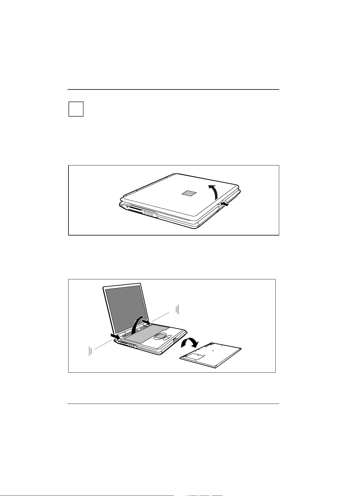
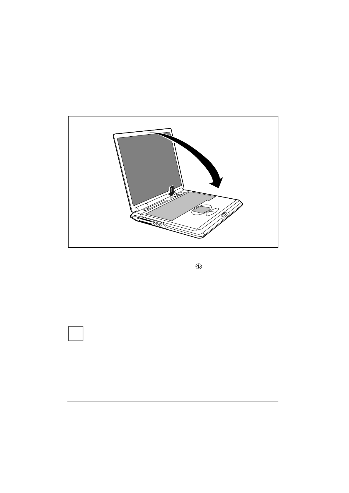
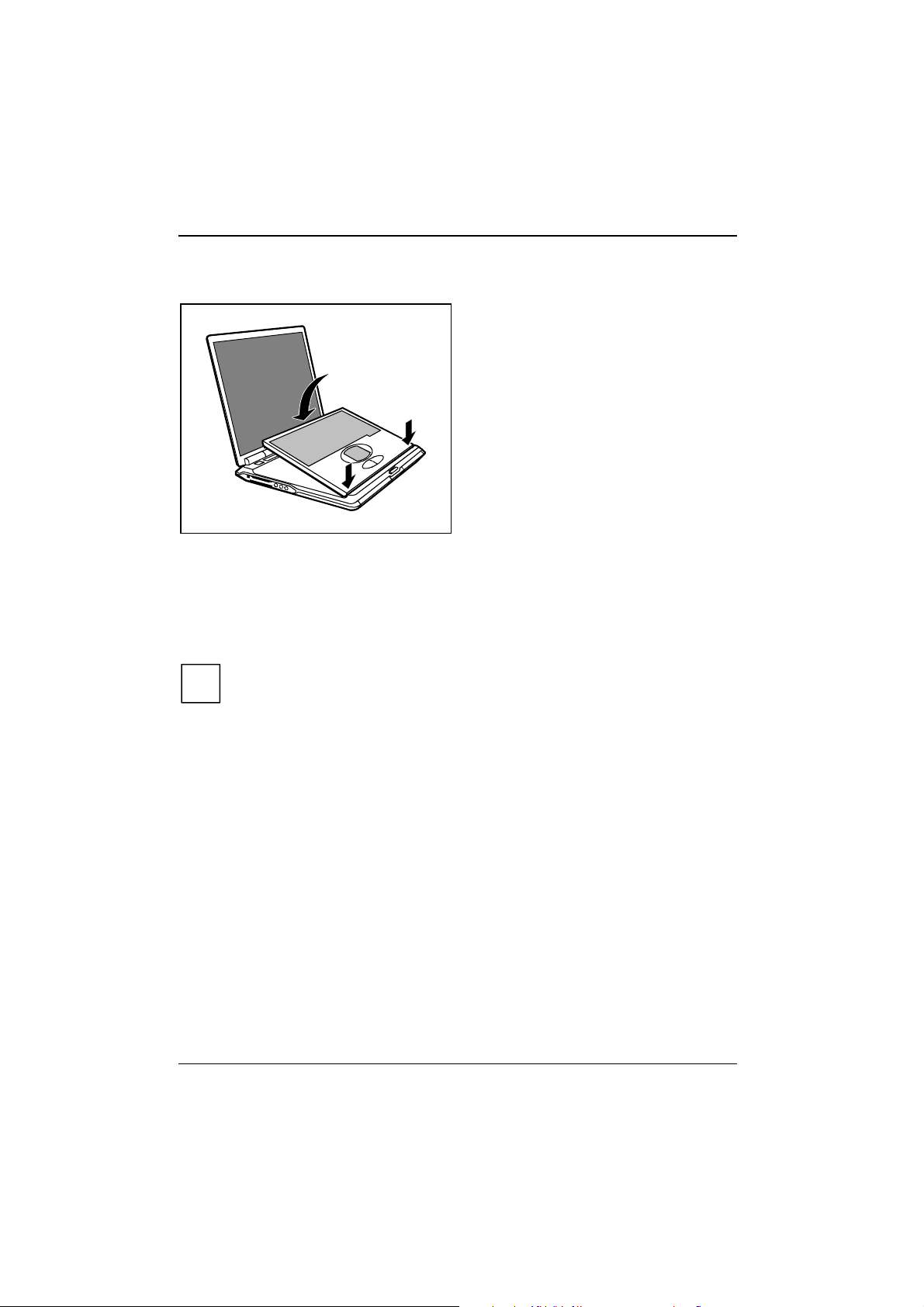
Ê Place the workstation on a flat, stable, nonslippery surface.
2
Ê Press the release button (1) and open the LED display panel (2).
1
Switching on removable radio keyboard
The ON/OFF switch of the radio keyboard is located on the underside of the keyboard.
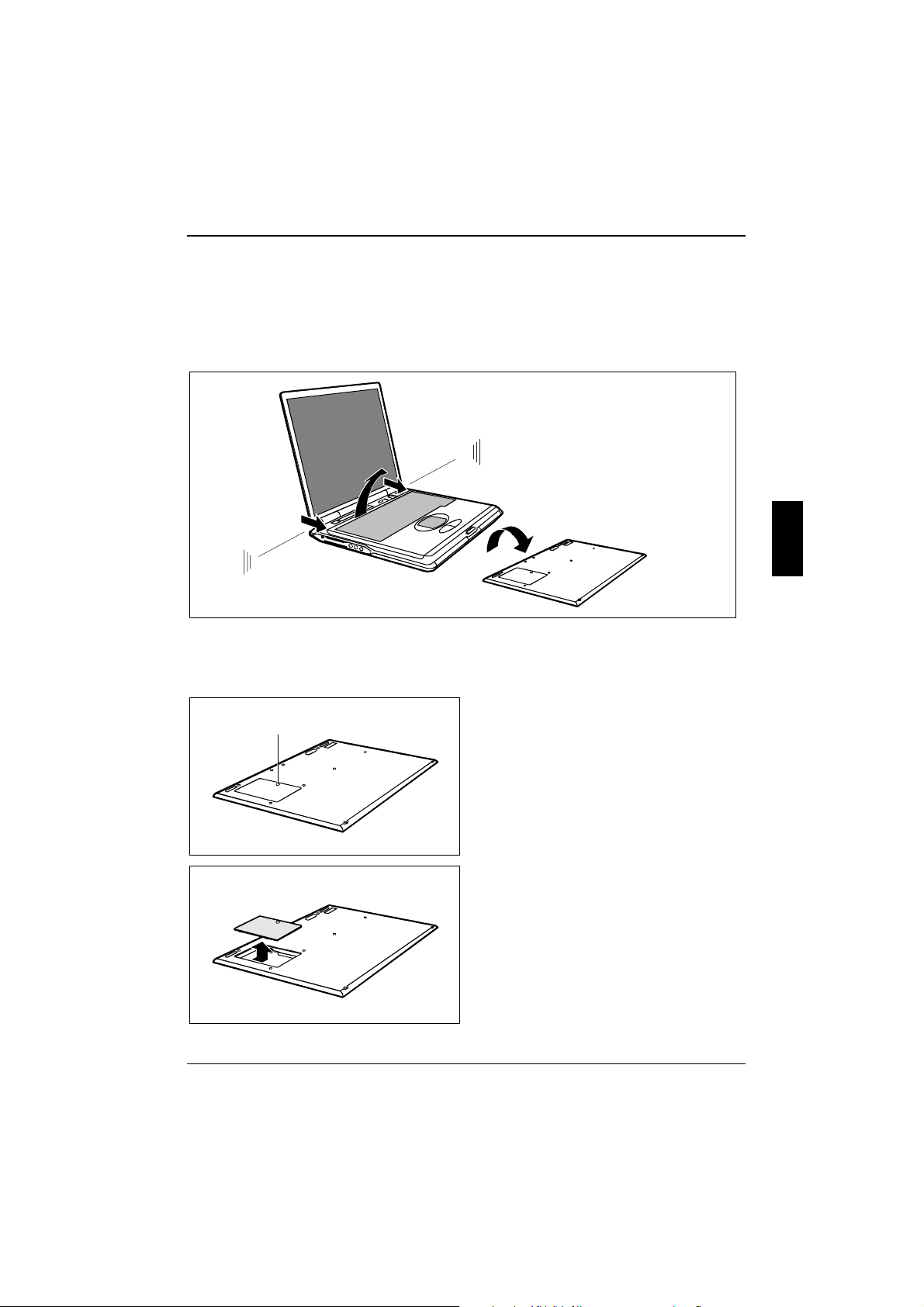
1
2
3
1
Ê Lift the keyboard at the two positions indicated (1).
Ê Remove the keyboard in the direction of the arrow (2).
12 A26391-K124-Z100-1-7619
Page 19
Preparing the workstation for use
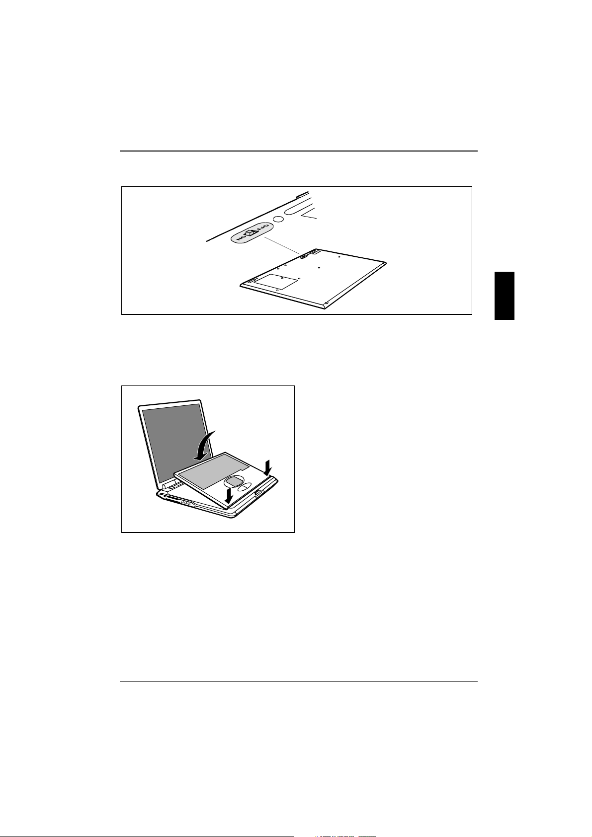
Ê Turn the keyboard over (3).
Ê Switch the keyboard on with the ON/OFF switch (ON).
The keyboard is permanently linked to the workstation by means of a wireless connection, if both
devices are switched on. The right-hand indicator on the keyboard lights as soon as a wireless
connection is established. No keyboard input is possible until the indicator lights. Occasionally it can
take up to 15 seconds to establish a connection (normally 2 to 5 seconds).
Ê Hold the keyboard at an angle and ensure
that the pins (1) fit into the matching
recesses.
The keyboard battery is being charged.
1
1
A26391-K124-Z100-1-7619 13
Page 20
Preparing the workstation for use
Connecting the power adapter and switching on the
workstation for the first time
When you switch on your workstation for the first time the supplied software is installed and
configured. You should plan some time for this, as this process must not be interrupted.
1
3
2
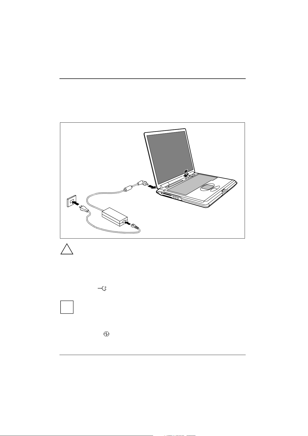
Use only the power adapter provided.
!
Ê Plug the DC output connector on the power adapter into the DC input connector (DC IN) on the
workstation (1).
Ê Connect the power cable to the power adapter (2).
Ê Plug the power cable into the mains supply (3).
The power indicator
recharged.
With the workstation switched on and off, the battery will completely recharge in
approximately three to four hours. Therefore you should leave the workstation connected
i
for some time even after completion of preparing for use.
Ê Press the Suspend/Resume button (4), and release it again.
The Suspend/Resume button functions like an ON/OFF switch.
The power-on indicator
14 A26391-K124-Z100-1-7619
on the workstation should illuminate. The workstation battery is being
on the workstation lights up.
Page 21

Preparing the workstation for use
After switch-on a self-test (POST, Power On Self Test) is automatically carried out. Never
switch the workstation off during the self-test.
!
Installing the software for the first time
Leave the external power adapter connected to your workstation during the initial
installation.
!
Once the installation has been started the workstation must not be switched off, unless
the installation has been completed.
During installation the workstation may only be rebooted when you are requested to do
so!
Ê During installation, follow the instructions on screen.
Consult the operating system manual if there is anything unclear about the requested input data.
You will find further information about the system, drivers, utilities, updates, manuals etc.
on the "CELSIUS Mobile Driver CD" supplied.
i
A26391-K124-Z100-1-7619 15
Page 22

Page 23
Working with the workstation
This chapter describes the basics for operating your workstation.
The chapter on "Connecting external devices" has instructions on how to connect external devices
(e.g. mouse, printer) to the workstation.
Please take note of the information in the chapter "Important notes".
!
Switching the workstation on
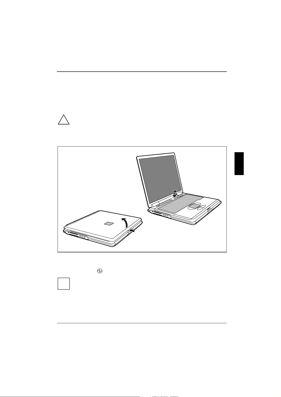
2
1
Ê Press the release button (1) and open the LED display panel (2).
Ê Press the Suspend/Resume button to switch on the workstation (3).
The power-on indicator
You can configure the Suspend/Resume button under Start - Settings - Control Panel -
Power Options - Power Options Properties.
i
If you have assigned a password, you must enter this when requested to do so, in order
to start the operating system password.
A26391-K124-Z100-1-7619 17
on the workstation lights up.
Page 24
Working with the workstation
Switching off the workstation
2
Ê Shut down the operating system properly.
If the workstation does not switch itself off, press the Suspend/Resume button (1) and hold it
down for approx. 4 seconds until the power-on indicator
The workstation is switched off.
Ê Close the LCD display of the workstation (2) so that it locks into place.
of the workstation goes out.
Switching off workstation via operating system
How you can switch off your workstation via the operating system is dependent on the settings of
the power-management feature. Additional information is contained in the section "Removing the
battery" in this chapter.
Save all open files before switching the workstation into the Standby mode to avoid data
loss when the workstation remains switched off for a longer time.
i
18 A26391-K124-Z100-1-7619
Page 25
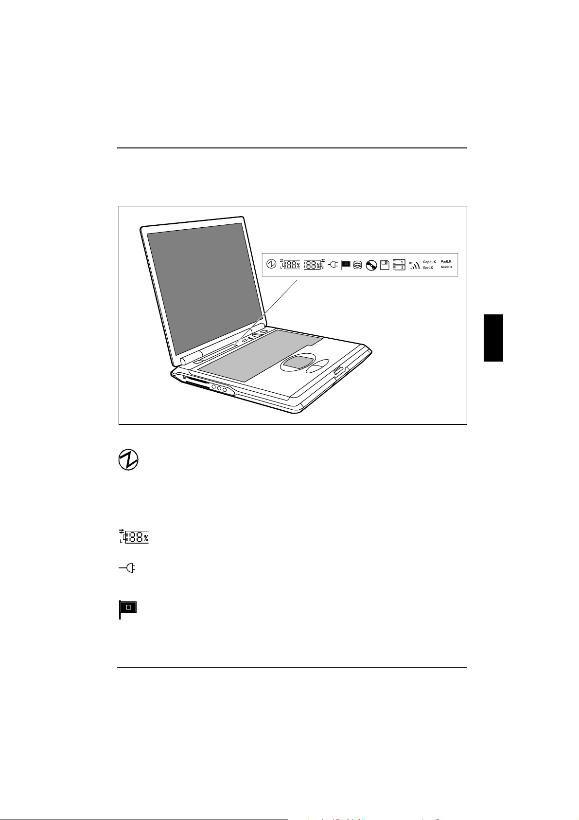
Indicators on the workstation
The following icons appear in the display field of your workstation:
Working with the workstation
The meanings of the symbols are as follows:
Power-on indicator
• The indicator lights up: The workstation is on.
• The indicator flashes (1 second on / 1 second off):
The workstation is in energy-saving mode.
• The indicator is dark:
The workstation is switched off.
Battery indicator
The battery charge state is indicated in the status indicator panel.
Power indicator
The power adapter is supplying power to the workstation.
"Speed Step" indicator
The indicator shows the processor performance (see key combination [Fn]
complete symbol lights up, when the processor performs at its best.
A26391-K124-Z100-1-7619 19
Fn] + [F5]
F5]). The
Fn]Fn]
F5]F5]
Page 26
Working with the workstation
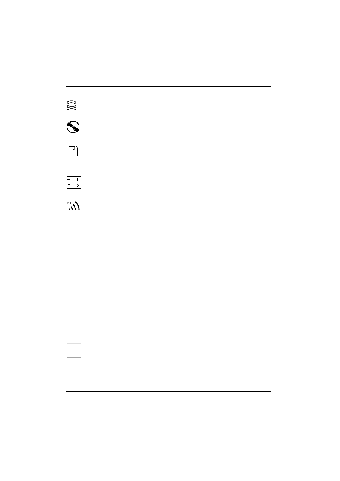
Hard disk indicator
The indicator lights up when the hard disk drive is being accessed.
Optical drive indicator
The indicator is lit when the CD/DVD in the optical drive is being accessed.
You must not remove the CD/DVD from the drive when this indicator is lit.
LS240 drive indicator
The indicator lights up when a floppy disk in the LS240 drive is being accessed.
You must not remove the floppy disk from the floppy disk drive when this indicator is
shown.
Indicator PC card 1 or 2
The indicator lights up when a PC card disk in slot 1 or 2 is being accessed.
You must not remove the PC card from the slot when this indicator is lit.
Indicator for radio connection to keyboard
The indicator lights up, when there is a radio connection between the keyboard and the
workstation.
If no keyboard cable is connected, input via keyboard and touchpad is possible only
when the indicator lights up.
CapsLK
ScrLK
PadLK
NumLK
20 A26391-K124-Z100-1-7619
CapsLK indicator (Caps Lock)
The ÏÏÏÏ key has been pressed. All the characters you type appear in uppercase. In the
case of overlay keys, the character printed on the upper left of the key appears when that
key is pressed.
Scroll indicator (Scroll Lock)
The [Scr]
[Scr] key has been pressed. The effect this key has varies from programme to
[Scr][Scr]
programme.
PadLK (Pad Lock) indicator
The [Num
[Num LK]
LK] key on the radio keyboard has been pressed. The numeric keypad on the
[Num[Num
radio keyboard is enabled.
NumLK indicator (Num Lock)
The [Num
the external keyboard is enabled.
A description of the indicators on the keyboard can be found in section "Operating the
removable radio keyboard" in this chapter.
i
LK] LK]
[Num LK]
LK] key on the external keyboard has been pressed. The numeric keypad on
[Num[Num
LK] LK]
Page 27
Working with the workstation
Operating the removable radio keyboard
Please take note of the safety information in the "Important notes" chapter.
!
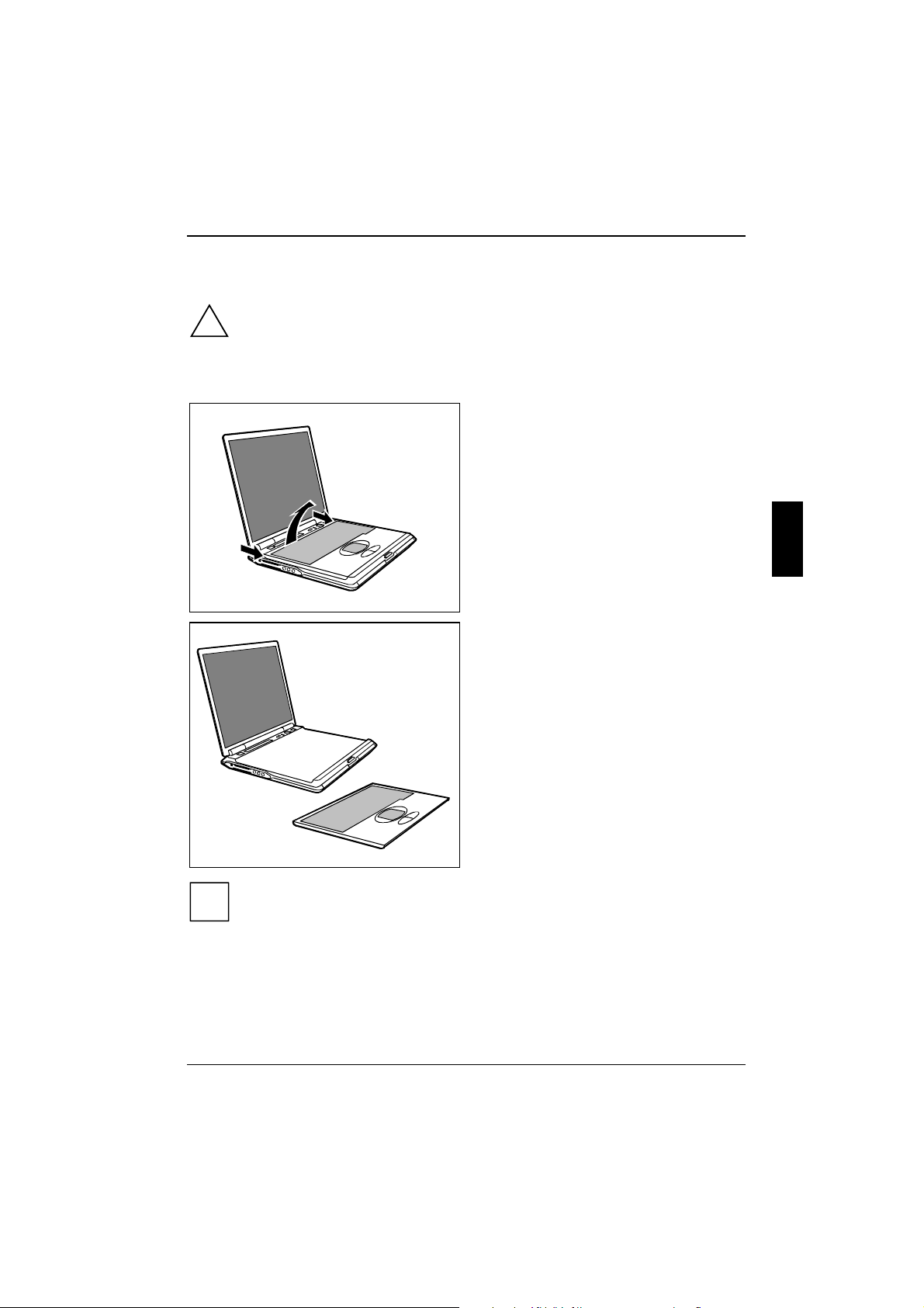
Removing the radio keyboard
Ê Lift the keyboard at the two positions
indicated (1).
Ê Remove the keyboard in the direction of the
arrow (2).
2
1
1
The keyboard is permanently linked to the
workstation by means of a wireless connection.
The right-hand indicator on the keyboard lights
as soon as a wireless connection is established.
No keyboard input is possible until the indicator
lights. Occasionally it can take up to 15 seconds
to establish a connection (normally 2 to
5 seconds).
If you are unable to establish a connection between the keyboard and the CELSIUS
Mobile Workstation, switch the keyboard off and then on again with the ON/OFF switch on
i
the underside of the keyboard.
A26391-K124-Z100-1-7619 21
Page 28
Working with the workstation
Attaching the radio keyboard
Ê Hold the keyboard at an angle and ensure
that the pins (1) fit into the matching
recesses.
1
1
Charging the keyboard battery
When the keyboard is attached to the workstation, the keyboard battery will be charged. The battery
indicator is on when the keyboard battery is charging.
The battery indicator flashes if the battery is low and the keyboard is removed. Re-attach the
keyboard so that the keyboard battery can recharge.
Place the keyboard on the device as often as possible so that the keyboard battery can
be charged.
i
If no power adapter is connected to the workstation, the keyboard battery will be charged
by the workstation battery. Even if the workstation is switched off, the keyboard battery is
charging and detracts energy from the workstation battery.
22 A26391-K124-Z100-1-7619
Page 29
Working with the workstation
Replacing the keyboard battery
The keyboard battery has a limited service life. If the battery indicator flashes soon after charging,
the keyboard battery has to be replaced.
You obtain the information on the appropriate battery type from your sales outlet or our
Hotline/Help Desk.
1
2
3
1
Ê Lift the keyboard at the two positions indicated (1).
Ê Remove the keyboard in the direction of the arrow (2).
Ê Turn the keyboard over (3).
Ê Open the battery compartment on the
1
underside of the keyboard.
Ê Lift the cover of the battery compartment.
A26391-K124-Z100-1-7619 23
Page 30
Working with the workstation
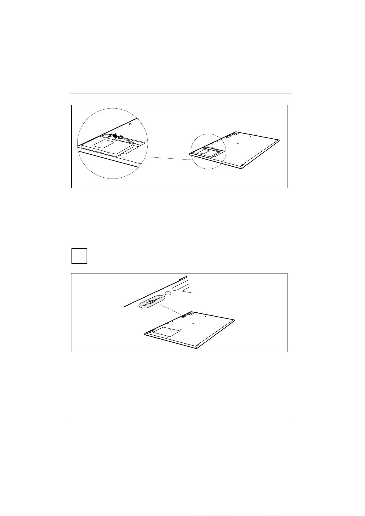
Ê Insert the new keyboard battery.
Ê Plug the connector of the keyboard battery into the connector in the battery compartment.
Ê Close the battery compartment.
Ê Re-attach the keyboard.
Switching the radio keyboard on and off
If you will not be using the radio keyboard, switch it off.
i
Ê Switch the keyboard ON or OFF with the ON/OFF switch on the underside of the keyboard.
24 A26391-K124-Z100-1-7619
Page 31

Working with the workstation
Operating the keyboard without a radio connection
For safety reasons you should not operate the keyboard with radio connection in some situations
(see "Safety" chapter).
You have to connect the keyboard to the workstation using the PS/2 cable supplied with your
workstation, if
• your are in an aircraft
• you are in a hospital
• the blue indicator for the radio connection on the keyboard does not light up.
1
2
Ê Plug one connector of the PS/2 cable supplied with your workstation to the port on the right
hand side of the keyboard.
Ê Plug the other connector into the PS/2 port of the workstation.
A26391-K124-Z100-1-7619 25
Page 32

Working with the workstation
Indicators on the keyboard
A 1
BT
22
CapsLK indicator (Caps Lock)
A
1
The Caps Lock key has been pressed. All the characters you type appear in uppercase.
In the case of overlay keys, the character printed on the upper left of the key appears
when that key is pressed.
Scroll indicator (Scroll Lock)
The [Scr]
[Scr] key has been pressed. The effect this key has varies from programme to
[Scr][Scr]
programme.
NumLK indicator (Num Lock)
The [Num
[Num LK]
LK] key on the external keyboard has been pressed. The numeric keypad on
[Num[Num
the external keyboard is enabled. The numbers on the lower left on keys in the integrated
numeric keypad are enabled.
Rechargeable battery indicator keyboard
Shows how much charge the keyboard battery has left.
LK] LK]
• The indicator lights up:
The keyboard battery is charging.
• The indicator flashes:
The keyboard battery is nearly empty.
Ê Place the keyboard on the workstation again to recharge the keyboard battery.
BT
Radio connection indicator
• The indicator lights up:
The radio connection is active.
If no keyboard cable is connected, input via keyboard and touchpad is possible only
when the indicator lights up.
26 A26391-K124-Z100-1-7619
Page 33

Working with the workstation
Description of keys
The keyboard of your workstation is subject to continuous wear due to normal use. The
keyboard markings are subjected to particularly high loads. The keyboard markings can
i
The following description of keys refers to Windows. Additional functions supported by the keys are
described in the relevant manuals supplied with your application programmes.
The figure below shows how to access the different characters on keys with overlaid functions. The
example applies when the CapsLK indicator is not lit.
wear off in the course of using the workstation.
&
7
½
7
&
7
½
7
Backspace key
The Backspace key deletes the character to the left of the cursor.
&
7
7
½
F11
Num
Scr
&
S
Fn
7
7
&
½
7
½
7
Tab key
The Tab key moves the cursor to the next tab stop.
Enter key (return)
The enter key terminates a command line. The command you have entered is
executed when you press this key.
Caps Lock key
The Caps Lock key activates uppercase mode (CapsLK indicator lit). The Caps
Lock function causes all the characters you type to appear in uppercase. In the
case of overlay keys, the character printed on the upper left of the key appears
when that key is pressed.
To cancel the Caps Lock function, simply press the Caps Lock key again.
Shift key
The Shift key causes uppercase characters to appear. In the case of overlay keys,
the character on the upper left of the keycap appears when that key is pressed.
Alt Gr
A26391-K124-Z100-1-7619 27
Alt Gr key
The [Alt
[Alt Gr]
Gr] key allows one to type the characters printed on the lower right of the
[Alt[Alt
Gr] Gr]
keycaps (e.g. { in the case of the [7]
[7] key on the German keyboard).
[7][7]
Page 34

Working with the workstation
Fn
Fn key
The [Fn]
[Fn] key enables the special functions indicated on overlay keys (see "Key
[Fn][Fn]
combinations").
If the external keyboard does not feature an [Fn]
the [Ctrl]
[Ctrl] + [Alt
[Ctrl][Ctrl]
Cursor keys
The cursor keys move the cursor in the direction of the arrow, i.e. up, down, left, or
right.
Break
Pause
Pause key
The [Pause]
[Pause] key temporarily suspends display output. Output will resume when you
[Pause][Pause]
press any other key.
Start key
The Start key invokes the Windows Start menu.
Menu key
The Menu key invokes the menu for the marked item.
Numeric keypad
&
½
7890
*
¾
()
UI OP
U
´
1
J
I
´
K
_
M
µ
[Alt Gr]
Gr] keys or the [Ctrl]
[Alt[Alt
Gr] Gr]
´
`
´
O Ö
L
:
0
;
<
>?
,
ç
.
/
[Ctrl] + [Alt]
[Alt] keys.
[Ctrl][Ctrl]
[Alt][Alt]
78
2
[Fn] key, you can simultaneously press
[Fn][Fn]
9
/
5
4
123-
0
x
6
,
++++
1 = Characters enabled when NumLK indicator is not lit (see "Indicators on the keyboard").
2 = Characters enabled when NumLK indicator is lit (see "Indicators on the keyboard").
If the numeric keypad is enabled (NumLK indicator is lit) and you hold down the [Fn]
[Fn] key, you can
[Fn][Fn]
output the characters printed in blue on the bottom right of the keys.
Key combinations
The following description of key combinations refers to functions when using Microsoft Windows.
Some of the following key combinations may not function in other operating systems and with some
device drivers.
Other key combinations are described in the relevant manuals supplied with your application
programmes.
Key combinations are performed as follows:
Ê Press and hold the first key in the combination.
28 A26391-K124-Z100-1-7619
Page 35

Working with the workstation
Ê While holding the first key down, press the other key or keys in the combination.
If the external keyboard does not feature an [Fn]
the [Ctrl]
[Ctrl] + [Alt
[Alt Gr]
i
Fn
[Ctrl][Ctrl]
F1
+
Gr] keys or the [Ctrl]
[Alt[Alt
Gr] Gr]
Connecting keyboard and workstation ("Pair")
This key combination "acquaints" keyboard and workstation (function
[Ctrl] + [Alt]
[Ctrl][Ctrl]
[Fn] key, you can simultaneously press
[Fn][Fn]
[Alt] keys.
[Alt][Alt]
"Pair", preset at the factory). You need this key combination only when you
have to replace the keyboard supplied with your workstation by a new one.
F2
+
Fn
Undocking
This key combination prepares the workstation for undocking from the Port
Replicator.
F3
+
Fn
Enlarge MS-DOS screen
This key combination enlarges the screen in the MS-DOS mode to the fullscreen mode or switches it back to the normal display mode.
F4
+
Fn
Switch internal touchpad on/off
This key combination enables and disables the touchpad function.
To do this, set the setting Internal Pointing Device to Auto Disabled in the
BIOS Setup in the menu Advanced - Keyboard/Mouse Features.
F5
+
Fn
Switch Speed Step mode on
This key combination switches between the possible Speed Step modes:
− Maximum power
− Battery-optimised power (reduced process speed in battery
mode)
F6
+
Fn
Switching the loudspeakers on/off
This key combination switches your device's integrated loudspeakers off
and on.
F7
+
Fn
Increasing the volume
This key combination raises the volume of the integrated loudspeakers.
F8
+
Fn
F10
+
Fn
Reducing the volume
This key combination reduces the volume of the integrated loudspeakers.
Switching between internal and external screen
If an external monitor is connected, the monitor on which the output is to be
displayed can be selected with this key combination. You can opt to use:
• just the workstation's LCD screen
• just the external monitor
• both the LCD screen and the external monitor.
F11
+
Fn
F12
+
Fn
A26391-K124-Z100-1-7619 29
Increasing screen brightness
This key combination increases screen brightness.
Decreasing screen brightness
This key combination decreases screen brightness.
Page 36

Working with the workstation
Backtab (Shift+Tab)
This key combination moves the cursor back to the previous
tabular stop.
Carrying out a warm boot
Warm boot
This key combination restarts the workstation. First hold down the
[Ctrl]
[Ctrl] and [Alt]
[Ctrl][Ctrl]
Windows 98, Windows 2000, Windows Me, Windows XP and
Windows NT the Task Manager appears first. Then you must press
all three keys again to re-boot.
[Alt] key, and then press the [Del]
[Alt][Alt]
[Del] key. Under
[Del][Del]
Ctrl
+
Alt Del
Touchpad and touchpad buttons
The touchpad enables you to move the mouse pointer on the screen. The two touchpad buttons
allow the selection and execution of commands. They correspond to the buttons on a conventional
mouse.
1
2
1 = Touchpad 2 = Touchpad buttons
Moving the pointer
Ê Move your finger evenly across the touchpad.
Selecting
Ê Tap the touchpad once or press the left button once.
Executing a command
Ê Tap the touchpad twice or press the left button twice.
30 A26391-K124-Z100-1-7619
Page 37

Working with the workstation
Dragging an object
Ê Move the pointer to the item you wish to select.
Ê Select the desired object, and leave your finger on the touchpad.
Ê Drag the object to the desired position.
Ê Lift your finger from the touchpad.
LCD display panel
Information on LCD monitor
High-quality TFT monitors are installed in CELSIUS Mobile H workstations from Fujitsu Siemens
Computers GmbH. The specification of the monitor resolution indicates how many pixels can be
displayed. For example, "UXGA" stands for 1600 x 1200 pixels. Each pixel consists of three socalled subpixels of the colours red, green and blue. As a result, a UXGA monitor consists of
1600 x 1200 x 3 = 5.760.000 subpixels.
The standard of production techniques today cannot guarantee an absolutely fault-free monitor. A
few isolated constant lit or unlit pixels may be present. To ensure the highest possible quality,
Fujitsu Siemens Computers uses only monitors that at least comply with the standard
DIN ISO 13406-2 (Class III).
TFT monitors are operated with background lighting. The luminosity of the background lighting can
decrease during the period of use of the monitor. The brightness of your monitor can be set
individually with the brightness control keys of the keyboard.
Display settings
Setting the desktop area
You can change the screen resolution under Start - Settings- Control Panel - Display - Settings and then
selecting from the Resolution field.
Adjusting the font size
Under Start - Settings - Control Panel - Display - Settings you can choose between a larger and a
smaller font in the Font size field.
Adjusting the speed of the mouse pointer
You can change the speed of the mouse pointer under Start - Settings - Control Panel - Mouse and
clicking on the Motion tab.
Setting the display brightness
You can adjust the brightness of your LCD screen with the keys [Fn]
With [Fn]
[Fn] and [F12]
[Fn][Fn]
Synchronising the display on the LCD screen and an external monitor
Your workstation supports the simultaneous display on the LCD monitor and an external monitor. If
the picture does not appear correctly on the LCD monitor, press the key combination [Fn]
several times, or switch the external monitor off and then on again. This achieves good picture
synchronisation.
A26391-K124-Z100-1-7619 31
[F12], screen brightness will be reduced and with [Fn]
[F12][F12]
[Fn] and [F12]
[Fn][Fn]
[Fn] and [F11]
[Fn][Fn]
[F12] or [Fn]
[F12][F12]
[F11] increased.
[F11][F11]
[Fn] and [F11]
[Fn][Fn]
[F11]:
[F11][F11]
[Fn] + [F10]
[F10]
[Fn][Fn]
[F10][F10]
Page 38

Working with the workstation
Battery
The battery is one of the most important components of your workstation. When not plugged into a
mains outlet, the workstation runs on its built-in battery. You can increase the life of the battery by
caring for the battery properly. The average battery life is around 500 charge/discharge cycles.
You can extend the battery life by taking advantage of the available energy saving functions.
You should use only batteries identified by the number P/N S26391-F300-V210. Only
these batteries are released for use with your workstation.
!
Take care not to drop the batteries or otherwise damage their casing (fire risk).
If the rechargeable batteries are defective, they must not be used.
Do not touch the contacts of the batteries.
Never interconnect the positive and negative terminals of a battery.
Used batteries must be disposed of in accordance with local regulations (special waste).
Observe the information on battery storage in the chapter "Important notes".
Performing the battery learning cycle
The battery contains electronics that continuously monitor the battery charging level and display the
current charging level. To compensate for measuring errors in the electronics, and because the
chemical properties of the battery change over time, the electronics must be recalibrated regularly.
This calibration is carried out using a battery learning cycle. Using the battery learning cycle ensures
that the maximum battery capacity can always be used. During the learning cycle a defined charging
cycle is carried out.
The battery learning cycle lasts between four and six hours and must not be aborted.
During this period you can not work with the workstation!
i
Ê Restart the workstation (switching On/Off or warm boot).
The following display briefly appears on the screen during start-up:
<ESC> Diagnostic screen <F12> Boot Menu <F2> BIOS Setup <F6> Battery
learning
Ê Press function key [F6]
The learning cycle is started. When the learning cycle is ended, a corresponding message is
displayed.
32 A26391-K124-Z100-1-7619
[F6].
[F6][F6]
Page 39

Working with the workstation
Charging the battery
The battery indicator displays the remaining battery charge (see the chapter "Indicators on the
workstation"). When you switch on the workstation, it takes a few seconds before the battery status
is displayed.
You can charge the battery by connecting the workstation to the power adapter (see "Connecting
the power adapter and switching on the workstation for the first time").
The battery can only be charged when the ambient temperature is between 5°C and max. 35°C.
With the workstation switched on and off, the battery will completely recharge in approximately three
to four hours.
Work in the battery mode until an acoustic warning prompts you to recharge and the battery
indicator begins to flash. The workstation battery should not be charged before this point.
If you do not connect the power adapter within five minutes of the signals described above, your
workstation automatically switches itself off.
Monitoring the battery charging level
The remaining battery charge is indicated by the battery symbol in the status indicator panel (see
the chapter "Indicators on the workstation"). When you switch on the workstation, it takes a few
seconds before the battery status is displayed.
During mobile operation you can also use a "battery charge meter" for energy-saving monitoring
under Windows.
A battery icon is shown in the taskbar. When you place the mouse pointer on the battery symbol,
the system displays the battery status.
You can also see the battery's charging state on
the battery itself.
100 80
60 40 20
There are five indicators next to the finger icon
on the battery telling you what percentage of the
battery is charged.
Ê Press the finger icon.
The corresponding indicator lights up.
If no power adapter is connected to the workstation, the keyboard battery will be charged
by the workstation battery. Even if the workstation is switched off, the keyboard battery is
i
charging and detracts energy from the workstation battery.
Inserting and removing the battery
Only use batteries released for this workstation.
!
Never use force when inserting or removing a battery.
Make sure that no foreign objects enter the slots.
Ê Switch off the workstation.
Ê Place the workstation on a flat surface.
Ê Open the LCD display panel.
A26391-K124-Z100-1-7619 33
Page 40

Working with the workstation
Removing the battery
1
2
Ê Push the slide in the direction of the arrow (1) up to the stop and hold it in place.
Ê Pull the battery out of the casing in the direction of the arrow (2).
34 A26391-K124-Z100-1-7619
Page 41

Working with the workstation
Installing the battery
1
2
Ê Push the slide in the direction of the arrow (1) up to the stop and hold it in place.
Ê Position the battery at the edge of the casing (2) and then press it into the workstation.
A26391-K124-Z100-1-7619 35
Page 42

Working with the workstation
r
Using the power-management features
The workstation uses less power when the power management features are enabled. You will then
be able to work longer when using the battery before having to recharge it.
If you are connected to a network or use the integrated modem, PC LAN card, or PC
modem card, we advise against enabling an energy saving mode. This could lead to an
i
interruption of your network connection.
When not using the workstation for long periods of time, first end the energy saving mode,
then switch off the workstation. Never switch off the workstation with the
Suspend/Resume button while the workstation is in one of the energy-saving modes.
If your workstation is in an energy-saving mode:
• Do not connect any external devices.
• Do not disconnect any external peripheral devices.
• Do not attempt to switch the workstation on if the built-in battery is flat.
• Do not change or remove the floppy disk, if inserted.
• Do not add or remove RAM.
• Do not add or remove a PC card.
• Do not replace or remove the battery.
Energy-saving modes of workstation
You can set two energy-saving modes with your workstation.
In the Suspend mode (Suspend to DRAM/Standby) all current data (active programmes, files) are
buffered in the main memory, and in the Save-to-Disk mode (Save to Disk/HibernateMode) all current
data are saved on the hard disk. Then the workstation is switched off. After the workstation is
switched on, you can continue working exactly where you left off before.
Operating systems with ACPI
(Windows 2000 and Windows XP)
For operating systems with ACPI you can set the energy-saving functions under Settings -
You can configure the Suspend/Resume button and the lid switch in the Settings tab unde
Settings – Control Panel – Power Management.
Control Panel - Power Management (e.g. Standby, Hibernate mode and LCD off).
i
Settings for energy-saving functions in the BIOS Setup are not taken into account by
operating systems with ACPI.
36 A26391-K124-Z100-1-7619
Page 43

Working with the workstation
Changing settings
Ê Double-click on the My Computer symbol.
Ê Double-click on the Control Panel symbol.
Ê Double-click on the Power management symbol in the Control Panel window.
The Properties dialogue field appears.
Ê Adjust the setting to your needs.
Ê Click on OK to save the settings.
Under Windows 2000 the Hibernate mode is switched off in the default setting.
i
Hard disk
The hard disk is the most important storage medium of your workstation. You can work considerably
faster and more efficiently if you copy applications and files from floppy disks or CDs to your hard
disk.
When the hard disk is accessed, the hard disk indicator lights up.
Inserting and removing modules
Modules can be optical drives, additional hard disk or floppy disk drives or batteries.
Only use modules released for this workstation.
!
Do not use force when installing or removing a module.
Make sure that no foreign objects enter the slots.
Ê Switch off the workstation.
Ê Place the workstation on a flat surface.
Ê Open the LCD display panel.
A26391-K124-Z100-1-7619 37
Page 44

Working with the workstation
Removing modules
1
2
Ê Push the slide in the direction of the arrow (1) up to the stop and hold it in place.
To remove the left-hand module, push the slide to the right. To remove the right-hand
module, push the slide to the left.
i
Ê Remove the module the direction of the arrow (2).
38 A26391-K124-Z100-1-7619
Page 45

Working with the workstation
Installing modules
1
2
Ê Push the slide in the direction of the arrow (1) up to the stop and hold it in place.
To install the left-hand module, push the slide to the right. To install the right-hand
module, push the slide to the left.
i
Ê Position the module at the edge of the casing (2) and then press it into the workstation.
Ê Release the slide (2).
A26391-K124-Z100-1-7619 39
Page 46

Working with the workstation
Optical drives
Your workstation is fitted with a combo drive (CD-RW/DVD).
This device contains a light-emitting diode, classified according to IEC 825-1:1993:
LASER CLASS 1, and must not be opened.
!
Avoid touching the surface of a CD/DVD. Handle CDs/DVDs only by their edges!
Always store CDs/DVDs in their cases. Thus you avoid dust contamination, scratches,
bending or other damage.
Protect your CDs/DVDs from dust, mechanical vibration and direct sunlight!
Avoid storing a CD/DVD in areas subject to high temperatures or humidity.
You may use both 8-cm and 12-cm CDs/DVDs in the optical drive.
When using CDs/DVDs of poor quality vibrations and reading errors may occur.
Optical drive indicator
The indicator flashes when a CD/DVD is inserted. The indicator goes out when the drive is
ready-to-operate. The indicator lights up when the drive is accessed.
If the indicator does not go out after the CD/DVD is inserted, and continues to flash, the
CD/DVD is probably damaged or dirty.
i
Inserting or removing a CD/DVD
The workstation must be switched on.
Ê Push the insert/eject button.
The drive tray will open.
Ê Pull the drive tray completely out.
Ê Place the CD/DVD in the drive tray with the label facing upwards.
or
Ê Take out an inserted CD/DVD.
Ê Push in the drive tray until you feel it lock into place.
Manual removal (emergency removal)
In the event of a power failure or damage to the drive it may be necessary to manually remove the
CD/DVD.
Ê Switch off the workstation.
Ê Push a pen or a piece of wire (such as a paper clip) into the opening for manual ejection.
The drive tray is unlocked. You can now pull the drive tray out of the drive.
40 A26391-K124-Z100-1-7619
Page 47

LS240 drive (floppy disk drive)
Never clean the floppy disk drive with cleaning disks. Any attempt would destroy the
read/write head in the disk drive within 20 seconds.
!
Working with floppy disks
Follow the instructions supplied by the vendor of the floppy disks.
i
5
Working with the workstation
4
1
2
3
1 = Insertion direction
2 = Label area
3 = Write protection tab for a 1.44 Mbyte floppy disk
4 = Identification of a 1.44 MB floppy disk or write protect switch on a 120 MB floppy disk
5 = Eject button for inserted floppy disks
6 = Disk is write-protected
7 = Disk is not write-protected
To insert a diskette:
Ê Push the floppy disk into the drive in the insertion direction (1) until it engages. The label
should be facing upward.
To remove a diskette:
Ê Push the eject button (5).
Protect the floppy disk against being overwritten or erased
Ê Slide the write-protect slider into position (6). The hole is now visible.
Deactivate write protection
Ê Slide the write-protect slider into position (7). The hole is now covered.
6
7
A26391-K124-Z100-1-7619 41
Page 48

Working with the workstation
56k-Modem
A modem is already installed in your workstation. The 56k modem supports all data communication
applications, such as:
• Modem operation: High-speed downloads at up to 56,000 bit/s (V.90). Downward-compatible to
V.34 modems.
• Fax mode: Transmitting and receiving at up to 14,400 bit/s
• Simple country adaptation with programme
The modem complies with the EU Directive 91/263/EEC (Telecommunications terminal equipment
directive) and has been checked in agreement with the guideline TBR-21.
The modem can be operated in the following countries:
Multifrequency (MFC) dialling
Belgium, Denmark, Germany, Finland, France, Greece, Great Britain, Holland, Ireland, Iceland,
Italy, Luxembourg, Norway, Austria, Portugal, Sweden, Switzerland and Spain.
Pulse dialling:
Belgium, France, Holland and Italy.
Also in: Poland, Slovenia, South Africa and Hungary.
Connecting workstation modem to telephone connection
3
1
2
Ê Connect the modem cable supplied to the country-specific telephone adapter (1).
Ê Connect the modem cable to the modem port of the workstation (2).
Ê Connect the modem cable to your telephone wall socket (3).
42 A26391-K124-Z100-1-7619
Page 49

Working with the workstation
If you attach your modem on a TAE-N-connector the phone respectively data cable is
busy. The cable cannot be used for other communication devices at the same time. Pull
i
the modem plug out of the TAE-N-power socket after the data transfer, because also with
connected cable no other communication devices can be used.
Connecting the workstation to Ethernet/LAN
An Ethernet LAN card is already installed in your workstation.
2
1
Ê Connect the LAN cable to the LAN port of the workstation (1).
Ê Connect the LAN cable to your LAN connector.
A26391-K124-Z100-1-7619 43
Page 50

Working with the workstation
Connecting IEEE1394 (FireWire)
Your workstation is equipped with an IEEE1394 (FireWire) connection, which operates at 400 Mbit
per second, as an option. Peripheral devices such as digital audio/video devices or other high-speed
devices can be connected via IEEE1394 (FireWire).
1
Ê Connect the peripheral device to the IEEE1394 (FireWire) (1) port of your workstation.
44 A26391-K124-Z100-1-7619
Page 51

Working with the workstation
PC cards
Two PC card slots enable the device to operate two type II PC cards or one type III PC card
(CardBus or PCMCIA).
Installing a PC card
Consult the documentation supplied by the PC card's manufacturer and follow the
instructions provided.
!
Never use force when inserting or removing a PC card.
Make sure that foreign objects do not fall into the PC card slot.
Ê Insert the PC card, contacts first, into the lower slot guide. The labelled side of the PC card
should be facing upward.
Ê Gently push the PC card into the slot until you feel it click into place.
Consult the documentation supplied with the PC card for information on how to install the
necessary device drivers.
i
For further information refer to the information files (e.g. *.TXT, *.DOC, *.WRI or *.HLP)
provided on the PC card driver diskette or the information in the operating system manual.
You can push the PC card slot eject buttons down flush into the case. Press the eject
buttons until they snap in.
A26391-K124-Z100-1-7619 45
Page 52

Working with the workstation
Removing a PC card
2
1
Ê Press the eject button (1). It will project further out of the workstation's case. If the eject buttons
are pushed in flush with the workstation casing, they must first be snapped out. Press the eject
buttons until they snap out.
Ê Slide the PC card out of the workstation (2).
46 A26391-K124-Z100-1-7619
Page 53

Working with the workstation
Microphone and loudspeakers
1
2
1 = Built-in microphone 2 = Built-in loudspeakers
Your workstation contains a built-in microphone (1) and two loudspeakers (2).
If you attach an external microphone, the built-in microphone is disabled. The internal loudspeakers
switch off when you attach headphones or external loudspeakers to the audio jack.
A26391-K124-Z100-1-7619 47
Page 54

Page 55

Security functions
Your workstation enables you to protect your system and personal data against unauthorised
access in a number of ways. By combining these options, you can achieve maximum protection for
your system.
In this chapter you will learn which security functions your workstation is equipped with, which
advantages these functions offer you and how to configure and use them.
Passwords must be assigned for some security functions. Please be sure to note these
passwords, as otherwise you will no longer be able to access your system.
!
We recommend that you make a note of the passwords and keep them in a safe place.
If you lose both the user and the supervisor passwords, you must contact our Help Desk.
The phone numbers can be found in the "Safety" manual. The loss of passwords is not a
warranty case and is therefore subject to charge.
Overview of all security functions
The following sections contain a brief description of the security functions that are provided with your
workstation as standard equipment.
Kensington Lock
With the Kensington MicroSaver, a sturdy steel cable, you can protect your workstation from theft.
For this reason your workstation is equipped with a device for the Kensington MicroSaver. The
Kensington MicroSaver is available as an accessory.
Password protection
You can protect you personal data from unauthorised access with various passwords. By combining
these different options, you can achieve maximum protection for your system.
Password protection for the BIOS Setup
With the Supervisor password you prevent unauthorised opening of the BIOS Setup, and with it
access to important system settings. In the BIOS Setup you can also activate protection for the
operating system and your hard disk.
Password protection for the operating system
With corresponding settings in the BIOS Setup you can block starting of the operating system. Only
those who know the supervisor or user password can access the system.
Password protection for your hard disk
By activating the hard disk protection in the BIOS Setup you prevent unauthorised access to the hard
disk drive. The hard disk password is checked internally during each system start-up and ensures
that the hard disk can only be used in conjunction with the related device.
A26391-K124-Z100-1-7619 49
Page 56

Security functions
SmartCard reader
Your workstation also allows operation of a SmartCard via the SmartCard slot. The SmartCard can
be used as a particularly secure alternative or as an addition to password protection. SmartCards
are just as useful for digital signatures or for encrypting e-mails.
You can also read out other cards with your SmartCard reader (e.g. cell phone cards, health
insurance cards, bank cards). For this purpose you also require the software matched to the
respective card.
Fingerprint sensor
Your workstation is equipped with a fingerprint sensor. You can use the fingerprint sensor as an
alternative to the BIOS password as system protection. By the way you can use the fingerprintsensor under any operating system.
Brief overview of the security functions
Security function Type of protection Preparation
Kensington Lock Mechanical Mount and lock Kensington
BIOS password protection Password protection for BIOS
Setup, operating system and
hard disk with Supervisor and
User password. The passwords
consist of a maximum of eight
alphanumeric characters.
SmartCard Protection of the operating
system with PIN and
SmartCard on which a "Public
Key" or a password is stored.
Fingerprint sensor Protection of BIOS Setup,
operating system and hard disk
by registered fingerprint.
MicroSaver (accessory)
Specify at least one Supervisor
password in the BIOS Setup and
activate the password
protection for the operating
system and hard disk as
desired.
Obtain SmartCard (accessory),
install appropriate software, e.g.
Smarty (accessory). Specify a
password when using the
Smarty software.
Activate fingerprint sensor in
BIOS Setup and register
fingerprint.
50 A26391-K124-Z100-1-7619
Page 57

Using Kensington Lock
a
Ê Fit the Kensington MicroSaver on the device (a) on your workstation.
Security functions
Configuring password protection in BIOS Setup
Passwords can be up to eight characters long. You can use all alphanumeric characters
and need not distinguish between uppercase and lowercase characters.
i
Before you exploit the various options of the password protection for your data security in
the BIOS Setup, please note the following points:
!
Please keep in mind your passwords in any case, as you will not be able to access your
BIOS Setup and/or your system any longer, if you forget both the user password and the
supervisor password. Deletion of passwords at the factory is not a warranty case and is
therefore subject to charge.
Please care for a regular data backup on external data carriers!
A26391-K124-Z100-1-7619 51
Page 58

Security functions
Protecting BIOS Setup (supervisor and user password)
We recommend that you print out the following instructions, as these cannot be displayed while
setting the password.
You prevent unauthorised opening of the BIOS Setup with both the supervisor and the user
password. With the supervisor password you have access to all functions of the BIOS Setup, and
with the user password only to part of the functions. You can only set a user password if a
supervisor password has already been assigned.
Set the supervisor and user password
Ê Call BIOS Setup and select the Security menu. Please refer to section "Settings in BIOS Setup"
for a description of operating the BIOS Setup.
You always move within the BIOS Setup with the cursor keys.
i
Ê Mark the Set Supervisor Password field and press the Enter key.
With Enter new Password: you are then requested to enter a password.
Ê Enter the password and press the Enter key.
With Re-Enter new Password you are asked to confirm the password.
Ê Enter the password again and press the Enter key.
With Notice: Changes have been saved you receive a confirmation that the new password has been
saved.
Ê To assign the user password, mark the field Set User Password and proceed exactly as when
configuring the supervisor password.
If you do not want to make any other settings, you can exit BIOS Setup.
Ê Select the Exit Saving Changes option in the Exit menu.
The workstation is rebooted and the new password is effective. If you now want to open the BIOS
Setup, you must first enter your supervisor or user password. Please note that you only have access
to a few BIOS settings with the user password.
Change supervisor or user password
Ê When changing the password, proceed exactly as for password assignment.
You can only change the supervisor password when you have logged into the BIOS Setup with the
supervisor password.
Cancelling password
To cancel a password (without setting a new password) run the following steps:
Ê Call BIOS Setup and select the Security menu.
Ê Mark the Set User Password or Set Supervisor Password field and press the Enter key.
With Enter new Password you will then be asked to enter a password.
Ê Press the Enter key twice.
Ê Select the Exit Saving Changes option in the Exit menu.
52 A26391-K124-Z100-1-7619
Page 59

Security functions
The workstation is rebooted and the password is cancelled.
Cancelling the supervisor password invalidates the user password at the same time.
Password protection of operating system
With the supervisor password or the user password, which you have assigned in the BIOS
Setup (see the Section "Entering supervisor and user password"), you can also block
i
booting of the operating system.
Activating system protection
Ê Call BIOS Setup and select the Security menu.
Ê If you have not assigned BIOS passwords yet, you now specify the supervisor and the user
password, if desired (see section "Set the supervisor and user password").
Ê Mark the Password on Boot field and press the Enter key.
Ê Select the Every Boot entry and press the Enter key.
If you do not want to make any other settings, you can exit BIOS Setup.
Ê Select the Exit Saving Changes option in the Exit menu.
The workstation reboots and you are asked to enter your password (the supervisor or user
password).
Deactivating system protection
Ê Call BIOS Setup and select the Security menu.
Ê Mark the Password on Boot field and press the Enter key.
Ê Select Disabled and press the Enter key.
If you do not want to make any other settings, you can exit BIOS Setup.
Ê Select the Exit Saving Changes option in the Exit menu.
The workstation reboots and there is no longer any password protection for the operating system.
Password protection for hard disk
The had disk password prevents unauthorised access to the hard disk drives and is
checked internally each time the system is booted. The condition for this is that you have
i
assigned at least the supervisor password.
Activating hard disk protection
Ê Call BIOS Setup and select the Security menu.
If you have not assigned BIOS passwords yet, define the supervisor and the user password now, if
desired (see section "Protecting BIOS Setup (supervisor and user password)").
A26391-K124-Z100-1-7619 53
Page 60

Security functions
You can set hard disk protection separately for each hard disk (for the internal and the two optional
hard disks).
Internal Hard Disk Security Hard disk protection for the internal hard disk
Left Bay Security Hard disk protection for the hard disk in the left bay
Right Bay Security Hard disk protection for the hard disk in the right bay
Ê Highlight the appropriate field and select Enabled.
Note that protection of optional hard disks applies to the selected bay in which the hard
disk is inserted. If you enable hard disk protection for only one of the bays, the other bay
i
is not protected. In other words, if you swap the hard disk in the protected bay to the
unprotected bay, hard disk protection for the hard disk is cancelled.
If you do not want to make any other settings, you can exit BIOS Setup.
Ê Select the Exit Saving Changes option in the Exit menu.
The workstation reboots and your hard disk is now protected with a password.
Deactivating hard disk protection
Ê Call BIOS Setup and select the Security menu.
Ê Mark the Hard Disk Security field and select the Disabled entry.
If you do not want to make any other settings, you can exit BIOS Setup.
Ê Select the Exit Saving Changes option in the Exit menu.
The workstation restarts.
Configuring and using SmartCard reader
Your workstation is equipped with a SmartCard slot and a special chip to read your SmartCards.
SmartCards
SmartCards are not supplied as standard equipment. You can use all SmartCards that comply with
ISO Standard 7816-1, -2, -3 or -4 and are PC SC-compatible. These SmartCards are available from
various manufacturers. Under Windows 2000 or Windows XP we recommend the SICRYPT card, as
the drivers for this SmartCard are already preinstalled under Windows 2000 and Windows XP.
With the appropriate software you can use your SmartCard as an alternative to password protection,
but also as a digital signature or for encrypting your e-mails.
With the security software Smarty (available as an accessory) you can assign a password to your
SmartCard. This enables you to safely log on to the operating system under Windows 2000 and
under Windows XP.
We recommend that you always use two SmartCards. Always keep one of the SmartCards in a safe
place if you carry the other SmartCard with you.
The SmartCard can only be used with a PIN so protection is maintained even when the
SmartCard is lost. After the incorrect PIN is entered three times, the card is blocked.
i
The first time you use your SmartCard you must enter the preset PIN provided by the
SmartCard manufacturer or your system administrator.
54 A26391-K124-Z100-1-7619
Page 61

Security functions
Inserting the SmartCard
Ê Push the SmartCard into the lower slot guide with the chip facing upward and at the front.
Ê Gently push the SmartCard into the slot until you feel it click into place.
Never use force when inserting and removing the SmartCard holder and SmartCard.
!
Make sure that foreign objects do not fall into the SmartCard holder.
Application examples
SmartCard as device protection
After switching on the workstation and inserting the SmartCard you are asked to enter your PIN.
Upon correct entry the SmartCard is checked and the operating system is booted.
The SmartCard remains in the SmartCard holder during the entire work session.
When the Smarty software (accessory) is used, a password is stored on the SmartCard.
This password needs only be entered during the initial setup and in the case of password
i
changes. As a result, a long cryptic character sequence can be used as password which
offers greater security than a simple password.
In Smarty you can specify how the user is to log on to the operating system:
• only with SmartCard and PIN
• either with SmartCard and PIN or with password entry
To install, configure and use Smarty, please see the documentation and online help on the
CD for the Smarty software.
A26391-K124-Z100-1-7619 55
Page 62

Security functions
SmartCard for protecting your opened documents
The range of functions of the SmartCard enables you to interrupt your work. Thanks to the
SmartCard, you can leave your workstation unattended without unauthorised persons being able to
access your opened documents and data.
Ê Pull the SmartCard out of the workstation during your work session.
A window appears stating that the system is locked.
Ê When you want to continue your work, insert the SmartCard and enter your PIN.
You return to your opened documents.
SmartCard for creating user profiles
With the Smarty software you can assign individual rights for different users within a network with the
same basic installation under Windows 2000 and Windows XP. You save these individual user
profiles on the SmartCards of the individual users with Smarty. As a result, each user finds his/her
individual configuration at any workstation within the network simply by inserting his/her SmartCard.
Please see the documentation and the online help on the CD for the Smarty software for instructions
on how to create the personal user profiles.
Using SmartCard for digital signatures
In place of credit card numbers or a bank connection, many e-commerce suppliers also accept
SmartCards for concluding sales contracts. Observe the corresponding information at the websites
you visit. A prerequisite for this is Windows 2000 or Windows XP.
Using SmartCard for e-mail encryption
To encrypt your e-mails using your SmartCard under Windows 2000/Windows XP you require an email program that permits SmartCard encryption.
Using SmartCard for online banking
To use the security function of the SmartCard for homebanking, first you need an account at a bank
that supports homebanking according to the standard HBCI (Homebanking Computer Interface). In
addition, you also require a homebanking program.
Configuring and using fingerprint sensor
The fingerprint sensor is not activated by default. You can decide for yourself, whether you log on to
the system by entering a password (see chapter "Configuring password protection in BIOS Setup")
or with your fingerprint.
Activating fingerprint sensor
Ê Call BIOS Setup and select the Security menu.
If you have already defined a supervisor and a user password, you have to delete these passwords
now. Follow the instructions in chapter "Protecting BIOS Setup (supervisor and user password)".
Ê Select the Supervisor Fingerprint Menu field and mark the Enable entry.
Ê Then select the User Fingerprint Menu field and mark the Enable entry.
Ê Select the Exit Saving Changes option in the Exit menu.
The workstation reboots and you enter the SUPERVISOR Fingerprint Security Menu.
56 A26391-K124-Z100-1-7619
Page 63

Security functions
Testing fingerprint
The option Please test to find suitable fingers allows you to test your fingerprint first.
Make sure that the contact area for your fingertip is big enough.
i
The more uniform the structure of your fingerprint, the less features are recognised by the
sensor. However for a secure log on to the system a minimum number of features has to
be registered. Therefore find out which of your fingertips have got the necessary features.
Ê Press the [T
T] key.
TT
Ê Test your finger by placing it on the fingerprint sensor.
When you have found out which of your fingers are suitable for registration, exit the test menu by
pressing [Esc
Registering fingerprint
Registering supervisor fingerprint
Ê Press the [N
Esc].
EscEsc
N] key.
NN
Ê Press the fingerprint sensor with one fingertip. The fingertip has to be placed on the sensor
several times in a row. Follow the instructions in the BIOS window.
After registering the first fingerprint you will re-enter the menu window.
Ê Press the [N
i
Ê Press [Esc]
If you have not yet enough fingers read, a warning is issued. Otherwise you enter the menu to
register the user fingerprint (USER Fingerprint Security Menu).
Registering user fingerprint
Register several fingers here as well.
Ê Press the [N
N] key to register the next fingerprint.
NN
It is necessary to register several fingers to make sure you can log on to your system in
case a finger is injured. It is best to use fingers of both hands for registration.
[Esc] after registration is completed.
[Esc][Esc]
N] key.
NN
Ê Press the fingerprint sensor several times in row with each fingertip. Follow the instructions in
the BIOS window.
Ê Press the [Esc]
The workstation restarts.
[Esc] key.
[Esc][Esc]
If you register supervisor fingerprints only, you can also activate the system protection in
BIOS Setup using the entry Password on Boot (see chapter "Password protection of
i
operating system").
A26391-K124-Z100-1-7619 57
Page 64

Security functions
Using fingerprint sensor
Every time the device is booted you are requested to Place your finger on the sensor.
Ê Place one of your registered fingertips (supervisor or user fingerprint) on the sensor.
Your workstation starts.
If the fingerprint sensor does not recognise your fingerprint immediately, a note is issued
Sorry, not accepted. Next time when placing the fingertip on the sensor slightly change the
i
contact position.
After several failed attempts the system is shut down and you have to reboot.
Adding fingerprint
You can add fingerprints to the already registered ones any time, as long as there is enough
memory capacity.
Adding supervisor fingerprint
Ê Call BIOS Setup and select the Security menu.
Ê Select the Supervisor Fingerprint Menu field and mark the Enable entry.
Ê Select the Exit Saving Changes option in the Exit menu.
When rebooting you enter the SUPERVISOR Fingerprint Security Menu.
Ê Press the [N
58 A26391-K124-Z100-1-7619
N] key.
NN
Page 65

Security functions
Ê Press the required fingertip on the fingerprint sensor several times in a row. Follow the
instructions in the BIOS window.
Ê Press the [Esc]
The workstation restarts.
Adding user fingerprint
[Esc] key.
[Esc][Esc]
Ê Call BIOS Setup and select the Security menu.
Ê Select the Supervisor Fingerprint Menu field and mark the Enable entry.
Ê Select the User Fingerprint Menu field and mark the Enable entry.
Ê Select the Exit Saving Changes option in the Exit menu.
When rebooting you enter the SUPERVISOR Fingerprint Security Menu.
Ê Press the [Esc]
The USER Fingerprint Security Menu is called.
Ê Press the [N
[Esc] key.
[Esc][Esc]
N] key.
NN
Ê Press the required fingertip on the fingerprint sensor several times in a row. Follow the
instructions in the BIOS window.
Ê Press the [Esc]
The workstation restarts.
[Esc] key.
[Esc][Esc]
Deactivating fingerprint sensor
To deactivate the fingerprint sensor you have to be registered as a supervisor and to be logged on
to the system.
Ê Call BIOS Setup and select the Security menu.
Ê Select the Supervisor Fingerprint Menu field and mark the Enable entry.
Ê Select the User Fingerprint Menu field and mark the Enable entry.
Ê Select the Exit Saving Changes option in the Exit menu.
When rebooting you enter the fingerprint registration menu.
Ê Press the [D
You enter a new menu with two options:
D] key.
DD
Delete user fingerprint only
Ê Press the [U
You enter the User Fingerprint Menu.
Ê Press the [Esc]
Delete supervisor and user fingerprint
Ê Press the [R
You enter the Supervisor Fingerprint Menu.
Ê Press the [Esc]
The workstation reboots and now you have the option to activate password protection in BIOS
Setup (see "Configuring password protection in BIOS Setup" chapter).
A26391-K124-Z100-1-7619 59
U] key.
UU
[Esc] key to exit the menu.
[Esc][Esc]
R] key.
RR
[Esc] key to exit the menu.
[Esc][Esc]
Page 66

Security functions
Troubleshooting
BIOS passwords
You have forgotten your user and/or supervisor password.
If you have forgotten your user password, enter the supervisor password or contact your system
administrator. If the supervisor password is also no longer available, contact our Help Desk. The
Help Desk will refer you to our service partner, who will unlock your workstation (for a charge). You
must provide proof of ownership for the workstation beforehand.
SmartCard reader
Your SmartCard is not recognised.
Make sure you have inserted your SmartCard into the SmartCard holder with the chip facing
upward. Also make sure you are using a supported SmartCard. Your SmartCard must comply with
the ISO standard 7816-1, -2, -3 or -4.
You have forgotten your PIN.
If you work in a network, contact your system administrator, who can unlock your workstation with
an Admin PIN.
You have lost your SmartCard.
If you work in a network, contact your system administrator, who can boot your workstation with an
Admin SmartCard.
Fingerprint sensor
The system does not recognise your fingerprint.
Clean the sensor surface with a soft, dry cloth. Place your fingertip in a position that differs slightly
from the one at your first attempt to log on.
60 A26391-K124-Z100-1-7619
Page 67

Connecting external devices
Under all circumstances, please observe the safety notes provided in the "Important
notes" chapter.
!
Read the documentation on the external device before connecting it.
Do not connect or disconnect cables during a thunderstorm.
Do not pull on the cable when disconnecting a cable. Always take hold of the actual plug.
Adhere to the order described in the following when you connect external devices to the
workstation or separate them from the workstation:
Connecting devices to the workstation
1) Turn off all power and equipment switches.
2) Remove all power plugs from the mains outlets.
3) Connect all the cables to the workstation and the external devices.
4) Plug all data communication cables into the utility sockets.
5) Plug all power cables into the mains supply.
Disconnecting devices from workstation
1) Turn off all power and equipment switches.
2) Remove all power plugs from the mains outlets.
3) Unplug all data communication cables from the utility sockets.
4) Disconnect all the cables from the workstation and the external devices.
Ports
Connections on the rear
A26391-K124-Z100-1-7619 61
Page 68

Connecting external devices
1394
SPDIF
Connections on the left side
Connections on the right side
62 A26391-K124-Z100-1-7619
Page 69

Connecting external devices
The ports are marked with the following symbols (or with similar symbols):
LAN-port
(Local Area Network, for
Network connection)
PS/2 port (for keyboard or
mouse)
Parallel port Microphone connector
Digital/analogue monitor
port
Serial port USB port
Modem port
Video output (S-Video Out
jack) for connecting a
television or video device
Some of the external devices require special drivers (see the operating system and
external device documentation).
i
SPDIF
1394
Port for power adapter
Digital optical audio output with headphones
jack
Infrared port
IEEE 1394 (FireWire)
Connecting an external monitor
An external monitor can be connected to the digital monitor port of the workstation.
• Using the [Fn]
monitor and the LCD screen.
• If your workstation is equipped with a TFT monitor, you can display the same picture on the
external monitor and the LCD screen simultaneously.
[Fn] + [F10]
[F10] key combination you can switch back and forth between the external
[Fn][Fn]
[F10][F10]
Ê Switch off the workstation and the external monitor.
If you want to connect an analogue monitor, please use the monitor adapter supplied with
your workstation:
i
Ê Connect the monitor adapter supplied with your workstation to the workstation's
monitor port.
Ê Connect the external monitor to the monitor adapter.
Ê First switch on the monitor and then the workstation.
Setting the refresh rate for your external monitor
The refresh rate must be correctly set so that the image does not flicker.
Ê To change the refresh rate or resolution select the monitor type in the menu Start - Settings -
Control Panel - Display - Settings - Advanced - Monitor.
Ê Now select the Adapter tab.
Ê Adjust the refresh rate and then click Apply.
A26391-K124-Z100-1-7619 63
Page 70

Connecting external devices
If the refresh rate set is too high, the monitor may be damaged. Please see the
documentation included with your monitor for the maximum possible refresh rate.
!
Connecting an external keyboard
You do not need to switch off your workstation.
Ê Simply connect the external keyboard to the PS/2 port on your workstation.
Connecting an external PS/2 mouse
You do not need to switch off the workstation.
Ê Simply connect the mouse to the PS/2 port on your workstation.
Connecting a serial mouse
Ê Switch off the workstation.
Ê Connect the mouse to the parallel port on your workstation.
Ê Switch the workstation on.
Ê Run the mouse service programme under Start - Settings - Control Panel and select the General
tab.
Ê Select the correct mouse type.
Ê Restart the workstation.
Using the parallel port
Ê Switch off the workstation.
Ê Connect the data cable of the printer to the parallel port on the workstation.
Ê Plug the printer power cable into the mains outlet.
Ê First switch on the printer, then the workstation.
64 A26391-K124-Z100-1-7619
Page 71

Connecting external devices
Establishing an infrared connection
Using the infrared software for Windows, you can communicate with another PC or printer equipped
with an infrared interface.
Before you can establish an infrared connection, you must have activated the infrared
software. Additional information on the infrared interface is contained in the Windows help
i
in the Start menu under the topic "Infrared".
Configuring the infrared connection
By default, the mode for the infrared port is set to FIR ("Fast IrDA Mode") in the BIOS Setup
(Advanced - I/O Configuration - Serial Port B). If you want to communicate with a system running an
older operating system (e.g. Windows 98/Windows NT), you can change the setting to IrDA. Please
note that IrDA is the slower mode and is generally used on older computers.
Connecting USB devices
On the USB ports you can connect external devices that also have a USB port (e.g. a printer, a
scanner or a modem).
USB devices are hot-pluggable. This allows cables from USB devices to be connected
and disconnected with the system switched on.
i
Additional information can be found in the documentation for the USB devices.
Ê Connect the data cable to the external device.
Ê Connect the data cable to a USB port .
Device drivers
i
The devices you connect to the USB ports usually require no driver of their own, as the
required software is already included in the operating system. However, if the USB device
requires its own software, please install it from the data carrier provided with the USB
device.
A26391-K124-Z100-1-7619 65
Page 72

Connecting external devices
Operating workstation with docking device
The "Port Replicator II-L" instantly turns your device into a convenient, easy-to-operate workstation.
For additional information on the Port Replicator II-L, also see the documentation on the docking
devices.
Connections for external devices on the Port Replicator II-L
The ports for external devices are on the rear of the port replicator II-L. The standard ports are
indicated by symbols.
The following illustration shows the positions of the connections on the II-L port replicator.
You should install your workstation's software (operating system, device drivers) before
docking the workstation the first time.
i
The serial, parallel and audio ports can be configured in the BIOS Setup of the workstation.
Some of the devices that you connect require special drivers (e.g. a printer driver for the
i
printer). For information on which driver you need to install and where, please refer to the
documentation for the device concerned.
123 4 657
1211 1089
1 = DC jack (DC IN)
2 = PS/2 mouse port
3 = PS/2 keyboard port
4 = Serial port
5 = Parallel port
6 = Two USB ports
7 = Monitor port (VGA)
66 A26391-K124-Z100-1-7619
8 = LAN connector (network)
9 = Connection for floppy disk drive adapter
10 = Audio input (Line-In)
11 = Microphone connector
12 = Audio output (Line-Out, analogue)
Page 73

Connecting external devices
2
3
1
1 = Suspend/Resume button
2 = Eject button
Suspend/Resume button
The Suspend/Resume button functions like the Suspend/Resume button on the workstation.
Reset button
When you press the Reset button, you carry out a reboot on the docking device and on the
workstation. All data not saved is lost.
3 = Reset button
Indicators on the II-L port replicator
The indicators and the eject button on the front of the Port Replicator II-L are covered by
the device platform of this workstation, and are therefore inoperative.
i
Mounting the tray
A Tray assumes the mechanical adaptation of the workstation to the docking device. You must
mount the Tray on the docking device before you can dock the workstation.
For this workstation you require the device platform W.
1
2
1
Ê Hold the Tray at an angle over the docking device and push the Tray straight into the notches
in the docking device (1).
Ê Press down the front corners of the Tray (2) until they engage.
A26391-K124-Z100-1-7619 67
Page 74

Connecting external devices
Removing the tray
2
Ê Push the release (1) in the direction of the arrow until the Tray is released on both sides.
Ê Remove the Tray (2).
1
2
Docking workstation
Docking workstation while running
If an operating system is installed on your workstation that supports "Plug & Play" and "hot docking"
(e.g. Windows 2000 and Windows XP), you need not switch off the workstation for docking. The
workstation may also be in an energy-saving mode.
The power adapter cable may not be connected to the DC socket (DC IN) of the
workstation when you dock the workstation. The workstation must be in the battery mode.
!
Ê Put your docking device into operation (see documentation for the docking devices).
Please find the manual EasyGuide about the docking devices on the "Drivers & Utilities" CD.
Ê Mount the suitable Tray on the docking device.
Ê Remove all cables connected to workstation.
Ê Make sure that the PC card eject buttons of the workstation are pressed in.
68 A26391-K124-Z100-1-7619
Page 75

Connecting external devices
Ê Place your workstation on the docking device and push it evenly in the direction of the arrows
until you feel it engage.
Docking switched-off workstation
The power adapter cable may not be connected to the DC socket (DC IN) of the
workstation when you dock the workstation.
!
Ê Put your docking device into operation (see documentation for the docking devices).
Ê Mount the suitable Tray on the docking device.
Ê Switch off the workstation.
Ê Remove all cables connected to workstation.
Ê Make sure that the PC card eject buttons of the workstation are pressed in.
Ê Place your workstation on the docking device and push it evenly in the direction of the arrows
until you feel it engage.
Switching on docked workstation
Ê Press the Suspend/Resume button of the workstation.
or
Ê Press the Suspend/Resume button on the left-hand side of the docking device.
Removing workstation
Undocking workstation while running
If an operating system is installed on your workstation that supports "Plug & Play" and "hot docking"
(e.g. Windows 98), you need not switch off the workstation for undocking.
The workstation may also be in an energy-saving mode.
You must prepare the workstation for undocking.
Ê To do this, select Eject PC in the Start menu.
A26391-K124-Z100-1-7619 69
Page 76

Connecting external devices
Removing switched-off workstation
2
2
Ê Move the lever in the direction of the arrow (1).
Ê Remove the workstation toward the front (2).
1
70 A26391-K124-Z100-1-7619
Page 77

Settings in BIOS Setup
In BIOS Setup you can set the system functions and the hardware configuration of the workstation.
The settings can only be changed via the keyboard.
When it is supplied, the workstation is set to factory default settings. You can change these settings
in BIOS Setup. Any changes you make take effect as soon as you save and quit the BIOS Setup.
The BIOS Setup programme contains the following menus:
Main: for system settings as time, date, hard disk and monitor selection
Advanced: for system settings such as ports and keyboard
Security: for password settings and safety functions
Power: for setting the energy saving functions
Boot: for configuring the boot sequence
Info: for displaying the system configuration (e.g. processor and memory configuration)
Exit: to exit the BIOS Setup
Start BIOS Setup
Ê Restart the workstation (switching On/Off or warm boot).
The following display briefly appears on the screen during start-up:
<ESC> Diagnostic screen <F12> Boot Menu <F2> BIOS Setup <F6> Battery
learning
Ê When this message appears, press the key [F2]
If BIOS Setup is protected by a password or fingerprint:
i
Ê Enter the password and press the Enter key.
Or
Ê Place one of your registered fingertips on the fingerprint sensor.
If you have forgotten the password, contact your system administrator or contact our
Hotline/Help Desk.
[F2].
[F2][F2]
Operating BIOS Setup
Press the [F1]
The description of the individual settings is shown in the right-hand window of the BIOS
i
Setup.
You can revert to the default settings for the BIOS Setup menu you are currently in, by
using the [F9]
Ê Use the cursor key å
Ê Press the Enter key.
The menu is displayed on the screen.
Ê Use the cursor key æ
Ê Press the space bar to confirm your selection.
Ê Press the [ESC]
A26391-K124-Z100-1-7619 71
[F1] key to display help on the operation of BIOS Setup.
[F1][F1]
[F9] function key.
[F9][F9]
å or çççç to select the menu you wish to access to make changes.
åå
æ or èèèè to select the field you wish to change.
ææ
[ESC] key to exit the selected menu.
[ESC][ESC]
Page 78

Settings in BIOS Setup
Ê For future reference, make a note of the changes you have made (for example, in this manual).
Exiting BIOS-Setup
To exit BIOS Setup, select the Exit menu from the menu bar. You can then decide which settings you
want to save. The Exit menu offers the following options.
You must mark the required option and activate it with the Enter key.
Exit Saving Changes
Select Exit Saving Changes and Yes to save the current settings and exit the BIOS Setup. The device is
rebooted and the new settings come into effect.
Exit Discard Changes
Select Exit Discard Changes and Yes to discard the changes you have made. The settings which were
in force when BIOS Setup was called remain effective. BIOS Setup is terminated and the device is
rebooted.
Load Setup Default
To revert all the menus of BIOS Setup to the default entries, select Load Setup Default and Yes.
Discard Changes
To load the values of all the menus of BIOS Setup that were in effect when BIOS Setup was called,
select Discard Changes and Yes. If you want to exit BIOS Setup with these settings, select Exit Saving
Changes and Yes.
Save Changes
To save settings without exiting BIOS Setup, select Save Changes and Yes.
72 A26391-K124-Z100-1-7619
Page 79

Troubleshooting and tips
Take note of the hints in the chapter "Connecting external devices", when you connect or
disconnect cables.
!
If a fault occurs in your workstation, try to eliminate it with the measures described in this chapter. If
you fail to correct the problem, proceed as follows:
Ê Make a note of the steps and the circumstances that led to the fault. Also make a note of any
error messages displayed.
Ê Switch off the workstation.
Ê Contact your sales outlet or our Hotline/Help Desk.
CD "CELSIUS Mobile Driver CD"
The "CELSIUS Mobile Driver CD" contains useful software and drivers required for the optimum
configuration of your workstation. Additional information for your CELSIUS Mobile and Readme files
for the software provided are also included.
Should you have to carry out a new installation of your operating system, then the original drivers
and software for your CELSIUS Mobile can be restored onto the hard disk with the "CELSIUS
Mobile Driver CD". You will always find the drivers available when the device was shipped on the
"CELSIUS Mobile Driver CD".
Driver updates are available at: http://www.driver-cd.com.
"Recovery CD"
With the "Recovery CD" you can restore the operating system on your workstation.
Installing new software
When installing programmes or drivers, important files may be overwritten and modified. To be able
to access the original data in the case of any problems following installation, you should backup
your hard disk prior to installation.
A26391-K124-Z100-1-7619 73
Page 80

Troubleshooting and tips
Restoring the contents of the hard disk under Windows
Using the Windows Recovery CD and the CELSIUS Mobile Driver CD, you can restore the operating
system of your workstation.
During restoring the operating manual the contents of your hard disk will be overwritten. After this,
operating system, drivers and software utilities will be reinstalled. For this reason you should try to
save important data to a backup medium before you restore the hard disk contents.
Ê Insert the Windows Recovery CD into the optical drive and switch the workstation on.
Ê Follow the instructions on the screen.
Detailed PC knowledge is required for manual partitioning.
i
You must then reinstall all the drivers. Use the "CELSIUS Mobile Driver CD".
The workstation's date or time is incorrect
Ê Double-click on the clock in the task bar and adjust the time.
or
Ê Set the time and/or date in the BIOS Setup menu Main.
If the date and time are repeatedly incorrect when you switch on the workstation, the
buffer battery that supplies the internal clock is dead.
i
Connect the workstation via its power adapter to a grounded mains outlet or install a fresh
battery. The buffer battery will take approximately two days to complete its recharge.
Should the problem persist, please contact our Hotline/Help Desk.
Battery indicator does not illuminate
Battery is not installed or is defective.
If the battery status indicator does not light up, either no battery is installed or there is no contact
between the workstation and the battery.
Ê Check whether the battery is installed correctly in its compartment.
It may be necessary to replace the battery with a new one. When you dispose of used batteries,
please observe the safety instructions in the chapter "Important notes".
74 A26391-K124-Z100-1-7619
Page 81

Troubleshooting and tips
No display appears on the screen
The screen power-management feature may be active.
Ê Press any key to activate the display.
The workstation is in Standby or Suspend mode.
Ê Press the Suspend/Resume button to end the Standby or Suspend mode.
The workstation is set so that the picture only appears on the external screen.
Ê Press the key combination [Fn]
specify the simultaneous display on the LCD screen and the external screen.
Or
Ê In BIOS-Setup in the Advanced - Video Features menu set the Display Settings setting to Internal
Flat Panel.
The workstation's LCD display is difficult to read
Reflection
Ê Turn the workstation or alter the tilt of the LCD display.
The display angle or brightness may not be properly adjusted.
Ê Change the display angle and set the brightness by pressing the key [Fn]
[F12]
[F12] (darker) or [F11]
[F12][F12]
[F11] (brighter) until the picture appears correct.
[F11][F11]
[Fn] + [F10]
[F10] to switch over the display to the LCD screen or to
[Fn][Fn]
[F10][F10]
[Fn] together with the key
[Fn][Fn]
The external monitor stays blank
If your screen remains blank this may be due to the following:
Monitor is switched off
Ê Switch the external monitor on.
Power saving has been activated (screen is blank)
Ê Press any key to continue.
Brightness is set too dark
Ê Adjust the brightness of the monitor.
The workstation has been configured to drive the internal LCD display
Ê Press the key combination [Fn]
The external monitor's power cable or data cable is not connected properly
Ê Switch off the external monitor and the workstation.
Ê Check whether the power cable is plugged properly into the power adapter and into the mains
outlet.
Ê Check whether the data cable is properly connected to the workstation and the external monitor
(if it is plugged in with a connector).
A26391-K124-Z100-1-7619 75
[Fn] + [F10]
[F10] (selecting internal/external display).
[Fn][Fn]
[F10][F10]
Page 82

Troubleshooting and tips
Ê When using an analogue monitor check, if the monitor adapter supplied with your workstation is
connected correctly.
Ê Switch on the external monitor and the workstation.
The external monitor is blank or the image is unstable
Two causes are possible: An incorrect type has been selected for the external monitor or the wrong
screen resolution has been set for the application programme.
Ê Terminate the application programme with [Alt]
If the fault continues to occur after ending the programme, switch over to the workstation's internal
LCD screen with [Fn]
[Fn] + [F10]
[F10]. Change the following setting:
[Fn][Fn]
[F10][F10]
[Alt] + [F4]
[F4].
[Alt][Alt]
[F4][F4]
Ê Select Start - Settings- Control Panel - Display - Settings and then the screen resolution you
require in the Resolution field.
or
Ê Select the correct monitor under Start - Settings- Control Panel - Display - Settings - Advanced
Properties - Monitor - Modify.
Characters or digits do not appear on the screen on entering
The entry speed is higher than the transfer speed of the radio keyboard.
Ê Connect the radio keyboard to the workstation with the PS/2 cable supplied with your
workstation.
The workstation does not start after switch on
If the workstation does not start after switch on, this may be due to one of the following:
The battery is not installed correctly.
Ê Switch off the workstation.
Ê Check whether the battery is installed correctly in its compartment.
Ê Switch the workstation on.
The battery is dead
Ê Charge the battery by connecting the power adapter to the workstation.
Ê If the battery doesn't charge, replace the battery.
Or
Ê Install a charged battery.
The power adapter is not connected correctly.
Ê Switch off the workstation.
Ê Check whether the power adapter is connected correctly to the workstation.
Ê Check whether the power cable is plugged properly into the power adapter and into the mains
outlet. The indicator on the power adapter should illuminate.
Ê Switch the workstation on.
76 A26391-K124-Z100-1-7619
Page 83

Troubleshooting and tips
The workstation is prevented from booting by a disk in the floppy disk drive.
Ê Check whether this floppy disk is a system disk. Remove the floppy disk.
Operating system files may be damaged or missing.
Ê Boot the workstation with a system floppy disk, via the floppy disk drive.
The safety function indicator lights up.
Ê Enter your password.
If you have forgotten your password, please contact our Hotline/Help Desk. No
guarantee claim can be made for this service.
!
The workstation switches itself off when you disconnect the
power adapter
You are perhaps using a battery that is not released for use with your workstation.
Ê Check the number on your battery.
Only batteries with the number P/N S26391-F300-V210 are released for use with your workstation.
The workstation stops working
If the workstation stops working, this may have the following reasons:
The workstation is in Standby or Suspend mode
Ê Reactivate the workstation by pressing a key (Standby mode) or by switching it back on
(Suspend mode).
An application programme has caused the malfunction.
Ê Close the application programme or restart the workstation by switching it On/Off or with a
warm boot.
The battery is dead
Ê Charge the battery.
Or
Ê Install a charged battery.
Or
Ê Connect the power adapter to the workstation.
The battery is dead.
If the battery indicator
Ê Charge the battery.
If this does not succeed, you must change the battery for a new one. When you dispose of used
batteries, please observe the safety instructions in the chapter "Important notes".
A26391-K124-Z100-1-7619 77
00%
appears, the battery is not charged.
Page 84

Troubleshooting and tips
The battery discharges too quickly
The battery is either too hot or too cold. In this case the battery indicator flashes.
Ê Bring the workstation up / down to a normal temperature again.
If the operating time of the battery mode is extremely short, the battery is probably old and should
be replaced.
You may have an application running that consumes a great deal of power due to frequent
accessing of the hard disk or CD-ROM drive.
Ê Use the power adapter as frequently as possible.
The maximum brightness may have been set for the screen.
Ê Set the screen somewhat darker with the key [Fn]
consumption.
The power-management features have been deactivated.
Ê Check the settings in the BIOS Setup (in the Power menu), and adjust the parameters.
[Fn] and the key [F12]
[Fn][Fn]
[F12] to reduce the power
[F12][F12]
The Suspend/Resume button does not respond properly
The system may be processing.
Ê Wait until the system has completed processing.
You have not pressed the Suspend/Resume button long enough to switch off the
workstation.
Ê Press the Suspend/Resume button until you hear an acoustic signal.
The Standby function has been deactivated in the BIOS Setup.
Ê Restart the workstation (ON/OFF switch or warm start) to call the BIOS Setup.
Ê When the text <ESC> Diagnostic screen <F12> Boot Menu <F2> BIOS Setup
<F6> Battery learning appears, press the [F2]
[F2] key immediately.
[F2][F2]
Ê Activate the Standby function in the Power menu.
No sound or minimal volume
Check that the hardware volume control is correctly set.
Ê Double-click on the volume indicator in the task bar and adjust the volume. Make sure that the
loudspeaker is not switched off here.
Ê Make sure that the sound driver is correctly installed under Control Panel - System - Device
Manager.
Ê Use the key combination [Fn]
Ê Use the key combination [Fn]
78 A26391-K124-Z100-1-7619
[Fn] + [F6]
[F6] to check the mute status.
[Fn][Fn]
[F6][F6]
[Fn] + [F7]
[F7] or [Fn]
[F7][F7]
[Fn] + [F8]
[Fn][Fn]
[Fn][Fn]
[F8] to check the volume.
[F8][F8]
Page 85

Troubleshooting and tips
The CD-ROM/DVD-ROM does not function
Check whether the CD/DVD has been properly inserted into the drive.
Ê Check whether the CD/DVD is scratched, warped, dirty or damp.
Ê Make sure that you use a CD/DVD that complies with the standards.
Ê Use the key combination [Fn]
Ê Use the key combination [Fn]
[Fn] + [F6]
[F6] to check the mute status.
[Fn][Fn]
[F6][F6]
[Fn] + [F7]
[F7] or [Fn]
[Fn] + [F8]
[Fn][Fn]
[F7][F7]
[F8] to check the volume.
[Fn][Fn]
[F8][F8]
The mouse does not work
If the connected mouse does not work, the following can cause it:
Incorrect setting in BIOS Setup.
Check the setting Hotplug in the BIOS Setup in the menu Advanced - Keyboard Features.
The setting must be set to Enabled.
Touchpad driver is not installed properly.
Ê Deinstall the touchpad driver.
Ê Install the actual driver from the "CELSIUS Mobile Driver CD".
Mouse driver is not loaded
Ê Check whether the correct mouse driver is properly installed and is present before the
application programme is started.
Detailed information can be found in the User Guides for the mouse or application programme.
Mouse is not connected
Ê Switch off the workstation.
Ê Check that the mouse cable is correctly connected to the workstation.
If you use an adapter or extension lead with the mouse cable, check the connections.
Ê Switch the workstation on.
The floppy disk cannot be written
Ê Check whether the disk is OK and is not write-protected.
The printer does not print
Ê Make sure that the printer is switched on and is on-line (see the manuals supplied with the
printer).
Ê Check that the cable connecting the workstation and the printer is connected properly.
Ê Check that the correct printer driver is installed.
A26391-K124-Z100-1-7619 79
Page 86

Troubleshooting and tips
Ê Check in the BIOS Setup whether the Advanced - I/O Device Configuration field is set to Enabled
for the port you are using.
The respective entry in the fields of Serial port A, B or Parallel port must match the setting in the
application programme under Windows.
The workstation casing gets warm
The workstation is so designed that the heat generated by the integrated devices is dissipated via
the cover. Under extreme operating conditions the temperature inside the casing can reach 60°C.
It is thus normal for the cover to get warm and this is no reason for concern.
Acoustic warnings
A beep sounds every few seconds
The battery is almost flat.
Ê Charge the battery.
Error messages on the screen
This section describes the error messages generated by the BIOS-Setup. Error messages displayed
by the operating system or programmes are described in the relevant manuals.
CMOS Battery Bad
If the error message occurs repeatedly, then the buffer battery in the workstation is dead.
Ê Connect the workstation via its power adapter to a mains outlet. The buffer battery will take
approximately two days to complete its recharge.
If the error message appears repeatedly, please contact the place of purchase or our
Hotline/Help Desk.
System CMOS checksum bad – Default configuration used
The system configuration information is incorrect.
Ê Restart the workstation.
Ê Enter the BIOS Setup programme by pressing [F2]
Ê Select the Exit menu in the BIOS Setup.
Ê Select the Load SetupDefault entry and click on OK.
If the error message appears repeatedly, please contact the place of purchase or our
Hotline/Help Desk.
Insert system diskette and press Enter key to reboot
The operating system cannot be loaded or the hard disk contains no operating system or is not
formatted.
Ê Insert a system disk.
Ê Press any key to continue.
80 A26391-K124-Z100-1-7619
[F2].
[F2][F2]
Page 87

Troubleshooting and tips
Invalid system disk - Replace the disk, and then press any key
The inserted disk is not a system disk or the inserted system disk is defective.
Ê Insert another system disk.
Ê Press any key to continue.
If you wish to boot from floppy disk:
Ê Insert a system disk.
Ê Press any key to continue.
Extended memory failed at offset: xxxx Failing Bits: zzzz zzzz
When testing the extended memory an error has resulted at the address xxxx.
Ê Check whether the additional memory module has been inserted correctly.
Should you receive this error message again, please contact your dealer.
Failure Fixed Disk n
The settings of the hard disk drive are incorrect.
Start BIOS Setup and select the correct settings for Internal Hard Disk, Left Bay, Right Bay.
Fixed Disk address conflict Diskette Drive address conflict
There is an I/O address conflict.
Ê Start the BIOS Setup and check the corresponding settings.
Keyboard controller error
Ê Switch off the workstation with the Suspend/Resume button.
Ê Wait 3 - 5 seconds and switch on the workstation again.
If this error message appears again, please contact your point of sale or our Hotline/Help Desk.
Keyboard error
If you use an external keyboard:
Ê Check the connection and reboot the workstation.
If this error message appears again, please contact your point of sale or our Hotline/Help Desk.
nn Stuck key
Ê Make sure that no key is pressed.
If this error message appears again, please contact your point of sale or our Hotline/Help Desk.
Operating system not found
Ê Check in the BIOS Setup whether your hard disk has been set correctly.
Ê Make sure that the operating system is installed on the corresponding drive.
Press <F1> to resume, <F2> to SETUP.
This error message appears if an error occurs during the self-test before starting the operating
system.
Ê Press the [F1]
Ê Enter the BIOS Setup programme by pressing [F2]
A26391-K124-Z100-1-7619 81
[F1] function key to start the operating system.
[F1][F1]
[F2].
[F2][F2]
Page 88

Troubleshooting and tips
Previous boot incomplete - Default configuration used
Due to an error during the previous system boot, default values were used for certain settings.
Check the BIOS Setup and the settings.
Ê Press the [F1]
[F1] function key when prompted to do so.
[F1][F1]
Real Time clock error
Ê Contact your sales outlet or our Hotline/Help Desk.
nnnnK Shadow RAM failed at offset: xxxx Failing Bits: zzzz
Ê Contact your sales outlet or our Hotline/Help Desk.
System battery is dead - Replace and run SETUP
Ê Contact your sales outlet or our Hotline/Help Desk.
System cache error - Cache disabled
Ê Contact your sales outlet or our Hotline/Help Desk.
nnnnK System RAM failed at offset: xxxx Failing Bits: zzzz
Ê If you have installed a DIMM, you should remove the module and reboot the workstation.
If the error message is no longer displayed, the error concerned is DIMM-related. Should you
receive this error message again, please contact your dealer.
System timer error
Ê Contact your sales outlet or our Hotline/Help Desk.
Contact with Hotline/Help Desk
If you are unable to solve a certain problem, please contact the Hotline/Help Desk. Additional details
are contained in the "Help Desk" supplement. Please have the following information ready when you
call:
• The model name and serial number of the workstation. The serial number is located on a
sticker on the underside of the workstation.
• Notes of any messages that appear on the screen and information on acoustic signals.
• Any changes you have made to the hardware and/or software or the BIOS settings after
receiving the workstation.
• Your system configuration and all peripheral devices connected to your system.
• Your sales contract.
82 A26391-K124-Z100-1-7619
Page 89

Memory expansion
The workstation must be switched off when installing/removing the memory modules and
may not be in the Suspend mode.
!
So that the current data can be saved in the Save to Disk suspend mode, sufficient
memory space must be available on the hard disk (at least the size of the main
memory +64 Mbytes).
Install only memory expansions that satisfy the requirements and rules governing safety,
RFI and electromagnetic compatibility and relating to telecommunications terminal
equipment (see the chapter "Important notes").
Use only memory expansions which have been released for your workstation (128, 256,
and 512 Mbyte modules, DDR SD RAM, JEDEC 200 pin SO DIMM).
Never use force when installing or removing memory modules.
Make sure that foreign objects do not fall into the memory module compartment.
The main memory of your workstation can be expanded to a maximum of 1024 Mbyte (1 Gbyte) with
another memory module. The workstation will not start without memory modules, as no fixed main
memory is installed.
Removing and installing memory extension
Please note the information provided in the "Notes on installing and removing boards and
modules" section in the chapter "Important notes".
!
Ê Switch off the workstation and the connected peripherals.
Ê Close the LCD display of the workstation so that it locks into place.
Ê Unplug the power adapter from the mains outlet.
Ê Remove the battery (see "Removing the battery").
Ê Disconnect all cables connected to workstation.
Ê Place the workstation bottom-up on a flat surface.
Removing cover
Ê Remove the three screws (1).
1
3
2
A26391-K124-Z100-1-7619 83
Ê Lift the cover off the workstation in the
direction of the arrow (2).
Ê Pull off the cover from the workstation in the
direction of the arrow (3).
Page 90

Memory expansion
Installing memory modules
1
2
3
1
Ê Carefully push the two mounting clips outwards (1).
Ê Insert the memory module, contacts first, into the slot (2).
Ê Carefully push the memory module downwards until you feel it latch into place (3).
Removing memory modules
1
2
3
1
Ê Carefully push the two mounting clips outwards (1).
84 A26391-K124-Z100-1-7619
Page 91

The memory module will flap upward (2).
Ê Pull the memory module out of its slot (3).
Mounting the cover
Ê Place the cover on its mounting location (1).
3
1
2
Ê Close the cover on the bottom of the
workstation (2).
Ê Fasten the cover with the three screws (3).
Ê Refit the battery.
Ê Place the workstation right side up on a flat, stabile, nonslippery surface.
Ê Reconnect the cables.
Memory expansion
A26391-K124-Z100-1-7619 85
Page 92

Page 93

Technical data
Workstation
Processor: Intel Mobile Pentium 4m, 1.7 GHz or higher
Chipset: Intel 845 MP
Socket: µFCPGA2
Main memory: Maximum 1 GB 266 MHz DDR SD RAM
Possible modules:
Electrical data
Regulations complied with: EN60950, IEC60950, UL1950, CSA22.2 No.
Protection class: III
Maximum power draw:
(workstation on with battery charging)
2 slots for 128, 256 and 512 Mbyte modules
JEDEC 200-pin
• Combo drive (CD-RW/DVD)
• Floppy disk drive LS-240
• Hard disk drive
• Battery
950, ISO9241, FCC Part 15 Class B
80 W
LCD display panel
Display diagonal: 15 inch UXGA TFT
Supported screen resolution: max. UXGA, 1600x1200
Graphics
Chip: NVIDIA Quadro 4 500 GO GL
Video memory: 64 MB DDR RAM
Supported resolutions on external monitor:
Colour depth: max. UXGA, 1600x1200
Audio
Sound: Intel Sound Max
Modem (Mini PCI modem)
Combo Modem with LAN 56K, V.90 / Ethernet 10/100, PME, AOL 2.0,
A26391-K124-Z100-1-7619 87
LVDS port
32 bit
WOL
Page 94

Technical data
Input devices
Keyboard: 88 keys
Touchpad: 2 keys
Slots
PC Card slots (CardBus/PCMCIA): PCMCIA 2 x type II or 1 x type III,
Ports
PC card controller O2 Micro OZ711E2
• PS/2 port: 6-pin mini DIN female connector
• Parallel port: 25-pin female connector, bi-directional, ECP
capable
• Monitor port: Female connector, DVI-I, 24- and 5-pin (digital
and analogue)
• Serial port: 9-pin male connector, RS232C
• Microphone jack: connector, mono
• Headphones/digital audio output (SPDIF): connector, stereo
• Video port: 7-pin mini DIN female connector
• Modem port: Female connector, RJ-11 once
• USB port (Universal Serial Bus): twice
• Infrared interface: FlrDA 1.1 (max 4 Mbit/s)
• LAN connector: Female connector, RJ-45
• IEEE FireWire port: 4-pin plug
• Kensington Lock
Environmental conditions
Environment class (3K2) DIN IEC 721
Temperature:
• Operating (3K2) 15 °C .... 35 °C
• Transport (2K2) -15 °C .... 60 °C
Dimensions
Width/depth/height: 341 mm/278 mm/42 mm
Weight approx. 3.4 kg incl. battery
88 A26391-K124-Z100-1-7619
Page 95

Technical data
Battery
Rated voltage: 11,1 V
Rated capacity: 66 Wh
Charging time (when not in operation): 3 hours
Operating time with a battery: approx. > 2,5 hours (without power
management)
Power adapter
Protection class: I
Primary
• Rated voltage: 100 V to 240 V (automatic)
• Frequency: 50 Hz to 60 Hz (automatic)
Secondary
• Rated voltage: 19 V
• Max. rated current: 4,2 A
You can readily order an additional power adapter and an additional power cable.
A26391-K124-Z100-1-7619 89
Page 96

Technical data
Radio keyboard
Frequency range: 2.402 – 2.480 GHz
RF output Power: Class 3
Receiver sensitivity: -70 dBm at 0.1% BER
Range in typical operating environment: 3 meter maximum
Electrical characteristics
Keyboard battery: Li-ion battery 1100 mAh
Service life of keyboard battery approx. 24 hours (20.000 keystrokes)
Power consumption: 80 mA max. (transmitter board)
Optical indicator: CapsLock, NumLock, ScrollLock, battery state,
Type of modulation: GFSK
Channel spacing: 1 MHz
Designation of emission: ETSI 300.328
Transmit RF power or power range: Max. mean value 8 dBm
Duty cycle: 625 µs
Channel access protocol: TDMA
Duplex direction: Duplex
Antenna type: Micro Strip ANT
state of radio connection
ETSI 300 826
Peak Gain > 3 dBi, <- 5 dBi
Vswr<= 2
Return loss <= -10 dBm
90 A26391-K124-Z100-1-7619
Page 97

Index
1
1394 Firewire 44
5
56k modem 42
A
Acoustic warnings 80
ACPI 36
changing settings 37
Activating hard disk protection 53
Alt Gr key 27
Analogue monitor port 63
Application examples, SmartCard 55
Attaching radio keyboard 22
Audio input, Port Replicator II-L 66
Audio output, Port Replicator II-L 66
B
Backtab 30
Battery 32
capacity 7
charge level 33
charging 33
discharges too quickly 78
disposal 6
empty 77
important notes 32
learning cycle 32
lifetime 32
maintenance 33
radio keyboard 22, 23
removing 34, 35
self-discharge 7
storing 7
symbol 33
Battery charge metre 33
Battery indicator 19, 74
fails to light 74
lights green 19, 26
lights orange 19, 26
lights red 19, 26
Beep, error message 80
BIOS passwords, Handling problems 60
BIOS Setup 71
cancel supervisor password 52
cancel user password 52
change supervisor password 52
change user password 52
exiting 72
operating 71
password protection 51
protect with password 52
set supervisor password 52
set user password 52
settings 71
starting 71
Board 4
Buffer battery, load 74
C
CapsLK indicator 20, 26
CardBus, see PC card see PC card
CD/DVD
inserting 40
removing 40
CD-ROM drive, indicator 20
CD-ROM/DVD-ROM drive, does not
work 79
CD-RW drive 40
indicator 20, 40
CE marking 6
CELSIUS Mobile Driver CD 73, 74
Class B Compliance Statement 7
Cleaner diskette 41
Cleaning 9
Combo drive 40
Configuration, BIOS Setup 71
Connecting
external devices 61, 66
keyboard and workstation 29
USB port 65
Connection for floppy disk drive adapter,
Port Replicator II-L 66
Contents of delivery 11
Copyright-protected technology 5
Ctrl+Alt+Del 30
A26391-K124-Z100-1-7619 91
Page 98

Index
D
Damage during transport 11
Data
audio controller 87
battery 89
dimensions 88
electrical 87
environmental conditions 88
graphics controller 87
input devices 88
LCD screen 87
modem 87
ports 88
power adapter 89
radio keyboard 90
slots 88
technical 87
battery 89
power supply unit 89
workstation 87
workstation 87
Date, not correct 74
Date/Time incorrect 74
Declarations of conformity 3
Devices
connecting 61, 65
ports 66
Digital audio output 63
Digital monitor port 63
Display
blank Display
image unstable 76
difficult to read 75
Display field 19
Display output, switch between 29
Disposal 6
Docking 68
workstation when switched off 69
workstation when switched on 68
Docking device, Port Replicator II-L 66
Docking port, Port Replicator II-L 67
Drifting screen display 76
Driver CD 74
DVD-ROM drive 40
indicator 20, 40
manually opening 40
E
Eject button, Port Replicator II-L 67
Electrical data, workstation 87
Electromagnetic compatibility 6
Emergency removal, CD/DVD 40
Energy consumption 36
Energy saving 5
Energy saving functions 5, 36
Energy-saving modes 36
Enter key 27
Error message
acoustic 80
on the screen 80
Error, correction 73
ESD 4
Ethernet LAN card 43
External devices, connecting 65
External devices, ports 66
External monitor
is blank 75
synchronising the display 31
F
FCC statement 7
Fingerprint
adding 58
not recognised 60
Fingerprint sensor 50, 56
activating 56
deactivating 59
registering fingerprint 57
testing fingerprint 57
troubleshooting 60
using 58
Firewire 44
First time switching on 14
Floppy disk
cannot write 79
inserting 41
removing 41
working with 41
write-protection 41
Floppy disk drive see LS240 drive
Fn+F1 29
Fn+F10 29
Fn+F2 29
Fn+F3 29
Fn+F5 29
Fn+F6 29
Fn+F7 29
Fn+F8 29
Full-screen, MS-DOS screen 29
G
GS certificate 6
Guarantee coupon booklet 11
92 A26391-K124-Z100-1-7619
Page 99

Index
H
Hard disk 37
indicator 20
protecting with password 53
protection, cancelling 54
restoring the operating system 74
Hardware, configuring 71
Headphone port 63
Hotline/Help Desk 82
I
IEEE1394 (FireWire), connecting 44
Important notes 3
Indicator
CapsLK 20
floppy disk drive 20
LS240 drive 20
Num Lock 20
optical drive 20, 40
Pad Lock 20
PadLK 20
PC card 20
Port Replicator II-L 67
radio connection 20
scroll (Scroll Lock) 20
Speed Step 19
Indicator radio connection 26
Indicators 19
Infrared connection 65
Infrared port 63
Infrared software 65
Initial installation, software 15
Integrated LAN 44
Interfaces 66
Internal touchpad 29
K
Kensington Lock 49
applying 51
Port Replicator II-L 67
Kensington MicroSaver 49
Key
Alt Gr 27
Backspace 27
Caps Lock 27
cursor control keys 28
cursor key 28
Cursor key 28
Enter 27
Fn 28
Fn key 28
Fn+F11 29
Fn+F12 29
Fn+F4 29
menu 28
numeric keypad 28
Pause 28
Return 27
Shift 27
Shift key+Tab 30
Shift+Tab 30
Start 28
Tab 27
Tab key 27
Key combination 28, 30
Fn+F1 29
Fn+F10 29
Fn+F11 29
Fn+F12 29
Fn+F2 29
Fn+F3 29
Fn+F4 29
Fn+F5 29
Fn+F6 29
Fn+F7 29
Fn+F8 29
Keyboard 27
cleaning 9
external 64
Keyboard battery
charging 22
replacing 23
Keyboard port 64
A26391-K124-Z100-1-7619 93
Page 100

Index
L
LAN port 63
LAN port, Port Replicator II-L 66
LAN, integrated 44
LCD screen
cleaning 9
increasing the brightness 29, 31
notes 31
opening 17
reducing the brightness 29, 31
reflected glare 75
setting the Desktop Area 31
setting the font size 31
settings 31
synchronising the display 31
technical data 87
LCD-display 19
Lever for manual removal, Port Replicator II-
L 67
Lifetime, battery 32
Line In, Port Replicator II-L 66
Line Out, Port Replicator II-L 66
Loudspeaker 47
switching off/on 29
LS240 drive
cleaning 41
transport 41
M
Main memory, extension 83
Manual removal, CD/DVD 40
Memory
expansion 83
see memory expansion 83
Memory expansion
installing 83
mounting the cover 85
removing 83
removing the cover 83
Memory module 83
installing 83, 84
mounting the cover 85
removing 83, 84
removing the cover 83
Memory module cover
mounting 85
removing 83
Menu key 28
Microphone 47
Microphone jack 63
Port Replicator II-L 66
Mobile operation 8
Modem 42
Modem port 63
Module
installing 39
removing 38
Monitor
error message 80
external 63, 75, 76
no display 75
refresh rate 63
remains blank 75
Monitor port 63
Port Replicator II-L 66
Monitor settings 31
Mouse
does not work 79
external 64
PS/2 mouse 64
serial mouse 64
Mouse port 64
MS-DOS screen, enlarge 29
N
No picture 76
No sound 78
Notational conventions 2
Notes 3
battery 32
boards 4
CE marking 6
cleaning 9
copyright-protected technology 5
disposal 6
energy saving 5
manufacturer 5
safety 3
transporting 8
Num Lock indicator 26
Numeric keypad 27, 28
NumLK indicator 20, 26
O
Operating from the battery 36
Operating system
activating system protection 53
cancel system protection 53
restoring 74
Operating, workstation 17
Optical drive 40
indicator 20, 40
P
Packing material 11
Pair 29
Parallel port 63, 64
Port Replicator II-L 66
94 A26391-K124-Z100-1-7619
 Loading...