

Page 1

Copyright
Fujitsu Limited has made every effort to ensure the accuracy and completeness of this document. However,
as ongoing development efforts are continually improving the capabilities of our products, we cannot guarantee the accuracy of the contents of this document. We disclaim liability for errors, omissions, or future
changes.
LifeBook is a trademark of Fujitsu Limited.
Microsoft, Windows, MS, MS-DOS, and Windows NT are registered trademarks of the Microsoft Corporation of the United States in the United States and other countries.
ATI is a registered trademark of ATI Technologies INC
Phoenix is a registered trademark of Phoenix Technologies Corporation of the United States.
K56flex is a trademark of Rockwell International Corporation and Lucent Technologies Corporation.
The BLUETOOTH trademarks is owned by Telefonaktiebolaget L M Ericsson, Sweden and Fujitsu is licensed to use it.
Macrovision :-
This product incorporates copyright protection technology that is protected by method claims of certain
U.S. patents and other intellectual property rights owned by Macrovision Corporation and other rights
owners. Use of this copyright protection technology must be authorized by Macrovision Corporation,
and is intended for home and other limited viewing uses only unless otherwise authorized by Macrovision
Corporation. Reverse engineering or disassembly is prohibited. Apparatus Claims of U.S. Patent Nos.
4,631,603, 4,577,216, 4,819,098 and 4,907,093 licensed for limited viewing uses only.
Dolby :-
Manufactured under license from Dolby Laboratories. "DOLBY", "PRO LOGIC," and the double-D
symbol are trademarks of Dolby Laboratories. Copyrights 1992-1999 Dolby Laboratories, All rights
reserved.
Other product names are trademarks or registered trademarks of their respective companies.
Other products are copyrighted by their companies.
Copyright© 1981-1999 Microsoft Corporation, All rights reserved.
Copyright© 1999 Phoenix Technologies, Ltd., All rights reserved.
All other products are trademarks or registered trademarks of their respective companies.
© Copyright 2001 Fujitsu Limited. All rights reserved. No part of this publication may be copied, reproduced,
or translated, without the prior written consent of Fujitsu Limited. No part of this publication may be stored
or transmitted in any electronic form without the written consent of Fujitsu Limited.
DECLARATION OF CONFORMITY
according to FCC Part 15
This device complies with Part 15 of the FCC Rules. Operations are subject to the following two conditions:
(1) This device may not be allowed to cause harmful interference, (2) This device must accept any interference received, including interference that may cause undesired operation.
Website : www.fujitsu-pc-asia.com
Page 2

IMPORTANT SAFETY INSTRUCTIONS
1. Read these instructions carefully. Save these instructions for future reference.
2. Follow all warnings and instructions marked on the product.
3. Unplug this product from the wall outlet before cleaning. Do not use liquid cleaners or aerosol cleaners.
Use a damp cloth for cleaning.
4. Do not use this product near water.
5. Do not place this product on an unstable cart, stand, or table. The product may fall, causing serious
damage to the product.
6. Slots and openings in the cabinet and the back or bottom are provided for ventilation; to ensure reliable
operation of the product and to protect it from overheating, these openings must not be blocked or
covered. The openings should never be blocked by placing the product on a bed, sofa, rug, or other
similar surface. This product should never be placed near or over a radiator or heat register, or in a builtin installation unless proper ventilation is provided.
7. This product should be operated from the type of power indicated on the marking label. If you are not
sure of the type of power available, consult your dealer or local power company.
8. This product is equipped with a 3-wire grounding-type plug, a plug having a third (grounding) pin. This
will only plug into a grounding-type power outlet. This is a safety feature. If you are unable to insert the
plug into the outlet, contact your electrician to replace your obsolete outlet. Do not defeat the purpose
of the grounding-type plug.
9. Do not allow anything to rest on the power cord. Do not locate this product where persons will walk on
the cord.
10. If an extension cord is used with this product, make sure that the total ampere rating of the equipment
plugged into the extension cord does not exceed the extension cord ampere rating. Also, make sure
that the total rating of all products plugged into the wall outlet does not exceed 15 amperes.
11. Never push objects of any kind into this product through cabinet slots as they may touch dangerous
voltage points that could result in a fire or electric shock. Never spill liquid of any kind on the product.
12. Do not attempt to service this product yourself, as opening or removing covers may expose you to
dangerous voltage points or other risks. Refer all servicing to qualified service personnel.
13. Unplug this product from the wall outlet and refer servicing to qualified service personnel under the
following conditions:
a. When the power cord or plug is damaged or frayed.
b. If liquid has been spilled into the product.
c. If the product has been exposed to rain or water.
d. If the product does not operate normally when the operating instructions are followed. Adjust
only those controls that are covered by the operating instructions since improper adjustment of
other controls may result in damage and will often require extensive work by a qualified tech-
nician to restore the product to normal condition.
e. If the product has been dropped or the cabinet has been damaged.
f. If the product exhibits a distinct change in performance, indicating a need for service.
14. CAUTION. When replacing the battery, be sure to install it with the polarities in the correct posi-
tion. There is a danger of explosion if the battery is replaced with an incorrect type or is mistreated. Do not recharge, disassemble or dispose of in fire. Replace only with the same or equivalent type recommeded by the manufacturer. Dispose of the used battery according to the manufacturer’s instructions.
15. Use only the proper type of power supply cord set (provided in your accessories box) for this unit. It
should be a detachable type: UL listed/CSA certified, BS1363,ASTA,SS145 certified, rated 10A 250V
minimum, VDE approved or its equivalent. Maximum length is 15 feet (4.6 meters).
Page 3

AUSTRALIAN WARNINGS
WARNING
FOR SAFETY REASONS, ONLY CONNECT EQUIPMENT WITH A TELECOMMUNICATIONS
COMPLIANCE LABEL. THIS INCLUDES CUSTOMER EQUIPMENT PREVIOUSLY LABELLED
PERMITTED OR CERTIFIED.
Connection of Non Certified/Approved peripherals may result in the equipment operating
outside the Australian EMI Standards.
Modems connected to the Australian telecommunications network must be operated in accordance with the
Labelling Notice. This modem has been specifically configured to ensure compliance with the ACA Standards.
Do not adjust your modem or software outside the values indicated below. To do so would result in your
modem being operated in a non-compliant manner.
Call Attempts/Retries:
Applications software shall be configured so that no more than 3 attempts are made to establish a connection
to a given number (Note: if the modem can detect service tones, up to 10 attempts can be made). If the call
sequence is unsuccessful, there shall be a delay of at least 30 minutes before attempting to call the number
again.
Failure to set the modem, and any application software used with the modem, to the values shown above
will result in the modem being operated in a non-compliant manner. Consequently, this would be in violation
of the Labelling Notice for this equipment, and the Telecommunications Act 1997 prescribes penalties for
the connection of non-compliant equipment.
Page 4

NEW ZEALAND WARNINGS
The grant of a Telepermit for any item of terminal equipment indicates only that Telecom has accepted
that the item complies with minimum conditions for connection to its network. It indicates no endorsement
of the product by Telecom, nor does it provide any sort of warranty. Above all, it provides no assurance
that any item will work correctly in all respects with another item of Telepermitted equipment of a different
make or model, nor does it imply that any product is compatible with all of Telecom’s network services.
This equipment is not capable under all operating conditions of correct operation at the higher speeds
for which it is designed. 56 KBPS connections are likely to be restricted to lower bit rates when connected
to some PSTN implementations. Telecom will accept no responsibility should difficulties arise in such
circumstances.
Immediately disconnect this equipment should it become physically damaged, and arrange for its
disposal or repair.
This equipment shall not be used in any manner, which could constitute a nuisance to other Telecom
customers.
This equipment shall not be set to make automatic calls to the Telecom “111” Emergency Service.
This device is equipped with pulse dialing while the New Zealand standard is DTMF tone dialing. There
is no guarantee that Telecom lines will always continue to support pulse dialing. It is strongly
recommended that pulse dialing is not used.
Some parameters required for compliance with Telecom’s Telepermit requirements are dependent on
the equipment (PC) associated with this device. The associated equipment shall be set to operate
within the following limits for compliance with Telecom’s Specifications:
For repeat calls to the same number.
There shall be no more than 10 call attempts to the same number within any 30 minute period
for any single manual call initiation, and
The equipment shall go on-hook for a period of not less than 30 seconds between the end of
one attempt and the beginning of the next attempt.
For Automatic calls to different numbers.
The equipment shall go on-hook for a period of not less than 5 seconds between the end of one
attempt and the beginning of the next attempt.
For Automatically answered Incoming Calls
Incoming calls shall be answered between 3 and 30 seconds from the start of the ringing.
For correct operation, the total of the RNs of all devices connected to a single line at anytime should not
exceed 5. The RN of this Equipment is 0.5.
WARNING
Connection of Non Certified/Approved peripherals may result in the equipment operating
outside the New Zealand EMI Standards.
Page 5
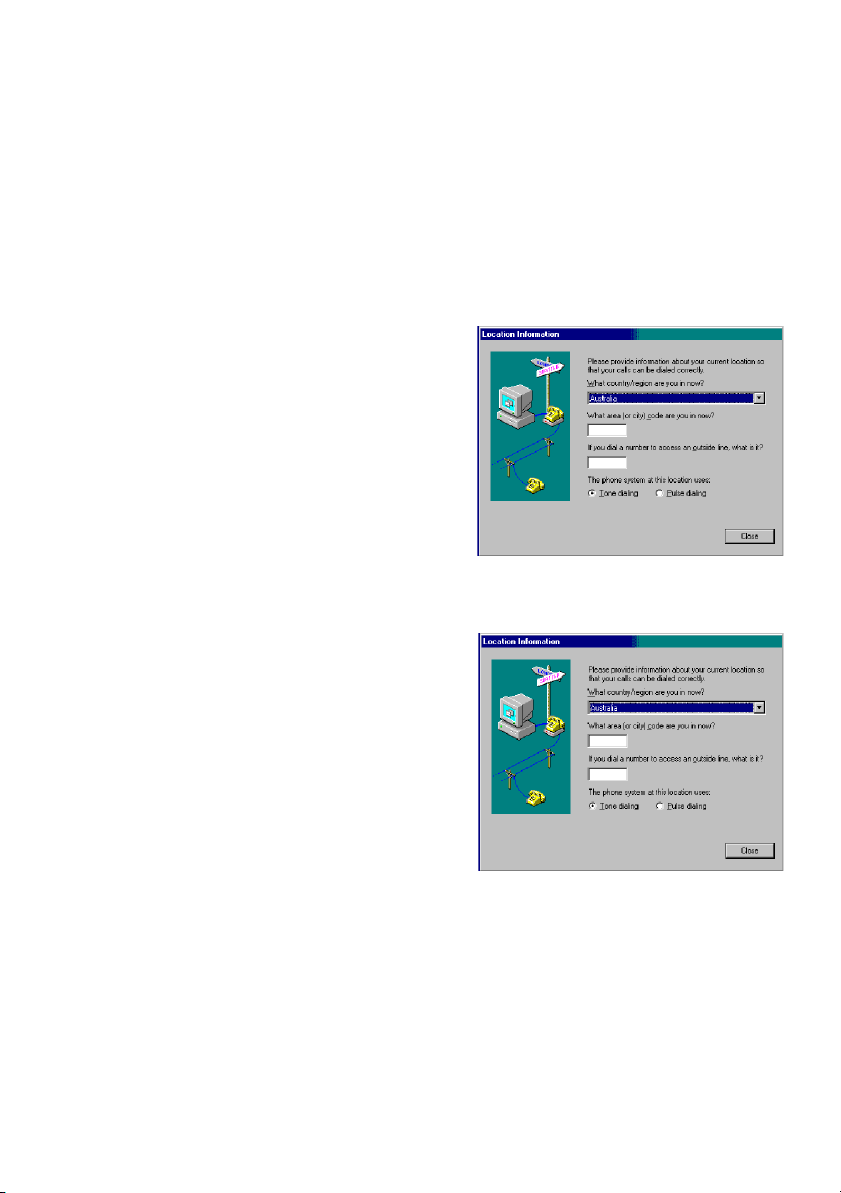
Note: Modem setting in Windows 98 / Windows Me
The default modem setting in Windows 98 / Windows Me operating system is United States of
America. If you are residing in Australia or New Zealand, please choose the appropriate country
where you are located.
The Modem will only operate with Tone Dialing; Selection of Pulse dialing is not possible.
Please see below instruction for quick modem setup.
A. If you are located in Australia
1. Go to Control panel, select modem icon.
2. Choose Australia in “What country/region
are you in now?”
3. Select Phone system as “Tone Dialing”
4. Close
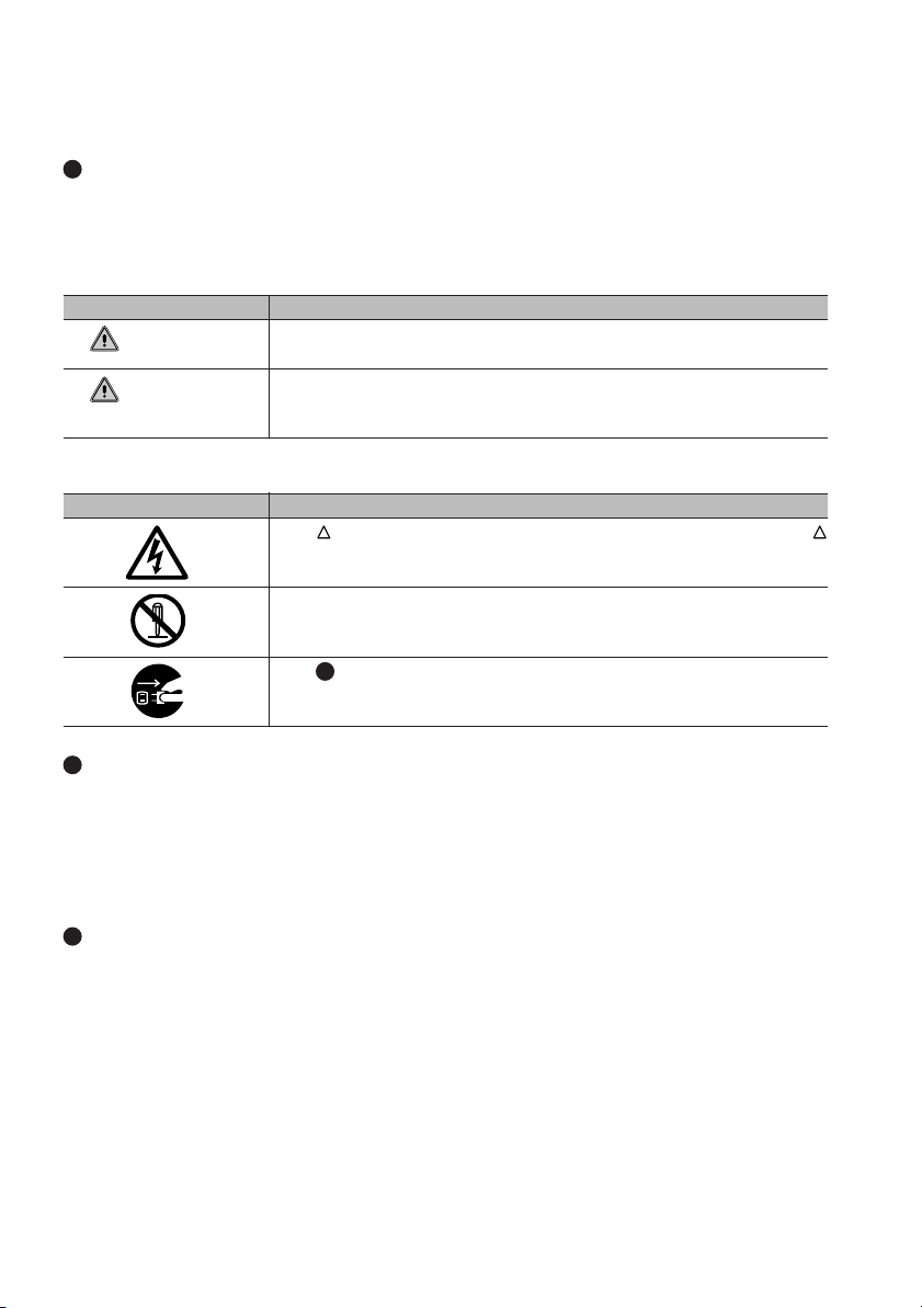
B. If you are located in New Zealand
1. Go to Control panel, select modem icon.
2. Choose New Zealand in “What country/
region are you in now?”
3. Select Phone system as “Tone Dialing”
4. Close
Page 6
NOTATION IN THIS DOCUMENT
Warnings
This manual uses a variety of icons as visual marks so that you can use this computer safely and
correctly and avoid damage and danger to yourself and to others. These icons and their meanings
are as follows. Please learn these icons before reading this manual. Learning these icons will be
useful for understanding this manual.
Icon Meaning
WARNING
CAUTION
The symbols below are used together with the icons above to indicate what type of danger or
damage is involved.
Symbol Meaning
Incorrect handling or ignoring this warning can cause a dangerous
situation that could result in death or severe injury.
Incorrect handling or ignoring this warning can cause a dangerous
situation that could result in moderate or minor injury or could result in
equipment damage.
The symbol indicates a warning or caution. The symbol inside the
indicates the concrete nature of the warning. (The example on the left
is a caution for electric shock.)
The circle and slash indicates prohibited behavior. The symbol inside
the circle indicates the concrete nature of the prohibition. (The
example on the left indicates that disassembly is prohibited.)
The indicates instructions that must be followed. The symbol inside
indicates the concrete nature of those instructions. (The example on
the left tells you to unplug the power plug from the socket.)
Key notation and operation methods
Explanations of key operations do not show all the characters on the keyboard. Instead they
indicate just the keys necessary to the explanation as follows.
Examples: [Ctrl] key, [Enter] key, [ → ] key
When multiple keys are to be pressed at the same time, this is indicated by connecting them with
[+].
Examples: [Ctrl] + [F3] keys; [Shift] + [ ↑ ] key
Screen examples
The screens shown in this manual are examples. Please understand that the file names and
screens you use may be different.
Page 7

Notation in text
Here is what symbols in text mean.
Symbol Meaning
Critical Points
Indicates a point necessary for correctly operating the hardware or
software.
Gives the meaning and brief explaination of a term.
Column
→ Indicates the page to see elsewhere in this manual.
Command input (key input)
Within the text of this manual, command input (giving commands to the computer by pressing
keys) is indicated as follows.
Example:
In the position indicated in the example above by the ↑, the space left between the characters
indicates that a space needs to be left in the entry by pressing the space bar (the long key with
nothing written on it at the center of the front of the keyboard). Commands are written in this
manual as lowercase latin letters, but uppercase letters may be used.
Product names
The following product names are abbreviated as follows in this manual.
“Microsoft® Windows® 98 operating system” is written as “Windows 98”.
“Microsoftt® Millennium® Edition operating system” is written as “Windows Me”
“Microsoft® MS-DOS® operating system Version 6.2/V” is written as “MS-DOS”.
“Microsoft® Windows® operating system Version 3.1” is written as “Windows 3.1”.
“Microsoft® Windows NT® Server network operating system Version 3.5” and “Microsoft® Windows
NT® Workstation operating system Version 3.5” are both written as “Windows NT 3.5”.
“Microsoft® Windows NT® Server network operating system Version 3.51” and “Microsoft® Windows
NT® Workstation and NT Server Version 4.0” are both written as “Windows NT 4.0”.
“Windows NT 3.51” and “Windows NT 4.0” are both written as Windows NT.
“Fujitsu Lifebook” is written as “this computer” or “the computer main unit”.
dir c:
↑
Page 8

Configuration of this Manual
SECTION 1
This section explains basic operations and basic items for using this computer, including the
names of the parts and their functions, Flat point operation methods, floppy disk unit handling,
and battery operation.
SECTION 2
This section explains installation of options for this computer.
SECTION 3
This section explains what to do when trouble occurs with this computer and when messages are
displayed. Read this section as the necessity arises.
SECTION 1
SECTION 2
SECTION 3
Page 9

CONTENTS
SECTION 1
1. Names of the Parts and their Functions .............................2
2. Keyboard ..............................................................................10
3. Flat Point ..............................................................................13
4. CoolScroll Button ................................................................16
5. CoolView Panel/One-touch Buttons ..................................19
Front .................................................................................................... 2
Left Panel ............................................................................................ 4
Right Panel ..........................................................................................5
Rear Panel........................................................................................... 7
Bottom ................................................................................................. 9
Names and Functions of the Principal Keys...................................... 10
About the Ten-key Mode ....................................................................12
About the Flat Point ........................................................................... 13
How to use the Flat Point .................................................................. 14
About the CoolScroll Button .............................................................. 16
About the CoolScroll Button .............................................................. 16
Using the CoolScroll Button Feature ................................................. 16
Using the CoolScroll Menu ................................................................ 17
Starting an application ....................................................................... 22
Switching modes ............................................................................... 22
Operating a music CD ....................................................................... 23
6. LifeBook Application Panel ................................................24
Application Launcher Buttons Disc Player Buttons ........................... 24
E-Mail Notification LED ..................................................................... 25
Configuring your Lifebook Application Panel ..................................... 25
Configure your E-mail Account Settings ............................................ 28
Using the CoolView Applet ................................................................ 33
Using the Disc Player ........................................................................ 36
Desktop Control Panel....................................................................... 37
7. Power Saving Function .......................................................39
Standby and hibernation ................................................................... 39
Standby ............................................................................................. 41
Hibernation ........................................................................................ 44
8. Battery ..................................................................................47
Charging ............................................................................................ 47
Using the Computer with the Battery ................................................. 47
Checking the Remaining Battery Power ............................................ 48
Notes on Battery ................................................................................ 50
Replacing the internal battery pack ................................................... 51
Page 10

SECTION 2
9. Floppy Disk ..........................................................................52
Caution in Using a Floppy Disk ......................................................... 52
Floppy Disks that can be Used with your Computer.......................... 52
Inserting a Floppy Disk ...................................................................... 53
Ejecting a Floppy Disk ....................................................................... 53
Protecting Data on a Floppy Disk ...................................................... 54
10. CD/DVD................................................................................. 55
Caution in Handling a CD/DVD ......................................................... 55
Caution in writing or rewriting data on a CD-R/RW ........................... 56
Loading a disc ................................................................................... 57
Ejecting the disc ................................................................................ 59
11. Internal Modem ....................................................................62
Connecting a modular cable .............................................................. 62
Caution in using the Internal Modem ................................................. 64
1. PC Card ................................................................................ 66
Caution in Using PC Cards ............................................................... 66
PC Cards that can be Used with your Computer .............................. 67
Preparing Necessary Items ............................................................... 67
Installing a PC Card .......................................................................... 67
Ejecting a PC Card ............................................................................ 68
2. LAN .......................................................................................71
Preparing Necessary Items ............................................................... 71
Connecting a LAN Cable ................................................................... 71
3. Expanding Memory .............................................................73
Preparing Necessary Items ............................................................... 73
Installing memory .............................................................................. 73
4. Before Connecting Peripherals ..........................................80
5. Connecting a USB Device .................................................. 81
Preparing Necessary Items ............................................................... 81
Connecting a USB Device ................................................................. 81
6. Connecting a TV .................................................................. 82
Preparing Necessary Items ............................................................... 82
Connecting a TV ................................................................................ 82
Page 11

7. Connecting a Printer ...........................................................84
Preparing Necessary Items ............................................................... 84
Connecting a Printer .......................................................................... 84
Caution in Using a Printer ................................................................. 85
8. Connecting a Mouse ...........................................................86
Connecting a PS/2 mouse ................................................................. 86
Connecting a USB mouse ................................................................. 87
Disabling the Flat Point...................................................................... 87
9. Connecting an External Display......................................... 89
Preparing Necessary Items ............................................................... 89
Connecting an External Display ........................................................ 89
10. Scanning Frequencies of the External Display ................ 91
External Display ................................................................................ 91
Simultaneous Display ........................................................................ 91
11. Bluetooth™ Quick Guide (only for selected model) ........ 92
Preparation for quick connections ..................................................... 97
Starting Quick Connection Tool ....................................................... 101
General outlines of services ............................................................ 101
LAN connections ............................................................................. 102
File transfer...................................................................................... 104
Dial-up connections ......................................................................... 107
Fax connections .............................................................................. 109
i-Point connection ............................................................................ 112
Simultaneous connections .............................................................. 115
Breaking off a quick connection ...................................................... 117
Quick Connection Settings dialog box ............................................. 117
Changing settings ............................................................................ 119
General outlines of the file transfer function .................................... 122
Installing Bluetooth™ Link ............................................................... 122
Starting/exiting Bluetooth™ Link ..................................................... 123
Settings ........................................................................................... 124
Selecting shared folders .................................................................. 124
Preparation for working with files..................................................... 128
Working with files ............................................................................ 128
Q & A for troubleshooting ................................................................ 130
SECTION 3
1. When This Happens .......................................................... 132
2. Maintenance of your Computer........................................ 136
3. Glossary .............................................................................141
Index
Page 12

SECTIONSECTION
SECTION
SECTIONSECTION
SECTIONSECTION
SECTION
SECTIONSECTION
11
1
11
11
1
11
This section explains basic
operations and basic items for
using this computer, including
the names of the parts and their
functions, Flat point operation
methods, floppy disk unit
handling, and battery operation.
SECTION 1
Page 13
SECTION 1
1.
Names of the Parts and their Functions
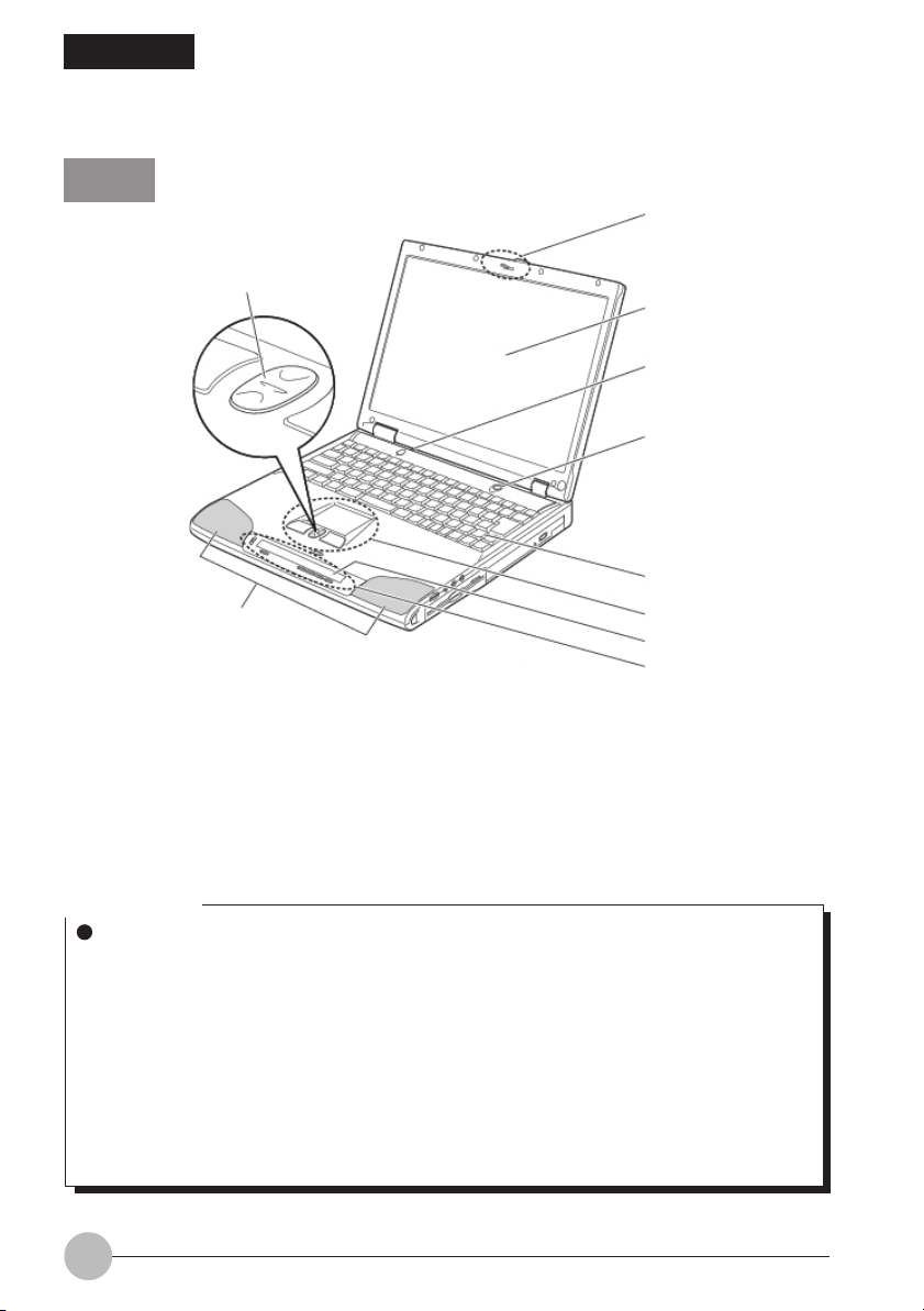
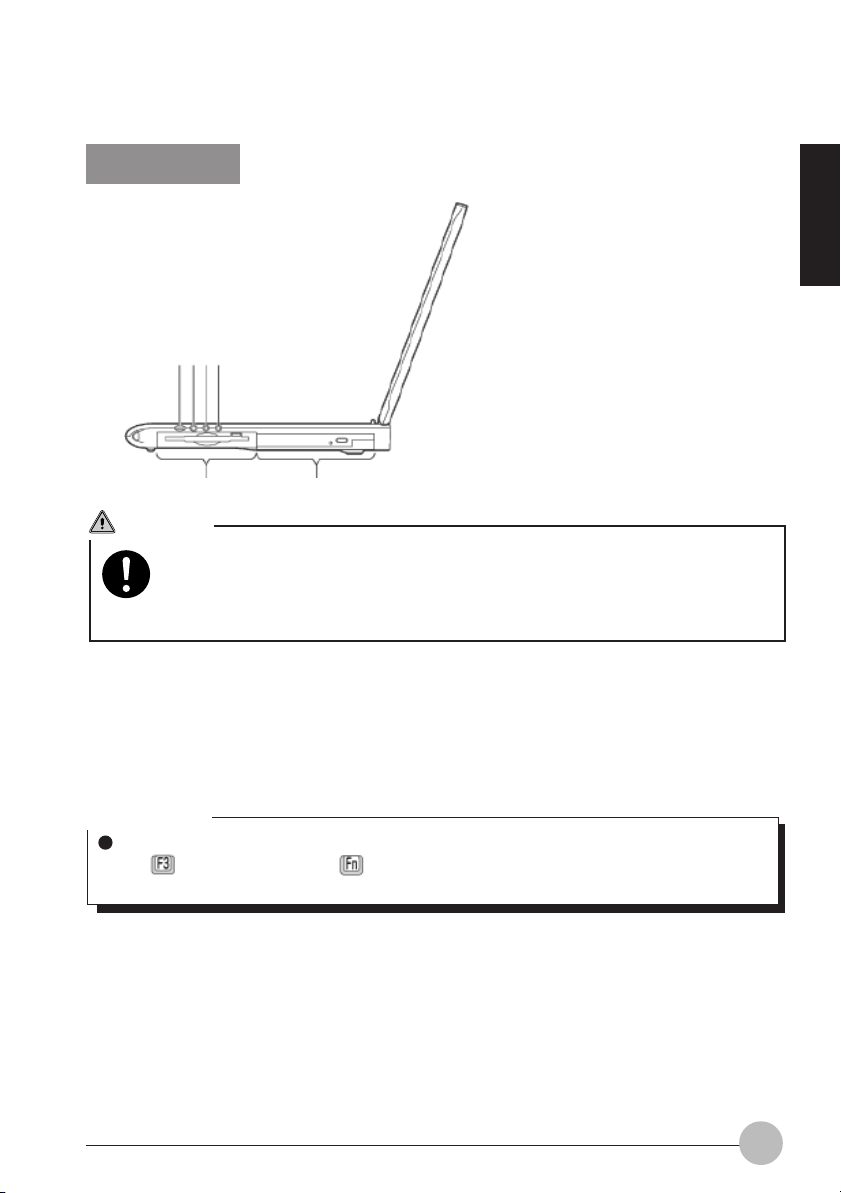
Front
1
10
2
3
4
5
9
(The illustration varies depending on the model and use conditions.)
6
7
8
1. Latch
Used to lock the LCD display to prevent it from opening accidentally.
To open the LCD display, release it by sliding the tab to the right.
2. LCD display
The monitor of your computer
Critical Point
About the characteristics of LCD displays
For reasons of characteristics specific to LCD displays, the following phenomena may occur
but they are not defects in your LCD display.
- The TFT color liquid crystal display (LCD) of your computer consists of more than
4,410,000 pixels (dots) (if the resolution is 1400x1050) or 2,350,000 pixels (if the
resolution is 1024x768), which are arranged in rows and columns through the utilization
of high-level technology. For technical reasons, however, some dots on your LCD display
may not light up or be always lit, but this does not mean that the display is defective.
- There may be a slight difference in color between your LCD display and another LCD
display because of differences in manufacturing condition. Moreover, your LCD display
may produce colors somewhat unevenly because of temperature changes, etc.
2
Page 14

3. Cover close switch
When you open or close the LCD display, this switch automatically puts the computer into standby
(suspending operation) mode, resumes system operation, or turns off the backlight of the LCD
display.
4. SUS/RES (Suspend/Resume) switch
Used to turn on your computer, to put it into standby (suspending operation) mode, or to resume
system operation.
5. Keyboard
Allows you to type in letters and figures and to give instructions to the computer.
6. Flat Point
Used to control the mouse pointer.
7. CoolView Panel
Displays the operating status of the CoolView function.
8. One-touch buttons
Used to start applications and to play music CDs.
9. Speakers
A sound output device of the computer
10. CoolScroll button
Used to scroll up and down the active window. By pressing the center, you can start an application
or operate Internet Explorer.
Critical Point
For some applications, you cannot use the CoolScroll button to scroll up and down windows.
SECTION 1
3
Page 15
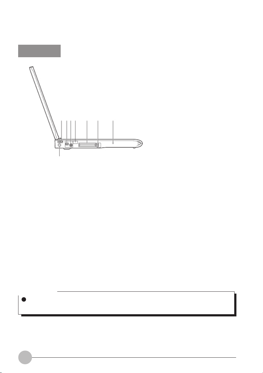
Left Panel
123 4 5 6 7
8
1. MAIN switch
The power switch of the computer
2. IEEE 1394 (DV) port
Used to connect a peripheral device, e.g., a digital video camera (DV), to the computer via a DV
cable.
3. S-video port
Outputs S-video signals.
4. Infrared Communication Port
This port enables you to make infrared communication.
5. PC card slot
Used to install optional PC cards. The lower and upper slots are referred to as Slot 1 and Slot 2,
respectively.
6. PC card eject button
Used to eject the PC card.
7. Antitheft lock port
Used to connect a commercially available antitheft cable.
Critical Point
The antitheft lock port supports the Kensington’s Micro Saver Security System.
Trade name: Micro Saver (Security Wire)
8. DC-IN jack
Used to connect the supplied AC adapter.
4
Page 16
Right Panel
1 2 3 4
56
CAUTION
HEARING LOSS
Turn down the volume to a minimum before connecting a device to the headphone
jack, Line-In jack or microphone jack. Failure to do so could cause damage to the
device connected or result in hearing loss because of very loud sound produced.
1. Volume control
Used to adjust the volume up or down. Turn it counterclockwise to lower the volume, or turn it
clockwise to raise the volume. You can also use the Volume Control dialog box to adjust the
volume and sound balance. If you cannot obtain an enough volume even if you turn up the
volume to a maximum, then use the Volume Control dialog box to make system sounds louder.
SECTION 1
Critical Point
If no sound comes out from the speakers even if you adjust the volume, press and hold down
the key while holding the key down until you hear a beep. Also, check to see that
[Mute] is not selected in the Volume Control dialog box.
2. Headphone jack
Used to connect commercially available headphones (with a 3.5-mm mini plug). Headphones
with some types of plugs cannot be connected. So before purchasing headphones, make sure
they are compatible with your computer.
5
Page 17

CAUTION
HEARING LOSS
Don’t raise the volume too high especially when you are listening with headphones.
Listening to very loud sound for a long time could impair your hearing.
HEARING LOSS
Don’t turn on or off the computer while you are wearing headphones, or noise could
impair your hearing.
3. Line-In jack/Optical digital audio output terminal
This is an analog input terminal used to connect the computer to the Line-Out terminal of an AV
system (with a 3.5-mm mini plug). This terminal can also be used as an optical digital output
terminal to connect the computer to the optical digital input terminal of an MD player, etc. (with a
3.5-mm fiber-optic mini plug).
4. Mic-In jack
Used to connect a commercially available monaural microphone (with a 3.5-mm mini plug) for
sound recording.
Some types of microphones (e.g., dynamic microphones) cannot be used with your computer.
So before purchasing a microphone, make sure it is compatible with your computer.
5. Floppy disk drive
Reads and writes information on floppy disks.
6. CD/DVD drive
Reads information on CD-ROMs and plays music CDs.
This drive is also capable of writing or rewriting data on CD-R/CD-RW, playing DVD-VIDEOs,
and reading information on DVD-ROMs.
6
Page 18
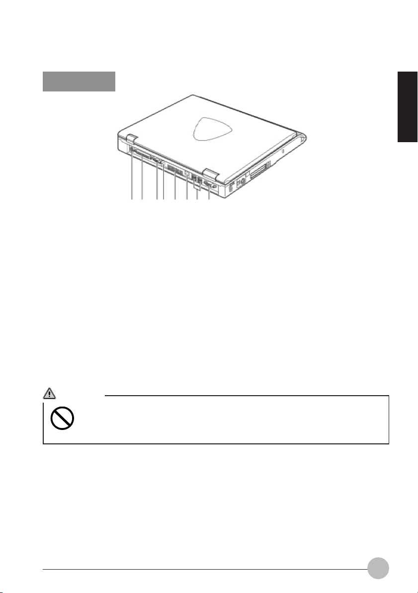
Rear Panel
12 34 5 6 7 8
(The illustration varies depending on the model and use conditions.)
1. Expanded keyboard/mouse port
Used to connect an optional ten-key pad or mouse.
2. Parallel port
Used to connect an optional printer, etc.
3. Serial connector
Used to connect an RS-232C standard-compliant device.
4. Modular jack
Used to connect the computer to a telephone line via the supplied modular cable to browse the
Internet, or send and receive e-mail across the Internet.
5. Cooling fan
Discharges heat from the computer. The cooling fan automatically starts running when the
temperature inside the computer rises to a specified temperature.
SECTION 1
CAUTION
FAILURE
Don’t block the vent for the cooling fan, or heat will remain in the computer and may
cause it to malfunction.
7
Page 19

6. LAN port
Used to connect the computer to a local-area network (LAN) via an optional fiber-optic LAN
cable to browse the Internet, or send and receive e-mail across the Internet.
7. USB port
Used to connect a USB-compliant peripheral device. Three USB ports are provided for this model.
8. External display port
Used to connect an optional external display, e.g., CRT display.
IMPORTANT
• When connecting a peripheral to each port, check the orientation of the connector and insert it
straight.
8
Page 20
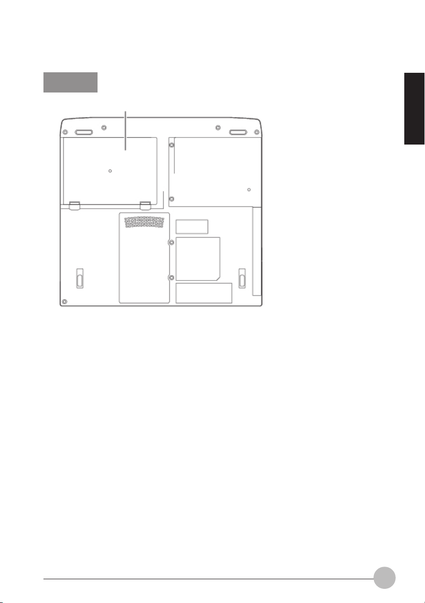
Bottom
1
1. Internal battery pack
An internal battery pack is installed here.
SECTION 1
9
Page 21
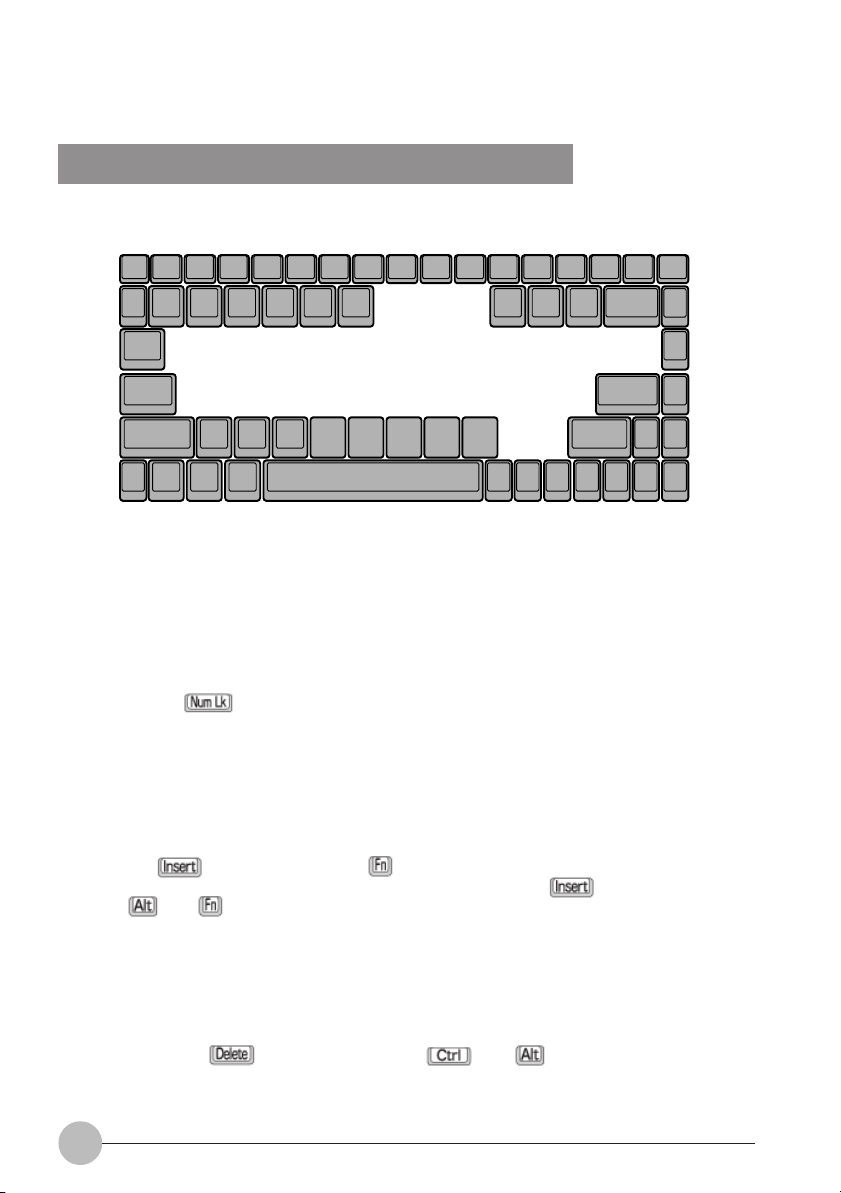
2. Keyboard
Names and Functions of the Principal Keys
1. Esc (Escape) key
Used to cancel the current task and return to the previous task.
2. Function keys
Functions assigned to these keys vary from application to application.
3. Num Lk (Numerical Lock) key
Pressing the key activates the ten-key mode. To deactivate the ten-key mode, press it
once again.
4. Insert / Prt Sc (Print Screen) key
• Insert key
Used to specify whether to overwrite an existing string or to insert a new string.
• Prt Sc (Print Screen) key
Used to save the currently displayed windows as pictorial data (bitmap file). To do so, press
the key while holding the key down.
To save only the active window as pictorial data, press the key while holding the
and keys down.
Using painting software (e.g., Paint), you can edit, save, and print pictorial data. To do so,
you need to import it to the painting software by selecting the Paste command from the Edit
menu.
5. Delete key
Used to delete the character on the right of the cursor. With this key, you can also delete the file
or icon you selected.
By pressing the key while holding the and keys down, you can forcibly
terminate the out-of-control application or computer.
10
Page 22

6. Back Space key
Used to delete the character on the left of the cursor.
7. Home key
Press this key to move the cursor directly to the first page of the document or to the head of the
row.
8. Pg Up and Pg Dn (Page Up and Page Down) key
Used to display the next page. To do so, press the Pg Up or Pg Dn key.
9. Enter key
Used to confirm the string entered.
In text processing, pressing this key inserts a hard return in the text. That’s why this key is also
called the Return key.
10. End key
Press this key to move the cursor directly to the end of the row or end of the document.
11. Cursor keys
Used to move the cursor upward, downward, to right and left.
12. Application key
Used to open the pop-up menu for the item selected.
This key has the same function as the right button of the Flat Point.
13. Alt key
Used in combination with other keys.
14. Windows key
Used to open the Start menu.
15. Ctrl key
Used in combination with other keys.
16. Fn key
This key, specific to your computer, is used in combination with other function keys, as described
below.
SECTION 1
+ Turns on or off the sound output (internal speaker and headphones).
+ Enables or disables the Flat Point when the Manual option is selected under “Internal
pointing device” of the BIOS Setup window.
+ Switches between Full-Screen mode and Normal Display mode (display in the center
of the screen) when the resolution is set to a lower value than the default value.
+ Dims the LCD display.
+ Brightens the LCD display.
+ When an external display is connected, this combination of keys can be used to
switch between the LCD display and the external display.
+ When a TV is connected, this combination of keys can be used to switch the display
on TV on and off.
11
Page 23

17. Shift key
Used in combination with other keys. By pressing a key while holding the key down, you
can enter the character or symbol printed in the upper case of the key.
18. Caps Lock key
To fix to the English Capital mode, press the key. To deactivate the Capital mode,
press this key again.
About the Ten-key Mode
The ten-key mode refers to the mode that enables you to use certain character entry keys as
ten-keys (a key arrangement that makes it easy to type in figures). To activate the ten-key
mode, simply press the key. In the ten-key mode, is displayed on the CoolView
Panel. The figure you can enter with a ten-key is marked on the front surface of the key. If you
connect an optional ten-key pad to your computer, the ten-key feature of your computer
becomes disabled.
12
Page 24
SECTION 1
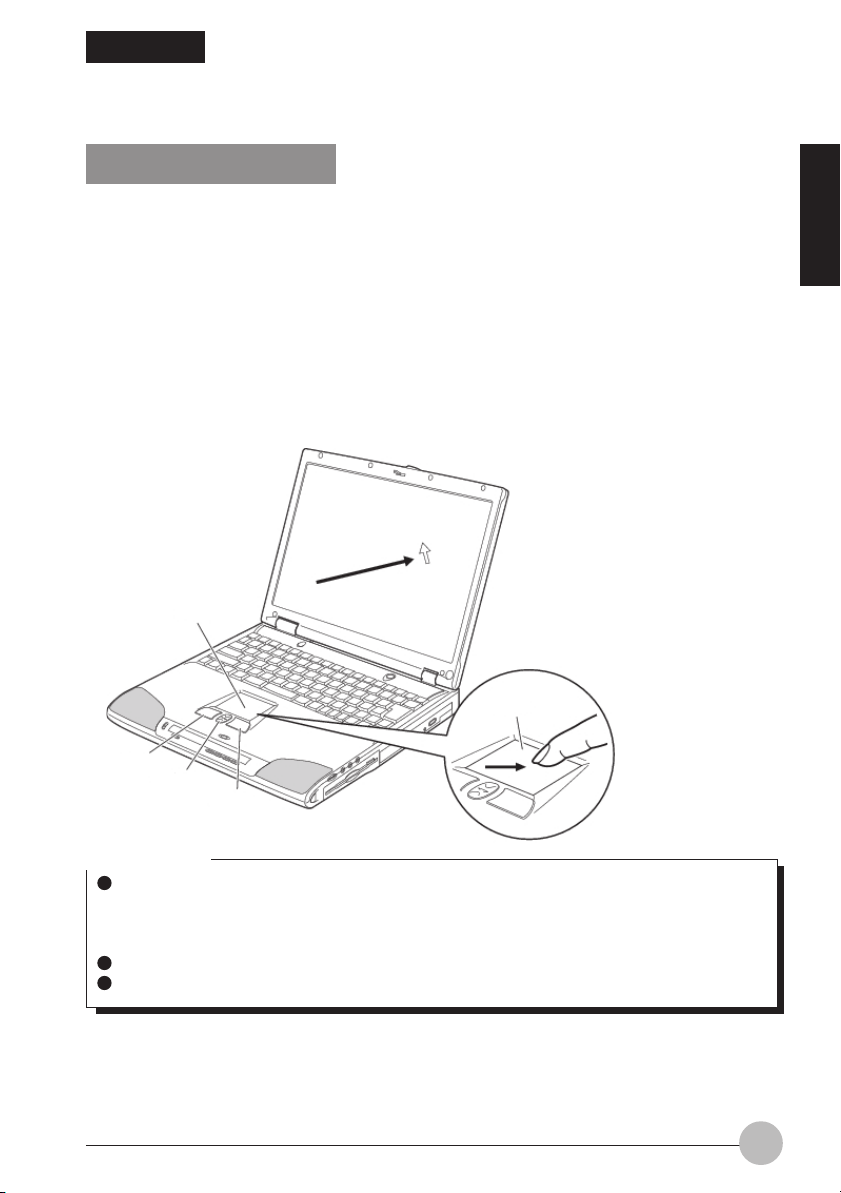
3. Flat Point
About the Flat Point
The Flat Point is a handy pointing device that enables you to move the mouse pointer freely with your
finger. It consists of a touch-pad, two buttons on this side of the touch-pad, and the CoolScroll between
the buttons.
The touch-pad has the same function as the ball in a mouse. You can move the mouse pointer in any
directions on the screen by sliding the tip of a finger on the touch-pad. Moreover, if you tap the touchpad with a finger, you can click, double-click, point to, or drag any object on the screen.
The buttons on both sides of the CoolScroll correspond to the left and right buttons of a mouse, and
their functions vary from application to application.
Pressing the CoolScroll forward or backward enables you to easily scroll a window up or down. By
pressing the center of the CoolScroll, you can also start applications or operate Internet Explorer.
Touch-pad
SECTION 1
Touch-pad
Left button
CoolScroll
Right button
Critical Point
The Flat Point may malfunction if condensation occurs or if it is moistened. In addition, if you
operate it with a moistened or sweaty finger, or if the Flat Point surface is dirty, the mouse
pointer may not move correctly. In such a case, turn off your computer and wipe dirt off with
a soft cloth slightly dampened with dilute detergent.
Some applications do not allow you to use the CoolScroll to scroll windows.
You can use an optionally available mouse instead of the Flat Point.
13
Page 25
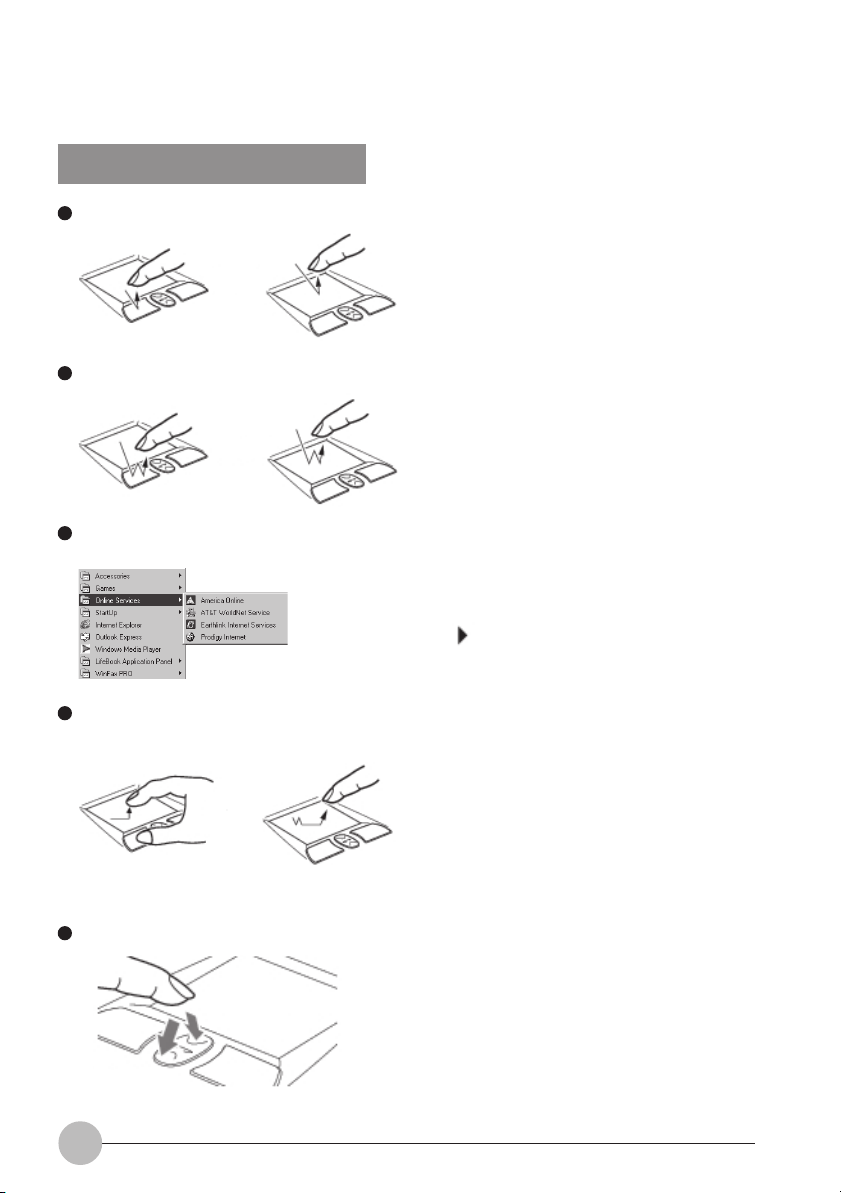
How to use the Flat Point
Click
Double-click
Point
Drag
“Click” means quickly pressing the left button once
or tapping the touch-pad once.
Pressing the right button once is called “right-
or
or
or
click.”
“Double-click” means pressing the left button
twice in a row or tapping the touch-pad twice in a
row.
“Point to an item” means moving the mouse
pointer onto a menu item, and so on, to select it.
Pointing to an item highlights it and displays an
explanation about it. If the item to which you
pointed has a submenu (such items are marked
with ), the submenu appears.
To drag an object, move the mouse pointer onto
the object, move the object to the desired location
by sliding the finger on the touch-pad while
holding the left button down, and then move the
finger off the pad. Or, move the mouse pointer
onto the object, and tap the touch-pad twice in a
row. After that, without moving the finger off the
pad, slide it to move the object to the desired
location, and then move the finger off the pad.
14
Scroll
To return, push this forward.
To advance, push this backward.
To scroll a window, click anywhere in the window
and push the CoolScroll forward or backward to
scroll the window.
Page 26

Critical Point
Using the Mouse Properties dialog box that opens when you click the (Mouse) icon in
the Control Panel window, you can change the functions of the left and right buttons and the
mouse pointer speed.
When tapping the touch-pad, tap it quickly with the tip of a finger but not strongly.
The mouse pointer moves in the same direction as you slide a finger on the touch-pad. If the
finger reaches one edge of the pad before you move the pointer to the desired location,
move the finger off the pad temporarily, put it in an adequate place on the pad and start
sliding the finger again.
SECTION 1
15
Page 27
SECTION 1
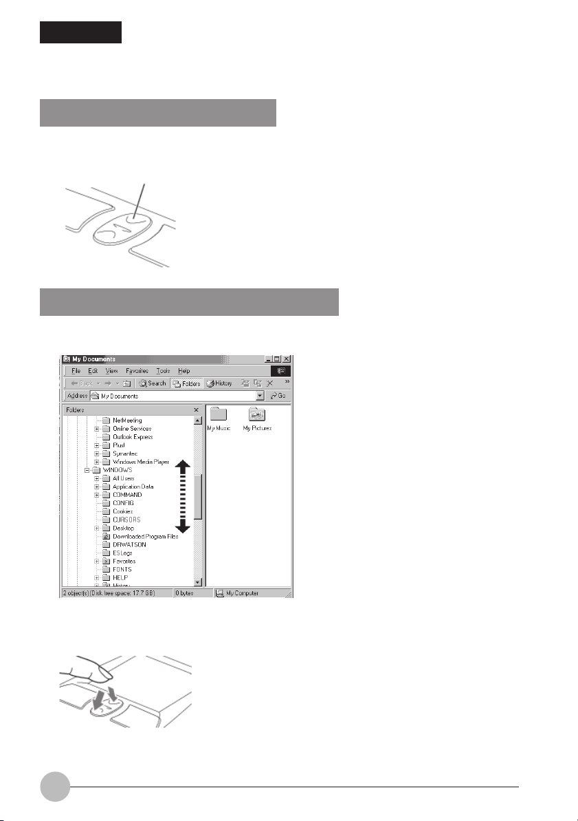
4. CoolScroll Button
About the CoolScroll Button
The CoolScroll button enables you to easily scroll a window up or down. With the CoolScroll
button, you can also start applications or operate Internet Explorer.
CoolScroll button
Using the CoolScroll Button Feature
1. Click on the Windows Explorer you want to scroll.
2. Press the CoolScroll button forward or backward.
The active window starts scrolling up or down.
To advance, push this backward.
To return,
push this forward.
16
Page 28
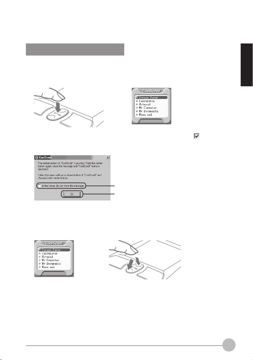
Using the CoolScroll Menu
Pressing the center of the CoolScroll button displays the CoolScroll button menu that enables
you to start applications.
1. Press the center of the CoolScroll button.
2. Click the “In future, do not show this message.” option (1) to check it , then click OK
(2).
You need to select this option only when you use the CoolScroll for the first time.
(1)
(2)
3. Press the CoolScroll button forward or backward to select the application you want to
open.
The default application are Screen Saver, Calculator, NotePad, My Computer, My Documents
and Menu end.
SECTION 1
To scroll up, push this forward.
To scroll down,
push this backward.
4. Press the center of the CoolScroll button.
The menu will disappears once you have selected the application and the application will starts.
17
Page 29
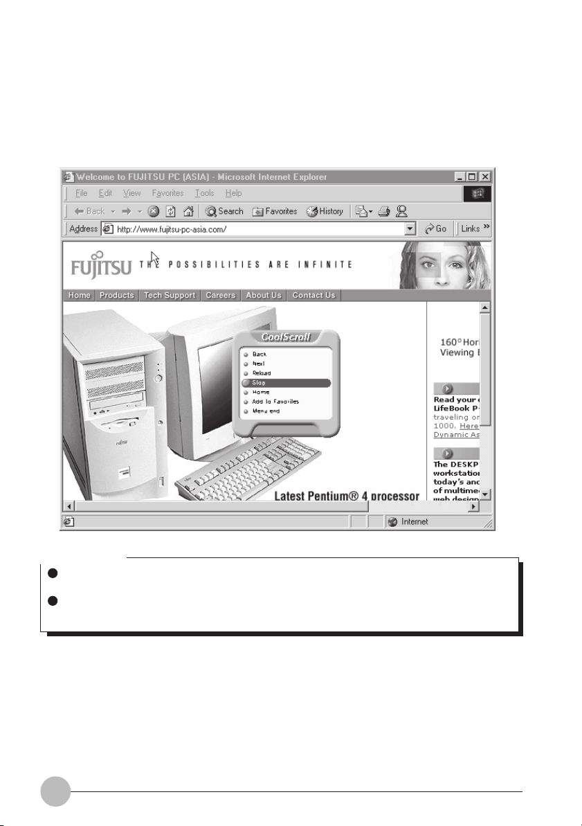
5. CoolScroll menu will appears different application when activate in Internet Explorer.
The CoolScroll menu will appears different programs when you press CoolScroll button while the
Internet Explorer is active. It contains Back, Next, Reload, Stop, Home, Add to Favorites and
Menu end. You can select this features for browsing.
Critical Point
If another window is activated while the CoolScroll menu is open, the window may scroll up
or down as you move from one option to another in the menu, using the CoolScroll button.
If you press the center of the CoolScroll when Internet Explorer is active, the Internet
Explorer menu appears.
18
Page 30
SECTION 1
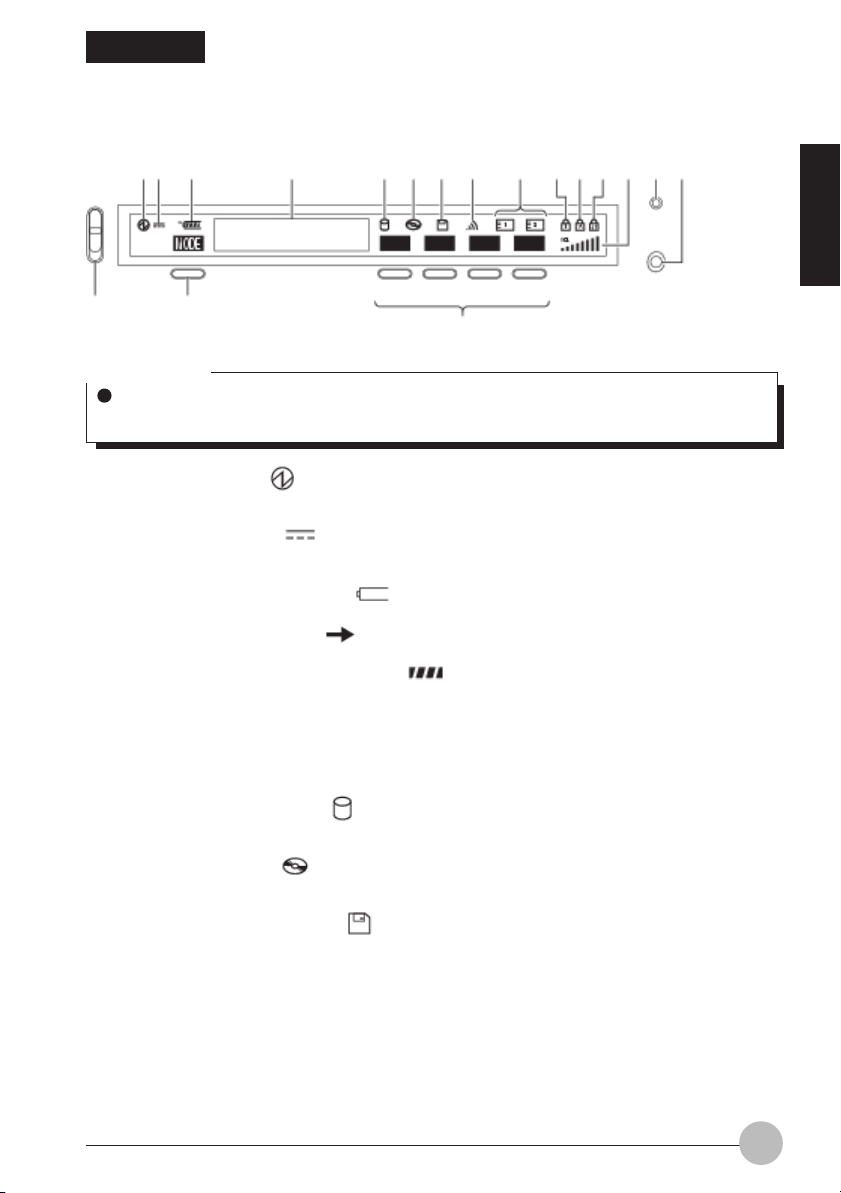
5. CoolView Panel/One-touch Buttons
12 3 4 5 6 7 8 9 101112 13 1718
SECTION 1
14
15
16
Critical Point
When the MAIN switch is off, nothing is displayed on the CoolView Panel except when the
computer is being recharged.
1. SUS/RES indicator ( )
This indicator comes on when the computer is running and blinks in standby status.
2. AC Adapter indicator ( )
This indicator comes on when the power is supplied from an AC adapter.
3. • Battery Installation indicator ( )
This indicator appears when a battery is installed.
• Battery Charge indicator ( )
This indicator appears when the battery is charged.
• Remaining Battery Power indicator ( )
This indicator indicates the remaining battery power.
4. Message display area
Displays various messages according to the situation, e.g., when the computer is in the process
of starting or it receives e-mail.
5. Hard Disk Access indicator ( )
This indicator appears when the internal hard disk is accessed.
6. CD Access indicator ( )
This indicator appears when a CD is accessed.
7. Floppy Disk Access indicator ( )
This indicator appears when a floppy disk is accessed.
8. Bluetooth(TM) status indicator (For model with Bluetooth(TM) intergrated)
Lit when the computer is ready for communication with other Bluetooth(TM) devices.
19
Page 31

9. PC Card Access indicator ( , )
This indicator appears when a PC card is accessed.
10. Num Lock (Numerical Lock) indicator ( )
This indicator appears when the keyboard is set to ten-key mode. You can activate and deactivate
the ten-key mode by pressing the key.
11. Caps Lock indicator ( )
This indicator appears when the keyboard is set for all capital letters. You can activate or deactivate
the Caps Lock mode by pressing key.
12. Scroll Lock indicator ( )
This indicator appears when scroll lock is set to avoid screen scrolling. You can set and reset the
scroll lock by pressing the key while holding down the key.
It depends on the application when this indicator appears.
13. Sound Level indicator
Indicates the sound level you adjusted with the volume control.
Critical Point
The indicator shows the volume in 8 levels. Therefore, slightly adjusting the volume sometimes causes no change in the sound level displayed.
14. Lock switch
Slide this switch down to activate the mode button and one-touch buttons, or slide it up to deactivate
(lock) them.
15. Mode button
Used to switch the one-touch buttons from one mode to another. The one-touch buttons are
switched in the following sequence each time your press the Mode button: One-touch mode ->
Disc mode activate. One-touch mode -> Launcher button activate.
16. One-touch buttons
Allow you to quickly start applications, operate music CDs, or launching the applicaion, internet
or E-Mail. . The function of each button varies depending on the mode in which it is placed.
17. Bluetooth (TM) status indicator (For model with Bluetooth(TM) intergrated)
Lit when the Bluetooth (TM) device is in operation.
18. Bluetooth (TM) switch (For model with Bluetooth(TM) intergrated)
Used to turn on or off the Bluetooth (TM) device.
20
Page 32

Critical Point
If you turn off the MAIN switch or turn on or off the SUS/RES switch while the Hard Disk
Access indicator or Floppy Disk Access indicator is lit, data on the hard disk or the floppy
disk could be corrupted.
If the CD Auto-Insertion feature is activated, your computer checks periodically whether a
CD is loaded or not, and therefore the CD Access indicator on the CoolView Panel comes on
periodically. To deactivate the CD Auto-Insertion feature, follow these steps.
1. Click the Start button, and select Settings and Control Panel.
2. If the (System) icon is not found in the Control Panel window, click “View all Control
Panel options.”
3. Click the (System) icon.
4. Click the Device Manager tab.
5. Click the plus sign on the left of CD-ROM.
The CD-ROM device installed is displayed.
6. Click the CD-ROM device, and then click the Properties button.
The CD-ROM Device Properties dialog box appears.
7. Click the Settings tab.
8. Uncheck “Automatic notification of insertion” under Options.
9. Click OK.
10. Click the OK or Close button in the System Properties dialog box.
A message appears, asking whether you want to modify system settings.
11. Click Yes.
The computer shuts down and restarts.
To activate the CD Auto-Insertion feature again, check “Automatic notification of insertion”
in step 8.
SECTION 1
21
Page 33

Switching modes
The following three modes are provided for the one-touch buttons.
Modes Meaning
Launcher mode Allows you to start the application assigned to each button.
Disc mode Allows you to operate music CDs.
To switch modes, simply press the Mode button.
Mode button
Each time you press the mode button, the one-touch
buttons are switched from one mode to another, and
their functions displayed are switched accordingly, as
shown below.
Launcher mode
Disc mode
Starting an application
In One-touch mode, you can use the q;-touch buttons to start the following applications.
Buttons Applications that start
(1) A-button NotePad
(2) B-button Calculator
(3) Internet button *1*2 Internet Explorer (Web browser)
(4) E-main button *3 Outlook Express
*1: After you have subscribed to your Internet Service Provider.
*2: WEB or MAIL is displayed on the CoolView Panel.
*3: To use @ Mail, you need to set it up beforehand.
• You can change the applications assigned to each button.
22
Page 34

Operating a music CD
When the one-touch buttons are in the Disc mode, you can use them to operate music CDs.
Discs that can be used vary depending on each model.
Buttons
(1) (2) (3) (4)
Stop/Eject*1 Play/Pause Previous Track *1 Next Track *2
*1. By default, the Eject feature is set disabled while Windows is running.
*2. By pressing the Previous Track or Next Track button, you can skip to the previous or next title
respectively when playing a music CD.
When a music CD is being played, information about it is displayed on the CoolView.
Time elapsed since the start of
the current track or chapter
SECTION 1
Operating status
Even if Windows is terminated or on standby, you can play music CDs on your computer.
Inserting a music CD while Windows is running causes CD Player application to automatically start
and play the disc. To continue the operation, you can use one-touch buttons or CD Player.
Track or chapter number
IMPORTANT
• If you insert a music CD or DVD-VIDEO into the drive, CD Player or another DVD playing
application automatically starts and plays it. At that time, don’t start manually any application
that did not start automatically, for example, by selecting it from the Start menu. Doing so could
make system operations unstable.
• Don’t use the one-touch buttons to operate any types of CDs except music CDs. Doing so may
cause system operations unstable.
• Always power your computer from the AC adapter when playing a music CD or a DVD-VIDEO.
• When Windows is terminated or on standby, all volume control settings with Windows are
ineffective and the volume is set to the highest level. So turn down the volume before playing a
CD, and then turn it up to the desired level.
23
Page 35

SECTION 1
6. LifeBook Application Panel
One of the unique features of your LifeBook notebook is the LifeBook Application Panel. This panel
allows you to operate the Disc Player as an independent audio player (applies only to certain models)
or launch applications with the touch of a button even when your system is in suspend or pseudo-off
mode. (Pseudo-off mode applies only to certain models of LifeBook notebook. Pseudo-off is the
mode when Microsoft® Windows® has been shut down but the power switch on the notebook is still in
the ON position.)
On some LifeBook notebook models, the panel also allows you to secure your notebook from
unauthorized use. Your notebook is pre-installed with software utilities that you use to operate and
configure your LifeBook Application Panel. These utilities are found in two locations. The Disc Player
and the Software Instructions, are found by going to Start -> Programs -> LifeBook Application Panel.
For the Application Panel, go to Start -> Settings -> Control Panel. The LifeBook Application Panel
makes your LifeBook notebook more than just another notebook computer.
Critical Point
For the location of your LifeBook Application Panel please see your User’s Guide.
The Disc Player only works with audio CDs. The Disc Player or launch buttons will not work
when the power switch is in the Off position.
The panel consists of the following elements:
SELECTOR SWITCH (Select Models Only)
The selector switch allows you to select the function of the one-touch buttons by selecting from the
Mode button as an Application Launcher, a Disc Player (if available). The Disc Player is available only
on select models.
Left button
CoolScroll
Right button
Application Launcher Buttons Disc Player Buttons
When the Mode switch is set to Launcher, pressing any of the buttons will launch a user-defined
application. When the Mode switch is in the Disc Player position, the buttons operate the Disc Player,
and when the selector switch is in the Lock position, the buttons are disabled and do nothing when
pressed.
Critical Point
Certain models may have 4 or 5 buttons. Please refer to your User’s Guide for more details.
The Disc Player features are not available on all models.
If there is a CD in the player which has finished playing, the LCD will display a “1”, even
though it will not automatically start playing and will not automatically repeat the CD.
24
Page 36

E-Mail Notification LED
By setting up the E-mail LED notification in conjunction with your E-mail button setup, you can connect
to your ISP, check for and retrieve new mail, terminate connection, and activate the E-mail LED to
notify that new mail has arrived.
To use the E-mail LED notification, you must have access to a POP3 Server with no Security Password
Authentication. Contact your service provider to determine if they support POP3 without Security
Pass-word Authentication.
Critical Point
E-mail Notification LED is available on select LifeBook notebook models only.
Configuring your Lifebook Application Panel
When you start Windows, the LifeBook Application Panel is automatically activated.
As an application launcher, the LifeBook Application Panel is very flexible, giving you a variety of
options. To set up the Panel to best suit your needs, we have provided the Application Panel Setup
utility that quickly and easily helps you make the most of this valuable feature.
To configure your LifeBook Application Panel with Application Panel Setup:
1. Click on Start.
2. Click on Settings.
3. Click on Control Panel.
4. Click on Application Panel.
SECTION 1
25
Page 37

The Application Panel Setup utility will appear. There are tabs that correspond to the application
buttons on the LifeBook Application Panel. When you receive your notebook, these buttons are preconfigured to launch specific applications. For a list of the default applications associated with each
button, refer table below.
Label Button Function Default Application
1 Application A Notepad
2 Application B Calculator
3 Internet Internet Explorer
4 E-Mail Outlook Express
Critical Point
The tabs in Application Panel Setup may not be in the same order as the buttons on your
LifeBook notebook. Please carefully select the tab you wish to change.
To change an application associated with the Application A, Application B, or E-mail buttons, click on
the tab for the button you would like to reconfigure – for example, Application A. Click on Browse from
Start Menu, scroll down the list of applications, click on the application you wish to launch with this
button, and then click OK. The button will now launch the new application.
The Internet tab is different. It comes set to launch your default Windows Internet browser, (Internet
Explorer, unless changed.) In order to reconfigure it to launch another program follow these easy
steps:
1. Click on Other from the Internet browser box.
2. Click on Browse from Start Menu.
3. Scroll down the list of applications, and the click on the application you wish to launch
with this button.
4. Click OK.
26
Page 38

The button will now launch the new application. If you want to return to launching your Windows
default Internet browser with this button, you need only click on “Default Internet Browser” from the
Internet browser box. Be aware that you will erase the settings for the “other application”. If you wish
to go back to launching the “other application” from this button, you will need to reconfigure it as
described above.
When you have finished with Application Panel Setup click on OK, and the new settings will take
effect. You can reconfigure your LifeBook Application Panel as often as you like.
Critical Point
The Internet or E-mail buttons can be configured to launch any application you wish, not just
an Internet browser or e-mail program.
Enabling/disabling Application Launcher button (Select Models Only)
At the bottom of each application setup page are two selectable options. The first will “Keep this
button active even on Standby”, and the second will “Keep this button active even on Hard Drive
Timeout”. You can enable/disable either or both of these functions simply by check or unchecking the
check Box.
SECTION 1
Critical Point
If you choose to have the buttons work when the notebook is in standby or pseudo-off, they
will function even if hit accidentally. This will turn on your notebook even if you are not present
or using your notebook. This could deplete your battery, and you will need to recharge it
before using the notebook. As a precaution, move the selector switch, if available, to the
Lock position when you are away from your notebook.
27
Page 39

Configure your E-mail Account Settings
Critical Point
The E-mail Notification LED is available on select LifeBook notebook models only.
To use the E-mail LED notification, you must have access to a POP3 Server with no Security
Password Authentication. Contact your service provider to determine if they support POP3
without Security Password Authentication.
To configure the E-mail Account Settings:
1. Click on Start.
2. Click on Settings.
3. Click on Control Panel.
4. Click on Application Panel.
5. Click on the E-Mail tab.
6. Click on E-Mail Account Settings...
7. The E-Mail Setup screen appears. Choose the type of connection: LAN or Dial Up.
28
Page 40

• If LAN: Click on LAN. Enter the POP3 Server name, your account name and password for that
account. Consult your Service provider if you do not know or are unsure of the information
requested.
• If Dial Up: Click on Dial Up. Choose the Dial up configuration (as previously set in Dial Up
Networking) you wish to retrieve mail from. Enter the POP3 Server name, your account name
and password for that account. The account name and password should be the same information
you entered in the Dial Up configuration. After all the information has been entered, test the
connection by clicking on “Testing connection with current setting”. If an error occurs, check
the settings and information on Dial Up Network and E-mail LED notification.
After the setup (Dial Up Networking/E-mail/E-mail LED) is completed, you are ready to retrieve mail.
When you press the E-mail button, your system will establish connection with your provider, check for
and retrieve new mails, terminate the connection, and activate the blinking LED to alert you of new
mail.
To configure After checking mail
This setting let you set your computer to return back to the previous power saving state after checking
mail.
SECTION 1
29
Page 41

To configure Auto Mail Check
This function allow you to specify day and time for checking new mail. Only applicable when the PC
stays Standby.
To configure Mail Check Interval
This function allow you to specify an interval (minutes) for checking for a new mail during you use the
computer. Recommendation of this function use with LAN connection.
30
Page 42

To configure Important Mail
This function allow you to change the icon color on the taskbar to notifies you that an important mail
comes.
To configure Ring Pattern
This allow you to change the LifeBook Application icon’s color on the taskbar and beeps each time
you receive a new message.
32
Page 43

To confirue Message board
You can specify a message board that you want to show on the CoolView by type in your message on
the message box.You can click the preview button to view the message on the CoolView.
By default the CoolView only show the clock. If you want to show the message on the CoolView , you
have to right click the CoolView manager on the taskbar and select message board. It will show the
message you specify on the CoolView. Once you restart your system the message won't show on the
CoolView and you have to select from the CoolView manager.
To configure Setting
This menu allow you to configure the CoolView display. You can adjust the contrast of the CoolView
by adjusting the sliding bar from Light to Dark or vice-versa. For Backlight Color setting, you can
select either, No Backlight, Blue, Light blue, Ice blue, Green, Light green, Red or Pruple.
If you are in battery mode , we recommend you to set the Backlight color to No Backlight.
SECTION 1
35
Page 44

SECTION 1
7. Power Saving Function
Standby and hibernation
The Standby and Hibernation features allow you to save power without shutting down Windows.
Power consumption
Operation
Resume
Standby mode
This mode suspends system operation while keeping the programs and data in the system RAM
(memory). During standby, the icon on the CoolView Panel blinks. In this mode, the computer
can suspend and resume system operation in a shorter time than in hibernation mode. When the
computer is on standby, it consumes a small amount of power, and it is powered from the AC
adapter if the AC adapter is connected or from the internal battery if no AC adapter is connected.
Hibernation mode
This mode shuts down the computer after saving all programs and data in memory into the hard
disk. As compared to standby mode, it takes more time for the computer to suspend and resume
system operation because the power is turned off automatically. When the MAIN switch is on, the
computer consumes a small amount of power to keep the one-touch buttons operational. To stop
the power consumption, turn the MAIN switch off.
Standby
Hibernation
Large
Small
SECTION 1
39
Page 45

Closing the LCD display
1. Make sure that the or icon is not displayed on the CoolView Panel, then close the
LCD display.
After a while, the icon blinks on the CoolView Panel.
LCD display
CoolView Panel
Resume (Restoring suspended operation)
There are three ways to resume operation.
Using the SUS/RES switch
Use this method if you placed the computer into standby mode, using the Shut Down Windows dialog
box or the SUS/RES switch.
1. Make sure that the
42
Page 46

Opening the LCD display
Use this method if you placed the computer into standby mode by closing the LCD display.
1. Make sure that the icon is blinking on the CoolView Panel.
2. Open the LCD display.
Unlock the LCD display by sliding the latch on the front panel to the right, and lift the display while
holding the computer with a hand.
After a while, the system will resume at the same point as when you suspended operation.
Latch
Status indicator LCD
(The illustration varies depending on the model and use conditions.)
Resume by receiving an incoming call
Some communication applications allow the computer to automatically resume operation when the
internal model receives an incoming call. To make this possible, you need to keep the communication
program active during standby.
Caution about the standby mode
• Don’t turn the MAIN switch off during standby, or all data being processed will be lost.
• When the computer is powered from a fully-charged new battery, it can be kept on standby for
about 1 day.
• During standby, the computer consumes a small amount of power to keep data in the system
RAM. If power is supplied by the internal battery, pay attention to the remaining battery life. If the
battery goes dead during standby, all data being processed will be lost. If you know you will not
use the computer for a prolonged period of time, don’t put the computer into standby mode, but
save all data, shut down Windows and turn off the computer.
• When the computer resumes operation as a result of the reception of a incoming call, it will
display nothing on the screen. To turn on the display, touch the Flat Point (move the mouse). If
this does not turn on the display, press the @ key or any other key. If this operation does not still
restore the display, check whether the icon is blinking on the CoolView Panel. If it is blinking,
the computer is still on standby. In this case press the SUS/RES switch to resume operation.
• When power is supplied by the internal battery, the time for which your computer can be kept on
standby may be shortened, depending on the PC card installed.
• If you placed the computer into standby mode, using the Shut Down Windows dialog box or the
SUS/RES switch, opening the LCD display does not cause the computer to resume operation.
LCD display
SECTION 1
43
Page 47

Closing the LCD display
1. Make sure that the or icon is not displayed on the CoolView Panel, then close the
LCD display.
The icon is displayed on the CoolView Panel and the power is turned off after a while.
LCD display
CoolView Panel
(The illustration varies depending on the model and use conditions.)
Resume (Restoring suspended operation)
There are two ways to resume operation.
Using the SUS/RES switch
Use this method if you placed the computer into hibernation mode, using the Shut Down Windows
dialog box or the SUS/RES switch.
1. Simply press the SUS/RES switch.
A window appears on the screen, showing the progress of the reloading of the saved data from
the hard disk. After a while, the system will resume at the same point as when you suspended
operation.
SECTION 1
CoolView Panel
(The illustration varies depending on the model and use conditions.)
SUS/RES switch
Critical Point
If pressing the SUS/RES switch does not cause the computer to resume operation, it is
probable that the MAIN switch is turned off. If so, turn it on. This displays a window showing
the progress of the reloading of the saved data from the hard disk, and after a while, the
system will resume at the same point as when you suspended operation.
45
Page 48

Opening the LCD display
Use this method if you placed the computer into hibernation mode by closing the LCD display.
1. Open the LCD display.
Unlock the LCD display by sliding the latch on the front panel to the right and lift the display while
holding the computer with a hand.
A window appears on the screen, showing the progress of the reloading of the saved data from
the hard disk. After a while, the system will resume at the same point as when you suspended
operation.
Latch
CoolView Panel
(The illustration varies depending on the model and use conditions.)
LCD display
Critical Point
If opening the LCD display does not cause the computer to resume operation, it is probable
that the MAIN switch is turned off. If so, turn it on. This displays a window showing the
progress of the reloading of the saved data from the hard disk, and after a while, the system
will resume at the same point as when you suspended operation.
Caution about the hibernation mode
• Your computer cannot be put into hibernation mode unless the hard disk has enough free space
to store all data in memory.
• In hibernation mode, the reception of an incoming call will not cause the computer to resume
operation.
• If the computer is put into hibernation mode when peripheral devices, such as a PC card and a
printer, are connected to it, information about those devices will be initialized when you resume
system operation, and therefore the system may not resume at the point at which you suspended
operation.
• If you placed the computer into hibernation mode, using the Shut Down Windows dialog box or
the SUS/RES switch, opening the LCD display does not cause the computer to resume operation.
46
Page 49

Page 50

Battery malfunction indicator
This means that the battery is not charged properly.
Critical Point
When appears, turn off the power of the computer and reinstall the battery. If the
indication persists, the battery is defective. Replace it with a new battery.
If the battery is weak
When the battery is beginning to run down, the remaining battery power indicator ( )
on the CoolView Panel blinks. In such a case, connect the AC adapter to the computer
immediately to recharge it.
Critical Point
If you continue to operate the computer when the battery is low, the data you are entering or
in the process of saving may, at worst, be lost. Connect the AC adapter immediately or, if you
do not have one, quit the application you are running after saving the working data and then
shut down the power to the computer.
Reading and writing processes on the hard disk consumes a large amount of power. If you
save data on the hard disk when the battery is low, always connect the AC adapter.
If the computer is left in a low battery condition, it automatically goes into the standby mode.
If the system is reading/writing on the hard disk or other data storage media, however, it will
wait until the process is completed before entering the standby mode.
SECTION 1
IMPORTANT
• This computer is preset to enter the standby mode automatically when the remaining battery
level becomes 3%. Do not change the settings in the following items under [Critical Battery
Alarm] in the Alarm tab of the Power Management Property dialog box.
- [Issue alarm to notify low battery when the power level reaches the following point.]
- [Computer operation after the alarm is issued] in the dialog box [Alarm operation with low
battery] that will appear when you click [Alarm Operation]
• If you use your computer with these items unchecked , the power will be immediately shut
down when the battery becomes low and unsaved data will be lost. It could also lead to a
system failure.
49
Page 51

Notes on Battery
WARNING
ELECTRIC SHOCK
The battery is very sensitive. When you install or remove the battery, be careful not to
subject it to shocks by dropping it or otherwise. For safety, do not use a battery that
has been subjected to shocks, as it may cause an electric shock or burst.
Electric discharge
• The battery continues to discharge even if the computer is not used after charging, so we
recommend you charge the battery immediately before use.
• If you are not going to use the computer for a long time (more than one month), remove the
battery and store it in a cool place. If the battery is left installed in the computer for a long time,
it will discharge excessively and the life of the battery will be shortened.
Battery life
• The battery continues to age and deteriorate even if the computer is not in use for a long time.
Check the battery condition at least once a month by using the computer with the battery power
source.
• The battery is a consumable product and the battery’s charging capacity is reduced as the
battery ages.
• If your battery runs low quickly, it is a sign that it is getting old.
Disposing of the battery
When you dispose of a battery, take measures so as to insulate the battery terminals with tape to
prevent short-circuiting. Also, check with your local government authority for details regarding
disposal of batteries.
Prolonging actual battery life
Use the power saving function to prolong the actual battery life.
Conditions where the actual battery life will be shortened
• The actual battery life varies depending on the temperature of use, and may be shortened in a
low temperature environment.
• The battery charging capacity is reduced as the battery ages. If your battery is running low
quickly, you should replace it with a new one.
Use the AC adapter when;
• Performing personal computer communication or Internet communication,
• using the hard disk and CD/DVD frequently,
• using a LAN, or
• restoring the pre-installed software status of the computer when you purchased it.
50
Page 52

WARNING
ELECTRIC SHOCK
Before replacing the battery pack, be sure to turn off the computer and disconnect the
AC adapter from it. Also, don’t touch any connector of the computer or battery pack to
avoid electric shock or malfunction.
Replacing the internal battery pack
1. Turn off the computer.
2. Close the LCD display and turn over the computer.
3. Slide the tabs in the direction of the arrow to remove the internal battery pack.
The internal battery pack is detached from the connector.
Internal battery pack
Ta b
4. Install a new battery pack.
With the slit in the internal battery pack aligned with the projection on the computer, push in the
battery pack until the tabs click into place.
Internal battery pack
Ta b
SECTION 1
Critical Point
Battery exchange through the Bridge Battery function with intergrated Bluetooth models.
When the BIOS setting set to the following options:
Bluetooth: Enable
Wake on LAN: Enable
The battery exchange through Bridge Battery function under "suspend" mode will not be
available.
Battery exchange through the Bridge Battery function without intergrated Bluetooth models.
When the BIOS setting set to the following option:
Wake on LAN: Enable
The battery exchange through Bridge Battery function under "suspend" mode will not be
available.
51
Page 53

SECTION 1
9. Floppy Disk
CAUTION
INJURY
When inserting or ejecting a floppy disk, take care not to catch your finger in the floppy
disk slot to avoid injury.
Caution in Using a Floppy Disk
Improper handling of a floppy disk could make it impossible to read or write data on it. To
avoid this, take the following precautions when using floppy disks.
Be careful not spill coffee or any other liquid over a floppy disk.
• Don’t place floppy disks in a humid place or in a place exposed to direct sunlight.
• Don’t bend a floppy disk or put any heavy object on top of it.
• Never touch the magnetically coated disk behind the shutter.
• Don’t put a magnet or any magnetized object close to a floppy disk.
• Don’t stick more than one label to a floppy disk. Sticking two or more labels could prevent the
floppy disk from being ejected.
Floppy Disks that can be Used with your Computer
The floppy disk drive of your computer supports floppy disks of the following three formats.
2HD
Floppy disks with a storage capacity of 1.44
2DD
Floppy disks with a storage capacity of 720KB, half of the capacity of a 2HD floppy disk (1.44
MB)
2HD and 2DD floppy disks are different in appearance, as shown below.
Presence/absence of an HD mark
Bears an HD mark Bears no HD mark
Has a hole Has no hole
Presence/absence of a hole
52
Page 54

When purchasing floppy disks, make sure they are marked with “DOS-Formatted.”
Floppy disks formatted in some environments (e.g., formatted using another maker’s model
or using some software) may not be used normally with your floppy disk drive, i.e., no data
may be read from them.
Inserting a Floppy Disk
1. Insert a floppy disk in the floppy disk drive.
With the arrow-marked surface up, insert a floppy disk until the floppy disk eject button pops out.
Floppy disk eject button
Ejecting a Floppy Disk
1. Check to see that is not lit on the CoolView Panel, and press the floppy disk eject
button.
The floppy disk pops out.
Floppy disk eject button
SECTION 1
IMPORTANT
• If you press the floppy disk eject button while is lit on the CoolView Panel, data on the
floppy disk could be corrupted.
53
Page 55

Protecting Data on a Floppy Disk
To prevent data on a floppy disk from being erased by mistake, slide the write-protect tab up
to open the hole (the disk is write-protected).
To write data on a write-protected floppy disk, slide the tab down to close the hole.
Write-protect tab
Not
write-protected
Write-protected
54
Page 56

SECTION 1
10. CD/DVD
In this manual, CD-ROMs, music CDs and CD-R/RW are collectively referred to as CDs, and
DVD-ROMs and DVD-VIDEOs are referred to as DVDs.
CAUTION
INJURY
When inserting or ejecting a CD or DVD, don’t put your fingers on the disc tray to
prevent possible injury to them.
Caution in Handling a CD/DVD
Keep the following in mind when using a CD/DVD
• When taking out a disc from the case or loading it in your computer, don’t touch any surface of
it.
• Handle a disc with care so as not to put fingerprints on it, to make it dirty or dusty, or to scratch
it, otherwise no data could be read from it, written or rewritten on it. Soiled music CDs or DVDVIDEOs may not be played back normally.
• Don’t stick any label on any surface of a disc, or write anything to it with a ball-point pen or
pencil.
• Be careful not to spill coffee or any other liquid over a disc.
• When a disc is dirty or condensation occurs on it, wipe the disc radially from the center with a
slightly moistened cloth, then with a dry cloth. Don’t use a hairdryer to dry it or don’t let a wet
disc dry naturally.
• Don’t use benzene, thinner, water, record cleaner, antistatic spray, or silicone cloth to clean
discs.
• Always keep discs in their cases when they are not in use.
• Don’t bend a disc or put any heavy object on top of it.
• Don’t store discs in an extremely hot or cold place.
SECTION 1
Discs that can be used with your computer
CD-ROM, Music CD, Video CD, Photo CD CDR CD-RW
Reading (playback) O*1 O O O*2
Writing data X O O X
Rewriting data X X O X
*1: Video CDs and photo CDs can also be used with your computer. Note however that some types
of them cannot be used with your computer or application software may be required to play them.
*2: DVD-ROMs refer to DVDs (acronym for Digital Video Disc) containing information, including
programs with which you can see the data on computer displays.
DVD-VIDEOs refers to DVDs on which sound and pictorial data are recorded.
DVD-RAM, DVD-RW, DVD+RW, or DVD-Audio discs cannot be used with your computer.
CDR
DVD-ROM,
DVD-VIDEO
55
Page 57

When you purchase CD-R/RW discs, be sure check whether they meet the data writing and rewriting
speeds of your CD drive.
Critical Point
Don’t use CDs or DVDs other than round discs (e.g., deformed discs, including star-shaped
discs and card-type discs). Data cannot be read/written correctly from/on a deformed disc or
a deformed disc could cause the CD/DVD drive to fail.
Caution in writing or rewriting data on a CD-R/RW
• Don’t apply vibration or impact to the computer when the icon is displayed on the CoolView
Panel.
• Some CD-R/RW applications cannot write data correctly if the Windows CD Auto-Start feature
is enabled. So you will need to modify the settings of the CD Auto-Start feature if so instructed
by the application used.
If you use the supplied CD-R/RW application, leave the CD Auto-Start feature enabled.
• Loading a CD-R or CD-RW sometimes causes the supplied CD-R/RW application to start
automatically. If you don’t want to use the application, exit it.
• If the computer detects flaws or scratches on the recorded surface of the CD-R or CD-RW, it
may stop writing data.
• Take the following precautions when writing data on a CD-R or CD-RW.
- Before writing data, click the Power Management icon in the Control Panel window, and
deactivate the System standby option.
- Writing data on a CD-R/RW requires a large amount of electrical power. So whenever writing
data on a CD-R/RW, connect the supplied AC adapter to your computer.
- Slide the lock switch to the lower position.
- Exit all running application programs. When data is being written, don’t start any application
or perform any operation.
- When data is being written, don’t turn off or reset your computer, or don’t push the EJECT
button. Also, don’t press the and keys while holding the Delete key down to
forcibly terminate an application.
56
Page 58

Loading a disc
IMPORTANT
• You should preferable power the computer from the AC adapter when frequently accessing a
CD or playing back a DVD-VIDEO.
• To set a disc on the disc tray, align the center of the disc with the projection at the center of the
tray and push the disc down until it clicks into place.
Otherwise it may come off in the drive, causing damage to the disc tray and drive or the disc
itself.
• When you are using a CD that starts automatically when it is loaded, don’t put your computer
into standby mode. If you place the computer into standby (suspending operation) mode while
using an auto-run CD, the CD will start twice when you resume system operation (when you
restore the operation at the point at which you suspended operation), and this could cause the
computer to malfunction. If you let the CD start twice, exit all programs on the CD, and load it
over again.
• When data is being read, the CD/DVD runs at very high speeds and sometimes causes vibration
and hiss noise.
1. Press the EJECT button.
The disc tray pops out.
SECTION 1
EJECT button
2. Pull out the tray gently.
Disc tray
57
Page 59

Critical Point
If the tray won’t come out:
- When Windows is terminated, switch to Disc mode, then press the Eject button.
- If the MAIN switch is off (in the O position), slide it to the | position to turn the power on,
and then press the EJECT button.
You may press the EJECT button even when the icon on the CoolView Panel is blinking.
You can stop it from blinking if you want.
3. Set a disc on the tray while holding the tray.
Align the hole of the disc with the projection at the center of the tray with the labeled surface up,
and push the disc down until it clicks into place. Failure to fit a disc correctly onto the projection
could prevent the disc from being ejected.
Projection
Disc tray
4. Push the tray gently into the computer.
It takes about 10 seconds for your computer to get ready to start the loaded CD.
58
Disc tray
Page 60

Critical Point
When you load a multi-session CD, it may take much time for your computer to get ready to
start.
Loading a music CD while Windows is running causes CD Player to automatically start and
play the CD. You can continue the operation, using either one-touch buttons on the computer
or buttons on CD Player.
Ejecting the disc
1. Exit the application you started from the disc.
2. Press the EJECT button.
The tray pops out.
EJECT button
3. Pull out the tray gently.
SECTION 1
Disc tray
59
Page 61

Critical Point
If the tray won’t come out:
- When Windows is terminated, switch to Disc mode, then press the Eject button.
- If the MAIN switch is off (in the O position), slide it to the | position to turn the power on,
and then press the EJECT button.
You may press the EJECT button even when the icon on the CoolView Panel is blinking.
You can stop it from blinking if you want.
4. Take out the disc while holding the tray with a hand.
To detach the disc, lift the edge of the disc while holding the projection with a finger, as shown
below.
Projection
Disc tray
5. Push in the tray gently until it clicks into place.
60
Page 62

Critical Point
If the disc won’t come out:
1. Click the (My Computer) icon on the desktop.
2. Move the mouse pointer onto the CD Drive icon in the My Computer window.
3. Press the right button once on the Flat Point.
4. Select Eject from the menu that appears.
The tray pops out a little.
5. Pull out the tray gently and take out the disc from it.
If you cannot eject the disc by this method, follow these steps.
1. Turn off your computer.
2. Insert a straightened paper clip, etc., into the pinhole on the left of the EJECT button. The
tray will pop out.
3. Pull out the tray gently and take out the disc from it.
EJECT button
SECTION 1
61
Page 63

SECTION 1
11. Internal Modem
Your computer has a V.90-compliant built-in fax modem.
CAUTION
ELECTRIC SHOCK
Before replacing the battery pack, be sure to turn off the computer and disconnect the
AC adapter from it. Also, don’t touch any connector of the computer or battery pack to
avoid electric shock.
IGNITION
Do not connect this computer directly to a digital line such as ISDN, or it may cause a
fire or failure. Always connect it via a TA (terminal adapter).
Connecting a modular cable
1. Insert the supplied modular cable into the rear side of the computer.
Insert firmly until it clicks.
(The illustrations shown below vary depending on the model and use conditions.)
62
Page 64

2. Disconnect your telephone’s modular cable from the modular connector of the telephone
line.
Pull it out while pressing
in the clip of the modular
cable.
• If your telephone line connector is rosette type, it must be changed to a modular type.
If such a change is necessary, have it done by an authorized person.
You can also ask your telephone company to do the work.
Modular connector Rosette connector
SECTION 1
3.
Connect the modular cable to the modular connector of the telephone line.
Insert the plug on the other end of the cable you have connected to the computer in Step 1.
63
Page 65

Critical Point
The telephone is not usable with its modular cable disconnected. Do not forget to connect it
for telephone use after finishing Internet communication.
If the supplied modular cable is too short for your computer environment, purchase a new
one with the proper length.
Caution in using the Internal Modem
Connecting to the Internet for a long time while still running some applications applies a considerable
load on the CPU of the computer. It may lead to interruption of communication via the internal modem.
In this case, exit all applications you are running except your browser and e-mail software before
accessing the Internet again.
64
Page 66

SECTIONSECTION
SECTION
SECTIONSECTION
SECTIONSECTION
SECTION
SECTIONSECTION
22
2
22
22
2
22
This section explains installation
of options for this computer.
SECTION 2
Page 67

SECTION 2
1. PC Card
Caution in Using PC Cards
CAUTION
FAILURE
A PC card is composed of parts very sensitive to static electricity, and it may be damaged even by static built up in a human body. Before handling a PC card, always touch
a metal object with your hand to discharge static.
Observe the following points when using PC cards to prevent breakdown.
Do not place PC cards in hightemperature locations and
locations subject to direct
sunlight.
Do not place heavy objects on
top of PC cards.
66
Do not subject PC cards to
strong shocks.
Be careful to avoid spilling coffee
and other liquids on PC cards.
Avoid rubbing PC cards and
building up static electricity.
When storing a PC card, always
place it in its special case.
Page 68

PC Cards that can be Used with your Computer
Your computer is compatible with PC Card Standard-compliant Type I, Type II and Type III PC
cards. For example, among these PC cards are:
• Adapter card
You should use this card when loading pictorial data from a smart media for digital cameras into
the computer.
• SCSI Card
You should use this card when connecting devices such as a SCSI standard hard disk or MO
(Magneto Optical disk) drive.
Critical Point
Some PC cards cannot be used along with any other PC card. For more information, refer to
the manual for your PC card.
Your computer does not support PC cards with a working voltage of 12V.
Preparing Necessary Items
PC Card Prepare a PC card that meets your need.
PC Card driver A CD or floppy disk that contains the PC card driver is supplied with
some PC cards.
Manual of the PC card Setting procedures vary depending on the PC card used. So be sure to
read also the manual of your PC card.
SECTION 2
Installing a PC Card
CAUTION
INJURY
Do not put your finger into the PC card slot when you install a PC card, or you may be
injured.
Critical Point
It may be required to turn off the power to the computer or to install a device driver when you
67
Page 69

1. Install the PC card.
Insert the PC card fully into the PC card slot with the product name label facing up.
PC card
PC card slot
2. If the PC card is being installed for the first time, install any necessary driver.
Some PC cards require the installation of a driver. Check the manual supplied with each PC
card and install a driver if required.
A floppy disk or a CD may be required to install a driver.
Critical Point
If a message appears asking whether you want to restart the computer, after you have
removed a PC card driver, follow these steps.
1. Click No in the message window asking whether to restart the computer.
2. Click the Start button and select Shut Down. In the Shut Down Windows dialog box,
select Shut Down by clicking , and then click OK.
The computer shuts down.
3. Eject the PC card.
Do not put anything heavy on, or apply a shock to, the connector of the cable connected with
the PC card, or it may damage the equipment.
Ejecting a PC Card
Here is the explanation of how to remove a PC card.
Critical Point
When you remove a PC card attached with a cable, do not pull the cable connected to the
PC card or it will result in failure.
When you remove a PC card, follow the procedure below or it will result in failure.
Some PC cards require shutting down when you remove them. Consult with the manual of
the PC card.
68
Page 70

CAUTION
HIGH TEMPERATURE
A PC card may be quite hot right after use. Wait for a while before removing a PC card
after Step 3, to avoid burning your fingertips.
INJURY
When you remove a PC card, do not insert your finger into the PC card slot to avoid
cutting your fingertips.
1. Click (Unplug or Eject Hardware) on the taskbar.
Critical Point
Don’t eject the PC card by clicking the Stop button in the Unplug or Eject Hardware dialog
box that appears when you double-click the (Unplug or Eject Hardware) icon on the
taskbar, or in the PC card (PCMCIA) Properties dialog box that appears when you click the
(PC Card) icon in Control Panel. Doing so may cause your computer to become unsta-
ble.
2. Click “Stop XXXXXXXX.”
XXXXXXXX refers to the name of the PC card inserted.
The PC card stops operating and the following window appears.
SECTION 2
Critical Point
The message “This device cannot be removed” may appears, depending on the PC card
inserted. If this message appears, shut down the computer and proceed to step 4.
69
Page 71

3. Click OK.
4. Press the PC card eject button.
The PC card eject button pops out.
PC card eject button
5. Eject the PC card.
Press the PC card eject button and pull out the PC card that has popped out.
PC card
PC card eject button
6. Push in the PC card eject button.
70
Page 72

SECTION 2
2. LAN
Your personal computer has a built-in LAN device.
Preparing Necessary Items
LAN cable
Network device
Manual for the
network device
used
LAN cables are available in two types: straight type and cross type.You
need to use a cable that meets the data transfer rate of the network. So
refer to the manual for the network device to which you intend to connect
your computer and prepare an adequate cable.
Prepare a device that meets the objective of network connection. Here are
some examples of network devices.
• Dialup router
• Hub unit
• Local router
Ways of connection and setting procedures vary depending on the network
device used. So be sure to read also the manual for the network device
used.
Connecting a LAN Cable
WARNING
ELECTRIC SHOCK
Before connecting a LAN cable, always turn off your computer and disconnect the AC
adapter if it is connected, or you could get an electric shock.
ELECTRIC SHOCK
If it thunders, immediately turn off the computer and disconnect the AC adapter and
LAN cable from it. Lightning could cause damage to the computer and cause a fire in
the worst case.
SECTION 2
CAUTION
ELECTRIC SHOCK
Don’t put any finger into the LAN port, or you could get an electric shock.
FAILURE
Be sure to plug a LAN cable correctly in the LAN port. Failure to do so could cause
your computer to fail.
71
Page 73

1. Turn off your computer and disconnect the AC adapter if it is connected.
2. Plug a LAN cable in the LAN port on the back of the computer.
3. Plug the LAN cable in the network device.
Connect the other end of the LAN cable that you connected in step 2, to the LAN port of the
network device.
4. Connect the AC adapter to the computer and turn the power on.
5. Click the Start button, and select Settings and Control Panel.
6. If the (Power Options) icon is not found in the Control Panel window, click “View all
Control Panel options.”
7. Click the (Power Options) icon.
8. Click of “System standby” on the Power Schemes tab, and select “Never.”
9. Click OK.
10. Make all necessary network settings.
Critical Point
When disconnecting the LAN cable from the LAN port, pull it while pushing in the tab to
avoid damage to the plug.
When using the LAN device, you should preferably power your computer from the AC adapter
since the LAN device consumes a large amount of electrical power.
The built-in LAN device in your computer cannot be used along with any LAN card.
72
Page 74

SECTION 2
3. Expanding Memory
Preparing Necessary Items
Memory (Expanded
RAM module)
Philips screwdriver
(Size: #1)
You can additionally install the memory. For the memory upgrade
please refer back to your dealer.
Used to remove the screw securing the cover. Use a Philips
screwdriver that meets the size of the screw (M2.5). Using a
screwdriver of other size may cause damage to the screw head.
Installing memory
WARNING
ELECTRIC SHOCK
Before installing or removing memory, always turn off your computer and disconnect
the AC adapter from it, or you could get an electric shock.
SWALLOWING
The cover, cap, screw, etc., removed could choke babies and children if they are swallowed accidentally. To avoid danger of suffocation, always keep them out of the reach
of babies and children.
In the event any of these items is swallowed, consult a doctor immediately.
CAUTION
HOT
The memory slots are installed in close proximity to a part that gets very hot during
operation. To avoid burn, don’t install or remove memory immediately after turning off
the computer.
SECTION 2
FAILURE
When installing or removing memory, don’t touch its terminals or ICs but hold its edges.
Also, be careful not to touch any components or terminals inside the computer. Touching a terminal with oily fingers could cause poor contact.
FAILURE
Memory is composed of parts very sensitive to static electricity, and it may be damaged even by static built up in a human body. Before handling memory, always touch a
metal object with your hand to discharge static.
FAILURE
Before installing or removing memory, be sure to turn off the computer. Installing or
removing memory while the computer is in standby or hibernation mode could cause
damage to the computer or memory.
73
Page 75

Critical Point
To avoid damage, don’t touch any components other than those needed for installation or
removal of memory.
To avoid damage, be careful not to drop a screw removed, etc., in the computer.
1. Turn off your computer and disconnect the AC adapter from it.
2. Open the screw cover.
Screw cover
3. Remove the screw (one) and slide the cover in the direction of the arrow to detach it.
Cover
4. Pull the lug on the keyboard slightly in the direction of the arrow.
Lug
74
Page 76

5. Lift the keyboard carefully to open it.
Keyboard
Expanded RAM module slot
6. Install the memory.
Align the notch in the RAM module with the protrusion on the connector, insert it diagonally in the
slot, and tilt it over until it clicks into place.
Notch in the RAM module
7. Close the keyboard carefully.
While aligning the tabs on the keyboard with the notches in the computer upper panel, close the
keyboard carefully so as not to catch any cable between the keyboard and the computer.
Keyboard
SECTION 2
Tabs on the keyboard
8. Attach the cover and secure it with a screw.
Reattach the cover that was removed in step 3.
Cover
75
Page 77

9. Attach the screw cover as it was.
Screw cover
Checking the Size of the Memory Installed
IMPORTANT
• If memory is not installed correctly, the message “Extended memory error” appears or nothing
is displayed on the screen when you turn on the computer. In such a case, turn off the MAIN
switch of your computer and reinstall the memory.
1. Turn on the computer.
2. Click the Start button, and select Settings and Control Panel.
The Control Panel window appears.
3. If the (System) icon is not found in the Control Panel window, click “View all Control
Panel options.”
4. Click the (System) icon..
5. Make sure that the circled numerical value in the figure below has increased by the
size of the memory you added.
Memory size
The figure shows an example of the expansion of 64 MB of memory.
Depending on the system configuration, the memory size displayed may be 1 MB smaller
than the actual memory size.
6. Click OK.
The Control Panel window appears again.
Critical Point
If the memory size displayed is incorrect, check whether the memory is installed properly.
76
Page 78

Replacing Memory
1. Turn off your computer and disconnect the AC adapter from it.
2. Open the screw cover.
Screw cover
3. Remove the screw (one) and slide the cover in the direction of the arrow to detach it.
Cover
4. Pull the lug of the keyboard slightly in the direction of the arrow.
Lug
SECTION 2
5. Lift the keyboard carefully to open it.
Keyboard
Expanded RAM module slot
77
Page 79

6. Detach memory.
Disengage the hooks that hold the memory in place and detach the memory from the socket.
Hook
7. Install new memory.
Align the notch in the RAM module with the protrusion on the connector, insert it diagonally
in the slot, and then tilt it over until it clicks into place.
Notch in the RAM module
8. Close the keyboard carefully.
While aligning the tabs on the keyboard with the notches in the computer upper panel, close
the keyboard carefully so as no catch any cable between the keyboard and the computer.
Keyboard
Tabs on the keyboard
78
Page 80

9. Attach the cover and secure it with a screw.
Reattach the cover that was removed in step 3.
Cover
10. Attach the screw cover as it was.
Screw cover
SECTION 2
79
Page 81

SECTION 2
4. Before Connecting Peripherals
Here is an explanation of the basic knowledge you need before connecting peripherals.
Some changes to settings are required for certain peripherals.
You cannot use some peripherals just by connecting them to the computer. Such peripherals
require some changes to settings after connection. For example, printers and PC cards require
“driver installation” work after connecting them. Some peripherals such as a memory module
do not require such setting changes. Always consult with this manual when connecting a
peripheral to complete any settings correctly.
Refer to the manual.
Before connecting a cable, always read this manual carefully so that you can connect it
correctly. Incorrect connection of a cable could cause damage to your computer and the
peripheral device. As examples, this manual explains how to connect peripherals. When
connecting a peripheral device, however, you will need to make reference to the manual for
it besides this manual.
Use genuine products
To know about Fujitsu genuine optional devices, consult with your dealer or use our Fax
Information Service. We cannot guarantee the proper function of this computer when using
peripherals from other sources. If it becomes necessary to use a peripheral from another
source, consult with the manufacturer of that product.
Use peripherals that conform to ACPI standards
This computer is set to ACPI mode. Power saving and other functions may not work correctly
if a peripheral does not work in ACPI mode.
Moreover, your computer does not support the Low-Level Standby (ACPI S1) feature.
If any peripheral device used supports only the Low-Level Standby feature, don’t put your
computer into standby or hibernation mode.
Notes on installation/removal
Don’t connect any optional device except a PS/2 mouse before completion of the setup of
Windows. Connecting an optional device may prevent Windows from being setup correctly.
Disconnecting the AC adapter while the battery is dead (completely exhausted) may release
the password for the one-touch buttons or modify contrast settings of the message display
area of the CoolView Panel. To avoid this, be sure to cheek the remaining battery power
before disconnecting the AC adapter.
Critical Point
When you connect a peripheral to a connector, make sure that the direction of the connection
is correct and connect straight.
When connecting more than one peripheral, complete the setting for each one before installing
the next.
80
Page 82

SECTION 2
5. Connecting a USB Device
Preparing Necessary Items
USB device Refers to USB standard-compliant devices. Here are typical examples
of USB devices. Prepare a USB device that meets your need.
• Digital camera
• CCD camera
• Mouse
• Terminal adapter
• Printer
• Scanner
• Keyboard
• Speaker
USB cable Used to connect a USB device to the computer. Some USB devices
come with a USB cable. For some USB devices, e.g., USB mice, the
USB cable is an integral part of them. For more information, refer to
the manual for the USB device you want to connect.
USB device driver Some USB devices come with a CD or floppy disk that contains their
respective drivers. If two or more floppy disks are included with your
USB device, use one that is compatible with Windows installed on
your computer or that is marked with “For PC/AT-compatible
computers” .
Manual for USB device Ways of connection vary from USB device to USB device. So be sure
to read also the manual for the USB device used.
Connecting a USB Device
1. Connect a cable to the USB device you want to use.
SECTION 2
2. Plug the other end of the cable in the USB port on the back of your computer, with the USB
connector’s -marked surface up.
USB port
(The illustration varies depending on the model and use conditions.)
3. Install the device driver.
Some USB devices get ready for use only if being connected and they don’t require the installation
of a driver. For more information, refer to the manual for the USB device used.
81
Page 83

SECTION 2
6. Connecting a TV
Preparing Necessary Items
TV set Use a TV set with S-video signal input terminals.
AV cable (For
connection to S-video
port)
Manual for the TV Ways of connection vary from TV to TV. So be sure to read also the
Connecting a TV
This section explains how to display pictures on a TV screen by connecting a cable to the
S-video port on the left panel of your computer.
WARNING
ELECTRIC SHOCK
Before connecting or disconnecting a TV to or from the computer, always turn off the
computer and disconnect the AC adapter from it. Also, turn off the TV and unplug its
power cable. Failure to do so could lead to an electric shock.
Used to connect a TV to your computer. Prepare a commercially
available AV cable.
manual for the TV used.
CAUTION
82
FAILURE
Before connecting a cable, read this manual carefully so that you can connect it correctly. Connecting a cable incorrectly could cause damage to the computer and TV.
Page 84

1. Turn off the computer and disconnect the AC adapter from it.
2. Turn off the TV and unplug its power cable.
3. Plug a commercially available AV cable in the S-video port on the left panel of the computer.
At that time, fully insert the AV cable in the S-video port.
S-video port
4. Connect the AV cable to the TV.
For the way of connection, refer to the manual for your TV.
5. Connect the power cable to the TV and turn it on.
6. Connect the AC adapter to your computer and turn it on.
Then, perform steps to display pictures on the TV screen.
IMPORTANT
• For the method of displaying pictures on a TV, refer to the manual for it.
SECTION 2
83
Page 85

SECTION 2
7. Connecting a Printer
Preparing Necessary Items
Printer Prepare a printer that supports Windows Me.
Printer driver Some printers come with a CD or floppy disk containing their
respective drivers.
If two or more floppy disks are included with the printer, use one that
is compatible with Windows installed on your computer or that is
marked with “For Window Me”,“For PC/AT-compatible computers”.
Printer cable Used to connect a printer to the computer. If no cable came with your
Manual for the printer Ways of connection and setup procedures vary from printer to printer.
Connecting a Printer
WARNING
ELECTRIC SHOCK
Before connecting/disconnecting a printer, always turn off your computer and disconnect the AC adapter if it is connected, or you could get an electric shock.
printer, use an optionally available cable that is marked with “For PC/
AT-compatible computers” and that can be secured with screws to the
printer port on your computer.
So be sure to read also the manual for the printer used. Some printer
manuals are contained on a CD.
CAUTION
84
FAILURE
Before connecting a cable, read this manual carefully so that you can connect it correctly. Connecting a cable incorrectly could cause damage to the computer and printer.
Page 86

1. Turn off the computer and disconnect the AC adapter from it.
2. Plug the printer cable in the parallel port on the back of the computer.
The parallel port is trapezoid when viewed from the front.
(1) Insert the cable connector in the parallel port securely in correct orientation, then (2) tighten
the screws on both sides of the connector to secure it.
Parallel port
SECTION 2
Printer cable
3. Connect the printer cable and the power cable to the printer.
For the ways of connecting these cables, see the manual for the printer.
Some printers come with a power cable directly connected.
4. Plug the power cable of the printer in a wall outlet and turn on the printer.
5. Connect the AC adapter to the computer and turn the power on.
6. When using a printer for the first time, you may need to install the driver.`
Tighten these screws.
Caution in Using a Printer
Even if the printer manual states that the driver will be installed automatically if the printer is
connected and turned on, the driver may not be installed as described in the manual. In such
cases, follow these steps to install the driver manually.
1. Click the Start button, and select Settings and Printers.
2. Click the Add Printer icon.
The Add Printer Wizard dialog box appears.
3. Follow the on-screen instructions to complete the installation.
Critical Point
If you are asked to insert the Windows Me CD-ROM, click OK, type the following in the dialog
box that appears, then click OK again.
c:\windows\options\cabs
85
Page 87

SECTION 2
8. Connecting a Mouse
IMPORTANT
• For serial mice, there is no guarantee that the mouse pointer will move correctly.
Connecting a PS/2 mouse
You can connect a PS/2 standard-compliant mouse (PS/2 mouse) to your computer through
the Expanded Keyboard/Mouse port.
1. Turn off the computer or put it into standby mode.
2. Connect a mouse.
Plug the mouse cable in the Expanded Keyboard/Mouse port, with the arrow-engraved surface
of the connector faced down.
Expanded Keyboard/Mouse port
(The illustration varies depending on the model and use conditions.)
Critical Point
Connecting a PS/2 mouse automatically disables the Flat Point.
To use a mouse concurrently with the Flat Point or to enable or disable the Hot Plug feature,
you need to modify settings under “Keyboard/Mouse Settings” of the BIOS Setup window.
If you are using a mouse with a scroll function, don’t disconnect it when the computer is in
operation.
To use a mouse with multiple functions, including a scroll function, you may need to install
the driver designed specifically for it. In such a case, delete “Alps pointing device driver (Alps
Glide Point)” and switch to the standard PS/2 mouse driver before installing the driver for the
mouse you want to use.
Installing a mouse driver without switching to the standard PS/2 mouse driver may cause
trouble.
86
Page 88

Connecting a USB mouse
Through the USB port, you can connect an optional USB mouse to your computer.
1. Plug the USB mouse cable in a USB port on the back of the computer.
Insert straight the cable connector in the USB port in correct orientation.
USB port
(The illustration varies depending on the model and use conditions.)
Critical Point
A USB mouse can be connected and disconnected even when the computer is on.
Connecting a USB mouse does not automatically disable the Flat Point. To disable the Flat
Point, follow the steps described in the next section, “Disabling the Flat Point.”
Disabling the Flat Point
SECTION 2
When a USB mouse is connected to your computer, not only the mouse but also the Flat Point
are enabled. To disable the Flat Point, follow these steps.
1. Select “Manual” under “Internal pointing device” of the BIOS Setup window.
2. After Windows starts, press the key while holding the key down.
The Flat Point switches between Enabled and Disabled each time you press the key while
holding the key down. When you activate or deactivate the Flat Point, the message “Internal
pointing device: Enabled” or “Internal pointing device: Disabled” appears on the screen, respectively.
87
Page 89

IMPORTANT
• Don’t disable the Flat Point before connecting a USB mouse to your computer.
Critical Point
Restarting the computer or resuming system operation reactivates the Flat Point. To disable
it, you need to press the key again while holding the key down.
The Flat Point can be turned on and off manually only when the Manual option is selected
under “Internal pointing device” in the Detailed Menu of the BIOS Setup window. If the Manual
option is unselected, select it.
The message “Internal pointing device: Enabled or Disabled” does not appear on the screen
if the BATTERYAID (2/2) tab is not found in the Power Management Properties dialog box.
If you want to hold the Flat Point disabled, select the “Always disabled” option under the
“Internal pointing device” section of the BIOS Setup window.
88
Page 90

SECTION 2
9. Connecting an External Display
Preparing Necessary Items
External display
Display cable
Manual for the external
display used
Prepare an external display that supports PC/AT-compatible or DOS/V
computers.
Used to connect an external display to your computer. Usually, a
display cable is connected to the back of a display or included with a
display.
If no display cable is included with your external display or if the cable
connector is not compatible with the external display port on your
computer, prepare a display cable that is designed for PC/ATcompatible computers and that has a connector compatible with the
external display port on your computer.
Ways of connection vary from display to display. So be sure to read
also the manual for the external display used.
Connecting an External Display
This section explains how to connect a CRT display to the external display port on the back of
your computer.
WARNING
ELECTRIC SHOCK
Before connecting or disconnecting an external display to your computer, always turn
off the computer and disconnect the AC adapter from it. Failure to do so could lead to
an electric shock.
CAUTION
FAILURE
Before connecting a cable, read this manual carefully so that you can connect it
correctly.
Connecting a cable incorrectly could cause your computer and external display to
break down.
SECTION 2
89
Page 91

1. Turn off the computer and disconnect the AC adapter from it.
2. Plug the display cable in the external display port on the back of the computer.
The external display port is trapezoid when viewed from the front.
(1) Insert the cable connector in the external display port in correct orientation, then (2)
tighten the screws on both sides of the connector to secure it.
External display port
2
1
2
Tighten these screws.
Display cable
(The illustration varies depending on the model and use conditions.)
3. Connect the display cable to the CRT display.
For the way to connect the cable, refer to the manual for your CRT display.
4. Plug the power cable of the CRT display in a wall outlet and turn it on.
5. Connect the AC adapter to the computer, turn it on, and then switch displays.
Critical Point
The following may take place when you turn on your computer for the first time after connecting an external display to it.
- Images are displayed on both the computer’s LCD display and the external display.
- The Add New Hardware Wizard appears on the screen of your computer.
If this wizard appears, follow the on-screen instructions to install the display driver.
90
Page 92

SECTION 2
10.
Scanning Frequencies of the External Display
External Display
Using the display driver, you can select scanning frequencies from among those listed below.
Resolution (pixel) Horizontal scanning frequency (kHz) Vertical scanning frequency (kHz)
640 X480 31 - 43 60 - 85
800 X600 37 - 53 60 - 85
1024 X 768 48 - 68 60 - 85
1280 X1024 64 - 91 60 - 85
1400 X 1050 60 60
• Some external displays do not support all these scanning frequencies. If your external display is
one of such displays, switch to the simultaneous display mode (in which images are displayed
on both the computer LCD display and the external display) and select scanning frequencies
again.
Simultaneous Display
The scanning frequencies are fixed as follows regardless of resolution or number of colors.
SECTION 2
Horizontal scanning frequency (kHz) Vertical scanning frequency (kHz)
48.5 60.0
91
Page 93

11. Bluetooth™ Quick Guide (only for selected model)
Regulatory Notices
Federal Communications Commission (FCC) Notice
Information to the User: This equipment has been tested and found to comply with the
limits for a Class B digital device, pursuant to Part 15 of the FCC rules. These limits are
designed to provide reasonable protection against harmful interference in a residential
installation. This equipment generates, uses and can radiate radio frequency energy and,
if not installed and used in accordance with the instructions, may cause harmful interference
to radio communications. However, there is no guarantee that interference will not occur
in a particular installation. If this equipment does cause harmful interference to radio or
television reception, which can be determined by turning the equipment off and on, the
user is encouraged to try to correct the interference by one or more of these measures:
• Reoriente or relocate the receiving antenna.
• Relocate the equipment with respect to the receiver.
• Plug the equipment into a different outlet so that equipment and receiver are on different
branch circuits.
• If necessary, consult the dealer or an experienced radio/TV technician for help.
The changes or modifications not expressly approved by Fujitsu could void the user’s
authority to operate the equipment. A shielded interface cable with a ferrite core must be
used in order to comply with the emission limits.
Page 94

This device could malfunction in the event of a voltage sag or momentary drop in
voltage because of lightning, and so on. To protect your personal computer against
voltage sag, it is recommended to power it from an uninterruptible power supply (UPS).
The frequency band used for this device is the same as for some types of industrial,
scientific, and medical equipment, including microwave ovens, as well as on-premises
radio stations (subject to a license) for identification of mobile units, e.g., radio stations
installed in production lines in factories, and other application-specific low-output radio
stations (not subject to a license).
1. Before using this device, make sure that there are no on-premises radio stations
for identification of mobile units or other application-specific low-output radio
stations near the device.
2. In the event this device causes radio frequency interference to an on-premises
radio station for identification of mobile units, immediately change the frequency
used or break off connection, and consult Fujitsu Service Center about preventive
measures against radio frequency interference (for example, installation of
partitions).
3. If you encounter a problem using this device, including radio frequency interference
from this device to an application-specific low-output radio station for identification
of mobile units, contact Fujitsu Service Center for help.
Page 95

Introduction
Thank you very much for purchasing a Bluetooth™ compatible computer.
This guide explains the easiest methods for using the Bluetooth™ and its file transfer
feature “Bluetooth™ Link”.
Read this guide thoroughly and use Bluetooth™ properly. Also, see the manual of your
computer.
Trademarks and their abbreviations
In this user’s guide, the trademarks of the following products are abbreviated as follows:
Trademark
Fujitsu LifeBook
Modem Station (Bluetooth™ compatible)
Screen examples and illustrations
The screens and illustrations shown in this guide are one of examples. Each screen and
illustration may slightly vary depending on the operating environment.
System or personal computer
Modem Station
Abbreviation
Page 96

Safety Instructions
Warnings
This guide uses graphical symbols to highlight instructions that you must follow to
avoid personal injury or damage to property when using the system. Before reading
this guide, read the following explanation thoroughly to fully understand the meanings
of these symbols.
Icon Meaning
WARNING
CAUTION
The symbols below are used together with the icons above to indicate what type of
danger or damage is involved.
Symbols Meaning
Incorrect handling or ignoring this warning can cause a
dangerous situation that could result in death or severe injury.
Incorrect handling or ignoring this warning can cause a
dangerous situation that could result in moderate or minor injury
or could result in equipment damage.
The symbol indicates a warning or caution. The symbol
indicates the exact nature of the warning. (The example on the
left is a caution for electric shock.)
The circle and slash indicates prohibited behavior. The symbol
inside the circle indicates the exact nature of the prohibition.
(The example on the left indicates that disassembly is
prohibited.)
indicates instructions that must be followed. The symbol
The
inside indicates the exact nature of those instructions. (The
example on the left tells you to unplug the power plug from the
socket.)
Page 97

Safety precautions
MANDATORY
Stop the radio wave from Bluetooth™ or turn off the personal computer in a
hospital or near a medical electronic system. Don’t bring the system in an operating
room, particularly in a CCU (cardiac care unit), otherwise radio waves transmitted
by the unit could affect medial electric systems and cause an accident by its
malfunction.
MANDATORY
Keep your system at least 22 cm away from a pacemaker, otherwise radio waves
transmitted by the unit could affect its functioning.
MANDATORY
In a crowded place where there may be persons wearing a pacemaker, for
example, in a jammed train, stop the radio wave from Bluetooth™ or turn off the
personal computer. Radio waves transmitted by the unit could affect the functioning
of pacemakers.
MANDATORY
Stop the radio wave from Bluetooth™ or turn off the personal computer on an
airplane. The radio wave from your system could impair the safe navigation of an
airplane.
MANDATORY
Don’t use when driving a car, otherwise a traffic accident could occur. Stop the
car in a safe place and then use your system.
WARNING
EXPLOSION
Stop the radio wave from Bluetooth™ or turn off the personal computer in the
place where inflammable gas is generated (e.g. gasoline station). This causes
explosion or a fire.
PROHIBITION
Don’t use near an automatic door or fire alarm, otherwise radio waves transmitted
by the system could affect its automatic control unit and cause an accident by its
malfunction.
DISASSEMBLY PROHIBITED
Never make disassembly, repairs, or remodeling. The internal contact causes an
electric shock.
Page 98

Preparation for quick connections
To establish a quick connection, you have to update Bluetooth™ PC Driver Utility and configure your
Bluetooth™ beforehand.
IMPORTANT
• If you are using a Modem Station, you have to uninstall Modem Setup Tool before updating
Bluetooth™ PC Driver Utility.
Exit Bluetooth™ Modem Setup Tool first if it is active, then perform the following steps.
1. Click the “Start” button and select “Settings” and “Control Panel”.
2. Click (Add/Remove Programs).
3. Select “Bluetooth (TM) Modem Setup Tool” from the program list on the “Install/Uninstall” tab,
and click the “Add/Remove” button.
A dialog box appears, asking whether you are sure you want to remove the program.
4. Click “OK”.
The “Remove Program from Computer” dialog box appears.
5. When a message appears, informing of the completion of the InstallShield Wizard, select “Yes ,
I want to restart the computer now” and click “Finish”.
Your computer shuts down and restarts.
Updating Bluetooth™ PC Driver Utility
First, you need to remove the earlier version of Bluetooth™ PC Driver Utility from your computer.
To do so, exit Bluetooth™ PC Driver Utility if it is active and perform the following steps.
1. Click the “Start” button and select “Settings” and “Control Panel”.
2. Click (Add/Remove Programs).
3. Select “Bluetooth (TM) PC Driver Utility” from the program list on the “Install/Uninstall”
tab, and click the “Add/Remove” button.
A dialog box appears, asking whether you are sure you want to remove the program.
SECTION 2
4. Click “Yes”.
The “Remove Program from Computer” dialog box appears.
5. When a message appears, informing that the program has been uninstalled successfully,
click “OK”.
Critical Point
Even if a message appears, informing that some items could not be removed, continue this
process.
97
Page 99

6. Click “OK” in the “Add/Remove Programs Properties” dialog box that appears.
7. Click the “Start” button and select “Shut Down””.
8. Click to choose “Restart”, and then click “OK”.
Your personal computer shuts down and restarts.
After your computer restarts, perform the following steps to install the new version of Bluetooth™ PC
Driver Utility.
1. Insert the “Composite/Driver CD” in your personal computer.
For the method of loading CDs, refer to your computer manual.
2. Click the “Start” button, and then click “Run”.
3. Type “D:\LBC6632\Quick Connection Utility\Setup” in the “Name” box, and then click “OK”.
Critical Point
Depending on the system configuration, you may need to replace the drive letter “e” with
another.
The “Welcome” dialog box appears.
4. Click “Next”.
5. Read the “Product License Agreement”, and click “Yes” if you have no objection to it.
Critical Point
If you click “No”, the installation is discontinued. The Bluetooth™ can be used only when you
agree with the content of this license agreement.
The “Install To” dialog box appears.
6. Check whether the destination folder is adequate. If needed, change the folder and click
“Next”.
A dialog box appears, asking you to select a program folder.
7. Click “Next”.
Windows starts copying all necessary files. Upon completion of copying, it displays a message
informing of the completion of setup.
8. Click Finish.
9. Select “Yes, I want to restart the computer now”, and then click “Finish”.
Your computer shuts down and restarts.
10. Click the “Start” button and select “Shut Down”.
11. Select “Shut Down” again and click “OK”.
Your computer shuts down and restarts.
98
Page 100

Configuring the Bluetooth™
To configure your Bluetooth™ using Bluetooth™ PC Driver Utility, follow these steps.
1. Turn on your personal computer and wait for Windows to start.
2. Double-click in the task tray.
3. (1) Select the device address under Local device, and (2) click “Properties”.
(The figure shown below varies depending on the system configuration.)
(1)
SECTION 2
(2)
Critical Point
The number x in “COMx” varies depending on the system configuration. (The same goes for
the figures shown below.)
99
 Loading...