


Copyright
Fujitsu Limited has made every effort to ensure the accuracy and completeness of this document. However, as
ongoing development efforts are continually improving the capabilities of our products, we cannot guarantee the
accuracy of the contents of this document. We disclaim liability for errors, omissions, or future changes.
LifeBook is a trademark of Fujitsu Limited.
Microsoft, Windows, MS, MS-DOS , and Windows NT are registered trademarks of the Microsoft Corporation of the
United States in the United States and other countries.
Intel is a registered trademark of the Intel Corporation of the United States.
Celeron is a trademark of the Intel Corporation of the United States.
ATI is registered trademark of ATI Techbologies INC.
Macrovision :-
This product incorporates copyright protection technology that is protected by method claims of certain U.S.
patents and other intellectual property rights owned by Macrovision Corporation and other rights owners. Use of
this copyright protection technology must be authorized by Macrovision Corporation, and is intended for home
and other limited viewing uses only unless otherwise authorized by Macrovision Corporation. Re verse engineering
or disassembly is prohibited. Apparatus Claims of U .S. Patent Nos . 4,631,603, 4,577,216, 4,819,098 and 4,907,093
licensed for limited viewing uses only.
Dolby :-
Manufactured under license from Dolby Laboratories. "DOLBY", "PRO LOGIC," and the double-D symbol are
trademarks of Dolby Laboratories. Copyrights 1992-1999 Dolby Laboratories, All rights reserved.
Phoenix is a registered trademark of Phoenix Technologies Corporation of the United States.
K56flex is a trademark of Rockwell International Corporation and Lucent Technologies Corporation.
Other product names are trademarks or registered trademarks of their respective companies.
Other products are copyrighted by their companies.
Copyright© 1981-2000 Microsoft Corporation, All rights reserved.
Copyright© 2000 Phoenix Technologies, Ltd., All rights reserved.
All other products are trademarks or registered trademarks of their respective companies.
Explanations of the adjustments for the track pad cursor control are taken in part from the ALPS GlidePoint Driv er
User’s Guide, copyright by LCS/Telegraphics in 1996.
© Copyright 2000 Fujitsu Limited. All rights reserved. No par t of this publication may be copied, reproduced, or
translated, without the prior written consent of Fujitsu Limited. No part of this publication may be stored or transmitted
in any electronic form without the written consent of Fujitsu Limited.
DECLARATION OF CONFORMITY
according to FCC Part 15
Responsible Party Name : FPCA
Declares that product: Model : LifeBook C6598/C6560
This device complies with Part 15 of the FCC Rules. Operations are subject to the following two conditions:
(1) This device must not be allowed to cause har mful interference, (2) This device must accept any interference
received, including interference that may cause undesired operation.
Address : Fujitsu PC (Asia) Pte Ltd
200 Pandan Loop
#05-03, Pantech 21
The Computer Centre
Singapore 128388
Telephone : 65-776 0688
Complies with Part 15
of the FCC Rules.

IMPORTANT SAFETY INSTRUCTIONS
1. Read these instructions carefully. Save these instructions for future reference.
2. Follow all warnings and instructions marked on the product.
3. Unplug this product from the wall outlet before cleaning. Do not use liquid cleaners or aerosol cleaners.
Use a damp cloth for cleaning.
4. Do not use this product near water.
5. Do not place this product on an unstable cart, stand, or table. The product may fall, causing serious
damage to the product.
6. Slots and openings in the cabinet and the back or bottom are provided for ventilation; to ensure reliab le
operation of the product and to protect it from overheating, these openings must not be blocked or
covered. The openings should never be blocked by placing the product on a bed, sofa, rug, or other
similar surface. This product should nev er be placed near or over a r adiator or heat register, or in a b uiltin installation unless proper ventilation is provided.
7. This product should be operated from the type of power indicated on the marking label. If you are not
sure of the type of power available, consult your dealer or local power company.
8. This product is equipped with a 3-wire grounding-type plug, a plug having a third (grounding) pin. This
will only plug into a grounding-type power outlet. This is a safety feature. If you are unable to insert the
plug into the outlet, contact your electrician to replace your obsolete outlet. Do not defeat the purpose
of the grounding-type plug.
9. Do not allow anything to rest on the power cord. Do not locate this product where persons will walk on
the cord.
10. If an extension cord is used with this product, make sure that the total ampere rating of the equipment
plugged into the extension cord does not exceed the extension cord ampere rating. Also, make sure
that the total rating of all products plugged into the wall outlet does not exceed 15 amperes.
11. Never push objects of any kind into this product through cabinet slots as they may touch dangerous
voltage points that could result in a fire or electric shock. Never spill liquid of any kind on the product.
12. Do not attempt to service this product yourself, as opening or removing covers may expose you to
dangerous voltage points or other risks. Refer all servicing to qualified service personnel.
13. Unplug this product from the wall outlet and refer servicing to qualified service personnel under the
following conditions:
a. When the power cord or plug is damaged or frayed.
b. If liquid has been spilled into the product.
c. If the product has been exposed to rain or water.
d. If the product does not operate normally when the operating instructions are followed. Adjust
only those controls that are covered by the operating instructions since improper adjustment of
other controls may result in damage and will often require extensive work by a qualified tech-
nician to restore the product to normal condition.
e. If the product has been dropped or the cabinet has been damaged.
f. If the product exhibits a distinct change in performance, indicating a need for service.
14. CAUTION. When replacing the battery, be sure to install it with the polarities in the correct posi-
tion. There is a danger of explosion if the battery is replaced with an incorrect type or is mistreated. Do not recharge, disassemb le or dispose of in fire. Replace only with the same or equiv alent type recommeded by the manufacturer . Dispose of the used battery accor ding to the manufacturer’s instructions.
15. Use only the proper type of power supply cord set (provided in your accessories box) for this unit. It
should be a detachable type: UL listed/CSA certified, BS1363,ASTA,SS145 certified, rated 10A 250V
minimum, VDE approved or its equivalent. Maximum length is 15 feet (4.6 meters).

A USTRALIAN WARNINGS
WARNING
FOR SAFETY REASONS, ONLY CONNECT EQUIPMENT WITH A TELECOMMUNICATIONS
COMPLIANCE LABEL. THIS INCLUDES CUSTOMER EQUIPMENT PREVIOUSLY LABELLED
PERMITTED OR CERTIFIED .
Connection of Non Certified/Approved peripherals may result in the equipment operating
outside the Australian EMI Standards.
Modems connected to the Australian telecommunications network must be operated in accordance with the
Labelling Notice. This modem has been specifically configured to ensure compliance with the ACA Standards .
Do not adjust your modem or software outside the values indicated below. To do so would result in your
modem being operated in a non-compliant manner.
Call Attempts/Retries:
Applications software shall be configured so that no more than 3 attempts are made to establish a connection
to a given number (Note: if the modem can detect service tones, up to 10 attempts can be made). If the call
sequence is unsuccessful, there shall be a delay of at least 30 minutes before attempting to call the number
again.
Failure to set the modem, and any application software used with the modem, to the values shown above
will result in the modem being operated in a non-compliant manner. Consequently, this would be in violation
of the Labelling Notice for this equipment, and the Telecommunications Act 1997 prescribes penalties for
the connection of non-compliant equipment.

NEW ZEALAND WARNINGS
The grant of a Telepermit for any item of terminal equipment indicates only that Telecom has accepted
that the item complies with minimum conditions for connection to its network. It indicates no endorsement
of the product by Telecom, nor does it provide any sort of warranty. Above all, it provides no assurance
that any item will work correctly in all respects with another item of Telepermitted equipment of a different
make or model, nor does it imply that any product is compatible with all of Telecom’s network services.
This equipment is not capable under all operating conditions of correct operation at the higher speeds
for which it is designed. 56 KBPS connections are likely to be restricted to lower bit rates when connected
to some PSTN implementations. Telecom will accept no responsibility should difficulties arise in such
circumstances.
Immediately disconnect this equipment should it become physically damaged, and arrange for its
disposal or repair.
This equipment shall not be used in any manner, which could constitute a nuisance to other Telecom
customers.
This equipment shall not be set to make automatic calls to the Telecom “111” Emergency Service.
This device is equipped with pulse dialling while the New Zealand standard is DTMF tone dialing. There
is no guarantee that Telecom lines will always continue to support pulse dialing. It is strongly
recommended that pulse dialing is not used.
Some parameters required for compliance with Telecom’s Telepermit requirements are dependent on
the equipment (PC) associated with this device. The associated equipment shall be set to operate within
the following limits for compliance with Telecom’s Specifications:
For repeat calls to the same number.
There shall be no more than 10 call attempts to the same number within any 30 minute period
for any single manual call initiation, and
The equipment shall go on-hook for a period of not less than 30 seconds between the end of
one attempt and the beginning of the next attempt.
For Automatic calls to different numbers.
The equipment shall go on-hook for a period of not less than 5 seconds between the end of one
attempt and the beginning of the next attempt.
For Automatically answered Incoming Calls
Incoming calls shall be answered between 3 and 30 seconds from the start of the ringing.
For correct operation, the total of the RNs of all devices connected to a single line at anytime should not
exceed 5. The RN of this Equipment is 0.5.
WARNING
Connection of Non Certified/Approved peripherals may result in the equipment operating
outside the New Zealand EMI Standards.
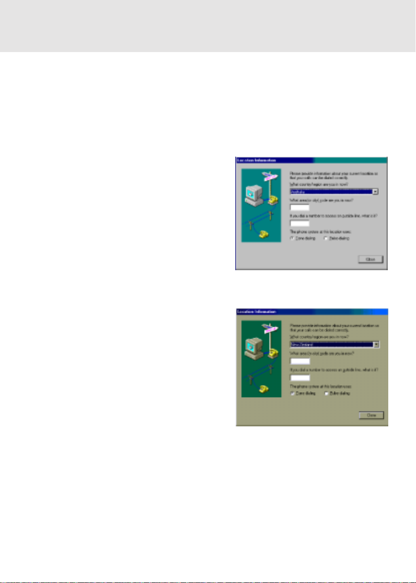
Note: Modem setting in Windows 98 / Windows Me
The default modem setting in Windows 98 / Windows Me operating system is United States of
America. If you are residing in Australia or New Zealand, please choose the appropriate country
where you are located.
The Modem will only operate with Tone Dialing; Selection of Pulse dialing is not possible.
Please see below instruction for quick modem setup.
A. If you are located in Australia
1. Go to Control panel, select modem icon.
2. Choose Australia in “What country/region
are you in now?”
3. Select Phone system as “Tone Dialing”
4. Close
B. If you are located in New Zealand
1. Go to Control panel, select modem icon.
2. Choose New Zealand in “What country/
region are you in now?”
3. Select Phone system as “Tone Dialing”
4. Close

NOTATION IN THIS DOCUMENT
Warnings
This manual uses a variety of icons as visual marks so that you can use this computer safely and
correctly and avoid damage and danger to yourself and to others. These icons and their meanings are as follows. Please learn these icons before reading this manual. Learning these icons
will be useful for understanding this manual.
Icon Meaning
WARNING
CAUTION
The symbols below are used together with the icons above to indicate what type of danger or
damage is involved.
symbols Meaning
Incorrect handling ignoring this warning can cause a dangerous situation
that could result in death or severe injury.
Incorrect handling ignoring this warning can cause a dangerous situation
that could result in moderate or minor injury or could result in equipment
damage.
The symbol ∆ indicates a warning or caution. The symbol ∆ indicates the
concrete nature of the warning. (The e xample on the left is a caution f or
electric shock.)
The circle and slash indicates prohibited behavior. The symbol inside
the circle indicates the concrete nature of the prohibition. (The example
on the left indicates that disassembly is prohibited.)
The indicates instructions that must be followed. The symbol inside
indicates the concrete nature of those instructions. (The e xample on the
left tells you to unplug the power plug from the socket.)
Key notation and operation methods
Explanations of key operations do not show all the characters on the keyboard. Instead they
indicate just the keys necessary to the explanation as follows.
Examples: [Ctrl] key, [Enter] key, [ → ] key
When multiple keys are to be pressed at the same time, this is indicated b y connecting them with
[+].
Examples: [Ctrl] + [F3] keys; [Shift] + [ ↑ ] key
Screen examples
The screens shown in this manual are examples. Please understand that the file names and
screens you use may be different.

Notation in text
Here is what symbols in text mean.
Symbol Meaning
Critical Points
Critical Point Indicates a point necessary for correctly operating the
hardware or software.
Column Gives the meaning and brief explanation of a term.
Column
→ Indicates the page to see elsewhere in this manual.
Command input (key input)
Within the text of this manual, command input (giving commands to the computer by pressing
keys) is indicated as follows.
Example:
In the position indicated in the example above by the ↑, the space left between the characters
indicates that a space needs to be left in the entry by pressing the space bar (the long key with
nothing written on it at the center of the front of the keyboard). Commands are written in this
manual as lowercase latin letters, but uppercase letters may be used.
Product names
The following product names are abbreviated as follows in this manual.
“Microsoft® Windows® 2000 operating system” is written as “Windows 2000”.
“Microsoft® Millennium® Edition operating system” is written as Windows Me”.
“Microsoft® Windows® 98 operating system” is written as “Windows 98”.
“Microsoft® MS-DOS® operating system Version 6.2/V” is written as “MS-DOS”.
“Microsoft® Windows® operating system Version 3.1” is written as “Windows 3.1”.
“Microsoft® Windows NT® Workstation operating system Version 4.0” is written as
“Windows NT 4.0”.
“Microsoft® Windows NT® Workstation operating system Version 3.51” is written as
“Windows NT 3.51”.
“Windows NT 4.0” and “Windows NT 3.51” are both written as Windows NT.
“LifeBook” is written as “this computer” or “the computer main unit”.
dir c:
↑

Configuration of this Manual
SECTION 1
This section explains basic operations and basic items for using this computer, including the
names of the parts and their functions, flat point operation methods, floppy disk unit handing, and
battery operation.
SECTION 2
This section explains installation of options for this computer.
SECTION 3
This section explains what to do when trouble occurs with this computer and when messages are
displayed. Read this section as the necessity arises.
SECTION 1
SECTION 2
SECTION 3

CONTENTS
SECTION 1
1. Names of the Parts and their Functions..........................2
Front .............................................................................................. 2
Right Side ......................................................................................5
Left Side ........................................................................................ 7
Rear/Bottom .................................................................................. 8
One-touch Buttons / CoolView / CoolScroll .................................10
2. Keyboard ..........................................................................14
Keyboard ..................................................................................... 14
Numeric Keypad Mode ................................................................14
Names of the Main Keys and their Functions.............................. 15
3. Turning on the Power ......................................................18
Turning on the power ................................................................... 18
4. Turning off the Power ......................................................20
Turning Off the Power ..................................................................20
5. Suspend/Resume Function ............................................22
What Is the Suspend/Resume Function? ....................................22
Precautions for Suspending......................................................... 22
Suspending..................................................................................23
Using the Resume Function ........................................................ 25
Battery Charging.......................................................................... 26
6. Battery ..............................................................................26
Battery Operation ........................................................................ 27
Checking the Remaining Battery Charge .................................... 28
Low Battery State ........................................................................ 29
Replacing the Battery Pack ......................................................... 30
Bridge Battery .............................................................................. 32
Precautions for Battery Pack .......................................................33
7. Floppy Disk Drive ...........................................................34
Loading/Ejecting a Floppy Disk ................................................... 34
What is a Floppy Disk? ................................................................ 35
Precautions on Handling ............................................................. 36
8. CD-ROM Drive..................................................................37
CD-ROMs ....................................................................................37
Loading/Ejecting a CD-ROM ....................................................... 38
9. Internal Fax Modem.........................................................40
What is a Fax Modem?................................................................ 40
Connection .................................................................................. 40
Modem Warnings......................................................................... 41

SECTION 1
SECTION 2
10. SPDIF Features ..............................................................42
How to use the SPDIF Output Connector?.................................. 42
1. Options .............................................................................44
Options ........................................................................................ 44
2. PC Cards ..........................................................................46
Precautions for PC Cards ............................................................ 46
Installing PC Cards ...................................................................... 47
Removing PC Cards .................................................................... 48
3. Expansion RAM Modules................................................49
Installing an Expansion RAM Module .......................................... 49
Removing an Expansion RAM Module ........................................ 51
4. Mouse ...............................................................................52
Connecting the Mouse................................................................. 52
Using the Mouse.......................................................................... 52
5. Numeric Keypad / Keyboard / Mouse ............................54
Connecting a Numeric Keypad / Keyboard / Mouse .................... 54
6. Printer ...............................................................................55
Connecting a Printer .................................................................... 55
7. CRT Monitor / TV ..............................................................57
Connecting an External CRT Monitor .......................................... 57
Connecting to a TV ...................................................................... 58
SECTION 3
8. Wireless Mouse................................................................59
Precautions on safety ..................................................................59
Preparation and Preliminary knowledge ...................................... 61
Setup of personal computer and wireless mouse........................ 62
Replacing batteries ...................................................................... 63
For good maintenance................................................................. 64
Caution ........................................................................................ 65
Troubleshooting ........................................................................... 65
Specifications .............................................................................. 66
1. When This Happens .........................................................68
2. Care and Maintenance ....................................................73
3. Glossary ...........................................................................78

SECTIONSECTION
SECTION
SECTIONSECTION
SECTIONSECTION
SECTION
SECTIONSECTION
11
1
11
11
1
11
This section explains basic
operations and basic items for
using this computer, including
the names of the parts and their
functions, Flat point operation
methods, floppy disk unit
handing, and battery operation.
SECTION 1
SECTION 1
SECTION 1
1. Names of the Parts and their Functions
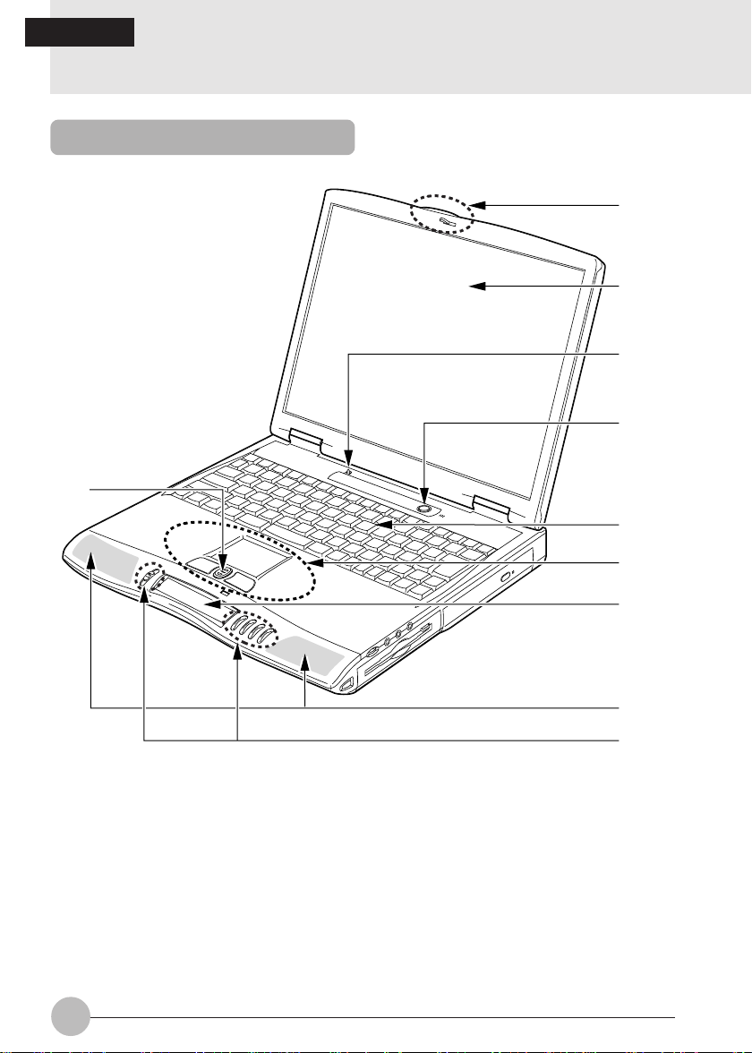
Front
!
1
2
3
4
5
6
7
8
9
2

1 Display Panel Latch
Locks the LCD panel so that it will not inadvertently be opened. To unlock and open the LCD
panel, slide this latch to the right.
2 Liquid Crystal Display (LCD) Panel
Shows a screenful of data from the computer main unit.
Critical Points
About the characteristics of the LCD panel
Note that the following symptoms reflect the characteristics of the LCD and imply no hardware
problem:
The TFT color liquid crystal display of this personal computer is made up of more than 441
million pixels (dots) (at 1,400x1,050 dots resolution) or 235 million pixels (at 1,024x768 dots
resolution) which are fabricated using an advanced technology. Consequently, the display
may have some pixels that will not turn on or that always stay on. Such pixels do not imply
any display failure and should not be regarded as defective.
The liquid crystal displays used in the personal computers of this model may hav e diff erent
hues for reasons associated with the fabrication processes. Your liquid crystal display may
characteristically bear some color shadings due to changes in the ambient temperature.
3 Closed Cover Switch
Used to place the personal computer into the Standby (Suspend) or Resume mode or to turn
off the backlight of the LCD when you open or close the LCD.
4 SUS/RES Button
Used to turn on the personal computer and to place it into the standby or resume mode.
5 Keyboard
Used to type in letters and give commands to the personal computer.
6 Flat Point
Used to manipulate the mouse pointer. Pressing the scroll button at the center causes the
screen to scroll up or down.
SECTION 1
Critical Points
The flat point may malfunction due to condensations or moisture formed on its surface. The
mouse pointer may not function normally if you manipulate it with a wet or sweaty hand or if
the surface of the flat point is dirty . In such a case, turn off the personal computer and clean it
with a soft cloth moistened with mild neutral detergent.
Depending on the application you are using, you may not be able to scroll the screen using
the scroll button.
3

7 CoolView
Shows the status of messages from the personal computer, notification on incomming
E-mail with messages and blinking backlight.
8 Speakers
Produce the sound of the personal computer.
9 One-touch Button
Pressed to activate an application or to receive incoming e-mail. This button is also used to
play back an audio CD.
Critical Points
Do not set the MAIN switch to OFF when using the one-touch button.
! CoolScroll
Shows the shotcut programs.
4

Right Side
SECTION 1
1
2
3
4
5
6
Caution
Failure of an attached device or a hideous or deafening sound may cause harmful
effects on your ears. Set the volume control on your personal computer’s main unit to
its minimum before plugging a cable into the HEADPHONE, LINE IN, or MICRO IN
jack.
1 Volume Control
Adjusts the volume of the speakers. Turning the volume control anti clockwise raises the
volume and turning it clockwise reduces the volume. If you can hear no sound when you
adjust the volume control, keep pressing [F3] while holding down [Fn] until y ou hear a beep .
Also make sure that the volume setting in the [V olume Control] dialog bo x is not set to “Mute.”
You can set the balance and volume of the sound input/output in the [Volume Control] dialog
box. If the volume is f ound inadequate e v en when the volume is set to its maxim um lev el, set
the volume control in the [Volume Control] dialog box.
2 HEADPHONE Jack
Connects to a commercially available headphone (3.5 mm mini-plug). Some models of
headphones may not fit in this jack, how ev er . Make a chec k before purchasing a headphone.
Caution
Take care not to listen over your headphone at too high a volume. Listening over a
headphone at a deafening sound level for an extended period may cause harmful
effects on your ears.
Do not turn on or off your personal computer with a headphone on. A loud pop might
cause harmful effects on your ears.
5

3 Stereo Line-in Jack and Optical Digital Audio Output Terminal
The stereo line-in jack allows you to connect an external audio source. This ter minal also
serves as an Optical Digital Audio Output Terminal.
The Optical Digital Audio Output Terminal allows you to download digital audio onto Sony &
Philips Mini-disc player’s SPDIF (Sony Philips Digital Interface) format.
Important note
Since light is emitted from the optical digital audio output terminal, do not peek into the terminal
when plugging in a cable.
The frequency of the digital audio generated from the optical digital audio output terminal is
fixed at 48 kHz. You can record no sound on any digital device (e.g., MD player) that has no
sampling rate converter built in. For details, refer to the instruction manual attached to the
digital device.
The sound that is recorded on a digital device (e.g., MD player) connected to the optical
digital audio output terminal cannot be output in digital form. All output from the optical digital
audio output terminal is subject to copy protection.
4 MIC IN Jack
Connects to a commercially available microphone for recording (monaural) (compatible with
a 3.5 mm mini-plug). Some models of commercially a v ailable microphones (e .g., mo vingcoil
microphones) are incompatible with this jack. Make a chec k before purchasing a microphone.
5 Floppy Disk Drive
Used to read and write floppy disk data.
6 CD/DVD Drive
Used to read in CD-ROM data and play back audio CD.
A CD-R/RW drive can rewrite CD-R/RW data and a DVD-ROM drive can play back DVD
video or read in DVD-ROM data.
6
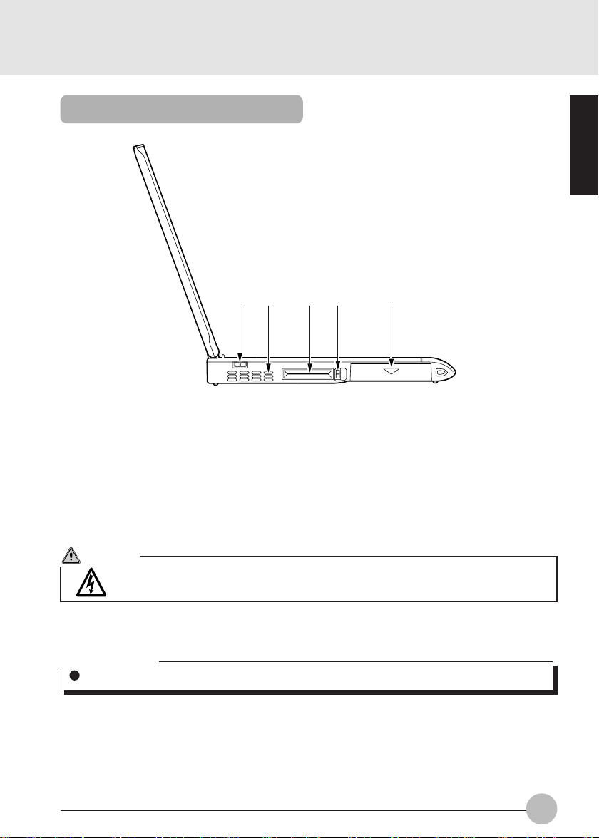
Left Side
12 34 5
1 MAIN Switch
The main power switch of the personal computer.
2 Cooling Fan
Used to vent hot air out of the personal computer interior. The fan starts rotating when the
temperature inside the personal computer increases to a certain level.
SECTION 1
Caution
Do not block the vent of the cooling fan. The heat would stagnate inside the personal
computer, causing machine failures.
3 PC Card Slots
Used to house optional PC cards. The lo wer slot is designated as slot 1 and the upper slot as
slot 2.
Critical Points
In some optional OSes, “slot 1” is referred to as “slot 0” and “slot 2” as “slot 1.”
4 PC Card Eject Button
Pressed to eject a PC card.
5 Built-in Battery Pack
Houses a built-in battery pack.
7

Rear/Bottom
1
3
2
4567890 !
@
8

1 Theft Prevention Lock Slot
Can accept a commercially available theft prevention cable.
Critical Points
The theft prevention lock is compatible with the Kensington microsaver security system.
2 Extended Keyboard/Mouse Connector
Connects to an optional keyboard or mouse.
3 Parallel Connector
Connects to an optional printer.
4 IEEE 1394 (DV) Terminal
Used to connect between the personal computer and a peripheral, such as digital video
camera (DV), with a DV cable.
5 USB Connector
Connects to a USB compatible peripheral such as a USB mouse.
6 S Video Output Terminal
Used to transmit the S video signal.
7 External Display Connector
Connects to an external display such as an optional CRT display.
8 Infrared Port
The fast IrDA compatib le port allows you to communicate with another IrDA compatib le infrared
device without cable.
SECTION 1
9 Modular Connector
Used to connect between the personal computer and a telephone line with the attached
modular cable for communication with a BBS or the Internet.
! Serial Connector
Connects to an RS-232C compatible device.
" DC-IN Connector
Accepts the attached AC adapter.
Important note
When cabling a peripheral device, check the orientation of its cable connector and plug it
straight into the mating connector.
# Expansion RAM Module Slot
Used to house an optional memory module.
9

One-touch Buttons / CoolView / Cool Scroll
78564
9! %&( ) ~+,"-$
(1)
(2)
(3)
(4)
12 3
1 Mode Switch
The position of the Mode Switch determines the functionality of the one-touch buttons.
Set the Mode Switch at the center when you are not using one-touch button.
2 CoolView
Shows the status of and messages from the personal computer.
10

3 One-touch Buttons
The one-touch buttons are used to start applications, control audio CD, with the display
panel closed. The functionality of the one-touch b uttons is determined as summarized in the
table below depending on the position of the Mode switch.
Mode Switch Button
Position (1) (2) (3) (4)
Application Button A Button B Internet button E-mail button
(Upper)
Lock (Center) All buttons are disabled. Prevents a button from being pressed
inadvertently.
CD Player (Lower) Stop/Eject Play/Pause Fast Backward Fast Forward
While Windows 98 is activ e, the CD Play er one-touch buttons are interlocked with the actions
of the CD player buttons, except the Eject button.
While Windows 98 is not active , the CD Pla y er one-touch buttons are interloc ked with action
of the CD player buttons.
Critical Points
For instructions to change an application assigned to a one-touch button, see the Lifebook
Application Panel Software installed in your computer
If you changed settings so that the EJECT function is activated when the button is pressed,
do not press the button while you are using a CD. An error window might appear.
4 Mode Display
As you switch the Mode switch f or the one-touch buttons, the current mode is sho wn enclosed
in a box.
SECTION 1
Critical Points
The mode is not shown if the MAIN switch is set to OFF.
5 CD Mark
The mar k revolves when you play back an audio CD when the personal computer is in
the standby mode or at the end of Windows.
11

6 CD Track Display
The number of the track on playbac k is shown when an audio CD is being pla y ed back using
the one-touch buttons for the CD player.
• Numerals
Indicate the track number of the track on playback. The track number of the first track is
indicated when the CD player is in the stopped state.
•— —
Appears when no audio CD is set or when an audio CD is being read.
• SP
Appears when the personal computer is in the power save mode . Pressing the button
restores the CD player in the state in which you can manipulate the audio CD.
7 Volume Level Display
Indicates the volume you set up with the volume control in 8 increments.
Critical Points
There may be times when the volume setting y ou made with the v olume control do not agree
with the volume level display.
8 Message Display Area
Shows various messages depending on the situations such as when the personal computer
is started and when e-mail arrives.
9 SUS/RES ( )
Stays on when your personal computer is running and flashes when it is in the standby
mode.
! AC Adapter ( )
Stays on when power is being supplied from the AC adapter.
" Battery ( 1. )
Stays on when a battery is installed.
# Battery Charging ( )
Stays on when the battery is being charged. Flashes when the battery is not being charged
because it is too hot or cold.
$ Battery Level ( )
Indicates the charge level of the battery.
% Hard Drive Access ( )
Stays on when the internal hard disk drive is being accessed.
& CD Access ( )
Stays on when the CD is being accessed.
12

( Floppy Disk Drive Access ( )
Stays on when the floppy disk is being accessed.
) PC Card Access (
Stay on when the corresponding PC card is being accessed.
~ Num Lock (
Stays on when the keyboard is in the n umeric lock mode. Press [Num Lk] to turn on and off
the numeric lock mode.
+ Caps Lock (
Lights up when the personal computer is placed into the Caps Lock mode (letters are entered
all in uppercase). Press [Caps Lock] while holding down [Shift] to tur n on and off the Caps
Lock mode.
1 2
) Indicator
1
) Indicator
A
)
, Scroll Lock ( ) Indicator
Lights up when the personal computer is set up so that the screen will not scroll at all (scroll
lock). Press [Scr Lk] while holding down [Fn] to tur n on and off the scroll lock mode. The
operation of the personal computer depends on the application that is being executed.
Critical Points
Data on the hard disk drive or floppy disk drive may be corrupted if you turn off the MAIN
switch or manipulate the SUS/RES switch when the Hard Disk Drive Access or Floppy Disk
Drive Access indicator is on.
While the MAIN switch is set to OFF, all CoolView illuminators are off except when the battery
is being charged.
Under some optional OSes, PC Card Access display “Slot 1” may appear as “Slot 0” and
“Slot 2” as “Slot 1.”
Checks for the presence or absence of a CD are made periodically if the automatic CD insertion
feature is enabled. Accordingly, the CD Access illuminator on the CoolView lights periodically .
Follow the steps shown below to disable the automatic CD insertion feature.
1 Click [Start], [Settings], and [Control Panel] in that order.
2 Click [ ] (System).
3 Click the [Device Manager] tab.
4 Click [ ] to the left of [CD-ROM].
A CD-ROM device will appear.
5 Click the CD-ROM device and click [Properties].
The [CD-ROM Device Properties] dialog will box appear.
6 Click the [Settings] tab .
7 Click and uncheck [Automatically notify insertion] under “Options.”
8 Click [OK].
9 Click [OK] or [Close] in the [System Properties] dialog box.
You will be brought back to the [Control Panel] window.
10 Restart the personal computer.
SECTION 1
To re-enable automatic CD insertion, click and check [Automatically notify insertion] in Step 7.
13
SECTION 1
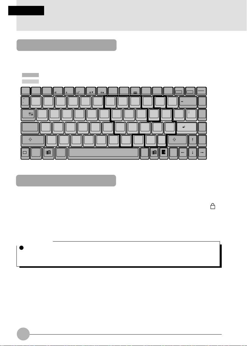
2. Keyboard
Keyboard
The keyboard is the device for giving instr uctions to the computer, inputting data, and executing.
The keys can be divided into two types.
: Control keys
: Character keys
Num Lk
Insert
Delete
F1Esc F2 F3 F4 F5 F6 F7 F8 F9 F10 F11 F12
_
@
!
12
QWE RTYUI OP
Tab
CapsLock
Shift Shift
Fn
Ctrl Alt
#3$4%5^
ASDFGHJ KL
ZXCVBNM<,>
&
67
789
456
*8(
123
0
)
90
.
Alt Ctrl
-
-
:
;
/
Scr Lk
{]}
[
Enter
?
/
Prt Sc
+
=
"
'
*
SysRq
Backspace
\
Enter
Pause
Break
Home
Pg Up
Pg Dn
End
Numeric Keypad Mode
The mode in which some of the character keys are used as numeric keys (with a key layout that
makes numeric input easier) instead of their normal functions is called numeric keypad mode. The
keyboard is switched to numeric keypad mode with [Num Lk]. (In numeric keypad mode, 1 is
displayed on the status indicator LCD.) The keys surrounded by thick lines in the diagram above
become the numeric keypad. The numbers input with these keys are printed in pink on the front of
each key.
Critical Point
When the separately sold numeric keypad is connected, if you press [Num Lk] to put the
computer into numeric keypad mode, the keys on the external numeric keypad are enabled,
but the numeric keypad section on the keyboard is disabled.
14

Names of the Main Keys and their Functions
[Esc] (escape) key
The usage is determined by the application software. It is often used to return to the
previous operation.
[F1]-[F12] (function) keys
The usage depends on the application software.
[Fn] key
A key unique to this computer; it has the following functions.
[Fn] + [F3] This switches ON/OFF of the speaker.
When a pip sounds with this operation, the speaker is on. When nothing
sounds, the speaker is turned off.
This select to disabled the touch pad mouse when you attached an
external mouse.
[Fn] + [F5] This selects whether or not to use the entire LCD display panel f or display
in text mode.
[Fn] + [F6] Turns down the backlight of the LCD.
[Fn] + [F7] Turns up the backlight of the LCD.
Critical Point
Luminance of the backlight of the LCD can be turned up (with [Fn] + [F7] keys) or turned
down (with [Fn] + [F6] keys) in three degrees.
[Fn] + [F10] Rotates among the three display options: LCD only, CRT only , both LCD
and CRT.
[Space] key
Inputs a single space character.
(This is the long key with nothing written on it at the center of the front of the ke yboard.)
SECTION 1
[↑] [↓] [←] [→] (cursor) keys
Move the cursor.
[Enter] key
Also called the return key or the line feed key. This key inputs line feeds and executes
command.
[Ctrl] (control) key
Used in combination with other keys; its functions depend on the application software.
15

[Shift] key
Used in combination with other keys.
[Alt] key
[Caps Lock] key
[Num Lk] (numerical lock) key
[Scr Lk] (scroll lock) key
[Print Screen] key
[Pause] key
[Break] key
[Insert] key
[Delete] key
Used in combination with other keys; its functions depend on the application software.
To lock the keyboard into caps mode, press the Caps Lock key. Pressing this key again
ends caps mode.
Press this key to put the computer into numeric keypad mode.
Its functions depend on the application software.
Press this key to make a hard copy of the screen.
Press this key to pause the screen display.
Its functions depend on the application software.
Press this key to insert a new character between characters. The new characters are
entered at the cursor position.
Press this key to delete a character . Pressing the Delete key and the [Ctrl] and [Alt] keys
at the same time resets this computer.
[Home] key
[End] key
[Page Up] key
[Page Down] key
[Back Space] key
Press this key to move the cursor directly to the head of the row or the head of the
document.
Press this key to move the cursor directly to the end of the ro w or the end of the document.
Press this key to switch to the previous screen.
Press this key to switch to the next screen.
Press this key to delete the character to the left of the cursor position.
16

[Sys Rq] (system request) key
When this key is supported by the application software, this ke y is used for such functions
as resetting the keyboard. Press this key together with the Alt key.
[ ] (Windows) key
Press this key to display the Start menu.
[ ] (Application) key
Press this key to display the shortcut menu for the selected item. This key has the same
role as the mouse right click.
SECTION 1
17
SECTION 1
3. Turning on the Power
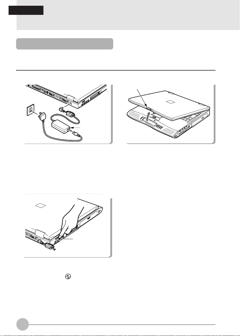
Turning on the power
This item explains the normal way to turn the computer main unit power on and off.
1 Connect the AC adaptor.
AC adaptor
3 Switch on the main switch of the
computer main unit.
MAIN switch
2 Open the LCD display panel.
Latch
Pull the latch to release the lock, then lift the
display panel with your hand.
Power is supplied from the A C adaptor or the
battery, the power comes on, and the POST
starts. Also, the etc. on the status
indicator LCD are displayed.
18

Critical Point
Do not carry this computer around or subject it to shock or vibration with the power on. These
can result in breakdown.
Column
POST is the abbreviation for POWER ON SELF TEST, which is a self-diagnostic test that
checks for abnormalities within the computer. This test is automatically carried out when the
power is switched on for this computer. If the power is switched off during the POST, an error
message is displayed the ne xt time the computer is started up. Do not cut off the po wer during
the POST.
SECTION 1
19

SECTION 1
4. Turning off the Power
Turning Off the Power
This item explains how to turn off the power.
Critical Points
Do not turn back on the computer immediately after turning it off, but wait for 10 seconds or
so.
When the computer is not used for a long time, unload the flopp y disk and the CD-R OM from
the computer before turning it off.
1 Click the [Start] button.
The Start menu is displayed.
2 Click [Shut Down].
The following message is displayed.
3 [Check that Shut down the computer is selected, then click OK].
The power is turned off. If the computer will be unused for a long period, disconnect the AC
adaptor.
20

Critical Points
If the MAIN switch is not turned off after the step 3, press the SUS/RES button to turn on the
personal computer next time.
If “Restart” or “Restart computer” is selected on the dialog box that appears as a result of the
steps 2, the personal computer will be restarted. “Restart” means that the personal computer
erases all data saved in the memory once and again reads the program of the operating
system from the floppy disk or hard disk into it.
4 Turn off the MAIN switch.
Slide the MAIN switch in the direction of the
arrow (toward side).
MAIN switch
Critical Point
If the personal computer won’t be used for a long time after this step, be sure to disconnect
the AC adaptor and to remove the battery pack from it.
SECTION 1
21

SECTION 1
5. Suspend/Resume Function
What Is the Suspend/Resume Function?
When this computer is suspended with the SUS/RES button, the suspend/resume function retains
the programs and data in memory as is so that you can resume operations immediately the next time
you press the SUS/RES button.
Precautions for Suspending
Pay attention to the following points when using the suspend function.
Do not hold down the SUS/RES button for more than 4 seconds, otherwise the computer will
be turned off.
When the computer is connected to a network using a LAN or modem and when the peripheral
equipment is expanded with a PC card, you may not be able to use the suspend/resume
function. When you have expanded functions with a PC card, also check the manual for the
cards you are using.
Do not operate the SUS/RES button when using Windows NT.
In the following cases, do not use the suspend function, b ut turn on/off the computer main unit
power supply with the main switch.
• When this computer is unused for a long period
When this computer will be unused longer than the effective period (about one da y maximum)
for battery power for suspend mode, sa ve all data, close Windows 98, then turn off the main
switch. If you suspend with the BIOS setup Suspend Mode set to Save to Disk, the power
goes off with the main switch still on. In this case , it does not matter if you turn off the main
switch. The next time you tur n on the main switch, operation resumes.
• When installing or removing options
There are some options that can be installed without turning off the main switch. See
SECTION 2 of this manual and the manual that comes with the option product.
Critical Points
The SUS/RES button does not work in the following cases.
If the battery is dead while the computer is powered from it.
When the BIOS setup SUS/RES button is set to disabled.
22

Suspending
There are three ways to suspend this computer, using the SUS/RES button, Closed Cover
switch and using the [Shut Down] dialog in Windowa 98 / Windows Me
Using the SUS/RES button
1 Suspending
Check that and are out. When you
press the SUS/RES button, flashes
and the computer goes into suspend
mode.
SUS/RES button
Critical Points
Which of the two destinations suspending saves the data in the computer to depends on the
BIOS setup Power menu setting as follows.
System RAM:
When “Suspend” is set with the BIOS setup Power menu “Suspend Mode” item, the data
is saved to system RAM. P o wer f or the system RAM is supplied from the AC po wer supply
if the AC adaptor is connected or from the battery if the AC adaptor is not connected.
Save to Disk area:
If “Save to Disk” is set with the BIOS setup Power menu “Suspend Mode” item, the data is
written to the Save to Disk area on the hard disk.
If you hold down the [Fn] key while pressing the SUS/RES button, the data is saved to the
hard disk regardless of the Power menu setting.
SECTION 1
23

Using the Closed Cover switch
1 Close the LCD display panel.
This unit goes into suspend mode using the Closed
Cover switch.
Critical Point
When the BIOS setup “Lid Closure Suspend” setting
is “Disabled”, this unit does not go into suspend mode
even if you close the LCD display panel.
Using the [Exit Windows] dialog box.
1 Click on the [START] button, then on
[Exit Windows].
The [Exit Windows] dialog box will appear on the
screen.
2 Choose [Standby] and click on [OK].
This computer is suspended.
Critical Points
If the BIOS setup Suspend Mode setting is “Suspend”, suspend mode is ended in the following
cases. Save important data to a floppy disk or the hard disk.
• The main switch is switched off.
• In battery operation, the battery runs out.
(The battery is still used in suspend mode.)
If you start with the internal battery fully charged, suspend mode lasts about one day maximum
with the AC adaptor not connected.
24

Using the Resume Function
You can make the computer resume the current application program, using either the
SUS/RES button or the closed cover switch.
Critical Point
Immediately after putting it into the Suspend mode, do not make the computer resume the
program but wait for 10 seconds or so.
Using the SUS/RES button
1 Press the SUS/RES button.
Pressing the SUS/RES button will cause the
indicator on the status display panel to stop
blinking and light up permanently , and will bring the
computer into operation.
SUS/RES
Using the closed cover switch
1 Open the LCD display.
Opening the LCD display will turn on the Cover
Close switch and make the computer resume the
current program.
Latch
button
SECTION 1
Critical Point
The Resume function does not operate if Lid Open
Resume in the BIOS Setup dialog box is not selected.
25

SECTION 1
6. Battery
Battery Charging
For portability, this computer can operate either from the AC adaptor or from its battery.
This item explains how to charge the battery.
1 Connect the AC adaptor.
AC adaptor
Relationship between computer modes and battery charging time
Main switch SUS/RES button Computer mode Charging mode Charging time
ON
OFF
Resume Standard charging
Suspend
––
Operating mode
Suspend mode
1
2
During charging,
status indicator LCD and the remaining battery
charge is displayed.
Stopped
is displayed.
1
1
Quick charge
is displayed on the
About 9 hours
About 3 hours
Critical Points
When the battery charge indicator ( ) goes out and status of the remaining battery power
indicator on the left side changes from blinking ( ) to continuous lighting ( ),charging
the battery is complete. Spend considerable hours for charging the battery so that it is fully
charged.
The battery capacity falls if the ambient temperature is too low or too high.
Just after use of the battery , charging it ma y result in f ailure because the battery temperature
has risen and the battery protection function is activated. In such the case, leave the battery
in the charging status and charging will start a while later with drop of the battery temperature.
26

Battery Operation
This item explains operation with the battery.
1 Disconnect the AC adaptor and s witch on
the main switch.
Main Switch
2 When the main switch is on, press the
SUS/RES button.
SUS/RES switch
stops flashing and stays lit up.
Critical Points
When the ambient temperature is lower, the battery operating time is reduced.
With this computer, the battery operating time depends on the conditions under which the
battery is used. However, the operating time of a new, fully-charged battery is about 1.5 to 3
hours.
Condition: Main unit only, full charge, with power management on.
(The yardstick for operating time depends on the conditions of use.)
SECTION 1
27

Checking the Remaining Battery Charge
This computer can indicates the amount of battery charge remaining with the remaining battery
charge indicator on the status indicator LCD.
Remaining battery charge indicator
Indicates battery charge level of about 76% to about 100%
Indicates battery charge level of about 51% to about 75%
Indicates battery charge level of about 26% to about 50%
Indicates battery charge level of about 16% to about 25%
Indicates the low battery state (battery charge level of about 15% or
lower). flashes.
Indicates that the battery has run out (0% charge level).
Battery abnormality indicator
Indicates that the battery can not be charged normally.
Critical Point
When is displayed, take out the battery pack and re-install it. If this displa y still remains,
the battery pack is abnormal, so replace it.
28

Low Battery State
This item explains the display when this computer’s battery is low and what to do.
1 The low battery is announced in the following way.
The warning beeps and the battery mark on the status indicator LCD flashes.
Critical Point
If the audio volume is set too low, you may not be able to hear the warning beep. When the
speaker is set to OFF using [Fn] + [F3] keys, the warning beep does not sound.
2 Press the SUS/RES button.
When the battery goes low, quickly press the SUS/RES button to suspend operation. Since
the suspend/resume function works even if the computer is suspended during operation, the
program and data are not lost.
Critical Point
If you want to resume operation immediately, connect the AC adaptor, then press the
SUS/RES button again.
3 Charge the battery.
Connect the AC battery to charge the battery.
Critical Points
Reading from and writing to the hard disk uses large amounts of power . When saving data to
the hard disk with the battery low, connect the AC adaptor.
If you leave this computer running with the battery low , it is suspended automatically . How ever ,
if data is being read from or written to the hard disk or other media, the suspending waits until
that processing is complete.
If you continue using the computer with the battery low, in the worst case, the data being
created or saved may be lost. Quickly connect the AC adaptor.
SECTION 1
29

Replacing the Battery Pack
W ARNING
(ELECTRIC SHOCK)
Before replacing the battery
pack, be sure to turn off the
computer and disconnect the
AC adaptor from it.
Otherwise you might get an
electric shock.
2 Slide the cover of the battery pack.
Battery pack
1 T urn off the computer and disconnect the
AC adaptor from it.
3 Slide the battery pack towar ds you (in the
direction opposite to the connector).
Connector
Battery pack
30
Cover
The battery pack is disconnected from the
connector of the built-in battery pack slot.

5 Install a new battery pack.4 Remove the battery pack.
SECTION 1
Battery pack
Tilt the battery pack up and then take it
out of the battery pack slot in a tilt
direction.
Battery pack
Connector
Battery pack
Slide
guide
Put the battery pack in the slot by positioning
the slide guide with the main unit.
7 Slide the battery pack cover.6 Connect the connector.
Battery pack
Cover
While tilting up the battery pack cover,
slide the battery pack and connect the
connector.
For locking the battery pack cover that was
once slid in the previous step 2, again slide
it to its original position.
31

Bridge Battery
The bridge battery is a NiCd battery that is built-in your notebook and is constantly being recharged.
A bridge battery allows a charged Lithium ion battery to be exchanged for a discharged one by
“warm-swapping”.
To warm-swap have a charged battery ready , put y our notebook in Suspend mode , remo v e the low
battery and quickly insert a charged battery. The bridge battery capacity is not large, about 3 minutes, and can vary with the condition of your notebook.
Caution
Data may be lost and/or system errors introduced if the warm swap is not perfor med
quickly or a power adapter installed
Caution
The bridge battery can not suppor t an operating notebook. The notebook must be in
Suspend mode.
32

Precautions for Battery Pack
W ARNING
(ELECTRIC SHOCK)
The battery pack is an extremely delicate products. When installing or removing one, do
not drop it or subject it to strong shocks. If this should happen, do not use that battery
pack in the interest of safely, because there is a risk of electric shock or malfunction.
Discharge
After you charge the battery pack, even if y ou store it without using it, o v er about 1 month it will
naturally discharge.
Service life
•The battery pack is a consumption item. After you use it f or a long time, its charging capacity
drops.
•Replace the battery after about 300 to 500 charge/discharge cycles.
•When the battery operating time becomes extremely short, the battery has reached the end
of its service life.
To extend the battery operating time
Use the BIOS setup Power menu.
Conditions under which the battery operating time becomes shorter
•Using in cold or hot location
The battery operating time is influenced by the environmental temperature and the battery
operating time can be shorter at low temperature (5°C) then at high temperature (35°C).
Also, high temperatures not only lower the charging efficiency, but are also a cause of battery
pack deterioration.
•When the battery charging capacity drops
When the battery pack has been used for a long time, its charging capacity drops. In this
case, replace it with a new battery pack.
SECTION 1
Use the AC adaptor in the following cases
• When using the hard disk or CD-ROM frequently
• When using a LAN or a modem
33

SECTION 1SECTION 1
7. Floppy Disk Drive
Loading/Ejecting a Floppy Disk
This item explains how to load and eject a floppy disk.
Loading
Insert into the floppy disk drive.
Insert the floppy disk with the label
upwards and the shutter side first until the
EJECT button springs out.
Critical Points
If you eject the floppy disk while is still
indicated, there is a risk of losing the data on
the disk.
When you do not want to erase the data sav ed
on the disk, or when you do not want to write
additional data, slide the floppy disk’s write
protector so that the hole is open (WRITE
PROTECT state). When you want to write
data again, slide the write protector so that
the hole is closed.
Eject
button
Ejecting
Press the EJECT button.
Eject
button
Check that the on the Status Indicator
LCD is not on, then press the EJECT button.
Write protector
WRITE ENABLE
WRITE PROTECT
34

What is a Floppy Disk?
A floppy disk is a medium for storing programs or data. This item explains basic knowledge
and precautions regarding floppy disks.
Types of floppy disks
If floppy disks are classified according to the amount of data they can store (the memory
capacity), typically there are the following 2 types.
•2HD floppy disks
These have 1.44MB (megabyte: unit of data
amount) and 1.2MB memory capacities.
• 2DD floppy disks
These have 720KB (kilobyte) memory
capacities, half of the 2HDs.
The differences between the 2 kinds of floppy
disks are shown in the diagram on the right.
3 mode drive
This computer’s floppy disk drive is a 3 mode drive that can read 1.44MB, 1.2MB and 720KB
memory capacity floppy disks. Therefore it can read nearly all floppy disks. However, when
exchanging data with another computer, you have to be careful if the other computer’s floppy
disk drive is not a 3 mode drive. For example, if the other computer can read 1.2MB floppy
disks but not 1.44MB floppy disks, y ou hav e to enter the data after putting it into 1.2MB f ormat
in advance with this computer.
HD mark or no mark
2HD 2DD
Hole or no hole
SECTION 1
Critical Point
Some floppy disks cannot be read by this computer, depending on the floppy disk format.
35

Precautions on Handling
Take the following precautions when using floppy disks in order to avoid damaging them.
Be careful not to spill liquids such
as coffee onto them.
Never touch the surface of the
disk.
Do not place them in places with
high temperatures or in direct
sunlight.
Do not bring them near to
magnetic fields.
Do not bend them or place heavy
objects on top of them.
Do not stick labels on over each
other.
36

SECTION 1
COMPACT
DIGIT A L AUDIO
8. CD-ROM Drive
CD-ROMs
Take the following precautions when handling CD-ROMS.
When removing a CD-ROM from its case, lift it
out while pressing the center holder of the case,
as in the diagram on the right.
Handle the CD-ROM by its edges, trying as much
as possible not to touch the surfaces.
Store the CD-ROM in its case when not using it.
Do not leave it in a high temperature place.
Do not bend it or place heavy objects on it.
Do not write with a ballpoint pen, pencil, etc. on
the label surface (printed side).
If you suddenly move the CD-ROM from a cold place such as outside to a warm place,
condensation will form on the surface and the CD-ROM drive will be unab le to read data. If this
happens, wipe the CD-ROM with a dry soft cloth, and then allow it to dry naturally. Do not use
anything like a hairdryer, etc. to dry it.
Critical Points
If the CD-ROM gets dirty , wipe it clean with a dry soft cloth from the center outwards. Do not
wipe it with benzine, paint thinner, water, record spray, antistatic solution or silicon cloth.
A CD-ROM is a ROM that stores computer data
instead of the audio data stored on music CDs
(compact disks).
ROM stands for Read Only Memory, which
means it is a memory medium that can only read
data and cannot write data later. The CD-ROMs
which are marked as in the diagram on the right
can be used with this computer.
A little time is required after installing a CD-ROM until the computer recognizes it.
COMPACT
COMPACT
DIGITAL AUDIO
COMPACT
DIGITAL VIDEO
SECTION 1
37

Loading/Ejecting a CD-ROM
This item explains how to load/eject a CD-ROM.
Critical Point
There is a protective sheet on the
expansion unit’s CD-ROM tray upon
delivery . Remo ve this sheet when you use
the CD-ROM drive.
You can only install/eject a CD-ROM
when the computer main unit is in
operating mode because of the electronic
lock of the CD-ROM drive.
2 Pull the tray out.
1 Press the EJECT button.
EJECT button
The tray springs out slightly.
3 Put in the CD-ROM.
Pull the tray out gently.
38
Place the CD-ROM in the center of the tray
with its label facing upwards.

4 Set the tray.
Push the tray in gently.
Critical Points
CD-ROM drive is an extremely delicate de vice in which the CD-R OM revolves at high speed.
Do not carry it when the power to the computer is switched on, and do not expose it to shoc ks
or vibrations.
When ejecting a CD-ROM, carry out the same procedure as for loading.
If for some reason the tray does not come out when y ou press the eject button, insert something
like a clip into the hole to the right of the EJECT button on the front of the CD-ROM drive unit
and pull out the tray.
SECTION 1
39

SECTION 1
9. Internal Fax Modem
What is a Fax Modem?
A modem is a device for exchanging data between a computer and a telephone line. If you have a
modem, you can carry out computer communications (connecting computers by a telephone line
and exchanging information).
A fax modem is a modem which, in addition to the above functions, has a function of sending data
to a fax machine. Therefore, when you transmit a document to another person’s fax machine, you
don’t have to go to the trouble of printing out the document and setting it in your fax machine.
You can also receive data sent from a fax machine.
Connection
Connect the modular cable jack from the line junction into the modular connector on the rear of the
computer main unit.
Critical Point
When you remove the modular cable,
press down the hook of the modular plug
and pull it out.
Critical Point
If you use a fax modem of the Modem Model (a model which has a built-in modem only), put
the core supplied with the cable on the modular cable in order to reduce unnecessary radiation
of radio wave. Insert the plug with the core into the PC.
1 Twine the cable once around the
core near the plug of modular
cable.
Core
Plug
2 Close the Core.
When closing the core, be careful not
to pinch the cable.
40

Modem Warnings
CAUTION
The internal modem has a maximum speed of 56000bps by ITU-T V.90 standard. Its
maximum speed of 53000bps is the highest allowed by FCC , and its actual connection
rate depends on the line conditions. The maximum speed is 33600bps at upload.
CAUTION
The internal modem is not intended for use with Digital PBX systems. Do not connect
the internal modem to a digital PBX as it may cause serious damage to the internal
modem or your entire notebook.
Consult your PBX manufacturer’s documentation for details. Some hotels have digital
PBX systems.
Be sure to find out BEFORE you connect your modem.
SECTION 1
41

SECTION 1
10. SPDIF Features
How to use the SPDIF Output Connector?
This model comes equipped with an Optical Digital Audio Out connector which allows you to connect
to devices (Sony or Philips MiniDisc players) which supports SPDIF (Sony Philips Digital Interface)
format. The SPDIF function in this system has been set to enabled.
SPDIF Connector
CAUTION
(INJURY)
Do not look into the SPDIF connector when inserting the cable jack into the connector
as there is a strong light beam emitting from the connector.
(BREAKDOWN)
Turn down the audio volume when connecting electronic devices to the Line In jack.
Extremely loud audio volume will cause damage to the internal speakers.
Critical Point
The frequency of the digital sound output from the SPDIF output connector is fixed at 48kHz.
If a sampling rate convertor is not installed in your connected digital electronic device (e.g.
MD player), recording is not possible. Please refer to the user’s manuals for the electronic
devices for further details.
The sound recorded through the connected digital electronic device (e.g. MD player) to the
SPDIF output connector cannot be used as a digital output. All output data from the SPDIF
output connector has copyright protection information included.
Please be careful to use the correct type of cable to connect the digital electronic device
(e.g. MD player) to the SPDIF output connector. The type of connector that is used on your
computer is a Optical Mini Plug (3.5mm diameter mini plug).
42

SECTIONSECTION
SECTION
SECTIONSECTION
SECTIONSECTION
SECTION
SECTIONSECTION
22
2
22
22
2
22
This section explains installation
of options for this computer.
SECTION 2

SECTION 2
1. Options
Options
You can expand the functions of this computer by connecting various options. Connecting options
such as a printer or a modem card makes it possible to print documents created with this computer
and to communicate them to other computers.
Other options include hard disks and expansion memory. Install options to match this computer to
your usage objectives.
TV
Color CRT display
LAN card
CCD camera
USB mouse
Digital
camera
Printer
44
Mouse
Numeric key pad /
Keyboard
Expansion RAM module

WARNING
(ELECTRIC SHOCK)
Only connect equipment recommended by Fujitsu.
Connecting any other equipment can cause electric shock, fire, or breakdown.
CAUTION
(INJURY)
When installing/removing options, do not remove an y screws other than those specified
by this manual.
Removing any other screws can cause injury and breakdown.
(BREAKDOWN)
Read this manual carefully and connect cables correctly. If you use this computer with
cables connected incorrectly , this can cause breakdo wn of the computer main unit and
of the peripheral equipment.
SECTION 2
45

SECTION 2
2. PC Cards
Precautions for PC Cards
Observe the following points when using PC cards to prevent breakdown.
Do not place PC cards in hightemperature locations and
locations subject to direct
sunlight.
Do not place heavy objects on
top of PC cards.
Do not subject PC cards to
strong shocks.
Be careful to avoid spilling coffee
and other liquids on PC cards.
Avoid rubbing PC cards and
building up static electricity.
When storing a PC card, always
place it in its special case.
46

Installing PC Cards
PC card is a generic term for business card sized cards which have a program and data
memory function or peripheral equipment functions such as a modem or LAN adaptor. This
item explains how to install a PC card.
1 Install the PC card.
PC card
Eject Button
Insert the PC card into the PC card slot
with the product name facing upwards.
Critical Points
For some PC cards, the main power s witch should be turned off. Ref er to the manual attached
to your PC card.
In order to avoid damage, be careful not to knock or put anything on top of the connection
point between the PC card and the cord.
SECTION 2
47

Removing PC Cards
This item explains how to remove a PC card.
1 Click the PC card indicator on the task
bar.
A message is displayed for stopping the
installed PC card.
2 Click the PC card to be removed.
The PC card operations stop and the
following screen is displayed.
Critical Point
For IC memory cards, the “This device cannot be removed” message may appear. If this
message does appear, close Windows 98 / Windows ME and turn off the computer main unit
power before removing the IC memory card.
3 Click [OK].
4 Press the PC card eject button.
5 Remove the PC card.
PC card
PC card
PC card eject button
The PC card eject button slightly juts up.
Press the PC card eject button to eject
the PC card.
eject/lock button
Critical Points
Never remove a PC card by pulling on its cord. Yanking on the cord can break the PC card.
Always use the procedure above for removing PC cards. Removing PC cards in any other
way can cause breakdown.
48
SECTION 2
3. Expansion RAM Modules
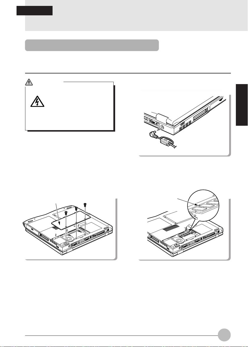
Installing an Expansion RAM Module
This item explains how to install expansion RAM modules.
W ARNING
Always turn off the
computer and disconnect
the AC adaptor when
installing an expansion
RAM module in order to
avoid electric shock.
2 Remove the cover.
Cover
1 Turn off the computer and disconnect
the AC adaptor.
SECTION 2
3 Install the expansion RAM module.
RAM
Take out the screws on the bottom of the
computer main unit and remove the cover.
Align the notch of the expansion RAM
module with the projection on the connector,
insert firmly diagonally from above and push
down until the module clicks into place.
49

4 Fit the cover.
Cover
Fit the cover removed in 2.
CAUTION
The expansion RAM module is made up of parts that are extremely vulnerable to
static electricity and can be damaged by the static electricity built up in the body . When
installing or removing an expansion RAM module, hold it by the edges. Do not touch
any terminals or ICs. Also, do not touch any par ts or terminals within the computer
main unit.
Checking expansion memory
T o chec k expansion memory after installing an expansion RAM module , look at the DIMM item in
the Info menu of the BIOS setup. For example, when a 32MB expansion RAM module has been
installed, the number displayed is 32MB. If the expansion RAM module has been installed
correctly but the number has not increased, it means the RAM module is either broken
or defective. If this happens, contact the store where the RAM module was purchased.
50

Removing an Expansion RAM Module
This item explains how to remove an expansion RAM module.
W ARNING
Always turn off the computer and disconnect the AC adaptor when removing an
expansion RAM module in order to avoid electric shock.
1 Turn off the computer and disconnect
the AC adaptor from it.
3 Remove the expansion RAM module.
Hooks
2 Remove the cover.
SECTION 2
Cover
Remove the cover on the bottom of the
computer main unit.
4 Fit the cover.
Cover
Open the hooks on both sides that retain the
expansion RAM module to the left and right,
then remove the expansion RAM module from
the slot.
Fit the cover removed in 2.
51

SECTION 2
4. Mouse
Connecting the Mouse
1 Turn off the computer and disconnect
the AC adaptor from it.
Main Switch
2 Connect the connector at the end of
the mouse cable to the expansion
keyboard/mouse connector on the rear
side of the computer main unit.
connector
Have the arrow marked on the connector
facing down.
Using the Mouse
Moving the mouse
Place your hand on the mouse so that your fingers are resting on the left and right buttons and
move the mouse by sliding it over your desktop or other smooth surface. The arrow (called the
mouse pointer) on the screen moves in the same wa y as the mouse. Try moving the mouse while
watching the screen.
52

Button operations
• Click
Click
• Double click
Click, click
• Pointing
Press the left mouse button once until it clicks.
The action of pressing the right button once firmly
enough that it clicks is called a “right click”.
Press the mouse left button two times quickly in
a row.
Align the mouse pointer with a menu item. When
there is another level f or the menu item the cursor
is on (when - is displayed at the right of the
menu item), that menu level is displayed.
SECTION 2
• Dragging
Release
Press
Move the mouse pointer with the mouse left
button held down, then release the button at the
desired position.
53

SECTION 2
5. Numeric Keypad / Keyboard / Mouse
Connecting a Numeric Keypad / Keyboard / Mouse
This item explains how to connect a numeric keypad.
1 Turn off the MAIN switch. 2 Connect the numeric keypad.
Main switch
Slide the MAIN switch in the direction of
the arrow (toward side).
Have the arrow marked on the connector
facing down.
connector
Critical Points
When a mouse is connected to the numeric keypad mouse connector , the mouse connector
on the computer main unit cannot be used.
Mouse connector
You can adjust the tilt of the numeric keypad with the tilt feet on the bottom of the numeric
keypad.
54

SECTION 2
6. Printer
Connecting a Printer
This item explains how to connect a printer to the parallel interface connector on the rear of
the computer main unit.
W ARNING
(ELECTRIC SHOCK)
Always turn off the computer main unit and disconnect the AC adaptor bef ore connecting/
disconnecting a printer. Connecting/disconnecting a printer with the power on can cause
electric shock.
CAUTION
(BREAKDOWN)
When connecting cables, read this manual carefully and mak e sure to connect correctly .
Using this computer with cables incorrectly connected can cause breakdown of the
computer main unit and the printer.
Critical Points
Connecting a printer requires a printer cable. Sometimes this cable does not come with the
printer. Even if the printer cable does come with the printer, sometimes it has the wrong
configuration for this computer. In either of these cases, separately purchase a printer cable
that you can connect to this computer.
How to connect the printer depends on the printer. For details, refer to the printer manual.
SECTION 2
55

1 Turn off the main unit and disconnect the AC adaptor.
2 Connect the printer to the computer main unit.
Connect the printer cable securely at both ends and fasten securely at both ends with the scre ws
and fixtures.
3 Connect the printer’s power cord and turn on its power.
4 Connect the AC adaptor to the computer main unit and press the SUS/RES button.
5 Make the printer settings.
56

SECTION 2
7. CRT Monitor / TV
Connecting an External CRT Monitor
An external CRT monitor can be connected to this computer . This item explains how to connect
a CRT monitor to the CRT interface connector on the rear of the computer main unit.
W ARNING
(ELECTRIC SHOCK)
Always turn off the computer main unit and disconnect the AC adaptor bef ore connecting/
disconnecting a CRT monitor . Connecting/disconnecting a CR T monitor with the power
on can cause electric shock.
CAUTION
(BREAKDOWN)
When connecting cables, read this manual carefully and mak e sure to connect correctly .
Using this computer with cables incorrectly connected can cause breakdown of the
computer main unit and the CRT monitor.
1 Turn off the main unit and disconnect the AC adaptor.
2 Connect the CRT monitor to the computer main unit.
Connect the CRT cable securely to the connectors at both ends and f asten securely at both ends
with the screws.
SECTION 2
57

3 Connect the AC adaptor to the computer main unit and switch on main switch.
4 Connect the CRT monitor’s power cord and press the SUS/RES button.
5 Switch the screen display.
When you press [Fn] + [F10], the display switches to the next step in the sequence:
LCD → simultaneous display → CRT → LCD.
Connecting to a TV
This notebook comes with a S-video output located at the back of the notebook. You will need
a S-video AV cable that comes standard with a TV
1. TV
Prepare a S-video cable to be connected between the
notebook and TV.
2. AV cable (for S video out)
3. TV’s user manual
BIOS Setup:
1. Switch on the notebook and press F2 key for BIOS setup
2. Select Advanced, Video Features
3. Set Enabled for TV Output
4. Set PAL or NSTC (depending on your location)
5. Esc and Save Changes.
Software setup:
1. Startup Windows Operating system
2. Go to control panel and select display icon
3. Select Settings and click Advanced button
4. Select ATI Displays
5. Click on the TV icon to enable displa y (if S-video cable is not connected, this function will not
work)
6. Select OK when finished.
This cable doesn’t come equipped with the notebook. It
is readily sold in the market.
Each TV has diff erent connection method. Please refer
to the TV’s user manual.
58

SECTION 2
8. Wireless Mouse
This chapter explains fundamentals of handling and operation of the wireless mouse with
matters that require attention. Bef ore using the wireless mouse, carefully read this c hapter so
that you’ll have a good knowledge to use this wireless mouse.
Precautions on safety
Strictly observe the following instructions for safe use of the wireless mouse.
Before use, carefully read these saf ety precautions f or using the wireless mouse correctly.
After reading this guide, keep it handy for quick reference.
The following symbol with a word WARNING or CAUTION frequently appears in this chapter. Please
read carefully and understand it.
W ARNING
If an external substance (metallic particle, water, etc.) gets into the wireless mouse,
immediately contact the store that you purchased it. Don’t use the mouse with a foreign
substance inside because it may cause breakout of fire or electric shock.
If the wireless mouse falls down or the cover is damaged, contact the store that you
purchased. If such the mouse is continuously used as it is damaged, it ma y cause break out
of fire or electric shock.
Don’t use the wireless mouse in a place where flammable gas is generated to prevent
accidental breakout of fire.
Be sure to use the specified batteries only. Use of an unspecified battery may cause
damage to the wireless mouse, breakout of fire or electric shock.
SECTION 2
59

CAUTION
Don’t leave the wireless mouse in a place where it is directly exposed to the sun or the
temperature is expected to rise extremely, for example, in a car exposed to the scorching
sun, for a long time. Extremely high temperature may cause the cover and other parts of
the wireless mouse to be heated, deformed, melted, or to fire because its inside is heated.
Avoid using the wireless mouse in a dusty or humid place . If the wireless mouse gets dust
or moisture inside, it may cause failure of the mouse or outbreak of fire.
Don’t put the wireless mouse in a place where it is exposed to steam or soot such as in a
kitchen or near a humidifier, because it ma y cause a fire.
Neither dismantle the wireless mouse nor remove any part from it. If it is done so, it may
cause fire or electric shock.
Don’t cover or wrap the wireless mouse with cloth or other thing. If done so, the mouse
becomes hot because of poor radiation of heat and it may cause def ormation of the cover
and breakout of fire. Use the wireless mouse in a well-ventilated condition.
Don’t insert or drop a metallic particle, flammable thing or foreign substance into the wire-
less mouse. If there is a foreign substance inside the wireless mouse, it may cause a fire.
Don’t put the wireless mouse on a slant or unstable plane or in a place where it is easily
affected by strong vibration. If the mouse falls down, it may cause damage to the mouse or
injury to a person.
Don’t give a strong shock or vibration to the wireless mouse, otherwise the mouse ma y f all
into failure.
Don’t clean the wireless mouse with thinner or benzene, or don’t spray insecticide or the
like to it. Such the chemical may cause the mouse to crack or catch fire.
60

Preparation and Preliminary knowledge
Loading of batteries
Load the wireless mouse with two AAA-size alkaline batteries referring to the article “Replacing
batteries” of this manual.
H-L-OFF switch
Infrared transmission power of this wireless
mouse can be switched between low and high
with the H-L-OFF switch. Set this switch to the
H (High power mode) or L (Low power mode)
position taking the operating environment and
conditions into consideration. When this mouse
is out of use, set this switch to the OFF position
for saving battery power.
Operating method
This wireless mouse transmits data on mouse operation to the personal computer on infrared
rays. When operating the wireless mouse, point its transmitter part at the photosensor of the
personal computer. The oper ating method of this wireless mouse is the same as the general PS/
2 mouse.
It is recommended to use this wireless mouse within a distance of 1.5 m (High power mode) or
0.5 m (Low power mode) from the personal computer.
Critical Points
The one-touch operation buttons cannot be
used in the following cases.
The illustration of a personal computer
appearing on this page is just a reference.
The outward appearance slightly differs with
the model. Bef ore using this wireless mouse,
check the personal computer for the location
of the photosensor for the wireless mouse.
OFF
L
H
SECTION 2
Wireless mouse
Photosensor
for wireless
mouse
61

Setup of personal computer and wireless mouse
Setup of personal computer
See Bios section to enable infrared mouse. Ensure that the setup menu is Enabled.
Critical Points
When “enabled” is selected for the item of “Infrared mouse”, the external PS/2 mouse that is
connected with the extension keyboard/mouse connector is unusable. Furthermore, set the
item of “Built-in pointing device” of the “Setup of keyboard/mouse” submenu of the “Detailed
menu” to “Always enabled”.
Identification of mouse
If multiple wireless mice are used close to each other, it is needed to identify every wireless
mouse with an individual identification code to avoid radio interference. For identify a wireless
mouse, open the lid of the battery chamber on the bottom of the mouse and set an identification
number with the DIP switch (refer to the table below).
For turning on/off each
element of the DIP switch,
use a pointed stick such as
a ball-point pen or the like.
1 2 3
OFF
ID
0 ononon
1 Off on on
3 ononon
4 Off on on
5 ononon
6 Off on on
7 ononon
DIP switch
123
Critical Points
On shipping a wireless mouse from the factory, its identification number is set at “7”.
When the identification number of a wireless mouse is changed, turn off the personal
computer once and again turn it on, or suspend the personal computer and resume it to make
it recognize the new identification number of the mouse.
The personal computer recognizes the identification code of a wireless mouse when it
receives a signal of the identification code for the first time after it is turned on or resumed.
62

Replacing batteries
1 Remove the lid of the battery chamber.
3 Set new batteries in the battery chamber .
Pay heed to the polarities (+ and - poles) of
each battery so as to set it in correct
orientation.
2 Remove the old batteries.
4 Fit the lid of the battery chamber to
the wireless mouse.
CAUTION
Check the orientation (directions of + and - poles) of each battery so that it is correctly set
in the battery chamber.
Don’t use a used battery mixedly with a new battery or two new batteries that are different
in brand or rating from each other.
When the wireless mouse won’t be used for a long time, remo v e the batteries to prevent it
from trouble such as leak of electrolyte. If electrolyte leaks from the battery , clean the inside
of the battery chamber, particularly metal terminals, and its periphery with soft cloth that is
moistened with water once and then tightly squeezed to remove electrolyte, and carefully
wipe out moisture with dry soft cloth.
When you get electrolyte on your body, carefully wash it out with water. If electrolyte gets
into your eyes or mouth, immediately w ash it out with water and consult a doctor as soon as
possible.
Be careful not to make a short-circuit between terminals of the battery chamber.
Don’t put any battery in water or fire. Don’t take any battery apart to pieces.
Don’t charge the battery of this wireless mouse.
Don’t directly solder the battery.
Don’t keep batteries in an extreme temperature condition.
Don’t give a strong shock to batteries.
When disposing used batteries, follow the regulations and directions of the local autonomy
concerned.
SECTION 2
63

For good maintenance
If the ball or roller of the wireless mouse gets dust or soiled, it may cause malfunction of the mouse.
Be sure to clean the mouse regularly (once a month or so) according to the following procedure.
1 Remove the mouse ball cover.
Turn the mouse ball cover in the
direction of the arrow and remove it.
2 Remove the ball from the mouse.
Lift the mouse with a hand and receive
the ball falling down with the other hand.
Wash the ball with water and dry it up.
3 Clean the inside of the mouse.
Wipe down the roller, inside of the ball
chamber and cover with dry soft cloth.
Roller
4 Restore the ball and cover to their
original positions.
CAUTION
Don’t leave moisture inside the mouse. Don’t use any organic solvent such as alcohol,
benzene, etc. for cleaning.
64

Caution
Don’t use the wireless mouse pointing it at the infrared communication port of the personal
computer to avoid malfunction of the infrared communication port.
If the button of the wireless mouse is held depressed, the battery is depleted in a short time.
Don’t put anything on the mouse and don’t leave the mouse upside down.
Don’t expose the photosensor of the personal computer directly to the sun or a strong light,
otherwise the personal computer may malfunction or communication distance may be
shortened.
Troubleshooting
If the wireless mouse malfunctions, check the following matters . If the trouble still remains in spite of
your check and measure, consult with the store that you purchased the computer/mouse.
SECTION 2
Symptom
Inoperative
Radio interference
Abnormal mouse
operation
Check point
Are the batteries set correctly?
Is the mouse pointed at the
photosensor of the personal
computer?
Is there anything obstructive
between the mouse and
photosensor of the personal
computer?
Is the mouse operated in the
receiving range of the
photosensor of the personal
computer?
Are the multiple wireless mice
identified by their individual
identification codes?
The batteries are depleted, aren’t
they?
The ball or roller of the mouse
gets dust or soiled, doesn’t it?
Measures
Set the batteries correctly (in
correct orientation).
Point the transmitter of the mouse
at the photosensor.
Remove the obstruction, if there
is.
Relocate the personal computer
or mouse in the receiving/
transmitting range of the
photosensor/mouse.
Identify the respective mice by
individual identification codes.
Replace the batteries with new
ones.
Clean the inside of the mouse.
65

Specifications
Item
Transmission system
Service life of battery
(alkaline battery)
(in Low Power mode)
Operable range
6 months approximately (under operating conditions:
8-hours/day, 5-days/week, net operating rate of mouse
(condition not in use: power off,
temperature 20 degree centigrade)
H: Distance - within 1.5 m, angle - right
L: Distance - within 0.5 m, angle - right and left +45
up 45 degrees , down 15 degrees
Description
Infrared transmission
= 10 %)
and left 0 degree,
Up and down 0 degree
degrees and - 45 degrees ,
CAUTION
This wireless mouse falls under the class B information processor conforming to the VCCI
(Voluntary Control Conference Against Jamming Caused by Information Processor)
standard.
This wireless mouse is designed to be used in the standard home environment, howev er , if
it is used near a radio or TV set, it may cause radio interference.
Use this wireless mouse correctly following the instructions of this user’s guide.
66

SECTIONSECTION
SECTION
SECTIONSECTION
SECTIONSECTION
SECTION
SECTIONSECTION
33
3
33
33
3
33
This section explains what to do
when trouble occurs with this
computer and when messages
are displayed. Read this section
as the necessity arises.
SECTION 3

SECTION 3
1. When This Happens
When you are having trouble with this computer, there is something you think is strange, or
there is something you want to do, but do not know how. This section is divided into related
items.
The power does not come on.
Checkpoint
Is the AC adaptor connected?
Is the main switch turned on?
Is the battery charged?
Has the computer been left
unused for a long time?
Nothing displayed on the LCD panel
Checkpoint
Is displayed on the LCD
panel?
AC
100/240V
When using this computer for the first time after purchase, the
battery is not yet charged, so you must connect the AC adaptor
and turn on the main switch.
If the main switch is not turned on, the power will not come on
even if the SUS/RES button is pressed.
If a beep is heard when the main switch is turned on, then the
battery is running low (LOW BATTERY). Connect the AC
adaptor.
When using the computer for the first time after leaving it unused
for a long time, connect the AC adaptor and switch on the main
switch to switch on the power.
• Displayed
Adjust the brightness and darkness with the brightness and
contrast controls.
• Flashing or not displayed
Press the SUS/RES button to put the computer into operating
mode. Check if the battery is charged. If it is not charged,
connect the AC adaptor and charge it.
If you are already using this computer with the AC adaptor
connected, check that it is correctly plugged into the power
socket and into the computer.
Cause and Solution
Cause and Solution
Is anything displayed on the
status indicator LCD?
68
Connect the AC adaptor and switch on the main switch.

Checkpoint
Have you been pressing any
of the keys?
Is it set to output to the CRT?
LCD panel hard to read
Checkpoint
Is the control adjusted?
Battery is not charged
Checkpoint
Is the AC adaptor connected?
Is the battery overheated
(The on the LCD display
flashes.)?
Is the computer too cold
(The on the LCD display
flashes.)?
Was the charging stopped
midway?
Cause and Solution
On this computer, if the power management functions are set
and no key is pressed for a certain period of time, the CPU stops
and the LCD panel backlight goes out. (In this state, pressing
any key lights up the backlight again.) If the computer stops too
frequently, change the BIOS setup settings.
Switch over to the LCD display with the [Fn] + [F10] keys.
Cause and Solution
Adjust the brightness with the brightness and contrast controls.
Cause and Solution
Check that the AC adaptor is correctly plugged into the power
socket and into the computer .
If the ambient temperature is high and the battery temperature
becomes too high during use, the battery protection function
may be triggered to stop the charging.
If the battery temperature falls too low, the battery protection
function may be triggered to stop the charging.
If you use the computer and disconnect the AC adaptor between
the start of charging and the time the LCD turns off, then
the battery will not become fully charged.
Once you start charging do not remove the AC adaptor until the
LCD turns off.
SECTION 3
69

The remaining battery charge indicator does not stop flashing.
Checkpoint
Is the battery connected
correctly?
Is the battery low?
Floppy disk can not be used.
Checkpoint
If the floppy disk loaded into
the floppy disk drive correctly?
Is the floppy disk formatted?
Is Diskette A set to Not
Installed in the BIOS setup?
Is Diskette access set to
Supervisor only in the BIOS
setup?
Is the floppy disk write
inhibited?
Does it work with a different
floppy disk?
Check that the battery is connected correctly. If it is connected
correctly, there is an abnormality in the battery pack, so replace
the battery pack.
Attach the AC adaptor and charge the battry.
Insert the floppy disk with its label facing up, into the drive
shutter and keep inserting firmly until you hear a clicking sound.
New floppy disks can not be used until they are formatted
(initialized). Format the floppy disk.
Check the Diskette A item in the BIOS setup Main menu.
Check the Diskette access item in the BIOS setup Security
menu.
Set the write protect tab on the floppy disk to the write enable
position.
If it works with a different floppy disk then the problem floppy disk
may be damaged.
Cause and Solution
Cause and Solution
70

No sound or minimal sound from speaker
Checkpoint
Is the volume control
correctly adjusted?
Can not record from Mic or Line In jack
Checkpoint
Is the mic correctly adjusted?
LCD panel does not close.
Checkpoint
Is something caught in the
LCD display panel?
The power management function is not executed.
Checkpoint
Is Power Savings set to off in
the BIOS setup?
Are you executing a program
that rewrites the screen?
Turn the volume control for the correct volume. If this does not
change the volume, double click the task bar sound indicator and
adjust the volume. Check also whether the sound driver is
installed correctly.
Turn the volume control to obtain the correct volume . If the line
jack is connected to the sound source, then check that
connection. If this still does not solve the problem, then double
click the task bar sound indicator and adjust the volume.
Forcing the LCD display panel closed can damage it. Check for
something caught in the LCD display panel. Also, a metal object
such as a paper clip can cause a breakdown if it gets caught in
between the keys.
Reset the BIOS setup.
If you are executing a program that rewrites the screen even
when no key is pressed, for example a clock display or screen
save, the power management function is not executed.
Cause and Solution
Cause and Solution
Cause and Solution
SECTION 3
Cause and Solution
Message displayed on screen
See the message list.
71

Data cannot be read from the CD-ROM drive.
Checkpoint
Is the CD-ROM correctly set?
Is there any dirt, condensation
or water on the CD-ROM?
Is the CD-ROM scratched or
extremely warped?
Are you using a non-standard
CD-ROM?
The CD cannot be ejected from the CD-ROM.
Checkpoint
Is it in operating mode?
Set the CD-ROM correctly with its label facing upwards.
Wipe it from the center outwards with a dry, soft cloth.
Replace the CD-ROM.
Use a CD-ROM which conforms to the standards.
The CD can only be ejected when the personal computer main
unit is in operating mode because its CD-ROM drive has an
electronic lock. Check that the personal computer main unit is in
operating mode and press the EJECT button. If for some reason
the CD tray does not come out even when you press the EJECT
button, insert a clip or somthing into the hole to the right of the
EJECT button and pull the tray out.
If the tray doesn’t still come out, click the CD-ROM icon in the
“My Computer” window with the right button of the mouse and
then click “EJECT”.
Cause and Solution
Cause and Solution
72

SECTION 3
2. Care and Maintenance
If you use your Fujitsu LifeBook notebook carefully, you will increase its life and reliability. This section
provides some tips for looking after the notebook and its de vices.
Caution:
Electrical equipment may be hazardous if misused. Operations of this product or similar products,
must always be supervised by an adult. Do not allow children access to the interior of any electrical
products and do not permit them to handle any cables.
LIFEBOOK NOTEBOOK
Caring for your LifeBook Notebook
• Your Lifebook notebook is a durable but sensitive electronic device. Treat it with care.
• Make a habit of transporting it in a suitable carrying case.
• Do not attempt to service the computer yourself. Always follow installation instructions closely.
• Keep it away from food and beverages.
• If you accidentally spill liquid on your notebook:
1. Turn it off.
2. Position it so that the liquid can run out.
3. Let it dry out for 24 hours, or longer if needed.
4. If your notebook will not boot after it has dried out, call your support representative.
• Do not use your LifeBook notebook in a wet environment (near a bathtub, swimming pool).
• Always use the AC adapter and batteries that are approved for your notebook.
• Avoid exposure to sand, dust and other environmental hazards.
• Do not expose your LifeBook notebook to direct sunlight for long periods of time as temperatures
above 140°F (60°C) may damage your notebook.
• Keep the covers closed on the connectors and slots when they are not in use.
• Do not put heavy or sharp objects on the computer.
• If you are carrying your LifeBook notebook in a briefcase, or any other carrying case, make sure
that there are no objects in the case pressing on the lid.
• Do not drop your LifeBook notebook.
• Do not touch the screen with any sharp objects.
SECTION 3
Cleaning your LifeBook Notebook
• Always disconnect the power plug. (Pull the plug, not the cord.)
• Clean your LifeBook notebook with a damp, lint-free cloth. Do not use abrasives or solvents.
• Use a soft cloth to remove dust from the screen.Never use glass cleaners.
73

Storing your LifeBook Notebook
• If stor ing your notebook for a month or longer, turn your LifeBook notebook off and remove all
Lithium Ion batteries.
• Store your LifeBook notebook and batteries separately . If you store y our notebook with a battery
installed, the battery will discharge, and battery life will be reduced. In addition, a faulty battery
might damage your notebook.
• Store your LifeBook notebook in a cool, dry location. Temperatures should remain between 25°C (13°F) and 60°C (140°F).
Travelling with your LifeBook Notebook
• Do not transport your LifeBook notebook while it is turned on.
• Do not check your LifeBook notebook as baggage. Carry it with you.
• Always bring your System Recovery CD that came with your LifeBook notebook when you
travel. If you experience system software problems while travelling you may need it to correct
any problems.
• Never put your LifeBook notebook through a metal detector . Ha ve your notebook hand-inspected
by security personnel. You can, however, put your LifeBook notebook through a properly tuned
X-ray machine. To avoid problems, place your notebook close to the entrance of the machine
and remove it as soon as possible or ha ve your notebook hand-inspected b y security personnel.
Security officials may require you to turn your notebook On. Make sure you have a charged
battery on hand.
Outlet type Location
United States, Canada, parts of Latin America, Japan, Korea,
the Philippines, Taiwan
74
Russia and the Commonwealth of Independent States (CIS),
most of Europe, parts of Latin America, the Middle East, parts
of Africa, Hong Kong, India, most of South Asia
Mexico, United Kingdom, Ireland, Malaysia, Singapore, parts of
Africa
China, Australia, New Zealand

• When travelling with the hard drive removed, wrap the drive in a non-conducting materials (cloth
or paper). If you have the drive checked by hand, be ready to install the drive if needed. Never
put your hard drive through a metal detector. Have your hard drive hand-inspected by security
personnel. You can however, put your hard drive through a properly tuned X-ray machine.
• Take the necessary plug adapters if you’re travelling overseas. Check the following diagram to
determine which plug adapter you’ll need or ask your travel agent.
BATTERIES
Caring for your Batteries
• Always handle batteries carefully.
• Do not short-circuit the battery terminals (that is, do not touch both terminals with a metal object).
Do not carry lose batteries in a pocket or purse where they may mix with coins, keys, or other
metal objects. Doing so may cause an explosion or fire.
• Do not drop, puncture, disassemble, mutilate or incinerate the battery.
• Recharge batteries only as described in this manual and only in ventilated areas.
• Do not leave batteries in hot locations for more than a day or two. Intense heat can shorten
battery life.
• Do not leave a battery in storage for longer than 6 months without recharging it.
Increasing Battery Life
• Power your LifeBook notebook through the A C or optional auto/airline adapater whenever possible .
• If your LifeBook notebook is running on battery power all day, connect it to the AC adapater
overnight to recharge the battery.
• Keep brightness to the lowest level comfortable.
• Set the power management for maximum battery life.
• Put your LifeBook notebook in Suspend mode when it is turned on and you are not actually
using it.
• Limit your DVD/CD-RW/CD-ROM access.
• Disable the Windows CD automatic insertion function.
• Always use fully charged batteries.
• Eject PCMCIA cards when not in use.
SECTION 3
FLOPPY DISKS AND DRIVES
Caring for your Floppy Disks
• Avoid using the floppy disks in damp and dusty locations.
• Never store a floppy disk near a magnet or magnetic field.
• Do not use a pencil or an eraser on a disk or disk label.
• Avoid storing the floppy disks in extremely hot or cold locations, or in locations subject to se vere
temperature changes. Store at temperatures between 50°F (10°C) and 125°F (52°C)
• Do not touch the exposed part of the disk behind the metal shutter.
75

Caring for your Floppy Disk Drive
• To clean, wipe the floppy disk driv e clean with a dry soft cloth, or with a soft cloth dampened with
water or a solution of neutral detergent. Never use benz ene, paint thinner or other volatile material.
• Avoid storing the floppy disk drive in extremely hot or cold locations, or in locations subject to
severe temperature changes. Store at temperatures between 50°F (10°C) and 125°F (52°C)
• Keep the floppy disk drive out of direct sunlight and away from hating equipment.
• Avoid storing the floppy disk drive in locations subject to shock and vibration.
• Never use the floppy disk drive with any liquid, metal, or other foreign matter inside the floppy
disk drive or disk.
• Never disassemble or dismantle your floppy disk drive.
DVD/CD-RW/CDs
Caring for your DVD/CD-RW/CDs
• DVD/CD-RW/CDs are precision devices and will function reliably if given reasonable care.
• Always store your DVD/CD-RW/CDs in its case when it is not in use.
• Always handle DVD/CD-RW/CDs by the edges and avoid touching the surface.
• Avoid storing any DVD/CD-RW/CDs in extreme temperatures.
• Do not bend DVD/CD-RW/CDs or set heavy objects on them.
• Do not spill liquids on DVD/CD-RW/CDs.
• Do not scratch DVD/CD-RW/CDs.
• Do not put a label on DVD/CD-RW/CDs.
• Do not get dust on DVD/CD-RW/CDs.
• Never write on the label surface with a ballpoint pen or pencil. Always use a felt pen.
• If a DVD/CD-RW/CD is subjected to a sudden change in temperature, cold to w arm condensation
may form on the surface. Wipe the moisture off with a clean, soft, lint free cloth and let it dry at
room temperature, DO NOT use a hair dryer or heater to dry DVD/CD-RW/CDs.
• If a DVD/CD-RW/CD is dirty , use only a D VD/CD-RW/CD cleaner or wipe it with a clean, soft, lint
free cloth starting from the inner edge and wiping to the outer edge.
76

Caring for your DVD/CD-RW/CD-ROM Drive
Your DVD/CD-RW/CD-ROM drive is durable but you must treat it with care. Please pay attention to
the following points:
• The drive rotates the compact disk at a very high speed. Do not carry it around or subject it to
shock or vibration with the power on.
• Avoid using or storing the drive where it will be exposed to extreme temperatures.
• Avoid using or storing the drive where it is damp or dusty.
• Avoid using or storing the drive near magnets or devices that generate strong magnetic fields.
• Avoid using or storing the drive where it will be subjected to shock or vibration.
• Do not disassemble or dismantle the DVD/CD-RW/D-ROM drive.
PC CARDS
Caring for your PC Cards
PC Cards are durable, but y ou must treat them with care. The documentation supplied with your PC
Card will provide specific information, but you should pay attention to the following points:
• To keep out dust and dirt, store PC Cards in their protective slee v es when the y are not installed
in your notebook.
• Avoid prolonged exposure to direct sunlight or excessive heat.
• Keep the cards dry.
• Do not flex or bend the cards, and do not place heavy objects on top of them.
• Do not force cards into the slot.
• Avoid dropping cards, or subjecting them to excessive vibration.
SECTION 3
77

SECTION 3
3. Glossary
AC Adapter
A device which converts the AC voltage from a wall outlet to the DC voltage needed to power your
notebook.
Active-Matrix Display
A type of technology for making flat-panel displays which has a transistor or similar device for every
pixel on the screen.
APM
Advanced Power Management.
Auto/Airline Adapter
A device which converts the DC voltage from an automobile cigarette lighter or aircraft DC power
outlet to the DC voltage needed to power your notebook.
BIOS
Basic Input-Output System. A progr am and set of def ault parameters stored in ROM which tests and
operates your notebook when you turn it on until it loads your installed operating system from disk.
Information from the BIOS is transferred to the installed operating system to pro vide it with information
on the configuration and status of the hardware.
Bit
An abbreviation for binary digit. A single piece of information which is either a one (1) or a zero (0).
bps
An abbreviation for bits per second. Used to describe data transfer rates.
Boot
To start-up a computer and load its operating system from disk, ROM or other storage media into RAM.
Bus
An electrical circuit which passes data between the CPU and the sub-assemblies inside your notebook.
Byte
8 bits of parallel binary information.
Cache Memory
A block of memory built into the micro-processor which ins much faster to access than your system
RAM and used in specially structured ways to make your overall data handling tine faster.
CardBus
A faster, 32-bit version of the PC Card interface which offers performance similar to the 32-bit PCI
architecture.
CD-ROM
Compact disc read only memory. This is a form of digital data storage which is read optically with a
laser rather than a magnetic head. A typical CD-ROM can contain about 600MB of data and is not
subject to be crashing into the surface and destroying the data when there is a failure nor to wear
from reading.
78

CMOS RAM
Complementary metal oxide semiconductor random access memory. This is a technology for
manufacturing random access memory which requies very low level power to operate.
COMM Port
Abbreviation for communication port. This is your serial interface connection.
Command
An instruction which you give your operating system. Example: run a particular application or format
a floppy disk.
Configuration
The combination of hardware and software that make up your system and ho w it is allocated f or use.
CRT
Cathode Ray Tube. A display device which uses a beam of electronic particles striking a luminescent
screen. It produces a visual image by varying the position and intensity of the beam.
Data
The information a system stores and processes.
DC
Direct current. A voltage or current that does not fluctuate periodically with time.
Default Value
A pre programmed value to be used if you fail to set your own.
DIMM
Dual-in-line memory module.
SECTION 3
LAN
Local Area Network. An interconnection of computers and peripherals within a single limited geographic
location which can pass programs and data amongst themselves.
LCD
Liquid Crystal Display . A type of display which mak es images by controlling the orientation of crystals
in a crystalline liquid.
Lithium ion Battery
A type of rechargeable battery which has a high power-time life for its size and is not subject to the
memory effect as Nickel Cadmium batteries.
LPT Port
Line Printer Port. A way of referring to parallel interface ports because historically line printers were
the first and latter the most common device connected to parallel ports.
MB
Megabyte.
79

Megahertz
1,000,000 cycles per second.
Memory
A repository for data and applications which is readily accessible to your notebook CPU.
MHz
Megahertz.
MIDI
Musical Instrument Digital Interface. A standard communication protocol f or e xchange of information
between computers and sound producers such as synthesizers.
Modem
A contraction for MOdulator-DEModulator. The equipment which connects a computer or other data
terminal to a communication line.
Monaural
A system using one channel to process sound form all sources.
MPU-401
A standard for MIDI interfaces and connectors.
NTSC
National TV Standards Commission. The standard for TV broadcast and reception for the USA.
Operating System
A group of control programs that convert application commands, including driver programs, into the
exact form required by a specific brand and model of microprocessor in order to produce the desired
results from that particular equipment.
Parallel Port
A connection to another device through which data is transferred as a block of bits simultaneously
with a wire for each bit in the block and with other wires only for control of the device not for transfer
of data.
Partition
A block of space on a hard drive which is set aside and made to appear to the operating system as if
it were a separate disk, and addressed by the operating system accordingly.
PCMCIA
PCMCIA is trademark of the Personal Computer Memory Card International Association. The P ersonal
Computer Memory Card International Association is an organization that sets standards for add-in
cards for personal computers.
Peripheral Device
A piece or equipment which performs a specific function associated with but not integral to a computer .
Examples: a printer, a mode, a CD-ROM.
80

Pitch (keyboard)
The distance between the centers of the letter keys of a keyboard.
Pixel
The smallest element of a display, a dot of color on your display screen. The more pix els screen. The
more pixels per area the clearer your image will appear.
POST
Pow er On Self Test. A progr am which part of the BIOS which checks the configuration and operating
condition of your hardware whenev er po wer is applied to y our notebook. Status and error messages
may be displayed before the operating system is loaded. If the self test detects failures that are so
serious that operation can not continue, the operating system will not be loaded.
Disk
A spinning platter of magnetic data storage media. If the platter is ver y stiff it is a hard drive, if it is
highly flexible it is a floppy disk, if it is a floppy disk in a hard housing with a shutter it is commonly
called diskette.
Disk Drive
The hardware which spins the disk and has the heads and control circuitry for reading and writing the
data on the disk.
Diskette
A floppy disk in a hard housing with a shutter.
DMA
Direct Memory Access. Special circuitry for memory to memory transfer of data which do not require
CPU action.
DMI
Desktop Management Interface. A standard that provides PC management applications with a common
method of locally or remotely querying and configuring PC computer systems hardware and software
components, and peripherals.
SECTION 3
DOS
Disk Operating System (MS-DOS is a Microsoft Disk Operating System).
Driver
A computer program which converts application and operating system commands to external de vices
into the exact from required by a specific brand and model of device in order to produce the desired
results from that particular equipment.
ECP
Extended Capability Port. A set of standards for high speed data communication and interconnection
between electronic devices.
81

ESD
Electro-Static Discharge. The sudden discharge of electricity form a static charge which has built-up
slowly . Example: the shoc k you get from a doorknob on a dry day or the sparks you get form brushing
hair on a dry day.
Extended Memory
All memory more than the 640KB recognized by MS-DOS as system memory.
FCC
Federal Communication Commission.
Floppy Disk
A spinning platter of magnetic data storage media which is highly flexible.
GB
Gigabyte.
Hard drive
A spinning platter of magnetic data storage media where the platter is very stiff.
Hexadecimal
A decimal notation for the value of a 4 bit binary number. (0-9, A, B, C, D, E, F) Example: 2F in
hexadecimal = 00101111 = 47 in decimal.
I/O
Input/Output. Data entering and leaving your notebook in electronic form.
I/O Port
The connector and associated control circuits for data entering and leaving your notebook in electronic
form.
IDE
Intelligent Drive Electronics. A type of control interface for a hard drive which is inside the hard drive
unit.
Infrared
Light just beyond the red portion of the visible light spectrum which is invisible to humans.
IR
An abbreviation for infrared.
IrDA
Infrared Data Association. An organization which produces standards f or communication using infrared
as the carrier.
IRQ
Interrupt Request. An acronym f or the hardware signal to the CPU that an external e vent has occurred
which needs to be processed.
82

KB
Kilobyte.
Program
An integrated set of coded commands to your computers telling your hardware what to do and how
and when to do it.
PS/2
An IBM series of personal computers which established a number of standards for connecting e xternal
devices such as keyboards and monitors.
RAM
Random Access Memory. A hardware component of your notebook that holds binary information
(both program and data) as long as it has the proper power applied to it.
RAM Module
A printed circuit card with memory and associated circuitry which allows the user to add additional
memory to the computer without special tools.
Reset
The act of reloading the operating system. A reset erases all information stored in RAM.
Restart
See Reset.
Resume
T o proceed after interruption. In y our notebook this ref ers to returning to active operation after having
been in one of the suspension states.
ROM
Read Only Memory. A f orm of memory in which information is stored by physically altering the material.
Data stored in this way can not be changed by y our notebook and does not require power to maintain
it.
SDRAM
Synchronous Dynamic Random Access Memory.
Serial Port
A connection to another device through which data is transferred one bit at a time on a single wire
with any other wires only for control of the device not for transfer of data.
Shadow RAM
A technique of copying data or applications stored in ROM (Read Only Memory) into RAM (Random
Access Memory) for access during actual operation. RAM is much f aster to access than ROM, how ever
ROM contents are not lost when power is remov ed. Shadowing allows permanently stored information
to be rapidly accessed.
SECTION 3
83

SMART
Self-Monitoring, Analysis and Reporting T echnology (SMART) is an emerging technology that pro vides
near-term failure predictions for hard drives. When SMART is enabled the hard drive monitors
predetermined drive attributes that are susceptible to degradation over time. If a failure is likely to
occur. SMART makes a status report available so that the LifeBook can prompt the user to back up
the data on the drive. Naturally not all failures are predictab le. SMART predictability is limited to those
attributes which the drive can self-monitor. In those cases where SMART can give advance warning,
a considerable amount of precious data can be saved.
SRAM
Static random access memory . A specific technology of making RAM which does not require periodic
data refreshing.
Status Indicator
A display which reports the condition of some portion of your hardware. On y our notebook this is an
LCD screen just above the keyboard.
Stereo (audio)
A system using two channels to process sound from two different sources.
Stroke (keyboard)
The amount of travel of a key when it is pressed from resting to fully depressed.
Suspend
To make inoperative for a period of time. Your notebook uses various suspension states to reduce
power consumption and prolong the charge of your battery.
SVGA
Super VGA.
S-Video
Super Video. A component video system for driving a TV or computer monitor.
System Clock
An oscillator of fixed precise frequency which synchronizes the operation of the system and is counted
to provide time of day and date.
TFT
Thin Film Transistor - A technology for flat display panels which uses a thin film matrix of transistors
to control each pixel of the display screen individually.
UL
Underwriters Laboratories - An independent organization that tests and certifies the electrical safety
of devices.
VGA
Video Graphics Array. A video display standard originally introduced by IBM with the PS/2 series of
personal computers.
84

VRAM
Video Random Access Memory. A memory dedicated to video display data and control.
WFM
Wired for Management is Intel’s broad-based initiative to reduce the total cost of ownership (TCO) of
business computing without sacrificing power and flexibility.
Write Protect
Prevent alteration of the binary state of all bits in a storage media. Example: all information on a
device such as a floppy disk ette; a b lock of space in a stor age media such as partition of a hard drive;
a file or directory of floppy diskette or hard drive.
XGA
Extended VGA.
Zip Drive
A 100MB read/rite removable media disk drive.
Zoomed Video
A PC Card port which allows notebook PCs to deliver full screen broadcast quality video through
third party PC Cards, including TV tuners, video capture, and MPEG full-motion video.
SECTION 3
85

Fujitsu PC (Asia) Pte Ltd
200 Pandan Loop
#05-03 Pantech 21
The Computer Centre
Singapore 128388
Tel: 65-776 0688
Fax: 65-776 0788
Fujitsu PC (Asia) Pte Ltd
(Malaysia Branch)
8th Floor Wisma Damansara
Jalan Semantan
50490 Kuala Lumpur
Malaysia
Tel: 603-253 3997
Fax: 603-253 4245
Website : www.fujitsu-pc-asia.com
 Loading...