

Page 1

BIOSBIOS
BIOS
BIOSBIOS
ELLISELLIS
ELLIS
ELLISELLIS
C6598C6598
C6598
C6598C6598
&C6560&C6560
&C6560
&C6560&C6560
Elli2 BIOS_1-9 28/09/2000, 16:271
Page 2
1. BIOS setup
Snapshots of the BIOS setup screen and the possible setup options is shown in the f ollowing sections.
Underlined setup options show the default settings.
Columns between Selections and Note show the security level of each setup item. ‘S’ means
that the item needs the supervisor password security level and can not be changed with the
user password security level.
Setup screen may differ slightly depending on the option devices installed in your system
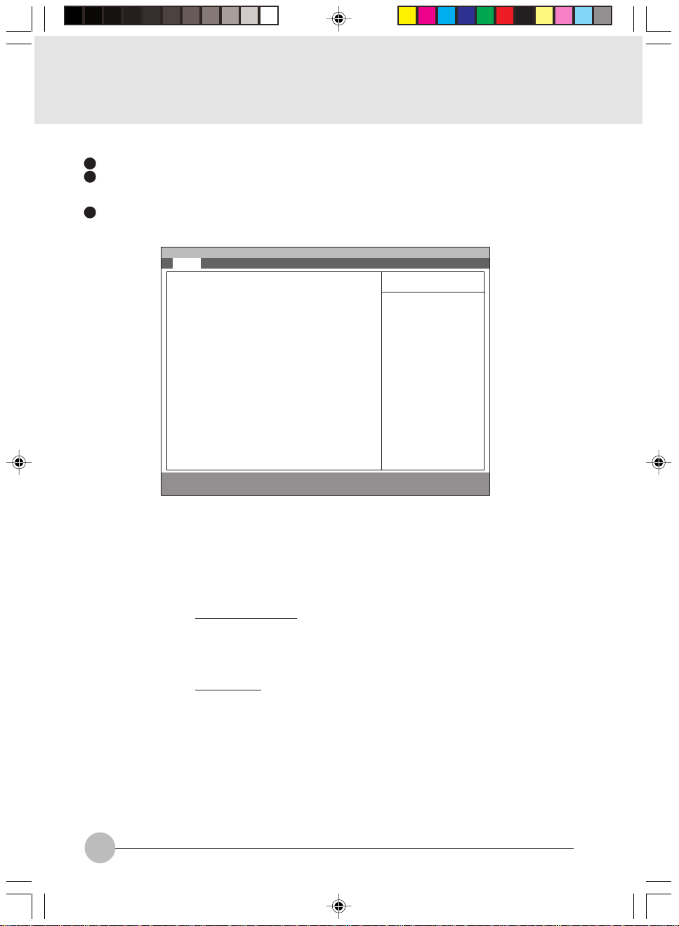
1.1 Main Menu
PhoenixBIOS Setup Utility
[Hitachi-DK23BA-15-(PM)]
[NEC CD-ROM Drive:282-(PS)]
Figure 1-1 Main menu
Note (Item Specific Help)
Adjust calendar clock.
<Tab>, <Shift-Tab>, or <Enter> selects field.
Adjust calendar date.
<Tab>, <Shift-Tab>, or <Enter> selects field.
Select Floppy Disk type. Note that 1.25 MB, 3
S
1/2” references a 1024 byte/sector Japanese
media format.
Configures ATA/A TAPI device.
Configures ATA/ATAPI device.
Select the display language for the BIOS.
Item Specific Help
<Tab>, <Shift-Tab>,
or <Enter> selects
field.
Setup Item
System Time
System Date
Floppy Disk A
Primary Master
Primary Slave
Language
Main Advanced Security Power Boot Info Exit
System Time: [12:34:56]
System Date: [01/02/2000]
Floppy Disk A: [1.44/1.25 MB 31/2”]
:Primary Master:
:Primary Slave:
Language: [English (US)]
F1 Help ↑↓ Select Item -/Space Change Value F9 Setup Defaults
ESCExit ←→ Select Menu Enter Select :Sub-MenuF10Save and Exit
Selections
00:00:00 to 23:59:59
01/01/1981 to
12/31/2099
Disabled
1.44/1.25 MB 3 1/2”
English (US)
xxxxxx (JP)
2
Elli2 BIOS_1-9 06/10/2000, 14:292
Table 1-1 Main menu options
Page 3

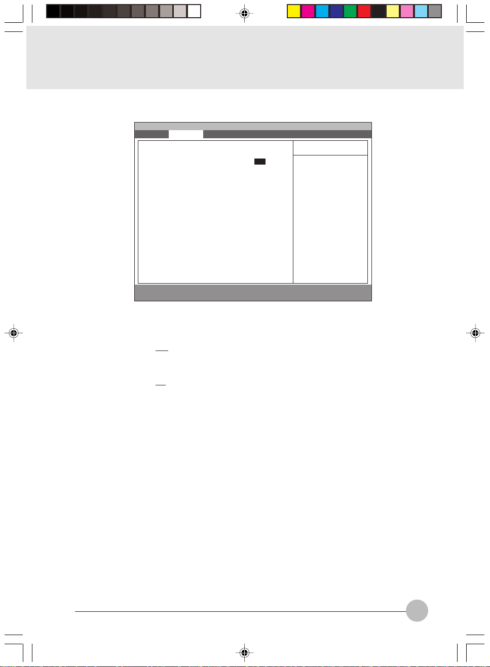
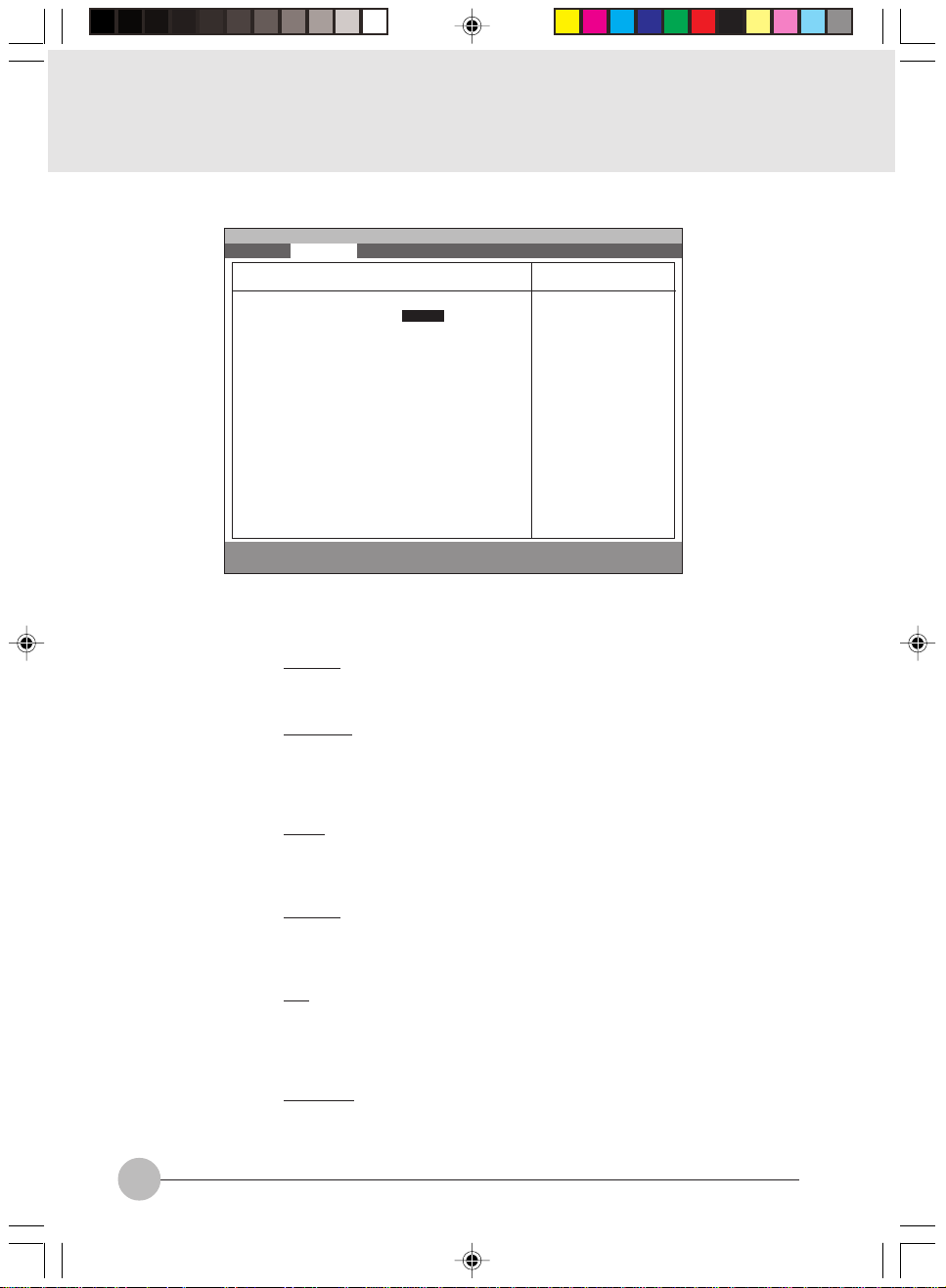
1.1.1 Main - Primary Master, Secondary Master Menu
Main Advanced Security Power Boot Info Exit
Primary Master [Hitachi-DK23BA-15-(PM)]
PhoenixBIOS Setup Utility
Item Specific Help
Setup Item
Type
Maximum Capacity
Type: [AUTO]
Maximum Capacity: XX MB
Multi-Sector Transfers: [16 Sectors]
LBA Mode Control: [Enabled]
PIO Transfer Mode: [Fast PIO 4]
DMA Transfer Mode: [Ultra DMA 2]
F1 Help ↑↓ Select Item -/Space Change Value F9 Setup Defaults
ESCExit ←→ Select Menu Enter Select :Sub-MenuF10Save and Exit
Select ATA/ATAPI
drive installed
here.
[AUTO]
The BIOS auto-types
the drive on boot
time.
Except [Auto]
You enter parameters
of the drive.
[None]
The drive is
disabled.
Figure 1-2 Main - Primary/Secondary Master Menu
Selections
Auto
None
CD-ROM
ATAPI Removable
Hardisk
Note (Item Specific Help)
Select ATA/ATAPI device type. If ‘Auto’ is
selected, the type is automatically identified
at POST by the BIOS. It does not carry out
Cylinder/Head/Sector display in the case of
over 8.4GB-HDD when Auto mode.
Hard Disk = you enter parameters of harddisk drive installed at this connection.
CD-ROM = a CD-ROM drive is installed here.
ATAPI Removable = removable disk drive is
installed here.
If ‘None’ is selected, all of the following setup
items do not appear. When ‘User’ is selected,
you can specify Cylinders, Head and Sectors.
Auto=autotypes ATA/ATAPI drive installed
here.
xxxx MB
Multi-Sector
Transfers
Disabled
2 Sectors
4 Sectors
8 Sectors
16 Sectors
MAX 32 Sectors
MAX 64 Sectors
MAX 128 Sectors
Elli2 BIOS_1-9 28/09/2000, 16:273
This option can not be changed when ‘Auto’
S
is selected.
Specify the number of sectors per block for
multiple sector transfer . ‘MAX’ refers to the siz e
the disk returns when required.
3
Page 4

Setup Item
LBA Mode Control
PIO T ransf er Mode
DMA T ransf er Mode
Selections
Disabled
Enabled
Standard
Fast PIO 1
Fast PIO 2
Fast PIO 3
Fast PIO 4
Disabled
Multiword DMA 1
Multiword DMA 2
Ultra DMA 0
Ultra DMA 1
Ultra DMA 2
Table 1-2 Main - Primary/Secondary Master menu options
Note (Item Specific Help)
This option can not be changed when ‘Auto’
S
is selected.
Enabling LBA causes Logical Block
Addressing to be used in place of Cylinders,
Heads & Sectors.
This option can not be changed when ‘Auto’
S
is selected. Multi-word DMA is automatically
set to mode 1 for ‘Fast PIO 1’, ‘Fast PIO 2’,
‘Fast PIO 3’ and set to mode 2 for ‘Fast PIO
4’.
Selects the method of moving data to/from
the drive. Autotype the drive to select the
optimum transfer mode.
You can not change this option when ‘A uto’ is
S
selected.
Selects the Ultra DMA mode used for moving
data to/from the drive. Autotype the drive to
select the optimum transfer mode.
4
Elli2 BIOS_1-9 28/09/2000, 16:274
Page 5
1.2 Advanced Menu
Setup Item
Plug & Play O/S
Protected Device
Configurations
Serial/Parallel Port
Configuration
Main Advanced Security Power Boot Info Exit
Plug & Play O/S [Yes]
Protected Device Configurations [No]
:Serial/Parallel Port Configurations
:Keyboard/Mouse Features
:Video Features
:Internal Device Configurations
:PCI Configuration
:CPU Features
:USB Features
:Event Logging
F1 Help ↑↓ Select Item -/Space Change Value F9 Setup Defaults
ESCExit ←→ Select Menu Enter Select :Sub-MenuF10Save and Exit
PhoenixBIOS Setup Utility
Item Specific Help
[No]
The BIOS configures
also non-boot
devices. Select if
you are using a nonPlug & Play OS or a
non-ACPI OS.
[Yes]
The BIOS configures
only boot devices.
Figure 1-3 Advanced menu
Selections
No
Yes
Note (Item Specific Help)
Select ‘Yes’ if you are using a Plug & Play
S
capable operating system.
Select ‘No’ if you need the BIOS to configure
non-boot devices.
No
Yes
‘Yes’ prevents a Plug and Play Operating
S
System from changing system settings.
Configures serial port and parallel ports.
Keyboard/Mouse
Features
Video Features
Internal Device
Configurations
CPU Features
USB Features
Event Logging
Elli2 BIOS_1-9 28/09/2000, 16:275
Setup keyboard/mouse features.
Setup display and video features.
Configures other internal devices.
Configures CPU features.
Configures USB features.
Configure Event logging.
Table 1-3 Advanced menu options
5
Page 6
1.2.1 Advanced - Serial/Parallel Port Configuration Menu
Main Advanced Security Power Boot Info Exit
Serial/Parallel Port Configuration
PhoenixBIOS Setup Utility
Item Specific Help
Setup Item
Serial port A
I/O address
Interrupt
Infrared port
Serial port A: [Enable]
I/O address: [3F8-3FF]
Interrupt: [IRQ 4]
Infrared port: [Enabled]
Mode: [FIR]
I/O address: [2E8-2EF]
Interrupt: [IRQ 3]
I/O address: [118-11F]
DMA channel: [DMA 3]
Parallel port: [Enabled]
Mode: [Bi-directional]
I/O address: [378-37F]
Interrupt: [IRQ 7]
F1 Help ↑↓ Select Item -/Space Change Value F9 Setup Defaults
ESCExit ←→ Select Menu Enter Select :Sub-MenuF10Save and Exit
[Disabled]
The port is
disabled.
[Enabled]
The port is enabled
with user configuration
[Auto]
The port is
configured depending
on ‘Plug & Play OS’
setting.
Figure 1-4 Advanced - Serial/Parallel Port Configuration menu
Selections
Disabled
Enabled
Auto
Note (Item Specific Help)
S
Configure serial port A using options:
[Disabled] No configuration
[Enabled] User configuration
[Auto] BIOS or OS chooses configuration.
3F8 - 3FF
2F8 - 2FF
3E8 - 3EF
S
This option is available when Serial port A is
‘Enabled’.
Set the base I/O address for serial port A.
2E8 - 2EF
IRQ 3
IRQ 4
IRQ 10
S
This option is available when Serial port A is
‘Enabled’.
Set the interrupt for serial port A.
IRQ 11
Disabled
Enabled
Auto
S
Configure serial port B using options:
[Disabled] No configuration
[Enabled] User configuration
[Auto] BIOS or OS chooses configuration
Mode
IrDA
FIR
I/O address
3F8 - 3FF
2F8 - 2FF
3E8 - 3EF
2E8 - 2EF
6
Elli2 BIOS_1-9 28/09/2000, 16:276
S
This option is available when Serial port B is
‘Enabled’.
Set the mode for serial port B.
S
This option is available when Serial port B is
‘Enabled’.
Set the base I/O address for serial port B.
Page 7

Setup Item
Interrupt
I/O address
DMA channel
Selections
IRQ 3
IRQ 4
IRQ 10
IRQ 11
100 - 107
108 - 10F
110 - 117
118 - 11F
DMA 1
DMA 3
Note (Item Specific Help)
S
This option is available when Serial port B is
‘Enabled’.
Set the interrupt for serial port B.
S
This option is available when Mode f or Serial
port B is set to ‘FIR’.
Set the base I/O address for the FIR of serial
port B.
S
This option is available when Mode f or Serial
port B is set to ‘FIR’.
Set the DMA channel for the FIR of serial port
B.
Parallel port
Mode
I/O address
Interrupt
Disabled
Enabled
Auto
Output only
Bi-directional
ECP
378 - 37F
278 - 27F
3BC - 3EF
IRQ 5
IRQ 7
Table 1-4 Advanced - Serial/Parallel Port Configuration menu options
S
Configure parallel port using options:
[Disabled] No configuration
[Enabled] User configuration
[Auto] BIOS or OS chooses configuration
S
This option is available when Parallel port is
‘Enabled’. When you change this mode to
‘ECP’, ‘DMA 1’ is selected by default.
Set the mode for the parallel port.
S
This option is available when Parallel port is
‘Enabled’.
Set the base I/O address for the parallel port.
S
This option is available when Serial port B is
‘Enabled’.
Set the interrupt for the parallel port.
Elli2 BIOS_1-9 28/09/2000, 16:277
7
Page 8

1.2.2 Advanced - Keyboard/Mouse Features Menu
g
Main Advanced Security Power Boot Info Exit
Keyboard/Mouse Features
PhoenixBIOS Setup Utility
Item Specific Help
Numlock: [Auto]
Hot plug: [Enabled]
Internal Pointing Device: [Auto Disabled]
Infrared Mouse: [Disabled]
F1 Help ↑↓ Select Item -/Space Change Value F9 Setup Defaults
ESCExit ←→ Select Menu Enter Select :Sub-Menu F10Save and Exit
Figure 1-5 Advanced - Keyboard/Mouse Features menu
metIputeSsnoitceleS)pleHcificepSmetI(etoN
kcolmuNotuA
nO
ffO
gulPtoHdelbasiD
delbanE
eciveD
gnitnioPlanretnI
delbasiDotuA
gnitteSlaunaM
delbanEsyawlA
delbasiDsyawlA
S.kcolmuNrofetatsno-rewoPstceleS
S.snoitcnufgulPtoHesuoM/draobyeK
Seht,detcelessidelbasiD/delbanEsyawlAfI
Selects power-on
state for Numlock.
.delbane
.yektoHyb
/delbanesyawlasiecivedgnitnioplanretni
eht,detcelessidelbasiDotuAfI.delbasid
nanehwdelbasidsiecivedgnitnioplanretni
htiwdetcennocsiecivedgnitnioplanretxe
ecivedgnitnioponfi,revewoH.trop2/SPeht
siecivedgnitnioplanretnieht,detcennocsi
lanretnieht,detcelessignitteslaunamfI
delbasidrodelbaneebnacecivedgnitniop
esuoMderarfnIdelbasiD
delbanE
Table 1-5 Advanced - Keyboard/Mouse Features menu options
8
Elli2 BIOS_1-9 28/09/2000, 16:278
Slanretxe2/SP,delbanesiesuoMderarfnIfI
esuoT.delbasideblliwecivedgnitniop
,ylsuoenatlumisecivedgnitnioplanretni
lanretnIni”delbanEsyawlA“tcelesesaelp
nitnioP
.unemeciveD
Page 9

1.2.3 Advanced - Video Features Menu
Main Advanced Security Power Boot Info Exit
PhoenixBIOS Setup Utility
Video Features
Item Specific Help
Setup Item
Display
Compensation
TV Output
TV Standard
Display: [Internal Flat-Panel]
Compensation: [Disabled]
TV Output: [Disabled]
TV Standard: [NTSC]
F1 Help ↑↓ Select Item -/Space Change Value F9 Setup Defaults
ESCExit ←→ Select Menu Enter Select :Sub-MenuF10Save and Exit
Select display
terminal.
Enabled TV output
Select TV Standard
Figure 1-6 Advanced - Video Features menu
Selections
Flat-Panel
Note (Item Specific Help)
Select display terminal.
CRT
Simultaneous
Disabled
Select compensation.
Enabled
Disabled
Enabled TV output.
Enabled
NTSC
Select TV standard.
PAL
Elli2 BIOS_1-9 28/09/2000, 16:279
Table 1-6 Advanced - Video Features menu
9
Page 10

1.2.4 Advanced - Internal Device Configurations
Main Advanced Security Power Boot Info Exit
Internal Device Configuration
PhoenixBIOS Setup Utility
Item Specific Help
Floppy Disk Controller: [Enabled]
IDE Controller: [Enabled]
F1 Help ↑↓ Select Item -/Space Change Value F9 Setup Defaults
ESCExit ←→ Select Menu Enter Select :Sub-Menu F10Save and Exit
[Disabled]
Floppy disk drive is
disabled
[Enabled]
Floppy disk drive is
enabled.
Figure 1-7 Advanced - Internal Device Configuration menu
metIputeSsnoitceleS)pleHcificepSmetI(etoN
ksiDyppolF
rellortnoC
delbanE
delbasiD
rellortnoCEDIdelbanE
delbasiD
Table 1-7 Advanced - Internal Device Configuration menu options
.rellortnocksidyppolfehtselbanE
.tropEDIehtselbanE
10
Elli2 BIOS_10-20 28/09/2000, 16:2710
Page 11

1.2.5 Advanced - PCI Configuration Menu
Main Advanced Security Power Boot Info Exit
:IRQ Reservation
F1 Help ↑↓ Select Item -/Space Change Value F9 Setup Defaults
ESCExit ←→ Select Menu Enter Select :Sub-MenuF10Save and Exit
PhoenixBIOS Setup Utility
PCI Configuration
Item Specific Help
Reserve specific
IRQs for use by
legacy ISA devices.
Figure 1-8 Advanced - PCI Configuration menu
metIputeSsnoitceleS)pleHcificepSmetI(etoN
noitavreseRQRI ASIycagelybesurofsQRIcificepsevreseR
.secived
Table 1-8 Advanced - PCI Configuration - IRQ Reservation menu options
Elli2 BIOS_10-20 28/09/2000, 16:2711
11
Page 12

1.2.5.1 Advanced - PCI Configuration - IRQ Reservation Menu
Setup Item
IRQ 3
IRQ 4
IRQ 5
IRQ 7
IRQ 9
IRQ 10
IRQ 11
IRQ 15
12
Main Advanced Security Power Boot Info Exit
IRQ 3: [Available]
IRQ 4: [Available]
IRQ 5: [Available]
IRQ 7: [Available]
IRQ 9: [Available]
IRQ 10: [Available]
IRQ 11: [Available]
IRQ 15: [Available]
F1 Help ↑↓ Select Item -/Space Change Value F9 Setup Defaults
ESCExit ←→ Select Menu Enter Select :Sub-MenuF10Save and Exit
PhoenixBIOS Setup Utility
IRQ Reservation
Item Specific Help
Reserve the
specified IRQ for
use by legacy ISA
devices.
Figure 1-9 Advanced - PCI Configuration - IRQ Reservation menu
Selections
Available
Reserved
Note (Item Specific Help)
If [Reserved] is selected, the BIOS reserves IRQ 3
S
for use by legacy ISA devices and does not use it for
embedded PCI or ISA devices. IRQ 3 is removed from
the IRQ bitmap in the PCI IRQ routing table.
Reserve the specified IRQ for use by legacy ISA
devices.
Available
Reserved
Reserves IRQ 4.
S
Reserve the specified IRQ for use by legacy ISA
devices.
Available
Reserved
Reserves IRQ 5.
S
Reserve the specified IRQ for use by legacy ISA
devices.
Available
Reserved
Reserves IRQ 7.
S
Reserve the specified IRQ for use by legacy ISA
devices.
Available
Reserved
Reserves IRQ 9.
S
Reserve the specified IRQ for use by legacy ISA
devices.
Available
Reserved
Reserves IRQ 10.
S
Reserve the specified IRQ for use by legacy ISA
devices.
Available
Reserved
Reserves IRQ 11.
S
Reserve the specified IRQ for use by legacy ISA
devices.
Available
Reserved
Reserves IRQ 15.
S
Reserve the specified IRQ for use by legacy ISA
devices.
Table 1-9 Advanced - PCI Configuration - IRQ Reservation menu options
Elli2 BIOS_10-20 28/09/2000, 16:2712
Page 13

1.2.5.2 Advanced - CPU Features
Main Advanced Security Power Boot Info Exit
Processor Serial Number : [Disabled]
Intel® Speedstep™ Technology : [Auto]
F1 Help ↑↓ Select Item -/Space Change Value F9 Setup Defaults
ESCExit ←→ Select Menu Enter Select :Sub-MenuF10Save and Exit
PhoenixBIOS Setup Utility
CPU Features
Figure 1-9a Advanced - CPU Features
metIputeSsnoitceleS)pleHcificepSmetI(etoN
laireSrossecorP
]delbasiD[
rebmuN
®
letnI
™petsdeepS
ygolonhceT
otuA
troP.xaM
tpOttaB
delbasiD
Item Specific Help
Configures Processor
Serial Number
feature of Pentium
III processor
[Disabled]
Processor Serial
Number feature is
disabled
[Enabled]
Processor Serial
Number feature is
enabled
rossecorpIIImuitnePfo
egnahcecruos
]troP.xaM[
erutaefrebmuNlaireSrossecorPserugifnoC
rewopnopudesabdegnahcsideepSUPC
dezimixamsideepsUPC
Elli2 BIOS_10-20 28/09/2000, 16:2713
]tpOttaB[
yrettabrofdezimitposideepsUPC
.noitarepo
]delbasiD[
dezimitpoyrettabehtotdexifsideepsUPC
.deeps
13
Page 14

1.2.6 Advanced - USB Features
Main Advanced Security Power Boot Info Exit
USB Floppy Disk: [Disabled]
F1 Help ↑↓ Select Item -/Space Change Value F9 Setup Defaults
ESCExit ←→ Select Menu Enter Select :Sub-Menu F10Save and Exit
PhoenixBIOS Setup Utility
USB Features
Figure 1-10 Advanced - USB Features
metIputeSsnoitceleS)pleHcificepSmetI(etoN
delbasiD
delbanE
Table 1-10 Advanced - USB Features
Item Specific Help
[Disabled]
Legacy Floppy
Emulation is
disabled.
[Enabled]
legacy Floppy
Emulation is enabled
and USB floppy is
available without USB
aware OS.
SO
.delbasidsinoitalumEyppolFycageL
dnadelbanesinoitalumEyppolFycageL
erawaBSUtuohtiwdelbaliavasiyppolfBSU
14
Elli2 BIOS_10-20 28/09/2000, 16:2714
Page 15

1.2.7 Advanced - Event Logging Menu
F1 Help ↑↓ Select Item -/Space Change Value F9 Setup Defaults
ESCExit ←→ Select Menu Enter Select :Sub-MenuF10Save and Exit
Setup Item
Event log capacity
Event log validity
View event log
Event Logging
System Boot Event
Clear all event logs
Mark Events as Read
Main Advanced Security Power Boot Info Exit
Event log capacity: Space Available
Event log validity: Valid
View Event Log: [Enter]
Event Logging: [Enabled]
System Boot Event: [Disabled]
Clear all DMI event logs: [No]
Mark Events As Read: [Enter]
PhoenixBIOS Setup Utility
Event Logging
Item Specific Help
Press <Enter> key to
view the contents of
the event log.
Figure 1-11 Advanced - Event Logging menu
Selections
Note (Item Specific Help)
Display event log capacity.
Display event log validity.
Enter
Disabled
Display event log.
S
Enables event logging.
S
Enabled
Disabled
Enabled
No
Yes
[Disabled] The event is ignored.
S
[Enabled] The event may be logged.
[No] Event logs will not be cleared at the next
boot.
[Yes] All event logs will be cleared at the next
boot.The value is reset to [No] after clearing.
[Enter]
Press <Enter> key to mark all events currently
in the event log as read. Marked events will
not be displayed from next “View Event Log”
Table 1-11 Advanced - Event Logging menu options
Elli2 BIOS_10-20 28/09/2000, 16:2715
15
Page 16

1.3 Security Menu
F1 Help ↑↓ Select Item -/Space Change Value F9 Setup Defaults
ESCExit ←→ Select Menu Enter Select :Sub-MenuF10Save and Exit
metIputeSsnoitceleS)pleHcificepSmetI(etoN
rosivrepuS
sIdrowssaP
sIdrowssaPresU .drowssapresUfognittesehtyalpsiD
Main Advanced Security Power Boot Info Exit
Supervisor Password Is: Clear
User Password Is: Clear
Set Supervisor Password [Enter]
Set User Password [Enter]
Minimum User Password Length [0]
Password on boot: [Disabled]
Password on Resume: [Disabled]
Boot from Removable Media [All]
Floppy Disk Access: [All]
:Hard Disk Security
:Owner Information
Hard Disk Boot Sector [Normal]
PhoenixBIOS Setup Utility
Item Specific Help
Press <Enter> key to
set Supervisor
Password to enable
any password
features.
Then password entry
is required to enter
BIOS Setup.
Figure 1-12 Security menu
.drowssaprosivrepuSfognittesehtyalpsiD
rosivrepuSteS
drowssaP
drowssaPresUteS rosivrepuSretfatesebnacdrowssapresU
resUmuminiM
htgneLdrowssaP
delbasiD
delbanE
toobnodrowssaPdelbasiD
delbanE
nodrowssaP
emuseR
morFtooB
delbasiD
delbanE
llA
aideMelbavomeR
16
Elli2 BIOS_10-20 28/09/2000, 16:2716
SehtotsseccaslortnocdrowssaProsivrepuS
.ytilituputes
.tessidrowssap
tametsysehtotsseccaslortnocdrowssaPresU
.toob
S.htgneldrowssapresuehtsteS
SOIBeht,’delbanE‘sitoobnodrowssaPnehW
.toobSOnodrowssapaseriuqer
.toobnoyrtnedrowssapselbanE
nopudrowssapaeriuqeroterutaefsihtelbanE
.edoMksiDoTevaSrodnepsuSmorfemuseR
no-rewopruoyotlacitnedisidrowssapsihT
.drowssap
drowssaprosivrepuShtiwtesebnacmetisihT
rosivrepuS
si’ylnOrosivrepuS‘nehW.levelytiruces
htiwelbaliavatonsiaidemelbavomer,detceles
putoobslortnoC.levelytirucesdrowssapresU
.aidemelbavomermorf
Page 17

metIputeSsnoitceleS)pleHcificepSmetI(etoN
sseccaksidyppolFllA
ylnOrosivrepuS
ytirucesksiddraHdelbasiD
delbanE
noitamrofnIrenwO .noitamrofnis'renwoyalpsiD
rotceS
tooBksiDdraH
lamroN
detcetorPetirW
Table 1-12 Security menu options
rosivrepuShtiwtesebnacmetisihT
’rosivrepuS'nehW.levelytirucesdrowssap
tonsiaidemelbavomer,detcelessiylno
.levelytirucesdrowssapresUhtiwelbaliava
.sevirdyppolfotsseccalortnoC
rosivrepuShtiwtesebnacmetisihT
si’delbanE'nehW.levelytirucesdrowssap
eraksiddrahehtfoatadeht,detceles
foerutaefkcoldrowssapehthtiwdetcetorp
ehtnoatadynadaertonnacuoY.evirdeht
metsysemasehtnidellatsnitonsitifievird
.drowssapehthtiwdekcolsitisa
.ytirucesksiddexifselbanE
royllamronnettirwebotrotcestoobswollA
.detcetorp-etirw
1.3.1 Set Supervisor Password
Supervisor Password Is: Clear
Set Supervisor Password
Enter New Password [ ]
Confirm New Password [ ]
Supervisor Password Is: Set
Set Supervisor Password
Enter Current Password [ ]
Enter New Password [ ]
Confirm New Password [ ]
1.3.2 Set User Password
User Password Is: Clear
Set User Password
Enter New Password [ ]
Confirm New Password [ ]
User Password Is: Set
Set User Password
Enter Current Password [ ]
Enter New Password [ ]
Confirm New Password [ ]
17
Elli2 BIOS_10-20 28/09/2000, 16:2717
Page 18

1.4 Power Menu
Main Advanced Security Power Boot Info Exit
Power Savings: [Customized]
Hard Disk Timeout: [Off]
Display Timeout: [Off]
Standby Timeout: [4 Minutes]
Auto Suspend Timeout: [15 Minutes]
Suspend Mode: [Suspend]
Auto Save To Disk: [Off]
Resume On Modem Ring: [Off]
Resume On Time: [Off]
Resume Time: [00:00:00]
:Advanced Features
F1 Help ↑↓ Select Item -/Space Change Value F9 Setup Defaults
ESCExit ←→ Select Menu Enter Select :Sub-MenuF10Save and Exit
PhoenixBIOS Setup Utility
Item Specific Help
Select Power
Management Mode.
Choosing modes
changes system power
management settings.
Maximum Power Savings
conserves the
greatest amount of
system power while
Maximum Performance
conserves power but
allows greatest
system performance.
To alter these
settings, choose
Customize. To turn
off power management,
choose Disable.
Figure 1-13 Power menu
Setup Item
Power Savings
Hard Disk Timeout
Display Timeout
18
Selections
Disabled
Customized
Maximum Power savings
Maximum Performance
Off
30 seconds
1 Minute
2 Minutes
4 Minutes
6 Minutes
8 Minutes
10 Minutes
15 Minutes
20 Minutes
Off
2 Minutes
4 Minutes
6 Minutes
8 Minutes
10 Minutes
15 Minutes
20 Minutes
Note (Item Specific Help)
Select Power Management Mode. Choosing
modes changes system power management
settings. Maximum P ow er Savings conserves
the greatest amount of system power while
Maximum Performance conserves power b ut
allows greatest system performance. To alter
these settings, choose Customized. To turn
off power management, choose Disabled.
Amount of time the hard disk needs to be
inactive before it is turned off.
Amount of time the user input devices need
to be inactive before the screen is turned off.
Elli2 BIOS_10-20 28/09/2000, 16:2718
Page 19

Setup Item
Standby Timeout
Selections
Off
1 Minute
2 Minutes
4 Minutes
6 Minutes
8 Minutes
12 Minutes
16 Minutes
Note (Item Specific Help)
Amount of time the system needs to be
inactive before entering the Standby Mode.
Standby Mode turns off various devices in the
system, including the screen, until you start
using the computer again.
Auto Suspend
Timeout
Suspend Mode
Auto Save To Disk
Resume On Modem
Ring
Resume On Time
Resume Time
Advanced Features
Off
5 Minutes
10 Minutes
15 Minutes
20 Minutes
30 Minutes
40 Minutes
60 Minutes
Suspend
Save To Disk
Off
After 1 Hour
Off
On
Off
On
00:00:00 to 23:59:59
Table 1-13 Power menu options
Amount of time the system needs to be
inactive before entering the Suspend Mode.
Select the type of Suspend Mode. If you
choose Save To Disk the system will sav e its
state to disk and power off. If you choose
Suspend the system will save its state but
remain in a low power mode. If you choose
Suspend then you also have the option of
choosing Auto Save To Disk.
Turn on or off the Auto Save To Disk f eature.
When Auto Save To Disk is turned on, the
system will save its state to disk and then
power off after being in Suspend mode for a
period of time.
Turning this feature on will wake the system
up when an incoming call is detected on your
modem in Suspend Mode.
Turning this feature on will wake the system
up at ‘Resume Time’ from Suspend Mode.
Specify the time when the system is to wake
up. <Tab>, <Shift-Tab>, or <Enter> selects
field.
Allows editing of advanced power
management features.
Power Saving Mode Hard Disk Video Standby Auto Suspend
Disabled Off Off Off Off
Customized Off Off 4 Minutes 15 Minutes
Maximum Power Savings 30 Seconds 2 Minutes 1 Minute 5 Minutes
Maximum Performance Off Off Off 15 Minutes
Table 1-13a Preset values for each Power Saving Modes
Elli2 BIOS_10-20 28/09/2000, 16:2719
19
Page 20

1.4.1 Power - Advanced Features Modes
Main Advanced Security Power Boot Info Exit
PhoenixBIOS Setup Utility
Advanced Features
Item Specific Help
F1 Help ↑↓ Select Item -/Space Change Value F9 Setup Defaults
ESCExit ←→ Select Menu Enter Select :Sub-MenuF10Save and Exit
Setup Item
SUS/RES Switch
Lid Closure Suspend
Lid Open Resume
Serial Mouse Activity
Suspend/Resume Switch: [Enabled]
Lid Closure Suspend: [On]
Lid Open Resume: [On]
Serial Mouse Activity: [Disabled]
Configures the
Suspend/Resume
switch.
Figure 1-14 Power - Advance Features menu
Selections
Disabled
Note (Item Specific Help)
Set the SUS/RES Switch.
Enabled
Off
Set the Lid Closure Suspend.
On
Off
Set the Lid Open Resumes.
On
Disabled
Enabled
Turning this feature on will wake the video up
from standby mode when external serial
connector activity is detected.
Table 1-14 Power - Advanced Features menu options
20
Elli2 BIOS_10-20 28/09/2000, 16:2720
Page 21

1.5 Boot Menu
Main Advanced Security Power Boot Info Exit
QuickBoot: [Enabled]
Boot-time Diagnostic Screen: [Disabled]
:Boot Device Priority
F1 Help ↑↓ Select Item -/Space Change Value F9 Setup Defaults
ESCExit ←→ Select Menu Enter Select :Sub-Menu F10Save and Exit
PhoenixBIOS Setup Utility
Item Specific Help
[Disabled]
All diagnostic test
will be done.
[Enabled]
Some diagnostic tests
may be skipped while
booting to speed up.
[Auto]
Diagnostic tests will
be automatically
skipped or done
according to the
order of the ACPI OS.
Figure 1-15 Boot menu
Setup Item
QuickBoot
Boot-time Diagnostic
Screen
Boot Device Priority
Selections
Disabled
Enabled
Auto
Disabled
Enabled
Table 1-15 Boot menu options
Note (Item Specific Help)
Allows the system to skip certain tests while
S
booting. This will decrease the time needed
to boot the system.
Display the diagnostic screen during boot.
S
Select the search order for the types of boot
devices.
21
Elli2 BIOS_21-28 28/09/2000, 16:2821
Page 22

1.5.1 Boot - Boot Device Priority Menu
Main Advanced Security Power Boot Info Exit
Floppy Disk Drive
+Hard Disk Drive
ATAPI CD-ROM Drive
F1 Help ↑↓ Select Item -/Space Change Value F9 Setup Defaults
ESCExit ←→ Select Menu Enter Select :Sub-MenuF10Save and Exit
PhoenixBIOS Setup Utility
Boot Device Priority
Figure 1-16 Boot - Boot Device Priority menu
Setup Item
Bootable devices available are listed. The
following devices will appear depending on
the hardware configuration.
[Diskette Drive]
[Hard Drive]
[ATAPI CD-ROM Drive]
Table 1-16 Boot - Boot menu DevicePriority options
Item Specific Help
The top device has
the highest priority.
<Enter> expands or
collapses devices
with a + or -.
<Ctrl+Enter> expands
all.
<↑> or <↓> select a
device.
<+>/<Space> or <->
move the device up or
down.
<Shift+D> enabled or
disabled a device.
Note (Item Specific Help)
<Enter> expands or collapses devices with
a + or -.
<Ctrl+Enter> expands all.
<↑> or <↓> select a device.
<+>/<Space> or <-> move the device up or
down.
<Shift+D> enabled or disabled a device.
1.5.1.1 Boot Menu at POST
The following pop up menu will appear when you hit the F12 k e y during POST. The device list in this
pop up menu are same as the list in the Boot Device Priority menu.
Boot Menu
1. Floppy Disk Drive
2. Hard Drive Drive
3. ATAPI CD-ROM Drive
<Enter Setup>
22
Elli2 BIOS_21-28 28/09/2000, 16:2822
Page 23

1.6 Info Menu
Main Advanced Security Power Boot Info Exit
BIOS Version: 1.xx
BIOS Date: 01/02/2000
BIOS Area: E400h - FFFh
CPU Type:
CPU Speed: 700MHz
L1 Cache: 32KB
L2 Cache: 256KB
Total Memory: 128MB
On Board: 128MB SDRAM
Memory Slot: None
F1 Help ↑↓ Select Item -/Space Change Value F9 Setup Defaults
ESCExit ←→ Select Menu Enter Select :Sub-Menu F10Save and Exit
PhoenixBIOS Setup Utility
Item Specific Help
Pentium® III processor
Figure 1-17 Info menu
Information Item
BIOS Version
BIOS Date
BIOS Area
CPU Type
CPU Speed
L1 Cache
L2 Cache
Total Memory
On Board
Memory Slot
Values
n.nn
MM/DD/YYYY
xxxxh – FFFFh
Pentium® III processor
700MHz
32 KB
256KB
128 MB to 256 MB
128 MB SDRAM
None
Table 1-17 Info menu items
Note
This area can not be used as UMB.
23
Elli2 BIOS_21-28 28/09/2000, 16:2823
Page 24

1.7 Exit menu
Main Advanced Security Power Boot Info Exit
Exit Saving Changes
Exit Discarding Changes
Load Setup Defaults
Discard Changes
Save Changes
F1 Help ↑↓ Select Item -/Space Change Value F9 Setup Defaults
ESCExit ←→ Select Menu Enter Select :Sub-Menu F10Save and Exit
Setup Item
Exit Saving Changes
Exit Discarding Changes
Load Setup Defaults
PhoenixBIOS Setup Utility
Figure 1-18 Exit menu
Note (Item Specific Help)
Exit System Setup and save your changes to
CMOS.
Exit utility without saving Setup data to CMOS.
Load default values for all SETUP items.
Item Specific Help
Exit System Setup and
save your changes to
CMOS.
Discard Changes
Save Changes
24
Elli2 BIOS_21-28 28/09/2000, 16:2824
Load previous values from CMOS for all
SETUP items.
Save Setup Data to CMOS.
Table 1-18 Exit menu options
Page 25

1.7.1 Exit Saving Changes
1.7.4 Discard Changes
Setup Confirmation
Save configuration changes and exit now?
[Yes] [No]
1.7.2 Exit Discarding Changes
Setup Warning
Configuration has not been saved!
Save before exiting?
[Yes] [No]
1.7.3 Load Set up Defaults
Setup Confirmation
Load previous configuration now?
[Yes] [No]
Setup Confirmation
Save configuration changes now?
[Yes] [No]
1.7.5 Save Changes
Setup Confirmation
Load default configuration now?
[Yes] [No]
Elli2 BIOS_21-28 28/09/2000, 16:2825
25
Page 26

1.8 General Help
Main Advanced Security Power Boot Info Exit
Main
System Time: [12:34:56]
System Date: [06/02/1999]
Setup changes system behavior by modifying the BIOS
Legacy Diskette A: [1.44/1.25 MB 31/2”]
configuration. Selecting incorrect values may
cause system boot failure; load Setup Default values to
:Primary Master: [FUJITSU MHA2043AT]
recover.
:Secondary Master: [None]
:Secondary Master: [None]
<Up/Down> arrows select fields in current menu.
<Pgup/PgDn> moves to previous/next page on scrollable
System Memory: 640MB
menus.
Extended Memory: 31MB
<Home/End> moves to top/bottom item of current menu.
:Memory Cache
Within a field, <F5> or <–> selects next lower value and
Language: [English (US)]
<F6>, <+>, or <Space> selects next higher value.
F1 Help ↑↓ Select Item -/Space Change Value F9 Setup Defaults
ESCExit ←→ Select Menu Enter Select ➧Sub-Menu F10Save and Exit
PhoenixBIOS Setup Utility
General Help
[Continue]
Item Specific Help
<Tab>, <Shift-Tab or
or <Enter> selectld.
Figure 1-19 General Help
General Help
Setup changes system behavior by modifying the BIOS
configuration. Selecting incorrect values may
cause system boot failure; load Setup Default values to
recover.
<Up/Down> arrows select fields in current menu.
<PgUp/PgDn> moves to previous/next page on scrollable menus.
<Home/End> moves to top/bottom item of current menu.
:
Within a field, <F5> or <-> selects next lower value and
<F6>, <+>, or <Space> selects next higher value.
<Left/Right> arrows select menus on menu bar.
<Enter> displays more options for items marked with _.
<F9> loads factory installed Setup Default values.
<F10> saves current settings and exits Setup.
<Esc> or <Alt-X> exits Setup; in sub-menus, pressing these
keys returns to the previous menu.
<F1> or <Alt-H> displays General Help (this screen).
Table 1-19 Entire Text of General Help
26
Elli2 BIOS_21-28 28/09/2000, 16:2826
Page 27

2. POST Diagnostic Screen
PhoneixBIOS 4.0 Release 6.0
Copyright 1985-2000 Phoenix Technologies Ltd.
All Rights Reserved
Fujitsu LifeBook BIOS Version 1.xx
Copyright FUJITSU LIMITED 1997-2000.
CPU = Intel® Mobile Pentium® III processor 700mhz
128M System Memory Passed
256K Memory Cache Passed
System BIOS Shadowed
Mouse Initialized
Fixed disk 0: xxxxxxxxxxxx
ATAPI CD-ROM: xxxxxxxxxxxx
Press <F2> to enter SETUP. Press <F12> : Boot Menu
Figure 2-1 Typical Diagnostic Screen
Normal Messages
128M System Memory Passed
256K Memory Cache Passed
System BIOS shadowed
Mouse initialized
Press <F2> to enter SETUP
Entering SETUP ...
Table 2-1 Normal Messages in Diagnostic Screen
Error Messages
System Memory Failed at offset: xxxx
Failing Bits: zzzz
Extended Memory Failed at offset: xxxx
Failing Bits: zzzz zzzz
System cache error - Cache disabled
Keyboard controller error
Keyboard error
Diskette drive A error
Failure Fixed Disk n
Elli2 BIOS_21-28 28/09/2000, 16:2827
27
Page 28

Error Messages
System timer error
Real time clock error
System CMOS checksum bad - Default configuration used
Previous boot incomplete - Default configuration used
Press <F1> to resume,<F2> to Setup
Check date and time settings
Password locked: Fixed Disk n
No Save To Disk partition or file exists on Fixed Disk
- Save To Disk features is disabled.
Not enough Save To Disk partition or file exists on Fixed
Disk.
- Save To Disk feature is disabled.
Hard Disk Drive is not installed.
- Save To Disk feature is disabled.
Unknown Save To Disk error.
- Save To Disk feature is disabled.
Hard disk sector read function failed.
- Save To Disk feature is disabled.
Hard disk sector write function failed.
- Save To Disk feature is disabled.
Save To Disk partition or file corrupted.
- Save To Disk feature is disabled.
Fixed Disk is not installed. Cannot restore from disk.
To restore from disk : turn off system, install original
fixed disk and reboot.
Press <F1> to continue to boot without save to disk
data.
Fixed Disk has been changed. Cannot restore from disk.
To restore from disk : turn off system, install original fixed
disk and reboot.
Press <F1> to continue to boot without save to disk data.
Table 2-2 Error Messages in Diagnostic Screen
28
Elli2 BIOS_21-28 28/09/2000, 16:2828
 Loading...