

Page 1

Copyright
Fujitsu Limited has made every effort to ensure the accuracy and completeness of this document. However, as
ongoing development efforts are continually improving the capabilities of our products, we cannot guarantee the
accuracy of the contents of this document. We disclaim liability for errors, omissions, or future changes.
LifeBook is a trademark of Fujitsu Limited.
Microsoft, Windows, MS, MS-DOS , and Windows NT are registered trademarks of the Microsoft Corporation of the
United States in the United States and other countries.
Intel is a registered trademark of the Intel Corporation of the United States.
Celeron is a trademark of the Intel Corporation of the United States.
NeoMagic MagicMedia 256AV and NeoMagic MagicMedia 256AV+AC97 Driver (WDM) are trademarks of
NeoMagic™ Corporation.
Puma Technology, Intellisync is a trademark of Puma Technology Corporation of the United States.
Phoenix is a registered trademark of Phoenix Technologies Corporation of the United States.
K56flex is a trademark of Rockwell International Corporation and Lucent Technologies Corporation.
Magic Packet is a registered trademark of Advanced Micro Devices, Inc.
Other product names are trademarks or registered trademarks of their respective companies.
Other products are copyrighted by their companies.
Copyright© 1981-1999 Microsoft Corporation, All rights reserved.
Copyright© 1999 Phoenix Technologies, Ltd., All rights reserved.
All other products are trademarks or registered trademarks of their respective companies.
Explanations of the adjustments for the track pad cursor control are taken in part from the ALPS GlidePoint Driv er
User’s Guide, copyright by LCS/Telegraphics in 1996.
© Copyright 1999 Fujitsu Limited. All rights reserved. No part of this publication may be copied, reproduced, or
translated, without the prior written consent of Fujitsu Limited. No part of this publication may be stored or transmitted in any electronic form without the written consent of Fujitsu Limited.
DECLARATION OF CONFORMITY
according to FCC Part 15
Responsible Party Name : FPCA
Declares that product: Model : LifeBook C6530
Address : Fujitsu PC (Asia) Pte Ltd
200 Pandan Loop
#05-03, Pantech 21
The Computer Centre
Singapore 128388
Telephone : 65-776 0688
Complies with Part 15
of the FCC Rules.
This device complies with Part 15 of the FCC Rules. Operations are subject to the following two conditions:
(1) This device must not be allowed to cause harmful interference, (2) This device must accept any interference
received, including interference that may cause undesired operation.
Page 2

IMPORTANT SAFETY INSTRUCTIONS
1. Read these instructions carefully. Save these instructions for future reference.
2. Follow all warnings and instructions marked on the product.
3. Unplug this product from the wall outlet before cleaning. Do not use liquid cleaners or aerosol cleaners.
Use a damp cloth for cleaning.
4. Do not use this product near water.
5. Do not place this product on an unstable cart, stand, or table. The product may fall, causing serious
damage to the product.
6. Slots and openings in the cabinet and the back or bottom are provided for ventilation; to ensure reliab le
operation of the product and to protect it from overheating, these openings must not be blocked or
covered. The openings should never be blocked by placing the product on a bed, sofa, rug, or other
similar surface. This product should nev er be placed near or over a r adiator or heat register, or in a b uiltin installation unless proper ventilation is provided.
7. This product should be operated from the type of power indicated on the marking label. If you are not
sure of the type of power available, consult your dealer or local power company.
8. This product is equipped with a 3-wire grounding-type plug, a plug having a third (grounding) pin. This
will only plug into a grounding-type power outlet. This is a safety feature. If y ou are unable to insert the
plug into the outlet, contact your electrician to replace your obsolete outlet. Do not defeat the purpose
of the grounding-type plug.
9. Do not allow anything to rest on the power cord. Do not locate this product where persons will walk on
the cord.
10. If an extension cord is used with this product, make sure that the total ampere rating of the equipment
plugged into the extension cord does not exceed the extension cord ampere rating. Also, make sure
that the total rating of all products plugged into the wall outlet does not exceed 15 amperes.
11. Never push objects of any kind into this product through cabinet slots as they may touch dangerous
voltage points that could result in a fire or electric shock. Never spill liquid of any kind on the product.
12. Do not attempt to service this product yourself, as opening or removing covers may expose you to
dangerous voltage points or other risks. Refer all servicing to qualified service personnel.
13. Unplug this product from the wall outlet and refer servicing to qualified service personnel under the
following conditions:
a. When the power cord or plug is damaged or frayed.
b. If liquid has been spilled into the product.
c. If the product has been exposed to rain or water.
d. If the product does not operate normally when the operating instructions are followed. Adjust
only those controls that are covered by the operating instructions since improper adjustment of
other controls may result in damage and will often require extensive work by a qualified tech-
nician to restore the product to normal condition.
e. If the product has been dropped or the cabinet has been damaged.
f. If the product exhibits a distinct change in performance, indicating a need for service.
14. CAUTION. When replacing the battery, be sure to install it with the polarities in the correct posi-
tion. There is a danger of explosion if the battery is replaced with an incorrect type or is mistreated. Do not recharge, disassemb le or dispose of in fire. Replace only with the same or equiv alent type recommeded by the manufacturer . Dispose of the used battery accor ding to the manufacturer’s instructions.
15. Use only the proper type of power supply cord set (provided in your accessories box) for this unit. It
should be a detachable type: UL listed/CSA certified, BS1363,ASTA,SS145 cer tified, rated 10A 250V
minimum, VDE approved or its equivalent. Maximum length is 15 feet (4.6 meters).
Page 3
NOTATION IN THIS DOCUMENT
Warnings
This manual uses a variety of icons as visual marks so that you can use this computer safely and
correctly and avoid damage and danger to yourself and to others. These icons and their meanings are as follows. Please learn these icons before reading this manual. Learning these icons
will be useful for understanding this manual.
Icon Meaning
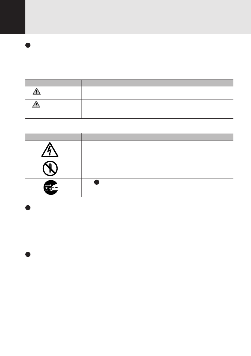
WARNING
CAUTION
The symbols below are used together with the icons above to indicate what type of danger or
damage is involved.
symbols Meaning
Incorrect handling ignoring this warning can cause a dangerous situation
that could result in death or severe injury.
Incorrect handling ignoring this warning can cause a dangerous situation
that could result in moderate or minor injury or could result in equipment
damage.
The symbol indicates a w arning or caution. The symbol indicates the
concrete nature of the warning. (The e xample on the left is a caution f or
electric shock.)
The circle and slash indicates prohibited behavior. The symbol inside
the circle indicates the concrete nature of the prohibition. (The example
on the left indicates that disassembly is prohibited.)
The indicates instructions that must be followed. The symbol inside
indicates the concrete nature of those instructions. (The e xample on the
left tells you to unplug the power plug from the socket.)
Key notation and operation methods
Explanations of key operations do not show all the characters on the keyboard. Instead they
indicate just the keys necessary to the explanation as follows.
Examples: [Ctrl] key, [Enter] key, [ → ] key
When multiple keys are to be pressed at the same time, this is indicated b y connecting them with
[+].
Examples: [Ctrl] + [F3] keys; [Shift] + [ ↑ ] key
Screen examples
The screens shown in this manual are examples. Please understand that the file names and
screens you use may be different.
Page 4

Notation in text
Here is what symbols in text mean.
Symbol Meaning
Critical Points
Critical Point Indicates a point necessary for correctly operating the
hardware or software.
Column Gives the meaning and brief explanation of a term.
Column
→ Indicates the page to see elsewhere in this manual.
Command input (key input)
Within the text of this manual, command input (giving commands to the computer by pressing
keys) is indicated as follows.
Example:
In the position indicated in the example above by the ↑, the space left between the characters
indicates that a space needs to be left in the entry by pressing the space bar (the long key with
nothing written on it at the center of the front of the keyboard). Commands are written in this
manual as lowercase latin letters, but uppercase letters may be used.
Product names
The following product names are abbreviated as follows in this manual.
“Microsoft® Windows® 98 operating system” is written as “Windows 98”.
“Microsoft® MS-DOS® operating system Version 6.2/V” is written as “MS-DOS”.
“Microsoft® Windows® operating system Version 3.1” is written as “Windows 3.1”.
“Microsoft® Windows NT® Workstation operating system Version 4.0” is written as
“Windows NT 4.0”.
“Microsoft® Windows NT® Workstation operating system Version 3.51” is written as
“Windows NT 3.51”.
“Windows NT 4.0” and “Windows NT 3.51” are both written as Windows NT.
“LifeBook” is written as “this computer” or “the computer main unit”.
dir c:
↑
Page 5

Configuration of this Manual
SECTION 1
This section explains basic operations and basic items for using this computer, including the
names of the parts and their functions, flat point operation methods, floppy disk unit handing, and
battery operation.
SECTION 2
This section explains installation of options for this computer.
SECTION 3
This section explains the BIOS setup program, which is necessary for setting the date and time
and power conservation mode. This section also explains how to set the password for protecting
data in this computer.
SECTION 4
This section explains what to do when trouble occurs with this computer and when messages are
displayed. Read this section as the necessity arises.
SECTION 1
SECTION 2SECTION 3
SECTION 4
Page 6

CONTENTS
SECTION 1
1. Names of the Parts and their Functions ........................2
Front .............................................................................................. 2
Left Side/Right Side .......................................................................4
Rear/Bottom .................................................................................. 6
Status Indicator LCD ..................................................................... 8
2. Keyboard.........................................................................10
Keyboard ..................................................................................... 10
Numeric Keypad Mode ................................................................ 10
Names of the Main Keys and their Functions.............................. 11
3. Turning on the Power.....................................................14
4. Turning off the Power.....................................................16
Turning Off the Power .................................................................. 16
5. Suspend/Resume Function ...........................................18
What Is the Suspend/Resume Function? .................................... 18
Precautions for Suspending......................................................... 18
Suspending.................................................................................. 19
Using the Resume Function ........................................................ 21
6. Battery .............................................................................22
Battery Charging.......................................................................... 22
Battery Operation ........................................................................ 23
Checking the Remaining Battery Charge .................................... 24
Low Battery State ........................................................................ 25
Replacing the Battery Pack ......................................................... 26
Bridge Battery .............................................................................. 28
Precautions for Battery Pack ....................................................... 29
7. Floppy Disk Drive ...........................................................30
Loading/Ejecting a Floppy Disk ................................................... 30
What is a Floppy Disk? ................................................................ 31
Precautions on Handling ............................................................. 32
8. CD-ROM Drive.................................................................33
CD-ROMs .................................................................................... 33
Loading/Ejecting a CD-ROM ....................................................... 34
Page 7

SECTION 1
SECTION 2
9. Internal Fax Modem........................................................36
What is a Fax Modem?................................................................ 36
Connection .................................................................................. 36
Modem Warnings......................................................................... 37
10.SPDIF Features ...............................................................38
How to use the SPDIF Output Connector?.................................. 38
1. Options............................................................................40
Options ........................................................................................ 40
2. PC Cards .........................................................................42
Precautions for PC Cards ............................................................ 42
Installing PC Cards ...................................................................... 43
Removing PC Cards .................................................................... 44
3. Expansion RAM Modules................................................46
Installing an Expansion RAM Module .......................................... 46
Removing an Expansion RAM Module ........................................ 49
4. Mouse ...............................................................................51
Connecting the Mouse................................................................. 51
Using the Mouse.......................................................................... 51
5. Numeric Keypad ..............................................................53
Connecting a Numeric Keypad .................................................... 53
6. Printer ...............................................................................54
Connecting a Printer .................................................................... 54
7. CRT Monitor.....................................................................56
Connecting an External CRT Monitor .......................................... 56
8. One-touch operation buttons .........................................58
Checking new arrival of E-mail .................................................... 60
9. Wireless Mouse................................................................61
Precautions on safety .................................................................. 61
Preparation and Preliminary knowledge ...................................... 63
Setup of personal computer and wireless mouse........................ 64
Replacing batteries ...................................................................... 65
For good maintenance................................................................. 66
Caution ........................................................................................ 67
Troubleshooting ........................................................................... 67
Specifications .............................................................................. 68
Page 8

SECTION 3
SECTION 4
1. BIOS setup .......................................................................70
2. POST Diagnostic Screen ................................................95
1. When This Happens .........................................................98
Page 9

SECTIONSECTION
SECTION
SECTIONSECTION
SECTIONSECTION
SECTION
SECTIONSECTION
11
1
11
11
1
11
This section explains basic
operations and basic items for
using this computer, including
the names of the parts and their
functions, Flat point operation
methods, floppy disk unit
handing, and battery operation.
SECTION 1
Page 10
SECTION 1
1. Names of the Parts and their Functions
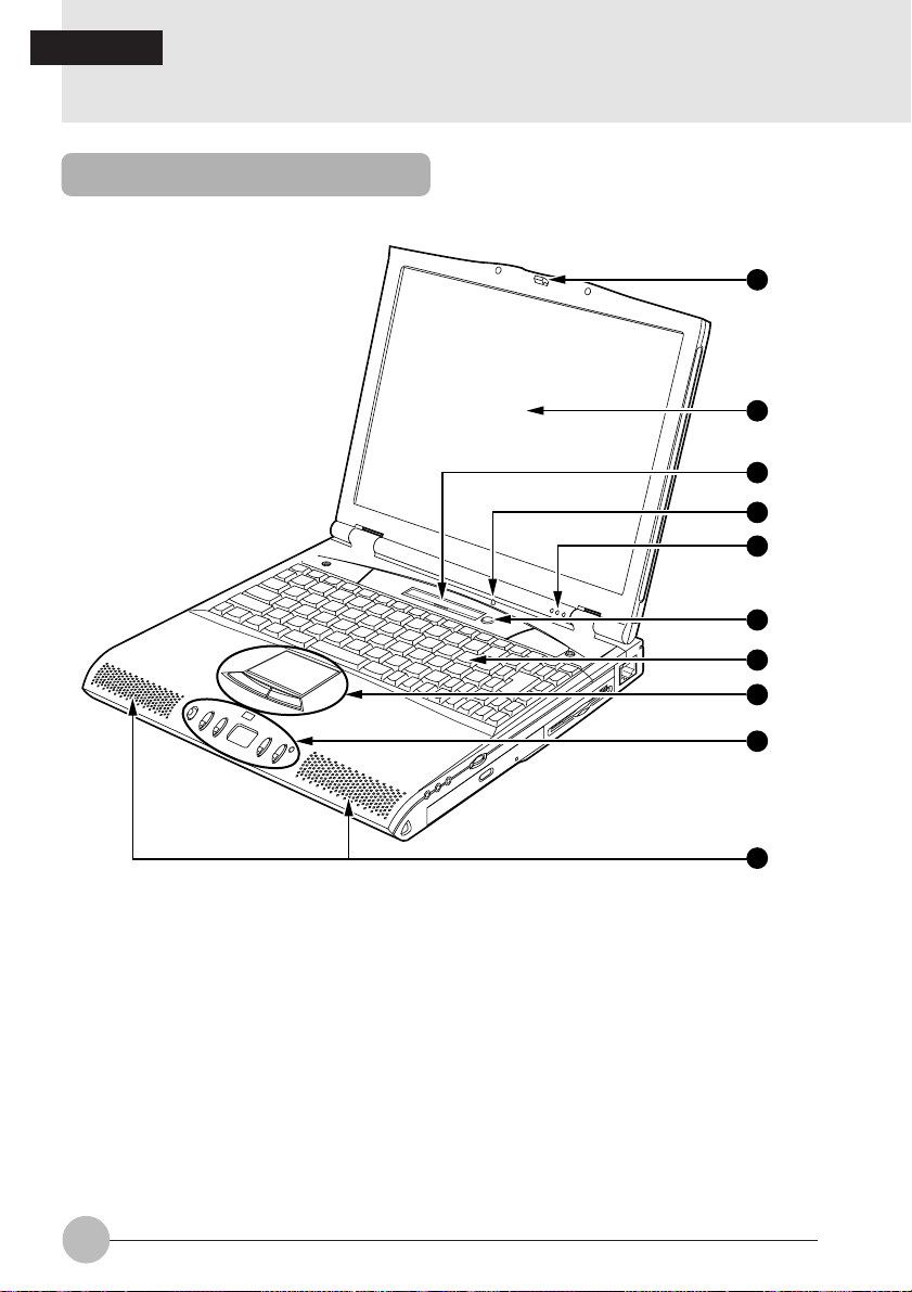
Front
1
2
3
4
5
6
7
8
9
10
2
Page 11

1
Latch
This is pulled to release the lock when the LCD display panel is opened.
2
LCD Display Panel
Displays text, graphics, etc.
3
LCD
Displays the status of the computer main unit. See “Status Indicator LCD”.
4
Closed Cover Switch
This switch puts out the backlighting when the LCD display panel is closed.
5
Condenser Microphone
Allows sound recording.
6
Suspend/Resume Button
This button suspends/resumes the computer main unit. From here on, it is written as SUS/
RES button.
7
Keyboard
Keys are pressed to give commands to the computer main unit.
8
Pointing Device
This moves the mouse pointer.
9
CD/One-Touch Button
Press this button to play back a CD or to activate an application software.
SECTION 1
10
Speaker
Outputs the stereo sound of the computer main unit.
3
Page 12
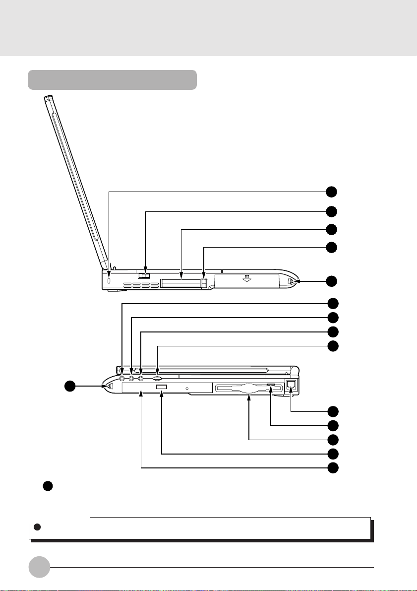
Left Side/Right Side
11
12
13
14
10
15
16
17
18
10
11
Anti-theft lock
Can be connected with a commercially available anti-theft cable.
Critical Point
The anti-theft lock is for the Kensington Microsaver Security System.
4
19
20
21
22
23
Page 13

12
MAIN switch
This is the switch for turning the power to the computer main unit on and off.
13
PC card slot
Slot for inserting separately sold PC cards.
The lower slot is numbered 0 and the upper slot is numbered 1.
14
PC card eject button
Pressed to eject the PC card.
15
Headphone jack
For connecting commercially available headphones.
Critical Point
Things that can be fitted to the headphone jack.
Headphones, earphones, amplifier-installed external speakers (mini-plug with 3.5mm outer
diameter. However you may not be able to fit them because of the shape, so check before
inserting.)
16
Line In jack
Terminal for audio input.
17
Microphone jack
Can be connected with a commercially available microphone.
18
Volume control
Adjusts the sound volume. Turning it towards you lowers the volume; turning it awa y from you
raises it.
Critical Point
If the volume is raised too high when using a microphone, howling may occur between the
speaker and the microphone.
SECTION 1
19
Modular connector
This is for connecting to the telephone line.
20
Floppy disk eject button
Pressed when removing a floppy disk.
21
Floppy disk drive
Used when reading or writing data from/to a floppy disk.
22
EJECT button
Pressed when setting or removing a CD-ROM.
Critical Point
The CD-ROM drive of this unit is locked electrically. A CD-ROM can be set or removed only
when this unit is in operation mode.
23
CD-ROM drive
Used when playing a music CD or using an application software of a CD-ROM.
5
Page 14
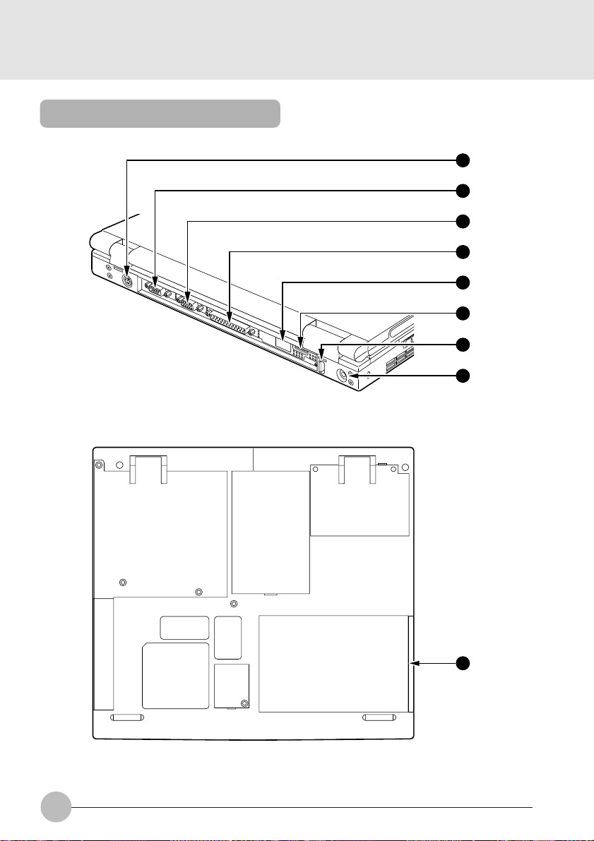
Rear/Bottom
24
25
26
27
28
(available only
29
in Japan)
30
31
ill006J
32
6
Page 15

24
Expansion keyboard/mouse connector
Connector for connecting a separately sold numeric keypad or mouse.
25
Serial interface connector
Connector for connecting separately sold equipment which has an RS-232C standard
interface.
26
CRT interface connector
Connector for connecting a separately sold CRT monitor.
27
Parallel interface connector
Connector for connecting a separately sold printer.
28
Infrared communications port
Interface for carrying out infrared communications.
29
PDC connector (available only with Japanese model)
Connentor for connecting a cellular phone by use of a cellular phone connenting cable which
is separately sold.
30
USB connector (Invalid for the Windows NT system)
Connector for connecting a peripheral equipment which meets the USB standard.
31
DC-IN connector
Connector for connecting the AC adaptor that comes with this computer.
32
Battery pack
Houses a battery pack.
SECTION 1
7
Page 16
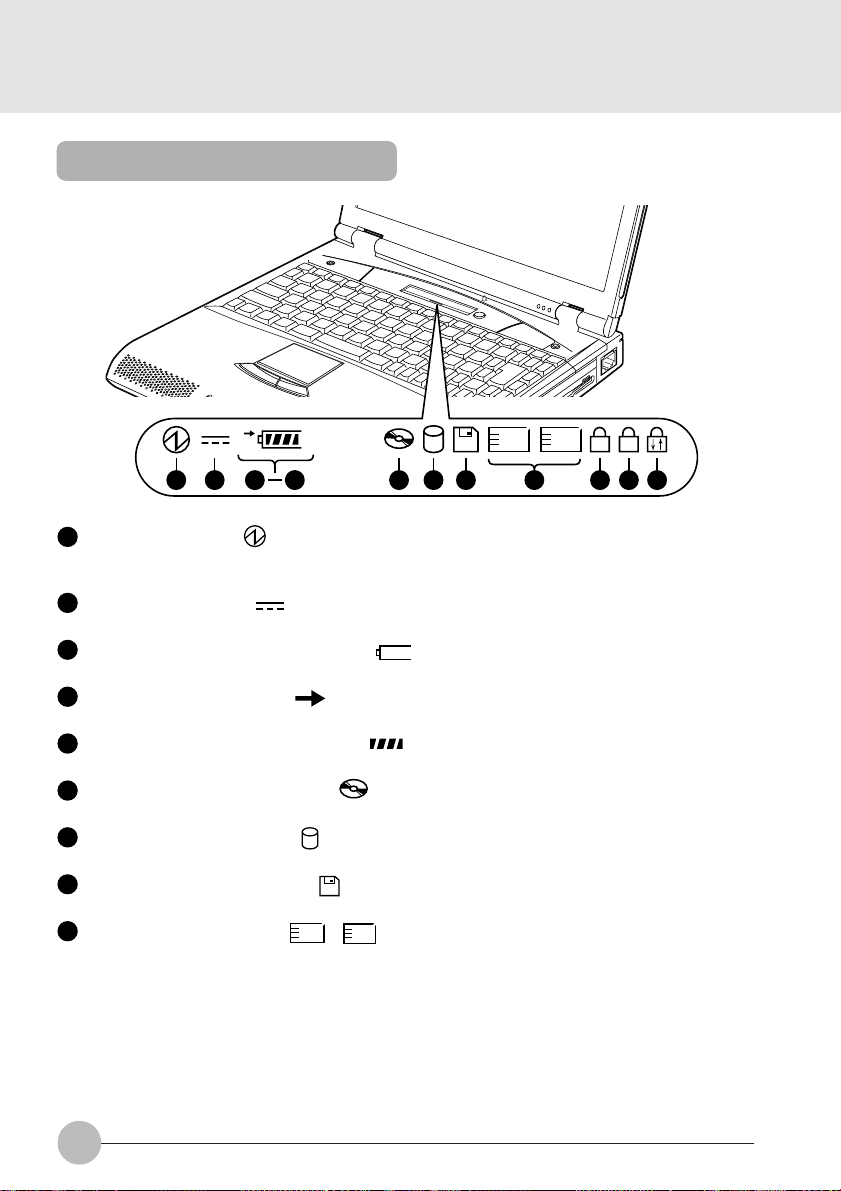
Status Indicator LCD
1
1
2
1
A
1 2 11 12
1
SUS/RES indicator ( )
When this computer is operating, this indicator lights up; when the computer is in suspend mode ,
this indicator flashes.
2
AC adaptor indicator ( )
Lights up when the power is being supplied from the AC adaptor.
3
Battery pack mounting indicators (1, )
Lights up when the battery pack is mounted.
4
Battery charging indicator ( )
Lights up when the battery is charging; flashes when the battery is too hot or cold to charge.
5
Remaining battery charge indicator ( )
Displays the amount of charge remaining in the corresponding battery.
6
CD-ROM drive access indicator ( )
Lights up while data is being read from the CD-ROM.
7
Hard disk access indicator ( )
Lights up while the internal hard disk is being accessed.
8
Floppy disk access indicator ( )
Lights up while data is being read/written on the floppy disk.
9
PC card access indicator ( , 2)
Lights up while the PC card in the corresponding PC card slot is being accessed.
5
3
1
8 9 1076
8
Page 17
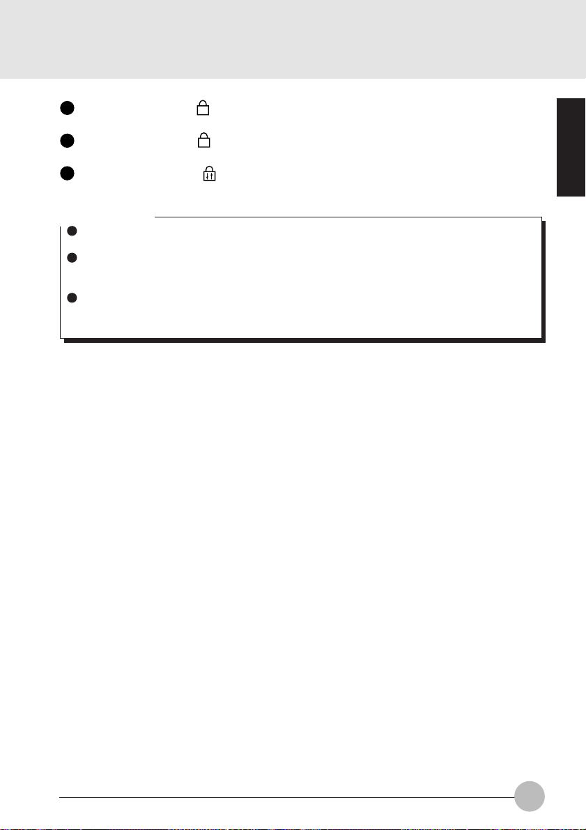
10
Num Lock indicator ( 1)
Lights up when [Shift] + [Num Lk] is pressed to put the keyboard into numeric keypad mode.
11
Caps Lock indicator ( A )
Lights up when [Shift] + [Caps Lock] is pressed to put the keyboard into CAPS mode.
12
Scroll Lock indicator ( )
Lights up or goes out each time the [Scr Lk] key is pressed.
Critical Points
If you turn off the main switch or operate the SUS/RES button while the hard disk access
indicator or floppy disk access indicator is lit, the data being accessed may be destroyed.
When the main switch is switched off, all the indicators other than charging go off. However,
the AC adaptor lamp comes on regardless of the status indicator lamp when power is being
supplied.
When you use Windows 98, if the CD automatic insertion function is enabled, the system
periodically checks for a CD. Therefore, the CD-ROM drive access indicator on the status
indicator LCD lights up periodically.
SECTION 1
9
Page 18
SECTION 1
2. Keyboard
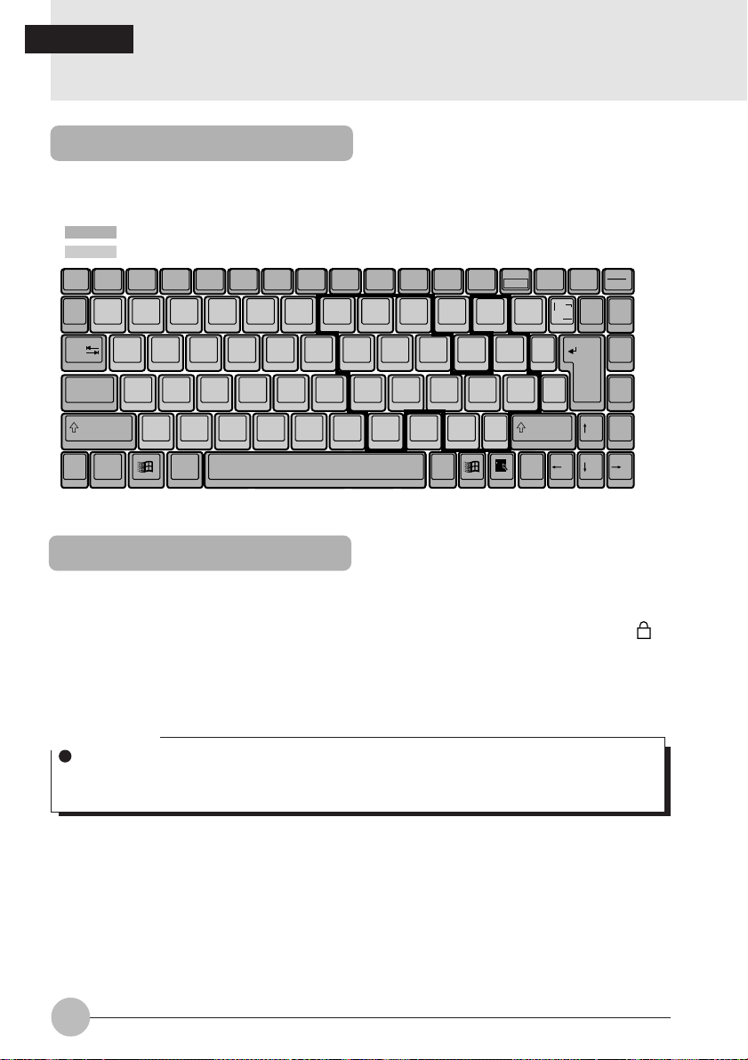
Keyboard
The keyboard is the device for giving instructions to the computer, inputting data, and executing.
The keys can be divided into two types.
: Control keys
: Character keys
Num Lk
Insert
Delete
F1Esc F2 F3 F4 F5 F6 F7 F8 F9 F10 F11 F12
~
!@
`
1
Q W E R T Y U I O P
Tab
CapsLock
Shift Shift
Fn
Ctrl Alt
#
$
%
2
3
4
A S D F G H J K L :
Z X C V B N M
^&
5
7
6
789
456
()
*
8
123
0
0
9
<
>
,
.
Alt Ctrl
—
-
-
;
?
/
Scr Lk
Prt Sc
+
=
{
}
]
[
"
'
*
\
}
]
SysRq
Enter
Back
Space
Pause
Break
Pg Up
Pg Dn
Home
End
Numeric Keypad Mode
The mode in which some of the character keys are used as numeric keys (with a key layout that
makes numeric input easier) instead of their normal functions is called numeric keypad mode. The
keyboard is switched to numeric keypad mode with [Num Lk]. (In numeric keypad mode, 1 is
displayed on the status indicator LCD.) The keys surrounded by thick lines in the diagram above
become the numeric keypad. The numbers input with these keys are printed in pink on the front of
each key.
Critical Point
When the separately sold numeric keypad is connected, if you press [Num Lk] to put the
computer into numeric keypad mode, the keys on the external numeric keypad are enabled,
but the numeric keypad section on the keyboard is disabled.
10
Page 19

Names of the Main Keys and their Functions
[Esc] (escape) key
The usage is determined by the application software. It is often used to return to the
previous operation.
[F1]-[F12] (function) keys
The usage depends on the application software.
[Fn] key
A key unique to this computer; it has the following functions.
[Fn] + [F3] This switches ON/OFF of the speaker.
When a pip sounds with this operation, the speaker is on. When nothing
sounds, the speaker is turned off.
[Fn] + [F5] This selects whether or not to use the entire LCD display panel for display
in text mode.
[Fn] + [F6] Turns down the backlight of the LCD.
[Fn] + [F7] Turns up the backlight of the LCD.
Critical Point
Luminance of the backlight of the LCD can be turned up (with [Fn] + [F7] keys) or turned
down (with [Fn] + [F6] keys) in three degrees.
[Fn] + [F10] Rotates among the three display options: LCD only, CRT only , both LCD
and CRT.
[Space] key
Inputs a single space character.
(This is the long key with nothing written on it at the center of the front of the ke yboard.)
SECTION 1
[↑] [↓] [←] [→]
[Enter] key
[Ctrl] (control) key
(cursor) keys
Move the cursor.
Also called the return key or the line feed key. This key inputs line feeds and executes
command.
Used in combination with other keys; its functions depend on the application software.
11
Page 20

[Shift] key
[Alt] key
[Caps Lock] key
[Num Lk] (numerical lock) key
[Scr Lk] (scroll lock) key
[Print Screen] key
[Pause] key
[Break] key
[Insert] key
[Delete] key
[Home] key
[End] key
[Page Up] key
[Page Down] key
[Back Space] key
Used in combination with other keys.
Used in combination with other keys; its functions depend on the application software.
T o loc k the ke yboard into caps mode , press this k ey together with the Shift k ey. Pressing
this key again ends caps mode.
Press this key to put the computer into numeric keypad mode.
Its functions depend on the application software.
Press this key to make a hard copy of the screen.
Press this key to pause the screen display.
Its functions depend on the application software.
Press this key to insert a new character between characters. The new characters are
entered at the cursor position.
Press this key to delete a character . Pressing the Delete key and the [Ctrl] and [Alt] keys
at the same time resets this computer.
Press this key to move the cursor directly to the head of the row or the head of the
document.
Press this key to move the cursor directly to the end of the ro w or the end of the document.
Press this key to switch to the previous screen.
Press this key to switch to the next screen.
Press this key to delete the character to the left of the cursor position.
12
Page 21

[Sys Rq] (system request) key
When this key is supported by the application software, this ke y is used for such functions
as resetting the keyboard. Press this key together with the Alt key.
[ ] (Windows) key
Press this key to display the Start menu.
[ ] (Application) key
Press this key to display the shortcut menu for the selected item. This key has the same
role as the mouse right click.
SECTION 1
13
Page 22
SECTION 1
3. Turning on the Power
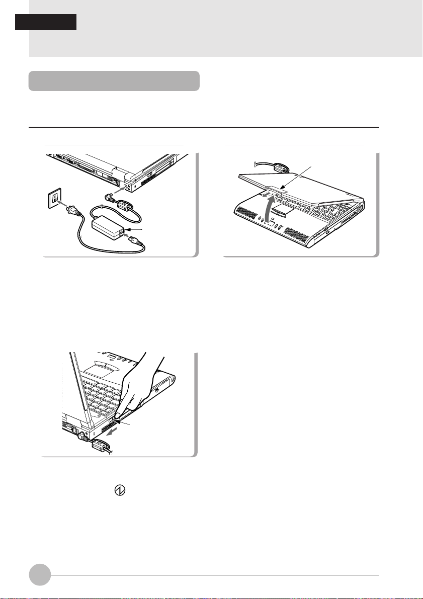
Turning on the power
This item explains the normal way to turn the computer main unit power on and off.
1 Connect the AC adaptor.
AC adaptor
3 Switch on the main switch of the compu-
ter main unit.
MAIN switch
2 Open the LCD display panel.
Latch
Pull the latch to release the lock, then lift the
display panel with your hand.
Power is supplied from the A C adaptor or the
battery, the power comes on, and the POST
starts. Also, the etc. on the status
indicator LCD are displayed.
14
Page 23
Critical Point
Do not carry this computer around or subject it to shock or vibration with the power on. These
can result in breakdown.
Column
POST is the abbreviation for POWER ON SELF TEST, which is a self-diagnostic test that
checks for abnormalities within the computer. This test is automatically carried out when the
power is switched on for this computer. If the power is switched off during the POST, an error
message is displayed the ne xt time the computer is started up. Do not cut off the po wer during
the POST.
SECTION 1
15
Page 24
SECTION 1
4. Turning off the Power
Turning Off the Power
This item explains how to turn off the power.
Critical Points
Do not turn back on the computer immediately after turning it off, but wait for 10 seconds or
so.
When the computer is not used for a long time, unload the flopp y disk and the CD-R OM from
the computer before turning it off.
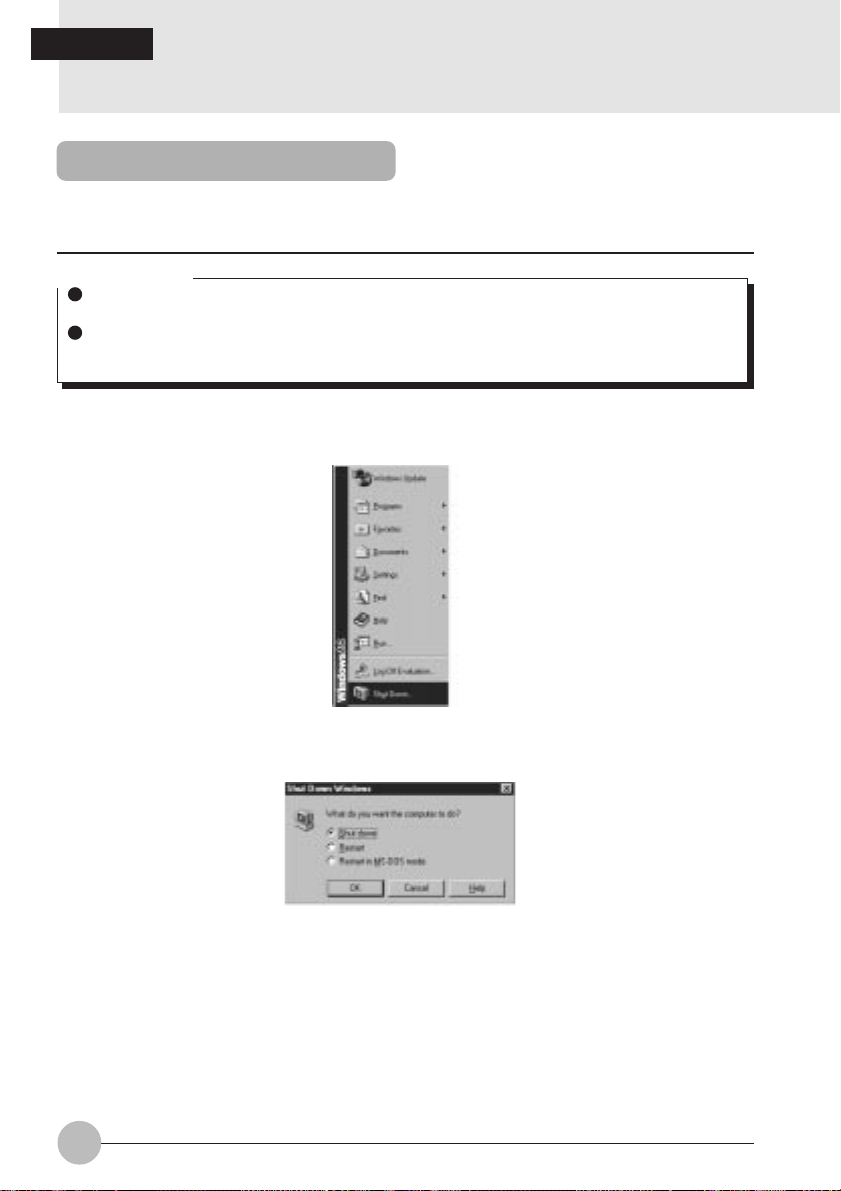
1 Click the [Start] button.
The Start menu is displayed.
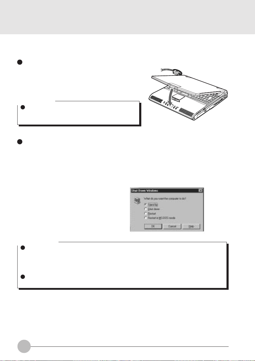
2 Click [Shut Down].
The following message is displayed.
3 [Check that Shut down the computer is selected, then click Yes].
The power is turned off. If the computer will be unused for a long period, disconnect the AC
adaptor.
16
Page 25
Critical Points
If the MAIN switch is not turned off after the step 3, press the SUS/RES button to turn on the
personal computer next time.
If “Restart” or “Restart computer” is selected on the dialog box that appears as a result of the
steps 2, the personal computer will be restarted. “Restart” means that the personal computer
erases all data saved in the memory once and again reads the program of the operating
system from the floppy disk or hard disk into it.
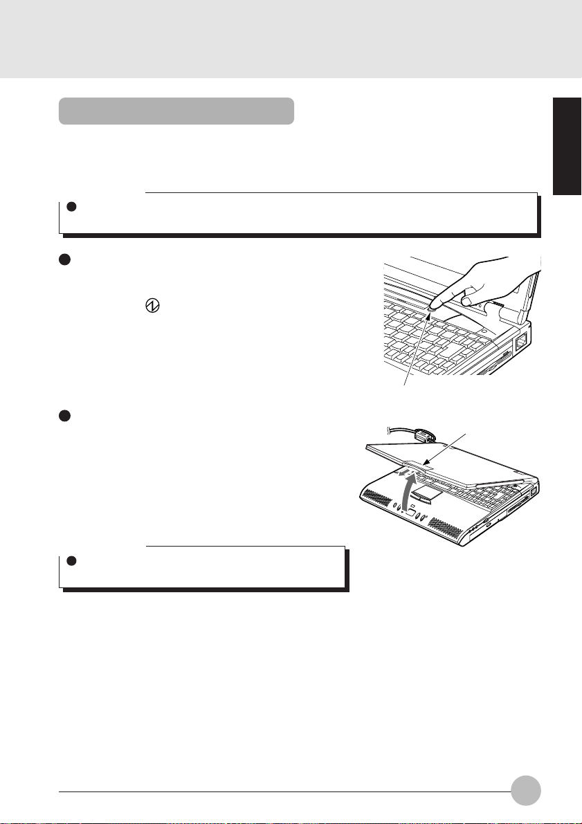
4 Turn off the MAIN switch.
Slide the MAIN switch in the direction of the
arrow (toward side).
MAIN switch
Critical Point
If the personal computer won’t be used for a long time after this step, be sure to disconnect
the AC adaptor and to remove the battery pack from it.
SECTION 1
17
Page 26

SECTION 1
5. Suspend/Resume Function
What Is the Suspend/Resume Function?
When this computer is suspended with the SUS/RES button, the suspend/resume function retains
the programs and data in memory as is so that you can resume operations immediately the next time
you press the SUS/RES button.
Precautions for Suspending
Pay attention to the following points when using the suspend function.
Do not hold down the SUS/RES button for more than 4 seconds, otherwise the computer will
be turned off.
When the computer is connected to a network using a LAN or modem and when the peripheral
equipment is expanded with a PC card, you may not be able to use the suspend/resume
function. When you have expanded functions with a PC card, also check the manual for the
cards you are using.
Do not operate the SUS/RES button when using Windows NT.
In the following cases, do not use the suspend function, b ut turn on/off the computer main unit
power supply with the main switch.
• When this computer is unused for a long period
When this computer will be unused longer than the effective period (about one da y maximum)
for battery power for suspend mode, sa ve all data, close Windows 98, then turn off the main
switch. If you suspend with the BIOS setup Suspend Mode set to Save to Disk, the power
goes off with the main switch still on. In this case , it does not matter if you turn off the main
switch. The next time you turn on the main switch, operation resumes.
• When installing or removing options
There are some options that can be installed without turning off the main switch. See
SECTION 2 of this manual and the manual that comes with the option product.
Critical Points
The SUS/RES button does not work in the following cases.
If the battery is dead while the computer is powered from it.
When the BIOS setup SUS/RES button is set to disabled.
18
Page 27
Suspending
There are three ways to suspend this computer, using the SUS/RES button, Closed Cover
switch and for Windows 98, using the [Shut Down] dialog.
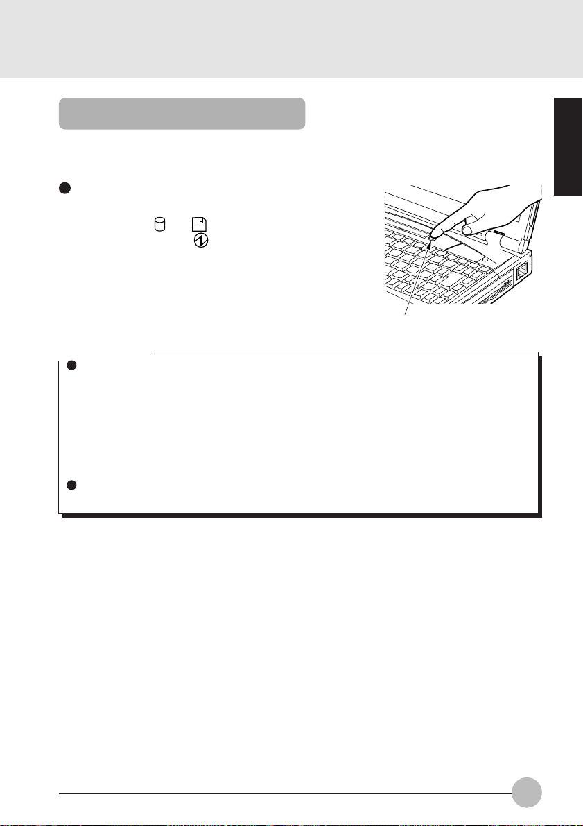
Using the SUS/RES button
1 Suspending
Check that and are out. When you press the
SUS/RES button, flashes and the computer
goes into suspend mode.
SUS/RES button
Critical Points
Which of the two destinations suspending saves the data in the computer to depends on the
BIOS setup Power menu setting as follows.
System RAM:
When “Suspend” is set with the BIOS setup Power menu “Suspend Mode” item, the data
is saved to system RAM. P o wer f or the system RAM is supplied from the AC po wer supply
if the AC adaptor is connected or from the battery if the AC adaptor is not connected.
Save to Disk area:
If “Save to Disk” is set with the BIOS setup Power menu “Suspend Mode” item, the data is
written to the Save to Disk area on the hard disk.
If you hold down the [Fn] key while pressing the SUS/RES button, the data is saved to the
hard disk regardless of the Power menu setting.
SECTION 1
19
Page 28
Using the Closed Cover switch
1 Close the LCD display panel.
This unit goes into suspend mode using the Closed
Cover switch.
Critical Point
When the BIOS setup “Lid Closure Suspend” setting
is “Disabled”, this unit does not go into suspend mode
even if you close the LCD display panel.
Using the [Exit Windows] dialog box.
1 Click on the [START] button, then on [Exit
Windows].
The [Exit Windows] dialog box will appear on the
screen.
2 Choose [Standby] and click on [OK].
This computer is suspended.
Critical Points
If the BIOS setup Suspend Mode setting is “Suspend”, suspend mode is ended in the following
cases. Save important data to a floppy disk or the hard disk.
• The main switch is switched off.
• In battery operation, the battery runs out.
(The battery is still used in suspend mode.)
If you start with the internal battery fully charged, suspend mode lasts about one day maximum
with the AC adaptor not connected.
20
Page 29
Using the Resume Function
You can make the computer resume the current application program, using either the SUS/
RES button or the closed cover switch.
Critical Point
Immediately after putting it into the Suspend mode, do not make the computer resume the
program but wait for 10 seconds or so.
Using the SUS/RES button
1 Press the SUS/RES button.
Pressing the SUS/RES button will cause the
indicator on the status display panel to stop
blinking and light up permanently , and will bring the
computer into operation.
SUS/RES button
Using the closed cover switch
1 Open the LCD display.
Opening the LCD display will turn on the Cover
Close switch and make the computer resume the
current program.
Latch
SECTION 1
Critical Point
The Resume function does not operate if Lid Open
Resume in the BIOS Setup dialog box is not selected.
21
Page 30
SECTION 1
6. Battery
Battery Charging
For portability, this computer can operate either from the AC adaptor or from its battery.
This item explains how to charge the battery.
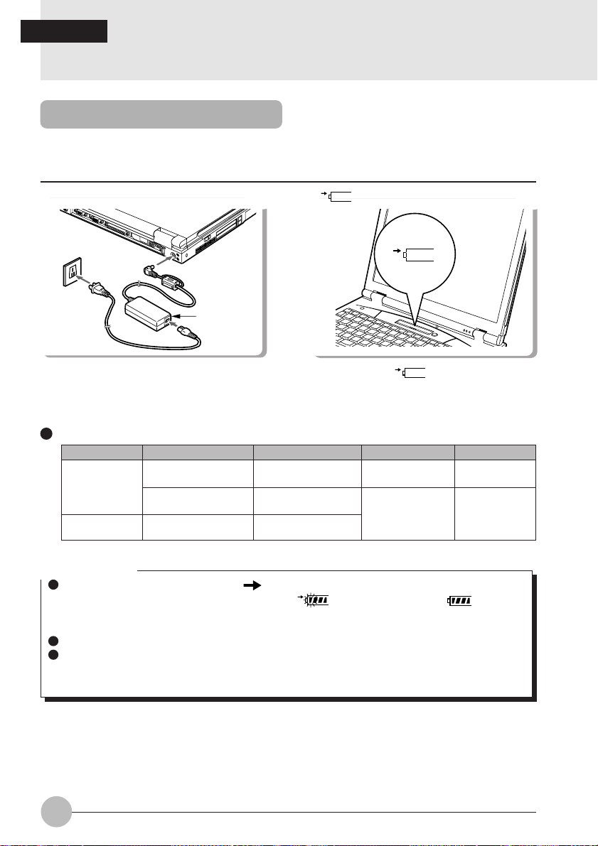
1 Connect the AC adaptor.
AC adaptor
Relationship between computer modes and battery charging time
Main switch SUS/RES button Computer mode Charging mode Charging time
ON
OFF
Resume Standard charging
Suspend
––
Operating mode
Suspend mode
1
2
During charging,
status indicator LCD and the remaining battery
charge is displayed.
Stopped
is displayed.
1
1
Quick charge
is displayed on the
About XX hours
About XX hours
Critical Points
When the battery charge indicator ( ) goes out and status of the remaining battery power
indicator on the left side changes from blinking ( ) to continuous lighting ( ),charging
the battery is complete. Spend considerable hours for charging the battery so that it is fully
charged.
The battery capacity falls if the ambient temperature is too low or too high.
Just after use of the battery , charging it ma y result in f ailure because the battery temperature
has risen and the battery protection function is activated. In such the case, leave the battery
in the charging status and charging will start a while later with drop of the battery temperature.
22
Page 31

Battery Operation
This item explains operation with the battery.
1 Disconnect the AC adaptor and s witch on
the main switch.
Main Switch
2 When the main switch is on, press the
SUS/RES button.
SUS/RES switch
stops flashing and stays lit up.
Critical Points
When the ambient temperature is lower, the battery operating time is reduced.
With this computer, the battery operating time depends on the conditions under which the
battery is used. However, the operating time of a new, fully-charged battery is about 1.5 to 3
hours.
Condition: Main unit only, full charge, with power management on. (The yardstick for
operating time depends on the conditions of use.)
SECTION 1
23
Page 32

Checking the Remaining Battery Charge
This computer can indicates the amount of battery charge remaining with the remaining battery
charge indicator on the status indicator LCD.
Remaining battery charge indicator
Indicates battery charge level of about 76% to about 100%
Indicates battery charge level of about 51% to about 75%
Indicates battery charge level of about 26% to about 50%
Indicates battery charge level of about 16% to about 25%
Indicates the low battery state (battery charge level of about 15% or
lower). flashes.
Indicates that the battery has run out (0% charge level).
Battery abnormality indicator
Indicates that the battery can not be charged normally.
Critical Point
When is displayed, take out the battery pack and re-install it. If this displa y still remains,
the battery pack is abnormal, so replace it.
24
Page 33

Low Battery State
This item explains the display when this computer’s battery is low and what to do.
1 The low battery is announced in the following way.
The warning beeps and the battery mark on the status indicator LCD flashes.
Critical Point
If the audio volume is set too low, you may not be able to hear the warning beep. When the
speaker is set to OFF using [Fn] + [F3] keys, the warning beep does not sound.
2 Press the SUS/RES button.
When the battery goes low, quickly press the SUS/RES button to suspend operation. Since
the suspend/resume function works even if the computer is suspended during operation, the
program and data are not lost.
Critical Point
If you want to resume operation immediately, connect the AC adaptor, then press the SUS/
RES button again.
3 Charge the battery.
Connect the AC battery to charge the battery.
Critical Points
Reading from and writing to the hard disk uses large amounts of power . When saving data to
the hard disk with the battery low, connect the AC adaptor.
If you leave this computer running with the battery low , it is suspended automatically . How ever ,
if data is being read from or written to the hard disk or other media, the suspending waits until
that processing is complete.
If you continue using the computer with the battery low, in the worst case, the data being
created or saved may be lost. Quickly connect the AC adaptor.
SECTION 1
25
Page 34

Replacing the Battery Pack
W ARNING
(ELECTRIC SHOCK)
Before replacing the battery
pack, be sure to turn off the
computer and disconnect the
AC adaptor from it.
Otherwise you might get an
electric shock.
2 Slide the cover of the battery pack.
1 T urn off the computer and disconnect the
AC adaptor from it.
3 Slide the battery pack towar ds you (in the
direction opposite to the connector).
Connector
Battery pack
26
The battery pack is disconnected from the
connector of the built-in battery pack slot.
Page 35

5 Install a new battery pack.4 Remove the battery pack.
Battery pack Battery pack
SECTION 1
Slide
guide
Tilt the battery pack up and then take it
out of the battery pack slot in a tilt
direction.
While tilting up the battery pack cover,
slide the battery pack and connect the
connector.
Put the battery pack in the slot by positioning
the slide guide with the main unit.
7 Slide the battery pack cover.6 Connect the connector.
For locking the battery pack cover that was
once slid in the previous step 2, again slide
it to its original position.
27
Page 36

Bridge Battery
The bridge battery is a NiCd battery that is built-in your notebook and is constantly being recharged.
A bridge battery allows a charged Lithium ion battery to be exchanged for a discharged one by
“warm-swapping”.
To warm-swap hav e a charged battery ready, put your notebook in Suspend mode, remove the low
battery and quickly insert a charged battery. The bridge battery capacity is not large, about 3 minutes, and can vary with the condition of your notebook.
Caution
Data may be lost and/or system errors introduced if the warm swap is not performed
quickly or a power adapter installed
Caution
The bridge battery can not suppor t an operating notebook. The notebook must be in
Suspend mode.
28
Page 37

Precautions for Battery Pack
W ARNING
(ELECTRIC SHOCK)
The battery pack is an extremely delicate products. When installing or removing one, do
not drop it or subject it to strong shocks. If this should happen, do not use that battery
pack in the interest of safely, because there is a risk of electric shock or malfunction.
Discharge
After you charge the battery pack, even if y ou store it without using it, o v er about 1 month it will
naturally discharge.
Service life
•The battery pack is a consumption item. After you use it f or a long time, its charging capacity
drops.
•Replace the battery after about 300 to 500 charge/discharge cycles.
•When the battery operating time becomes extremely short, the battery has reached the end
of its service life.
To extend the battery operating time
Use the BIOS setup Power menu.
Conditions under which the battery operating time becomes shorter
•Using in cold or hot location
The battery operating time is influenced by the environmental temperature and the battery
operating time can be shorter at low temperature (5°C) then at high temperature (35°C).
Also, high temperatures not only lower the charging efficiency, but are also a cause of battery
pack deterioration.
•When the battery charging capacity drops
When the battery pack has been used for a long time, its charging capacity drops. In this
case, replace it with a new battery pack.
SECTION 1
Use the AC adaptor in the following cases
• When using the hard disk or CD-ROM frequently
• When using a LAN or a modem
29
Page 38

SECTION 1SECTION 1
7. Floppy Disk Drive
Loading/Ejecting a Floppy Disk
This item explains how to load and eject a floppy disk.
Loading
Insert into the floppy disk drive.
Eject button
Insert the floppy disk with the label
upwards and the shutter side first until the
EJECT button springs out.
Critical Points
If you eject the floppy disk while is still
indicated, there is a risk of losing the data on
the disk.
When you do not want to erase the data sav ed
on the disk, or when you do not want to write
additional data, slide the floppy disk’s write
protector so that the hole is open (WRITE
PROTECT state). When you want to write
data again, slide the write protector so that
the hole is closed.
Ejecting
Press the EJECT button.
Eject button
Check that the on the Status Indicator
LCD is not on, then press the EJECT button.
Write protector
WRITE ENABLE
WRITE PROTECT
30
Page 39

What is a Floppy Disk?
A floppy disk is a medium for storing programs or data. This item explains basic knowledge
and precautions regarding floppy disks.
Types of floppy disks
If floppy disks are classified according to the amount of data they can store (the memory
capacity), typically there are the following 2 types.
•2HD floppy disks
These have 1.44MB (megabyte: unit of data
amount) and 1.2MB memory capacities.
• 2DD floppy disks
These have 720KB (kilobyte) memory
capacities, half of the 2HDs.
The differences between the 2 kinds of floppy
disks are shown in the diagram on the right.
3 mode drive
This computer’s floppy disk drive is a 3 mode drive that can read 1.44MB, 1.2MB and 720KB
memory capacity floppy disks. Therefore it can read nearly all floppy disks. However, when
exchanging data with another computer, you have to be careful if the other computer’s floppy
disk drive is not a 3 mode drive. For example, if the other computer can read 1.2MB floppy
disks but not 1.44MB floppy disks, y ou hav e to enter the data after putting it into 1.2MB f ormat
in advance with this computer.
HD mark or no mark
2HD 2DD
Hole or no hole
SECTION 1
Critical Point
Some floppy disks cannot be read by this computer, depending on the floppy disk format.
31
Page 40

Precautions on Handling
Take the following precautions when using floppy disks in order to avoid damaging them.
Be careful not to spill liquids such
as coffee onto them.
Never touch the surface of the
disk.
Do not place them in places with
high temperatures or in direct
sunlight.
Do not bring them near to
magnetic fields.
Do not bend them or place heavy
objects on top of them.
Do not stick labels on over each
other.
32
Page 41

SECTION 1
COMPACT
DIGITAL AUDIO
8. CD-ROM Drive
CD-ROMs
Take the following precautions when handling CD-ROMS.
When removing a CD-ROM from its case, lift it
out while pressing the center holder of the case,
as in the diagram on the right.
Handle the CD-ROM by its edges, trying as much
as possible not to touch the surfaces.
Store the CD-ROM in its case when not using it.
Do not leave it in a high temperature place.
Do not bend it or place heavy objects on it.
Do not write with a ballpoint pen, pencil, etc. on
the label surface (printed side).
If you suddenly move the CD-ROM from a cold place such as outside to a warm place,
condensation will form on the surface and the CD-ROM drive will be unab le to read data. If this
happens, wipe the CD-ROM with a dry soft cloth, and then allow it to dry naturally. Do not use
anything like a hairdryer, etc. to dry it.
Critical Points
If the CD-ROM gets dirty , wipe it clean with a dry soft cloth from the center outwards. Do not
wipe it with benzine, paint thinner, water, record spray, antistatic solution or silicon cloth.
A CD-ROM is a ROM that stores computer data
instead of the audio data stored on music CDs
(compact disks).
ROM stands for Read Only Memory, which
means it is a memory medium that can only read
data and cannot write data later. The CD-ROMs
which are marked as in the diagram on the right
can be used with this computer.
A little time is required after installing a CD-ROM until the computer recognizes it.
COMPACT
COMPACT
DIGITAL AUDIO
COMPACT
DIGITAL VIDEO
SECTION 1
33
Page 42

Loading/Ejecting a CD-ROM
This item explains how to load/eject a CD-ROM.
Critical Point
There is a protective sheet on the
expansion unit’s CD-ROM tray upon
delivery . Remo ve this sheet when you use
the CD-ROM drive.
You can only install/eject a CD-ROM
when the computer main unit is in
operating mode because of the electronic
lock of the CD-ROM drive.
2 Pull the tray out.
1 Press the EJECT button.
EJECT button
The tray springs out slightly.
3 Put in the CD-ROM.
Pull the tray out gently.
34
Place the CD-ROM in the center of the tray
with its label facing upwards.
Page 43

4 Set the tray.
Push the tray in gently.
Critical Points
CD-ROM drive is an extremely delicate de vice in which the CD-R OM revolves at high speed.
Do not carry it when the power to the computer is switched on, and do not expose it to shoc ks
or vibrations.
When ejecting a CD-ROM, carry out the same procedure as for loading.
If for some reason the tray does not come out when you press the eject button, insert something like a clip into the hole to the right of the EJECT button on the front of the CD-ROM drive
unit and pull out the tray.
SECTION 1
35
Page 44

SECTION 1
9. Internal Fax Modem
What is a Fax Modem?
A modem is a device for exchanging data between a computer and a telephone line. If you have a
modem, you can carry out computer communications (connecting computers by a telephone line
and exchanging information).
A fax modem is a modem which, in addition to the above functions, has a function of sending data
to a fax machine. Therefore, when you transmit a document to another person’s fax machine, you
don’t have to go to the trouble of printing out the document and setting it in your fax machine.
You can also receive data sent from a fax machine.
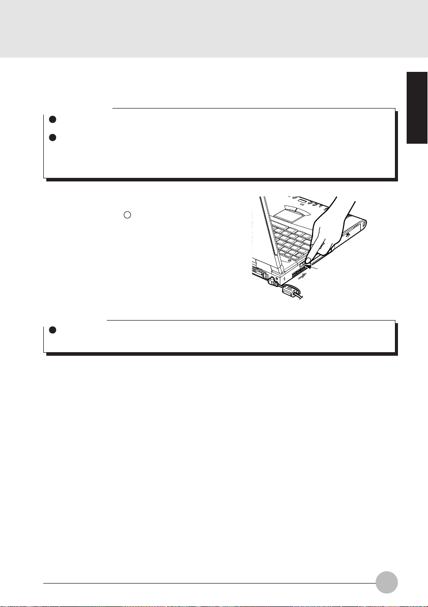
Connection
Connect the modular cable jack from the line junction into the modular connector on the rear of the
computer main unit.
Critical Point
When you remove the modular cable, press
down the hook of the modular plug and pull it
out.
36
Page 45

Modem Warnings
CAUTION
The internal modem has a maximum speed of 56000bps by ITU-T V.90 standard. Its
maximum speed of 53000bps is the highest allowed by FCC , and its actual connection
rate depends on the line conditions. The maximum speed is 33600bps at upload.
CAUTION
The internal modem is not intended for use with Digital PBX systems. Do not connect
the internal modem to a digital PBX as it may cause serious damage to the internal
modem or your entire notebook.
Consult your PBX manufacturer’s documentation for details. Some hotels have digital
PBX systems.
Be sure to find out BEFORE you connect your modem.
SECTION 1
37
Page 46

SECTION 1
10. SPDIF Features
How to use the SPDIF Output Connector?
Please use the following settings when using the SPDIF output connector.
1 Click Start and choose Settings.
2 Choose Control Panel and double click the Yamaha DS-XG Audio Config.
3 Click on the SPDIF tab and select ON (Digital Sources Only).
SPDIF Connector
CAUTION
(INJURY)
Do not look into the SPDIF connector when inserting the cable jack into the connector
as there is a strong light beam emitting from the connector.
(BREAKDOWN)
Tur n down the audio volume when connecting electronic devices to the Line In jack.
Extremely loud audio volume will cause damage to the internal speakers.
Critical Point
The frequency of the digital sound output from the SPDIF output connector is fixed at 48kHz.
If a sampling rate convertor is not installed in your connected digital electronic device (e.g.
MD player), recording is not possible. Please refer to the user’s manuals for the electronic
devices for further details.
The sound recorded through the connected digital electronic device (e.g. MD player) to the
SPDIF output connector cannot be used as a digital output. All output data from the SPDIF
output connector has copyright protection information included.
Please be careful to use the correct type of cable to connect the digital electronic device (e .g.
MD player) to the SPDIF output connector . The type of connector that is used on y our computer is a Optical Mini Plug (3.5mm diameter mini plug).
38
Page 47

SECTIONSECTION
SECTION
SECTIONSECTION
SECTIONSECTION
SECTION
SECTIONSECTION
22
2
22
22
2
22
This section explains installation
of options for this computer.
SECTION 2
Page 48

SECTION 2
1. Options
Options
You can expand the functions of this computer by connecting various options. Connecting options
such as a printer or a modem card makes it possible to print documents created with this computer
and to communicate them to other computers.
Other options include hard disks and expansion memory. Install options to match this computer to
your usage objectives.
IC memory card
SCSI card
Modem card
LAN card
Expansion RAM
module
Printer
Numeric key pad
Color CRT display
Mouse
40
Page 49

WARNING
(ELECTRIC SHOCK)
Only connect equipment recommended by Fujitsu.
Connecting any other equipment can cause electric shock, fire, or breakdown.
CAUTION
(INJURY)
When installing/removing options, do not remov e any screws other than those specified
by this manual.
Removing any other screws can cause injury and breakdown.
(BREAKDOWN)
Read this manual carefully and connect cables correctly. If you use this computer with
cables connected incorrectly , this can cause breakdo wn of the computer main unit and
of the peripheral equipment.
SECTION 2
41
Page 50

SECTION 2
2. PC Cards
Precautions for PC Cards
Observe the following points when using PC cards to prevent breakdown.
Do not place PC cards in hightemperature locations and
locations subject to direct
sunlight.
Do not place heavy objects on
top of PC cards.
Do not subject PC cards to
strong shocks.
Be careful to avoid spilling coffee
and other liquids on PC cards.
Avoid rubbing PC cards and
building up static electricity.
When storing a PC card, always
place it in its special case.
42
Page 51

Installing PC Cards
PC card is a generic term for business card sized cards which have a program and data
memory function or peripheral equipment functions such as a modem or LAN adaptor. This
item explains how to install a PC card.
1 Install the PC card.
PC card
Insert the PC card into the PC card slot
with the product name facing upwards.
Critical Points
For some PC cards, the main power s witch should be turned off. Ref er to the manual attached
to your PC card.
In order to avoid damage, be careful not to knock or put anything on top of the connection
point between the PC card and the cord.
SECTION 2
43
Page 52

Removing PC Cards
This item explains how to remove a PC card.
1 Click the PC card indicator on the task bar.
A message is displayed for stopping the installed PC card.
2 Click the PC card to be removed.
The PC card operations stop and the following screen is displayed.
Critical Point
For IC memory cards, the “This device cannot be removed” message may appear. If this
message does appear, close Windows 98 and turn off the computer main unit power before
removing the IC memory card.
3 Click [OK].
44
Page 53

4 Press the PC card eject button.
5 Remove the PC card.
SECTION 2
PC card eject button
The PC card eject button slightly juts up.
PC card
Press the PC card eject button to eject
the PC card.
PC card
eject/lock button
Critical Points
Never remove a PC card by pulling on its cord. Yanking on the cord can break the PC card.
Always use the procedure above for removing PC cards. Removing PC cards in any other
way can cause breakdown.
45
Page 54

SECTION 2
3. Expansion RAM Modules
Installing an Expansion RAM Module
This item explains how to install expansion RAM modules.
W ARNING
(ELECTRIC SHOCK)
Always turn off the computer main
unit main switch and disconnect the
AC adaptor when installing an
expansion RAM module in order to
avoid electric shock.
2 Fold out the LCD panel horizontally. First remove the screw covers from the front top
cover of the keyboard next remove the front top cover.
1 T urn off the computer and disconnect
the AC adaptor from it.
For removing the screw co v er, insert a thin stick like a needle into either of pinholes on both sides of
each screw hole on the front top cover and then raise the screw cover by it.
46
Page 55

Critical Point
When closing the keyboard, be sure to insert its tabs securely into the locating holes in the
computer main unit.
3 Open the keyboard.
While sliding the keybaord slightly to the
rear side, open it gently.
5 Install an extension RAM module.
4 Open the seat cover.
SECTION 2
6 Return the keyboard to its original
position.
With the cutouts of the extension RAM
module aligned with the protrusions on
the connector, insert diagonally the
RAM module into the connector until it
clicks in place.
Close the keyboard, and then slide it to the
front side so that its front pawls are securely
inserted into the holes on the computer
frame.
47
Page 56

7 Fit the cover to the computer main
unit and fastern it with the screws.
Restore the cover to the computer main
unit and fasten it with the screws, both
of which were once removed in the
previous step 2.
Critical Point
When fitting the cover to the computer
main unit again, firmly insert the pawls
into the holes on the back of the
computer main unit.
back of main unit.
holes
CAUTION
(DAMAGE)
The expansion RAM module is made up of parts that are extremely vulnerable to
static electricity and can be damaged by the static electricity built up inside the main
unit. When installing or removing an e xpansion RAM module , hold it b y the edges. Do
not touch any terminals or ICs. Also, do not touch any parts or terminals within the
computer main unit.
Checking expansion memory
To check expansion memory after installing an expansion RAM module, look at the [DIMM]
item in the Info menu of the BIOS setup . For example, when a 32MB expansion RAM module
has been installed, the number displayed is 32MB greater than the initial v alue. If the expansion
RAM module has been installed correctly but the number has not display ed, it means the RAM
module is either broken or defectiv e. If this happens, contact the store where the RAM module
was purchased.
48
Page 57

Removing an Expansion RAM Module
This item explains how to remove an expansion RAM module.
WARNING
(ELECTRIC SHOCK)
Always turn off the computer main unit main switch and disconnect the AC adaptor
when removing an expansion RAM module in order to avoid electrical shock.
Critical Point
When closing the keyboard, be sure to insert its tabs securely into the locating holes in the
computer main unit.
1 Open the keyboad (refer to the steps 1 to 4 on pages 45 and 46).
2 Remove the expansion RAM module.
Open the hooks on both sides that
retain the expansion RAM module to the
left and right, then remove the
expansion RAM module from the slot.
3 Return the keyboard to its original
position.
Close the keyboard, and then slide it to the
front side so that its front pawls are securely
inserted into the holes on the computer
frame.
SECTION 2
49
Page 58

4 Fit the cover to the computer main
unit and fasten it with the screws.
Restore the cover to the computer main
unit and fasten it with the screws, both
of which were once removed in the
previous step 2.
Critical Point
When fitting the cover to the computer main unit again, firmly insert the pawls into the holes
on the back of the computer main unit.
back of main unit.
holes
50
Page 59

SECTION 2
4. Mouse
Connecting the Mouse
1 Turn off the computer and disconnect
the AC adaptor from it.
2 Connect the connector at the end of
the mouse cable to the expansion
keyboard/mouse connector on the rear
side of the computer main unit.
Have the arrow marked on the connector
facing down.
Using the Mouse
Moving the mouse
Place your hand on the mouse so that your fingers are resting on the left and right buttons and
move the mouse by sliding it over your desktop or other smooth surface. The arrow (called the
mouse pointer) on the screen moves in the same wa y as the mouse. Try moving the mouse while
watching the screen.
SECTION 2
51
Page 60

Button operations
• Click
Click
• Double click
Click, click
• Pointing
Press the left mouse button once until it clicks.
The action of pressing the right button once firmly
enough that it clicks is called a “right click”.
Press the mouse left button two times quickly in
a row.
Align the mouse pointer with a menu item. When
there is another level f or the menu item the cursor
is on (when - is displayed at the right of the
menu item), that menu level is displayed.
• Dragging
52
Release
Press
Move the mouse pointer with the mouse left
button held down, then release the button at the
desired position.
Page 61

SECTION 2
5. Numeric Keypad
Connecting a Numeric Keypad
This item explains how to connect a numeric keypad.
1 Turn off the MAIN switch. 2 Connect the numeric keypad.
Main switch
SECTION 2
Slide the MAIN switch in the direction of
the arrow (toward side).
Critical Points
When a mouse is connected to the numeric
keypad mouse connector, the mouse
connector on the computer main unit cannot
be used.
You can adjust the tilt of the numeric keypad
with the tilt feet on the bottom of the numeric
keypad.
Have the arrow marked on the connector
facing down.
Mouse connector
53
Page 62

SECTION 2
6. Printer
Connecting a Printer
This item explains how to connect a printer to the parallel interface connector on the rear of
the computer main unit.
W ARNING
(ELECTRIC SHOCK)
Always turn off the computer main unit and disconnect the AC adaptor bef ore connecting/
disconnecting a printer. Connecting/disconnecting a printer with the power on can cause
electric shock.
CAUTION
(BREAKDOWN)
When connecting cables, read this manual carefully and make sure to connect correctly.
Using this computer with cables incorrectly connected can cause breakdown of the
computer main unit and the printer.
Critical Points
Connecting a printer requires a printer cable. Sometimes this cable does not come with the
printer. Even if the printer cable does come with the printer, sometimes it has the wrong
configuration for this computer. In either of these cases, separately purchase a printer cable
that you can connect to this computer.
How to connect the printer depends on the printer. For details, refer to the printer manual.
54
Page 63

1 Turn off the main unit and disconnect the AC adaptor.
2 Connect the printer to the computer main unit.
Connect the printer cable securely at both ends and fasten securely at both ends with the screws
and fixtures.
SECTION 2
3 Connect the printer’s power cord and turn on its power.
4 Connect the AC adaptor to the computer main unit and press the SUS/RES button.
5 Make the printer settings.
55
Page 64

SECTION 2
7. CRT Monitor
Connecting an External CRT Monitor
An external CRT monitor can be connected to this computer . This item explains how to connect
a CRT monitor to the CRT interface connector on the rear of the computer main unit.
W ARNING
(ELECTRIC SHOCK)
Always turn off the computer main unit and disconnect the AC adaptor bef ore connecting/
disconnecting a CRT monitor . Connecting/disconnecting a CR T monitor with the power
on can cause electric shock.
CAUTION
(BREAKDOWN)
When connecting cables, read this manual carefully and make sure to connect correctly.
Using this computer with cables incorrectly connected can cause breakdown of the
computer main unit and the CRT monitor.
1 Turn off the main unit and disconnect the AC adaptor.
56
Page 65

2 Connect the CRT monitor to the computer main unit.
Connect the CRT cable securely to the connectors at both ends and f asten securely at both ends
with the screws.
3 Connect the AC adaptor to the computer main unit and switch on main switch.
4 Connect the CRT monitor’s power cord and press the SUS/RES button.
5 Switch the screen display.
When you press [Fn] + [F10], the display switches to the next step in the sequence: LCD →
simultaneous display → CRT → LCD.
SECTION 2
57
Page 66

SECTION 2
8. One-touch operation buttons
You can start an application or play a CD with one touch of a button.
3
2
4
1
1 MODE switch
Slide this switch up and down in three steps (upper, center, lower positions) to change the
functions of respective one-touch operation buttons.
• Application (Upper position)
Slide the MODE switch to the upper position to start an application or to check new
arrival of some E-mail.
An application and so on to be started can be set up by the Quick Touch program preinstalled into the notebook.
• Lock (Center position)
When the MODE switch is set at the center position, all one-touch operation buttons are
locked to prevent careless button operation.
• CD Player (Lower position)
Set the MODE switch at the lower position to play a music CD.
Critical Points
The one-touch operation buttons cannot be used in the following cases.
The MAIN switch is set at the OFF position (slid to the “ ” side).
Don’t operate the CD player buttons except for playing a music CD, otherwise the personal
computer may fall into unstable operation.
If a CD player button is carelessly pressed f or an operation other than pla ying a music CD , the
eject function is occasionally actuated with an error picture appearing on the screen.
58
Page 67

2 Buttons
Slide the MODE switch up or down before using one-touch operation buttons.
MODE
switch position
Application
Lock
CD Player
3 Number indication LCD
Number of the CD music track currently playing is indicated on the LCD.
• Number
The number appearing on the LCD indicates the track of the music currently in
playback.
•– –
This symbol appears when no CD is set on the CD drive or the contents of the CD is
being read out.
•SP
“SP” appears in the power-sa ving mode. Press a button to cancel the power-saving
mode for operating the CD.
4 E-mail arrival indicator lamp
When the E-mail button is pressed, this lamp indicates whether there is new arrival of E-mail
or not.
• Lighted up
When the indicator lamp is lighted up, it indicates that the computer is accessing the
Internet to check to see if there is new arrival of E-mail or not.
• Blinking
When the indicator lamp is blinking, it indicates that some E-mail has newly arrived.
Quit the Outlook Express or resume the computer to turn off the indicator lamp.
• Turned off
If the indicator lamp is turned off, it indicates that there is no arrival of new E-mail on the
Internet.
(1)
A
Start an
application
program
Disabled
Stop/Eject
(2)
B
Start an
application
program
Disabled
Play/Pause
(3)
Internet -
Activation of
Internet
Explorer
Disabled
Return
(4)
E-mail -
Check of new
arrival of E-mail
Disabled
Forward
SECTION 2
59
Page 68

Checking new arrival of E-mail
Press the E-mail button to check to see if there is new arrival of E-mail. New arrival of E-mail
can be checked even when the Windows 98 is shutdown.
Important note
When the MAIN switch is turned off (set at “ ” side), new arrival of E-mail cannot be checked
with the E-mail button.
For operating the E-mail button, set up the computer so as to access the Internet beforehand.
1 Connect the computer with a telephone line.
2 Slide the MODE switch to the Application
position (upper position).
3 Press the E-mail button.
When the E-mail button is pressed, the computer
accesses the Internet to check to see if there is
new arrival of E-mail or not.
A while later, the Outlook Express is activated
and newly arriving E-mail, if there is any, is
received by the computer.
30 seconds after the computer completes
reception of new E-mail(s), it automatically
discontinues accessing the Internet.
Arrival of new E-mail can be checked with the E-mail arrival indicator lamp.
This function is convenient for checking arrival of new E-mail as the LCD panel is closed.
When the E-mail button is pressed, the E-mail arrival indicator lamp goes on and then blinks or goes
out to indicate arrival or non-arrival of E-mail as shown below.
Turned on: Checking new arrival of E-mail
(accessing the Internet)
Blinking: Newly arriving E-mail is recognized.
Turned off: No arrival of E-mail is recognized.
MODE Switch
E-mail Button
If the LCD panel is opened, the suspended computer
is resumed, or the Outlook Express is quitted, the
E-mail arrival indication lamp goes out.
60
E-mail arrival
indicator lamp
Page 69

SECTION 2
9. Wireless Mouse
This chapter explains fundamentals of handling and operation of the wireless mouse with
matters that require attention. Bef ore using the wireless mouse, carefully read this c hapter so
that you’ll have a good knowledge to use this wireless mouse.
Precautions on safety
Strictly observe the following instructions for safe use of the wireless mouse.
Before use, carefully read these saf ety precautions f or using the wireless mouse correctly.
After reading this guide, keep it handy for quick reference.
The following symbol with a word WARNING or CAUTION frequently appears in this chapter. Please
read carefully and understand it.
W ARNING
If an external substance (metallic particle, water, etc.) gets into the wireless mouse,
immediately contact the store that you purchased it. Don’t use the mouse with a foreign
substance inside because it may cause breakout of fire or electric shock.
If the wireless mouse falls down or the cover is damaged, contact the store that you
purchased. If such the mouse is continuously used as it is damaged, it ma y cause break out
of fire or electric shock.
Don’t use the wireless mouse in a place where flammable gas is generated to prevent
accidental breakout of fire.
Be sure to use the specified batteries only. Use of an unspecified battery may cause
damage to the wireless mouse, breakout of fire or electric shock.
SECTION 2
61
Page 70

CAUTION
Don’t leave the wireless mouse in a place where it is directly exposed to the sun or the
temperature is expected to rise extremely, for example, in a car exposed to the scorching
sun, for a long time. Extremely high temperature may cause the cover and other parts of
the wireless mouse to be heated, deformed, melted, or to fire because its inside is heated.
Avoid using the wireless mouse in a dusty or humid place . If the wireless mouse gets dust
or moisture inside, it may cause failure of the mouse or outbreak of fire.
Don’t put the wireless mouse in a place where it is exposed to steam or soot such as in a
kitchen or near a humidifier, because it ma y cause a fire.
Neither dismantle the wireless mouse nor remove any part from it. If it is done so, it may
cause fire or electric shock.
Don’t cover or wrap the wireless mouse with cloth or other thing. If done so, the mouse
becomes hot because of poor radiation of heat and it may cause def ormation of the cover
and breakout of fire. Use the wireless mouse in a well-ventilated condition.
Don’t insert or drop a metallic particle, flammable thing or foreign substance into the wire-
less mouse. If there is a foreign substance inside the wireless mouse, it may cause a fire.
Don’t put the wireless mouse on a slant or unstable plane or in a place where it is easily
affected by strong vibration. If the mouse falls down, it may cause damage to the mouse or
injury to a person.
Don’t give a strong shock or vibration to the wireless mouse, otherwise the mouse may fall
into failure.
Don’t clean the wireless mouse with thinner or benzene, or don’t spray insecticide or the
like to it. Such the chemical may cause the mouse to crack or catch fire.
62
Page 71

Preparation and Preliminary knowledge
Loading of batteries
Load the wireless mouse with two AAA-size alkaline batteries referring to the article “Replacing
batteries” of this manual.
H-L-OFF switch
Infrared transmission power of this wireless
mouse can be switched between low and high
with the H-L-OFF switch. Set this switch to the
H (High power mode) or L (Low power mode)
position taking the operating environment and
conditions into consideration. When this mouse
is out of use, set this switch to the OFF position
for saving battery power.
Operating method
This wireless mouse transmits data on mouse operation to the personal computer on infrared
rays. When operating the wireless mouse, point its transmitter part at the photosensor of the
personal computer. The oper ating method of this wireless mouse is the same as the general PS/
2 mouse.
It is recommended to use this wireless mouse within a distance of 1.5 m (High power mode) or
0.5 m (Low power mode) from the personal computer.
Critical Points
The one-touch operation buttons cannot be
used in the following cases.
The illustration of a personal computer
appearing on this page is just a reference.
The outward appearance slightly differs with
the model. Bef ore using this wireless mouse,
check the personal computer for the location
of the photosensor for the wireless mouse.
OFF
L
H
SECTION 2
Wireless mouse
Photosensor
for wireless
mouse
63
Page 72

Setup of personal computer and wireless mouse
Setup of personal computer
See Bios section to enable infrared mouse. Ensure that the setup menu is Enabled.
Critical Points
When “enabled” is selected for the item of “Infrared mouse”, the external PS/2 mouse that is
connected with the extension keyboard/mouse connector is unusable. Furthermore, set the
item of “Built-in pointing device” of the “Setup of keyboard/mouse” submenu of the “Detailed
menu” to “Always enabled”.
Identification of mouse
If multiple wireless mice are used close to each other, it is needed to identify every wireless
mouse with an individual identification code to avoid radio interference. For identify a wireless
mouse, open the lid of the battery chamber on the bottom of the mouse and set an identification
number with the DIP switch (refer to the table below).
For turning on/off each
element of the DIP switch,
use a pointed stick such as
a ball-point pen or the like.
1 2 3
OFF
ID
0 ononon
1 Off on on
3 ononon
4 Off on on
5 ononon
6 Off on on
7 ononon
DIP switch
123
Critical Points
On shipping a wireless mouse from the factory, its identification number is set at “7”.
When the identification number of a wireless mouse is changed, turn off the personal
computer once and again turn it on, or suspend the personal computer and resume it to make
it recognize the new identification number of the mouse.
The personal computer recognizes the identification code of a wireless mouse when it
receives a signal of the identification code for the first time after it is turned on or resumed.
64
Page 73

Replacing batteries
1 Remove the lid of the battery chamber.
3 Set new batteries in the battery chamber.
Pay heed to the polarities (+ and - poles) of
each battery so as to set it in correct
orientation.
2 Remove the old batteries.
4 Fit the lid of the battery chamber to
the wireless mouse.
CAUTION
Check the orientation (directions of + and - poles) of each battery so that it is correctly set
in the battery chamber.
Don’t use a used battery mixedly with a new battery or two new batteries that are different
in brand or rating from each other.
When the wireless mouse won’t be used for a long time, remo v e the batteries to pre vent it
from trouble such as leak of electrolyte. If electrolyte leaks from the battery , clean the inside
of the battery chamber, particularly metal terminals, and its periphery with soft cloth that is
moistened with water once and then tightly squeezed to remove electrolyte, and carefully
wipe out moisture with dry soft cloth.
When you get electrolyte on your body, carefully wash it out with water. If electrolyte gets
into your eyes or mouth, immediately w ash it out with water and consult a doctor as soon as
possible.
Be careful not to make a short-circuit between terminals of the battery chamber.
Don’t put any battery in water or fire. Don’t take any battery apart to pieces.
Don’t charge the battery of this wireless mouse.
Don’t directly solder the battery.
Don’t keep batteries in an extreme temperature condition.
Don’t give a strong shock to batteries.
When disposing used batteries, follow the regulations and directions of the local autonomy
concerned.
SECTION 2
65
Page 74

For good maintenance
If the ball or roller of the wireless mouse gets dust or soiled, it may cause malfunction of the mouse.
Be sure to clean the mouse regularly (once a month or so) according to the following procedure.
1 Remove the mouse ball cover.
Turn the mouse ball cover in the
direction of the arrow and remove it.
2 Remove the ball from the mouse.
Lift the mouse with a hand and receive
the ball falling down with the other hand.
Wash the ball with water and dry it up.
3 Clean the inside of the mouse.
Wipe down the roller, inside of the ball
chamber and cover with dry soft cloth.
Roller
4 Restore the ball and cover to their
original positions.
CAUTION
Don’t leave moisture inside the mouse. Don’t use any organic solvent such as alcohol,
benzene, etc. for cleaning.
66
Page 75

Caution
Don’t use the wireless mouse pointing it at the infrared communication port of the personal
computer to avoid malfunction of the infrared communication port.
If the button of the wireless mouse is held depressed, the battery is depleted in a short time.
Don’t put anything on the mouse and don’t leave the mouse upside down.
Don’t expose the photosensor of the personal computer directly to the sun or a strong light,
otherwise the personal computer may malfunction or communication distance may be shortened.
T roubleshooting
If the wireless mouse malfunctions, check the following matters . If the trouble still remains in spite of
your check and measure, consult with the store that you purchased the computer/mouse.
SECTION 2
Symptom
Inoperative
Radio interference
Abnormal mouse
operation
Check point
Are the batteries set correctly?
Is the mouse pointed at the
photosensor of the personal
computer?
Is there anything obstructive
between the mouse and
photosensor of the personal
computer?
Is the mouse operated in the
receiving range of the
photosensor of the personal
computer?
Are the multiple wireless mice
identified by their individual
identification codes?
The batteries are depleted, aren’t
they?
The ball or roller of the mouse
gets dust or soiled, doesn’t it?
Measures
Set the batteries correctly (in
correct orientation).
Point the transmitter of the mouse
at the photosensor.
Remove the obstruction, if there
is.
Relocate the personal computer
or mouse in the receiving/
transmitting range of the
photosensor/mouse.
Identify the respective mice by
individual identification codes.
Replace the batteries with new
ones.
Clean the inside of the mouse.
67
Page 76

Specifications
Item
Transmission system
Service life of battery
(alkaline battery)
(in Low Power mode)
Operable range
6 months approximately (under operating conditions:
8-hours/day, 5-days/week, net operating rate of mouse
(condition not in use: power off,
temperature 20 degree centigrade)
H: Distance - within 1.5 m, angle - right
L: Distance - within 0.5 m, angle - right and left +45
up 45 degrees , down 15 degrees
Description
Infrared transmission
= 10 %)
and left 0 degree,
Up and down 0 degree
degrees and - 45 degrees ,
CAUTION
This wireless mouse falls under the class B information processor conforming to the VCCI
(Voluntary Control Conference Against Jamming Caused by Information Processor)
standard.
This wireless mouse is designed to be used in the standard home environment, howev er , if
it is used near a radio or TV set, it may cause radio interference.
Use this wireless mouse correctly following the instructions of this user’s guide.
68
Page 77

SECTIONSECTION
SECTION
SECTIONSECTION
SECTIONSECTION
SECTION
SECTIONSECTION
33
3
33
33
3
33
SECTION 3
Page 78

SECTION 3
1. BIOS setup
Snapshots of the BIOS setup screen and the possible setup options is shown in the f ollowing sections.
Underlined setup options show the default settings.
Columns between Selections and Note show the security level of each setup item. ‘S’ means
that the item needs the supervisor password security level and can not be changed with the
user password security level.
1.1 Main Menu
PhoenixBIOS Setup Utility
<Tab>, <Shift-Tab>,
or <Enter> selects
[FUJITSU MHK2120AT-(PM)]
[TOSHIBA CD-ROM XM-7002B-(SM)]
field.
Figure 1-1 Main menu
Note (Item Specific Help)
Adjust calendar clock.
<Tab>, <Shift-Tab>, or <Enter> selects field.
Adjust calendar date.
<Tab>, <Shift-Tab>, or <Enter> selects field.
Select Floppy Disk type. Note that 1.25 MB, 3
S
1/2” references a 1024 byte/sector Japanese
media format.
Configures ATA/AT API de vice.
Configures ATA/ATAPI device.
Select the display language for the BIOS.
Item Specific Help
Setup Item
System Time
System Date
Floppy Disk A
Primary Master
Secondary Master
Language
Main Advanced Security Power Boot Info Exit
System Time: [12:34:56]
System Date: [01/02/2000]
Floppy Disk A: [1.44/1.25 MB 31/2”]
:Primary Master:
:Secondary Master:
Language: [English (US)]
F1 Help ↑↓ Select Item -/Space Change Value F9 Setup Defaults
ESCExit ←→ Select Menu Enter Select :Sub-Menu F10Save and Exit
Selections
00:00:00 to 23:59:59
01/01/1981 to
12/31/2099
Disabled
1.44/1.25 MB 3 1/2”
English (US)
xxxxxx (JP)
70
Table 1-1 Main menu options
Page 79

1.1.1 Main - Primary Master, Secondary Master Menu
Main Advanced Security Power Boot Info Exit
Primary Master [FUJITSU MHH2064AT-(PM)]
PhoenixBIOS Setup Utility
Item Specific Help
Setup Item
Type
Maximum Capacity
Multi-Sector
Transfers
Type: [AUTO]
Maximum Capacity: 12073 MB
Multi-Sector Transfers: [16 Sectors]
LBA Mode Control: [Enabled]
Transfer Mode: [Fast PIO 4]
Ultra DMA Mode: [Ultra DMA 2]
F1 Help ↑↓ Select Item -/Space Change Value F9 Setup Defaults
ESCExit ←→ Select Menu Enter Select :Sub-Menu F10Save and Exit
Select ATA/ATAPI
drive installed
here.
[AUTO]
The BIOS auto-types
the drive on boot
time.
Except [Auto]
You enter parameters
of the drive.
[None]
The drive is
disabled.
Figure 1-2 Main - Primary/Secondary Master Menu
Selections
Auto
None
CD-ROM
ATAPI Removable
User
Note (Item Specific Help)
Select ATA/ATAPI device type. If ‘Auto’ is
selected, the type is automatically identified
at POST by the BIOS. It does not carry out
Cylinder/Head/Sector display in the case of
over 8.4GB-HDD when Auto mode .
Hard Disk = you enter parameters of harddisk drive installed at this connection.
CD-ROM = a CD-ROM drive is installed here.
ATAPI Removable = removable disk drive is
installed here.
If ‘None’ is selected, all of the following setup
items do not appear. When ‘User’ is selected,
you can specify Cylinders, Head and Sectors.
Auto=autotypes ATA/ATAPI dr ive installed
here.
xxxx MB
Display maximum capacity calculated from
parameters of hard disk when ‘Auto’ is
selected and the type is identified as hard
disk, or ‘User’ is selected.
Disabled
2 Sectors
4 Sectors
8 Sectors
16 Sectors
This option can not be changed when ‘Auto’
S
is selected.
Specify the number of sectors per block for
multiple sector transfer . ‘MAX’ refers to the siz e
the disk returns when required.
MAX 32
MAX 64
MAX 128
SECTION 3
71
Page 80

Setup Item
LBA Mode Control
Transfer Mode
Ultra DMA Mode
Selections
Disabled
Enabled
Standard
Fast PIO 1
Fast PIO 2
Fast PIO 3
Fast PIO 4
Fast PIO 3 / DMA
Fast PIO 4 / DMA
Disabled
Mode 0
Mode 1
Mode 2
Table 1-2 Main - Primary/Secondary Master menu options
Note (Item Specific Help)
This option can not be changed when ‘Auto’
S
is selected.
Enabling LBA causes Logical Block
Addressing to be used in place of Cylinders,
Heads & Sectors.
This option can not be changed when ‘Auto’
S
is selected. Multi-word DMA is automatically
set to mode 1 for ‘Fast PIO 1’, ‘Fast PIO 2’,
‘Fast PIO 3’ and set to mode 2 for ‘Fast PIO
4’.
Selects the method of moving data to/from
the drive. Autotype the drive to select the
optimum transfer mode.
You can not change this option when ‘Auto’ is
S
selected.
Selects the Ultra DMA mode used for moving
data to/from the drive. Autotype the drive to
select the optimum transfer mode.
72
Page 81

1.2 Advanced Menu
Setup Item
Plug & Play O/S
Protected Device
Configurations
Serial/Parallel Port
Configuration
Main Advanced Security Power Boot Info Exit
Plug & Play O/S [Yes]
Protected Device Configurations [No]
:Serial/Parallel Port Configurations
:Keyboard/Mouse Features
:Video Features
:Internal Device Configurations
:PCI Configuration
:CPU Features
:ACPI Features
:Event Logging
F1 Help ↑↓ Select Item -/Space Change Value F9 Setup Defaults
ESCExit ←→ Select Menu Enter Select :Sub-Menu F10Save and Exit
PhoenixBIOS Setup Utility
Item Specific Help
[No]
The BIOS configures
also non-boot
devices. Select if
you are using a nonPlug & Play OS or a
non-ACPI OS.
[Yes]
The BIOS configures
only boot devices.
Figure 1-3 Advanced menu
Selections
No
Yes
Note (Item Specific Help)
Select ‘Yes’ if you are using a Plug & Play
S
capable operating system.
Select ‘No’ if you need the BIOS to configure
non-boot devices.
No
Yes
‘Yes’ prevents a Plug and Play Operating
S
System from changing system settings.
Configures serial port and parallel ports.
SECTION 3
Keyboard/Mouse
Features
Video Features
Internal Device
Configurations
CPU Features
PCI Configuration
Event Logging
Setup keyboard/mouse features.
Setup display and video features.
Configures other internal devices.
Configures CPU features.
Additional setup menus to configure PCI
devices.
Configure DMI event logging.
Table 1-3 Advanced menu options
73
Page 82

1.2.1 Advanced - Serial/Parallel Port Configuration Menu
Main Advanced Security Power Boot Info Exit
Serial/Parallel Port Configuration
PhoenixBIOS Setup Utility
Item Specific Help
Setup Item
Serial port A
I/O address
Interrupt
Serial port A: [Enable]
I/O address: [3F8-3FF]
Interrupt: [IRQ 4]
Infrared port: [Enabled]
Mode: [FIR]
I/O address: [2E8-2EF]
Interrupt: [IRQ 3]
I/O address: [118-11F]
DMA channel: [DMA 3]
Parallel port: [Enabled]
Mode: [Bi-directional]
I/O address: [378-37F]
Interrupt: [IRQ 7]
F1 Help ↑↓ Select Item -/Space Change Value F9 Setup Defaults
ESCExit ←→ Select Menu Enter Select :Sub-Menu F10Save and Exit
[Disabled]
The port is
disabled.
[Enabled]
The port is enabled
with user configuration
[Auto]
The port is
configured depending
on ‘Plug & Play OS’
setting.
Figure 1-4 Advanced - Serial/Parallel Port Configuration menu
Selections
Disabled
Enabled
Auto
Note (Item Specific Help)
S
Configure serial port A using options:
[Disabled] No configuration
[Enabled] User configuration
[Auto] BIOS or OS chooses configuration.
3F8 - 3FF
2F8 - 2FF
3E8 - 3EF
S
This option is available when Serial port A is
‘Enabled’.
Set the base I/O address for serial port A.
2E8 - 2EF
IRQ 3
IRQ 4
IRQ 10
S
This option is available when Serial port A is
‘Enabled’.
Set the interrupt for serial port A.
IRQ 11
Infrared port
Mode
I/O address
74
Disabled
Enabled
Auto
IrDA
FIR
3F8 - 3FF
2F8 - 2FF
3E8 - 3EF
2E8 - 2EF
S
Configure serial port B using options:
[Disabled] No configuration
[Enabled] User configuration
[Auto] BIOS or OS chooses configuration
S
This option is available when Serial port B is
‘Enabled’.
Set the mode for serial port B.
S
This option is available when Serial port B is
‘Enabled’.
Set the base I/O address for serial port B.
Page 83

Setup Item
Interrupt
I/O address
DMA channel
Selections
IRQ 3
IRQ 4
IRQ 10
IRQ 11
100 - 107
108 - 10F
110 - 117
118 - 11F
DMA 1
DMA 3
Note (Item Specific Help)
S
This option is available when Serial port B is
‘Enabled’.
Set the interrupt for serial port B.
S
This option is available when Mode f or Serial
port B is set to ‘FIR’.
Set the base I/O address for the FIR of serial
port B.
S
This option is available when Mode f or Serial
port B is set to ‘FIR’.
Set the DMA channel for the FIR of serial port
B.
Parallel port
Mode
I/O address
Interrupt
Disabled
Enabled
Auto
Output only
Bi-directional
ECP
378 - 37F
278 - 27F
3BC - 3EF
IRQ 5
IRQ 7
Table 1-4 Advanced - Serial/Parallel Port Configuration menu options
S
Configure parallel port using options:
[Disabled] No configuration
[Enabled] User configuration
[Auto] BIOS or OS chooses configuration
S
This option is available when Parallel port is
‘Enabled’. When you change this mode to
‘ECP’, ‘DMA 1’ is selected by default.
Set the mode for the parallel port.
S
This option is available when Parallel port is
‘Enabled’.
Set the base I/O address for the parallel port.
S
This option is available when Serial port B is
‘Enabled’.
Set the interrupt for the parallel port.
SECTION 3
75
Page 84

1.2.2 Advanced - Keyboard/Mouse Features Menu
Main Advanced Security Power Boot Info Exit
Keyboard/Mouse Features
PhoenixBIOS Setup Utility
Item Specific Help
Numlock: [Auto]
Hot plug: [Enabled]
Internal Pointing Device: [Auto Disabled]
Infrared Mouse: [Disabled]
F1 Help ↑↓ Select Item -/Space Change Value F9 Setup Defaults
ESCExit ←→ Select Menu Enter Select :Sub-Menu F10Save and Exit
Selects power-on
state for Numlock.
Figure 1-5 Advanced - Keyboard/Mouse Features menu
Setup Item Selections Note (Item Specific Help)
Numlock
Auto
S Selects Power-on state for Numlock.
On
Off
Hot Plug Disabled
S Keyboard/Mouse Hot Plug functions.
Enabled
Internal Pointing
Device
Auto Disabled
Always Enabled
S If Always Enabled is selected, the internal
pointing device is always enabled. If Auto
Disabled is selected, the internal pointing
device is disabled when an external pointing
device is connected with the PS/2 port.
However, if no pointing device is connected,
the internal pointing device is enabled.
Infrared Mouse
76
Disabled
Enabled
S If Infrared Mouse is enabled, PS/2 external
pointing device will be disabled. To use
internal pointing device simultaneously,
please select “Always Enabled” in Internal
Pointing Device menu.
Table 1-5 Advanced - Keyboard/Mouse Features menu options
Page 85

1.2.2 Advanced - Video Features Menu
Main Advanced Security Power Boot Info Exit
PhoenixBIOS Setup Utility
Video Features
Item Specific Help
Setup Item
Display
Compensation
Display: [Internal Flat-Panel]
Compensation: [Disabled]
F1 Help ↑↓ Select Item -/Space Change Value F9 Setup Defaults
ESCExit ←→ Select Menu Enter Select :Sub-MenuF10Save and Exit
Select display
terminal.
Figure 1-6 Advanced - Video Features menu
Selections
Flat-Panel
Note (Item Specific Help)
Select display terminal.
CRT
Simultaneous
Disabled
Select compensation.
Enabled
Table 1-6 Advanced - Video Features menu
SECTION 3
77
Page 86

1.2.3 Advanced - Internal Device Configurations
Main Advanced Security Power Boot Info Exit
Internal Device Configuration
PhoenixBIOS Setup Utility
Item Specific Help
Floppy Disk Controller: [Enabled]
IDE Controller: [Both]
F1 Help ↑↓ Select Item -/Space Change Value F9 Setup Defaults
ESCExit ←→ Select Menu Enter Select :Sub-Menu F10Save and Exit
[Disabled]
Floppy disk drive is
disabled
[Enabled]
Floppy disk drive is
enabled.
Figure 1-7 Advanced - Internal Device Configuration menu
metIputeSsnoitceleS)pleHcificepSmetI(etoN
ksiDyppolF
rellortnoC
rellortnoCEDIhtoB
delbanE
delbasiD
yramirP
.rellortnoc
.rellortnocksidyppolfehtselbanE
EDIhtobroyradnoces,yramirpstceleS
yradnoceS
delbasiD
Table 1-7 Advanced - Internal Device Configuration menu options
78
Page 87

1.2.4.1 Advanced - PCI Configuration Menu
Main Advanced Security Power Boot Info Exit
:IRQ Reservation
F1 Help ↑↓ Select Item -/Space Change Value F9 Setup Defaults
ESCExit ←→ Select Menu Enter Select :Sub-Menu F10Save and Exit
Figure 1-8 Advanced - PCI Configuration menu
PhoenixBIOS Setup Utility
PCI Configuration
Item Specific Help
Reserve specific
IRQs for use by
legacy ISA devices.
SECTION 3
metIputeSsnoitceleS)pleHcificepSmetI(etoN
noitavreseRQRI ASIycagelybesurofsQRIcificepsevreseR
.secived
Table 1-9 Advanced - PCI Configuration - IRQ Reservation menu options
79
Page 88

1.2.4.1 Advanced - PCI Configuration - IRQ Reservation Menu
Setup Item
IRQ 3
IRQ 4
IRQ 5
IRQ 7
IRQ 9
IRQ 10
IRQ 11
80
Main Advanced Security Power Boot Info Exit
IRQ 3: [Available]
IRQ 4: [Available]
IRQ 5: [Available]
IRQ 7: [Available]
IRQ 9: [Available]
IRQ 10: [Available]
IRQ 11: [Available]
F1 Help ↑↓ Select Item -/Space Change Value F9 Setup Defaults
ESCExit ←→ Select Menu Enter Select :Sub-MenuF10Save and Exit
PhoenixBIOS Setup Utility
IRQ Reservation
Item Specific Help
Reserve the
specified IRQ for
use by legacy ISA
devices.
Figure 1-9 Advanced - PCI Configuration - IRQ Reservation menu
Selections
Available
Reserved
Note (Item Specific Help)
If [Reserved] is selected, the BIOS reserves
S
IRQ 3 for use by legacy ISA devices and does
not use it for embedded PCI or ISA devices.
IRQ 3 is removed from the IRQ bitmap in the
PCI IRQ routing table.
Reserve the specified IRQ for use by legacy
ISA devices.
Available
Reserved
Reserves IRQ 4.
S
Reserve the specified IRQ for use by legacy
ISA devices.
Available
Reserved
Reserves IRQ 5.
S
Reserve the specified IRQ for use by legacy
ISA devices.
Available
Reserved
Reserves IRQ 7.
S
Reserve the specified IRQ for use by legacy
ISA devices.
Available
Reserved
Reserves IRQ 9.
S
Reserve the specified IRQ for use by legacy
ISA devices.
Available
Reserved
Reserves IRQ 10.
S
Reserve the specified IRQ for use by legacy
ISA devices.
Available
Reserved
Reserves IRQ 11.
S
Reserve the specified IRQ for use by legacy
ISA devices.
Table 1-9 Advanced - PCI Configuration - IRQ Reservation menu options
Page 89

1.2.5 Advanced - ACPI Management Menu
Main Advanced Security Power Boot Info Exit
ACPI Management: [Disabled]
F1 Help ↑↓ Select Item -/Space Change Value F9 Setup Defaults
ESCExit ←→ Select Menu Enter Select :Sub-Menu F10Save and Exit
Figure 1-10 Advanced - ACPI Management menu
PhoenixBIOS Setup Utility
ACPI Features
Item Specific Help
Configires ACPI
Management feature.
[Disabled]
ACPI management is
disabled.
[Enabled]
ACPI management is
enabled.
SECTION 3
metIputeSsnoitceleS)pleHcificepSmetI(etoN
tnemeganaMIPCAdelbasiD
.tnemeganaMIPCAehtselbanE
delbanE
Table 1-10 Advanced - ACPI Management menu options
81
Page 90

1.2.6 Advanced - Event Logging Menu
Main Advanced Security Power Boot Info Exit
Event log capacity: Space Available
Event log validity: Valid
View Event Log: [Enter]
Event Logging: [Enabled]
System Boot Event: [Disabled]
Clear all DMI event logs: [No]
Mark Events As Read: [Enter]
F1 Help ↑↓ Select Item -/Space Change Value F9 Setup Defaults
ESCExit ←→ Select Menu Enter Select :Sub-Menu F10Save and Exit
PhoenixBIOS Setup Utility
Event Logging
Item Specific Help
Press <Enter> key to
view the contents of
the event log.
Figure 1-11 Advanced - Event Logging menu
metIputeSsnoitceleS)pleHcificepSmetI(etoN
sseccaksiddexiFllA
ylnOrosivrepuS
rosivrepuShtiwtesebnacmetisihT
’rosivrepuS'nehW.levelytirucesdrowssap
tonsiaidemelbavomer,detcelessiylno
.levelytirucesdrowssapresUhtiwelbaliava
.sevirdyppolfotsseccalortnoC
ytirucesksiddraHdelbasiD
delbanE
rosivrepuShtiwtesebnacmetisihT
si’delbanE'nehW.levelytirucesdrowssap
eraksiddrahehtfoatadeht,detceles
foerutaefkcoldrowssapehthtiwdetcetorp
ehtnoatadynadaertonnacuoY.evirdeht
metsysemasehtnidellatsnitonsitifievird
.drowssapehthtiwdekcolsitisa
.ytirucesksiddexifselbanE
noitamrofnIrenwO .noitamrofnis'renwoyalpsiD
tooBksiDdraH
rotceS
82
lamroN
detcetorPetirW
.detcetorp-etirw
Table 1-11 Advanced - Event Logging menu options
royllamronnettirwebotrotcestoobswollA
Page 91

1.3 Security Menu
Main Advanced Security Power Boot Info Exit
Supervisor Password Is: Clear
User Password Is: Clear
Set Supervisor Password [Enter]
Set User Password [Enter]
Minimum User Password Length [0]
Password on boot: [Disabled]
Password on Resume: [Disabled]
Boot from Removable Media [All]
Floppy Disk Access: [All]
:Hard Disk Security
:Owner Information
Hard Disk Boot Sector [Normal]
F1 Help ↑↓ Select Item -/Space Change Value F9 Setup Defaults
ESCExit ←→ Select Menu Enter Select :Sub-MenuF10Save and Exit
PhoenixBIOS Setup Utility
Item Specific Help
Press <Enter> key to
set Supervisor
Password to enable
any password
features.
Then password entry
is required to enter
BIOS Setup.
Figure 1-12 Security menu
metIputeSsnoitceleS)pleHcificepSmetI(etoN
rosivrepuS
.drowssaprosivrepuSfognittesehtyalpsiD
sIdrowssaP
sIdrowssaPresU .drowssapresUfognittesehtyalpsiD
rosivrepuSteS
drowssaP
SehtotsseccaslortnocdrowssaProsivrepuS
.ytilituputes
drowssaPresUteS rosivrepuSretfatesebnacdrowssapresU
.tessidrowssap
ehtotsseccaslortnocdrowssaPresU
.toobtametsys
resUmuminiM
htgneLdrowssaP
delbasiD
delbanE
toobnodrowssaPdelbasiD
delbanE
S.htgneldrowssapresuehtsteS
eht,’delbanE‘sitoobnodrowssaPnehW
.toobSOnodrowssapaseriuqerSOIB
.toobnoyrtnedrowssapselbanE
nodrowssaP
emuseR
delbasiD
delbanE
drowssapaeriuqeroterutaefsihtelbanE
oTevaSrodnepsuSmorfemuseRnopu
otlacitnedisidrowssapsihT.edoMksiD
.drowssapno-rewopruoy
morFtooB
llA
aideMelbavomeR
rosivrepuS
rosivrepuShtiwtesebnacmetisihT
rosivrepuS‘nehW.levelytirucesdrowssap
tonsiaidemelbavomer,detcelessi’ylnO
.levelytirucesdrowssapresUhtiwelbaliava
.aidemelbavomermorfputoobslortnoC
SECTION 3
83
Page 92

metIputeSsnoitceleS)pleHcificepSmetI(etoN
sseccaksiddexiFllA
ytirucesksiddraHdelbasiD
noitamrofnIrenwO .noitamrofnis'renwoyalpsiD
tooBksiDdraH
rotceS
ylnOrosivrepuS
delbanE
lamroN
detcetorPetirW
Table 1-12 Security menu options
.sevirdyppolfotsseccalortnoC
.drowssapehthtiwdekcolsitisa
.ytirucesksiddexifselbanE
.detcetorp-etirw
rosivrepuShtiwtesebnacmetisihT
’rosivrepuS'nehW.levelytirucesdrowssap
tonsiaidemelbavomer,detcelessiylno
.levelytirucesdrowssapresUhtiwelbaliava
rosivrepuShtiwtesebnacmetisihT
si’delbanE'nehW.levelytirucesdrowssap
eraksiddrahehtfoatadeht,detceles
foerutaefkcoldrowssapehthtiwdetcetorp
ehtnoatadynadaertonnacuoY.evirdeht
metsysemasehtnidellatsnitonsitifievird
royllamronnettirwebotrotcestoobswollA
84
Page 93

1.3.1 Set Supervisor Password
1.3.2 Set User Password
Supervisor Password Is: Clear
Set Supervisor Password
Enter New Password [ ]
Confirm New Password [ ]
Supervisor Password Is: Set
Set Supervisor Password
Enter Current Password [ ]
Enter New Password [ ]
Confirm New Password [ ]
User Password Is: Clear
Set User Password
Enter New Password [ ]
Confirm New Password [ ]
User Password Is: Set
Set User Password
Enter Current Password [ ]
Enter New Password [ ]
Confirm New Password [ ]
SECTION 3
85
Page 94

1.4 Power Menu
Main Advanced Security Power Boot Info Exit
Power Savings: [Customized]
Hard Disk Timeout: [Off]
Display Timeout: [Off]
Standby Timeout: [4 Minutes]
Auto Suspend Timeout: [15 Minutes]
Suspend Mode: [Suspend]
Auto Save To Disk: [Off]
Resume On Modem Ring: [Off]
Resume On Time: [Off]
Resume Time: [00:00:00]
:Advanced Features
F1 Help ↑↓ Select Item -/Space Change Value F9 Setup Defaults
ESCExit ←→ Select Menu Enter Select :Sub-Menu F10Save and Exit
PhoenixBIOS Setup Utility
Item Specific Help
Select Power
Management Mode.
Choosing modes
changes system power
management settings.
Maximum Power Savings
conserves the
greatest amount of
system power while
Maximum Performance
conserves power but
allows greatest
system performance.
To alter these
settings, choose
Customize. To turn
off power management,
choose Disable.
Figure 1-13 Power menu
Setup Item
Power Savings
Hard Disk Timeout
Display Timeout
86
Selections
Disabled
Customized
Maximum Po wer
Savings
Maximum Performance
Off
30 seconds
1 Minute
2 Minutes
4 Minutes
6 Minutes
8 Minutes
10 Minutes
15 Minutes
20 Minutes
Off
2 Minutes
4 Minutes
6 Minutes
8 Minutes
10 Minutes
15 Minutes
20 Minutes
Note (Item Specific Help)
Select Power Management Mode. Choosing
modes changes system power management
settings. Maximum P ow er Savings conserves
the greatest amount of system power while
Maximum Performance conserves power b ut
allows greatest system performance. To alter
these settings, choose Customized. To turn
off power management, choose Disabled.
Amount of time the hard disk needs to be
inactive before it is turned off.
Amount of time the user input devices need
to be inactive before the screen is turned off.
Page 95

Setup Item
Standby Timeout
Selections
Off
1 Minute
2 Minutes
4 Minutes
6 Minutes
8 Minutes
12 Minutes
16 Minutes
Note (Item Specific Help)
Amount of time the system needs to be
inactive before entering the Standby Mode.
Standby Mode turns off various devices in the
system, including the screen, until you start
using the computer again.
Auto Suspend
Timeout
Suspend Mode
Auto Save To Disk
Resume On Modem
Ring
Resume On Time
Resume Time
Advanced Features
Off
5 Minutes
10 Minutes
15 Minutes
20 Minutes
30 Minutes
40 Minutes
60 Minutes
Suspend
Save To Disk
Off
After 1 Hour
Off
On
Off
On
00:00:00 to 23:59:59
Table 1-13 Power menu options
Amount of time the system needs to be
inactive before entering the Suspend Mode.
Select the type of Suspend Mode. If you
choose Save To Disk the system will save its
state to disk and power off. If you choose
Suspend the system will save its state but
remain in a low power mode. If you choose
Suspend then you also have the option of
choosing Auto Save To Disk.
Turn on or off the Auto Save To Disk feature.
When Auto Save To Disk is turned on, the
system will save its state to disk and then
power off after being in Suspend mode for a
period of time.
Tur ning this feature on will wake the system
up when an incoming call is detected on your
modem in Suspend Mode.
Tur ning this feature on will wake the system
up at ‘Resume Time’ from Suspend Mode.
Specify the time when the system is to wake
up. <Tab>, <Shift-Tab>, or <Enter> selects
field.
Allows editing of advanced power
management features.
SECTION 3
Power Saving Mode Hard Disk Video Standby Auto Suspend
Disabled Off Off Off Off
Customized Off Off 4 Minutes 15 Minutes
Maximum Power Savings 30 Seconds 2 Minutes 1 Minute 5 Minutes
Maximum Performance Off Off Off 15 Minutes
Table 1-14 Preset values for each Power Saving Modes
87
Page 96

1.4.1 Power - Advanced Features Modes
Main Advanced Security Power Boot Info Exit
PhoenixBIOS Setup Utility
Advanced Features
Item Specific Help
F1 Help ↑↓ Select Item -/Space Change Value F9 Setup Defaults
ESCExit ←→ Select Menu Enter Select :Sub-Menu F10Save and Exit
Setup Item
SUS/RES Switch
Lid Closure Suspend
Lid Open Resume
Serial Mouse Activity
Suspend/Resume Switch: [Enabled]
Lid Closure Suspend: [On]
Lid Open Resume: [On]
Serial Mouse Activity: [Disabled]
Configures the
Suspend/Resume
switch.
Figure 1-14 Power - Advance Features menu
Selections
Disabled
Note (Item Specific Help)
Set the SUS/RES Switch.
Enabled
Off
Set the Lid Closure Suspend.
On
Off
Set the Lid Open Resumes.
On
Disabled
Enabled
Turning this feature on will wake the video up
from standby mode when external serial
connector activity is detected.
Table 1-15 Power - Advanced Features menu options
88
Page 97

1.5 Boot Menu
Setup Item
QuickBoot
Main Advanced Security Power Boot Info Exit
QuickBoot: [Enabled]
Boot-time Diagnostic Screen: [Disabled]
:Boot Device Priority
F1 Help ↑↓ Select Item -/Space Change Value F9 Setup Defaults
ESCExit ←→ Select Menu Enter Select :Sub-Menu F10Save and Exit
PhoenixBIOS Setup Utility
Item Specific Help
[Disabled]
All diagnostic test
will be done.
[Enabled]
Some diagnostic tests
may be skipped while
booting to speed up.
[Auto]
Diagnostic tests will
be automatically
skipped or done
according to the
order of the ACPI OS.
Figure 1-15 Boot menu
Selections
Disabled
Enabled
Auto
Note (Item Specific Help)
Allows the system to skip certain tests while
S
booting. This will decrease the time needed
to boot the system.
SECTION 3
Boot-time Diagnostic
Screen
Boot Device Priority
Disabled
Enabled
Table 1-16 Boot menu options
Display the diagnostic screen during boot.
S
Select the search order for the types of boot
devices.
89
Page 98

1.5.1 Boot - Boot Device Priority Menu
Main Advanced Security Power Boot Info Exit
Floppy Disk Drive
+Hard Disk Drive
ATAPI C-ROM Drive
F1 Help ↑↓ Select Item -/Space Change Value F9 Setup Defaults
ESCExit ←→ Select Menu Enter Select :Sub-Menu F10Save and Exit
PhoenixBIOS Setup Utility
Boot Device Priority
Figure 1-16 Boot - Boot Device Priority menu
Setup Item
Bootable devices available are listed. The
following devices will appear depending on
the hardware configuration.
[Diskette Drive]
[Hard Drive]
[ATAPI CD-ROM Drive]
Table 1-17 Boot - Boot menu DevicePriority options
Item Specific Help
The top device has
the highest priority.
<Enter> expands or
collapses devices
with a + or -.
<Ctrl+Enter> expands
all.
<↑> or <↓> select a
device.
<+>/<Space> or <->
move the device up or
down.
<Shift+D> enabled or
disabled a device.
Note (Item Specific Help)
<Enter> expands or collapses devices with
a + or -.
<Ctrl+Enter> expands all.
<↑> or <↓> select a device.
<+>/<Space> or <-> move the device up or
down.
<Shift+D> enabled or disabled a device.
1.5.1.1 Boot Menu at POST
The following pop up menu will appear when y ou hit the Esc ke y during POST. The de vice list in this
pop up menu are same as the list in the Boot Device Priority menu.
Boot Menu
1. Floppy Disk Drive
2. Hard Drive Drive
3. ATAPI CD-ROM Drive
<Enter Setup>
90
Page 99

1.6 Info Menu
Information Item
BIOS Version
Main Advanced Security Power Boot Info Exit
BIOS Version: 1.xx
BIOS Date: 01/02/2000
BIOS Area: E800h - FFFFh
CPU Type:
CPU Speed: 500MHz
L1 Cache: 32KB
L2 Cache: 256KB
Total Memory: 64MB
On Board: 64MB SDRAM
Memory Slot: None
F1 Help ↑↓ Select Item -/Space Change Value F9 Setup Defaults
ESCExit ←→ Select Menu Enter Select :Sub-Menu F10Save and Exit
PhoenixBIOS Setup Utility
Item Specific Help
Pentium® III processor
Figure 1-17 Info menu
Values
Note
n.nn
SECTION 3
BIOS Date
BIOS Area
CPU Type
CPU Speed
L1 Cache
L2 Cache
Total Memory
On Board
MM/DD/YYYY
xxxxh – FFFFh
Pentium® III processor
500MHz
32 KB
256KB
64 MB to 320 MB
64 MB SDRAM
Table 1-18 Info menu items
This area can not be used as UMB.
91
Page 100

1.7 Exit menu
Main Advanced Security Power Boot Info Exit
Exit Saving Changes
Exit Discarding Changes
Load Setup Defaults
Discard Changes
Save Changes
F1 Help ↑↓ Select Item -/Space Change Value F9 Setup Defaults
ESCExit ←→ Select Menu Enter Select :Sub-Menu F10Save and Exit
Setup Item
Exit Saving Changes
Exit Discarding Changes
Load Setup Defaults
PhoenixBIOS Setup Utility
Figure 1-18 Exit menu
Note (Item Specific Help)
Exit System Setup and save your changes to
CMOS.
Exit utility without saving Setup data to CMOS.
Load default values for all SETUP items.
Item Specific Help
Exit System Setup and
save your changes to
CMOS.
Discard Changes
Save Changes
92
Load previous values from CMOS for all
SETUP items.
Save Setup Data to CMOS.
Table 1-19 Exit menu options
 Loading...