

Fujitsu IMAGE SCANNER FI-4860C, IMAGE SCANNER FI-486PRFR, IMAGE SCANNER FI-486PRRE Operator's Manual
Page 1
Operator's Guide
fi-4860C Image Scanner
P3PC-E167-01EN
Page 2

●i
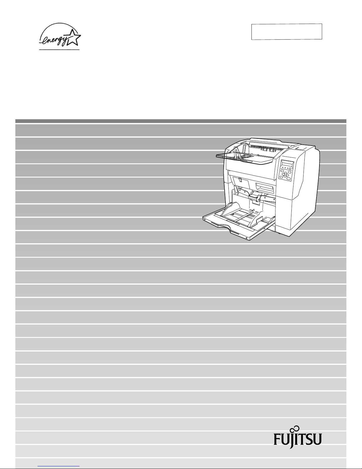
Thank you for purchasing the fi-4860C Duplex Color Scanner.
The fi-4860C is an image scanner designed to scan various documents in large
quantities. FUJITSU fi series image scanners are known for its high reliability and
this scaner is no exceptions. The fi-4860C is designed to give you the best results
for your scnning need.
The fi-4860C has the following features.
High speed, high quality color scanning capabilities
Scans documents of A4 size at the speed of 60ppm/120ipm (200dpi).
Highly reliable document handling
Accepts various thicknesses, sizes and types of documents.
Production ready
High capacity hopper (500sheets, 20lb(75g/m2) A4 size) and imprinter
options. Duplex capability is provided as standard.
About this manual
The manual provides the following information.
1. BASIC OPERATIONS
This chapter describes basic scanner operations and basic document
scanning.
2. SCANNING DOCUMENTS
This chapter describes how to scan various type of documents.
3. DAILY CARE
This chapter describes how to clean the scanner.
4. REPLACING CONSUMABLES
This chapter describes how to replace scanner consumables.
5. SOLVING COMMON PROBLEMS
INTRODUCTION
Page 3

●ii
This chapter describes how to remedy document jams, other trouble,
items to check before contacting the agent where you bought the
scanner, and how to check device labels.
6. ADF DOCUMENT SPECIFICATIONST
This chapter describes about documents can be used with this scanner.
7. OPERATOR PANEL MENUS
This chapter describes about Setup-mode and Test-mode.
8. OPTIONS
This chapter describes about options.
9. SCANNER SPECIFICATIONS
This chapter lists the scanner specifications.
The “Installation Guide” is attached to this Scanner.
This guide icontains necessary information for the scanner and the driver
installation, please also read the Installation Guide.
1. SCANNER BASICS
This chapter describes how to prepare the scanner for use.
2. INSTALLATION AND CONNECTIONS
This chapter describes how to install and connect the scanner, and how
to install the scanner application.
We hope that this manual is useful in taking full advantage of the fi-4860C Duplex
Color Scanner's features.
August, 2002
Page 4

●iii
■ Revisions
FCC declaration
This equipment has been tested and found to comply with the limits for a Class B
digital device, pursuant to Part 15 of the FCC Rules. These limits are designed to
provide reasonable protection against harmful interference in a residential
installation. This equipment generates, uses, and can radiate radio frequency
energy and, if not installed and used in accordance with the instruction manual, may
cause harmful interference to radio communications. However, there is no
guarantee that interference will not occur in a particular installation. If this
equipment does cause harmful interference to radio or television reception, which
can be determined by turning the equipment off and on, the user is encouraged to
try to correct the interference by one or more of the following measures:
• Reorient or relocate the receiving antenna.
• Increase the separation between the equipment and receiver.
• Connect the equipment into an outlet on a circuit different from that to which the
receiver is connected.
• Consult the dealer or an experienced radio/TV technician for help.
This Class B digital apparatus complies with Canadian ICES-003.
Cet appareil numérique de la classe B est conformme à la norme NMB-003 du
Canada.
CAUTION
Changes or modifications not expressly
approved by the party responsible for compliance could void the user’s authority to operate
the equipment.
WARNING
• The use of a non-shielded interface cable
with the referenced device is prohibited.
The length of the parallel interface cable
must be 3 meters (10 feet) or less. The
length of the serial interface cable must be
15 meters (50 feet) or less.
• The length of the AC cable must be 3
meters (10 feet) or less.
Page 5

●iv
Bescheimigung des Herstellers / Importeurs
Hiermit wird bescheinigt, daß der/dieldas
• fi-4120C in Übereinsstimmung mit den Bestimmungen der
• AmtsblVfg 243/1991 funkentstört ist. Der Deutschen Bundesport wurde das
Inverkehrbringen dieses Gerätes angezeigt und die Berechtigung zur Überprüfung
der Serie auf Einhaltung der Bestimmungen eingeräumt.
• Maschinenlärminformationsverordnung 3. GS GV, 18.01.1991:Der höchste
Schalldruckpegel beträgt 70 dB (A) order weniger gemäß ISO/7779.
Page 6

●v
International Energy Star Program
As a participating operator of the International Energy Star Program,
PFU LIMITED. certifies that this product satisfies the requirements
of the International Energy Star Program.
The International Energy Star Program is an international program
for promoting energy conservation in computers and other office equipment. The
purpose of this program is to promote the development and propagation of products
provided with functions for efficiently limiting energy consumption. Operators opt to
participate in this program on a voluntary basis. Equipment covered by this program
are computers, displays, printers, facsimiles, copiers, and other office equipment.
The standards for each of these equipment Energy Star mark ( ) are unified by
each participating country.
Use in High-safety Applications
This product has been designed and manufactured on the assumption that it will be
used in office, personal, domestic, regular industrial, and general-purpose
applications. It has not been designed and manufactured for use in applications
(simply called "high-safety applications" from here on) that directly involve serious
danger to life and health when an extremely high degree of safety is required, for
example, in the control of nuclear reactions at nuclear power facilities, automatic
flight control of aircraft, air traffic control, operation control in mass-transport
systems, medical equipment for sustaining life, and missile firing control in weapons
systems, and when provisionally the safety in question is not ensured. The user
should use this product without adopting measures for ensuring safety in such highsafety applications. FPU Co., Ltd. assumes no liability whatsoever for damages
arising from use of this product by the user in high-safety applications, and for any
claims or compensation for damages by the user or a third party.
Page 7

●vi
About the use of mercury
Scanner lamp includes mercury.
Too avoid unexpected injury, read the followings carefully.
Doing following actions may result in serious personal injuries:
• Put the substance in the lamp into mouth as it contains mercury.
• Vaporize, crumb, condense the scanner.
• Aspirate the chemical liquid containd in scanner parts.
Dispose of the scanner should be conducted as required by local ordinances or
regulations.
Illegal Copying
Copying of bank notes, currency, government-issued bonds and passports, licenses
and permits issued by public and private organizations, official documents, private
documents, etc. is illegal and punishable by law.
Copyright
Copyright items such as books, paintings, wood block prints, maps, drawings,
photographs, etc. cannot be reproduced without the permission of the rightful
person except in individual or domestic applications, or in other similar applications
within a limited scope.
Page 8

●vii
Trademarks
Microsoft®, Windows® and Windows NT® are registered trademarks of Microsoft
Corporation of the USA and other respective countries.
ISIS
®
is a registered trademark of Pixel Translations, A Division of Actionpoint Inc.
Adobe and the Adobe logo as well as Acrobat and the Acrobat Logo are trademarks
of Adobe Systems Incorporated.
Other product names referred to in this manual are registered trademarks or
trademarks of respective companies.
How Trademarks Are Indicated In This Manual
References to operating systems (OS) are indicated as follows:
Windows® 95: Refers to Microsoft® Windows® 98 operating system.
Windows® 98: Refers to Microsoft® Windows® 98 operating system.
Windows® Me: Refers to Refers to Microsoft® Windows® Millennium Edition
operating system.
Windows® 2000: Refers to Microsoft® Windows® 2000 Professional operating
system.
Windows
®
XP: Refers to Microsoft® Windows® XP Professional operating
system, and Microsoft
®
Windows® XP Home Edition operating
system.
Windows NT®: Refers to Microsoft® Windows NT® operating system Version4.0.
Where there is no distinction between the different versions of the above operating
system, the general term "Windows® " is used.
All Rights Reserved, Copyright© PFU LIMITED 2002.
Page 9

●viii
■ Preface
Safety Precautions
This manual describes important details for ensuring the safe and correct use of
this product. Thoroughly read this manual before you start to use this product. In
particular, be sure to read and fully understand the Safety Precautions described in
this manual before you use this product.
Also, store this manual in a safe place so that it can be easily referred to during use
of this product.
Warning Indications Used In This Manual
This manual uses the following indications to ensure safe and correct use of this
product, and to prevent possible danger and injury to the operator and other
persons.
CAUTION
This indication alerts operators to an operation that, if not strictly observed, may result in
severe injury or death.
WARNING
This indication alerts operators to an operation that, if not strictly observed, may result in
safety hazards to personnel or damage to
equipment.
Page 10

●ix
Symbols Used In This Manual
This manual uses the following symbols in explanations in addition to warning
indications.
ATTENTION
This symbol alerts operators to particularly
important information. Be sure to read this information.
HINT
This symbol alerts operators to helpful advice
regarding operation.
A TRIANGLE symbol indicates that special care
and attention is required.
The drawing inside the triangle shows the specific
caution.
A CIRCLE with a diagonal line inside shows
action which users are not
allowed to do.The drawing inside or under the circle shows the specific
action that is not allowed.
R
Outline characters on a colored background
shows instructions users
should follow. It may include the drawing which
shows the sepecific
instruction.
Page 11

●x
Screen Examples In This Manual
The screen examples in this manual are subject to change without notice in the
interest of product improvement.
If the actual displayed screen differs from the screen examples in this manual,
operate by following the actual displayed screen referring to the User's Manual of
the scanner application you are using.
Furthermore, the screenshots in this manual are for the FUJITSU TWAIN32
scanner driver and the Image Capturing Software Utilities "ScandAll 21" for
Microsoft® Windows®.
Page 12
●xi
■ Safety Precautions
WARNING
The following describes important warnings described in this manual.
Do not touch the AC cable with wet hands.
Do not damage the AC cable.
Use only specified AC cables and connector cables
Do not insert or disconnect the power plug with wet
hands. Doing so might cause electric shock.
A damaged AC cable might cause fire or electric
shock.
Do not place heavy objects on AC cables, or pull,
bend, twist, heat, damage or modify AC cables.
Also, do not use damaged AC cables or power
plugs, and AC cables or power plugs when the
power outlet fitting is loose.
Use only specified AC cables and connector cables.
Failure to use the included so might cause electric
shock and equipment failure.
Page 13

●xii
Use this scanner only at the indicated power voltage. Do not connect
to multiple-power strips.
Wipe any dust from the power plug.
Do not install in locations subject to oil smoke, steam, humidity, and
dust.
Do not use the scanner if you smell strange odor.
Use this scanner only at the indicated power
voltage. Improper power voltage so might cause fire
or electric shock.
Also, do not connect to multiple-power strips.
Wipe off any dust from metal parts on the power plug
or metal fittings with a soft, dry cloth. Accumulated
dust might cause fire or electric shock.
Do not install the scanner in locations subject to oil
smoke, steam, humidity, and dust. Doing so might
cause fire or electric shock.
If you sense heat coming from devices or detect
other malfunctions such as smoke, strange smells or
strange noises, immediately press down the power
button to turn off the scanner and then disconnect its
power plug.
Make sure that the smoke has disappeared, and
then contact the agent where you bought the
scanner.
Page 14

●xiii
Turn the scanner OFF if it is damaged.
Do not allow liquids to get inside the scanner.
If the scanner is damaged for any reason, press
down the power button the scanner and unplug the
power cable before contacting the authorized agent.
Do not insert or drop foreign metal objects in to the
scanner.
Do not scan wet document or document with paper
clips.
Do not splash or allow the scanner to get wet.
If foreign objects (water, small metal objects, liquids,
etc.) get inside the scanner, immediately press down
the power button to turn off the scanner and disconnect the power plug from the power outlet.
Then contact the agent where you bought the scanner or Maintenance Service Center.
Pay particular attention to this warning in households where there are small children.
Page 15

●xiv
Do not touch the inside of the scanner unless necessary.
CAUTION
The following describes important cautions described in this manual.
Do not install the scanner on unstable surfaces.
Firmly insert the power plug.
Do not disassemble or modify the scanner. The
inside of the scanner contains high-voltage
components. Touching these components might
cause fire or electric shock.
Install the scanner on a desk so that none of its parts
protrude outside of the desktop. Also, make sure
that the scanner is installed on a flat, level surface.
Do not install the scanner on unstable surfaces.
Install the scanner on a level surface that is free of
vibration to prevent it from tilting.
Firmly insert the power plug into the power outlet as
far it can go.
Page 16

●xv
Do not block the ventilation ports.
Do not place heavy objects or climb on top of the scanner.
Before moving the scanner, disconnect the power plug from the power
outlet.
Protect the scanner from static electricity.
Do not block the ventilation ports. Blocking the
ventilation ports generates heat inside of scanner,
resulting in fire or scanner failure.
Do not place heavy objects on the scanner or use
the scanner's top surface for performing other work.
Improper installation might cause injuries.
Do not move the scanner with the power and
interface cables connected as this might damage the
cables, causing fire, electric shock or injuries.
Before moving the scanner, be sure to disconnect
the power plug from the power outlet, and
disconnect connector cables. Also, make sure that
the floor is free of obstructions.
Install the scanner away from strong magnetic fields
and other sources of noise. Also, protect the
scanner from static electricity as this might cause the
scanner to malfunction.
Page 17

●xvi
Do not use aerosol sprays near the scanner.
Avoid any contact when scanner is in use.
Disconnect the power plug from the power outlet when the scanner is
not used for a long period of time.
Do not install the scanner in the direct sunlight.
Do not use aerosol sprays, for example, to clean the
scanner. Air sprayed from aerosol sprays causes dirt
and dust to enter the scanner, resulting scanner
failure and malfunction.
Avoid any contact when scanner is operating as this
may cause injuries.
When the scanner is not used for a long period of
time, be sure to disconnect the power plug from the
power outlet for safety's sake.
Do not install the scanner in the direct sunlight or
near heating apparatus. Doing so might cause heat
to build up inside the scanner, causing fire or
scanner trouble. Install the scanner in a wellventilated location.
Page 18

●xvii
Do not carry out alone.
When you carry the scanner, never carry out alone.
Page 19

●xviii
■ Fujitsu Group Offices
Please send your comments on this manual or on Fujitsu products to the following
addresses:
FUJITSU COMPUTER PRODUCTS OF
AMERICA, INC.
2904 Orchard Parkway, San Jose, CA
95134-2009, U.S.A.
Phone: (1-800)591-5924;
(1-408)432-6333
Technical Assistance Center:
(1-800)626-4686
Fax: (1-408)894-1709
Website: http://www.fcpa.com/
E-mail: info@fcpa.fujitsu.com
FUJITSU CANADA, INC.
2800 Matheson Boulevard East,
Mississauga, Ontario L4W 4X5, Canada
Phone: (1-905)602-5454
Fax: (1-905)602-5457
Website: http://www.fujitsu.ca/
E-mail: imaging@fujitsu.ca
(For Sales Questions)
scantech@fujitsu.ca
(For technical questions)
FUJITSU EUROPE LTD.
Hayes Park Central, Hayes End Road,
Hayes Middlesex UB4 8FE, U.K.
Phone: (44-208)573-4444
Fax: (44-208)573-2643
Website: http://www.fujitsueurope.com/
E-mail: iwebmaster@fujitsu-europe.com
FUJITSU DEUTSCHLAND GMBH.
Frankfurter Ring 211, 80807 München
40, Germany
Phone: (49-89)323-78-0
Fax: (49-89)323-78-100
Website: http://de.fujitsu.com/
E-mail: webmaster@fujitsu.de
FUJITSU ITALIA S.p.A.
Via Nazario Sauro, 38
20099 Sesto San Giovanni (Milan), Italy
Phone: (39-02)26294-1
Fax: (39-02)26294-201
Website: http://www.fujitsu-europe.com/
FUJITSU ICL ESPAÑA, S.A.
Camino Cerro de los Gamos, 1 28224,
Pozuelo de Alarcon, Madrid, Spain
Phone: (34-91)784-9000
Fax: (34-91)784-9379
Website: http://www.fujitsu-europe.com/
E-mail: imagemaster@mail.fujitsu.es
FUJITSU AUSTRALIA LTD.
Fujitsu House 2 Julius Avenue
North Ryde, N.S.W 2113 Australia
Phone: (61-2)9776-4555
Fax: (61-2)9776-4019
Website: http://au.fujitsu.com/
FUJITSU ASIA PTE.LTD.
20 Science Park Road, #03-01, Tele
Teck Park Singapore Science Park II,
Singapore 117674
Phone: (65)777-6577
Fax: (65)771-5499
Website: http://sg.fujitsu.com/
E-mail: inquiry@fcsl.fujitsu.com.sg
Page 20

●xix
FUJITSU TAIWAN LTD.
19th Fl., No39, Sec.1,Chung-hwa Rd.,
Taipei, Taiwan R.O.C.
Phone: (886-2)2311-2255
Fax: (886-2)2311-2277
Website: http://tw.fujitsu.com/
FUJITSU HONG KONG LTD.
10/F., Lincoln House, 979 King's Road,
Taikoo Place, Island East, Hong Kong
Phone: (852)2827-5780
Fax: (852)2827-4724
Website: http://hk.fujitsu.com/
E-mail: scanner@fujitsu.com.hk
FUJITSU SYSTEMS BUSINESS
(THAILAND) LTD.
12th Fl., Olympia Thai Tower, 444
Rachadapisek Road, Samsennok,
Huay kwang, Bangkok 10320, Thailand
Phone: (662)512-6066
Fax: (662)512-6068
Website: http://th.fujitsu.com/
FUJITSU KOREA LTD.
5-11 Fl., Coryo Finance Center Building,
Youido-Dong 23-6, Young DungPo-gu,
Seoul, Korea, 150-010
Phone: (82-2)3787-6159
Fax: (82-2)3787-6164
Website: http://kr.fujitsu.com/
E-mail: webmaster@fkl.fujitsu.co.kr
FUJITSU MALAYSIA SDN.BHD.
7th FL., Wisma Damansara, Jalan
Semantan 50490 Kuala Lumpur,
MALAYSIA
Phone: (60-3)254-3644
Fax: (60-3)253-3940
Website: http://my.fujitsu.com/
FUJITSU PHILIPPINES, INC
2nd Fl., United Life Building, Pasay
Road, Legaspi Village Makati,
Metro Manila, Philippines
Phone: (63-2)812-4002
Fax: (63-2)817-7576
Imaging Products Division,
PFU LIMITED
Solid Square East Tower, 580 Horikawacho, Saiwai-ku, Kawasaki-shi,
Kanagawa 212-8563, Japan
Phone: (81-44)540-4658
Fax: (81-44)540-4639
Website: http://
imagescanner.fujitsu.com/
E-mail: scanners@pfu.fujitsu.com
PFU LIMITED
(Corporate headquarters)
Nu 98-2 Unoke, Unoke-machi,
kahoku-gun, Ishikawa 929-1192, Japan
Phone: (81-76)283-1212
Fax: (81-76)283-4689
Page 21

●xx
Page 22

xxi
1 BASIC SCANNER OPERATIONS .......................... 1
Turning the Scanner ON ....................................................................2
Waking up the Scanner from the Power Save Mode .........................5
Basic Operation of the Operator Panel ..............................................6
Setting the Stacker ..........................................................................13
Setting the Stacker Extension .........................................................15
Loading Documents on the Hopper .................................................16
Inserting Documents Manually ........................................................19
Scanning Documents ......................................................................21
2 SCANNING VARIOUS TYPES OF DOCUMENTS 25
Scanning Different-size Documents ................................................26
Saving Scanned Images in PDF Format .........................................27
Removing a Color from Scanned Image (dropout color) .................32
3 DAIRY CARE ........................................................ 35
Cleaning Materials and Areas Requiring Cleaning ..........................36
Cleaning the Pad .............................................................................39
Cleaning the Rollers ........................................................................42
Cleaning the Transport Path ............................................................58
Cleaning the Discharge Brush .........................................................60
Cleaning the Glass Surface .............................................................65
Cleaning the Sensors ......................................................................71
Cleaning the Lamps .......................................................................77
4 REPLACEMENT OF CONSUMABLES ................ 85
Consumables and Replacement Cycle ...........................................86
How to check the Consumable Counter ..........................................87
Replacing the Pad ASSY ................................................................88
Replacing the Pick Roller Unit .........................................................93
Replacing the Brake Roller Unit ......................................................95
Replacing the Front-side Lamp .......................................................98
Replacing the Back-side Lamp ......................................................103
5 SOLVING COMMON PROBLEMS ..................... 107
Clearing Document Jams ..............................................................108
Troubleshooting .............................................................................115
CONTENTS
Page 23

xxii
Before Contacting a Service Provider ...........................................138
Labels on the Scanner ..................................................................141
6 ADF DOCUMENT SPECIFICATIONS ................ 143
Document Size ..............................................................................144
Document Quality ..........................................................................145
Hole-punching Prohibited Areas ....................................................148
Print Prohibited Area .....................................................................149
Grounding Color Areas ..................................................................150
Job Separation Sheet ....................................................................151
7 SETUP MODE ..................................................... 153
Setup Mode ...................................................................................154
Test Mode .....................................................................................213
8 OPTIONS............................................................. 231
Options ..........................................................................................232
fi-486PRFR (Front side imprinter) .................................................233
fi-486PRRE (Rear side imprinter) ..................................................234
9 SCANNER SPECIFICATIONS............................ 235
Basic Product Specifications .........................................................236
Installation Specifications ..............................................................237
Dimensions ....................................................................................239
Appendix 1 Drop-Out Color ............................................ AP-1
Appendix 2 Double-feed Detection Conditions............. AP-2
Appendix 3 Messages of Operator Panel ...................... AP-4
INDEX ..................................................................................IN-1
Page 24

1
1 BASIC SCANNER
OPERATIONS
This chapter describes basic scanner operations.
This chapter explains operations using the screens of Windows® XP.
Depending on the OS, your PC's screen shots and the operation may
be different from this manual. Please be aware that when FUJITSU
TWAIN 32 scanner data source is updated, the screens and
operations noted in this chapter may be changed slightly. In such
case, please refer to the User's Guide provided with the update.
1.1 Turning the Scanner ON .......................................................2
1.2 Waking up the Scanner from the Power Save Mode ..........5
1.3 Basic Operations of the Operator Panel .............................6
1.4 Setting the Hopper ..............................................................13
1.5 Setting the Stacker..............................................................14
1.6 Setting the Stacker Extension............................................16
1.7 Loading Documents on the Hopper...................................17
1.8 Inserting Documents Manually ..........................................20
1.9 Scanning Documents..........................................................22
Page 25
2
1.1 Turning the Scanner ON
1.1 Turning the Scanner ON
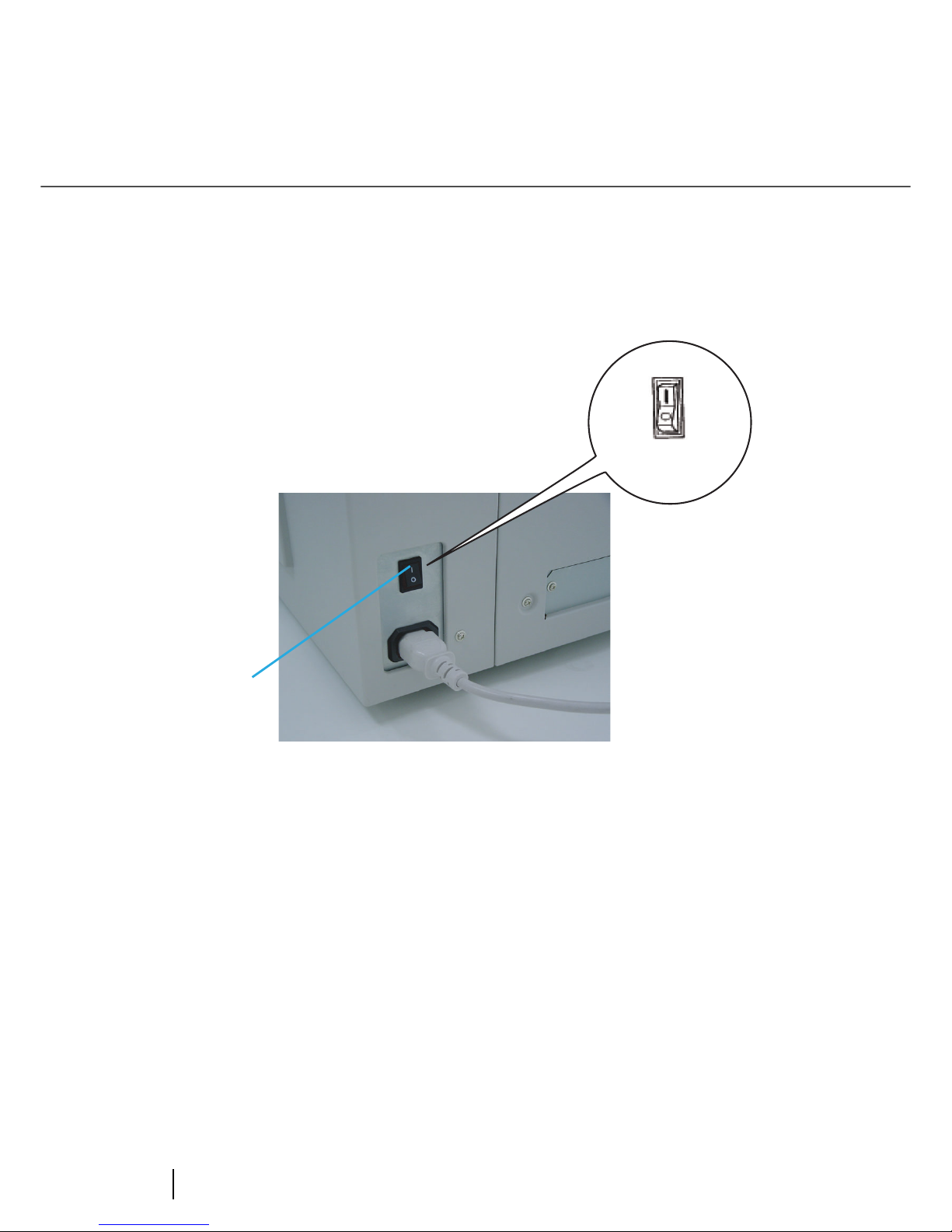
■ Turning the power on
1. Press "I" side of the main line switch located on the back of the scanner.
Main line
switch
(Rear View)
Power On
Page 26

3
1.1 Turning the Scanner ON
1
BASIC SCANNER OPERATIONS
2. Press the power button on the operator panel
The power turns on and the green Power LED at the operator panel lights.
Operator panel LCD shows "Ready" to indicate the scanner is in the READY state.
Power Button
Page 27

4
1.1 Turning the Scanner ON
■ Turning the Power off
1. Press and hold down the Power button for two seconds or longer.
2. Press "O" side of the main line switch located on the back of the scanner.
Main line
switch
(Rear View)
Power Off
Page 28

5
1.2 Waking up the Scanner from the Power Save Mode
1
BASIC SCANNER OPERATIONS
1.2 Waking up the Scanner from the
Power Save Mode
The Power Save Mode keeps the scanner in a low powered state.
If no operation is performed on the scanner for a while (15 minutes to 60 minutes depending on
the timer setup), the scanner automatically switches to the Power Save Mode.
In the Power Save Mode, the operator panel LCD display goes out. The green LED stays lit.
To wake up the scanner from the Power Save Mode, perform one of the following:
- Load documents on the hopper
- Press a button, except Power button, on the operator panel
- Send a command from the PC
Page 29

6
1.3 Basic Operations of the Operator Panel
1.3 Basic Operations of the Operator
Panel
This basic operation include how to enter setup mode and test mode.
■ Clearing errors
When an user recoverable error occurs, Check LED blinks to alarm you and its error message is displayed on the LCD. Here is an example of an error message.
Press button to clear the blinking after the cause of the error is removed.
HINT
You can not clear errors with Check LED lit. They
are not user recoverable and Check LED stays lit.
e
D
u
be
l
eoFd
Page 30

7
1.3 Basic Operations of the Operator Panel
1
BASIC SCANNER OPERATIONS
■ Lifting or lowering the hopper
When the scanner has no error state (Check LED is not lit), pressing (Previous button)
lifts the hopper and pressing (Next button) lowers the hopper.
The function is valid when:
- Read LED is not lit
- The scanning operation is not in progress
- The scanner is not in test mode (excluding Single feed and Multi feed)
- The scanner is not in setup mode
The hopper stops at the pick position or at the 250-, or 500-sheet position, depending on the
hopper height adjustment in setup mode. At the pick position, the top paper of stack (the
hopper table when no paper is loaded on the hopper) is aligned to the Pick roller. At the 250sheet position, for example, the hopper table can load about 250 sheets of paper. Each time
you press (Previous button) or (Next button), the hopper lifts or lowers by one
position. By pressing (Previous button) when loading documents, the hopper lifts up to
the pick position.
CAUTION
During hopper height adjustment, do not
touch the hopper table or do not put anything on the hopper table to prevent your
fingers from getting caught.
If something is caught in the mechanism,
the scanner may be damaged.
Page 31

8
1.3 Basic Operations of the Operator Panel
■ Clearing the consumables replacement message
This scanner has the consumables counters to estimate life of the consumables. When one
of the consumables counters, a counter for the Pad ASSY, the Pick roller unit, the Brake
roller unit, the Front-side lamp or the Back-side lamp reaches the pre-set value, the LCD
shows a message that the consumable may be expired. Here is an example of error messages.
Enter setup mode. (For the details on how to enter the setup mode, refer to "Chapter 7
OPERATOR PANEL MENUS"
Keep pressing (Next button) until the LCD shows the following message.
From this screen, you can select the consumable counter to reset. For the details on how to
clear consumable counter, please refer to the section “7.3 Setup Mode Details,” “9. Abrasion
counter reset.”
btaA
r
o
ana
rm
l
i
SE
! 04 Abr asi o
C
NT
XXXX XX NO
n
ER/=T
Page 32

9
1.3 Basic Operations of the Operator Panel
1
BASIC SCANNER OPERATIONS
■ Using the setup and the test modes.
This scanner has the setup mode to customize the setup conditions, and test mode to test
the scanner offline.
There are two types of setup mode: Online setup mode that can be entered during Ready
status and Offline setup mode that can be entered only when the scanner is offline.
Available functions differ with the two modes. For the details, refer to "Chapter 7
OPERATOR PANEL MENUS"
To enter these mode, follow the instructions below:
- Online setup mode
When LCD indicates Ready status, press (Next button). The following message
appears.
Pressing (Enter button), the scanner enters Offline setup mode.
S
Meod e
S
l
c
!
et
t
e
u
pMo
de
1
Page 33

10
1.3 Basic Operations of the Operator Panel
Turning on the power
Press (Next button) Press (Previous
button)
Setup (Online)
Wa m
i
n
gpNo
ect
a
p
o
p
e
rn
r-uw!
w
!
Ej
hec
k
s
s
o
rne
n
w
o
Wa m
i
n
gpNo
r-uw!
!
C
set
o
r
hw
nop
ep
Wa m
i
n
gpNo
r-uw!
!
W
a
t
n
R
eaiIFg
i
d
y
d
a
x
x
x
x
x
x
x
xxxeR
x
y
S
Meod e
S
l
c
!
et
t
e
u
pMo
de
1
Page 34

11
1.3 Basic Operations of the Operator Panel
1
BASIC SCANNER OPERATIONS
- Offline setup mode and Online setup mode
Keep pressing Start button and turn on the power.
- To enter setup mode, press (Left arrow button) or (Right arrow button) in [<Mode
select>] screen to select [Setup] then press (Enter button).
To exit this mode, turn off the power.
Turn on the power while pressing the Start button
Setup (Online)
TEST
Wa m
i
n
gpNo
ect
a
p
o
p
e
rn
r-uw!
w
!
Ej
heck
s
s
o
rne
n
w
o
Wa m
i
n
gpNo
r-uw!
!
C
set
o
r
hw
nop
ep
Wa m
i
n
gpNo
r-uw!
!
E
DOSEL
E
<M CE
SET TSU
P
>
T
T
Page 35

12
1.3 Basic Operations of the Operator Panel
- To enter test mode, from the [<Mode select>] screen, press (Left arrow button) or
(Right arrow button) , select [Test] and press (Enter button). Please see the
following for the operator panel transition chart.
Press (Start button) or (Enter button).
To exit this mode, turn off the power.
Test mode
E
DOSEL
E
<M CE
SET TS
UP
>
T
T
T
S
EMD<T
E
>
<
>
O
Page 36

13
1.4 Setting the Hopper
1
BASIC SCANNER OPERATIONS
1.4 Setting the Hopper
Page 37

14
1.5 Setting the Stacker
1.5 Setting the Stacker
1. Open the stacker.
Stacker
Page 38

15
1.5 Setting the Stacker
1
BASIC SCANNER OPERATIONS
2. Push the opened stacker table lock into the scanner to fix it in place.
HINT
When retracting the stacker, pull out the foldable
table a little then fold it.
Push in
Page 39

16
1.6 Setting the Stacker Extension
1.6 Setting the Stacker Extension
1. Grab the center of the blue part of the stacker extension to pull it out.
HINT
Never grab the stopper and pull out the
stacker extension.
Stopper may be damaged if you pull it.
Stopper
Stacker extension
Page 40

17
1.7 Loading Documents on the Hopper
1
BASIC SCANNER OPERATIONS
1.7 Loading Documents on the Hopper
1. Straighten the edges of the documents
1) Straighten the both side edges of the documents.
2. Fan the documents
1) Take the stack of documents with thickness of 15mm to 20mm.
2) Hold both ends and bend the documents into an arch.
3) Firmly holding the document with both hands, bend back the document as follows so
that the bent section rises up in the middle of the document as follows.
4) Repeat steps 1) to 3) for a few times.
5) Rotate the document 90 degrees, and fan again.
Page 41

18
1.7 Loading Documents on the Hopper
3. Load the documents on the hopper.
Place the documents face-up on the hopper table.
4. Adjust the Side guides to the document width.
Pressing the lock lever, slide the Side guides so that they touch the document sides.
If there is a clearance between the document edges and the guides, scanned image may
get skewed.
Page 42

19
1.7 Loading Documents on the Hopper
1
BASIC SCANNER OPERATIONS
5. Start up the scanner application and scan the documents.
For the details on hose to scan using ScandAll 21, refer to the section "1.8 Scanning
Documents."
ATTENTION
- Make sure that the document stack is below the
mark inside of the Side guides.
- For loading long documents, extend the hopper
extension.
- Do not load documents consisting of different sizes.
Page 43

20
1.8 Inserting Documents Manually
1.8 Inserting Documents Manually
When the scanner is in Manual Mode, set the documents as follows.
1. Lift the Pick roller until it is held by the magnet catch. The hopper table moves up
to feed position.
2. Place documents face-up at the center of the hopper table.
CAUTION
Be careful not to get your finger or things
caught in the mechanism when the hopper table moves up.
HINT
For information on setting Manual feed timeout, refer to "Chapter 7 OPERATOR PANEL
MENUS."
Page 44

21
1.8 Inserting Documents Manually
1
BASIC SCANNER OPERATIONS
3. Set the Side guides to the width of the documents to scan. Load the documents so
that the top edge of the documents contacts to the hopper table guide plate.
Page 45

22
1.9 Scanning Documents
1.9 Scanning Documents
The following shows the procedure for scanning documents using the "ScandAll 21" application
(simply called "ScandAll 21" from here on.)
1. Load the documents on the hopper.
For details on how to load documents, refer to the section "1.6 Loading Documents on
the Hopper."
2. Adjust the stacker table to the document size.
3. Start up ScandAll 21
From [Start] menu, select [Program] - [Scanner Utility for Microsoft Windows] - [ScandAll
21]. This starts up ScandAll 21.
4. Select the scanner to use
Select [Select Source] from the [Scan] menu.
ATTENTION
- When long documents are loaded on the
hopper, extend the stacker extension.
- When short documents are loaded, adjust the
stopper length.
Page 46

23
1.9 Scanning Documents
1
BASIC SCANNER OPERATIONS
The [Select source] dialog box appears.
Select [FUJITSU fi-4860CEAdij] (WindowsNT®4.0, [FUJITSU TWAIN 32].
Then click [Select].
5. Click the [Display in scan preview screen] on the tool bar.
The [TWAINDriver] dialog box (screen for setting the scan conditions) appears.
Page 47

24
1.9 Scanning Documents
6. Set the scan resolution, document size and other scan conditions, and click the
[Scan] button.
For the details on settings in the [TWAIN Driver] dialog box, refer to the "Scanner Utility
for Microsoft® Windows® User's Guide" on the scanner driver CD-ROM."
Page 48

25
1.9 Scanning Documents
1
BASIC SCANNER OPERATIONS
The document is scanned, and an image of the document appears on the ScandAll 21
screen.
For details on scanning various documents, see "Chapter 2 SCANNING VARIOUS
TYPES OF DOCUMENTS".
For details on ScandAll 21 function and operations, refer to ScandAll 21 Help.
Page 49

26
1.9 Scanning Documents
Page 50

25
2
SCANNING VARIOUS
TYPES OF DOCUMENTS
This chapter describes how to scan various types of documents.
This chapter explains operations using the screens of Windows® XP.
Depending on the OS, your PC's screen shots and the operation may
be different from this manual. Please be aware that when FUJITSU
TWAIN 32 scanner data source is updated, the screens and
operations noted in this chapter may be changed slightly. In such
case, please refer to the User's Guide provided with the update.
2.1 Scanning Different-size Documents ..................................26
2.2 Saving Scanned Images in PDF Format............................27
2.3 Removing a Color from Scanned Image (dropout color).32
Page 51

26
2.1 Scanning Different-size Documents
2.1 Scanning Different-size Documents
When you scan a batch of documents with different sizes using ADF, you may get skewed image
from small size documents.
Scanning the documents of the same width is recommended.
The following shows the procedure to scan the batch of mixed size documents.
1. Sort the batch into the stacks of the same width documents.
2. Adjust the side guide to the width of the documents to scan.
3. Separate the job by scanning the same width document stack each time.
For the examples of how to scan the documents, please refer to the section "1.8 Scanning
Documents."
Page 52

27
2.2 Saving Scanned Images in PDF Format
2
SCANNING VARIOUS TYPES OF
2.2 Saving Scanned Images in PDF
Format
If you would like to save scanned images in PDF format, please install AdobeQ® Acrobat® 5.0 or
later on your PC.
Adobe Acrobat 5.0 can be installed from the Adobe Acrobat CD-ROM provided.
Following shows the procedure for saving scanned images in PDF format.
1. Load the documents on the hopper.
2. Start up Adobe Acrobat 5.0.
Select [Program] - [Adobe Acrobat] from the [Start] menu. This starts up Adobe Acrobat
5.0.
Page 53

28
2.2 Saving Scanned Images in PDF Format
3. Select [Import] - [Scan] in that order from the [File] menu.
[Acrobat Scan Plugin] dialog box is displayed.
Page 54

29
2.2 Saving Scanned Images in PDF Format
2
SCANNING VARIOUS TYPES OF
4. Select [FUJITSU fi-4860CEAdij] (WindowsNT®4.0, select [FUJITSU TWAIN 32]) at
[Device] and click [Scan] button.
[TWAIN driver] dialog box is displayed.
ATTENTION
・ Select [Simplex] even if you intend to do duplex
scanning.
Page 55

30
2.2 Saving Scanned Images in PDF Format
5. Set the scan resolution, document size and other scan conditions, and click the
[Scan] button.
Scanning starts, and a message appears asking if you continue scanning.
Page 56

31
2.2 Saving Scanned Images in PDF Format
2
SCANNING VARIOUS TYPES OF
6. To end scanning, click the [Demo] button.
The scanned image is displayed. Save the scanned image in Adobe Acrobat format
(PDF).
For the details on Adobe Acrobat 5.0 operations, refer to the Adobe Acrobat 5.0manual
and help.
Page 57

32
2.3 Removing a Color from Scanned Image (dropout color)
2.3 Removing a Color from Scanned
Image (dropout color)
A selected color information (primary colors: red, green, blue) can be excluded (dropped out)
from the scanned image data.
For example, if the document contains black texts in green frames, you can set the scanner to get
only the texts and eliminate the green frames.
To drop out a color, change the setting in the [TWAIN Driver] dialog box and scan.
The following shows how to change the setting of [TWAIN Driver ] dialog box.
1. Click [[Advance] button in the [TWAIN Driver] dialog box.
The [Advance] dialog box appears.
Page 58

33
2.3 Removing a Color from Scanned Image (dropout color)
2
SCANNING VARIOUS TYPES OF
2. Select the color to drop out from [Dropout Color] under [More].
For example, if the document contains black texts in green frames, you can set the
scanner to get only the texts and eliminate the green frames.
3. Click [OK] button.
[TWAIN Driver] dialog box will be redisplayed.
Page 59

34
2.3 Removing a Color from Scanned Image (dropout color)
Page 60

35
3 DAIRY CARE
This chapter describes how to clean the scanner.
3.1 Cleaning Materials and Areas Requiring Cleaning ..........36
3.2 Cleaning the Pad .................................................................39
3.3 Cleaning the Rollers............................................................42
3.4 Cleaning the Transport Path...............................................55
3.5 Cleaning the Discharge Brush ...........................................57
3.6 Cleaning the Glass Surface................................................62
3.7 Cleaning the Sensors..........................................................68
3.8 Cleaning the Lamps ............................................................74
WARNING
When you clean the scanner, turn
off the power, and unplug power
cable from the outlet.
Page 61

36
3.1 Cleaning Materials and Areas Requiring Cleaning
3.1 Cleaning Materials and Areas
Requiring Cleaning
■ Cleaning materials
* 1) Contact the FUJITSU scanner dealer where you purchased the scanner.
*2) Any lint-free cloth can be used.
Cleaning materials Part No. Remarks
Cleaning sheet CA99501-0016
(* 1)
20 sheets/pack
Cleaner F2 CA99501-0014
(* 1)
1 bottle, 100ml/bottle
Isopropyl alcohol or
Cleaner F1
CA99501-0013
(* 1)
1 bottle, 50ml/bottle
Moisten cloth with this
fluid and wipe the scanner
to clean.
Cotton swab Commercially available
one
Dry cloth Commercially available
one(* 2)
Page 62

37
3.1 Cleaning Materials and Areas Requiring Cleaning
3
DAIRY CARE
■ Cleaning Materials and Cleaning Frequency
The following shows the standard cleaning frequency for each area requiring cleaning.
Part to clean Standard Cleaning Frequency
Pad Clean every 100,000sheets
Pick roller Clean every 100,000sheets
Brake roller
Separation roller
Feed roller
Pinch roller
Paper path Clean every 200,000sheets
Discharge brush Clean every 100,000sheets
Removable sheet guide Clean every 200,000sheets
Glass sheet guide
Document width detection
sensor
Clean every 200,000sheets
SF1
SF1.5
SF2
Front-side Lamp Clean every 100,000sheets
Back-side lamp
Page 63

38
3.1 Cleaning Materials and Areas Requiring Cleaning
ATTENTION
Please clean rollers using the cleaning sheet
every 50,000 sheets.
HINT
You must clean the scanner more frequently
when the following documents are scanned.
- Documents of coated paper
- Documents with printed text or graphics
covering almost the entire surface
- Chemically treated documents such as
carbonless paper
ATTENTION
Do not use aerosol sprays to clean the scanner.
The air from the spray may cause dirt and dust
enter the scanner mechanism and result scanner
failure and malfunctions.
ATTENTION
You must clean the following area more frequently when you use fi-486PRFR or fi-486PRRF
imprinters. The imprinter ink tend to stick to the
document path.
- Removable sheet guide
- Glass sheet guide
- Feed rollers
- Pinch rollers
Page 64

39
3.2 Cleaning the Pad
3
DAIRY CARE
3.2 Cleaning the Pad
1. Pull up the lever on the right front of the Upper transport.
2. Pull the ADF release lever toward you and lift up the ADF sheet guide.
CAUTION
Make sure that the Upper transport is
locked before you put your hands inside
of the scanner .
#&(WRRGTUJGGVIWKFG
#&(TGNGCUGNGXGT
Page 65

40
3.2 Cleaning the Pad
3. Pressing down the upper part of the Guide plate with your fingers at two positions
and pull the plate toward you to remove it.
Pad ASSY
Guide plate
Page 66

41
3.2 Cleaning the Pad
3
DAIRY CARE
4. Wipe the translucent rubber part of the Pad ASSY using a cloth moistened with
cleaner F1.
5. Install the guide plate in the reverse order of the removal.You should push it down
then the installation can be done smoothly.
6. Lower the ADF upper sheet guide gently.
7. Lift the Upper transport unit a little to release the safety lock and then lower the
transport unit slowly.
Pad(cleaning area)
Pad ASSY
Guide plate
Page 67

42
3.3 Cleaning the Rollers
3.3 Cleaning the Rollers
■ Cleaning the rollers with the cleaning sheet
1. Set the Side guide for B4 size width.
2. Set the scanner in Test mode: For the details of the procedure, refer to the section
"7.5 Test Mode Details."
3. Press (Next button) to show the following screen.
4. Remove the protective paper from the cleaning sheet.
5. Place the cleaning sheet on the hopper table, aligning the left side with the hopper
guide and with the adhesive side up. Press (Start button), then the cleaning
sheet is fed.
6. When [Hopper Empty] is displayed, press (Cancel button).
02 M
l
feeudt
T
i
Page 68

43
3.3 Cleaning the Rollers
3
DAIRY CARE
7. Place the same cleaning sheet on the hopper table with adhesive side up by
aligning the right side with the hopper guide. Press (Start button), then the
cleaning sheet is fed.
8. When "Hopper Empty" is displayed, press (Cancel) button.
9. Remove the protective paper from a new cleaning sheet and place it with the
adhesive side face down.
Repeat steps 5 through 8. When the cleaning is completed turn off the power.
Page 69

44
3.3 Cleaning the Rollers
■ Cleaning the Pick Rollers and the Separation Roller
1. Pull up the lever on the right front of the Upper transport and open it.
2. While pulling the ADF lever toward you, lift up the ADF upper sheet guide.
CAUTION
Make sure that the Upper transport is
locked before you put your hands inside of
the scanner .
#&(WRRGTUJGGVIWKFG
#&(TGNGCUGNGXGT
Page 70

45
3.3 Cleaning the Rollers
3
DAIRY CARE
3. Slide the Pick roller unit leftward a little and disengage the right ring form the shaft.
4. Wipe the Pick rollers (2 positions) and the Separation roller using a cloth
moistened with cleaner F1.
Pick roller unit
Ring(hidden)
Shaft(hidden)
Pick roller unit
Ring
5GRCTCVKQPTQNNGT
Page 71

46
3.3 Cleaning the Rollers
5. Install the Pick roller unit in the reverse order of its removal.
6. Lower the ADF upper sheet guide gently.
7. Lift the Upper transport unit a little to release the safety lock and then lower the
transport unit slowly.
HINT
When attaching the Pick roller unit, its head sometimes
hang down.
In such case, lift the unit up so that you can install it at the
right position.
Incorrect installation Correct installation
Page 72

47
3.3 Cleaning the Rollers
3
DAIRY CARE
■ Cleaning the Brake roller unit
1. Pull up the lever on the right front of the Upper transport unit.
2. Pull the ADF release lever toward you and lift up the ADF sheet guide.
CAUTION
Make sure that the Upper transport is
locked before you put your hands inside of
the scanner .
#&(WRRGTUJGGVIWKFG
#&(TGNGCUGNGXGT
Page 73

48
3.3 Cleaning the Rollers
3. Pressing down the upper part of the Guide plate with your fingers at two positions
and pull the plate toward you to remove it.
4. Turn the bail of the Brake roller upward and release the lock.
Pad ASSY
Guide plate
Bail
Brake roller
Page 74

49
3.3 Cleaning the Rollers
3
DAIRY CARE
5. Pull the Brake roller toward you to remove it.
6. Wipe the Brake roller unit using a cloth moistened with cleaner F1.
Brake roller
Page 75

50
3.3 Cleaning the Rollers
7. Attach a new Pick roller unit in the reverse order of its removal. Attach the roller
unit until it locks in.
8. Install the guide plate in the reverse order of the removal. By pressing the guide
plate down, you can install it smoothly.
9. Lower the ADF upper sheet guide slowly.
10. Lift the Upper transport unit a little to release the safety lock and then lower the
transport unit slowly.
Page 76

51
3.3 Cleaning the Rollers
3
DAIRY CARE
■ Cleaning the Feed rollers
1. Pull up the lever on the right front of the Upper transport unit.
CAUTION
Make sure that the Upper transport unit is
in the locked position before reaching
inside the scanner.
Page 77

52
3.3 Cleaning the Rollers
2. Wipe the feed rollers using a cloth moistened with cleaner F2. Wipe the rollers
thoroughly. If the rollers have black build-ups, the feed reliability is affected.
3. Lift the Upper transport unit a little to release the safety lock and then lower the
transport unit slowly.
CAUTION
Use cleaner F2 only for feed rollers (made
of metal).
Metal feed roller(in 12 locations)
Page 78

53
3.3 Cleaning the Rollers
3
DAIRY CARE
■ Cleaning the Pinch rollers
1. Lift the lever located at the right to open the Upper transport unit.
CAUTION
Make sure that the Upper transport is
locked before you put your hands inside of
the scanner .
Page 79

54
3.3 Cleaning the Rollers
2. Wipe the pinch rollers using a cloth moistened with cleaner F1.
3. Lift the Upper transport unit a little to release the safety lock and then lower the
transport unit slowly.
2KPEJTQNNGTKPNQECVKQPU
Page 80

55
3.4 Cleaning the Transport Path
3
DAIRY CARE
3.4 Cleaning the Transport Path
■ Cleaning the Transport path
1. Lift the lever located at the right to open the Upper transport unit.
CAUTION
Make sure that the Upper transport unit
is locked before you put your hands
inside of the scanner.
Page 81

56
3.4 Cleaning the Transport Path
2. Wipe and clean the whole transport path using a cloth moistened with cleaner F1.
3. Lift the Upper transport unit a little to release the safety lock and then lower the
transport unit slowly.
HINT
Vacuum the transport path if there are paper
dusts in the path.
Transport path
Page 82

57
3.5 Cleaning the Discharge Brush
3
DAIRY CARE
3.5 Cleaning the Discharge Brush
1. Lift the lever located at the right to open the Upper transport unit.
CAUTION
Make sure that the Upper transport unit is
locked before you put your hands inside of
the scanner.
Page 83

58
3.5 Cleaning the Discharge Brush
2. Pull the ADF release lever toward you and lift up the ADF sheet guide.
3. Slide the Pick roller unit leftward a little and disengage the right ring form the shaft.
4. Pressing down the upper part of the guide plate with your fingers at two positions
and pull the plate toward you to remove it.
#&(WRRGTUJGGVIWKFG
#&(TGNGCUGNGXGT
Pick roller unit
Ring(hidden)
Shaft(hidden)
Page 84

59
3.5 Cleaning the Discharge Brush
3
DAIRY CARE
6. Grab and turn the bail of the Pick roller unit upward and release the lock.
Pad ASSY
Guide plate
Bail
Brake roller
Page 85

60
3.5 Cleaning the Discharge Brush
7. Pull the Brake roller unit toward you to remove it.
8. Wipe off the dust from the discharge brush. Make sure you clean the two discharge
brushes: one at the Pick roller side, the other at the Pick roller side.
Diselectric brush(for Pick roller unit)
Diselectric brush(for brakeroller)
Page 86

61
3.5 Cleaning the Discharge Brush
3
DAIRY CARE
9. Attach a new Brake roller unit in the reverse order of its removal. Make sure that
the Brake roller unit is firmly installed.
10. Install the guide plate in the reverse order of the removal. You should push it
down then the installation can be done smoothly.
11. Lower the ADF upper sheet guide slowly.
12. Lift the Upper transport unit a little to release the safety lock and then lower the
transport unit slowly.
Page 87

62
3.6 Cleaning the Glass Surface
3.6 Cleaning the Glass Surface
■ Cleaning of the removable sheet guide
1. Lift the lever located at the right to open the Upper transport unit.
CAUTION
Wait 3 minutes after turning off the
power before touching the Lamp.
CAUTION
Make sure that the Upper transport unit
is locked before you put your hands
inside of the scanner.
Page 88

63
3.6 Cleaning the Glass Surface
3
DAIRY CARE
2. Use your index fingers to catch the both ends of the removable sheet guide.
3. Lift the right side a little first.
4. Shift the sheet guide leftward while lifting it up to remove.
Removable sheet guide
Page 89

64
3.6 Cleaning the Glass Surface
5. Wipe the both sides of the glass surface using a cloth moistened with cleaner F1.
6. Attach the removable sheet guide in the reverse order of its removal.
7. Lift the Upper transport unit a little to release the safety lock and then lower the
transport unit slowly.
Page 90

65
3.6 Cleaning the Glass Surface
3
DAIRY CARE
■ Cleaning the Glass Sheet Guide
1. Lift the lever located at the right to open the Upper transport unit.
CAUTION
Wait 3 minutes after turning off the power
before touching the Lamp.
CAUTION
Make sure that the Upper transport unit is
locked before you put your hands inside of
the scanner.
Page 91

66
3.6 Cleaning the Glass Surface
2. Push down the Glass sheet guide tab toward you.
Glass sheet guide
Page 92

67
3.6 Cleaning the Glass Surface
3
DAIRY CARE
3. Wipe the Glass sheet guide using a cloth moistened with cleaner F1.
4. Lift the tab until the guide locks in. Close the Glass sheet guide. Make sure that the
metal part is fixed firmly.
5. Lift the Upper transport unit a little to release the safety lock and then lower the
transport unit slowly.
Glass sheet guide
Ta b
Page 93

68
3.7 Cleaning the Sensors
3.7 Cleaning the Sensors
■ Cleaning the document detection sensors (6
positions)
1. Lift the lever located at the right to open the Upper transport unit.
CAUTION
Make sure that the Upper transport unit
is in the locked position before reaching
inside the scanner.
Page 94

69
3.7 Cleaning the Sensors
3
DAIRY CARE
2. Pull the ADF release lever toward you and lift up the ADF sheet guide.
3. Hold the ADF sheet guide with your hand to keep it open.
4. Wipe the six sensor surfaces with a cloth moistened with cleaner F1.
5. Lower the ADF upper sheet guide gently.
6. Lift the Upper transport unit a little to release the safety lock and then lower the
transport unit slowly.
#&(WRRGTUJGGVIWKFG
#&(TGNGCUGNGXGT
Document width sensor(in 6 locations)
Page 95

70
3.7 Cleaning the Sensors
■ Cleaning SF0 sensor and SF1 sensor.
1. Lift the lever located at the right to open the Upper transport unit.
CAUTION
Make sure that the Upper transport unit is
locked before you put your hands inside of
the scanner.
Page 96

71
3.7 Cleaning the Sensors
3
DAIRY CARE
2. Pull the ADF release lever toward you and lift up the ADF sheet guide.
3. Hold the ADF sheet guide with your hand to keep it open.
4. Wipe SF0 and SF1 sensor surfaces with a cloth moistened with cleaner F1.
5. Lower the ADF upper sheet guide gently.
6. Lift the Upper transport unit a little to release the safety lock and then lower the
transport unit slowly.
#&(WRRGTUJGGVIWKFG
#&(TGNGCUGNGXGT
SF1 Sensor
SF0 Sensor
Page 97

72
3.7 Cleaning the Sensors
■ Cleaning of SF1.5 sensor and SF2 sensor
1. Lift the lever located at the right to open the Upper transport unit.
CAUTION
Make sure that the Upper transport unit is
locked before you put your hands inside of
the scanner.
Page 98

73
3.7 Cleaning the Sensors
3
DAIRY CARE
2. Wipe SF1.5 and SF2 sensor surfaces with a cloth moistened with cleaner F1.
3. Lift the Upper transport unit a little to release the safety lock and then lower the
transport unit slowly.
Page 99

74
3.8 Cleaning the Lamps
3.8 Cleaning the Lamps
■ Front-side lamp
1. Lift the lever located at the right to open the Upper transport unit.
CAUTION
Never replace the Lamp without
turning off the power.
Wait 5 minutes after turning off
the power before touching the
Lamp.
CAUTION
Make sure that the Upper transport unit
is locked before you put your hands
inside of the scanner.
Page 100

75
3.8 Cleaning the Lamps
3
DAIRY CARE
2. Pull down the Glass sheet guide tab and open the Glass sheet guide.
Glass sheet guide
 Loading...