

Page 1
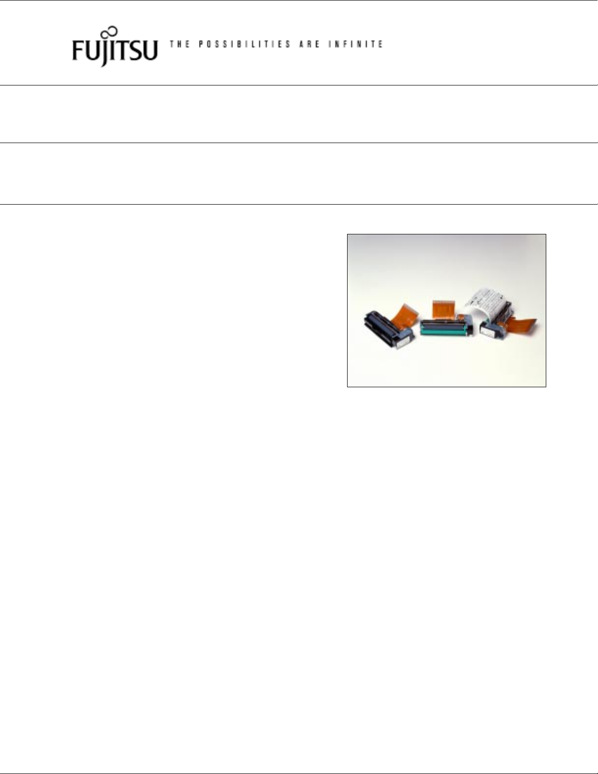
BATTERY DRIVE, 2” HIGH SPEED THERMAL PRINTER
FTP-628 Series
■ OVERVIEW
The FTP-628 MCL Series is ultra compact high speed, battery
driven thermal printer, printing on 2-inch wide paper (58mm).
Paper can be easily set by an original platen release mecha-
NOT FOR NEW
nism.
The FTP-628 MCL series can be used for a variety of
applications, such as portable terminals, POS, ticket issuing
terminals, label printers, banking terminals, and measurement
and medical equipment.
■ HIGHLIGHTS
• Ultra compact
Height 15.5 mm, width 69.9 mm, depth 35.7 mm
• High speed printing
It can print at 60 mm/s (480 dotlines/s) maximum by using
Fujitsu's unique head drive control.
DESIGN
• High resolution printing / Kanji supported
8 dots/mm of resolution printing is possible.
• Easy paper setting
Our unique platen release mechanism allows a
wide paper route even if the printer is ultra-compact, so
paper can be easily inserted. Auto loading is also available
on the MCL001 and MCL003 models.
• Two types of paper routes
Front and bottom paper feed.
• Easy mounting
Head, motor, sensor and other component wiring are unified
to one flexible cable, and the mechanism can be secured by
one hook and two screws at two locations, making mounting
easy.
1
Page 2
■ PART NUMBERS
metIrebmuNtraP
msinahcemretnirP
gnivirdrofISL101UC826-PTF
FTP-628MCL Series
hctiwsnoitcetednepodaehtuohtiwnoitresnirepaptnorf(100LCM826-PTF
hctiwsnoitcetednepodaehtuohtiwnoitresnirepapmottob(200LCM826-PTF
)bonkdnahctiwsnoitcetednepodaehhtiwnoitresnirepaptnorf(300LCM826-PTF
)hctiwsnoitcetednepodaehhtiwnoitresnirepapmottob(400LCM826-PTF
ecafretnI
draoB
ylnoKNA
ijnaK
detroppus
)elbaliavateyton(100LSD826-PTF
NOT FOR NEW
■ SPECIFICATIONS
SpecificationsItem
Part number FTP-628MCL001/002/003/004
Printing method Thermal-line dot method
Dot structure 384 dots/line
Dot pitch (Horizontal) 0.125 mm (8 dots/mm)—Dot density
Dot pitch (Vertical) 0.125 mm (8 dots/mm)—Line feed pitch
Effective printing area 48 mm
Number of columns ANK 32 columns/line (maximum 12x 24 dot font)
Paper width 58 mm
DESIGN
+0
-1
ijnaKdnayromemhsalfhtiwscinortneC/laireslasrevinU201LSD826-PTF
Paper thickness 60 to 80 µ m (some paper in this range may not be used because of
Printing Speed Maximum 60mm/sec. (480 dot line/sec.)
Character types
Character, dimensions (H×W), number of
columns
paper characteristics
Alphanumeric, katakana: 159 types
International and special characters: 195 types
JIS Kanji level 1, level 2, non-Kanji
(supported only by FTP-628DSL102): about 6800 types
12 × 24 dots, (1.5 × 3.0 mm), 32 columns: alphanumeric, katakana
24 × 24 dots, (3.0 × 3.0 mm), 16 columns: alphanumeric, katakana, Kanji
8 × 16 dots, (1.0 × 2.0 mm), 48 columns: alphanumeric, katakana
16 × 16 dots, (2.0 × 2.0 mm), 24 columns: alphanumeric, katakana, Kanji
2
Page 3
■ SPECIFICATIONS
metInoitacificepS
ecafretnI scinortneC/C232SRotsmrofnoC
FTP-628MCL Series
daehtnirproF
rewoP
ylppus
cigolroFmumixamA5.0,%5±CDV5
msinahcemretnirPnwoddaeh)HxDxW(mm5.51x3.43x6.96
snoisnemiD
draobecafretnImm42x99x131
)msinahceM(thgieW )bonktuohtiw(g35yletamixorppA
rotomrettucdnaretnirproFmumixamA1,CDV5.8-2.4
NOT FOR NEW
efildaeH
erutarepmetgnitarepO
gnitarepO
tnemnorivne
DESIGN
noitceted
noitceteD
noitcnuf
ytidimuhgnitarepO)noitasnednocon(HR%58ot02
erutarepmetegarotS)dedulcnitonrepap(C˚06+otC˚02-
ytidimuhegarotS)noitasnednocon(HR%59-5
erutarepmetdaeH
noitcetedkram/tuorepaP)sledomlla(retpurretni-otohpybdetceteD
)snoitidnocdradnats
)sselro%52:oitartnirp(
)C˚04+otC˚0taelbissopsinoitarepo
rotsimrehtybdetceteD
:oitartnirp(A)3.1(97.0,tnerrucegarevaCDV5.8-2.4
eulavkaepehtsi)().ces/mm06:deepstnirp,%5.21
ruorednu(tod/seslupnoillim001:ecnatsiseresluP
mk05ecnatsidgnilevartrepap:ecnatsisernoisarbA
,egnarecnarussaytisnedgnitnirp(C˚04+otC˚5+
noitcetedpudaeH)ylno400,300(hctiws-orcimybdetceteD
)repaPnoppiN(4E-SK05FT:repapevitisneshgiH
-)repaPnoppiN(E-SK06FT:repapdradnatS
4010P020-PTF/100UP020-PTF
-)repaPijO(R051DP
1070P020-PTF
:repapegarotsefilmuideM
repapevitisneslamrehtdednemmoceR
:repapegarotsefilgnoL
2010P020-PTF
)repaPijO(R071DP
-)repaPnoppiN(1F-SK06FT
)repaPihsibustiM(1-BBV022P
)repaPijO(H3-CB56HP
)repaPijO(N-R061DP
)repaPihsibustiM(532-PFA
3
Page 4
FTP-628MCL Series
■ FUNCTION
metImetI
.1noitcnuftnirptseT.8noitcetedytilamronbarettuC
.2noitcetedtuorepaP.9noitcnufgnivasrewoprotoM
.3noitceteddneraenrepaP.01noitcnufnoitcetedkraM
.4noitcetedpudaeH.11noitcetedytilamronbanoitarepoUCM
.5
.6noitcetedesuftuo-wolB.31noitcetorptnerruc-revorotoM
NOT FOR NEW
.7noitcetedytilamronbaegatlovdaeH.41remiterawdraH
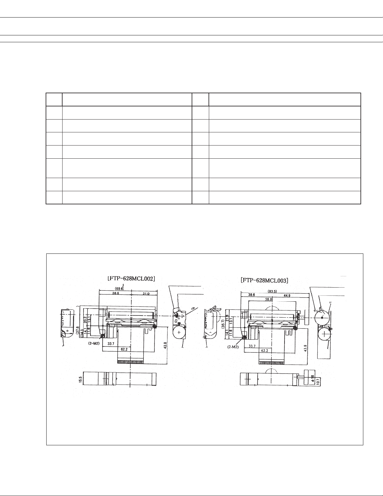
■DIMENSIONS
1. Printer mechanism
noitceted
ytilamronbaerutarepmetdaehlamrehT
.21noitcetorpecneuqesFFO/NOrewoP
DESIGN
Platen Open
Platen Close
Paper Insertions
Center of Paper
when open
Center of Paper
when close)
Platen Open
Platen Close
Paper Insertion
Unit: mm
Note: 1. Dimensions are nominal value (tolerance ±5 unless otherwise specified).
2. Platen unit (lever, platen, etc) moves by approximately 0.7mm toward paper insertion direction when platen is
open.
15.5
4
Page 5

2. Interface board
5.1
6.4
55.9
FTP-628MCL Series
130.8
83.8
4 - ø 3.6±0.1
CN6*
88.9
78.7
39.4
CN2
NOT FOR NEW
5.1
17.0
5.0
* CN6 not used
** CN8 used for paper near end detection
30.5
91.4
120.7
Part mounting side
Part solder side
DESIGN
CN1
CN3
CN8**CN7
39.4
5.1
1.6
Unit: mm
5
Page 6

FTP-628MCL Series
■ PRINTER CONNECTOR (FLEXIBLE PT BOARD) PIN ARRAYS
Control circuit side connector: 52030-3010 Molex or equivalent product (Reference CN3)
No. Signal I/O Contents No. Signal I/O Contents
1 PHK — Photo interrupter (cathode) 2 VSEN I
3 PHE O Photo interrupter (emitter) 4VH I
5VH I
7 GND —
9 LAT I Data latch 10 CLK I
11 STB6 I Enable 6 12 STB5 I
NOT FOR NEW
13 STB4 I Enable 4 14 VDD I
15 STB3 I Enable 3 16 STB 2 I
17 STB1 I Enable 1 18 TH O
19 TH O Thermistor 20 GND —
21 GND —
23 VH I
25 SW1 I Head open switch* 26 SW2 O Head open switch*
Head driving power supply
Ground for head
Ground for head
Head driving power supply
6 GNC —
8 DIN I
22 VH I
24 N.C. —
Power supply for paper sensor
Head driving power supply
Ground for head
Data input
Clock
Enable 5
Logic Power supply
Enable 2
Thermistor
Ground for head
Head driving power supply
Open terminal
DESIGN
27 MT/B I Stepping motor coil 28 MT/B I Stepping motor coil
excitation signal B excitation signal B
29 MT/A I Stepping motor coil 30 MT/A I Stepping motor coil
excitation signal A excitation signal A
* on MCL003 and MCL004 models
6
Page 7

FTP-628MCL Series
■ INTERFACE
1. Centronics interface
(1) Connector (CN2)
Connector part number : FCN-605Q030-G/M (Fujitsu Components) or equivalent
Mating connector part number : FCN-607B030-G/B (Fujitsu Components) or equivalent
(2) Connector pin assignment
No. Signal I/O Contents No. Signal I/O Contents
1 PRSTB I Data strobe 2 PRSTB-RET —
3 PRDT0 I Data 0 4 PRDT0-RET —
5 PRDT1 I Data 1 6 PRDT1-RET —
7 PRDT2 I Data 2 8 PRDT2-RET —
NOT FOR NEW
9 PRDT3 I Data 3 10 PRDT3-RET —
11 PRDT4 I Data 4 12 PRDT4-RET —
13 PRDT5 I Data 5 14 PRDT5-RET —
15 PRDT6 I Data 6 16 PRDT6-RET —
17 PRDT7 I Data 7 18 PRDT7-RET —
19 ACKNLG O Data input acknowledge 20 ACKNLG-RET —
21 BUSY O Busy 22 BUSY-RET —
23 RINF2 O Printer status 2 24 INPRM-RET —
25 SLCTIN I Printer select 26 INPRM I Reset
27 RINF1 O Printer status 1 28 RINF3 O Printer status 3
29 ATF I Paper feed request 30 GND — Logic GND
DESIGN
Connected to logic GND
Connected to logic GND
Connected to logic GND
Connected to logic GND
Connected to logic GND
Connected to logic GND
Connected to logic GND
Connected to logic GND
Connected to logic GND
Connected to logic GND
Connected to logic GND
Connected to logic GND
Notes:
• Symbol “——” means a negative logic signal.
• “–RET” signal is a return signal of the twisted pair cable.
• “I” or “O” means a signal direction from the interface board side.
(3) Connector pin number
FCN-605Q030-G/M (Fujitsu Components)
No.1
No.30
No.2
(4) Data input signal timing
PRDT0~7
PRSTB
BUSY
ACKNLG
t1 t3
t2
t4
Data set time
PRSTB pulse width
Data hold time
PRSTB to BUSY= “H”
ACKNLG pulse time
t5
:t1≥0.5 µsec
:t2≥0.5 µsec
:t3≥0.5 µsec
:t4≤0.5 µsec
:t5≈ 5.0 µsec
7
Page 8

FTP-628MCL Series
(5) Printer status signals
sutatsrorrE1FNIR2FNIR3FNIR
.1tuorepaPwoLhgiHwoL
.2dneraenrepaPhgiHhgiHwoL
.3pudaeHhgiHwoLwoL
.4ytilamronbaerutarepmetdaeHhgiHwoLhgiH
.5ytilamronbaegatlovdaeHwoLhgiHhgiH
.6ytilamronbaerawdraHhgiHhgiHhgiH
.7ytilamronbanoitcetedkraMwoLwoLwoL
.8lamroNwoLwoLhgiH
NOT FOR NEW
2. RS-232C
(1) Connector (CN7)
Connector part number : B10B-PH-K-S (J.S.T.) or equivalent
Mating connector part number : PHR-10 (J.S.T.) or equivalent
(2) Connector pin assignment
.oNlangiSO/I.oNstnetnoC.oNlangiSO/I.oNstnetnoC
1GF- dnuorgemarF2DRI atadevieceR
3DTO atadnoissimsnarT4RTDO ydaerlanimretataD
5DNG- dnuorglangiS6RSDI ydaertesataD
7NITCLSI tcelesretnirP8MRPNIIteseR
9FTAI tseuqerdeefrepaP01DWPI
Notes:
• Symbol “——” means a negative logic signal.
• “I” or “O” means a signal direction from the interface board side.
DESIGN
langis
noitallecnacnwodrewoP
8
Page 9

FTP-628MCL Series
■ CONNECTOR PIN ASSIGNMENT
1. Connector for power supply (CN1)
Part number : B6P-VH (J.S.T) or equivalent (board side)
Mating Connector : VHR-6N
.oNlangiSO/I.oNstnetnoC.oNlangiSO/I.oNstnetnoC
15V+- cigolrofylppusrewoP2DNG-dnuorG
3DNG-dnuorG4DNG-dnuorG
5HV+- rotomdaehrofylppusrewoP6HV+- rotomdaehrofylppusrewoP
2. Connector for printer mechanism connection (CN3)
NOT FOR NEW
Part number : 52030-3010 (made by Molex) or equivalent (board side)
No. Signal I/O Contents No. Signal I/O Contents
1 PHK — Photo interrupter (cathode) 2 VSEN O
3 PHE I Photo interrupter (emitter) 4VH O
5VH O
7 GND —
9 LAT O Data latch 10 CLK O
11 STB6 O Enable 6 12 STB5 O
13 STB4 O Enable 4 14 VDD O
15 STB3 O Enable 3 16 STB 2 O
17 STB1 O Enable 1 18 TH I
19 TH I Thermistor 20 GND —
21 GND —
23 VH O
DESIGN
Head driving power supply
Ground for head
Ground for head
Head driving power supply
6 GNC —
8 DIN O
22 VH O
24 N.C. —
Power supply for paper senor
Head driving power supply
Ground for head
Data input
Clock
Enable 5
Logic Power supply
Enable 2
Thermistor
Ground for head
Head driving power supply
Open terminal
25 SW1 O Head open switch* 26 SW2 I Head open switch*
27 MT/B O Stepping motor coil 28 MT/B O Stepping motor coil
excitation signal B excitation signal B
29 MT/A O Stepping motor coil 30 MT/A O Stepping motor coil
excitation signal A excitation signal A
* on MCL003 and MCL004 models
9
Page 10

■ OPTIONS
FTP-628MCL Series
emaNrebmuNtraP)mm(htgneL
elbaCecafretnI
dnadraobneewteb(
)tnempiuqe
)1NC(elbacylppusrewoP104Y226-PTF003
)2NC(scinortneCroF102Y144-PTF005
)7NC(C232SRroF103Y826-PTF005
deriuqerfi)8NC(rosnesrepapdneraeN
NOT FOR NEW
DESIGN
10
Page 11

FTP-628MCL Series
■ COMMANDS
Command Contents
HT Moves print position to the next tab.
LF Line feed.
FF Feeds forms (new page).
DC 2 Power down.
ECS RS Sets reverse printing.
ESC US Resets reverse printing.
ESC ! + n Sets print mode.
ESC %+n Download character set specification//cancellation.
NOT FOR NEW
ESC &+y+c1+c2+x+d1~dN Download character definition.
ESC *+m+n1+n2+d1~dN Sets bit image mode.
ESC ?+n External registration character deletion.
ESC 2 Sets 1/6 inch line feed length.
ESC 3+n Sets the line feed length.
ESC @ Printer initialization.
ESC A+n Sets the space between the line.
DESIGN
ESC C+n Sets the page length by character line.
ESC D+d1~dN+NUL Sets the tab position.
ESC J+n Feeds paper in forward direction and prints.
ESC K+n Reverse paper feed.
ESC R+n Selects international character.
ESC c+1+n Sets internal processing (including auto paper loading).
ESC d+n Printing and n-line feeding.
ESC e+n Prints and reverse feeds n-lines.
ECS s+n Sets printing speed.
ECS t+n Character code table selection.
ESC {+n Sets/resets upside down printing.
FS !+n Kanji printing mode collective specification.
FS & Kanji printing mode specification.
FS . Kanji printing mode cancellation.
FS 9+n Sets the detection functions.
11
Page 12

FTP-628MCL Series
Commands continued
Command Contents
FS C+n Kanji code system selection.
FS W+n Kanji double height and width mode specification/cancellation.
GS < Line feeds to the next mark.
GS A+m+n Sets the line feed length after mark detection.
GS E+n Sets print quality.
GS V+n+m Paper cutting (for pending cutter models only).
GS e+n+m Sets bar code width.
GS h+n Sets bar code height.
NOT FOR NEW
GS k+m+n+d1~dN Selects bar code type and prints.
GS w+n Sets bar code width magnification.
FS *+m+n1+n2+d1~dN High speed collective image printing specified.
GS &+m+x+y1+y2+d1~dN Registration of image data.
GS '+m+n Prints registered image data.
FS E+n Correction of impressed energy.
ESC V+n Right Rotation 90° specification / cancellation.
GS a+n Sets and cancels status transmission. (Serial Mode)
FS r+n Parameter transmission. (Serial Mode)
ESC EM+n Setting the amount of the feeding at automatic paper load.
ECS X+n+m Setting the turning time of the motor excitation.
ESC DEL+n Deletes recorded contents in flash memory.
Fujitsu Components
International
Headquarter
Offices
DESIGN
Japan
Fujitsu Component Limited
Gotanda-Chuo Building
3-5, Higashigotanda 2-chome, Shinagawa-ku
Tokyo 141, Japan
Tel: (81-3) 5449-7010
Fax: (81-3) 5449-2626
Email: promothq@ft.ed.fujitsu.com
Web: www.fcl.fujitsu.com
North and South America
Fujitsu Components America, Inc.
250 E. Caribbean Drive
Sunnyvale, CA 94089 U.S.A.
Tel: (1-408) 745-4900
Fax: (1-408) 745-4970
Email: marcom@fcai.fujitsu.com
Web: www.fcai.fujitsu.com
Europe
Fujitsu Components Europe B.V.
Diamantlaan 25
2132 WV Hoofddorp
Netherlands
Tel: (31-23) 5560910
Fax: (31-23) 5560950
Email: info@fceu.fujitsu.com
Web: www.fceu.fujitsu.com
Asia Pacific
Fujitsu Components Asia Ltd.
102E Pasir Panjang Road
#04-01 Citilink Warehouse Complex
Singapore 118529
Tel: (65) 6375-8560
Fax: (65) 6273-3021
Email: fcal@fcal.fujitsu.com
www.fcal.fujitsu.com
© 2003 Fujitsu Components America, Inc. All company and product names are trademarks or registered
trademarks of their respective owners. Rev. 04/03/2003
12
 Loading...