

Page 1
24V DRIVE INTERFACE BOARD (PARALLEL)
FTP-622DCL001/011/ FTP-622DSL001/011/012
FOR FTP-622/632/642MCL001/002/301/302/303/304
■ INTERFACE
1. Centronics
(1) Connector (CN1)
Connector part number : FCN-605Q030-G/S (Fujitsu Components)
Mating connector part number : FCN-607B030-G/D (Fujitsu Components) or equivalent
(2) Connector pin assignment
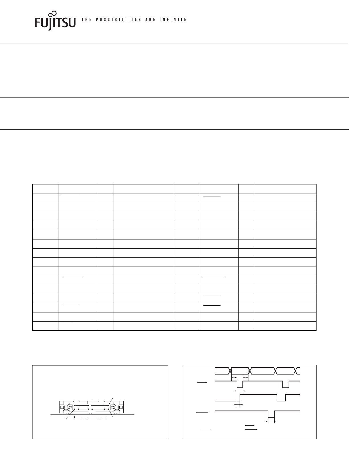
No. Signal I/O Contents No. Signal I/O Contents
1 PRSTB I Data strobe 2 PRSTB-RET —
3 PRDT0 I Data 0 4 PRDT0-RET —
5 PRDT1 I Data 1 6 PRDT1-RET —
7 PRDT2 I Data 2 8 PRDT2-RET —
9 PRDT3 I Data 3 10 PRDT3-RET —
11 PRDT4 I Data 4 12 PRDT4-RET —
13 PRDT5 I Data 5 14 PRDT5-RET —
15 PRDT6 I Data 6 16 PRDT6-RET —
17 PRDT7 I Data 7 18 PRDT7-RET —
19 ACKNLG O Data input acknowledge 20 ACKNLG-RET —
21 BUSY O Busy 22 BUSY-RET —
23 RINF2 O Printer status 24 INPRM-RET —
25 SLCTIN I Printer select 26 INPRM I Reset
27 RINF1 O Printer status 28 RINF3 O Printer status
29 ATF I Paper feed request 30 GND — Logic GND
Notes:
• Symbol “——” means a negative logic signal.
• “–RET” signal is a return signal of the twisted pair cable.
• “I” or “O” means a signal direction from the interface board side.
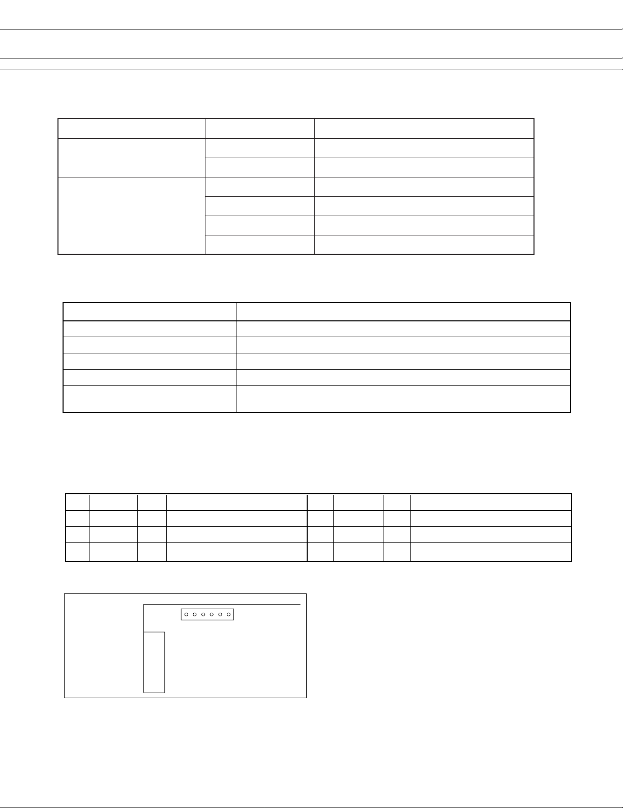
(3) Connector pin number
FCN-605Q030-G/S (Fujitsu Components) or
equivalent
No.1
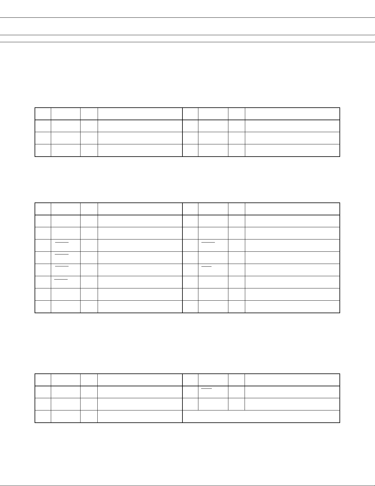
(4) Data input signal timing
PRDT0~7
t1 t3
PRSTB
BUSY
Connected to logic GND
Connected to logic GND
Connected to logic GND
Connected to logic GND
Connected to logic GND
Connected to logic GND
Connected to logic GND
Connected to logic GND
Connected to logic GND
Connected to logic GND
Connected to logic GND
Connected to logic GND
t2
t4
No.30
1
No.2
ACKNLG
Data set time
PRSTB pulse
Data hold time
:t1≥0.5 µsec
:t2≥0.5 µsec
:t3≥0.5 µsec
PRSTB to BUSY= “H”
ACKNLG pulse
t5
:t4≤0.5 µsec
.
:t5=5.0 µsec
.
Page 2
FTP-622DCL/DSL
tcudorPrebmuNtraPnoitcnuF
draoBecafretnIlellaraP
100LCD226-PTF)rettuctuohtiw(dradnatS
110LCD226-PTFlortnocrettuchtiW
100LSD226-PTF)rettuctuohtiw(dradnatS
110LSD226-PTFrellortnocrettuchtiW
draoBecafretnIlaireS
210LSD226-PTFMORHSALF+rellortnocrettuchtiW
211LSD226-PTFMORHSALF+IJNAK+rettuChtiW
■ SPECIFICATION
Item Specification
Data receive speed 19200, 9600, 4800, 1200 bps (set by dip switch)
Synchronous method Asynchronous, full duplex
Hand shake DTR/DSR signal or XON/XOFF
Input output level RS232C
Signal level
2. SERIAL INTERFACE (RS232C)
(1) Connector (CN2)
Part number : B6B-XH-A (J.S.T)
Mating connector part number : XHP-6 (J.S.T) or equivalent
(2) Pin assignment
Space (logic = 0) +3 V ~ +12 V
Mark (logic = 0) –3 V ~ –12 V
No. Signal I/O Contents No. Signal I/O Contents
1 FG — Frame GND 2 RD I Receive data
3 TD O Transmission Data 4 DTR O Data terminal ready
5 GND — Signal GND 6 DSR I Data set ready
Notes: “I” or “O” means a signal direction from the interface board side.
(3) Pin number
B6B-XH-A (J.S.T)
61
CN1
CN2
2
Page 3
FTP-622DCL/DSL
■ CONNECTOR PIN ASSIGNMENT
1. Connector for power supply (CN10)
Part number : B6P-VH (J.S.T)
Mating connector part number : VHR-6N (J.S.T) or equivalent
No. Signal I/O Contents No. Signal I/O Contents
1VCC — Power supply for logic (+5 V) 2 GND — GND (5 V, 24 V common)
3 GND — GND (5 V, 24 V common) 4 GND — GND (5 V, 24 V common)
5VDD — Power for head/motor (+24 V) 6 V DD — Power for head/motor (+24 V)
2. Connector for thermal head drive (CN8)
Part number : B16B-PH-K-S (J.S.T)
Mating connector part number : PHR-16 (J.S.T) or equivalent
No. Signal I/O Contents No. Signal I/O Contents
1 VDH O Power for head (+24 V) 2 VDH O Power for head (+24 V)
3
GND (VDH)
5 STB1 O Print enable signal 1 6 STB2 O Print enable signal 2
7 STB3 O Print enable signal 3 8 TMP I Temperature detection signal
9 STB4 O Print enable signal 4 10 LAT O Print data latch signal
11 STB5 O Print enable signal 5 12 5 VH O Power for logic (+5 V)
13 HCLK O Data transmission clock 14 HD O Print data output signal
15
GND (VDH)
— Head GND 4
— Head GND 16 VDH O Power for head (+24 V)
GND (VDH)
— Head GND
Notes:
• Symbol “——” means a negative logic signal.
• “I” or “O” means a signal direction from the interface board side.
3. Connector for Sensor (CN3)
Part number : B5B-PH-K-S (J.S.T)
No. Signal I/O Contents No. Signal I/O Contents
1 +5 V — Power for logic (+5 V) 2 PES I Paper end detect signal
3
GND (5 V)
5 HUP I Head-up detect signal
— Logic GND 4 +5 V — Power for logic (+5 V)
3
Page 4

FTP-622DCL/DSL
7. Connector for control signal input/ output (CN1)
Part number : FCN-605Q030-G/S (Fujitsu Components)
Mating connector : FCN-607B030-G/D (Fujitsu Components) or equivalent
No. Signal I/O Contents No. Signal I/O Contents
1 NC — No connection 2 NC — No connection
3 NC — No connection 4 NC — No connection
5 NC — No connection 6 NC — No connection
7 NC — No connection 8 NC — No connection
9 NC — No connection 10 NC — No connection
11 NC — No connection 12 NC — No connection
13 NC — No connection 14 NC — No connection
15 NC — No connection 16 NC — No connection
17 NC — No connection 18 NC — No connection
19 NC — No connection 20 NC — No connection
21 NC — No connection 22 NC — No connection
23 NC — No connection 24 NC — No connection
25 SLCTIN I Select signal 26 INPRM I Reset signal
27 NC — No connection 28 NC — No connection
29 ATF I Paper feed request 30 GND — GND
*Do not connect outside signal to NC.
4
Page 5

FTP-622DCL/DSL
4. Connector for paper near end detection (CN5)
Part number : B2B-PH-K-S (J.S.T)
Mating connector part number : PHR-2 (J.S.T) or equivalent
No. Signal I/O Contents No. Signal I/O Contents
1 +5 V — Power for logic (+5 V) 2 NES I Paper near end detect signal
5. Connector for stepping motor drive (CN13)
Part number : B4B-PH-K-S (J.S.T)
No. Signal I/O Contents No. Signal I/O Contents
1 MT/B O Stepping motor coil excitation 2 MT/B O Stepping motor coil excitation
3 MT/A O Stepping motor coil excitation 4 MT/A O Stepping motor coil excitation
6. Connector for cutter drive (CN11) *
Part number : B4B-EH (J.S.T)
No. Signal I/O Contents No. Signal I/O Contents
1 SW1 I Cutter position detect signal 2 GND — Logic ground
3 M+ O Motor control signal (+) 4 M- O Motor control signal (-)
*1: Only for FTP-622DCL011/111.
1
5
Page 6
FTP-622DCL/DSL
■ PRINTING COMMANDS (CENTRONICS INTERFACE)
Command Contents
HT Moves the print position to the next tab.
LF Line feed.
FF Feeds forms (new page).
ESC RS Sets reverse printing.
ESC US Resets reverse printing.
ESC ! +n Sets print mode.
ESC* +m+n1+n2+d1~dN Sets the bit image mode “m” for n1, n2 dot numbers.
ESC 2 Sets 1/6 inch line feed length.
ESC 3 + n Sets the line feed length.
ESC @ Printer initialization.
ESC A+n Sets the space between lines.
ESC C+n Sets the page length by character line.
ESC D+d1~dN+NUL Sets the tab position.
ESC J+n Feeds paper in forward direction.
ESC K+n Feeds paper in reverse direction.
ESC c+1+n Sets the internal processing.
ESC R+n Selects the international character.
ESC s+n Sets the printing speed.
ESC d+n Printing and n-line feeding.
ESC e+n Reverse line feed in “n” lines after printing.
ESC t+n Character code table selection.
ESC {+n Sets/resets the upside down printing.
ECS EM+n Automatic paper feed distance setting.
ESC X+n+m Setting turning time of the motor excitation.
ESC V+n Right Rotation 90° specification / cancellation.
ESC %+n Selects the font to download*3.
ESC &+y+c1+c2+x+d1~dn Registers the download front*3.
ESC ?+n External character registration deletion*3.
FS E+n Correction of impressed energy.
1
FS ! +n Sets the Kanji print mode*
FS & Sets Kanji mode*1.
.
(Continued)
6
Page 7

(Continued)
Command Contents
FS . Resets Kanji mode*1.
FS C+n Selects Kanji code type*1.
FS 9+n Sets the detection functions.
FS*+m+n1+n2+d1~dn Prints image data on SRAM*3.
FS r+n Notifies of printing finish*4.
FS W+n Sets/resets 4 times enlarged character.
GS < Line feeds to the next mark.
GS A+m+n Sets the line feed length after mark detection.
FTP-622DCL/DSL
GS E+n
GS V+n+m Executes paper cutting*2.
GS e+n+m Sets the bar width.
GS h+n Sets the barcode height.
GS k+m+n+d1~dN Selects the barcode type and prints.
GS w+n Sets the barcode length.
GS &+m+x+y1+y2+[d]k Registration of image data*3.
GS '+m+n Prints registered image data *3.
GS a+n Sets and cancels status transmission (valid only for DSL)*
Sets print quality
.
*1: Only for FTP-622DSL112.
*2: Only for FTP-622DCL011 or FTP-622DSL011/012.
*3: Only for FTP-622DSL012.
*4: Only for FTP-622DSL011/012.
3
.
7
Page 8

■ OPTIONS
1. Cable (With FTP-622MCL, FTP-632MCL, FTP-642MCL)
emaNrebmuNtraPhtgneLelbaC
*)8NC(elbacnoitcennocdaehlamrehT 100Y226-PTF)sehcni6.01(mm072
)1NC(scinortneC102Y226-PTF)sehcni17.91(mm005
elbacecafretnI
)2NC(laireS103Y226-PTF)sehcni17.91(mm005
)01NC(cigoldna,rotom,daehrofelbacrewoP 104Y226-PTF)sehcni8.11(mm003
noitpoelbactrohs* 100Y426-PTF)sehcni9.5(mm051
2. Paper holder
Name Part number
Flange FTP-040HF
FTP-622DCL/DSL
Stand FTP-040HS
Europe
Fujitsu Components Europe B.V.
Diamantlaan 25
2132 WV Hoofddorp
Netherlands
Tel: (31-23) 5560910
Fax: (31-23) 5560950
Email: info@fceu.fujitsu.com
Web: www.fceu.fujitsu.com
Asia Pacific
Fujitsu Components Asia Ltd.
102E Pasir Panjang Road
#04-01 Citilink Warehouse Complex
Singapore 118529
Tel: (65) 6375-8560
Fax: (65) 6273-3021
Email: fcal@fcal.fujitsu.com
www.fcal.fujitsu.com
Fujitsu Components
International
Headquarter
Offices
Japan
Fujitsu Component Limited
Gotanda-Chuo Building
3-5, Higashigotanda 2-chome, Shinagawa-ku
T okyo 141, Japan
Tel: (81-3) 5449-7010
Fax: (81-3) 5449-2626
Email: promothq@ft.ed.fujitsu.com
Web: www.fcl.fujitsu.com
North and South America
Fujitsu Components America, Inc.
250 E. Caribbean Drive
Sunnyvale, CA 94089 U.S.A.
Tel: (1-408) 745-4900
Fax: (1-408) 745-4970
Email: marcom@fcai.fujitsu.com
Web: www.fcai.fujitsu.com
© 2004 Fujitsu Components America, Inc. All company and product names are trademarks or registered
trademarks of their respective owners. Rev. 11/15/2004.
8
 Loading...