

Page 1

SERVIS KVM
Multi Platform
USB Emulation
Server Intelligent Switch for Multi Platform
For IA and UNIX servers
FS-1004MU
FS-1008MU
User’s Manual
FUJITSU COMPONENT LIMITED
050209
Page 2

limitation, general office use, personal use, household use, and ordinary industrial use, but
and manufactured as contemplated for use accompanying fatal risks or dangers that, unless extremely high safety is
secured, could lead directly to death, personal injury, severe physical damage or other loss (hereinafter "High Sa
Required Use"), including without limitation, reaction core control in nuclear power facilities, aircraft autopilot flight
control, air traffic control, operation control in mass transport control systems, medical instruments for life support
systems,
safety required for the High Safety Required Use. If you wish to use this Product for High Safety Required Use, please
consult with our sales perso
CAUTION
1) This product and document are the copyright of Fujitsu Component Limited.
Any unauthorized reprinting, copying, republishing, or modifications to this product or document is
prohibited by law.
2) The details of this product and document are subject to revision without notice.
3) If any part of this product or manual is found to be invalid or unclear, please contact our service
department.
4) We accept no responsibility for any effect this product may have on other products.
5) If this product is used in any goods or technology intended for export that come under the authority of
the “Foreign Exchange and Foreign Trade Control Law” then it is necessary to get such licenses as the
relevant laws call for at the time of export of said goods.
6) This product was not designed for purposes requiring high standards of reliability such as medical
equipment for life-support, marine transponders, or equipment for aerospace and controlling nuclear
power. If the switch device is used with any of the above equipment, facilities, or control systems, we
accept no responsibility for injuries, fires, or other damage that may be caused in the event of device
failure.
7) Do not disassemble, repair or modify this product; this product should be handled by our maintenance
crew. Violation of this may lead to unpredicted problems.
8) This product contains both metallic and plastic components. Follow the any regulations in force in your
community when disposing of this product.
9) All company names and product names referred to in this document are registered trademarks of their
respective owners.
Voluntary control of electromagnetic interference
FCC WARNING:
Changes or modifications not expressly approved by the party responsible for compliance could void the user's
authority to operate the equipment.
This equipment has been tested and found to comply with the limits for a Class B digital device, pursuant to Part 15
of the FCC Rules. These limits are designed to provide reasonable protection against harmful interference in a
residential installation.
This equipment generates, uses, and can radiate radio frequency energy and, if not installed and used in accordance
with the instruction, may cause harmful interference to radio communications. However, there is no guarantee that
interference will not occur in a particular installation. If this equipment does cause harmful interference to radio or
television reception, which can be determined by turning the equipment off and on, the user is encouraged to try to
correct the interference by one or more of the following measures:
- Reorient or relocate receiving antenna.
- Increase the separation between the equipment and receiver.
- Connect the equipment into an outlet on a circuit different from that to which the receiver is connected.
- Consult the dealer or an experienced radio/TV technician for help.
This Product is designed, developed and manufactured as contemplated for general use, including without
is not designed, developed
missile launching control in weapon systems. You shall not use this Product without securing the sufficient
n representatives in charge before such use.
1
fety
Page 3

Table of Contents
1 INTRODUCTION............................................................................................................................................3
1.1. CONVENTIONS..........................................................................................................................................3
1.2. PACKING LIST............................................................................................................................................3
1.3. SAFETY INSTRUCTIONS.........................................................................................................................4
1.4. DISPOSAL....................................................................................................................................................5
1.5. SAFETY PRECAUTIONS AND LIMITED WARRANTY INFORMATION:.......................................6
2. FEATURES.......................................................................................................................................................7
3. COMPONENT NAMES AND THEIR FUNCTIONS...................................................................................8
3.1 CONSOLE PANEL......................................................................................................................................8
3.2 REAR PANEL ..............................................................................................................................................9
3.3 DIP SWITCH SETTINGS.........................................................................................................................10
4. INSTALLATION PROCEDURE (RACK SETUP).....................................................................................12
5. SETUP.............................................................................................................................................................13
5.1. GETTING STARTED................................................................................................................................13
5.2. CONNECTING THE HOSTS (USING SINGLE SWITCH DEVICE).................................................13
5.3. CONNECTING THE HOSTS (USING CASCADED CONNECTIONS) .............................................14
6. OPERATION (HOST SELECTION) ...........................................................................................................16
6.1. HOST SELECTION BY HOST SELECTOR BUTTONS (NORMAL MODE)...................................16
6.2. HOST SELECTION BY KEYBOARD (HOT KEY MODE).................................................................16
6.2.1. HOT KEY MODE A..........................................................................................................................17
6.2.2. HOT KEY MODE B..........................................................................................................................21
6.3. SHOWING/HIDING HOST NAMES FUNCTION ....................................................................21
6.4. EDID SETTING MODE......................................................................................................................22
7. SPECIFICATIONS ........................................................................................................................................24
8. OPTIONAL ACCESSORIES (SOLD SEPARATELY)...............................................................................25
9. TROUBLESHOOTING .................................................................................................................................26
n KEY LAYOUT DIAGRAM 1 .........................................................................................................................27
n KEY LAYOUT DIAGRAM 2 .........................................................................................................................28
n APPENDIX: HOST NAME RECORD SHEETS........................................................................................29
2
Page 4

1 Introduction
Thank you for your purchase of this KVM Switch (from here on, simply referred to as the "switch device").
This switch device is usable with PC/AT compatible computers and Sun workstations (hereafter referred to
as "hosts") under multi-platform configurations. Requiring only a single master set of control devices
(monitor, keyboard and mouse), this switch device allows you to operate hosts from a single console setup.
Hosts can be selected simply via the select switches, keyboard or using the on screen display (OSD).
Safety instructions are provided to ensure the safe use of the switch device.
Also, be sure to thoroughly read this User's Manual before you start using the switch device to
ensure correct use. Be sure to keep this User's Manual in a safe place for future reference.
This user’s manual is written for 4-port and 8-port setups. Unless specifically noted, all explanations
assume an 8-port setup.
KVM Switch: Keyboard, Video, Mouse switch
1.1. Conventions
Symbols and terminology that are used in this manual are described below.
This symbol indicates the possibility of physical damage (such as damage to
CAUTION
the KVM switch) or physical injury, which may result if the KVM switch is
operated incorrectly by ignoring this symbol.
This logo indicates supplemental information, comments or hints.
l Text that is preceded by a sequence of numbers (1, 2, etc.) means that the operations must be
performed in the indicated order.
1.2. Packing list
Verify that the following items are included in the package. If any items are missing or damaged
immediately contact the place of purchase or our service department.
8-port KVM switch FS1008MU
n KVM Switch 1 pc.
n User’s Manual 1 pc.
n 19 inch rack mount and holder 1 large and 1 small set
n Assembly screws 1 set
4-port KVM switch FS1004MU
n KVM Switch 1 pc.
n User’s Manual 1 pc.
n AC Adapter 1 pc.
3
Page 5

CAUTION
1.3. Safety Instructions
Read the “Safety Instructions” before use to ensure proper use of this product. Safety Instructions contained
in this section are written for the user to avoid any damage to property or injury to self; please read the
following carefully.
l During installation and before using the KVM switch, carefully read about environmental conditions in
[Specifications] to use the KVM switch correctly.
l Moving the KVM switch from a cold environment to the installation location may cause condensation to
occur. Before using the KVM switch allow it to dry out completely and to reach the ambient temperature
of the installation location.
l Make sure that the local power supply voltage is within the acceptable range of the KVM switch. Make
sure that the rated voltage meets the specifications of this device (Refer to [Specifications] and the model
plate on this device).
l Do not connect or remove any cables during thunderstorms.
l In an emergency (such as: damage to the housing, parts or cables; or liquid or a foreign object has fallen
into the KVM switch) remove the power cable as soon as possible and contact your place of purchase or
an authorized maintenance person.
l Do not disassemble or modify the KVM switch for any purpose, which may cause electric shocks, or fire
and so on. Only licensed engineers may repair the KVM switch
l Do not pull up cable with a jerk. Be sure to hold connector when pulling up cable.
l Avoid operating the KVM switch with wet hands..
l Do not plug or unplug connectors with wet hands.
l Do not place unnecessary items, such as cups, on the top of the KVM switch.
l Verify that the power to the host is off before connecting or disconnecting any of the connectors. Also, be
sure to discharge any static electricity. Connecting or disconnecting the connectors while carrying a static
charge or while the power to the host is on may damage the host or this device. Please note that, damage
of this kind is not covered by the warranty.
l Only PC/AT compatible computers and SUN workstations can be hooked up to this device. However,
each host must be equipped with the following type of keyboard, mouse and monitor connectors. Other
specifications are not supported.
PC/AT compatible computers:
- Mini DIN 6P female (1 each for PS/2 keyboard and PS/2 mouse)
or USB A-type connector
- DB15HD female (for monitor)
SUN workstations:
- Mini DIN 8 P female (for keyboard)
or USB A type connector
- 13 W3 female or DB 15 HD male (for monitor)
*Note: a 13 W3 connector will require a monitor cable adapter.
l Connecting the host requires special optional cables (for PS/2, Sun and USB cables). The maximum
cable length is 5 meters. Use a 1.8-meter cable for cascaded connections. Please note that cables longer
than specified are not covered by the warranty.
l Use of standard equipment is recommended because special keyboards (programmable keys, wireless
or that require a special driver) and mice (wireless or that require a special driver) may not be supported /
operate.
l The keyboard connector for this switch device is a USB type or a PS/2 type (Mini DIN 6P female), but
you can connect an AT type (DIN 5P male) keyboard by using a PS/2 <-> AT adapter.
l The mouse connector for the switch device is a USB type or a PS/2 type (Mini DIN 6P female). A serial
type mouse may not be used as the console mouse.
l When using mice that have PS/2 wheels with scroll functions, the scroll function can only be used with
PC/AT compatible machines. Meaning that they do not function on Sun machines. Also, the scroll mice
4
Page 6

may fail to function properly depending on the software used.
l The PS/2 keyboard and mouse connectors are the same shape. Be sure the colors match to connect them
correctly. If they are forced in or connected incorrectly, the switch device may not only function
improperly but also may malfunction.
l USB connectors of this switch device are for keyboard or mouse only. Other USB devices does not work
at all.
l Set up the console’s keyboard and mouse with each host correctly. If they are not set correctly they will
not operate normally.
l Hook up the cables for each port to the same host. If the monitor port, keyboard port, and mouse port
numbers are wrong, you will not be able to select the host correctly.
l A DVI (Digital Video Interface) compatible display cannot be connected.
l The display monitor connected to this switch device should support multi-scan mode. And set its
resolution correctly. This switch device supports a resolution of 1600 x 1200 with a refresh rate of 75 Hz.
Also, the display may be off center after switching depending on the monitor and resolution settings.
Adjust the monitor or video card if this happens.
l Degradations in high resolution screen quality, such as ghosts or blurring, may be due to the monitor
cable or video card. Also, the screen may not display normally sometimes, depending on the particular
combination of display and video card. If this happens, try using a high grade cable or video card and
altering the connection environment.
l The monitor cable connector is a DB 15 HD type. You will need a monitor conversion connector
(available separately) to attach a Sun monitor that has a different shape connector. Make sure you
connect it in the correct orientation and use the fixing screws to hold it in place. It may cause trouble if it
is not connected properly.
l The [POWER] LED on the front panel flashes if the AC cord comes unplugged, reminding you to
reconnect it.
l Cascaded connections must be setup exclusively with our KVM switches only. You cannot make these
connections with switches produced by other manufacturers.
l A maximum of two levels of cascaded connections are allowed (including the master).
Attempting to cascade three or more levels will not work.
l When moving the KVM switch to a different location, use a box that protects the product from
bumping and shaking.
CAUTION
1.4. Disposal
This device consists of metal, plastic, electronic parts and so on. When it is disposed of, follow exactly the
relevant government regulations, instructions and so on.
5
Page 7

1.5. Safety Precautions and Limited Warranty Information:
Fujitsu’s Products are not designed for use in medical or life support appliances, devices, or systems where
malfunction of a Product can reasonably be expected to result in a personal injury. The Product is designed,
developed and manufactured as contemplated for general use, including, general office use, personal use,
household use, and ordinary industrial use, but is not for use for high risks or dangers that could reasonably
be expected to result in personal injury, or other loss including without limitation, nuclear application,
aircraft flight control, air traffic control, mass transport control, medical life support system, or missile
launch control in weapon system (“High Safety Required Use”). You should not use this Product without
securing sufficient safety required for such High Safety Required Use. Purchaser and its customers using or
selling Products for use in such applications do so at their own risk and agree to fully indemnify Fujitsu for
any damages resulting in such improper use or sale.
Fujitsu Component Limited or its affiliates (“Fujitsu”) warrants all Product against defects in materials and
workmanship for a limited period not to exceed three (3) year from the date of delivery to Fujitsu authorized
distributor or authorized system integrator (“Authorized Company”). Check with Fujitsu for such Authorized
Company. Fujitsu’s liability under this warranty is limited, at Fujitsu’s sole discretion, to repairing, or
replacing any component with new or like new components or parts, or replacing with a refurbished or
alternative product, or issuing credit for the purchase price, if paid, for such Product that was defective at the
time delivered to Purchaser, provided that Fujitsu will not be liable under this warranty unless: (i) Fujitsu is
promptly notified in writing upon the discovery of defects by Purchaser; (ii) the defective unit is returned to
Authorized Company, transportation charges prepaid by Purchaser; (iii) the defective unit is received for
adjustment no later than one year following the date on which such Products were delivered by Fujitsu to
Authorized Company; and (iv) Fujitsu’s examination of such units shall disclose, to its satisfaction, that such
defects have not been caused by misuse, neglect, improper installation, repair, alteration, accident, improper
storage or other action or inaction beyond reasonable practice for such Product. This warranty shall be
administered and returned to the party from whom Purchaser purchased Product which is an Authorized
Company.
THE WARRANTY SET FORTH IN THIS SECTION IS IN LIEU OF, AND EXCLUDES, AND EACH
PARTY HEREBY WAIVES, ANY OTHER REPRESENTATIONS, GUARANTEES AND
WARRANTIES, EXPRESS, IMPLIED OR STATUTORY, INCLUDING, WITHOUT LIMITATION, ANY
WARRANTY OF MERCHANTABILITY, OR FITNESS FOR A PARTICULAR PURPOSE. IN NO
EVENT SHALL FUJITSU BE LIABLE TO PURCHASER FOR LOSS OF PROFITS, LOSS OF USE,
COST OF SUBSTITUTE GOODS, OR CONSEQUENTIAL OR INCIDENTAL DAMAGES OF ANY
KIND BASED UPON A CLAIM FOR BREACH OF WARRANTY OR OTHERWISE. FUJITSU'S
WARRANTIES SHALL NOT BE ENLARGED, DIMINISHED, OR AFFECTED BY, AND NO
OBLIGATION OR LIABILITY SHALL ARISE OR GROW OUT OF, SELLER'S RENDERING OF
TECHNICAL ADVICE OR SERVICE IN CONNECTION WITH BUYER'S ORDER OR THE
PRODUCTS FURNISHED HEREUNDER.
6
Page 8

2. Features
l By connecting several hosts (PC/AT compatible computers or Sun workstations) to this switch
device, you can save a lot of space by using only one common master console rather than the
situation of a console (monitor, keyboard and mouse) for each host that was previously required.
However, you cannot hook up both a PS2 keyboard and mouse and a USB keyboard and
mouse at the same time to the console.
l All of the Host ports on this device can use PS/2 interface, USB interface and Sun serial
interface. Choose the cables to match the environment you are using.
l With a single switch device, you can attach up to four or eight hosts. (By using four or eight port
switch devices.)
l It is possible to attach more hosts by using cascaded connections.
Example: By using nine “8-port switch devices”, it is possible to hook up 64 hosts.
l The switch device can be stored in a 19 inch EIAJ standard rack cabinet in a space that is just
1U high.
l The console panel and the rear panel can be removed when putting together the rack cabinet
making it easier to connect hosts in the small area in the cabinet. (8 port switch devices)
l There is a power and voltage monitoring circuit built in to the device to let you know if the AC
cord becomes disconnected or the internal fuse blows.
l Both PS/2 and USB keyboards are supported.
l Both PS/2 and USB mice are supported.
The following PS/2 mice are supported; 2/3 button mice, each type of wheel mice (Microsoft
IntelliMouse, Microsoft IntelliMouse Explorer, Logitech/Logicool MouseMan Wheel and others) .
l A maximum monitor resolution is 1600 x 1200 and a refresh rate 75 Hz.
l Host selection is easy with the Host Selector Button or the OSD display (Hot Key Mode).
l In Hot Key Mode, you can switch hosts using the OSD (on screen display).
l OSD control can be done with Hot Keys from the keyboard. You can set three different types of
Hot Key (Ctrl+Alt+Shift, Ctrl x2, and Scroll Lock x2). This allows you to avoid key conflict
problems when applications use the same key as Hot Keys for a more effective way to use Hot
Keys.
l Auto scan automatically cycles through all of the connected hosts that are currently running,
allowing the operating status of each host to be periodically checked. The speed at which auto
scan cycles can be controlled by using the keyboard to select one of the six available switching
intervals (3 – 60 seconds).
l Auto scan can be done with the Auto Scan Button or the Hot Key Mode.
7
Page 9
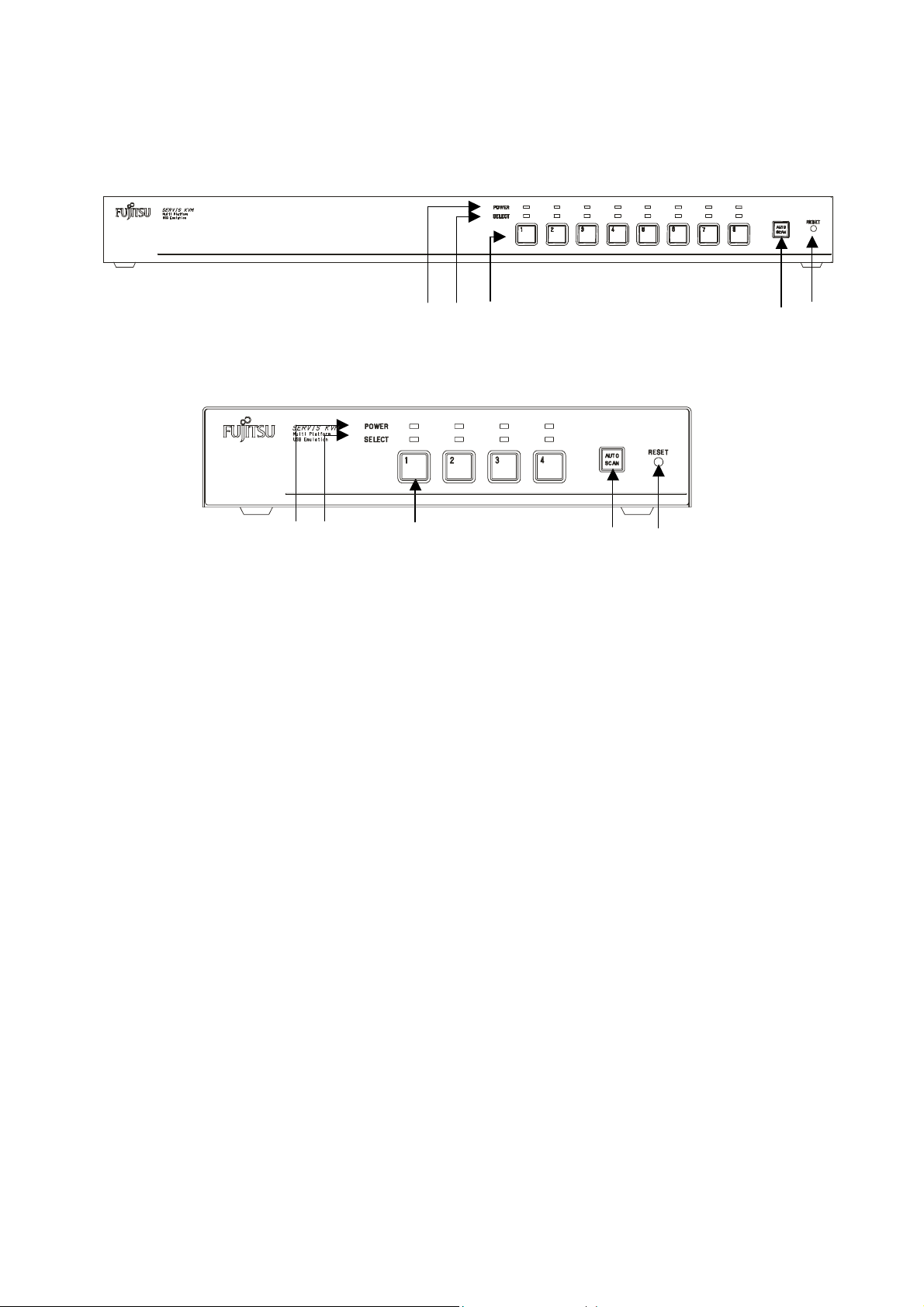
3. Component Names and Their Functions
3.1 Console Panel
1) 4) 3) 2) 5)
8 Port Console Panel
1) 4) 3) 2) 5)
4 Port Console Panel
1) POWER LED
Lights up when the host is ON. And, flashes when internal power is low by disconnect
an AC cord or blow an internal fuse.
2) Auto Scan Button
Press this button when you want to automatically switch between host screens.
Pressing it twice stops auto scan. The SELECT LEDs flash (slowly) in order during auto
scan. Also, host operations cannot be performed at this time.
3) Host Selector Buttons
Press a button to select its host. You can select hosts even if the POWER LED is not lit.
4) Select LED
Lights up when the host is selected. It flashes quickly when in the hot key mode.
5) Reset Switch
Normally, this switch is not used. Use this switch when selection is not possible or when
the keyboard or mouse cannot be operated. Press it lightly with the tip of a metal pin or
similar. Pressing this switch returns the switch device to its initial state, and hosts can
be restored without being rebooted. If you are using USB or Sun serial interfaces, you
can reset the interface by holding the reset switch down for over five seconds.
8
Page 10
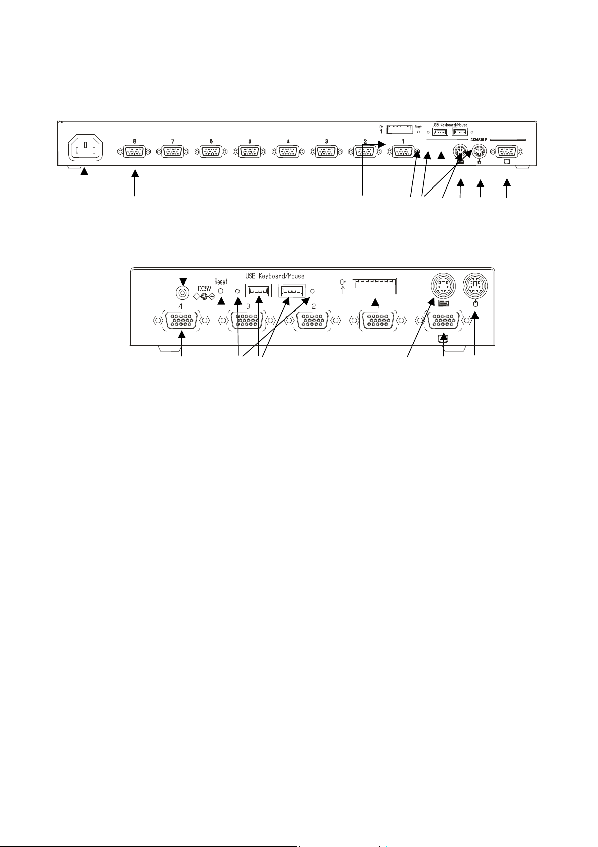
3.2 Rear Panel
6) 7) 13) 5) 9) 8) 10) 11) 12)
8 Port Rear Panel
14)
7) 5) 9) 8) 13) 10) 12) 11)
4 Port Rear Panel
6) Power cable connector
Connect to a 100 to 240V AC electric outlet.
7) Connectors for hosts [1 through 8]
Connect each port (1 through 8) on this device to the relevant host’s keyboard, mouse
and monitor connectors with the special cable.
8) USB keyboard / mouse Connector
Connect a USB keyboard / mouse here.
(Cannot be used concurrently with a PS/2 type keyboard and mouse. USB keyboard /
mouse have priority over PS/2 keyboard / mouse)
9) USB keyboard / mouse status LEDs
Green: This port can use or using.
Red : Over current was drawn from this port. Not in work.
Unplug the device and push a reset_sw.
unlit : Unsupported device or some error has occurred in this port.
Unplug the device or push a reset_sw.
10) PS/2 Keyboard connector
Connect a PS/2 keyboard here.
(Cannot be used concurrently with a USB type keyboard)
11) PS/2 Mouse connector
Connect a PS/2 mouse here.
(Cannot be used concurrently with a USB type mouse)
12) Monitor Connector
Connect a monitor here.
13) DIP Switches
Use for a variety of settings. Numbered from left side while facing the switches starting
from 1,2…8; up is on and down is off.
14) AC adapter connector
Connect the AC adapter here. Do not use any AC adapter other than the one provided
with the switch device.
9
Page 11

3.3 DIP Switch Settings
The factory default settings are as follows:
1 2 3 4 5 6 7 8
ON
OFF
(*Note: the indicates the switch position)
DIP Switch Functions
SW Function ON state / OFF state
1 Hot Key Mode: <Ctrl>+<Alt>+<Shift> ON: enabled / OFF: disabled
2 Hot Key Mode: Double <Ctrl> ON: enabled / OFF: disabled
3 Hot Key Mode: Double <Scroll Lock> ON: enabled / OFF: disabled
4 Country Setting bit 1 (see following table)
5 Country Setting bit 2 ( “ )
6 Country Setting bit 3 ( “ )
7 Country Setting bit 4 ( “ )
8 Power Mode Setting
The country code (language) settings are as follows:
Country Setting
Japan ON ON ON ON
US ON ON ON OFF
UK ON ON OFF ON
German ON ON OFF OFF
French ON OFF ON ON
Spanish ON OFF ON OFF
Swedish ON OFF OFF ON
SW4 SW5 SW6 SW7
The country code (language) settings are as follows:
Country Setting
JPN ON ON ON ON
USA
SW4 SW5 SW6 SW7
ON ON ON OFF
ON: the switch device is always ON.
OFF: the switch device turns ON if any connected
host is turned ON.
GBR ON ON OFF ON
GER ON ON
FRA ON OFF ON ON
ESP ON OFF ON OFF
SWE ON OFF OFF ON
POR ON OFF OFF OFF
TPE OFF ON ON ON
KOR OFF ON ON OFF
ITA OFF ON OFF ON
UNIX OFF ON OFF OFF
NOR OFF OFF ON ON
BEL OFF OFF ON OFF
DEN OFF OFF OFF ON
OFF
OFF
10
Page 12

11
Page 13

4. Installation Procedure (Rack Setup)
1. Remove the four flathead screws from the left and right sides of the switch device's console
panel.
2. Remove the console panel from the switch device, and attach the rack mount bracket (small) to
it. (Use the attached M3 screws. (4 pcs.))
3. Attach the rack mount bracket (large) to the rear panel side of the switch device. (use the
attached M3 screws. (6 pcs.))
4. Detach the console panel connector cable from the console panel before mounting it in the
rack. This makes it easy to mount the switch device.
5. Fix the console panel to the front side of the rack with screws.
6. Fix the rear panel to the rear of the rack with the screws.
7. Reattach the console cable (detached in step 4.) to the console panel.
Rear Panel Side
Console Panel Side
Mount bracket (large)
Mount bracket (small)
12
Page 14

aaaabaaaabbb b
d
c
c c
c
5. Setup
5.1. Getting started
Set the DIP switches to match your chosen environment.
Then confirm that the power cable for each host is plugged into an electric outlet and
that the power is off.
(Confirm connection (a))
5.2. Connecting the hosts (using single switch device)
1) Connect the first host’s keyboard, mouse connector and CRT connector with the special
cable (connect (b)), next connect the switch device’s host port connector (Mini D-Sub 15 pin
female) to the special connector (black). (connect (c)).
2) Connect hosts 2 through 8 in the same manner.
b
b b
c c c
c
c
c c
c
d
d
d
PS/2 Keyboard, Mouse
Monitor
aaaa
b
b b b
a a a a
b b
b b
c c c c
d
d
USB Keyboard, Mouse
Monitor
This switch device and the hosts should use a three-line type power cable,
CAUTION
with the ground line on the power cable grounded.
If you use a two-line plug adapter be sure to attach the ground wire to a
grounded object.
13
Page 15

3) After each host and switch device have been connected, connect the keyboard, mouse,
d
d
and monitor to the [CONSOLE] connectors on the switch device.
4) Attach switch device's AC power cable and then plug it into an electric outlet.
5) After confirming that the connections have been made correctly, start up the attached
hosts.
6) Acquire Plug-n-Play data for the monitor.
When a monitor is first attached to the switch device, its Plug-n-Play data (EDID data)
needs to be acquired by the switch device. Re-start the host to be able to use the
monitor with the acquired environment.
[Plug-n-Play data setting]
After connect the monitor to the switch device, push reset_sw or open the OSD via
the hot key press, then go to EDID setting mode (using NEXT PAGE), and press the
Enter key.
7) Select each port in turn and confirm the attached host is started up and using the
correct settings.
8) If the keyboard, mouse, or monitor is not set correctly, adjust the settings and restart
the system.
5.3. Connecting the hosts (using cascaded connections)
1) Connect the hosts one through eight to the second level of switch devices (called
slaves), in the same way as for the [first level].
2) Next, use the special cables to attach the host port connector of the first level switch
device (called master) to the [PS/2 keyboard], [PS/2 mouse], and [monitor] connectors
on the console ports of the second level slave switch devices.
3) To increase the number of slaves, connect them in the same way as described in steps
1 and 2 above. Do not connect slaves beyond the second level. Three level connection
does not work.
USB Keyboard, Mouse
Monitor
Second level
(Slave)
First level
(Master)
14
Page 16

4) After each host and switching device have been connected, connect the keyboard,
mouse, and monitor to the [CONSOLE] connectors on the (master) switch device.
5) Attach switch device's AC power cable and then plug it into an electric outlet.
6) After confirming that the connections have been made correctly, start up the attached
hosts.
7) Acquire Plug-n-Play data for the monitor.
When a monitor is first attached to the master switch device, its Plug-n-Play data
(EDID data) needs to be acquired by the switch device. Re-start the host to be able to
use the monitor with the acquired environment.
[Plug-n-Play data setting]
After connect the monitor to the switch device, push reset_sw or open the OSD via
the hot key press, then go to EDID setting mode (using NEXT PAGE), and press the
Enter key.
8) Select each port in turn and confirm the attached host is started up and using the
correct settings.
9) If the keyboard, mouse, or monitor are not set correctly, adjust the settings and restart
the system.
This switch device and the hosts should use a three-line type power cable,
CAUTION
with the ground line on the power cable grounded.
If you use a two-line plug adapter be sure to attach the ground wire to a
grounded object.
Only PS/2 cable is using to cascade connections.
Don’t connect USB devices to slave switch device. (Cascade connection will
be lost when slave switch device has USB devices)
15
Page 17

6. Operation (Host selection)
At the beginning, first powered up host is selected automatically. And if some hosts powered up at the same time,
a host which connected lower port No. is selected.
Also, when the power to a host is turned off while it is selected, the status is preserved. In that case, switch to the
host you want to select with the selector buttons or the Hot Keys.
In normal operation, there are two methods for selecting a host, the Host Selector Buttons and the OSD
display (Hot Key Mode).
6.1. Host selection by Host Selector Buttons (Normal mode)
Press the selector button of the host you want to select to switch the console to that host (the associated
SELECT LED lights up).
*Note: Do not press two selector buttons at the same time, doing so may cause an operation error.
Press the Auto Scan Button, the SELECT LEDs flash slowly, and after a set time (default value is 10 seconds)
the screen switches automatically. To change the switching interval, press the <?> cursor key to make it
incrementally faster and the <?> cursor key to make it incrementally slower. The available switching intervals
are 3/5/10 (default)/20/40/60 seconds. Hosts that are turned off are skipped. You cannot perform keyboard
operations or use the mouse during auto scan. Exit Auto Scan Mode if you want to move to the Hot Key Mode.
Exit auto scan with the following method.
Auto Scan Button, or Enter Key: Switches to the currently displayed screen.
ESC Key: Returns you to the host where Auto scan started.
6.2. Host Selection by Keyboard (Hot Key Mode)
The Hot Key Mode may be activated using any of the following three methods:
“Hot key mode A”:
Press Ctrl, Alt, Shift together. (Once)
Press Scroll Lock twice (Press the Scroll Lock key quickly in succession)
“Hot key mode B”:
Press Ctrl twice (Press the Ctrl key quickly in succession)
When the Hot Key Mode is activated, the OSD (On Screen Display) selection screen is shown on the monitor.
You can select hosts while looking at the OSD display.
The SELECT LED on the first level (master) switch device changes from being lit to flashing quickly regardless
of single use or cascade connection. The Select LEDs of any slave switch devices remain lit as normal and do
not blink.
And also, the Scroll lock LED on console keyboard starts blinking, and other LEDs are turned off.
*When there is no video (H/V Sync) signal from the currently connected host (suspended state), the OSD
menu can be displayed by the video (H/V Sync) signals from other ports. At this time, the OSD menu flashes at
5-second intervals.
When the video signal (H/V Sync) is input to the currently selected port, status returns to normal.
*H Sync: Horizontal sync signal
*V Sync: Vertical sync signal
16
Page 18

6.2.1. Hot Key Mode A
Press Ctrl, Alt, Shift once or press the Scroll Lock key twice to go into the Hot Key Mode and the following OSD
screen is displayed.
a) Screen Details
Example OSD Screen (probably different to actual screen)
1.) Center-left of screen (black background) shows the state of the (master) switch device ports.
2.) Center-right of screen (blue background) shows the state of any slave switch device cascade connected to
the current channel.
3.) Purple text shows the hosts currently selectable with the arrow (cursor) keys.
4.) The bottom of the screen shows simple explanations of allowed key operations.
5.) The mark shows the currently selected host (channel).
6.) Green numbers (1~8 or F1~F8) show the connected host is ON.
7.) Depending on whether the selected channel has a cascaded slave device attached to it or not, the OSD
master device display section (1. above) changes as follows:
? Non-cascaded channel: 14-character wide master device section / nothing in slave section.
(The OSD screen is the same without cascade connection.)
? Cascaded channel: 3-character wide master device section / 14-character wide slave section.
Example OSD Screen with cascaded channel selected
17
Page 19

8.) If a cascade-connected master channel or any slave channel is selected, while the <Shift> key is
pressed the OSD screen switches from “3-character master/14-character slave” mode back to
“14-character master/5-character slave” mode. The OSD reverts to normal 3/14 mode when the
<Shift> is released.
Cascade-connected master channel selected Slave channel selected
b) Host Switching
No normal keyboard or mouse input is accepted while the hot key mode.
[Switching Via Keyboard]
1). Use the <?> & <?> cursor keys to select a host (channel) on the left side of the OSD.
2). If a cascade-connected channel is selected, the state of the selected slave device is shown on the right side
of the OSD.
3). If a cascade-connected channel is selected, pressing the <? > cursor key causes control to switch to the right
(slave) side of the OSD, with the currently selected cascaded host shown in purple. Press the <? > cursor
key to return control to the left (master) side of the OSD.
4). On the right side of the OSD, use the <?> & <?> cursor keys as before to select a cascaded host (channel).
5). Press the <Enter> key to actually effect the console switch to the selected host. The name of the host
switched to is shown at the top-left of the screen for about 3 seconds after the switch is effected.
Press the <Esc> key to escape the Hot Key Mode without switching the console.
18
Page 20

[Switching Via Mouse]
The mouse may also be used to control the OSD (instead of the keyboard):
1). Scroll the mouse up & down to select a host (channel) on the left side of the OSD.
2). If a cascade-connected channel is selected, the state of the selected slave device is shown on the right side
of the OSD.
3). If a cascade-connected channel is selected, pressing the right mouse key causes control to switch to the right
(slave) side of the OSD, with the currently selected cascaded host shown in purple. Press the left mouse key
to return control to the left (master) side of the OSD.
4). On the right side of the OSD, scroll the mouse up & down as before to select a cascaded host (channel).
5) Press the center mouse key to actually effect the console switch to the selected host. The name of the host
switched to is shown at the top-left of the screen for about 3 seconds after the switch is effected.
[Direct Switching Via Keyboard]
4/8-port KVM switch (for the 4-port device, read “8” as “4”):
Use the number keys <1>~<8>.
For a cascaded setup, first use the number keys <1>~<8> to select a master-side channel, then use the function
keys <F1>~<F8> to select a slave-side port.
Switching occurs immediately after the appropriate keys are pressed, and the OSD reverts to the normal
console (Hot Key Mode is finished).
When selecting a port in a cascaded connection, select the port on the master side firstly.
Then, select and switch to the port on the slave side.
[Direct Switching Via Host Selector Buttons]
Press the Selector Button “1”~” 8” on the switch device’s console panel to select a host.
To select a cascaded host, press the Selector Button “1”~”8” on the slave KVM device’s console panel.
Switching occurs immediately after the selector button is pressed, and the OSD reverts to the normal console
(Hot Key Mode is finished).
[Auto Scan Mode]
Pressing the keyboard’s <0> key, starts the console screen switching each time the “Auto Scan Interval” elapses,
with the Select LEDs to switch to a slow blink.
The switching interval (Auto Scan Interval) may be adjusted by pressing the <?> cursor key to make it faster
(shorter) and the <?> cursor key to make it slower (longer).
Allowed Auto Scan Intervals are: 3, 5, 10 (default), 20, 40 and 60 seconds
The new Auto Scan Interval is shown on the OSD for 3 seconds.
Hosts that are powered OFF are skipped. No normal keyboard or mouse input is accepted while the Auto Scan
Mode is running.
To return to Hot Key Mode, the Auto Scan Mode must first be cancelled.
Auto Scan Mode may be cancelled as follows:
<Enter> key: Console switches to the currently displayed screen (host).
<Esc> key: Console reverts to the host active before Auto Scan Mode was entered.
19
Page 21

C) Setting/Changing Host Names
1). Select the host name to be set/changed using the cursor keys, exactly as if switching.
2). Press the <Tab> key.
3). The selected name turns yellow, with a single black on yellow character.
4). Use the keyboard to enter the desired name, then press the <Enter> key to confirm it.
Use the <Del> key to delete a single character, and the <BS> key to backspace.
Use the <Esc> key to cancel an unconfirmed name (revert to original name).
5). A host name may be up to 14-characters long.
6). Any of the following 47 characters may be used:
ABCDEFGHIJKLMNOPQRSTUVWXYZ1234567890,./[]:+*-+ and <Space>
Changing a master-side name Changing a slave-side name
(Single KVM setup has no blue area)
7). Pressing the Reset Switch with the <1> and <3> front switches also held down causes any set names to be
discarded and reverts the device to the factory defaults. This will occur even if the device is in normal
Console Mode (not Hot Key Mode).
Note that if the device is reset in this way, any names that were set are lost, and not recoverable.
20
Page 22

6.2.2. Hot Key Mode B
Press the <Ctrl> key twice to go into the Hot Key Mode and the following OSD screen appear in the upper-left of
the screen.
a) Screen Details
1). Selected host name is shown in the OSD in the upper left of the screen.
2). Before switching the text background turns in red.
3). After switching the text background turns in blue, and the Hot Key Mode is exited after the switch is
completed.
4). The OSD disappears about 3 seconds later.
b) Host Switching
When the text background turns in red, the desired host may be switched to by pressing the matching number
key(s):
4/8-port KVM switch (for the 4-port device, read “8” as “4”):
Use the number keys <1>~<8>.
For a cascaded setup, first use the number keys <1>~<8> to select a master-side channel, then use the function
keys <F1>~<F8> to select a slave-side port.
Switching occurs immediately after the appropriate keys are pressed, and the OSD reverts to the normal console
(Hot Key Mode is finished).
No normal keyboard or mouse input is accepted while the text background is in red.
To change the text background back to blue (exit Hot Key Mode), either press a number key (combination), or
press the <Esc> key, or the <Enter> key.
If the <0> key is pressed while the text background is red, Auto Scan Mode is entered.
Auto Scan Mode may be cancelled as follows:
<Enter> key: Console switches to the currently displayed screen (host).
<Esc> key: Console reverts to the host active before Auto Scan Mode was entered.
6.3. Showing/Hiding Host Names Function
[Showing/Hiding Host Name Function]
When the device is operating in normal Console Mode, holding the <Shift> key down and pressing the <Scroll
Lock> key twice make the host name for the currently selected channel to be shown in the top-left of the screen.
(Showing Host Names)
If the host name is being displayed, holding the <Shift> key down and pressing the <Scroll Lock> key twice again
changes the host name to disappear from the screen. (Hiding Host Names)
The factory default is hiding the host names.
The showing host name is not appeared when Hot Key Mode, Auto scan mode is active.
While in the Hot Key Mode, holding the <Shift> key down and pressing the <Scroll Lock> key twice will not change
the host name to be shown/hidden.
The current Show/Hide Host Name state is retained after switching the host via selector buttons or OSD.
21
Page 23

6.4. EDID Setting Mode
After pressing the <Ctrl>+<Alt>+<Shift> keys or double pressing the <Scroll Lock> to activate the Hot Key
Mode A, pressing the <N> key changes the display to switch to the Customer Mode:
The top line accesses the EDID Setting Mode.
The bottom line displays the firmware version currently installed.
Pressing the <Enter> key on this screen causes the text background to turn purple, while the EDID information
is retrieved from the monitor connected to the console port and written to the internal ROM.
After the ROM has been written, the message “PNP MONITOR” is displayed.
When EDID information cannot be retrieved from the connected monitor, the message “DEFAULT MONITOR”
is displayed, and “00” is written to the ROM.
If a new monitor is connected, and the EDID Setting performed, the internal ROM setting is subsequently
transmitted to each host automatically.
The EDID Setting Mode may be ended as follows:
Press the <P> key to return to the Host Selection screen (Hot key mode A).
Press the <Esc> key to escape the Hot Key Mode and return to the normal console screen.
22
Page 24

We recommend a noninterlaced video signal for the on screen display.
CAUTION
(However, it is possible to display an interlaced signal with a resolution of 1152 x 864, 1280 x
1024, or 1600 x 1200. However at resolutions lower than this and the display may extend beyond
the edges of the screen.
When push the Reset Switch, EDID setting is also done automatically.
23
Page 25

7. Specifications
Item Specification
Product ID
(Model)
Number of Connected
Host Devices
Selection Method Host Selector Buttons, OSD Display (Hot Key Mode)
POWER (Green) 4 8 LED Display
SELECT (Green) 4 8
Host Interfaces
PS/2 Keyboard PS/2 Keyboard Interface compliant
PS/2 Mouse PS/2 Mouse Interface compliant
USB
Keyboard & Mouse
Sun Serial
Keyboard & Mouse
Host Ports Mini D-SUB 15P
Console
Ports
PS/2 Keyboard PS/2, Mini DIN 6P Female x 1 (Purple)
PS/2 Mouse PS/2, Mini DIN 6P Female x 1 (Green)
USB
Keyboard & Mouse
Monitor Mini D-SUB 15P Female x 1 (Blue)
OSD Modes Manual (Hot Key) Mode / Auto Scan Mode
Auto Scan Intervals 3 / 5 / 10 (default ) / 20 / 40 / 60 seconds
Monitor Resolution
Refresh Rate
Monitor Plug & Play Function VESA DDC2 Compatible
Voltage DC5V AC100V to AC240V 50/60Hz
Current 0.6A (DC) 0.2A (AC100V)
Supply Current to Keyboard/Mouse PS/2 port 300mA (typ.) , USB port 250mA (typ.)
Operating Environment 0~40ºC / 10~80%RH (avoid condensation)
Storage Environment -20~60ºC (avoid condensation)
Construction Painted (Black) Metal Case
Size (W x D x H) 195 x 104 x 40 mm 437 x 210 x 42 mm
Weight
Included Accessories User’s Manual (x 1)
FS-1004MU
(KVM switch)
Max. 4 (more if connections are
cascaded)
FS-1008MU
(KVM Switch)
Max. 8 (more if connections are
cascaded)
USB 1.1 compliant
USB HID device, keyboard & mouse composite device
SUN Keyboard/Mouse compliant
Mini D-SUB 15P
Female x 4 (Black)
Female x 8 (Black)
USB type A X 2
1600 x 1200 (Max.)
75Hz
0.1A (AC240V)
0.8kg
3.0kg
User’s Manual (x 1)
AC Adapter (x 1)
19-inch Rackmount Holder
(Large x1+Small x 1 + Fastening
Screws)
24
Page 26

8. Optional Accessories (Sold separately)
l KVM Special Cables
Item Product ID Remark
Combined Keyboard + Mouse +
Monitor Cable (1.8m)
Combined Keyboard + Mouse +
Monitor Cable (3.0m)
Combined Keyboard + Mouse +
Monitor Cable (5.0m)
l AC Cables
Item Product ID Remark
For USA NC14004-B074
For EUROPE NC14004-B075
NC14000-B602
NC14000-B102
NC14000-B202
NC14000-B603
NC14000-B103
NC14000-B203
NC14000-B605
NC14000-B105
NC14000-B205
NC14004-B077
NC14004-B078
PS/2 cable (this cable may be used for
cascade connections)
USB cable
Sun cable
PS/2 cable
USB cable
Sun cable
PS/2 cable
USB cable
Sun cable
8Port KVM
4Port KVM (AC Adapter)
8Port KVM
4Port KVM (AC Adapter)
For UK NC14004-B076
NC14004-B079
8Port KVM
4Port KVM (AC Adapter)
l Misc.
Item Product ID Remark
Rackmount Panel NC14003-T038 For 4 port KVM
Sun CRT cable adapter NC14003-T042/ADP 13 W 3(M) <-> DB 15 HD
25
Page 27

9. Troubleshooting
Symptom Cause Action
The POWER LED is flashing.
The AC cord is not connected to the electric
outlet or to the switch device.
The AC power is off. Turn on the AC power.
The internal power fuse has blown. Contact the place of purchase or the
Connect the AC cord.
support center.
The keyboard and mouse do
not operate or operate
strangely.
(Special programmable,
cordless or mice with wheels)
does not operate.
Poor screen quality
(Faded images, blurred
characters, etc.)
Window shifts or does not
display when switching
Cannot go into Auto Scan Mode
The keyboard and mouse connections on the
host are reversed.
Cannot get out of Hot Key Mode Press the [Enter] or [ESC] key
The key repeat is abnormal. Change the speed setting for the key
Connection/cable is defective Confirm the connector connection.
A non-supported keyboard or mouse is
connected.
Mouse not supported Replace with a supported mouse. The scroll function or button
The specific mouse driver is not installed. Install the specific mouse driver.
Connection/cable is defective Confirm the connector connection.
Wrong resolution Adjust the resolution or use the
Unsupported monitor, or cannot
synchronize
Device enters Hot Key Mode The device goes into Hot Key Mode,
Match the port Nos.
repeat on the host.
Replace with a different cable. If this
solves the problem, replace with a new
cable.
Replace with a supported keyboard
or mouse.
Replace with a different cable. If this
solves the problem, replace with a new
cable.
monitor function.
Replace with a supported monitor
(multisync).
Use the monitor function.
press the number key (0).
Wrong key Press the number key (0).
Cannot go into Hot Key Mode Wrong key First level are the number keys (1 through
8).
Second level are F1 through F8.
The auto scan switch cycle is
abnormal.
Operation stops after a period of
normal operation.
The LED on the device does
not light even after turning on
the host.
Cascaded connections are not
recognized.
The switch cycle has not been adjusted.
(The default value is 10 seconds.)
Connection has been disrupted. Check the connections and the restart.
The switcher is hung up. Press the reset switch.
A problem has occurred at the host. Correct the problem at the host.
The host’s keyboard/mouse port’s power circuit
protection element has failed.
A problem has occurred at the switcher. Press the reset switch.
26
Use the cursor keys (? and ?) to adjust it.
Correct the problem at the host.
(Both the slave and the master)
Page 28

n Key layout diagram 1
‑
*.9
F10
F11
F12
Print
End
Num
Lock/7
Home86324150
Enter
‑
*.9
F10
F11
F12
Print
End
Num
Lock/7
Home86324150
Enter
Power
(ASCII keyboard for PC/AT compatible machines)
(1) When connecting to a PC/AT compatible machine
Esc F1 F2 F3 F4 F5 F6 F7 F8 F9
Screen
Scroll
Lock
Pause
BreakSysRq
*
Tab
CapsLock
Shift
Ctrl
^
Alt Alt
(2) When connecting to a Sun workstation
Esc F1 F2 F3 F4 F5 F6 F7 F8 F9
^
Tab
CapsLock
*
Shift
Ctrl
Screen
Scroll
Lock
Home
Home
Pause
BreakSysRq
Page
Up
Page
Down
Page
Up
Page
Down
Vol+Vol‑Mute
Shift
Ctrl
Shift
Alt
Compose
Fn
Ctrl
27
Page 29

n Key layout diagram 2
+‑‑
+
.
0
Ins
Del123564789/
Num
Lock
Graph
Shift
+‑‑
+
CapsLock
Del123564789/
Num
Lock
‑
+
(ASCII keyboard for Sun)
(1) When connecting to a Sun workstation
Help
Help
Esc
Tab
Ctrl
Shift
CapsLock
Alt
(2) When connecting to a PC/AT compatible machine
Esc
Tab
Com‑
pose
F12F11F10F9F8F7F6F5F4F3F2F1
Alt‑
F12F11F10F9F8F7F6F5F4F3F2F1
Print
Screen
SysRq
Print
Screen
SysRq
Scroll
Lock
Scroll
Lock
Pause
Break
Pause
Break
Ctrl
Shift
Alt
Shift
Ctrl
0
Ins
.
28
Page 30

n Appendix: Host name record sheets
Record a list of the names of the hosts that attached to your switch device.
NO. NAME
Master Unit
NO. NAME
1
2
3
4
5
6
7
8
Slave Unit Port.1
1
2
3
4
5
6
7
8
Slave Unit Port.6
NO. NAME
1
2
3
4
5
6
7
8
Slave Unit Port.2
NO. NAME
1
2
3
4
5
6
7
8
Slave Unit Port.3
NO. NAME
1
2
3
4
5
6
7
8
Slave Unit Port.7
NO. NAME
1
2
3
4
5
6
7
8
Slave Unit Port.4
NO. NAME
1
2
3
4
5
6
7
8
Slave Unit Port.5
NO. NAME
1
2
3
4
5
6
7
8
Slave Unit Port.8
NO. NAME
1
2
3
4
5
6
7
8
29
Page 31

Declaration of Conformity
Model Number : FS-1004MU, FS-1008MU
Trade Name : KVM Switch
Responsible party : FUJITSU COMPONENT AMERICA, INC.
Address : 250 East Caribbean Drive, Sunnyvale,CA94089
Telephone number : (408) 745-4900
This device complies with Part 15 of the FCC Rules. Operation Is subject to the following two
conditions : (1) this device may not cause harmful Interference, and (2) this device must accept any
Interference received, Including Interference that may cause undesired operation. DOC Class B
KVM Switch [FS-1004MU / FS-1008MU Series]
User’s Manual
Published March 2005
Published by FUJITSU COMPONENT LIMITED
Printed in Japan
All trademarks or registered trademarks are the property of their respective owners. The information contained in this
document has been carefully checked and is believed to be reliable. However, FUJITSU COMPONENT
LIMITED (FCL) or its affiliates assume no responsibility for inaccuracies. The information contained in this document
does not convey any license under the copyrights, patent rights or trademarks claimed and owned by FCL or its
affiliates. FCL or its affiliates bear no responsibility for infringement of patent or other rights of third parties
attributed to the use of information in this manual. FCL or its affiliates reserve the right to change products or
specifications without notice. No part of this publication may be copied or reproduced in any form or by any means, or
transferred to any third party without the prior written consent of FCL
30
Page 32

This manual is made of recycled paper.
31
 Loading...