

Fujitsu FPCM11641 - INTEL CORE 2 DUO PROCESSOR P8600 CENTRINO, LIFEBOOK T5010 Operating Manual
Page 1

LIFEBOOK T5010
Operating Manual Notebook
Page 2

Are there ...
... any technical problems or other questions which you would like help with?
Please contact:
● our Hotline/Service Desk (see the enclosed Service Desk List or refer to our website:
http://ts.fujitsu.com/servicedesk)
● your sales partner
● Your sales office
Additional information is contained in the Service Desk list and the "Warranty" manual. You will find
the "Warranty" manual on the "Drivers & Utilities" CD/DVD supplied and on the Internet at
http://ts.fujitsu.com/support
The latest information on our products, tips, updates, etc., can be found on our website at:
http://ts.fujitsu.com
Page 3

Page 4

Copyright
© Fujitsu Technology Solutions 2009
2009/08
Published by
Fujitsu Technology Solutions GmbH
Mies-van-der-Rohe-Straße 8
80807 München, Germany
Contact
http://ts.fujitsu.com/support
All rights reserved, including intellectual property rights. Technical data subject to modi cations and delivery subject to availability. Any
liability that the data and illustrations are complete, actual or correct is excluded. Designations may be trademarks and/or copyrights of
the respective manufacturer, the use of which by third parties for their own purposes may infringe the rights of such owner. For further
information see http://ts.fujitsu.com/terms_of_use.html
Order-No. Fujitsu Technology Solutions: A26391-K276-Z226-1-7619
Page 5

Introduction
LIFEBOOK T Series
Troubleshooting
and tips
Important notes
Technical data
Equipment overview
Manufacturer’s notes
Preparing the notebook
for use
Index
Using your notebook
Operating Manual
Security functions
Connecting
external devices
Removing/installing
components (during
servicing)
Energy saving functions
Settings in the
BIOS Setup
Edition 2, August 2009
Page 6

Adobe and Acrobat are trademarks of Adobe Systems Incorporated and may be protected in
certain countries.
The Bluetooth trademarks are the property of Bluetooth SIG, Inc., U.S.A. and licensed to
Fujitsu Technology Solutions GmbH.
Intel is a registered trademark and Core is a trademark of Intel Corporation, USA.
Kensington and MicroSaver are registered trademarks of ACCO World Corporation.
Microsoft, MS, Windows, Windows XP, Windows Vista, Windows 7 are registered trademarks
of the Microsoft Corporation.
All other trademarks referenced are trademarks or registered trademarks of their respective
owners, whose protected rights are acknowledged.
Copyright © Fujitsu Technology Solutions GmbH 2009
All rights, including rights of translation, reproduction by printing, copying or similar methods,
in part or in whole, are reserved.
Offenders will be liable for damages.
All rights reserved, particularly for rights created by patent grant or registration of a utility
model or design.
Delivery subject to availability. Right of technical modification reserved.
Page 7

Contents
Your LIFEBOOK T............................................................................................................................... 1
Notational conventions ......................................................................................................................... 2
Important notes .................................................................................................................................. 3
Safety notes.......................................................................................................................................... 3
Additional safety notes for devices with radio components.......................................................... 3
Notes on installing and removing boards and components.......................................................... 4
Travelling with your notebook............................................................................................................... 5
Before you travel .......................................................................................................................... 5
Transporting your notebook.......................................................................................................... 6
Cleaning ............................................................................................................................................... 6
An overview of your notebook .......................................................................................................... 7
Notebook open ..................................................................................................................................... 7
Left side................................................................................................................................................ 8
Rear 9
Right side.............................................................................................................................................. 9
Underside ........................................................................................................................................... 10
Ports on the port replicator (accessory for LIFEBOOK T5010) .......................................................... 11
Preparing the notebook for use ...................................................................................................... 13
Unpacking and checking the delivery................................................................................................. 13
Selecting a location ............................................................................................................................ 14
Connecting the mains adapter............................................................................................................ 15
Switching the notebook on for the first time........................................................................................ 17
Using your notebook........................................................................................................................ 19
Opening and closing the notebook..................................................................................................... 19
Opening the notebook ................................................................................................................ 19
Closing the notebook.................................................................................................................. 20
Different ways to use your notebook .................................................................................................. 20
From notebook to Tablet PC ...................................................................................................... 21
Select display orientation (portrait or landscape orientation) ..................................................... 23
From Tablet PC to notebook ...................................................................................................... 24
Switching the notebook on and off ..................................................................................................... 27
Switching on the notebook ......................................................................................................... 27
Switching the notebook off ......................................................................................................... 28
Status indicators................................................................................................................................. 29
Language selection (Windows XP only)............................................................................................. 31
Specifying the language variant for multi-language models....................................................... 31
LCD screen......................................................................................................................................... 33
Notes about the LCD screen ...................................................................................................... 33
Screen settings (when using the device as a notebook) ............................................................ 34
Screen settings (when using the device as a Tablet PC)........................................................... 35
Using a notebook as a tablet PC........................................................................................................ 35
Using your finger (only with Dual Digitizer technology) .............................................................. 35
Using the pen ............................................................................................................................. 37
Using a notebook................................................................................................................................ 41
Touchpad and touchpad buttons................................................................................................ 41
Keyboard ............................................................................................................................................ 43
Virtual numeric keypad............................................................................................................... 45
Key combination......................................................................................................................... 45
Tablet buttons............................................................................................................................. 47
A26391-K276-Z226-1-7619, edition 2
Page 8

Contents
Battery.................................................................................................................................................49
Charging, caring for and maintaining the battery ........................................................................49
Removing and installing the battery............................................................................................51
Modules...............................................................................................................................................52
Removing a module ....................................................................................................................53
Installing a module......................................................................................................................54
Optical drive ........................................................................................................................................54
Inserting or removing a CD/DVD ................................................................................................55
ExpressCards......................................................................................................................................56
ExpressCard inserting.................................................................................................................57
Ejecting a PC card ......................................................................................................................58
Memory cards .....................................................................................................................................59
Inserting a memory card .............................................................................................................59
Removing a memory card...........................................................................................................59
Data transfer .......................................................................................................................................59
UMTS and SIM card (optional) ...................................................................................................59
Wireless LAN/Bluetooth/UMTS radio components (optional) .....................................................61
Port Replicator ....................................................................................................................................64
Setting up the Port Replicator.....................................................................................................64
Connecting the notebook to the Port Replicator .........................................................................65
Switching on the notebook via the Port Replicator .....................................................................66
Switching off the notebook via the Port Replicator .....................................................................66
Disconnecting the notebook from the port replicator ..................................................................67
Security functions.............................................................................................................................68
Brief overview of security functions.....................................................................................................69
Using the Kensington Lock .................................................................................................................70
Configuring the fingerprint sensor.......................................................................................................71
Configuring password protection in the BIOS Setup...........................................................................72
Password protection for BIOS Setup (supervisor and user password).......................................72
Password protection for starting the operating system...............................................................73
Password protection for hard disk...............................................................................................74
Using the SmartCard reader ...............................................................................................................75
SmartCards.................................................................................................................................75
SmartCard SystemLock (optional) ......................................................................................................77
Access rights of SmartCards ......................................................................................................78
SmartCard user groups...............................................................................................................79
Installing SystemLock .................................................................................................................80
Setting up the first system in a user group or a stand-alone system for use with
SystemLock ........................................................................................................................
80
Adding a system to a user group ................................................................................................83
Carrying out administrator functions ...........................................................................................84
Remote unlock – F4....................................................................................................................86
Switching on the device with SystemLock ..................................................................................87
Start BIOS Setup – F2 ................................................................................................................87
Change PIN ................................................................................................................................87
Uninstall SystemLock..................................................................................................................88
Error messages...........................................................................................................................88
Trusted Platform Module.....................................................................................................................88
Connecting external devices............................................................................................................91
Connecting an external monitor to the notebook ................................................................................91
Connecting an external monitor to the Port Replicator .......................................................................92
Connecting USB devices ....................................................................................................................92
Connecting external audio devices .....................................................................................................93
A26391-K276-Z226-1-7619, edition 2
Page 9

Contents
Memory expansion ........................................................................................................................... 95
Installing and removing the memory extension .................................................................................. 95
Testing memory modules after the installation........................................................................... 98
Energy saving function.................................................................................................................... 99
Settings in the BIOS Setup ............................................................................................................ 101
Starting the BIOS Setup ................................................................................................................... 101
Operating BIOS Setup...................................................................................................................... 101
Exiting BIOS Setup........................................................................................................................... 102
Troubleshooting and tips............................................................................................................... 103
Help if problems occur...................................................................................................................... 103
Troubleshooting................................................................................................................................ 104
The notebook's date or time is incorrect................................................................................... 104
Battery indicator does not illuminate ........................................................................................ 104
The LCD screen of the notebook remains blank ...................................................................... 105
The LCD screen is difficult to read ........................................................................................... 105
The external monitor remains blank ......................................................................................... 106
The external monitor is blank or the image is unstable ............................................................ 107
The cursor does not correctly follow the pen movements ........................................................ 107
Pen input not working............................................................................................................... 107
The notebook cannot be started............................................................................................... 108
The notebook does not react.................................................................................................... 109
The mouse does not work ........................................................................................................ 109
The printer does not print ......................................................................................................... 110
The notebook shuts down suddenly......................................................................................... 110
A component (e.g. optical drive) is not detected or is not ready .............................................. 110
The wireless components are not available ............................................................................. 110
The ON/OFF switch does not respond as intended ................................................................. 111
The radio connection to a network does not work.................................................................... 111
The battery discharges too quickly........................................................................................... 112
The CD/DVD does not work – no sound during CD/DVD playback ......................................... 113
User and/or supervisor password forgotten.............................................................................. 113
SmartCard reader is not recognised ........................................................................................ 114
SmartCard PIN forgotten.......................................................................................................... 114
SmartCard lost ......................................................................................................................... 114
User and/or supervisor SmartCard lost .................................................................................... 114
Acoustic error messages.......................................................................................................... 115
Error messages on the screen ................................................................................................. 115
Restore operating system (Recovery CD/DVD can be ordered separately) ............................ 117
Technical data................................................................................................................................. 119
Notebook .......................................................................................................................................... 119
Port Replicator (optional).................................................................................................................. 121
Battery .............................................................................................................................................. 122
Mains adapter................................................................................................................................... 122
Manufacturer’s notes ..................................................................................................................... 123
Energy Star....................................................................................................................................... 123
Recycling and disposal..................................................................................................................... 123
CE marking....................................................................................................................................... 123
Tested safety (GS) ........................................................................................................................... 123
Regulatory notices............................................................................................................................ 124
Regulatory information for notebooks without radio device...................................................... 124
FCC Regulatory information for notebooks with radio device .................................................. 128
A26391-K276-Z226-1-7619, edition 2 3
Page 10

Contents
Index.................................................................................................................................................131
A26391-K276-Z226-1-7619, edition 2
Page 11

Your LIFEBOOK T...
... is a convertible notebook which works just as well and reliably as a notebook as it does as a tablet
PC. You can put the convertible notebook on the table as a notebook or hold it in your hands as a
tablet PC. Use the keyboard to type or write directly on the display with the pen. The convertible
notebook is always there to support you when you are working on the move.
Your operating system is pre-installed on the hard disk to facilitate the procedure when you use your
notebook for the first time. In addition to the well-known Windows functionality, this operating system
also has handwriting recognition as well as other settings that are specific for its use as a Tablet PC.
Depending on the model, your notebook may be equipped with the new technology "Turbo Memory"
from Intel®. The additional memory guarantees that your notebook will provide faster loading times
(system start-up) and lower power consumption. This memory can be configured using the User
Interface from Intel®.
If you connect the notebook to a port replicator (which is available to order as an optional accessory)
you can enjoy the benefits of a number of additional connection options. The port replicator provides
you with LAN and monitor ports (analogue and digital) and HDMI connection, as well as four USB 2.0
interfaces. Here you can connect peripheral devices such as a scanner, loudspeakers, gamepads,
keyboard, or mouse.
Your notebook has a number of security functions to ensure that no unauthorised persons can
access your data. For example, you can protect access to your data with the security functions in the
BIOS Setup or with the fingerprint sensor.
This operating manual shows you how to start using your notebook and how to operate it in daily
use.
Further information on this device is provided:
● in the "Safety" manual
● in the documentation of the operating system
● in the information files (e.g. *.TXT, *.DOC, *.WRI, *.HLP, *.PDF, *.HTML)
Some of the manuals listed can be found on the "Drivers & Utilities" CD/DVD and on the
i
Internet at:
using the Acrobat Reader program, which is also on the CD/DVD. If necessary, you can
also make a print version of the manual.
http://ts.fujitsu.com/support. You can access and view the required information
A26391-K276-Z226-1-7619, edition 2 1
Page 12

Your LIFEBOOK T...
Notational conventions
The following notational conventions are used in this manual:
Indicates information which is important for your health, the operability of your
!
notebook or the safety of your data. Faults on the notebook caused by your
failure to follow the instructions will invalidate your warranty.
Indicates important information which is required to use the system properly.
i
► Texts which follow this symbol describe activities that must be performed.
This font indicates screen outputs.
This font indicates programme names, commands, or menu items.
"Quotation marks" indicate names of chapters, data carriers, and terms that are being
emphasised.
2 A26391-K276-Z226-1-7619, edition 2
Page 13

Important notes
Here you will find essential safety information regarding your notebook. The other notes provide
helpful information on your notebook.
Safety notes
Pay attention to the information provided in the "Safety" manual and in the following safety
!
● When connecting and disconnecting cables, observe the relevant notes in this operating
notes.
Observe the sections in the manual marked with the symbol on the left.
manual.
● When cleaning the device, please observe the relevant notes in the section "
● If you have a device with radio components, please also note the information in the “Additional
safety notes for devices with radio components” section of the “Safety” manual.
● Do not drop the device. Make sure that the display does not come into contact with hard
objects which could destroy it. Otherwise the display could shatter into splinters which could
cause injury.
This notebook complies with the relevant safety regulations for data processing equipment. If you
have questions about using your notebook in a particular area, please contact your sales outlet or
our Hotline/Service Desk.
Cleaning".
Additional safety notes for devices with radio components
● Switch off the radio components (the ON/OFF switch for the radio components must be in the
"OFF" position) when you are at an airport or driving in a car.
● Switch off the radio components (the ON/OFF switch for radio components must be in the
"OFF" position) when you are in a hospital, an operating theatre or near electronic medical
equipment. The transmitted radio waves can impair the operation of medical devices.
● Switch off the radio components (the ON/OFF switch must be in the "OFF" position), when you
take the device close to flammable gases or into hazardous environments (e.g. petrol station,
paintshops), as the transmitted radio waves can cause an explosion or a fire.
● Always hold the device so that the antenna, which is built into the display frame and unfolded,
does not touch the body.
A26391-K276-Z226-1-7619, edition 2 3
Page 14

Important notes
Notes on installing and removing boards and components
Only qualified technicians should repair the device. Unqualified users who open the
!
Boards with electrostatic sensitive devices (ESD) are identifiable by the label shown.
When you handle boards fitted with ESDs, you must, under all circumstances, observe the following
points:
notebook’s case expose themselves to electric shock and fire hazards.
● You must statically discharge yourself before working with boards (e.g. by touching a grounded
object).
● The equipment and tools you use must be free of static charges.
● Pull out the power connector and remove the battery before you install or remove boards.
● Always hold boards with ESDs by their edges.
● Never touch pins or conductors on boards fitted with ESDs.
4 A26391-K276-Z226-1-7619, edition 2
Page 15

Important notes
Travelling with your notebook
Please observe the points listed below when travelling with your notebook.
Before you travel
● Back up important data stored on your hard disk.
● Switch off the radio component (Wireless LAN/Bluetooth) for data security reasons. With data
traffic via a wireless connection, it is also possible for unauthorised third parties to receive data.
Information on activating data encryption is provided in the documentation for your
i
● If you wish to use your notebook during a flight, first check with the flight attendants if it is OK to
do so.
When travelling in other countries
radio component.
● If you are travelling abroad, check that the mains adapter can be operated with the local mains
voltage. If this is not the case, obtain the appropriate mains adapter for your notebook.
Do not use any other voltage converter!
● Do not use a connection adapter for electrical devices to connect the notebook.
● Enquire with the corresponding government office of the country you will be travelling in as to
whether you may operate the radio component integrated in your notebook there (also see "
marking").
CE
A26391-K276-Z226-1-7619, edition 2 5
Page 16

Important notes
Transporting your notebook
● Remove all data carriers (e.g. CD) from the drives.
● Use the on/off switch to turn the notebook off (see Notebook: Switching off) and make sure
that it is completely switched off.
● Unplug the mains adapter and all external devices from the power socket.
● Disconnect the mains adapter cable and the data cables for all external devices.
● Close the connector covers.
● Close the LCD screen so that it locks into place.
● If the device needs to be shipped, use the original packaging or other suitable packaging to
protect it from damage caused by mishandling.
● To protect the notebook against damaging jolts and bumps, use a notebook carrying case to
transport your notebook.
● Current offers can be found on the Internet under http://ts.fujitsu.com/accessories.
● Protect the notebook from severe shocks and extreme temperatures (e.g. direct sunlight in a
car).
Cleaning
► Switch the notebook off.
► Pull the power plug of the network adapter out of the mains outlet.
► Remove the battery.
Do not clean any interior parts yourself; leave this job to a service technician.
!
Cleaning the surface of the casing and the fingerprint sensor
Wipe the casing with a dry cloth.
If particularly dirty, use a cloth that has been moistened in mild domestic detergent and then carefully
wrung out.
Cleaning the touchpad
To clean the touchpad, you can use disinfectant wipes.
Cleaning the screen
To clean the screen, gently wipe its surface with a soft Microfiber
Do not use any cleaning agents that contain abrasives or may corrode plastic. The use of
improper cleaning agents can damage the markings on the keyboard and the notebook,
the paintwork of the device or the device itself.
Ensure that no liquid enters the notebook.
®
cloth.
6 A26391-K276-Z226-1-7619, edition 2
Page 17

An overview of your notebook
Notebook open
2
1
12
11
6
10
9
1 = LCD screen
2 = Webcam
3 = Tablet buttons
4 = ON/OFF switch
5 = Status indicators
6 = Loudspeakers
3
4
5
6
7
5
8
7 = Keyboard
8 = ON/OFF switch for radio components
9 = Touchpad
10 = Touchpad buttons
11 = Fingerprint sensor
12 = Scroll sensor
A26391-K276-Z226-1-7619, edition 2 7
Page 18

An overview of your notebook
Left side
1
1 = DC input connector (DC IN)
2 = Attachment eye for the pen cord
3 = Microphone port
4 = Headphone port
5 = USB port
6
2
34
5
6 = FireWire connection (IEEE1394)
7 = ExpressCard slot
8 = Memory card slot
9 = SmartCard reader
10 = Pen slot
78
2
9
10
8 A26391-K276-Z226-1-7619, edition 2
Page 19

An overview of your notebook
Rear
1
2
3
4
5
6
1 = Kensington Lock
2 = SIM card slot
3 = USB port
The SIM card slot, LAN port and VGA monitor port are protected with covers.
4 = VGA monitor port (analogue)
5 = LAN port
6 = USB port
Right side
1 = Kensington Lock 2 = Module bay for drive or second battery
A26391-K276-Z226-1-7619, edition 2 9
1
2
Page 20

An overview of your notebook
Underside
5
1 = Air filter
2 = Memory service compartment
3 = Connection for port replicator
21
3
4 = Eject lever for module in module bay
5 = Battery compartment
4
10 A26391-K276-Z226-1-7619, edition 2
Page 21

An overview of your notebook
Ports on the port replicator (accessory for
LIFEBOOK T5010)
1
1
2
3
4
5
6
8
7
1 = USB ports
2 = DVI-D monitor port (digital)
3 = HDMI port
4 = VGA monitor port (analogue)
5 = LAN port
6 = Headphone port
Some of the devices that you connect require special drivers (see the operating system
i
and device documentation).
9
11
10
7 = Kensington Lock
8 = DC input connector (DC IN)
9 = Connection for LIFEBOOK T5010
10 = Unlock
11 = ON-/OFF switch
A26391-K276-Z226-1-7619, edition 2 11
Page 22

An overview of your notebook
12 A26391-K276-Z226-1-7619, edition 2
Page 23

Preparing the notebook for use
Observe the relevant notes in the "
!
You must charge the battery and install the application programmes before you can work with the
notebook. The operating system and drivers required are preinstalled.
When not plugged into a mains outlet, the notebook runs on its built-in battery. You can increase the
battery's life by enabling the system's energy saving functions.
If you use the notebook in a normal office situation, run it from the mains using the mains adapter.
Please refer to “
such as a mouse or a printer to the notebook.
radio component.
Connecting external devices" for instructions on how to connect external devices
Important notes" chapter and in the manual about your
Unpacking and checking the delivery
► Unpack all the individual parts.
► Check the delivery for damage incurred during transportation.
► Check whether the delivery agrees with the details in the delivery note.
i
Should you discover that the delivery does not correspond to the delivery note, notify your
local sales outlet immediately.
Do not discard the original packing material of the devices. You may need the packaging
in the future if you need to transport your device.
Spare tips and the pen tip removing tool are included in the pen package.
A26391-K276-Z226-1-7619, edition 2 13
Page 24

Preparing the notebook for use
Selecting a location
Select a suitable location for the notebook before setting it up. Consider the following
!
points when looking for a location:
● Never place the notebook on a soft surface (e.g. carpeting, upholstered furniture,
bed). This can block the air vents and cause overheating and damage.
● Do not place the notebook on your legs for a long period of time. The underside of
the notebook heats up during normal operation. Long periods of contact with the skin
can become unpleasant or even result in burns.
● Place the notebook on a stable, flat, nonslippery surface. Please note that the rubber
feet may mark certain types of surfaces.
● Never place the notebook and the mains adapter on a heat-sensitive surface.
● Never cover the ventilation slots or the mains adapter of the notebook.
● Do not expose the notebook to extreme environmental conditions.
Protect the notebook from dust, humidity, and heat.
14 A26391-K276-Z226-1-7619, edition 2
Page 25
Preparing the notebook for use
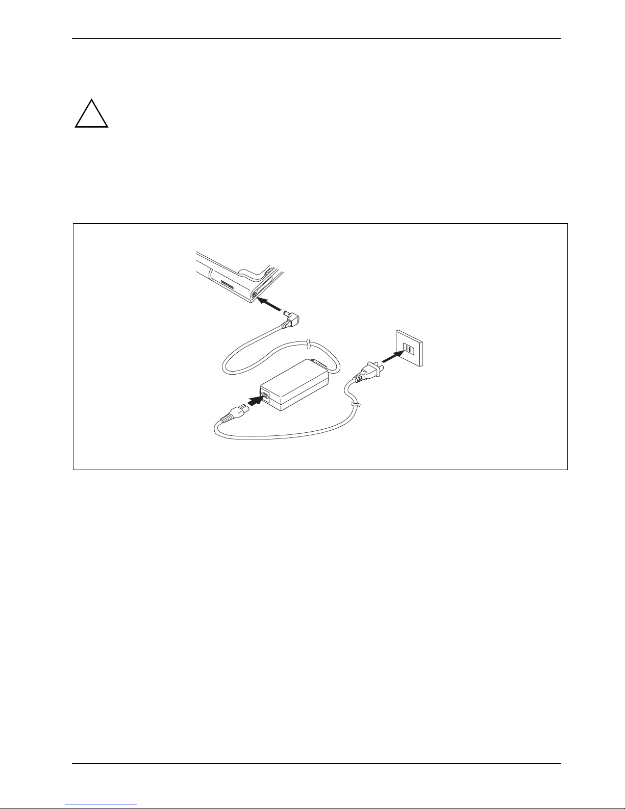
Connecting the mains adapter
Follow the instructions in "
!
The power cable supplied conforms to the requirements of the country in which you
purchased your notebook. Make sure that the power cable is approved for use in the
country in which you intend to use it.
The mains adapter's power cable must only be connected to a mains socket if the
notebook is connected to the mains adapter.
Do not use the mains adapter for other devices.
Do not use a mains adapter that is not specially intended for this notebook.
Selecting a location".
1
3
2
► Connect the mains adapter cable to the DC jack (DC IN) of the notebook (1).
► Connect the power cable to the mains adapter (2).
► Plug the power cable into a mains outlet (3).
A26391-K276-Z226-1-7619, edition 2 15
Page 26

Preparing the notebook for use
1
2
► Press the release button (1), and unfold the LCD screen upwards (2).
The power-on indicator of the notebook is lit.
The battery will charge. On or both battery charge indicators light-up.
The meaning of the various displays can be found in the section "
i
Status indicators".
16 A26391-K276-Z226-1-7619, edition 2
Page 27

Preparing the notebook for use
Switching the notebook on for the first time
!
When you switch your notebook on for the first time, the supplied software is installed and
configured. Due to the fact that this installation procedure must not be interrupted, you
should set aside enough time for it to be fully completed and connect the notebook to the
mains outlet using the mains adapter.
During installation, the notebook may only be rebooted when you are requested to do so!
1
► Slide the ON/OFF switch (1) to the right to switch on the notebook.
The ON/OFF switch returns automatically to its original position.
► During installation, follow the instructions on screen.
Consult the operating system manual if anything is unclear about the requested input data.
On the "Drivers & Utilities" CD/DVD or on the Internet at: http://ts.fujitsu.com/support you will
i
find further information about your system, as well as drivers, tools, updates, manuals, etc.
If you want to use the pen, you will find further information in chapter "
notebook".
Using your
A26391-K276-Z226-1-7619, edition 2 17
Page 28

Preparing the notebook for use
18 A26391-K276-Z226-1-7619, edition 2
Page 29

Using your notebook
This chapter describes the basics for operating your notebook.
Please refer to "
such as a mouse or a monitor to the notebook.
!
Connecting external devices" for instructions on how to connect external devices
Please refer to the notes in the "
Important notes" chapter.
Opening and closing the notebook
Opening the notebook
2
1
► Press the release button (1), and unfold the LCD screen upwards (2).
A26391-K276-Z226-1-7619, edition 2 19
Page 30

Using your notebook
Closing the notebook
► Close the LCD screen onto the bottom half of the notebook with the glass facing inward until
you can feel it lock into place.
Different ways to use your notebook
During your daily work, you can use your notebook as a tablet PC or as a notebook, just as you wish.
The "conversion" is lightning fast and effortless.
Note the direction of rotation in the following description! No guarantee claims can be met
!
for damage caused by turning in the wrong direction.
You must note that the display cannot be turned completely on its own axis!
20 A26391-K276-Z226-1-7619, edition 2
Page 31

Using your notebook
From notebook to Tablet PC
1
► Press the release button, and unfold the LCD screen somewhat upward.
► Rotate the hook from position 1 to position 2.
1
2
► Raise the display into a vertical position.
A26391-K276-Z226-1-7619, edition 2 21
Page 32

Using your notebook
► Hold the screen as low as possible on both sides. Turn the screen to the left or right in the
direction of the arrow. At first you will feel slight resistance and then the display will turn easily
and without friction.
► Turn or twist the display further until it has turned 180° and the hinge latches in.
► Now fold the screen down until the back of the screen is flat on top of the keyboard and the
hook latches in.
The display is now secured in the tablet position.
22 A26391-K276-Z226-1-7619, edition 2
Page 33

Using your notebook
l
l
l
Please note the following points to protect the display from scratches:
● Only use the pen provided with your notebook.
● Replace the pen tip if it is worn (see "
● Avoid contact with any sharp edges such as wrist watches or finger nails.
● Do not lay anything on the display.
Setting the pen").
Select display orientation (portrait or landscape orientation)
You can choose to use either portrait or landscape orientation for the display. Press the Tablet button
to switch from one display orientation to the other.
The display switches automatically to portrait layout when the device is used as a Tablet PC and to
landscape layout when it is used as a notebook.
Windows XP
!
You can change these settings in the Fujitsu menu or under Start – (Settings –) Control Pane
– Tablet and Pen Settings.
Windows Vista
You can change these settings in the Fujitsu menu or under Start – (Settings –) Control Pane
– Mobile PC – Tablet PC – Settings.
Windows 7
You can change these settings in the Fujitsu menu or under Start – (Settings –) Control Pane
– Hardware and Sound – Display – Settings.
Profiles for operating with various different screen modes can be selected via the Fujitsu
i
Tablet Control menu. These profiles have preset standard configurations that can be
modified as desired.
These settings do not just affect the monitor settings on the Tablet PC, but also any
external monitors that may be connected.
A26391-K276-Z226-1-7619, edition 2 23
Page 34

Using your notebook
From Tablet PC to notebook
2
1
► Press the release button (1), and unfold the LCD screen upwards (2).
► Open the display until it is in the vertical position.
24 A26391-K276-Z226-1-7619, edition 2
Page 35

Using your notebook
Note the direction of rotation in the following description! No guarantee claims can be met
i
for damage caused by turning in the wrong direction.
► Hold the display on both sides as far down as possible and then turn the display. It turns easily
and without resistance.
► Turn or move the display further until it has turned 180° and the hinge latches in.
A26391-K276-Z226-1-7619, edition 2 25
Page 36

Using your notebook
To be able to close the notebook again:
1
2
2
► Rotate the hook from position (1) to position (2).
26 A26391-K276-Z226-1-7619, edition 2
Page 37

Using your notebook
Switching the notebook on and off
Switching on the notebook
2
► Slide the ON/OFF switch (1) to the right to switch on the notebook.
The ON/OFF switch returns automatically to its original position.
The power-on indicator (2) lights.
After switch-on a self-test (POST, Power On Self Test) is automatically carried out. Never
!
switch the notebook off during the self-test.
1
A26391-K276-Z226-1-7619, edition 2 27
Page 38

Using your notebook
Windows XP
i
You can configure the ON/OFF switch under Start – (Settings) - Control Panel - Performance
and Maintenance - Power Options - Advanced.
Windows Vista
You can configure the ON/OFF switch under Start - (Settings) - Control Panel – Mobile PC Power Options.
Windows 7
You can configure the ON/OFF switch under Start - (Settings) - Control Panel – System and
Security - Power Options.
If you have assigned a password, you must enter this when requested to do so, in order to
start the operating system. Detailed information on this can be found in the chapter "
notes".
Safety
Switching the notebook off
► Close all programmes and shut down your operating system (please see operating system
manual).
► Slide the ON/OFF switch (1) to the right.
The ON/OFF switch returns automatically to its original position.
► Close the notebook (see "
Closing the notebook").
28 A26391-K276-Z226-1-7619, edition 2
Page 39

Using your notebook
Status indicators
The status indicators provide information about the status of the power supply, the drives and the
keyboard functions etc.
Power indicator
● Indicator is illuminated: The notebook is switched on.
A26391-K276-Z226-1-7619, edition 2 29
● Indicator flashes: The notebook is in sleep mode (Save-to-RAM).
● The indicator is not illuminated: The notebook is switched off or in Save-to-
Disk mode.
Power supply indicator
Indicator is illuminated: The mains adapter is supplying power to the notebook.
Page 40

Using your notebook
Hard disk indicator
Indicator is illuminated: The hard disk drive or the CD/DVD in the optical drive of the
notebook is being accessed.
Battery charging indicator
This description applies for both batteries.
The battery charging indicator shows whether a battery is installed and being
charged.
Battery indicator
This description applies for both batteries.
The battery indicator shows the state of charge of the two installed batteries.
● The indicator lights up blue: The battery is between 50 % and 100 % charged.
● The indicator lights up orange: The battery is between 13 % and 49 %
charged.
● The indicator lights up red: The battery is between 0 % and 12 % charged.
● Indicator flashes orange: The battery state of charge is being checked (for
four seconds after battery installation).
● Indicator flashes red: The battery is faulty.
● The indicator is not illuminated: There is no battery installed.
i
Num Lock indicator
Indicator is illuminated: the
is activated. You can output the characters located at the upper right on the
keys.
Caps Lock indicator
Indicator is illuminated: the Caps Lock key has been pressed. All letters
will be output in uppercase. If a key has several symbols on it
the upper left character will be output.
Scroll Lock indicator
Indicator is illuminated: the key combination
effect that this key has varies between applications.
If you use batteries with a capacity of 5800 mAh, you can also check
the state of charge on the battery itself (see “
5800 mAh“).
Num key has been pressed. The virtual numeric keypad
Fn + Scr has been pressed. The
Batteries with a capacity of
30 A26391-K276-Z226-1-7619, edition 2
Page 41

Using your notebook
Language selection (Windows XP only)
Your notebook is supplied with the Windows XP Tablet PC Edition operating system as a single or
multi-language version (according to your preference).
In the single language version, you are presented with two handwriting recognition input areas, one
for the operating system language and one for English.
In the multi-language version, you have the option of setting the language of the menu texts and the
keyboard as well as that of the handwriting recognition.
With the multi-language models, the default language set for the menu texts, keyboard
i
Specifying the language variant for multi-language models
Selecting the language variant for menu texts
► Click on Control Panel - Date, Time, Language and Regional Options - Language and Regional
and handwriting recognition is English.
Options.
► Set the desired language on the Regional Options tab.
Selecting the language for handwriting recognition and keyboard
► Click on Control Panel - Date, Time, Language and Regional Options - Language and Regional
Options.
► Select the Languages tab.
► Click on the Details button in the Text services and input languages field.
► In the next dialog window, select the Settings register card and click the Add button in the
Installed services field.
► In the next dialog window, select the desired Input area schema.
You can now decide which functions (keyboard layout, handwriting recognition, etc.) the selected
input area schema is to be activated for.
► Mark the desired functions and then confirm your entries by clicking the OK button.
You will find further information in the Windows XP Tablet PC Edition operating system help.
Handwriting recognition under Windows Vista
At present, handwriting recognition under Windows Vista supports the following languages:
English, German, French, Italian, Japanese, Korean, Chinese (traditional and simplified), Dutch,
Spanish, Portuguese and Brazilian.
A26391-K276-Z226-1-7619, edition 2 31
Page 42

Using your notebook
Handwriting recognition under Windows 7
At present, handwriting recognition under Windows 7 supports the following languages:
English, German, French, Italian, Japanese, Korean, Chinese (traditional and simplified), Dutch,
Portuguese, Spanish, Brazilian, Norwegian (Bokmål and Nynorsk), Swedish, Finnish, Danish, Polish,
Rumanian, Serbian (Cyrillic and Latin script), Catalan, Russian, Czech and Croatian.
32 A26391-K276-Z226-1-7619, edition 2
Page 43

Using your notebook
LCD screen
Notes about the LCD screen
If you use the device as a tablet PC, you can also use the LCD screen as a touch screen.
i
High-quality TFT displays with especially bright background lighting are installed in notebooks from
Fujitsu Technology Solutions GmbH. For technical reasons, TFT monitors are manufactured for a
specific resolution. An optimal, clear picture can only be ensured with the correct resolution intended
for the relevant TFT monitor. A monitor resolution which differs from the specification can result in an
unclear picture.
The monitor resolution is understood to be the number of horizontal and vertical pixels (i.e. picture
elements) which make up the monitor display. For example, "UXGA" stands for 1600 x 1200 pixels.
Each pixel consists of three so-called subpixels of the colours red, green and blue. As a result, a
UXGA monitor consists of 1600 x 1200 x 3 = 5.760.000 subpixels.
Frequently used monitor resolutions Number of pixels
Detailed information on this can be found in the chapter Using the Touch Screen.
XGA 1024 x 768
WSXGA (Wide SXGA) 1280 x 768
WXGA 1280 x 800
SXGA 1280 x 1024
HD 1366 x 768
SXGA+ 1400 x 1050
UXGA 1600 x 1200
WUXGA 1920 x 1200
The correct screen resolution for your notebook is specified in the corresponding section in the
chapter "
Current production technology cannot guarantee an absolutely fault-free screen display. A few
isolated constantly lit or unlit pixels (picture elements) may be present. The maximum permitted
number of such faulty pixels is specified in the international standard ISO 9241-3 (Class II).
Example:
A screen with a resolution of 1280 x 800 has 1280 x 800 = 1024000 pixels. Each pixel consists of
three subpixels (red, green and blue), so there are over 3 million subpixels in total. According to ISO
9241-3 (class II), a maximum of 2 light and 2 dark pixels and in addition 5 light or 10 dark subpixels
or an equivalent mix (1 light subpixel counts as 2 dark subpixels) are allowed to be defective.
Technical data".
A26391-K276-Z226-1-7619, edition 2 33
Page 44

Using your notebook
Pixel A pixel consists of 3 subpixels, normally red, green and blue. A
pixel is the smallest element that can be generated by complete
functionality of the display.
Subpixel A subpixel is a separately addressable internal structure within a
pixel that enhances the pixel function.
Cluster (= group of faults) A cluster contains two or more defective pixels or subpixels in a
5 x 5 pixel block.
Background lighting
TFT monitors are operated with background lighting. The luminosity of the background lighting can
decrease during the period of use of the notebook. However, you can set the brightness of your
monitor individually.
Screen settings (when using the device as a notebook)
Adjusting the resolution under Windows XP
You can change the screen resolution under Start – (Settings) - Control Panel - Display - Settings in the
Resolution field.
Adjusting the resolution under Windows Vista
You can change the screen resolution under Start – (Settings) - Control Panel – Mobile PC Personalization - Settings in the Resolution field.
Adjusting the resolution under Windows 7
You can change the screen resolution under Start – (Settings) - Control Panel – Hardware and Sound –
Display - Settings in the Resolution field.
Adjusting the font size
Under Start – (Settings) – Control Panel – Mobile PC – Customization
and a smaller font.
Adjusting the brightness of the display
You can adjust the brightness of your LCD display with the keys Fn + F6 or Fn + F7 : You can
reduce screen brightness with Fn + F6 , or increase it with Fn + F7 .
Synchronising the display on the LCD screen and an external monitor
Your notebook supports simultaneous display on the LCD screen and an external monitor. If the
picture does not appear correctly on the LCD monitor, press the key combination Fn + F10
several times, or switch the external monitor off and then on again. This achieves good picture
synchronisation.
you can choose between a larger
34 A26391-K276-Z226-1-7619, edition 2
Page 45

Using your notebook
Screen settings (when using the device as a Tablet PC)
Adjusting the brightness of the display
You can adjust the maximum and minimum screen brightness directly via the F8 menu under
Screen Brightness.
Synchronising the display on the LCD screen and another monitor
Press the key combination Fn +
.
Using a notebook as a tablet PC
You can execute commands as follows:
● Using the stylus pen (supplied with your device).
● Using your finger (only with Dual Digitizer technology).
Using your finger (only with Dual Digitizer technology)
Everything which you can select or activate using your finger tip can also
i
You can execute certain commands by using your finger tip on the touchscreen of your device.
Selecting menu items (click with the left mouse button)
► Touch the menu item with your finger tip.
Starting programs (double-click with the left mouse button)
be selected or activated using the stylus pen.
► Briefly touch the program icon twice with your finger tip.
Moving objects/windows (drag while holding the left mouse button pressed)
► Place your finger tip directly on the object/window, hold it pressed against the screen and move
the desired object/window.
Opening a context menu (click with the right mouse button)
► Touch the desired item once with your finger tip.
The context menu appears.
Moving the cursor
► Place your finger tip on the screen and move your finger in the direction required.
Scrolling
► Use one finger to quickly stroke across the screen upwards, downwards, left or right to
navigate through the document or to quickly page through the document.
A26391-K276-Z226-1-7619, edition 2 35
Page 46

Using your notebook
Dragging
► Place your finger on an item on the screen and then move your finger without removing it from
the display; this will drag the item to another position. You can also use this movement to page
slowly through documents.
Contracting and extending
► Touch the screen at two edges of an area with two fingers spread apart, then slide the fingers
together to make the area smaller. Spread the fingers to make the area larger.
Rotating
► Touch two corners of a picture on the screen, then turn the picture clockwise or counter-
clockwise at the corners by using your fingers.
Enlarging a view
► Put two fingers on the touch screen and move them apart.
36 A26391-K276-Z226-1-7619, edition 2
Page 47

Using your notebook
Reducing a view
► Put two fingers on the touch screen and move them towards each other.
Using the pen
1 = Pen tip
4
3
2 = Rocker button
3 = Eyelet for pen cord
4 = Eraser
2
1
You can use the pen on your notebook as an electronic writing implement to select items and to
navigate through menu options and programs. Programs that support handwriting recognition also
allow you to write characters directly on the screen with the pen. You can also use the pen as a
drawing tool. You can use the eraser (1) on the pen to delete previously written or drawn inputs.
The notebook pen is retained securely in the pen slot. This ensures that the pen cannot be lost,
regardless of whether you use the notebook as a Tablet PC or as a notebook, or transport it while
travelling. Always replace the pen in its slot when you are not using it.
The notebook is supplied with a pen cord which you can attach to the eyelets on the pen and on the
notebook.
A26391-K276-Z226-1-7619, edition 2 37
Page 48

Using your notebook
Only use the pen provided with your notebook. Do not use substitute pen tips that were not
!
i
specially designed for your notebook. Replace the stylus tip if it is worn. The warranty does
not cover a scratched screen.
While writing, you should watch out that you do not scratch the surface of the display (e.g.
with a wristwatch or bracelet).
The LIFEBOOK T Series pen of your notebook is an electronic instrument which can be
damaged if used improperly. Handle the pen with care.
The following list contains guidelines for proper pen handling:
● Do not gesture with the pen.
● Do not use the pen as a pointer.
● Never use the pen on any other surface than the screen of your notebook.
● Do not try to turn the thumb grip on the pen. The thumb grip is used to place the pen
in its slot and to take it out of the slot.
● Never store the pen with the tip bearing the weight of the pen (e.g., sitting tip down in
a pencil cup). If the pen is stored with the tip pointing down, this may have an
adverse effect on the pen mechanism (particularly under high temperatures). In this
case the pen tip may react as though it is constantly being pressed down. To avoid
damage, the pen should be stored in the pen garage when not in use.
The pen can be influenced by electromagnetic fields (cursor quivers or jumps). There may
be a few areas on the screen where the cursor quivers slightly in spite of pressing the pen
down firmly.
The screen reacts to pen input when the distance between the pen tip and the screen is less than
3 to 5 mm.
With the pen you can run all functions for which you otherwise use a mouse. In addition, you can
very conveniently delete hand-written pen entries using the pen.
Select menu entries (click with the left mouse button)
► Touch the menu entry with the pen tip.
Start programs (double-click with the left mouse button)
► Briefly touch the program symbol twice consecutively with the pen tip.
Move objects/windows (drag with left mouse button pressed)
► Place the pen tip directly on the object/window, hold the pen tip pressed against the screen and
move the desired object/window.
Open context menu (click with the right mouse button)
► Touch the desired element with the stylus and leave the stylus on the element for a moment.
Or
► Press the front part of the rocker button (facing toward the pen tip) and simultaneously touch
the corresponding position with the pen tip.
Moving the cursor
► Hold the pen tip less than 3 to 5 mm from the screen and move the pen.
38 A26391-K276-Z226-1-7619, edition 2
Page 49

Using your notebook
Setting the pen
Windows XP
Under Fujitsu Pen Settings
settings for the pen (pressure sensitivity, assignment and function of the rocker button).
Windows Vista
Under Start – (Settings) – Control Panel – Mobile PC – Pen Settings
panel you can change various settings for the pen (pressure sensitivity, assignment and function of
the rocker button).
Windows 7
Under Hardware and Sound – Pen and Input Devices in the Control Panel you can change various settings
for the pen (assignment and function of the rocker button).
or Tablet and Pen Settings in the control panel you can change various
or Tablet PC Settings in the control
Calibrating the pen
Before using the pen for the first time, you should calibrate it so that the cursor follows the
movements of the pen as accurately as possible. You should also always repeat the calibration if the
co-ordination between the pen and cursor movement deteriorates.
Windows XP
To calibrate, run the Tablet and Pen Settings function in the Control Panel. You need to calibrate both
portrait and landscape formats.
Windows Vista
To calibrate, run the Tablet PC Settings function in the Control Panel. You need to calibrate both
portrait and landscape formats.
Windows 7
To calibrate, run the Hardware and Sound / Tablet PC Settings function in the Control Panel. You need
to calibrate both portrait and landscape formats.
A26391-K276-Z226-1-7619, edition 2 39
Page 50

Using your notebook
Replacing the pen tip
With use, the pen tip may become worn or may pick up foreign particles that can scratch the screen.
A damaged or worn tip may not move freely, causing unpredictable results when using the pen.
If your pen exhibits these problems, you should replace the pen tip. To do so, use the pen tip
removal tool included with your pen.
► To remove the tip; position the tip in the
gap between the two ends of the tip
changer.
► Pinch the two ends of the tip changer
together so that the tip is firmly
clasped (1), then pull it from the barrel.
1
1
► To replace the tip, retrieve one of the new tips that accompanied your pen.
Insert the flat end of the tip into the barrel and push it in firmly until it is seated.
i
If the tip is worn or damaged, discard it.
1
Installing a pen cord
You can attach the pen with a pen cord to prevent accidentally dropping it or losing it.
► Attach the end of the pen cord with the smaller loop to your pen.
Attach the end of the pen cord with the larger loop to your notebook.
40 A26391-K276-Z226-1-7619, edition 2
Page 51

Using your notebook
Using a notebook
Touchpad and touchpad buttons
Keep the touchpad clean. Protect it from dirt, liquids, and grease.
!
The touchpad enables you to move the mouse pointer on the screen. The touchpad buttons allow
you to select and execute commands. The buttons correspond to the buttons on a conventional
mouse.
Do not rest heavy objects (e.g. books) on the touchpad or the touchpad buttons.
1
2
1 = Touchpad
Moving the pointer
► Move your finger on the touchpad.
2 = Touchpad buttons
Selecting an item
► Move the pointer to the item you wish to select.
► Tap the touchpad once or press the left button once.
A26391-K276-Z226-1-7619, edition 2 41
Page 52

Using your notebook
Executing a command
► Move the pointer to the field you wish to select.
► Tap the touchpad twice or press the left button twice.
Dragging an object
► Select the desired object.
► Press and hold the left button and drag the object to the desired position with the finger on the
touchpad.
Switching the touchpad on and off
If you wish, you can connect a USB mouse and then navigate with it instead of the touchpad. In this
case, you can disable the touchpad. This ensures that the touchpad does not react to accidental
touches.
► Press the key combination Fn + F4 to switch off the touchpad.
► Press the key combination Fn + F4 to switch the touchpad back on again.
42 A26391-K276-Z226-1-7619, edition 2
Page 53

Using your notebook
Keyboard
The keyboard of your notebook is subject to continuous wear due to normal use. The
i
The keyboard has been designed to provide all the functions of an enhanced keyboard. Some
enhanced keyboard functions are mapped with key combinations.
The following description of keys and key combinations refers to Windows.
keyboard markings are subjected to particularly high loads. The keyboard markings can
wear off in the course of using the notebook.
7
/
{
7
7
/
{
7
Backspace key
The Backspace key deletes the character to the left of the cursor.
Tab key
The Tab key moves the cursor to the next tab stop.
Enter key (return)
The enter key terminates a command line. The command you have entered is
executed when you press this key.
/
7
7
{
Num
Rol
Alt Gr
7
/
{
7
7
/
{
7
Caps Lock key
A26391-K276-Z226-1-7619, edition 2 43
The Caps Lock key activates uppercase mode (Caps Lock indicator lit). The
Caps Lock function causes all the characters you type to appear in uppercase.
In the case of overlay keys, the character printed on the upper left of the key
appears when that key is pressed.
To cancel the Caps Lock function, simply press the Caps Lock key again.
Page 54

Using your notebook
Shift key
The Shift key causes uppercase characters to appear. In the case of overlay
keys, the character printed on the upper left of the key appears when that key is
pressed.
Alt Gr
Fn
Pause
Break
Alt Gr key
The Alt Gr key allows one to type the characters printed on the lower right of
the keycaps (e.g. { in the case of the 7 key on the German keyboard).
Fn key
The Fn key enables the special functions indicated on overlay keys (see "
Key
combination").
Cursor keys
The cursor keys move the cursor in the direction of the arrow, i.e. up, down, left,
or right.
Pause key
The Pause key temporarily suspends display output. Output will resume when
you press any other key.
Start button
The Start key opens the Windows Start menu.
Menu key
The Menu key invokes the menu for the marked item.
44 A26391-K276-Z226-1-7619, edition 2
Page 55
Using your notebook
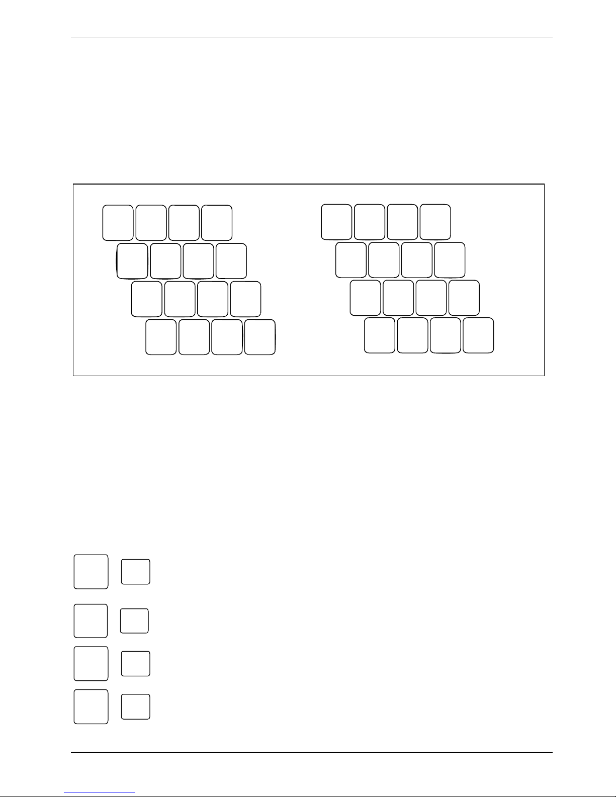
Virtual numeric keypad
The keyboard of your notebook does not have a separate number block. To provide the convenience
of a numeric keypad, your keyboard is equipped with a virtual numeric keypad. The special keys of
the virtual numeric keypad are recognisable by the numbers and symbols printed in the upper right
corner of each key. If you have switched on the virtual numeric keypad, you can output the
characters shown on the upper right of the keys.
/
7
(
{
8
)
[
9
=
]
}
0
7 8 9
IU O P
12
1 = Characters enabled when Num Lock indicator is not lit
2 = Characters enabled when Num Lock indicator is lit
KJ L Ö
M
;
,
µ
:
.
_
-
4 5 6
1 2 3
0
÷
×
-
,
+
Key combination
The following description of key combinations refers to functions when using Microsoft Windows.
Some of the following key combinations may not function in other operating systems and with some
device drivers.
Key combinations are entered as follows:
► Press and hold the first key in the combination.
► While holding the first key down, press the other key or keys in the combination.
F3
Fn
Fn
Fn
Fn
A26391-K276-Z226-1-7619, edition 2 45
+
F4
+
F6
+
F7
+
Switching the loudspeaker on and off
This key combination switches your device's integrated loudspeakers off and
on.
Switching the touchpad on/off
This key combination enables and disables the touchpad.
Decreasing screen brightness
This key combination decreases screen brightness.
Increasing screen brightness
This key combination increases screen brightness.
Page 56

Using your notebook
Fn
Fn
Fn
F8
+
Decreasing the volume
This key combination reduces the volume of the integrated loudspeakers.
F9
+
Increasing the volume
This key combination raises the volume of the integrated loudspeakers.
F10
+
Switching between screen outputs
If an external monitor is connected, the monitor on which the output is to be
displayed can be selected with this key combination.
You can opt to use:
● just the notebook's LCD screen
● just the external monitor
● both the LCD screen and the external monitor.
Press the key combination several times to switch through all possible settings.
If you have connected two external monitors to the port replicator, the following
display outputs are possible:
● just the notebook's LCD screen
● just the external monitor (analog)
● both the LCD screen of the notebook and the external monitor (analog)
● just the external monitor (digital)
● both the LCD screen of the notebook and the external monitor (digital)
You cannot switch output to both external monitors on the Port Replicator via
the key combination.
Ctrl
C
+
Halt an operation
This key combination can be used to halt an operation instantly without clearing
the keyboard buffer.
+
Backtab
This key combination moves the cursor back to the previous tabular
stop.
46 A26391-K276-Z226-1-7619, edition 2
Page 57

Using your notebook
Tablet buttons
Your notebook has five multifunctional tablet buttons. You can navigate on the screen with a simple
press of a button, call preset applications or ones that you have set yourself.
1 = Tablet button
2 = Tablet button
3 = Tablet button
Scroll down
You scroll down in your document with this key.
Additional function, see "
Scroll up
You scroll up in your document with this key.
Additional function, see "
Change screen orientation
When you press the orientation button, the system screen orientation changes
from portrait (vertical) to landscape (horizontal) or from landscape to portrait.
When you would like to use the Tablet PC as an eBook, for example, you would
use the portrait orientation.
When accessing spreadsheets, you would more typically use a landscape
orientation.
Key combination".
Key combination".
4 = Tablet button
5 = Tablet button
A26391-K276-Z226-1-7619, edition 2 47
Page 58

Using your notebook
Key combinations
+
+
Fujitsu Menu calling
Pressing the Fn tablet button twice in quick succession will bring up the Fujitsu
Menu on your screen. The Fujitsu Menu is used to change certain system
settings.
Logon to the system or call the Windows Task Manager
If you hold the
the system again:
– after booting up the system
– after disabling the system
– when returning from power management mode
After log-on, pressing the
Windows Task Manager or - on the network - opens the security window.
Launch the Fujitsu Startcenter
This button starts the Fujitsu Startcenter.
Launch the Mobility Center
This button starts the Mobility Center.
tablet button down for two seconds, you can log back onto
tablet button for two seconds launches the
+
i
Switch the display output to an external monitor (analog)
If you have connected a monitor to the VGA monitor port (directly on the
notebook or via the Port Replicator), you can use this key combination to switch
the display output between the LCD screen of the notebook and the external
monitor.
The tablet button
buttons for the button combination one after the other instead of needing to press them
both at the same time. After pressing the
seconds) to press the second button.
has a practical delay function: This allows you to press the two
tablet button, you have a short time (2 to 3
48 A26391-K276-Z226-1-7619, edition 2
Page 59

Using your notebook
Battery
The battery supplies your notebook with the necessary power during mobile use. You can increase
battery life by enabling the system's power management features.
The life of the battery is dependent on its proper storage, the number of charging/discharging cycles
and the operating temperature of the notebook.
Charging, caring for and maintaining the battery
!
Only use batteries approved by Fujitsu Technology Solutions for your notebook.
Take care not to drop batteries or otherwise damage their casing (fire risk).
If rechargeable batteries develop a fault please stop using them immediately.
Do not touch the contacts of batteries.
Never interconnect the positive and negative terminals of a battery.
Batteries are harmful to the environment. You should dispose of them following guidance
from your local District Council.
Charging the battery
You can charge the battery by connecting the notebook to the mains adapter. The battery can only
be recharged if the ambient temperature of the notebook falls within the permitted temperature
range. The time taken to charge the battery depends on its usage. Information on the battery
charging time is contained in the chapter "
You can increase the life of your battery by allowing it to fully discharge before recharging it again. To
do this, leave your notebook turned on when it is operated with the battery. Once the battery is
running low you will hear a warning alarm. If you do not connect the mains adapter within five
minutes of the warning alarm described above, your notebook will automatically switch off.
Set the power options for your notebook under Control Panel.
Technical data".
i
Storing the battery
Keep the battery pack between 0°C and +30°C (32 and 122 degrees Fahrenheit). The lower the
temperature at which the batteries are stored, the lower is the rate of self-discharge.
If you store rechargeable batteries for a longer period (longer than two months), the battery charge
level should be approx. 30%. To prevent exhaustive discharge, check the charging level of the
batteries at regular intervals.
If you do not use batteries for long periods, remove them from the notebook.
i
Never store batteries in the unit.
Monitoring the battery state of charge
The state of charge of the battery is shown by the battery charging indicator. When you switch on the
device, it takes a few seconds before the battery state of charge is displayed.
A26391-K276-Z226-1-7619, edition 2 49
Page 60

Using your notebook
Windows XP
Windows XP includes a "current charge status indicator" for monitoring the battery capacity. This can
be activated under Start - (Settings) - Control Panel - Power Options.
Windows Vista
Windows Vista includes a "current charge status indicator" for monitoring the battery capacity. This
can be activated under Start - (Settings) – Control Panel – Mobile PC – Power Options.
Windows 7
Windows 7 includes a "current charge status indicator" for monitoring the battery capacity. This can
be activated under Start - (Settings) - Control Panel – Mobile PC - Power Options.
The indicator is then displayed in the task bar as a battery symbol. When you place the mouse
pointer on the battery symbol, the system displays the state of charge of the battery. Please refer to
the Help facility of the operating system for more information.
Batteries with a capacity of 5800 mAh
With these batteries you can check the state of charge directly on the battery itself.
i
► Remove the battery (see "
a
► Press the button (1).
Removing the battery").
1
The LED (a) lights up in one of the following colours:
● The LED lights up green:The battery is between 50 % and 100 % charged.
●
The LED lights up orange:The battery is between 13 % and 49 % charged.
●
The LED lights up red:The battery is between 1 % and 12 % charged.
or
The LED is not lit:The battery is discharged.
50 A26391-K276-Z226-1-7619, edition 2
Page 61

Using your notebook
Removing and installing the battery
Only use batteries approved by Fujitsu Technology Solutions for your notebook.
!
Removing the battery
Never use force when inserting or removing a battery.
Make sure that no foreign bodies get into the battery connections.
1
► Press in the two catches (1), keep them pressed and lift the battery out of the battery
compartment (2).
2
1
Inserting the battery
1
2
► Position the battery at the edge of the casing (1).
► Push the battery into the battery compartment until it locks into position (2).
A26391-K276-Z226-1-7619, edition 2 51
Page 62

Using your notebook
Modules
The design of your notebook enables the flexible use of notebook batteries and drives. The following
modules can be operated in the module bay of your notebook:
● Second battery
● Drive: hard disk: second
● Super multi drive
● Weight Saver
Only use modules designed for your notebook.
!
i
Do not use force when installing or removing the module.
Make sure that no foreign objects enter the module bay.
You can replace modules during operation. This means you do not need to switch off the
notebook.
To replace a module, simply click on the corresponding icon in the task bar and then on
Exit or Select – Exit.
Then you can simply remove the module.
If the module is locked, this can be unlocked via the Control Panel.
52 A26391-K276-Z226-1-7619, edition 2
Page 63

Using your notebook
Removing a module
► Turn the notebook over and place it on a stable, flat and clean surface. If necessary, lay an
anti-slip cloth on this surface to prevent the notebook from being scratched.
Use the corresponding icon in the task bar to stop the module:
► Left-click on the icon.
► Select the module you want to stop and remove.
► Press the Enter key.
Wait for the dialogue box which tells you that it is now safe to remove the module.
1
2
► Carefully slide the eject lever in the direction of the arrow, up to the stop (1).
The module will move out slightly.
► Pull the module out of the module bay (2).
A26391-K276-Z226-1-7619, edition 2 53
Page 64

Using your notebook
Installing a module
► Place the module into the module bay so that the contacts enter first.
► Push the module into the module bay until you feel it locking into place.
Optical drive
You can replace your optical drive with another drive, a battery or a Weight Saver (see "Modules").
Please observe the safety information in the "
!
You may use both 8-cm and 12-cm CDs/DVDs in the combo drive.
When using CDs/DVDs of poor quality vibrations and reading errors may occur.
You should not move the device as long as the CD/DVD in the optical drive is being
accessed (e.g. do not carry the unit around configured as a Tablet PC). You should only
use the CD/DVD drive in a horizontal or vertical orientation.
Do not hold the notebook directly by the drive module bay while the CD/DVD in the optical
drive is being accessed.
Important notes" chapter.
54 A26391-K276-Z226-1-7619, edition 2
Page 65

Using your notebook
Inserting or removing a CD/DVD
The notebook must be switched on.
3
1
2
► Press the insert/eject button (1).
The drive tray will open.
► Pull the drive tray all the way out (2).
► Place the CD/DVD in the drive tray with the label facing upwards or remove an inserted
CD/DVD.
► Push in the drive tray until you feel it lock into place.
A26391-K276-Z226-1-7619, edition 2 55
Page 66

Using your notebook
Manual removal (emergency removal)
In the event of a power failure or damage to the drive it may be necessary to manually remove the
CD/DVD.
a
► Press a pen or a piece of wire (e.g. a paperclip) into the opening (a).
The drive tray is unlocked and opens. You can now pull out the drive tray completely.
ExpressCards
An ExpressCard slot permits operation of an ExpressCard.
Consult the documentation supplied by the ExpressCard's manufacturer and follow the
!
instructions provided.
Never use force when installing or removing an ExpressCard.
Make sure that no foreign objects enter the ExpressCard slot.
56 A26391-K276-Z226-1-7619, edition 2
Page 67

Using your notebook
ExpressCard inserting
2
1
► Press the eject button (1), so that the placeholder for the ExpressCard protrudes slightly from
the notebook.
If the eject button is flush, you must first cause the eject button to release from the notebook
casing. To do this, press the eject button so that it unlatches.
► Pull the placeholder for the ExpressCard (2) out of the slot.
Keep the placeholder for the ExpressCard in a safe place. If you remove the ExpressCard,
i
► Insert the ExpressCard in the slot guide with the connection contacts first.
► Gently push the ExpressCard into the slot until you feel it click into place.
you should reinsert the placeholder into the slot. This prevents foreign matter from getting
into the ExpressCard slot.
Please refer to the documentation for the ExpressCard for driver installation instructions.
i
A26391-K276-Z226-1-7619, edition 2 57
Page 68

Using your notebook
Ejecting a PC card
2
1
► Press the eject button (1) so that the ExpressCard slightly protrudes from the notebook.
If the eject button is flush, you must first cause the eject button to release from the notebook
casing. To do this, press the eject button so that it unlatches.
► Pull the ExpressCard (2) out of the slot.
► Insert the placeholder for the ExpressCard into the slot guide.
► Gently slide the placeholder for the ExpressCard into the slot until you feel it click into place.
58 A26391-K276-Z226-1-7619, edition 2
Page 69

Using your notebook
Memory cards
The slot is suitable for memory cards of the type "Secure Digital I/O", "Memory Stick" and "Memory
Stick PRO".
Inserting a memory card
► Gently push the memory card into the slot until it clicks into place.
Removing a memory card
► Press on the edge of the memory card so that the memory card jumps out of the slot slightly.
► Pull the memory card out of the slot.
Data transfer
UMTS and SIM card (optional)
Depending on the particular equipment of your notebook, it may be equipped with a UMTS
i
!
Inserting the SIM card
► Switch your notebook off.
► Close the LCD screen.
► Unplug the mains plug of the mains adapter from the mains socket.
► Disconnect all cables connected to the notebook.
module which you can use with the aid of a SIM card.
The UMTS module can be switched on and off using the switch for the wireless
components – see "
also use the UMTS Watcher software to define profiles and switch individual wireless
components on or off.
If UMTS reception is not sufficient when using the device as a Tablet PC you can use it is
as a notebook instead – see "
Follow the instructions supplied by the provider of the SIM card.
Wireless LAN/Bluetooth/UMTS radio components (optional)". You can
Select display orientation (portrait or landscape orientation)".
► Open the protective rubber cover over the SIM card slot.
Do not pull on the SIM card lock! The lock could otherwise break off. Always slide the lock
!
A26391-K276-Z226-1-7619, edition 2 59
in the direction of the arrow as shown.
Page 70

Using your notebook
a
1
3
2
► Slide the SIM card lock (a) in the direction of the arrow (1).
The lock (a) controls the power supply for the UMTS module. As long as the lock is open, the
UMTS module is switched off.
► Slide the SIM card as shown into the slot (2) until it engages.
► Slide the SIM card lock (a) in the direction of the arrow (3).
► Close the protective rubber cover over the SIM card slot.
► Reconnect the cables that you disconnected before.
60 A26391-K276-Z226-1-7619, edition 2
Page 71
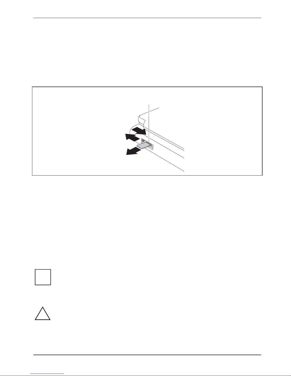
Using your notebook
Removing the SIM card
► Switch your notebook off.
► Close the LCD screen.
► Unplug the mains plug of the mains adapter from the mains socket.
► Disconnect all cables connected to the notebook.
► Open the protective rubber cover over the SIM card slot.
a
3
1
2
► Slide the clip (a) of the SIM card in the direction of the arrow (1).
The clip (a) controls the power supply for the UMTS module. The UMTS module is switched off
while the clip is open.
► Push the SIM card inwards slightly to eject it from the slot.
► Pull the SIM card out of the slot in the direction of the arrow (2).
► Close the protective rubber cover over the SIM card slot.
► Reconnect the cables that you disconnected before.
Wireless LAN/Bluetooth/UMTS radio components (optional)
Depending on the model, radio components (wireless LAN/ Bluetooth/UMTS) may be integrated in
your notebook. The radio components are enabled on delivery.
The UMTS module can also be switched on and off with the switch for the wireless
i
!
components – see "
While the SIM card clip is open the power supply to the UMTS module is interrupted,
which means that the UMTS module is deactivated. It is possible that an error message
may appear on the screen.
The installation of a wireless LAN module not approved by Fujitsu Technology
Solutions GmbH voids the permits (CE!, FCC) issued for this device.
Wireless LAN/Bluetooth/UMTS radio components (optional)".
A26391-K276-Z226-1-7619, edition 2 61
Page 72

Using your notebook
If you switch off the radio components, the Bluetooth module and the wireless LAN
i
Switching on the wireless component
transmission unit (antenna) are also switched off.
You can also use the Wireless Selector software to define profiles and switch individual
wireless components on or off.
You can also deactivate the wireless components individually in the BIOS Setup.
Pay attention to the additional safety notes for devices with radio components provided in
the "Safety" manual.
Details on using Wireless LAN can be found in the online help system included in the
Wireless LAN software.
You can find more information on how to use Bluetooth on the CD you received with your
Bluetooth software.
► Slide the switch in the direction of the arrow to switch the wireless component on.
The Wireless LAN/ Bluetooth indicator is shown in the status indicator panel.
62 A26391-K276-Z226-1-7619, edition 2
Page 73

Using your notebook
Switching off the wireless component
► Slide the switch in the direction of the arrow to switch the wireless component off.
A26391-K276-Z226-1-7619, edition 2 63
Page 74

Using your notebook
Port Replicator
The port replicator (available as an accessory) is a docking device with which you can quickly
connect your notebook to your peripheral devices. For this purpose, the port replicator has standard
ports for monitor, HDMI, LAN and USB devices.
Only use the supplied 100 W mains adapter from Fujitsu Technology Solutions to run the
i
Setting up the Port Replicator
!
port replicator.
Additional information on the port replicator and on the various external devices that can
be connected to it is contained in the chapter "
Select a suitable location for the Port Replicator before setting it up. Consider the following
points when looking for a location:
● Never place the Port Replicator on a soft surface (e.g. carpeting, upholstered
furniture, bed). This can block the air vents of the notebook and cause overheating
and damage.
Connecting external devices".
● Place the Port Replicator on a stable, flat and nonslippery surface. Please note that
the rubber feet may mark certain types of surfaces.
● Never place the Port Replicator and the mains adapter on a heat-sensitive surface.
● Do not expose the Port Replicator to extreme environmental conditions.
Protect the Port Replicator from dust, humidity and heat.
64 A26391-K276-Z226-1-7619, edition 2
Page 75

Using your notebook
Connecting the notebook to the Port Replicator
► Disconnect the mains adapter cable from the DC socket (DC IN) of the notebook.
1
3
2
► Align the docking connectors as shown.
► Press down on the notebook’s rear corners so that it locks into position.
► Connect the mains adapter cable to the DC jack (DC IN) of the Port Replicator (1).
► Connect the power cable to the mains adapter (2).
► Plug the power cable into the mains socket (3).
A26391-K276-Z226-1-7619, edition 2 65
Page 76

Using your notebook
Switching on the notebook via the Port Replicator
► Press the ON/OFF switch on the port replicator to switch the notebook on.
Switching off the notebook via the Port Replicator
► Close all programmes and shut down your operating system (please see operating system
manual).
If the notebook cannot be shut down properly, press the
i
ON/OFF button on the port replicator for about four seconds. The notebook will switch off.
Any unsaved data may however be lost.
66 A26391-K276-Z226-1-7619, edition 2
Page 77

Using your notebook
Disconnecting the notebook from the port replicator
Windows XP
!
If you disconnect the notebook from the Port Replicator during operation, problems can
occur. We recommend that you switch off the notebook beforehand or use the Windows
function Start – Undock.
Windows Vista and Windows 7
If you disconnect the notebook from the Port Replicator during operation, problems can
occur. We recommend that you switch off the notebook beforehand or use the Windows
function Start (Arrow icon
► Pull the release button in direction of the arrow (1).
) – Undock.
2
1
► Lift off the notebook (2).
A26391-K276-Z226-1-7619, edition 2 67
Page 78

Security functions
Security functions
Your notebook enables you to protect your system and personal data in a number of ways against
unauthorised access. By combining these options, you can achieve maximum protection for your
system.
In this chapter you will learn which security functions your notebook is equipped with, which
advantages these functions offer you and how to configure and use them.
Please consider that in the case of improper use, you yourself will also be unable to
!
access your system and your data. Therefore, please note the following hints:
● Back up your data on external data carriers at regular intervals.
● Some security functions need you to choose passwords. Please be sure to note
these passwords, as otherwise you will no longer be able to access your system.
We recommend that you make a note of the passwords and keep them in a safe
place.
If you lose both the user and the supervisor passwords you will need to contact the help
desk. The telephone numbers are contained in the "Service Desk" supplement. Passwords
are not covered by your warranty and a charge will be made for assistance.
A system which was protected using SystemLock can no longer be released.Always create
a backup copy of the SmartCard used.
68 A26391-K276-Z226-1-7619, edition 2
Page 79

Security functions
Brief overview of security functions
You will find comprehensive information on the security configuration of your device
i
Security functions Type of protection Preparation
Kensington Lock Mechanical Fit and lock Kensington
in the "Professional Notebook" manual on the "Drivers & Utilities" CD/DVD
or on the Internet under "http://ts.fujitsu.com/support/".
MicroSaver (accessory).
Fingerprint sensor (device
dependent)
BIOS password protection Password protection for BIOS
Boot from Removable Media Prevent unauthorised boot of an
Owner Information Overlay information from
System Lock The BIOS and the system can
SmartCard reader (device
dependent)
Trusted Platform Module
(device dependent)
Biometric Install the supplied fingerprint
Setup, operating system and
hard disk with supervisor and
user password. The passwords
consist of a maximum of eight
alphanumeric characters.
operating system from external
media (e.g. USB stick, USBCD-ROM drive, etc).
Service desk or owner during
the boot process
only be started with SmartCard
and PIN.
PIN and SmartCard protection
for operating system
Identification and authentication
of the notebook
software.
Specify at least one Supervisor
password in the BIOS Setup and
activate the password
protection for the operating
system and hard disk as
required.
In BIOS Setup, in the menu
Security the option Boot from
Removable Media is processed.
In BIOS Setup, in the menu
Security, the option Owner
Information is processed.
Initialise the SmartCard in the
BIOS.
Install software e.g. SmartCase
Logon+ (accessory). Specify a
password when the SmartCase
Logon+ software is used.
In BIOS Setup a
supervisor password is
configured
A26391-K276-Z226-1-7619, edition 2 69
and the TPM (Security Chip) is
switched on.
Page 80

Security functions
Using the Kensington Lock
The notebook has a Kensington Lock device for the Kensington MicroSaver. With the Kensington
MicroSaver, a sturdy steel cable, you can protect your notebook and Port Replicator from theft. The
Kensington MicroSaver is available as an accessory.
1
► Mount the Kensington MicroSaver on the Kensington Lock device (1) of your notebook.
If you use the rear Kensington Lock device then the eject lever of the module bay is also
i
locked.
70 A26391-K276-Z226-1-7619, edition 2
Page 81

Security functions
Configuring the fingerprint sensor
Your notebook is equipped with a fingerprint sensor. The fingerprint sensor can record the image of a
fingerprint. With the fingerprint software SmartCase Logon+, this image can be processed and used
instead of a password.
1
1 = Fingerprint sensor
► Install the fingerprint software (e.g. SmartCase Logon+) from the supplied CD/DVD in order to
use the fingerprint sensor (1).
A26391-K276-Z226-1-7619, edition 2 71
Page 82

Security functions
Configuring password protection in the BIOS Setup
Before using the various options of password protection for your data security in the BIOS
!
i
Password protection for BIOS Setup (supervisor and user
Setup, please note the following hints:
● Please make sure that you always remember your passwords, as you will not be able
to access your BIOS Setup and/or your system any longer if you forget both the user
password and the supervisor password.
Passwords are not covered by your warranty and a charge will be made for
assistance.
● Back up your data on external data carriers at regular intervals.
Passwords can be up to eight characters long. You can use all alphanumeric characters
and need not distinguish between uppercase and lowercase characters.
password)
We recommend that you print out the following instructions, as these cannot be displayed while
setting the password.
You prevent unauthorised opening of the BIOS Setup with both the supervisor and the user password.
With the supervisor password you have access to all functions of the BIOS Setup, and with the user
password only to part of the functions. You can only set a user password if a supervisor password
has already been assigned.
Please refer to section "
i
operating the BIOS Setup.
Set the supervisor and user passwords
► Call up BIOS Setup and select the Security menu.
► Mark the Set Supervisor Password field and press the Enter key.
With Enter new Password: you are asked to enter a password.
► Enter the password and press the Enter key.
With Confirm new Password you are asked to confirm the password.
► Enter the password again and press the Enter key.
Settings in the BIOS Setup" for a description of calling and
With Notice: With Changes have been saved you receive confirmation that the new password has been
saved.
► To assign the user password, mark the field Set User Password and proceed exactly as when
configuring the supervisor password.
72 A26391-K276-Z226-1-7619, edition 2
Page 83

Security functions
If you do not want to make any other settings, you can exit BIOS Setup.
► Select the Exit Saving Changes option in the Exit menu.
The notebook is rebooted and the new password is effective. If you now want to open the BIOS Setup,
you must first enter your supervisor or user password. Please note that you only have access to a
few BIOS settings with the user password.
Changing the supervisor or user password
► Call up the BIOS Setup again and select the Security menu.
► Highlight one of the fields Set Supervisor Password or Set User Password and press the Enter key.
► Enter your current supervisor or user password.
► Enter your new supervisor or user password.
With Confirm current Password you are requested to confirm the password.
► Enter the password again and press the Enter key.
With Notice: Changes have been saved you receive confirmation that the new password has been
saved.
You can only change the supervisor password when you have logged into the BIOS Setup with the
supervisor password.
Cancelling passwords
To cancel a password (without setting a new password) run the following steps:
► Call up BIOS Setup and select the Security menu.
► Mark the Set Supervisor Password or Set User Password field and press the Enter key.
With Enter current Password you are asked to enter your present password.
► When you receive this request, press the Enter key three times.
► Select the Exit Saving Changes option in the Exit menu.
Your notebook will now restart and the password is cancelled.
With the supervisor password you simultaneously deactivate the user password.
Password protection for starting the operating system
With the supervisor password or the user password you have assigned in the BIOS Setup
Set the supervisor and user passwords"), you can also prevent the operating system
i
(see "
from being started up.
Activating system protection
► Call up BIOS Setup and select the Security menu.
► If you have not yet assigned the BIOS passwords, you can define the supervisor and the user
password now if you wish (see "
► Mark the Password on Boot field and press the Enter key.
► Select the Every Boot entry and press the Enter key.
A26391-K276-Z226-1-7619, edition 2 73
Set the supervisor and user passwords").
Page 84

Security functions
If you do not want to make any other settings, you can exit BIOS Setup.
► Select the Exit Saving Changes option in the Exit menu.
The notebook reboots and you are asked to enter your password (the supervisor or user password).
Deactivating system protection
► Call up BIOS Setup and select the Security menu.
► Mark the Password on Boot field and press the Enter key.
► Select Disabled and press the Enter key.
If you do not want to make any other settings, you can exit BIOS Setup.
► Select the Exit Saving Changes option in the Exit menu.
The notebook reboots and there is no longer any password protection for the operating system.
Password protection for hard disk
The had disk password prevents unauthorised access to the hard disk drives and is
i
checked internally each time the system is booted. The condition for this is that you have
assigned at least the supervisor password.
Activating hard disk protection
► Call up BIOS Setup and select the Security menu.
If you have not yet assigned the BIOS passwords, you can define the supervisor and the user
password now if you wish (see "
► Mark the Hard Disk Security field and press the Enter key.
► In the area Drive0 highlight the field Set Master Password and press the Enter key.
With Enter new Password: you are asked to enter a password.
► Enter the password and press the Enter key.
With Confirm new Password you are asked to confirm the password.
► Enter the password again and press the Enter key.
With Notice: With Changes have been saved you receive confirmation that the new password has been
saved.
► If you wish to enter a password for a second fixed disk (Drive1) , in the area Drive1 highlight
the field Set Master Password and proceed in exactly the same way as for the set-up of the
password for the first fixed disk (Drive0).
The field Password Entry on Boot is set to Enabled in the default setting.
If you do not want to make any other settings, you can exit BIOS Setup.
► Select the Exit Saving Changes option in the Exit menu.
Set the supervisor and user passwords").
The notebook reboots and your hard disk is now protected with a password. The password request
becomes active as soon as the hard disk is installed in another computer and the computer is
started.
74 A26391-K276-Z226-1-7619, edition 2
Page 85

Security functions
Deactivating hard disk protection
To cancel a password (without setting a new password) proceed as follows:
► Call up the BIOS Setup and select the Security menu.
► Mark the Hard Disk Security field and press the Enter key.
► In the area Drive0 mark the field Set Master Password and press the Enter key.
With Enter current Password you are requested to enter your present password.
► When you receive this request, press the Enter key three times.
► From the Exit menu, choose the option Exit Saving Changes.
Your notebook will now restart and the password is removed.
► If you wish to remove the password for the second fixed disk (Drive1), in the area Drive1 mark
the field Set Master Password.
► Proceed exactly as for the removal of the password on the first fixed disk (Drive0).
► From the Exit menu, choose the option Exit Saving Changes.
The notebook reboots and there is no longer any password protection for the hard disk.
Using the SmartCard reader
A SmartCard reader is integrated in your notebook. With the appropriate software you can use your
SmartCard as an alternative to password protection, but also as a digital signature, for encrypting
your e-mails or for homebanking.
SmartCards
SmartCards are not supplied as standard equipment. You can use all SmartCards that comply with
the ISO standard 7816-1, -2, -3 and -4. These SmartCards are available from various manufacturers.
We recommend that you always use two SmartCards. Always keep one of the SmartCards in a safe
place if you carry the other SmartCard with you.
The SmartCard can only be used with a PIN so protection is maintained even when the
i
SmartCard is lost. In order to maximise your security, the SmartCard, which is available as
an accessory, is disabled if three incorrect attempts are made to enter the PIN.
The first time you use your SmartCard you must enter the preset PIN provided by the
SmartCard manufacturer or your system administrator.
Please refer to the software documentation for information about which SmartCards are
supported by the software.
A26391-K276-Z226-1-7619, edition 2 75
Page 86

Security functions
Inserting the SmartCard
Do not use force when inserting and removing the SmartCard.
!
Make sure that foreign objects do not fall into the SmartCard reader.
► Slide the SmartCard into the SmartCard reader with the chip facing upward and at the front.
When the SmartCard is properly inserted, it protrudes by approximately 1.5 cm.
You will find further operating information in the documentation of your SmartCard
i
software (e.g. SmartCase Logon+).
76 A26391-K276-Z226-1-7619, edition 2
Page 87

Security functions
SmartCard SystemLock (optional)
With SystemLock, the device can only be started with an initialised SmartCard (CardOS) and
personal identification number (PIN).The SmartCard and PIN are already checked in the BIOS during
system booting, i.e. before the operating system is booted.
SmartCard SystemLock
Install Single PC:
Install Group PC: [Enter]
[Enter]
Item Specific Help SmartCard SystemLock Not Installed
Installs the security
for this PC, and
creates a new
SystemLock Admin
SmartCard dedicated to
this PC.
SmartCard data will be
overwritten.
A correct SmartCard is
required for a
permanent installation
All new SmartCards have a preset PIN (Personal Identification Number) and PUK
i
Additional software such as SmartCase Logon+ is needed so that the system will also check that the
correct SmartCard is inserted while the system is running.
i
(Personal Unblocking Key).
On CardOS SmartCards, the PIN and PUK are preset to 12345678.
Information on how to deinstall SystemLock can be found under “
A system which was protected using SystemLock can no longer be released.Always create
a backup copy of the SmartCard used.
Uninstall SystemLock“.
A26391-K276-Z226-1-7619, edition 2 77
Page 88

Security functions
Access rights of SmartCards
A new SmartCard initially only has a preset PIN and PUK. Access rights and the customised PIN and
PUK are not assigned until the SmartCard is initialised. The SmartCard type depends on the access
rights assigned to the card, as described below:
● User-SmartCard - system start-up, changing PIN
● Super User SmartCard – Start up system, make changes in BIOS Setup, change PIN
● Service SmartCard – changes in BIOS Setup, operating system boot-up not possible
● Admin SmartCard – Start up system, make changes in BIOS Setup, change PIN, uninstall
SystemLock, initialise SmartCards, unblock SmartCards
The following table shows an overview of the rights associated with each SmartCard type when a
PIN or PUK is entered:
System start-up
call-up BIOS-Setup
Changing own PIN x x x x x
Unblocking own
blocked SmartCards
Unblocking all
blocked SmartCards
Generate user cards x
Deinstalling
SystemLock
User
SmartCard
PIN PUK PIN PUK PIN PUK PIN PUK
x
Super User
SmartCard
Service
SmartCard
Admin
SmartCard
x x
x x x
x* x* x* x
x
x
* In BIOS-Setup preset (Unblock own SmartCard)
Usually there is always an admin SmartCard and at least one User or Super User SmartCard that will
allow a system to be operated.
78 A26391-K276-Z226-1-7619, edition 2
Page 89

Security functions
SmartCard user groups
With SystemLock , user groups can be created. This makes it possible to use a SmartCard to start
several systems. A user group consists of at least two systems. Each user that is allowed to start the
systems is provided with a SmartCard. With this SmartCard the user can select a system to start.
Basic information on setting up user groups
During installation of SystemLock the first device in the user group is set up as "Single PC". The
Admin SmartCard generated during this process is used for the user group generation. During
installation, SystemLock sets up each further device as "Group PC". The existing Admin SmartCard
is plugged in, the information is read in and the device is added to the user group. The Admin
SmartCard decides which user group the device belongs to.
If you use CardOS SmartCards, then SystemLock can be administrated with the Windows Program
"SystemLock Admin". With "SystemLock Admin" you can conveniently manage SystemLock at the
operating system level, construct SystemLock organisational units and groups, create SmartCards
for the organisational units or groups, issue access rights at different levels for user cards, as well as
remotely recreate access rights. The PIN or PUK of your SmartCard or the SmartCards of other
users can be changed by you, and you can also reactivate blocked cards.
For a detailed description, see the "SystemLock Admin" help manual.
Se le c t Sys t em mode: F1
1
Sm ar t Ca rd
PC1
3
PC1
Admi n Card
PC1
PC2
Se le c t Sy st e m mode: F3
3
Admin Card
PC1
PC 1
2
Admi n Card
PC3
PC4
Select System mode: F3
3
Admin Card
PC1
A26391-K276-Z226-1-7619, edition 2 79
Page 90

Security functions
In order that the users receive access to the systems within a user group, SystemLock must now be
used to create User SmartCards or Super-User SmartCards. By using a User SmartCard or SuperUser SmartCard, a user can log into any system within the user group.
Installing SystemLock
During initial installation, the first SmartCard becomes the Admin SmartCard. It has, in combination
with the PUK, all the access rights and should therefore be stored in a safe place. Only an authorised
user (Administrator) may use it, for example to initialise user cards.
If you want to set up a user group, you need an Admin SmartCard. This Admin SmartCard will be
used by you to add further systems to the user group.
Setting up the first system in a user group or a stand-alone
system for use with SystemLock
User group
► Start the device and call up BIOS Setup.
► From the Security menu, choose the option SmartCard SystemLock.
The following SmartCard SystemLock menu will be displayed:
Security
SmartCard SystemLock Item Specific Help
SmartCard SystemLock Not Installed
Install Single PC [Enter]
Install Group PC [Enter]
Enter PIN: [ ]
► Insert a new SmartCard in the reader and press Enter.
Installs the security
from a SystemLock Admin
SmartCard into this PC
without modifying any
data on the SmartCard.
A correct SmartCard is
required for a
permanent installation.
New SmartCards have a preset PUK (see above).
i
► Enter the PUK.
80 A26391-K276-Z226-1-7619, edition 2
You will need to know the PUK assigned to the SmartCard if you want to re-initialise a
previously initialised SmartCard.
Page 91

Security functions
The following appears: ACCESS DENIED = You have entered the wrong PUK. After six failed
attempts, the SmartCard will be blocked and can no longer be used.
► Enter a new PIN at the following prompt:
Enter new PIN:
Confirm new PIN:
Numbers with four to eight digits are acceptable for the new PIN.For security reasons, we
i
► Re-enter the new PIN to confirm.
The following message will be displayed: PIN/PUK do not match = You have confirmed the PIN
incorrectly. You will be requested to re-enter the new PIN and reconfirm.
Please wait a few seconds after confirming the new PIN: SystemLock will be installed.
The following message will be displayed if installation is successful:
recommend that you change the PIN for every SmartCard and use an eight digit number
each time.
Setup Notice
Changes have been saved
[Continue]
► Now press the Enter key. The SystemLock administration menu will be displayed:
Security
SmartCard SystemLock Item Specific Help
SmartCard SystemLock Installed
Uninstall: [Enter]
BIOS Recovery: [Allowed]
SmartCard and Pin [Always required]
SmartCard Initialization
Admin SmartCard [Enter]
SuperUser SmartCard: [Enter]
User SmartCard: [Enter]
Service SmartCard: [Enter]
SmartCard Configuration
Change PIN: [Enter]
Change PUK: [Enter]
Unblock SmartCard: [Enter]
Allows to deactivate
The smartcard security.
ATTENTION:
Always check the BIOS
password settings after
uninstalling
SystemLock.
NOTICE:
Reinstalling a SinglePC
implies re-initializing
all of your smartcards
► For security reasons, the preset PUK should always be changed before removing the new
SmartCard. To do this, under SmartCard Configuration select the Option Change PUK, press the
Enter key and type in a new PUK.
► First enter the preset PUK.
A26391-K276-Z226-1-7619, edition 2 81
Page 92

Security functions
Enter the PUK:
New SmartCards have a preset PUK (see above).
You will need to know the PUK assigned to the SmartCard if you want to re-initialise a previously
initialised SmartCard.
► Enter the PUK.
The following message will be displayed: ACCESS DENIED = You have entered the wrong PUK.
After six failed attempts
the SmartCard will be blocked and can no longer be used.
► Enter the new PUK as follows.
Enter new PUK:
Confirm new PUK:
For the new PUK, 4 to 8-digit numbers are acceptable. We recommend
i
► Re-enter the new PUK to confirm.
The following appears: PIN/PUK do not match = You have confirmed the PUK incorrectly. You will
then be requested to re-enter and reconfirm the new PUK.
Instructions on how to initialise additional SmartCards can be found in Section "
administrator functions".
► If you do not want to initialise any further SmartCards, press Esc and remove the Admin
i
for security reasons that you change the PUK of every SmartCard
and to use an eight digit number.
Carrying out
SmartCard. NEVER write the PIN or PUK on the SmartCard under any circumstances!
Store the SmartCard and PIN/PUK in a secure place and
protect them from unauthorised access.
82 A26391-K276-Z226-1-7619, edition 2
Page 93

Security functions
Adding a system to a user group
► Start the device.
► Call up BIOS Setup and select the SmartCard SystemLock page from the Security menu.
The following SmartCard SystemLock menu will be displayed:
Security
SmartCard SystemLock Item Specific Help
SmartCard SystemLock Not Installed
Install Single PC [Enter]
Install Group PC [Enter]
Enter PIN: [ ]
Installs the security
from a SystemLock Admin
SmartCard into this PC
without modifying any
data on the SmartCard.
A correct SmartCard is
required for a
permanent installation.
► Insert the Admin SmartCard for the user group.
Enter PIN:
► Enter the PIN.
The following message will be displayed: ACCESS DENIED = You have confirmed the PIN
incorrectly. You will then be requested
to re-enter the new PIN and to confirm. After three failed attempts
the SmartCard will be blocked and can only be reactivated using the PUK.
Enter the PUK:
► Enter the PUK.
The following message will be displayed: ACCESS DENIED = You have entered the wrong PUK.
After six failed attempts
the SmartCard will be blocked and can no longer be used.
Please wait a few seconds after entering the PIN and PUK: SystemLock will be installed.
The following message will be displayed if installation is successful:
Setup Notice
Changes have been saved
[Continue]
A26391-K276-Z226-1-7619, edition 2 83
Page 94

Security functions
► Now press the Enter key. The SystemLock administration menu will be displayed:
Security
SmartCard SystemLock Item Specific Help
SmartCard SystemLock Installed
Uninstall: [Enter]
BIOS Recovery: [Allowed]
SmartCard and Pin [Always required]
SmartCard Initialization
Admin SmartCard [Enter]
SuperUser SmartCard: [Enter]
User SmartCard: [Enter]
Service SmartCard: [Enter]
SmartCard Configuration
Change PIN: [Enter]
Change PUK: [Enter]
Unblock SmartCard: [Enter]
Allows to deactivate
The smartcard security.
ATTENTION:
Always check the BIOS
password settings after
uninstalling
SystemLock.
NOTICE:
Reinstalling a SinglePC
implies re-initializing
all of your smartcards
► Generate a user card for the device as described in Section "
Carrying out administrator
functions".
► If you do not want to initialise any further SmartCards, press Esc and remove the Admin
SmartCard.
Carrying out administrator functions
If you have an internal SmartCard reader, you can also switch on the device by inserting the
SmartCard. The following prompt will appear after starting the device:
Insert a SmartCard.
► Insert the Admin SmartCard. The following prompt will be displayed:
Enter PIN.
Select between the options shown:
F2=Setup, F3=Change PIN
► Press the F2 function key to enter BIOS Setup.
► From the Security menu, choose the option SmartCard SystemLock.
The SystemLock administration menu will be displayed:
84 A26391-K276-Z226-1-7619, edition 2
Page 95

Security functions
Security
SmartCard SystemLock Item Specific Help
SmartCard SystemLock Installed
Uninstall: [Enter]
BIOS Recovery: [Allowed]
SmartCard and Pin [Always required]
SmartCard Initialization
Admin SmartCard [Enter]
SuperUser SmartCard: [Enter]
User SmartCard: [Enter]
Service SmartCard: [Enter]
SmartCard Configuration
Change PIN: [Enter]
Change PUK: [Enter]
Unblock SmartCard: [Enter]
Allows to deactivate
The smartcard security.
ATTENTION:
Always check the BIOS
password settings after
uninstalling
SystemLock.
NOTICE:
Reinstalling a SinglePC
implies re-initializing
all of your smartcards
The other SmartCards should either be generated as User SmartCards (System) or as
extended User SmartCards (System and Setup). These then have a
restricted access to the device (see chapter "
Uninstall SystemLock").
► Select the required function. The following prompt will be displayed:
Remove your Admin Card.
Keep the Admin SmartCard in a safe place and
i
protect it from unauthorised access.
► Remove the Admin SmartCard.
Insert a SmartCard.
► Insert the next SmartCard and initialise this as required.
The following prompt will be displayed:
Remove the SmartCard.
Always change the PIN and PUK for each additional SmartCard. The PUK
i
of a SmartCard will be needed if a blocked SmartCard
needs to be unblocked using the Unblock SmartCard function.
► Remove the user SmartCard and label it, e.g. with the name of the user. But NEVER write the
PIN on the SmartCard under any circumstances!
A26391-K276-Z226-1-7619, edition 2 85
Page 96

Security functions
Remote unlock – F4
Requirement:
The device is centrally administered as part of an Organisation Unit and is registered in a
SystemLock admin database. The SmartCard used for the group installation must have been
initialised beforehand using the SystemLock Admin.EXE Windows program (see chapter
SmartCard user groups").
"
In order to enable remote access to a device for a user, or to grant one-time remote access to a
device for a guest or service technician, proceed as follows:
► Start the device.
The Insert a SmartCard prompt will appear.
► Press the F4 key.
The following dialogue box will appear:
SmartCard SystemLock
Org Unit:
PC Group:
I-CODE 1:
I-CODE 2:
Company Department 1
Group 1
0123456789ABCDEF
0123456789ABCDEF
The user must now contact their administrator or their administration hotline
and pass on the data and codes which are displayed.
The administrator then specifies the type of once-only access rights:
User The user can boot the system once.
access
Service One-time access to the BIOS for service purposes, without access to the
access SystemLock functions.
Admin Access to the BIOS and the SystemLock functions, e.g. to unlock
access the device when the associated SmartCard has been lost.
Depending on the definition of the access permissions, an activation code will be created and
communicated to the user over the Hotline. The user must first press the Enter key on the system to
be activated, type in the first half (code 1) of the activation code and confirm with the Enter key. The
dialogue box for entering and confirming the second half (Code 2) of the activation code will appear.
There is no limit to the number of incorrect entries that can be made. If all 32 characters of the
activation code are correctly entered, then the device starts with the rights assigned by the
administrator, as if a corresponding SmartCard were inserted.
86 A26391-K276-Z226-1-7619, edition 2
Page 97

Security functions
The activation code can only be used once to start the device;
i
it becomes immediately invalid, once the device starts to run. If you switch off the device
and want to start it again without your SmartCard, you must first
repeat the procedure described above each time.
Switching on the device with SystemLock
If you have an internal SmartCard reader, you can switch on the device by inserting the SmartCard. If
you use the ON/OFF switch to switch on the device, the following message appears:
Insert a SmartCard.
► Insert your SmartCard.
Enter PIN:
► Enter your PIN.
The following appears: ACCESS DENIED = You have entered an incorrect PIN. After three failed
attempts, the SmartCard will be blocked and can only be enabled again by entering the PUK.
Depending on the rights assigned to your SmartCard, you can select the following functions when
this message is displayed on the screen:
F2=Setup, F3=Change PIN
If your SmartCard has the appropriate rights, you can:
F2 – Start BIOS Setup.
F3 – Change the PIN.
If you do not select a function, the system will boot up.
Start BIOS Setup – F2
A SmartCard with the appropriate rights must be inserted (SuperUser, Service or Admin).
Change PIN
Possible for every initialised SmartCard.
► Press function key F3 .
► Enter the old PIN.
► Enter the new PIN.
For the new PIN, 4 to 8-digit numbers are acceptable.
i
► Confirm the new PIN.
A26391-K276-Z226-1-7619, edition 2 87
For security reasons, we recommend that the PIN of every SmartCard
should be changed and an eight digit number should be used.
Page 98

Security functions
Uninstall SystemLock
► Start the device.
► Follow the instructions as described in Section "
"Uninstall" to uninstall SystemLock.
You can now use the device again without the need for a SmartCard.
Carrying out administrator functions". Select
Error messages
Error messages
This chapter contains error messages generated by the mainboard.
SystemLock – error messages
This chapter describes error messages generated by the SmartCard reader (chipcard reader).
The SmartCard has no access rights to the system.
Boot access
denied
Check your
SmartCard
SmartCard reader
FAILURE
The SmartCard has no access rights to the system.
The SmartCard is either inserted incorrectly or it is not a suitable SystemLock
SmartCard.
An error has occurred on the serial port for the SmartCard reader (chipcard
reader). If this error occurs frequently, the connection between the SmartCard
reader and the mainboard must be checked, or the SmartCard reader must be
replaced. While the error is present, access to the system is blocked.
Non authorized
SmartCard
SystemLock
installation
FAILED:
The SmartCard is
blocked.
Enter the PUK:
The SmartCard cannot be used on this device. The SmartCard has been
configured for a different device.
An error occurred while installing SystemLock. Do not switch off the device;
instead insert the "Flash-BIOS diskette" perform a BIOS-Update and retry the
installation once more.
You have exceeded the maximum allowed number of incorrect PIN entries. The
SmartCard is blocked. Enter the administrator PUK to re-activate the
SmartCard. You must then enter a new User PIN to restart the system.
Trusted Platform Module
This installation need only be performed under Windows XP. TPM is already built into
i
To use the TPM, you must be sure to activate the TPM in the BIOS Setup before the software
Windows Vista.
88 A26391-K276-Z226-1-7619, edition 2
Page 99

Security functions
installation. The condition for this is that you have assigned at least the supervisor password (see
Set the supervisor and user passwords").
"
► Call up BIOS Setup and select the Security menu.
► Select the entry Enabled for Embedded Security Chip to activate the TPM.
If you have activated the TPM, the Clear Security Chip option appears.
You can use this menu item to delete the holder in the TPM. However, you can then no
!
For example, with the TPM activated, data can be generated which can only be read or run on this
device. Support for security protocols, such as SSL (Secure Socket Layer) for Internet connections,
IPSec (LAN encryption), S-MIME (e-mail encryption, WLAN encryption and others) is also possible.
longer access the data you have encrypted on the holder-based keys.
A26391-K276-Z226-1-7619, edition 2 89
Page 100

Security functions
90 A26391-K276-Z226-1-7619, edition 2
 Loading...