

Page 1

Fujitsu Computer Systems
Charge-Only Cradle
User’s Guide
FPCCR05
INSTRUCTIONS
The charge-only cradle is designed for a desktop, counter
top, or wall-mounted installation where a quick connection
to a DC power source is needed. The Tablet PC can be
placed in the charge-only cradle and used while external DC
power is supplied to the cradle. The connector pins on the
cradle are “high-usage” type pins and are designed to withstand a large number of insertions and removals. The cradle
includes two adapters that fit over the Tablet PC’s DC-in
port to make it more suitable for the high-usage environment.
The cradle can accommodate a Tablet PC with a standard
main battery or an optional high-capacity battery. A removable spacer is included with the cradle to make the cradle
usable with either battery.
Page 2
Installing the System in the Cradle
To install the Tablet PC in the charge-only cradle, you must
first attach a DC adapter to the system’s DC port.
Attaching the DC Adapter
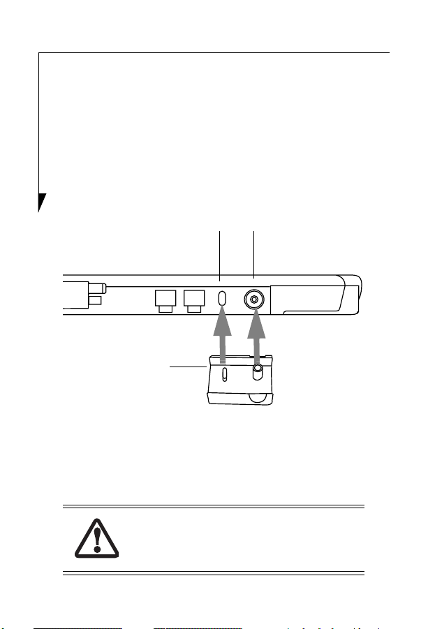
1. Hold your system so that the left side (when viewed in
portrait mode) with the DC-in port is facing you
(Figure 1).
Lock Slot DC-In Port
DC Adapter
Figure 1. Attaching the DC Adapter
2. Attach the DC adapter to the system by inserting the
plugs inside of the adapter into the lock slot and the
DC-in port on the system (Figure 1). The adapter
should fit snugly into position.
When powering your charge-only cradle, use
only the AC Adapter that is compatible with
your Tablet PC.
2
Page 3
Verifying Battery Size
Determine whether your Tablet PC has a standard main
battery or an optional high-capacity main battery installed.
■
If your Tablet PC has a high-capacity main battery
installed, remove the spacer (Figure 2) that is located
inside the cradle on the right. Pull it upwards to
remove it from the slot.
Stow the spacer in the spacer tray inside the chargeonly cradle so that it will be available for occasions in
which you use the standard battery. To remove the
spacer from the tray, press down on the right side of the
spacer, causing its left side to lift up.
■
If your Tablet PC has a standard main battery installed,
be sure the spacer is installed in the slot on the inside
right of the cradle (Figure 2).
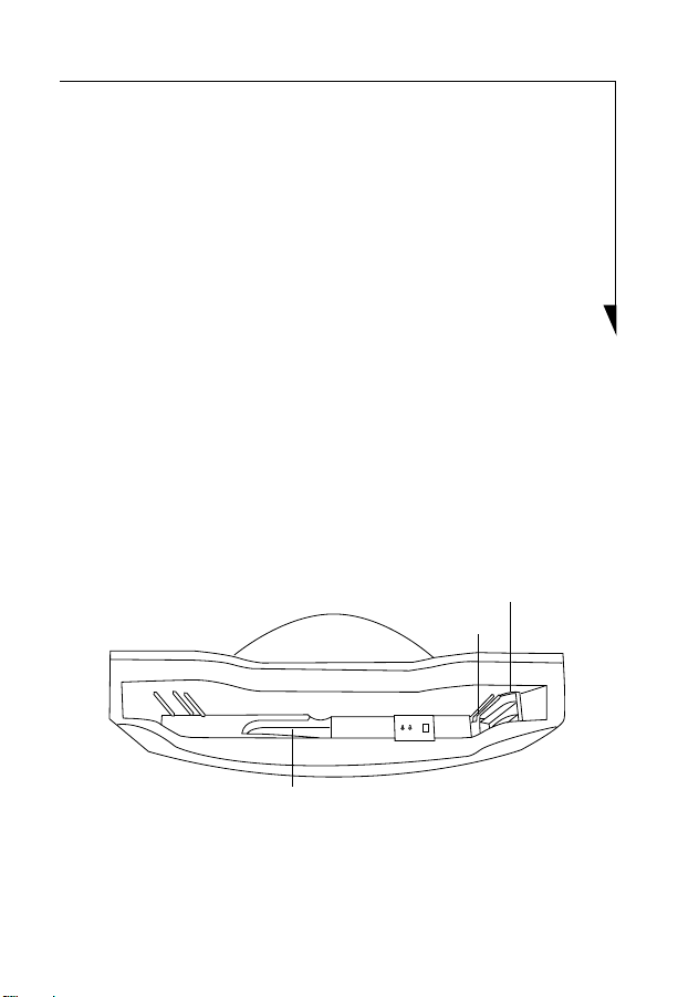
Spacer
Slot
Spacer Tray
Figure 2. Inside the Charge-Only Cradle
3
Page 4

Installing the Tablet PC in the Charge-Only Cradle
1. Place the cradle on the flat, stable location in which it
will be used
.
2. After verifying that the spacer is configured correctly
and the DC adapter is attached to the DC-in port, hold
the system in landscape mode, with the buttons
arranged across the top (Figure 3).
Figure 3. Installing the Tablet PC in the Cradle
3. Insert the tablet into the cradle until it rests securely on
the bottom of the cradle.
4. Plug the system AC adapter into the DC-in port on the
right side of the cradle, and the other end into a power
outlet.
4
Page 5

DC-In Port
Figure 4. DC-In Port on Cradle
Removing the Tablet PC from the Charge-Only Cradle
While holding the base of the cradle with one hand, gently
pull the Tablet PC out of the cradle.
Mounting the Cradle on a Wall
The charge-only cradle is designed so that it can be easily
mounted to a wall. The cradle consists of two large components: a base and a cradle. Before mounting the cradle to a
wall, the base component must be removed.
To separate the two components, perform the following
steps:
1. Holding the cradle portion with one hand and the base
portion with the other, lift the cradle section while
pushing down on the base section until the two halves
disengage at the separation point (Figure 5).
5
Page 6

Cradle Section
Separation Point
Base
Section
Figure 5. Separating the Cradle
2. Once disengaged, store the base section in a safe place
for future use.
3. The back of the cradle section has four holes for wall-
mounting and six holes for reattaching the base section.
Wall-mount Holes
Base Attachment Holes (6 total)
6
Figure 6. Wall-Mount holes
Page 7

4. Attach four screws (sheet metal, #14 panhead, zincplated recommended, or equivalent) to the wall as
shown in Figure 7. The screw heads should extend from
the wall approximately 0.25”.
12.25" (311.0 mm)
4.26" (108.0 mm)
Figure 7. Wall-mount Screw Dimensions
5. Align the wall-mount holes on the cradle (Figure 6)
with the mounting screws so that the screw heads
extend into the round portions of the wall-mount
holes. (Figure 8)
Slotted portion
Round portion
Figure 8. Wall-mount Hole
6. When the four screw heads are aligned, press the cradle
firmly against the wall and slide it to the right and
downwards, so that the screws move to the top of the
slotted portion of the holes, locking it in place.
7
Page 8

Fujitsu Computer Systems Corporation
1250 E. Arques Avenue (M/S 122)
Sunnyvale, CA 94085
For more information, visit our Web site
at: us.fujitsu.com/computers
For technical support call:
1-800-8Fujitsu (1-800-838-5487)
or e-mail us at: 8fujitsu@us.fujitsu.com
Fujitsu and the Fujitsu logo are registered trademarks of Fujitsu, Ltd. All other trademarks
mentioned herein are the property of their respective owners. We cannot guarantee the
accuracy of the contents of this document. We disclaim liability for errors, omissions or
future changes.
© 2004 Fujitsu Computer Systems Corporation. All rights reserved.
8
FPC58-1087-01
 Loading...