

Page 1

Connectivity
P eripherals
User’s Guide
Point 510
Point 1600
Page 2

Page 3

Connectivity
P eripherals
User’s Guide
Point 510
Point 1600
Page 4

Fujitsu Personal Systems, Inc. has made every effort to ensure the accuracy and
completeness of this document. However, because ongoing development efforts are
continually improving the capabilities of our products, we cannot guarantee the
accuracy of the contents of this document. We disclaim liability for errors, omissions,
or future changes herein.
Point 510 and Point 1600 are trademarks of Fujitsu Personal Systems, Inc.
All other products are trademarks or registered trademarks of their respective
companies.
Copyright 1999
Fujitsu Personal Systems, Inc.
No part of this publication may be copied, reproduced, translated, stored, or transmitted without
the express written consent of Fujitsu Personal Systems, Inc.
Page 5

Agency Comp lian ce
FCC Notice
This equipment has been tested and fo und to comply with the limits for a Class B digital
device, pursuant to Part 15 of the FCC rules. These limits are designed to provide reasonable
protection against harmful interference in a residential installation. This equipment generates,
uses, and can radiate radio frequency energy and, if not installed and used in accordance with
the instructions, may cause harmful interference to radio communications. However, there is
no guarantee that interference will not occur in a particular installation. If this equipment does
cause harmful interference to radio or television reception, which can be determined by
turning the equipment off and on, the user is encouraged to try and correct the interference by
one or more of the following measures:
• Reorient or relocate the receiving antenna.
• Increase the separation between the equipment and receiver.
• Connect the equipment into an ou tlet on a circuit different from that to which the receiver
is connected.
• Consult the dealer or an experienced radio/TV technician for help.
Shielded interconnect cables must be emplo yed with this equipment to insure compliance
with the pertinent RF emission limits governing this device.
Changes or modifications not expressly approved by Fujitsu Personal Systems, Inc., could
void the user’s authority to operate the equip ment.
Canadian DOC Compli ance
This digital apparatus does not exceed the Class B limits for radio noise emissions from
digital apparatus as set out in the radio interference regulations of the Canadian Department of
Communications.
Le présent appareil numérique n’émet pas de bruits radioélectriques dépassant les limites
applicables aux appareils numériques de class e B prescrites dans le règlement sur le
brouillage radioélectrique édicté par le Ministère des Communications du Canada.
iii
Page 6

iv
Page 7

Tabl e of Contents
About This Guide
Related Documentat ion ............................................................................. viii
Organization................................................................................................ viii
Chapter 1
Getting Started
Introduction to Connectivity Peripherals................................................ 1-1
Portable Port Expander.............................................................................. 1-2
Port Replicator............................................................................................. 1-3
High-Usage Cradle ..................................................................................... 1-4
High-Connectivity Cradle ........................... .............................................. 1-6
Wall-Mount Cradle............................ ......................................................... 1-8
Charge-Only Cradle ................................................................................... 1-9
Folding Desk Stand..................................................................................... 1-10
Chapter 2
Using Point 510/Point 1600 Connectivity Peripherals
Portable Port Expander.............................................................................. 2-2
Attaching the Portable Port Expander......................................... 2-3
Disconnecting th e Portable Port Expander................................. 2-5
Port Replicator............................................................................................. 2-6
Inserting the Pen Tablet ................................................................. 2-7
Locking and Unlocking the Port Replicator................................ 2-9
Removing the Pen Tablet From the Port Replicator ............... ... 2-10
Attaching the Port Replicator to the Desk Stand........................ 2-10
Setting Up the Desk Stand......................................................... 2-11
Attaching the Port Replicator to the Desk Stand.................... 2-12
Detaching the Port Replicator from the Desk Stand.................. 2-13
Folding the Desk Stand............ .................................................. 2-13
High-Connectivity Cradle ........................... .............................................. 2-14
Inserting the Pen Tablet ................................................................. 2-14
Locking and Unlocking the High-Connectivity Cradle............ 2-16
Adjusting the Viewing Angle ....................................................... 2-17
Removing the Pen Tablet............................................................... 2-18
High-Usage Cradle ..................................................................................... 2-18
Inserting the Pen Tablet ................................................................. 2-19
Locking and Unlocking the High-Usage Cradle........................ 2-21
Adjusting the Viewing Angle ....................................................... 2-21
Removing the Pen Tablet............................................................... 2-22
Wall-Mount Cradle............................ ......................................................... 2-23
Opening the Wall-Mount Cradle.................................................. 2-23
Closing the Wall-Mount Cradle.................................................... 2-24
Inserting the Pen Tablet ................................................................. 2-24
Locking and Unlocking the Wall-Mount Cradle........................ 2-26
v
Page 8

Removing the Pen Tablet............................................................... 2-27
Charge-Only Cradle ................................................................................... 2-28
Inserting the Pen Tablet ................................................................. 2-28
Removing the Pen Tablet............................................................... 2-28
Synchronizing Cradle Lat ches........................ .... ...................................... 2-29
Chapter 3
Care and Maintenance of Connectivity Peripherals
Cautions........................................................................................................ 3-1
Cleaning Connectivit y Peripher als........................................................... 3-2
vi
Page 9

About This Guid e
This guide provides operating instructions for the following Point 51 0 and Point 1600
pen tablet connectivity peripherals. Note that several of the peripherals are available
in locking and non-locking versions.
Part Name
Portable port expander
Port replicator
High-connectivity cradle
High-usage cradle
Wall-mount cradle
Charge-only cradle
Locking/
Non-Locking
N/A
Locking
Non-Lockin g
Locking
Non-Lockin g
Locking
Non-Lockin g
Locking
Non-Lockin g
N/A
FPSI Order Number
FMW26CR5
FMW26CR3
FMW26CR23
FMW26CR2 *
FMW26CR22 *
FMW26CR1 *
FMW26CR21 *
FMW26CR4 *
FMW26CR24 *
FMW26CR10 *
Folding desk stand
* This guide provides instructions for using the Point 510 and Point 1600 pen
tablets with these cradles at the work site. For details on installing these
cradles and connecting peripheral devices, refer to the Connectivity
Peripherals Ins tallation Guide: Point 510, Point 1600 or contact your reseller.
N/A
FMWDS3
vii
Page 10

Related Document ation 0
The following manuals provide additional information on t he Point 510 and Point
1600 pen tablets and peripherals.
Point 510 User’s Guide
This manual gives instructions on using the Point 510 pen tablet.
Point 1600 User’s Guide
This manual gives instructions on using the Point 1600 pen tablet.
Connectivity Peripherals Installation Guide: Point 510, Point 1600
This manual provides details on ass e mbling and installing Point 510 and Point
1600 connectivity peripherals.
Connectivity Peripherals Product Reference: Point 510, Point 1600
This 1-page sheet is shipped with Point 510 and Point 1600 connectivity
peripheral components to illustrate the individual components required to
assemble different connectivity peripherals.
Organization 0
This guide is organized as follows:
• Chapter 1: Getting Started
This chapter provides an introdu ction to the Point 510 and Point 1600
connectivity peripherals and their features.
• Chapter 2: Using Point 510 and Point 1600 Connectivity Peripherals
This chapter gives instructions on using each o f the Point 510 and Point 1600
Connectivity Peripherals.
• Chapter 3: Care and Maintenance of Connectivity Peripherals
This chapter provides information on maintaining and handling your
connectivity peripherals.
viii
About This Guide
Page 11

Chapter 1
Getting Started
This chapter provides an overview of the Point 510 and Point 1600 connectivity
peripherals and their features.
Introduction to Connectivity Peripherals 1
The Point 510 and Point 1600 connectivity peripherals provide additional interface
capabilities and other additional functionality to your pen tablet system. In general,
connectivity peripherals are designed to connect to the pen tablet in one simple
operation and provide connections to various computer equipment. Table 1-1
provides a quick look at the interfaces provided by each of the connectivity
peripherals. The specific sections comprising the rest of the chapter outli ne the
interfaces and functionality of each of the peripherals.
Serial Port A
Serial Port B
PS/2-st yle Mouse
PS/2-st yle Keyboard
Parallel Port
Floppy Drive Port
Video Po rt
DC Power Input
Table 1-1. Ports Available in Connectivity Peripherals
Expander
Portable Port
Port Replicator
High-Usage Cradle
Cradle
High-Connectivity
✔✔ ✔
✔✔ ✔
✔* ✔✔✔
✔✔✔✔
✔✔ ✔
✔✔ ✔
✔✔ ✔
✔✔✔✔✔
Cradle **
Wall-Mount
Cradle
Charge-Only
* The PS/2-style port on the PPE can be used for either a mous e or ke yboard o n the P oin t 1600;
on the Point 510, it can only be used for a mouse.
** Altho ugh the wall-mount cradle includes a mouse port, the mouse port is not used in the
wall-mount cradle.
Introduction to Connectivity Peripherals
1-1
Page 12
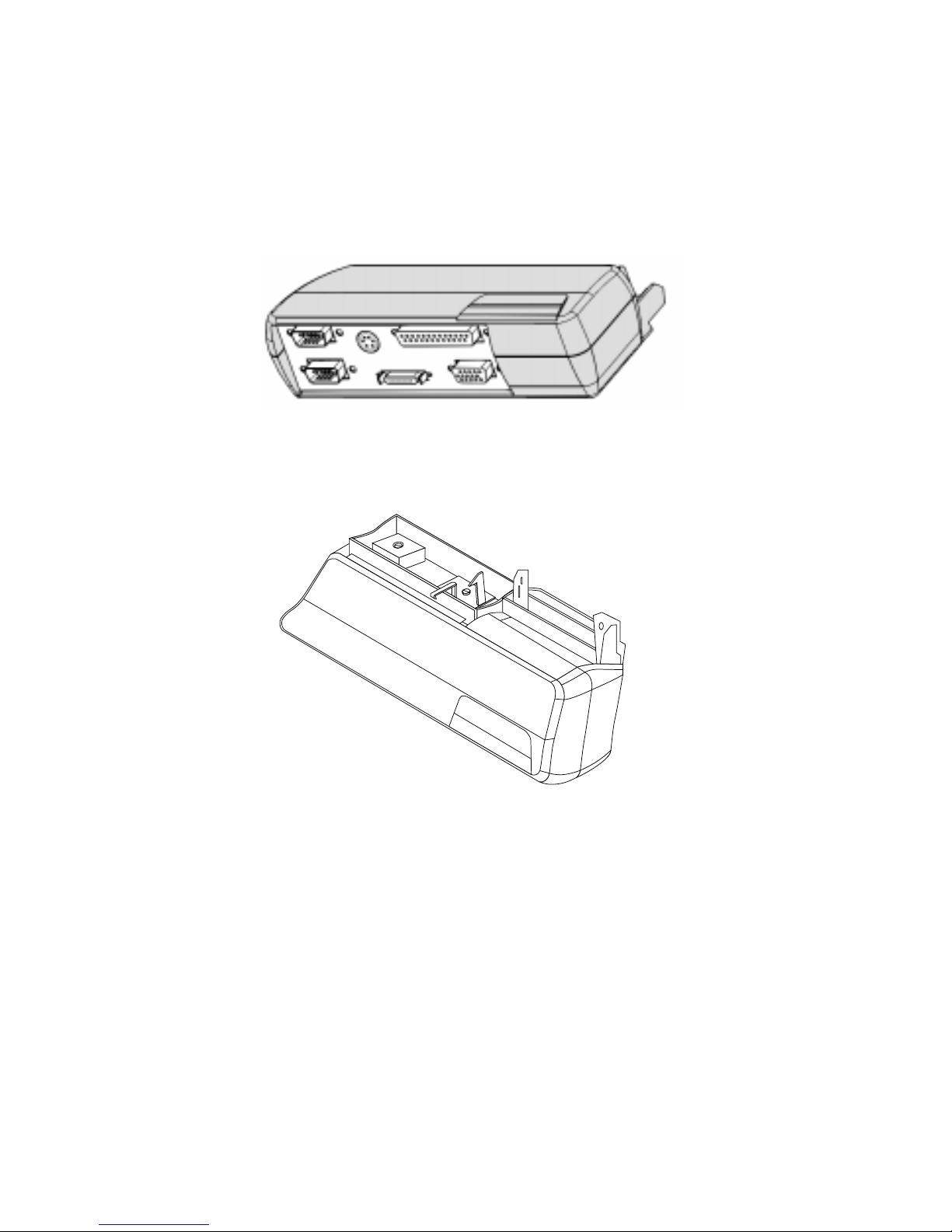
P ortable Port Expander 1
The Point 510/Point 1600 portable port expander is best suited fo r mobile computing
tasks when a quick and temporary connection to peripheral computer equipment is
needed and the pen tablet alone does not provide the necessary connect ivity.
Figure 1-1. Portable Port Expander - Bottom View
Figure 1-2. Portable Port Expander - Top View
The portable port expander provides the following interfaces for connection to
peripheral computer equipment:
• Serial port A
• Serial port B
• PS/2-style mouse/keyboard port (This port can only be used with a mouse on the
Point 510; on the Point 1600, it can be used either with a mouse or a keyboard).
• Parallel port
• Floppy disk drive port
• Video port
1-2
Getting Started
Page 13
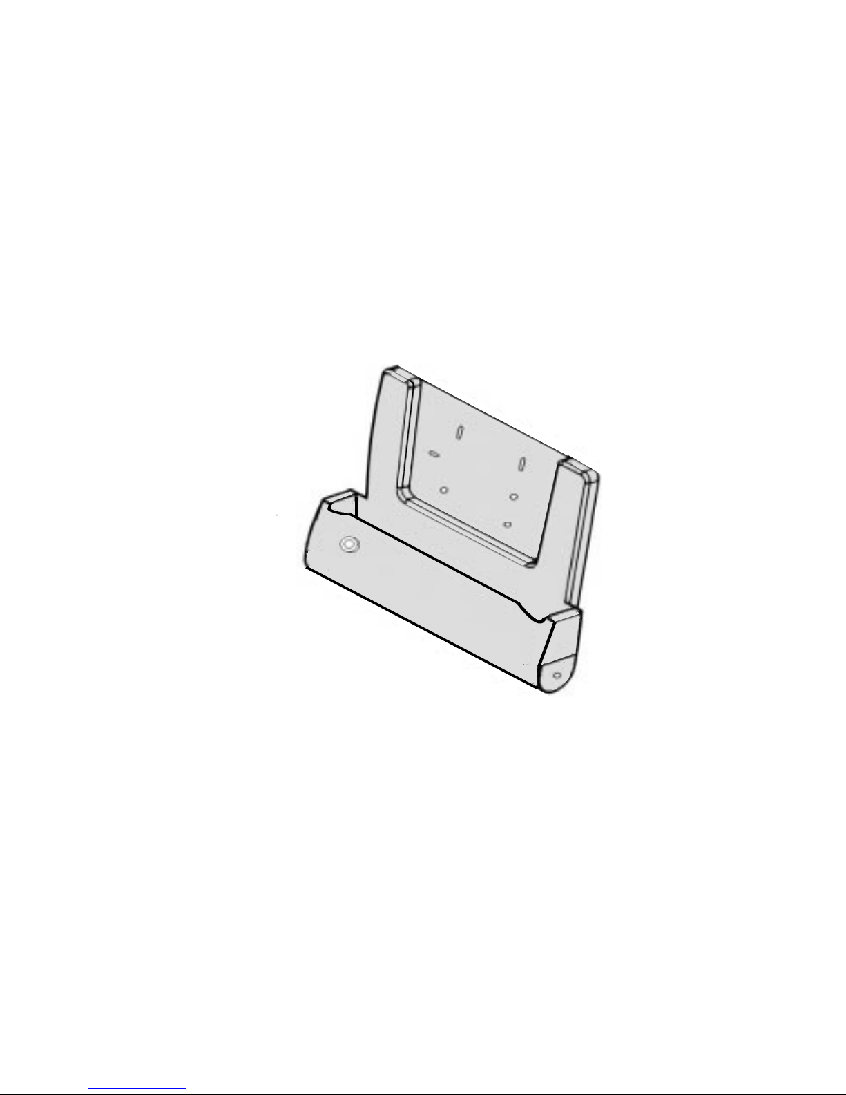
P ort Replicator 1
The Point 510/Point 1600 port replicator is best suited for use on a desk top and is
designed for use with the FMWDS3 folding desk stand. The port replicator adds
connectivity that is not built into the Point 510 and Point 1600 pen tablets. Typically,
the port replicator is connected to peripheral computer equipment and the pen tablet
is then inserted in the port replicator when the peripheral equipment is needed.
Note: The port replicator fo r the Point 510 and the Point 1600 is available in two
versions: locking and non-locking. The locking version includes a lock (also called
a “tubular lock” elsewh ere in this manual) to secure the pen tablet to the port
replicator. The illustrations and procedures provided in this document address the
locking version.
Figure 1-3. Point 510/Point 1600 Port Replicator
The port replicator provides the following peripheral interfaces and connectors:
• Serial port A
• Serial port B
• Parallel port
• Floppy disk drive port
• Video port
• PS/2-style keyboard port
• PS/2-style mouse port
• DC power input
Port Replicator
1-3
Page 14

High-Usage Cr ad le 1
The Point 510/Point 1600 high-usage cradle is designed for environments where the
pen tablet is frequently inserted into and removed from the cradle. The high-usage
cradle is equipped with special “high-usage” connector pins that are designed to
withstand a much higher number of pen tablet insertion and removal operations.
This cradle is best suited for desk- or counter-top installations where the cradle
remains stationary.
Note: The high-usage cradle for the Point 510 and the Point 1600 is available in two
versions: locking and non-locking. The locking version includes a tubular lock to
secure the pen tablet into the cradle. The illustrations and procedures provided in
this document address the locking version
The high-usage cradle provides connections for the following interfaces:
• PS/2-style keyboard
• PS/2-style mouse
•DC input
1-4
Getting Started
Figure 1-4. High-Usage Cradle
Page 15
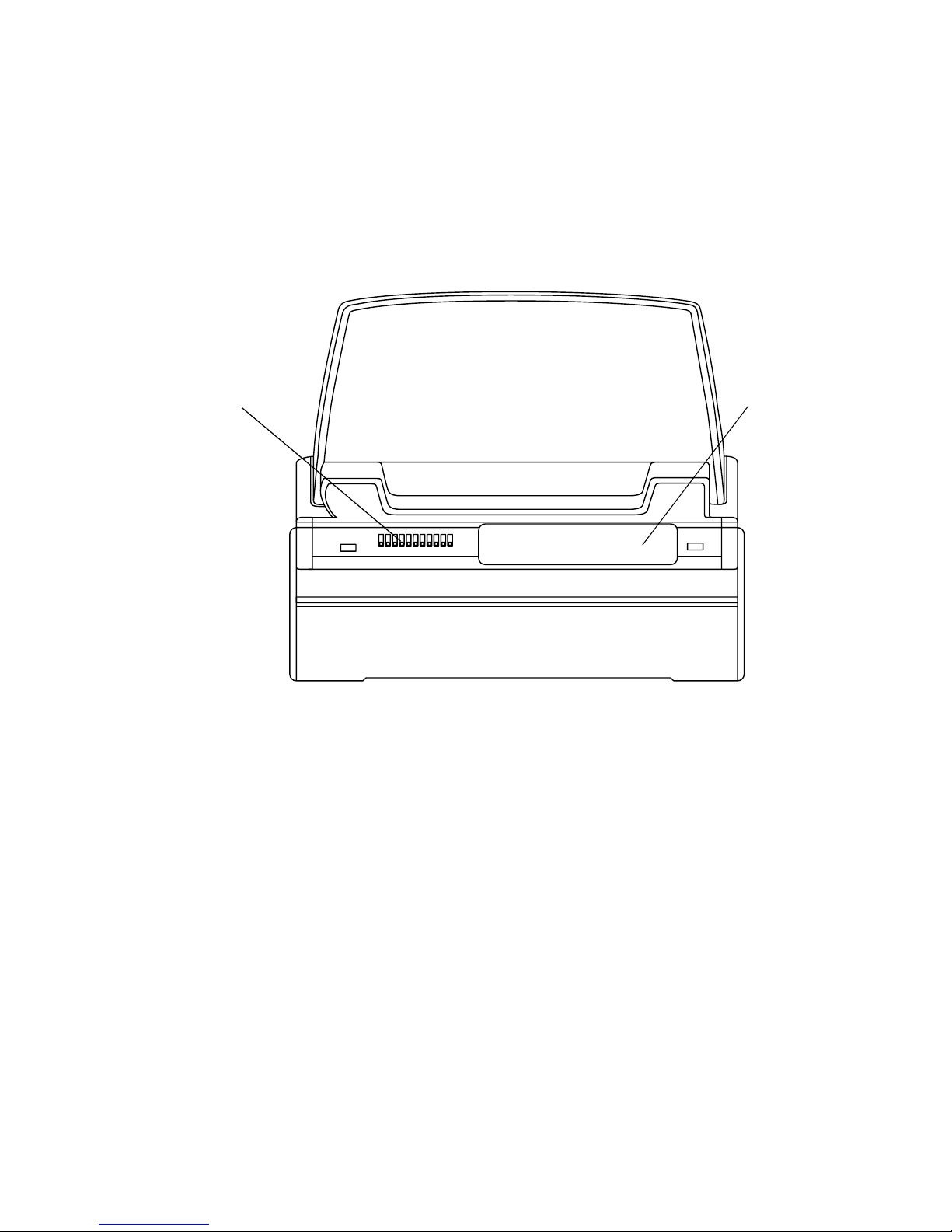
The high-usage cradle is similar in appear ance to the high-connectivity cradle. To
distinguish between the two, observe that the high-usage cradle is equipped only
with high-usage connector pins and does not have a connector that contacts the
system interface port on the pen tablet; the high-connectivity cradle has both. The
following figure shows the location of the high-usage connector pins on the
high-usage cradle.
High-usage
connector pins
No connector
in this area
Figure 1-5. Identifying the High-Usage Cradle
High-Usage Cradle
1-5
Page 16

High-Connectivity Cr ad le 1
The high-connectivity cradle provides several additional peripheral interfaces that
neither the high-usage cradle nor the pen-tablet alone provide. This cradle is best
suited for desk- or counter-top installations where the cradle remains stationary.
Note: The high-connectivity cradle for the Point 510 and the Point 1600 is available in
two versions: locking and non-locking . The locking version includes a tubular lock
to secure the pen tablet into the cradle. The illustrations and procedures provided
in this document address the locking version.
Figure 1-6. High-Connectivity Cradle
The high-connectivity cradle provides the following peripheral connectors:
• Serial port A
• Serial port B
• Parallel port
• Floppy disk drive port
1-6
Getting Started
Page 17
• Video port
• PS/2-style keyboard port
• PS/2-style mouse port*
• DC power input
* The high-connectivity cradle, due to its modular design, is equipped with
two mouse ports. Note that only one mouse port can be used at a time.
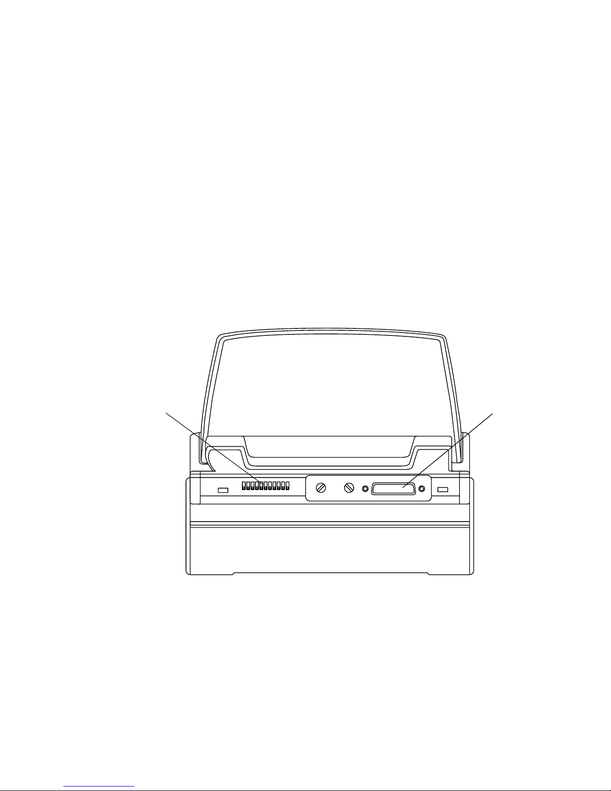
Note that the high-connectivity cradle is similar in appearance to the high-usage
cradle. To distinguish the two, observe that the high-connectivity cradle is equipped
with a system interface connector; the high-usage cradle does not have the connector.
Figure 1-7 shows the location of the s ystem interface connector on the
high-connectivity cradle.
High-usage
Connect or Pins
120-pin
Connector
Figure 1-7. Identifying the High-Connectivity Cradle
High-Connectivity Cradle
1-7
Page 18

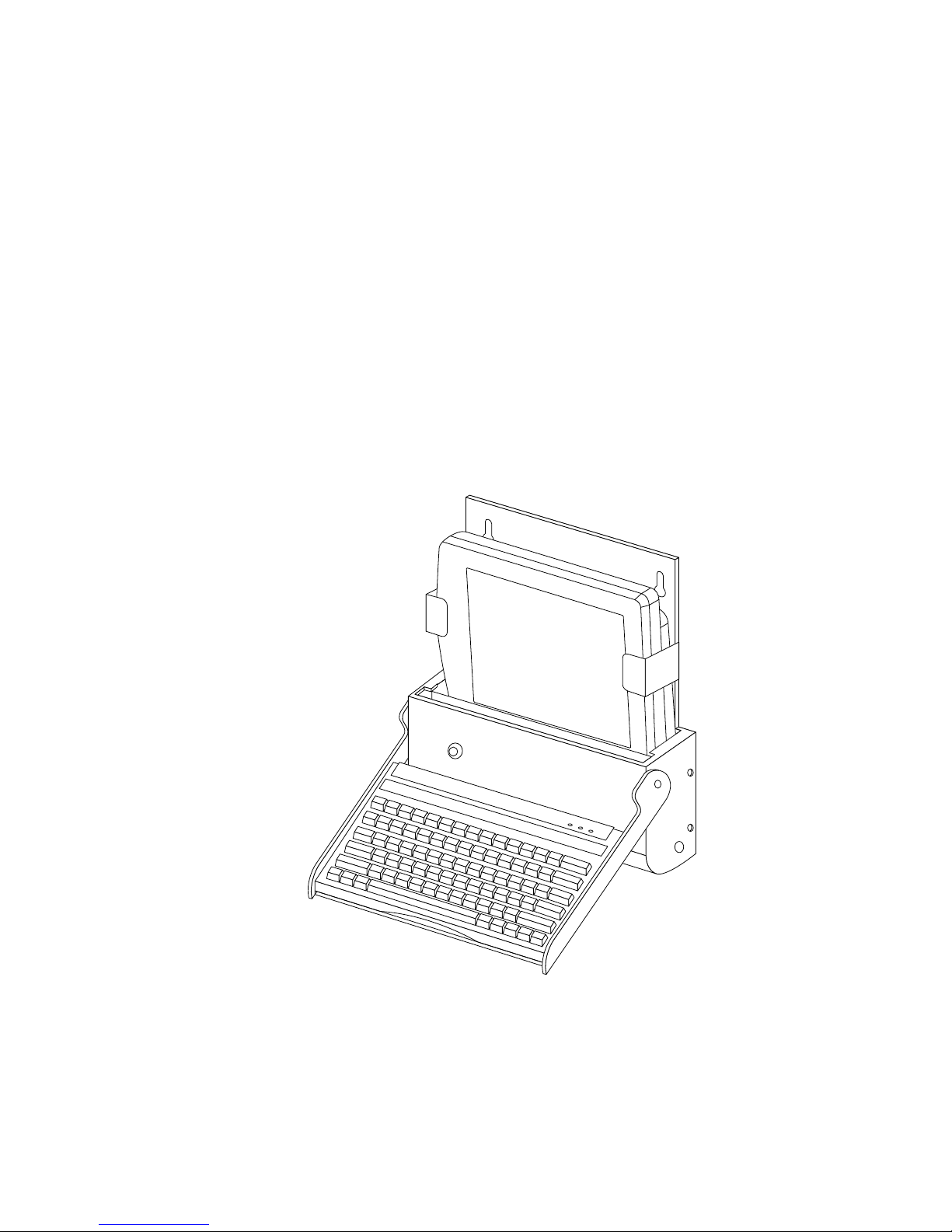
W all-Mo unt Cr adle 1
The wall-mount cradle is designed to be installed on a wall. It has a built-in keyboard
tray, and allows the pen tablet to be charged as it is being used.
Note: The wall-mount cradle for the Point 510 and the Point 1600 is available in two
versions: locking and non-locking. The locking version includes a tubular lock to
secure the pen ta blet into the cradle. The illustratio ns and procedures provided in
this document address the locking version.
The wall-mount cradle provides the following interface connectors:
• DC power input
• PS/2-style keyboard port
• PS/2-style mouse port*
* Due to the modular design of the Point 510 and Point 1600 connectivity
peripherals, the mouse port is not used in most wall-mounted installations
because the wall mount cradle is designed specifically to be used with a
keyboard and does not provide space to use a mouse.
The following illustrat ion shows the wall-mount cradle with a keyboard and pen
tablet installed (keyboard and pen tablet sold separately)
.
1-8
Getting Started
Figure 1-8. Wall-Mount Cradle
Page 19

Charge-Onl y Crad le 1
The charge-only cradle is designed for a desk- or counter- top installation where a
quick connection to a DC power source (only) is needed. The pen tablet ca n be placed
in the charge-only cradle and used while external DC power is supplied by the
cradle. The connector pins on the cradle are “high-usage” type connectors and are
designed to withstand a large number of insertion and removal operations.
Figure 1-9. Charge-Only Cradle
Charge-Only Cradle
1-9
Page 20

Folding Desk Stand 1
The FMWDS3 folding desk stand is recommended for use with the port replicator.
The desk stand can be locked into place in five positions, one folded position and
four open positions. The four open positions allow you to set up the des k stand in
four different viewing angles. A storage pouch is provided with the desk stand.
Top of desk stand snaps over
rubber feet when stand is folded
Rubber fee t
One folded
locking position
Figure 1-10. Folding Desk Stand
Four open
locking positions
1-10
Getting Started
Page 21

Chapter 2
Using Point 510/P oint 1600 Connectivity Peripherals
This chapter provides details on using Point 510 and Point 1600 connectivity
peripherals.
Caution
Although the circuitry in the Point 510 and Point 1600 pen tablets and
connectivity per ipherals is designed to be robust, the pen tablet and connected
devices can be damaged if procedures given in these instructions are not
followed when connecting peripheral devices.
To avoid damaging your hardware, observe the following guidelines when using
your connectivity peripherals:
• Do not touch connector pins or connector sockets on your equipment.
Electrostatic discharge (ESD) can damage interface circuitry in your
equipment.
• Do not connect or disconnect any peripheral device when the system is
running or when th e peripher al de vice is turned on. Alw a ys turn off perip heral
devices and either shut down and tur n off the pen tablet or suspend system
operation before connecting to or disconnecting from peripheral devices.
• Interfaces on the pen tablet are duplicated on connectivity peripherals. Do
not use corresponding connectors on the pen tablet and your connectivity
peripheral simultaneously. Connecting peripheral devices to equivalent
connectors on the pen tablet and connectivity peripherals at the same time
can damage equipment.
• Do not jam or force component connections.
2-1
Page 22

P ortable Port Expander 2
Peripheral connectors on the portable port expander are described in Table 2-1.
Table 2-1. Portable Port Expander Connectors
Connector Description
Serial Port A This 9-pin D-sub male connector can be used to connect an external device
with a serial interface such as a m odem. This is a fully-functional RS232-C
serial port.
Serial Port B This connector can be used to connect an external device with a serial
interface. Note the following:
• This port provides only the Rx and Tx (receive and transmit) signals of
the RS232-C interface.
• When this port is enabled, the IrDA port on the pen tablet is disabled.
Parallel Port This 25-pin D-sub female connector can be used to connect a device with a
parallel interface such as a parallel printer.
Floppy Disk
Drive Port
This connector can be used to connect the Fujitsu FMWFD2 floppy disk
drive.
Mouse /
Keyboard Port*
Video Port This 15 pin D-sub female connector allows you to connect an external
* This port functions as a mouse port on either the Point 510 or the Point 1600. It can also be
used as a PS/2-style keyboard p ort on the Point 1600.
This 6-pin mini-DIN plug is used to attach a PS/2-style mouse on the Point
510. On the Point 1600, either a mouse or keyboard can be attached us in g
this port.
SVGA monitor.
Note that an external monitor and the pen tablet display screen can be
viewed s imulta neous ly with the Point 1600 pen tab let, b ut not with the Point
510.
2-2
Using Point 510/Point 1600 Connectivity Peripherals
Page 23

The location of peripheral connectors on t he portable port expander is shown in
Figure 2-1.
Serial Port B
Serial Port A
Mouse / Keyboard Port*
Video Port Floppy Disk
Drive Port
Parallel Port
Figure 2-1. Portable Port Expander Peripheral Connectors
* This port functions as a mouse port on either the Point 510 or the Point 1600. It can also be
used as a PS/2-style keyboard p ort on the Point 1600.
Attaching the Portable P o rt Expander 2
To attach the portable port expander to the pen tablet,
1. Suspend or shut down and turn off the pen tablet.
Note: Driver software for the peripheral device you intend to use with the pen tablet
system may need to be initialized upon starting the system. If this is the case, you
may need to shut down the system rather than suspend system operation. Contact
your local help desk or resel ler for de tails on us ing speci fic peripher al devices with
your system.
2. Turn off any peripheral devices you intend to connect to the portable port
expander.
3. Turn off any peripheral devices that are already connected to the portable port
expander.
4. If you are connecting or di sconnecti ng peripheral devices to the portable port
expander, do so now.
Portable Port Expander
2-3
Page 24

When connecting peripherals, tighten the connector screws, if used, to maintain
consistent and reliable connections between the devices and the portable port
expander.
5. Push the latch handle on the portable port expander t o the right (unlocked
position).
LatchLatch Handle
Guide Posts
120-Pin
Connector
Latch Detail:
Locked
Position
Unlocked
Position
6. Attach the portable port expander to the pen tablet. To do so,
Align the 120-pin connector on the po rt able port expander with the system
interface port on the pen tablet. Ther e is a guide post on each side of the 120-pin
connector.
Gently insert the posts into the system interface port. The shutters on the system
interface port on the pen tablet open automatically. Insert the posts into the post
holes in the system interface port.
Push the pen tablet and portable port expander together in a straight line. Do
not rock either component as you push them together.
When the portable port expander is firmly seated against the pen tablet, pus h
the latch handle to the left to lock the portable port expander in place.
The portable port expander is held in place by the latch. In the locked position,
the latch secures itself to the inside of the pen tablet. The latch handle protrudes
from the front of the portable port expander.
2-4
Using Point 510/Point 1600 Connectivity Peripherals
Page 25

7. Turn on the peripheral devices attached to the portable port expander.
8. Start the pen tablet or, if you suspended the pen tablet, resume system
operation.
Note: If the required driver software for an attached peripheral device is not installed,
the device may not work or may work incorrectly. Contact your local help desk or
refer to the documentation provided with your peripheral de vice and install the
driver software at this time.
You can now use your pen tablet with the peripheral devices att ached to the portable
port expander.
Note the following when using the portable port expander:
• The ability of the pen tablet to utilize ports on the portable port expander is
determined by BIOS configuration settings. Contact your local help de sk or
reseller if you suspect that your pen tablet’s BIOS settings are preventing the
portable port expander from working properly.
• Point 510 only: Due to the size and location of the port able port expander when
attached to the pen tablet, the portable port expander blocks the IrDA port on the
bottom of the Point 510 pen tablet. Therefore, the IrDA port is inoperable when
the portable port expander is attached. Also, no te that serial port B and the IrDA
port share the same system resources, so the IrDA port is unavailable if your
system is configured to use serial port B.
Disconnecting the Portable Port Expander 2
To disconnect the portable port expander from your pen tablet,
1. Suspend or shut down and turn off the pen tablet.
2. Turn off peripheral devices that are attached to the portable port expander.
3. Push the latch handle on the portable port expander t o the right to unlock it
from the pen tablet.
4. Pull the portable port expander out of the pen tablet’s system interface port in a
straight line. Do not rock the components as you pull them apart.
You can now start the pen tablet or, if you suspended the pen tablet, you can now
resume system operation.
Portable Port Expander
2-5
Page 26

P ort Replicator 2
Peripheral connectors on the port replicator are described in Table 2-2.
Table 2-2. Port Replicator P eripheral Connectors
Port Description
Serial Port A This connector can be used to connect an external
device with a serial interface such as a modem. This
is a fully-functional RS232-C serial port.
Serial Port B This connector can be used to connect an external
device with a serial interface. Note the following:
1) This port provides only the Rx and Tx (recei v e and
transmit) signals of the RS232-C interface.
2) When this port is enabl ed, the IrD A po rt on the pen
tablet is disabled.
Parallel Port This connector can be used to connect a device with
a parallel interface such as a parallel printer.
Floppy Disk
Drive Port
Mouse Port This connector can be used to connect a PS/2-style
Video Port This connector allows you to connect an external
DC Input This connector can be used to connect the Point 510/
Keyboard Port This 6-pin mini-DIN plug can be used to attach a
This connector can be used to connect the Fujitsu
FMWFD2 floppy disk drive.
mouse.
SVGA mo nit or. Note that an e xte rnal monitor a nd the
pen tablet display screen can be viewed
simultaneously with the P oint 1600 pen tablet, but not
with the Point 510.
Point 1600 AC adapter or auto adapter.
PS/2-style keyboard.
Note: The ability of the pen tablet to utilize these p orts is determined by BIOS
configuration settings. Contact your local help desk or reseller if you suspect th at
your pen tablet’s BIOS settings are preventing peripheral devices from working
properly.
2-6
Using Point 510/Point 1600 Connectivity Peripherals
Page 27

Inserting the P en Tablet 2
To insert the pen tablet into the port replicator,
1. Suspend or shut down and turn off the pen tablet.
Note that driver software for the p eripheral device you intend to use with the
pen tablet system may need to be initialized upon starting the system. If this is
the case, you may need to shut down the system rather than suspend system
operation. Contact your local help desk or reseller for details on us ing specific
peripheral devices with your system.
2. Turn off the devices you intend to connect to t he port replicator.
3. Turn off any peripheral devices that are already connected to the port replicator.
4. If you are attaching peripheral devices to the port replicator, do so now. Insert
the connectors of the devices into the appropriate ports on the bottom of the
port replicator. Tighten the connector scr ews, if used, to ma intain consistent and
reliable connections between the devices and the port replicator. The following
illustration shows the locations of peripheral connectors on the port replicator.
Mouse Port Mouse Port DC Input Serial Port B
Serial Port A
Floppy Disk Keyboard Port
Drive Port
Parallel Port
Video Port
Figure 2-2. Port Replicator, Bottom Vie w
5. If using a locking-style port rep licator, ensure that the cradle latches inside the
port replicator are in the unlocked position. (See “Synchronizing Cradle
Latches” at the end of this chapter for a description of how the cradle latches in
the port replicator work.)
Port Replicator
2-7
Page 28
6. Choose one of the following only if you have a locking version of the port
replicator. If you have a non-locking port replicator, skip this step.
• If you intend to lock the pen tablet into the port replicator, ensure that the
tubular lock is in the unlocked position. See “Locking and Unlocking the Port
Replicator” later in this chapter.
•If you do not intend to lock the pen tablet into the port replicator, you can set
the tubular lock in the locked position if desired. This ensures that the cradle
latches stay in the unlocked position when you insert the pen tablet into the
port replicator.
7. Align the pen tablet with the port replicator, as shown in Figure 2-3.
2-8
Tubular Lock
Figure 2-3. Inserting the Pen Tablet
Using Point 510/Point 1600 Connectivity Peripherals
Page 29

8. Choose one of the following:
• If you ha v e a non-locking port replicator, or you do not intend to lock the pen
tablet into the port replicator, slide the pen tablet into the port replicator.
Note that the weight of the pen tablet alone is sufficient to seat the
connectors. It is not necessary to force or push the pen tablet into the port
replicator (or engage the cradle latches) to make the connection.
• If you have a locking port replicator, and intend to lock the pen tablet into it,
you must push the pen tablet downward into the port re plicator until the
cradle latches click into place. Do not rock the components as you push them
together. (See “Synchronizing Cradle Latches” at th e end of this chapter f or a
description of how the cradle latches in the port replicator work.)
9. If you are locking the pen tablet into the port replicator, do so at this time. See
“Locking and Unlocking the Port Replica tor,” later in this chapter for details.
10. Turn on the peripheral devices attached to the port replicator.
11. Start the pen tablet or, if you suspended the pen tablet, resume system
operation.
Note: If the required driver software for an attached peripheral device is not installed,
the device may not work or may work incorrectly. Refer to the documentation
provided with your peripheral device and install the driver s of tware at this time or
contact your local help desk for further assistance if necessary.
Locking and Unlocking the Port Replicator 2
Note: Two versions of the port replicator are available: a locking version and a
non-locking version. This section is applicable only to the locking version.
The port replicator is equipped with a tubular lock that allows you to lock the pen
tablet into the port replicator. (You can also lock the cradle latches in the unlocked
position. This allows the pen tablet to be inserted into and removed from the port
replicator more easily as the cradle latches do not engage the pen ta blet.)
To lock the pen tablet into the port replicator,
1. Ensure that the pen tablet is inserted in the port replicator and the cradle latche s
are engaged in the locked position.
2. Insert the key into the tubular lock situated on the front of the port replicator
and turn the key clockwise until it stops.
Port Replicator
2-9
Page 30

3. Remove the key from the lock.
To unlock the pen tablet, insert the key into the tubular lock situated on the front of
the port replicator and turn the key counter-clockwise until it stops.
Removing the Pen Tablet From the Po rt Replicator 2
To remove the port replicator from the pen tablet,
1. Suspend or shut down and turn off the pen tablet.
2. Turn off the devices that are attached to the port replicator.
3. Choose one of the following:
• If the cradle latches are in the unlocked position or you have a non -l ocking
version of the port replicator, you can pull the pen tablet directly out of the
port replicator in a straight line.
• If the cradle latches are in the l ocked position, push the pen tablet into the
port replicator to release the cradle latches. Note that if the tubular lock is in
the locked position, you also need to unlock the tubular lock before you can
release the cradle latches. Ensure that both cradle latches click into the
unlocked position. If the pen tablet remains locked inside the port replicator
or only one latch releases, see “Synchronizing Cradle Latches” at the end of
this chapter for a description of the latch mechanism and techniques for
removing the pen tablet.
4. Once removed, you can start the pen tablet or, if you suspended the pen tablet,
resume system operation.
Attaching the Port Replicator to the Desk Stand 2
The Fujitsu FMWDS3 folding desk stand lets you use the pen tablet by itself, or in the
port replicator, as a desktop unit.
The port replicator comes with a wire-frame catch to secure it to the folding desk
stand (desk stand sold separately). This catch should be used with the desk stand to
avoid accidental movement of the port replicator. Otherwise, it is possible to knock
the port replicator from the desk stand and damage the pen tablet.
2-10
Using Point 510/Point 1600 Connectivity Peripherals
Page 31

Setting Up the Desk Stand 2
The desk stand can be locked into any of five positions (one folded position and four
open positions). The four open positions allow you to set the desk stand at different
viewing angles. A storage pouch is provided with the desk stand.
To set up the desk stand,
1. Remove the desk stand from the storage pouch.
2. Unfold the desk stand. To do so, grasp the desk stand as indicated in Figure 2-4
and squeeze to unlock the locking pins as you raise the top of the desk stand.
Top of desk stand snaps over
rubber feet when stand is folded
Rubber feet
Locking
Pins
One folded
locking position
Four open
Grasp here
to unlock
locking positions
Figure 2-4. Folding Desk Stand
3. Adjust the desk stand to the desired angle. To do so, grasp the desk stand as
indicated in Figure 2-4 and squeeze to position the lo cking pins in the desired
locking position.
4. Release to lock the locking pins into place.
You can now place the pen tablet or port replicator on the desk stan d.
Port Replicator
2-11
Page 32

Attaching the Port Replicator to the Desk Stand 2
To attach the port replicator to the desk stand,
1. Open the desk stand as described in “Setting Up the Desk Stand”.
2. Place the port replicator on the desk stand, as shown in Figure 2-5.
Figure 2-5. Port Replicator on Desk Stand
3. Lean the port replicator forward with one hand.
4. With your free hand, pull the wire-frame catch on the back of the port replicator
upward.
5. Push the back of the port replicator against the desk stand.
6. Push the wire-frame catch onto the top rung of the desk stand.
2-12
Using Point 510/Point 1600 Connectivity Peripherals
Page 33

Detaching t he Port Repli cator from the Desk Stand 2
To detach the port replicator from the desk stand,
1. Pull the wire-frame catch on the back of the port replicator upward so it
disengages from the desk stand.
2. Lift the port replicator from the stand.
3. Fold the desk stand as described in “Folding the Desk Stand”.
Folding the Desk Stand 2
To fold the desk stand,
1. Unlock the locking pins by graspi ng the de sk stand as indicated in Figure 2-4
and squeeze to release the locking pins.
2. Fold the desk stand to the fold ed position.
3. Lock the locking pins in th e folded locking position.
4. Push the top of the desk stand over the r ubber feet o n the base of the desk stand.
The desk stand is now locked in the folded position. Use the storage pouch to make
transporting the desk stand easier.
Port Replicator
2-13
Page 34

High-Connectivity Cr ad le 2
The high-connectivity cradle is a desk-mountable peripheral that connects the pen
tablet to a variety of other computer devices. The high-conne ctivity cradle should
already be connected to the other devices and, optionally, secured to a desktop. This
section describes the insertion and removal of the pen tablet to and from the
high-connectivity cradle.
For a description of peripheral connectors on the high-connectivity cradle, see Table
2-2. Note that the high-connectivity cradle and the port replicator provide the same
connectors. For information about connecting devices, refer to the Connectivity
Peripherals Ins tallation Guide: Point 510/Point 1600.
Inserting the P en Tab le t 2
To insert the pen tablet into the high-conne ctivity cradle,
1. Suspend or shut down and turn off the pen tablet.
Note that driver software for the p eripheral device you intend to use with the
pen tablet system may need to be initialized upon starting the system. If this is
the case, you may need to shut down the system rather than suspend system
operation. Contact your local help desk or reseller for details on us ing specific
peripheral devices with your system.
2. Turn off any devices connected to the high-connectivity cradle.
3. If using a locking-style high-connectivity cradle, ensure that the cradle latches
inside the cradle are in the unlocked posit ion. (See “Synchronizing Cradle
Latches” at the end of this chapter for a description of how the cradle latches in
the high-connectivity cradle work.)
4. Choose one of the following only if you have a locking version of the
high-connectivity cradle . If yo u have a non-locking version, skip this step.
• If you intend to lock the pen tablet into the high-connectivity cradle, ensure
that the tubular lock is in the unlocked position. See “Locking and Un locking
the High-Connectivity Cradle” later in this chapter.
•If you do not intend to lock the pen tablet into the high-connectivity cradle,
you can set the tubular lock in the locked position if desir ed. Th is ensur es that
the cradle latches stay in the unlocked position when you insert the pen
tablet into the cradle.
2-14
Using Point 510/Point 1600 Connectivity Peripherals
Page 35

5. Align the pen tablet with the high-connectivity cradle, as shown in Figure 2-6.
Tubular Lock
Figure 2-6. Inserting the Pen Tablet
6. Choose one of the following:
• If you have a non-locking high-connectivity cradle, or you do not intend to
lock the pen tablet into it, slide the pen tablet into the cradle. Note that the
weight of the pen tablet alone is sufficient to seat the connectors. It is not
necessary to force or push the pen tablet into the cradle (or engage the cradle
latches) to make the connection.
• If you have a locking high-con nectivity cradle, and intend to lock the pen
tablet into it, you must push the pen tablet downward into the cradle until
the cradle latches click into place. Do not rock the components as you push
them together. (See “Synchronizing Cradle Latches” at the end of this
chapter for a description of how the cradle latches in the high-connect ivity
cradle work.)
High-Connectivity Cradle
2-15
Page 36

7. If you are locking the pen tablet into the cradle, do so at this time. See “Locking
and Unlocking the High-Connectivity Cradle,” later in this chapter for details.
8. Turn on peripheral devices connected to the cradle.
9. Start the pen tablet or, if you suspended the pen tablet, resume system
operation.
Note: If the required driver software for an attached device is not installed, the device
may not work or may work incorrectly. Contact you r lo cal help desk or refer to the
documentation provided with your p eripheral d evice a nd install th e d river software
at this time.
Locking and Unlocking the High-Connectivity Cr adle 2
Note: Two versions of the high-connectivity cradle are available: a locking version and a
non-locking version. This section is applicable only to the locking version.
The high-connectivity cradle is equipped wi th a tubular lock that allows you to lock
the pen tablet into the cradle. You can also use the lock to lock the cradle latches in
the unlocked position. This allows the pen tablet to be inserted into and removed from
the cradle more easily as the cradle latches do not enga ge the pen tablet.
To lock the pen tablet into the high-conn e ctivity cradle,
1. Ensure the pen tablet is inserted in the cradle and the cradle latches ar e engaged
in the locked position.
2. Insert the key into the tubular lock situated on the front of the high-connectivity
cradle and turn the key clockwise until it stops .
To unlock the pen tablet, insert the key into the tubular lock situated on the front of
the high-connectivity cradle and turn the key counter-clockwise until it stops.
2-16
Using Point 510/Point 1600 Connectivity Peripherals
Page 37

Adjusting the Viewing Angle 2
The high-connectivity cradle a llows you to adjust the pen tablet viewing angle.
Adjustable Viewing Angle
Knob
Figure 2-7. Adjusting the Viewing Angle
To adjust the viewing angle of the pen tablet in the cradle,
1. Hold the top of the pen tablet or cradle with one hand.
2. With the other hand, turn the knob on the side of the cradle counter -clockwise to
release the upper part of the high-connectivity cradle so it sw ivels f reely.
3. Move the pen tablet or cradle to the desired viewing angle.
4. Tighten the knob to set the viewing angle.
High-Connectivity Cradle
2-17
Page 38

Removing th e Pen Tablet 2
To remove the pen tablet from the high-connectivity cradle,
1. Suspend or shut down and turn off the pen tablet.
2. Choose one of the following:
• If the cradle latches are in the unlocked position, or you have a non -locking
version of the cradle, you can pull the pen tablet directly out of the cradle in
a straight line.
• If the cradle latches are i n the locked position (the pen tablet cannot be
pulled directly out of the cradle), push the pen tablet into the cradle to
release the cradle latches. Note that if the tubular lock is in the locked
position, you also need to unlock the tubular lock before you can release the
cradle latches. Ensure that both cradle latches click into the unlocked
position. If the pen tablet remains locked inside the cradle or only one latch
releases, see “Synchronizing Cradle Latches” at the end of this chapter for a
description of the latch mechanism and techniques for removing the pen
tablet.
3. Once removed from the cradle, you can start the pen tablet or, if you suspended
the pen tablet, resume system operation.
High-Usage Cr ad le 2
Peripheral connectors on the high-usage cradle are described in Table 2-3.
Table 2-3. High-Usage Cradle Connectors
Port Description
Mouse Port This 6-pin mini-DIN plug is used to attach a
PS/2-style mouse.
DC Input This connector is used to co nnect a D C pow er sourc e
such as the Fujitsu AC adapter or auto adapter.
Keyboard Port This 6-pin mini-DIN plug can be used to attach a
Fujitsu low-power keyboard and most other
PS/2-style keyboards.
For information about connecti ng peripheral devices to the high-usage cradle, refer
to the Connectivity Peripherals Installation Guide: Point 510, Point 1600.
2-18
Using Point 510/Point 1600 Connectivity Peripherals
Page 39

Inserting the P en Tablet 2
To insert the pen tablet into the high-usage cradle,
1. Suspend or shut down and turn off the pen tablet.
Note that driver software for the p eripheral device you intend to use with the
pen tablet system may need to be initialized upon starting the system. If this is
the case, you may need to shut down the system rather than suspend system
operation. Contact your local help desk or reseller for details on us ing specific
peripheral devices with your system.
2. If using a locking-style hig h-usage cradle, ensure that the latches inside the
cradle are in the unlocked position. (See “Synchronizing Cradle Latches” at the
end of this chapter for a description of how the cradle latches in the high-usage
cradle work.)
3. Choose one of the following only if you have a locking version of the high-usage
cradle. If you have a non-lo cking version, skip this step.
• If you intend to lock the pen tablet into the high-usage cradle, ensure that the
tubular lock is in the unlocked position. See “Locking and Unlocking the
High-Usage Cradle” later in this chapter.
•If you do not inte nd to lock the pen tablet into the high-usage cradle, you can
set the tubular lock in the locked position if desired. This ensures that the
cradle latches stay in the unlocked positi on when you insert the pen tablet
into the cradle.
4. Align the pen tablet with the high-usage cradle, as shown in Figure 2-8.
High-Usage Cradle
2-19
Page 40

Tubular Lock
Figure 2-8. Inserting the Pen Tablet into the High Usage Cradle
5. Choose one of the following:
• If you have a non-locking high-usage cradle, or you do not intend to lock the
pen tablet, slide the pen tablet into the cradle. Note that the weight of the pen
tablet alone is sufficient to seat the connectors. It is not necessary to force or
push the pen tablet into the cradle (or engage the cradle latches) to make the
connection.
• If you have a locking high-usage cradle, and intend to lock the pen tablet,
you must push the pen tablet downward into the cradle until the cradl e
latches click into place. Do not rock the components as you push them
together. (See “Synchronizing Cradle Latches” at th e end of this chapter f or a
description of how the cradle latches in the high-usage cradle work.)
6. If you are locking the pen tablet into the cradle, do so at this time. See “Locking
and Unlocking the High-Usage Cradle,” later in this chapter for details.
2-20
Using Point 510/Point 1600 Connectivity Peripherals
Page 41

7. Start the pen tablet or, if you suspended the pen tablet, resume system
operation.
Locking and Unlocking the High-Usage Cradle 2
Note: Two versions of the high-usage cradle are available: a locking version and a
non-locking version. This section is applicable only to the locking version.
The high-usage cradle is equipped with a tubular lock that allows you to lock the pen
tablet into the cradle. You can also lock the cradle latches in the unlocked position.
This allows the pen tablet to be inserted i nto and removed from the cradle more
easily as the cradle latches do not engage the pen tablet.
To lock the pen tablet into the cradle,
1. Ensure the pen tablet is inserted in the cradle and the cradle latches ar e engaged
in the locked position.
2. Insert the key into the tubular lock situated on the front of the cradle and turn
the key clockwise until it stops.
To unlock the pen tablet, insert the key into the tubular lock situated on the front of
the cradle and turn the key counter-clockwise until it stops.
Adjusting the Viewing Angle 2
The high-usage cradle allows you to adjust the viewing angle of the pen tablet
display screen.
To adjust the viewing angle of the pen tablet in the cradle,
1. Hold the top of the pen tablet or cradle with one hand.
2. With the other hand, turn the knob on the side of the cradle counter -clockwise to
release the upper part of the high-connectivity cradle so it sw ivels f reely.
3. Move the pen tablet or cradle to the desired viewing angle.
4. Tighten the knob to set the viewing angle.
High-Usage Cradle
2-21
Page 42

Adjustable Viewing A ngl e
Knob
Figure 2-9. Adjusting the Viewing Angle
Removing th e Pen Tablet 2
To remove the pen tablet from the high-usage cradle,
1. Suspend or shut down and turn off the pen tablet.
2. Choose one of the following:
• If the cradle latches are in the unlocked position, or you have a non -locking
version of the cradle, you can pull the pen tablet directly out of the cradle in
a straight line.
• If the cradle latches are in the l ocked position, push the pen tablet into the
cradle to release the cradle latches. Note that if the tubular lock is in the
locked position, you also need to unlock the tubular lock before y ou can
release the cradle latches. Ensure that both cradle latches click into the
unlocked position. If the pen tablet remains locked inside the cradle or only
one latch releases, see “Synchronizing Cradle Latches” at the end of this
chapter for a description of the latch mechanism and techniques for
removing the pen tablet.
3. Once removed from the cradle, you can start the pen tablet or, if you suspended
the pen tablet, resume system operation.
2-22
Using Point 510/Point 1600 Connectivity Peripherals
Page 43

W all-Mo unt Cr adle 2
The wall-mount cradle uses only high-usage contact pin s to connect to the pen tablet.
Peripheral connectors on the wall-mount cradle are described in Table 2-4.
Table 2-4. Wall-Mount Cradle Connectors
Port Description
DC Input This connector is used to connect a DC power
source such as the Fujitsu AC adapter or auto
adapter.
Keyboard Port This 6-pin mini-DIN plug can be used to attach a
Fujitsu low-power keyboard and most other
PS/2-style keyboards.
Note that these connectors ar e not visible or accessible when the wall-mount cradle is
installed.
Opening the Wall-Mount Cradle 2
The wall-mount cradle has two positions: open and closed. When open, the keyboard
tray is ready for use. (The angle of the key board tray is not adjustable.) When not in
use, the keyboard tray can be closed to save space in your work area. To open the
wall-mount cradle, pull the keyboard tray towards you and downward until the
keyboard tray stops in the open position.
Wall-Mount Cradle
2-23
Page 44
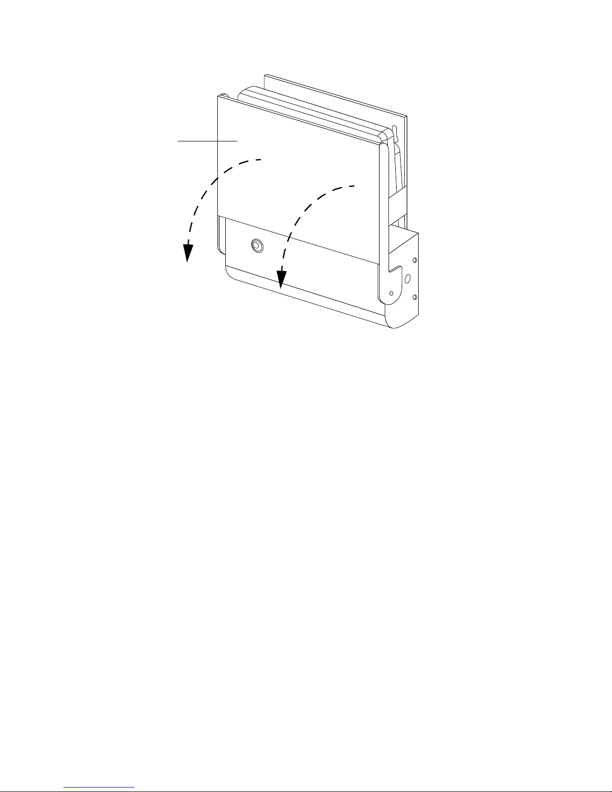
Keyboar d Tray
Figure 2-10. Opening the W all-Mount Cradle
Closing the Wall-Mount Cradle 2
You can close the wall-mount cradle at any time. The pen tablet does not have to be
removed to close the wall-mount cradle. It can be left in place to recharge the battery.
To close the wall-mount cradle, push the keyboard tray upward until it locks into the
vertical position. The keyboard tray is held in the closed position with magnetic
latches.
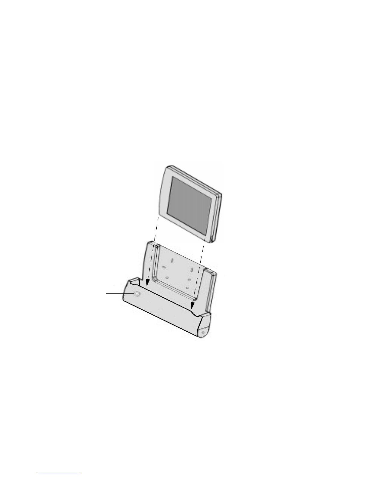
Inserting the P en Tab le t 2
To insert the pen tablet into the wall-mount cradle,
1. Suspend or shut down and turn off the pen tablet.
Note that driver software for the p eripheral device you intend to use with the
pen tablet system may need to be initialized upon starting the system. If this is
the case, you may need to shut down the system rather than suspend system
operation. Contact your local help desk or reseller for details on us ing specific
peripheral devices with your system.
2-24
Using Point 510/Point 1600 Connectivity Peripherals
Page 45
2. If using a locking-style wall- mount cradle, ensure that the cradle latches inside
the cradle are in the unlocked position. (See “S ynchronizing Cradle Latches” at
the end of this chapter for a description of how the cradle latches in the
high-connect ivity cradle work.)
3. Choose one of the following only if you have a locking version of the
wall-mount cradle. If you have a non-locking version, skip this step.
• If you intend to lock the pen tablet into the wall-mount cradle, ensure that
the tubular lock is in the unlocked position. See “Locking and Unlocking the
Wall-Mount Cradle” later in this chapter.
•If you do not intend to lock the pen tablet into the cradle, you can set the
tubular lock in the locked position if desired. This ensures that the cradle
latches stay in the unlocked position when you insert the pen tablet into the
cradle.
Figure 2-11. Inserting the Pen Tablet
Wall-Mount Cradle
2-25
Page 46

4. Choose one of the following:
• If you have a non-locking wall-mount cradle, or you do not intend to lock the
pen tablet into it, slide the pen tablet into the cradle. Note that the weight of
the pen tablet alone is sufficient to seat the connectors. It is not necessary to
force or push the pen tablet into the cradle (or engage the cradle latches) to
make the connection.
• If you have a locking wall-mount cradle and intend to lock the pen tablet
into it, you must push the pen tablet downwa rd into the cradle until the
cradle latches click into place. Do not rock the components as you push them
together. (See “Synchronizing Cradle Latches” at th e end of this chapter f or a
description of how the cradle latches in the wall-mount cradle work.)
5. If you are locking the pen tablet into the cradle, do so at this time. See “Locking
and Unlocking the Wall-Mount Cradle,” later in this chapter for details.
6. Start the pen tablet or, if you suspended the pen tablet, resume system
operation.
Locking and Unlocking the Wall-Mount Cradle 2
Note: Two versions of the wall-mount cradle are available: a locking version and a
non-locking version. This section is applicable only to the locking version.
The wall-mount cradle is equipped with a tubular lock that allows you to lock the
pen tablet into the cradle. You can also lock the cradle latches in the unlocked position.
This allows the pen tablet to be inserted i nto and removed from the cradle more
easily as the cradle latches do not engage the pen tablet.
To lock the pen tablet into the cradle,
1. Ensure that the pen tablet is properly inserted in the wall-mount cradle.
2. Insert the key into the tubular lock situated on the front of the cradle and turn
the key clockwise until it stops.
To unlock the pen tablet, insert the key into the tubular lock situated on the front of
the cradle and turn the key counter-clockwise until it stops.
2-26
Using Point 510/Point 1600 Connectivity Peripherals
Page 47

Removing th e Pen Tablet 2
To remove the pen tablet from the wall-mount cradle,
1. Suspend or shut down and turn off the pen tablet.
2. Choose one of the following:
• If the cradle latches are in the unlocked position, you can pull th e pen tablet
directly out of the cradle in a straight line.
• If the cradle latches are i n the locked position (the pen tablet cannot be
pulled directly out of the cradle), push the pen tablet into the cradle to
release the cradle latches. Note that if the tubular lock is in the locked
position, you also need to unlock the tubular lock before you can re lease the
cradle latches. Ensure that both cradle latches click into the unlocked
position. If the pen tablet remains locked inside the cradle or only one latch
releases, see “Synchronizing Cradle Latches” at the end of this chapter for a
description of the latch mechanism and techniques for removing the pen
tablet.
3. Once removed from the cradle, you can start the pen tablet or, if you suspended
the pen tablet, resume system operation.
Wall-Mount Cradle
2-27
Page 48

Charge-Onl y Crad le 2
The charge-only cradle is a desk-top Point 510 and Point 1600 connectivity peripheral
that connects the pen tablet to an AC adapter (only) for the purpose of recharging the
battery.
This section describes how to use the charge-only cradle. For information about
placing the AC adapter in the charge-only cradle, refer to the Connectivity Peripherals
Installation Guide: Point 510, Point 1600.
Inserting the P en Tab le t 2
The pen tablet does not have to be suspended or powered-down when it i s inserted
into or removed from the charge-only cradle.
To insert the pen tablet into the charge-only cradle,
1. Align the pen tablet with the cradle.
2. Slide the pen tablet into the cradle.
Note that the pen tablet just rests on the charge-only cradle. It does not click into
place.
Removing th e Pen Tablet 2
To remove the pen tablet from the charge-only cradle, lift the pen tablet up and out
of the cradle.
2-28
Using Point 510/Point 1600 Connectivity Peripherals
Page 49

Synchronizin g Cr adle Latche s 2
The port replicator, high-connectivity cradle , high-usage cradle, and wall-mount
cradle (collectively referred to here as the cradle) are available in locking and
non-locking versions. The locking versions are equipped with two “push-latch”
mechanisms (cradle latches) that hold the pen tablet in place when inserted. The
cradle latches (one on each side of the cradle) are activated when you push the pen
tablet into the cradle. When you insert the pen tablet into the cradle and push the pe n
tablet down, the cradle latches click into the locked position, holding the pen tablet
into the cradle. When you push the pen tablet down (into the cradle) a second time,
the cradle latches click into the unlocked position, allowing the pen tablet to be
removed from the cradle.
Notes: • The pen tablet ca n be inserted into and removed from the cradle without
engaging the cradle latches. To do so, ensure that the cradle latches are in the
unlocked position and insert or remove the pen tablet in to the cradle without
pushing the pen tablet do wn. (The weight of the pen tablet is sufficient to make
the connection between the cradle and t he pen tablet.)
• The tubular lock can be used to lock the cradle latches in either the locked or
unlocked position. If locking the pen tablet into the cradle is not required, you
can ensure that the cradle latch e s remain in the unlocked po sition by setting the
tubular lock in the locked posit ion.
Normally, you should be able to latch or unlatch the pen tablet without any concern,
however, since they operate independently, it is possible for the crad le latches to go
out of synchronization. That is, one latch can be in the locked position while the other
is in the unlocked position. When the cradle latches are out of synchronization, the
pen tablet cannot be inserted into (or removed from) the cradle. The following
discussion explains how to synchronize the cradle latches should they become
unsynchronized.
Synchronizing Cradle Latches
2-29
Page 50

Top View
Cradle LatchCradle Latch
Plate
Side View
Figure 2-12. Cradle Latches
Before inserting the pen tablet into the cradle, look inside the cradle and note the
position of the cradle latches. Both latches must be slanting inward, in the unlocked
position (See Figure 2-13). If one or both latches are in the upright (locked) position,
they must be set to the unlocked position before you can insert the pen tablet.
Locked position
Latch
Locked Position
Unlocked Position
Unlocked position
Figure 2-13. Checking Cr adle Latch Position
To synchronize the cradle latches, press the plate (shown in Figure 2-12) downward
with your hand on the side with the locked cradle latch until it clicks into the
unlocked position. (If both latches are in the locked position, press down on both
sides of the plate until they click into the unlocked position. Apply even pressure to
both sides.)
In the event the pen tablet is in the cradle, an d only one side locks or unlocks, press
down on one side of the pen tablet to synchronize the cradle latches.
Plate
2-30
Using Point 510/Point 1600 Connectivity Peripherals
Page 51

Chapter 3
Care and Maintenance of Connectivity Peripherals
This chapter describes how to handle and maintain connectivity peripherals.
Cautions 3
Please follow the guidelines in the caution box below when handling connectivity
peripherals.
Caution
Circuitry in the Point 510 and Point 1600 connectivity peripherals is designed to be
robust; however, the equipment can be damaged if procedures given in this chapter
are not followed r egarding the care and maintenance of connectivity peripherals. To
avoid damage to your hardware, observe the following guidelines:
• Disconnect the AC adapter power source to the peripheral prior to cleaning.
• Turn off all connected devices.
• Do not touch connec tor pins or conn ector soc k e ts on y our equipmen t. Elect rostati c
discharge can damage inte rface circuitry in your equipment.
• Do not place any part of a connectivity peripheral in water.
• Use only mild detergents and disinfectants on external portions of peripherals.
• Do not apply harsh cleaners directly to any part of a connectivity peripheral.
3-1
Page 52

Cleaning Con nect ivity Peripherals 3
The outside of the case, or shell, of connectivity peripherals may be cleaned. To clean
a cradle base and/or cradle module,
1. Slightly dampen a cloth or sponge with cleaner or disinfectant.
2. Wipe the outside of the connectivity peripheral case.
3. Do not apply cleaner to the inside of a cradle module.
It is recommended that you not clean the inside of a cradle module because it can
damage the connectors. In the event it is necessary to clean the inside of cradle
module,
1. Remove the pen tablet from the cradle module.
2. With a dry cotton cloth, gently rub the inside of the cradle module. Avoid
rubbing against connector pins.
3. If a more thorough cleaning is necessary, use cotton swabs to clean the inside of
a cradle module.
3-2
Care and Maintenance of Connectivity Peripherals
Page 53

Index
C
charge-only cradle
description
, 1-9
inserting the pen tablet
removing the pen tablet
using
, 2-28
connectivity peripherals
cleaning
, 3-2
handling precautions
part numbers
, vii
cradle latches
locked/unlocked p osition
locking
synchronizing
, 2-29
, 2-29
D
DC input
desk stand
, 2-6, 2-18
folding
setting up
, 2-13
, 2-11
viewing angles
, 2-11
, 2-28
, 2-1
, 2-28
, 2-30
inserting the pen tablet
locking
, 2-16
removing pen tablet
using
, 2-14
viewing angle, adjusting
high-us age cradle
description
, 1-4
inserting the pen tablet
locking
, 2-21
removing the pen tablet
viewing angle, adjusting
K
keyboard port
, 2-6, 2-18
M
maintenance
mouse port
, 3-1
, 2-2, 2-6, 2-18
P
, 2-14
, 2-18
, 2-17
, 2-19
, 2-22
, 2-21
F
floppy disk drive
connecting
to port replicator
to portable port expander
port
, 2-2, 2-6
folding desk stand
descripti on
, 2-13
, 1-10
H
handling precautions
high-con nectivity cradle
connectors
, 2-1, 3-1
, 2-14
, 2-6
, 1-6
, 2-2
parallel port
, 2-2, 2-6
port repli ca tor
attaching to desk stand
bottom view
descript ion
, 2-7
, 1-3
detaching desk stand
locking and unlocking
removing the pen tablet
portable port expander
attaching
connectors
descript ion
disconnecting
, 2-5
, 2-2
, 1-2
, 2-5
use with IrDA port
, 2-10
, 2-13
, 2-9
, 2-10
, 2-5
Index - 1
Page 54

R
related documentation
, viii
S
serial port A
serial port B
synchronizing cradle latches
system interface port
, 2-2, 2-6
, 2-2, 2-6
, 2-4, 2-5
T
tubular lock
, 2-9, 2-26, 2-29
V
video display, external
video port
, 2-2, 2-6
, 2-2, 2-6
W
, 2-29
wall-mount cradle
closed view
connectors
descripti on
, 2-24
, 2-23
, 1-8
inserting the pen tablet
keyboard tray
locking
, 2-26
opening and closing
removing the pen tablet
, 2-24
, 2-23
, 2-23
, 2-27
Index - 2
Page 55

Page 56

1/99 FMW26TRG5
58-0628-00A
 Loading...