

Page 1
Fujitsu Microelectronics Europe
User Guide
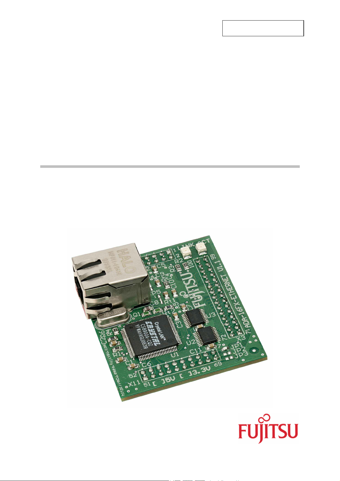
F²MC-16FX FAMILY
ADA-16FX-ETHERNET
FMEMCU-UG-960011-10
ADAPTER BOARD
USER GUIDE
Page 2

ADA-16FX-ETHERNET
Revision History
Revision History
Date Issue
11.01.2008 V1.0, TKi, First Release
This document contains 14 pages.
UG-960011-10 - 2 - © Fujitsu Microelectronics Europe GmbH
Page 3

ADA-16FX-ETHERNET
Warranty and Disclaimer
Warranty and Disclaimer
To the maximum extent permitted by applicable law, Fujitsu Microelectronics Europe GmbH restricts
its warranties and its liability for the ADA-16FX-ETHERNET Board and all its deliverables (eg.
software include or header files, application examples, target boards, evaluation boards, engineering
samples of IC’s etc.), its performance and any consequential damages, on the use of the Product in
accordance with (i) the terms of the License Agreement and the Sale and Purchase Agreement under
which agreements the Product has been delivered, (ii) the technical descriptions and (iii) all
accompanying written materials. In addition, to the maximum extent permitted by applicable law,
ujitsu Microelectronics Europe GmbH disclaims all warranties and liabilities for the performance of
F
the Product and any consequential damages in cases of unauthorised decompiling and/or reverse
engineering and/or disassembling. Note, the ADA-16FX-ETHERNET Board and all its deliverables
are intended and must only be used in an evaluation laboratory environment.
1. Fujitsu Microelectronics Europe GmbH warrants that the Product will perform substantially in
accordance with the accompanying written materials for a period of 90 days form the date of
receipt by the customer. Concerning the hardware components of the Product, Fujitsu
Microelectronics Europe GmbH warrants that the Product will be free from defects in material
and workmanship under use and service as specified in the accompanying written materials
for a duration of 1 year from the date of receipt by the customer.
2. Should a Product turn out to be defect, Fujitsu Microelectronics Europe GmbH´s entire liability
and the customer’s exclusive remedy shall be, at Fujitsu Microelectronics Europe GmbH´s
sole discretion, either return of the purchase price and the license fee, or replacement of the
Product or parts thereof, if the Product is returned to Fujitsu Microelectronics Europe GmbH in
original packing and without further defects resulting from the customer’s use or the transport.
However, this warranty is excluded if the defect has resulted from an accident not attributable
to Fujitsu Microelectronics Europe GmbH, or abuse or misapplication attributable to the
customer or any other third party not relating to Fujitsu Microelectronics Europe GmbH.
3. To the maximum extent permitted by applicable law Fujitsu Microelectronics Europe GmbH
disclaims all other warranties, whether expressed or implied, in particular, but not limited to,
warranties of merchantability and fitness for a particular purpose for which the Product is not
designated.
4. To the maximum extent permitted by applicable law, Fujitsu Microelectronics Europe GmbH´s
and its supplier’s liability are restricted to intention and gross negligence.
NO LIABILITY FOR CONSEQUENTIAL DAMAGES
To the maximum extent permitted by applicable law, in no event shall Fujitsu
Microelectronics Europe GmbH and its suppliers be liable for any damages whatsoever
(including but without limitation, consequential and/or indirect damages for personal
injury, assets of substantial value, loss of profits, interruption of business operation,
loss of information, or any other monetary or pecuniary loss) arising from the use of
the Product.
Should one of the above stipulations be or become invalid and/or unenforceable, the remaining
stipulations shall stay in full effect
© Fujitsu Microelectronics Europe GmbH - 3 - UG-960011-10
Page 4

ADA-16FX-ETHERNET
Chapter 1 Contents
1 Contents
REVISION HISTORY............................................................................................................ 2
WARRANTY AND DISCLAIMER ......................................................................................... 3
1 CONTENTS...................................................................................................................... 4
2 OVERVIEW...................................................................................................................... 5
2.1 Abstract................................................................................................................... 5
2.2 Features of adapter board ADA-16FX-ETHERNET v1.1 ......................................... 5
2.3 Features supported by base board SK-16FX-EUROSCOPE (SK-16FX-100PMC) .. 5
3 INSTALLATION ............................................................................................................... 6
3.1 Jumper settings of ADA-16FX-ETHERNET v1.1 ..................................................... 7
4 JUMPERS AND LED’S.................................................................................................... 8
4.1 Chip select (JP: 1, 2, 3) ........................................................................................... 8
4.2 Ethernet jack Select (JP: 4, 5) ................................................................................. 8
4.3 Link LED, Activity LED (LINK, ACT) ........................................................................ 9
5 CONNECTORS.............................................................................................................. 10
5.1 Ethernet connector (X1) ........................................................................................ 10
5.2 Edge Connectors (X2, X3, X11) ............................................................................ 10
6 SILK-PLOT OF THE BOARD ........................................................................................ 11
7 RELATED PRODUCTS ................................................................................................. 12
8 INFORMATION IN THE WWW....................................................................................... 13
UG-960011-10 - 4 - © Fujitsu Microelectronics Europe GmbH
Page 5

ADA-16FX-ETHERNET
Chapter 2 Overview
2 Overview
2.1 Abstract
The ADA-16FX-ETHERNET is an adapter board that can be used together with the
evaluation board SK-16FX-EUROSCOPE (SK-16FX-100PMC). The ADA-16FX-ETHERNET
extends the evaluation board with Ethernet connectivity. It can be used for software
development and testing.
The board allows the designer immediately to start with the software development before a
final target system is available.
2.2 Features of adapter board ADA-16FX-ETHERNET
< 10BaseT Ethernet connectivity
< Software example including openTCP stack is available
< Multiplexed bus interface
< Selectable chip select via Jumper
< Pin header for SK-16FX-EUROSCOPE (SK-16FX-100PMC) base board
(Note: SK-16FX-EUROSCOPE has to be ordered separately)
2.3 Features of base board SK-16FX-EUROSCOPE (SK-16FX-100PMC)
< 1x UART-Transceiver (SUB-D9 connector)
< 1x USB to serial converter (Type-B connector)
< 1x High-speed CAN-Transceiver (SUB-D9 connector)
< 2x LED-Display (7-Segment)
< 2x User-button
< 1x Reset-button, Reset-LED
< All 100 pins routed to pin-header
< On-board 5V and 3V voltage regulators, Power-LED
< USB power-supply (external power supply possible)
This board must only be used for test applications
in an evaluation laboratory environment.
© Fujitsu Microelectronics Europe GmbH - 5 - UG-960011-10
Page 6

ADA-16FX-ETHERNET
Chapter 3 Installation
3 Installation
Remove carefully the board from the shipping box and check for any damages.
Disconnect your SK-16FX-EUROSCOPE (SK-16FX-100PMC) evaluation board from USB
and external power supply. Select the correct Voltage supply:
ADA-16FX-ETHERNET is designed for 5V power supply.
Jumper Setting Description
JP10 (5V/3V3)
1-2 VCC is set to 5V (ADA-16FX-ETHERNET)
2-3 VCC is set to 3.3V
Attach the adapter board to the evaluation board as shown below. The Ethernet jack has to
face to the outer edge.
Ethernet jack
Note:
Make sure to jumper the board to 5V before connecting the ADA-16FX-ETHERNET.
UG-960011-10 - 6 - © Fujitsu Microelectronics Europe GmbH
Page 7

ADA-16FX-ETHERNET
Chapter 3 Installation
3.1 Jumper settings of ADA-16FX-ETHERNET
The following jumper settings are set by default:
Jumper Description / Function Type Default
JP1 Use chip select line 2 solder JP 2pol. Closed
JP2 Use chip select line 3 solder JP 2pol. Open
JP3 Use chip select line 4 solder JP 2pol. Open
JP4 Select center tap A of Ethernet jack solder JP 3pol. 1-2
JP5 Select center tap B of Ethernet jack solder JP 3pol. 1-2
Please refer to the documentation of the evaluation board for detailed information about the
jumper settings for the SK-16FX-EUROSCOPE (SK-16FX-100PMC).
© Fujitsu Microelectronics Europe GmbH - 7 - UG-960011-10
Page 8

ADA-16FX-ETHERNET
Chapter 4 Jumpers and LED’s
4 Jumpers and LED’s
This chapter describes all jumpers that can be modified and all LED’s on the adapter board.
The default setting is shown with a grey shaded area.
4.1 Chip select (JP: 1, 2, 3)
One out of the three chip select signals CS2, CS3 or CS4 can be selected:
JP1, JP2, JP3 connect chip select signal of MCU to chip select signal of Ethernet chip
Jumper Setting Description
ON (closed) CS2 is connected to CHIPSEL of CS8900A
JP1 (CS2)
OFF (open) CS2 is not connected
ON (closed) CS3 is connected to CHIPSEL of CS8900A
JP2 (CS3)
OFF (open) CS3 is not connected
ON (closed) CS4 is connected to CHIPSEL of CS8900A
JP3 (CS4)
OFF (open) CS4 is not connected
Default: JP1 is closed
By default, the chip select signal CS2 of the MB96F348HS is connected to the Ethernet chip.
4.2 Ethernet jack select (JP: 4, 5)
The board layout is designed to be used with different Ethernet jacks.
JP4, JP5 Select center tap pin of Ethernet jack
Jumper Setting Description
1-2 Capacitor 9 is connected to pin 4 of the
Ethernet jack
JP4 (AVss)
2-3 Capacitor 9 is connected to pin 7 of the
Ethernet jack
1-2 Capacitor 10 is connected to pin 5 of the
Ethernet jack
JP5 (AVcc)
2-3 Capacitor 10 is connected to pin 8 of the
Ethernet jack
Default: JP4 and JP5 are set to 1-2
By default the pins 4 and 5 of the assembled Ethernet jack are used as center tap pin. This
setting depends on the type and manufacturer of the used Ethernet jack (see chapter 5.1).
UG-960011-10 - 8 - © Fujitsu Microelectronics Europe GmbH
Page 9

ADA-16FX-ETHERNET
Chapter 4 Jumpers and LED’s
4.3 Link LED, Activity LED (LINK, ACT)
These LEDs display the status of the Ethernet interface.
LED Colour Description
LINK Green Indicates that a link is established
ACT Yellow Indicates activity on the Ethernet
By default the LINK LED should light directly after connected to a network.
© Fujitsu Microelectronics Europe GmbH - 9 - UG-960011-10
Page 10

ADA-16FX-ETHERNET
Chapter 5 Connectors
5 Connectors
5.1 Ethernet connector (X1)
This is the Ethernet jack for connecting the ADA-16FX-ETHERNET to the Ethernet. The
connector complies with the 10BaseT standard. The used connector has integrated
transformers for transmit and receive lines.
The Ethernet jack and the Ethernet controller depends on the power supply voltage:
Supply Voltage Used jack Ethernet Chip Adapter Board
5V
3V3
Halo HFJ11-
1043E
Halo HFJ11-
1041E
CS8900CQZ
CS8900CQ3Z - 1:1 1:2.5
ADA-16FX-
ETHERNET
Rx
Transitions
1:1 1:1.41
Transitions
5.2 Edge Connectors (X2, X3, X11)
The edge connectors are assembled on the bottom side of the adapter board. They are used
to attach the ADA-16FX-ETHERNET adapter board to the SK-16FX-EUROSCOPE (SK16FX-100PMC) evaluation board. All used signals are provided by the edge connectors.
Connector MCU Pins
X2 (1 – 20) 1 – 20
X3 (71 – 100) 71 – 100
X11 (51 – 70) 51 – 70
Tx
The adapter board is powered via the edge connectors.
UG-960011-10 - 10 - © Fujitsu Microelectronics Europe GmbH
Page 11

Chapter 6 Silk-Plot of the Board
X
2
X3
X11
Latch
Latch
6 Silk-Plot of the Board
Ethernet
connector
X1
ADA-16FX-ETHERNET
Cirrus
CS8900A
© Fujitsu Microelectronics Europe GmbH - 11 - UG-960011-10
Page 12

ADA-16FX-ETHERNET
Chapter 7 Related Products
7 Related Products
< SK-16FX-EUROSCOPE Evaluation board with MB96F348HS
FPT-100P-M20 package
< ADA-16FX-ETHERNET Adapterboard for SK-16FX-EUROSCOPE
(SK-16FX-100PMC)
< MB96F348HS MB96340 Series Flash MCU
UG-960011-10 - 12 - © Fujitsu Microelectronics Europe GmbH
Page 13

ADA-16FX-ETHERNET
Chapter 8 Information in the WWW
8 Information in the WWW
Information about FUJITSU MICROELECTRONICS Products
can be found on the following Internet pages:
Microcontrollers (8-, 16-, and 32bit), Graphics Controllers
Datasheets and Hardware Manuals, Support Tools (Hard- and Software)
http://mcu.emea.fujitsu.com
Linear Products: Power Management, A/D and D/A Converters
http://www.fujitsu.com/emea/services/microelectronics/linears/
Media Products: SAW filters, acoustic resonators and VCOs
http://www.fujitsu.com/emea/services/microelectronics/saw/
For more information about FUJITSU MICROELECTRONICS
http://www.fujitsu.com/emea/services/microelectronics/
© Fujitsu Microelectronics Europe GmbH - 13 - UG-960011-10
Page 14

ADA-16FX-ETHERNET
Chapter 8 Information in the WWW
Recycling
Gültig für EU-Länder:
Gemäß der Europäischen WEEE-Richtlinie und deren Umsetzung in landesspezifische
Gesetze nehmen wir dieses Gerät wieder zurück.
Zur Entsorgung schicken Sie das Gerät bitte an die folgende Adresse:
Fujitsu Microelectronics Europe GmbH
Warehouse/Disposal
Monzastraße 4a
63225 Langen
Valid for European Union Countries:
According to the European WEEE-Directive and its implementation into national laws we
take this device back.
For disposal please send the device to the following address:
Fujitsu Microelectronics Europe GmbH
Warehouse/Disposal
Monzastraße 4a
D-63225 Langen
Germany
UG-960011-10 - 14 - © Fujitsu Microelectronics Europe GmbH
 Loading...