

Page 1

ETERNUS DX80 S2/DX90 S2
Disk storage system
User's Guide -Operation-
P3AM-4842-12ENZ0
Page 2

This page is intentionally left blank.
Page 3

Preface
Fujitsu would like to thank you for purchasing our ETERNUS DX80 S2/DX90 S2 Disk storage system.
The ETERNUS DX80 S2/DX90 S2 Disk storage system is designed to be connected to a Fujitsu (PRIMEQUEST or
PRIMERGY) or non-Fujitsu servers.
This manual describes operation management and maintenance for the ETERNUS DX80 S2/DX90 S2 Disk
storage system.
This manual is intended for use of ETERNUS DX Disk storage system in regions other than Japan.
Please carefully review the information outlined in this manual.
Twelfth Edition
June 2013
Windows is a registered trademark of Microsoft Corporation in the United States and/or other countries.
IBM, AIX, and Tivoli are trademarks of International Business Machines Corporation, registered in many
jurisdictions worldwide.
The company names, product names and service names mentioned in this document are registered
trademarks or trademarks of their respective companies.
Microsoft product screen shot(s) reprinted with permission from Microsoft Corporation.
3
ETERNUS DX80 S2/DX90 S2 Disk storage system User’s Guide -Operation-
Copyright 2013 FUJITSU LIMITED P3AM-4842-12ENZ0
Page 4

Organization
This document is composed of the following seven chapters and three appendices:
● Chapter 1 Components
This chapter describes the components of the ETERNUS DX80 S2/DX90 S2 Disk storage system.
● Chapter 2 Basic Operation
This chapter explains how to turn on and off the ETERNUS DX80 S2/DX90 S2 Disk storage system and how
to operate the FUNCTION button on the controller enclosure.
● Chapter 3 Setup
This chapter describes the required settings for operation of the ETERNUS DX80 S2/DX90 S2 Disk storage
system and provides notes for setting up each function of the ETERNUS DX80 S2/DX90 S2 Disk storage
system.
About this Manual
● Chapter 4 Operations
This chapter describes the control of the LAN for operation management of the ETERNUS DX80 S2/DX90 S2
Disk storage system, and the monitoring the status of the ETERNUS DX80 S2/DX90 S2 Disk storage system.
● Chapter 5 Maintaining Optional Products
This chapter explains how to install optional products in the ETERNUS DX80 S2/DX90 S2 Disk storage
system.
● Chapter 6 Maintenance
This chapter describes maintenance for the ETERNUS DX80 S2/DX90 S2 Disk storage system.
● Chapter 7 Troubleshooting
This chapter explains troubleshooting when errors occur in the ETERNUS DX80 S2/DX90 S2 Disk storage
system.
"Event Notification Message List"
Operation Manager" are described as appendices.
, "Audit Log List", and "Event (SNMP Trap) Display When Using ServerView
4
ETERNUS DX80 S2/DX90 S2 Disk storage system User’s Guide -Operation-
Copyright 2013 FUJITSU LIMITED P3AM-4842-12ENZ0
Page 5
About this Manual
WARNING
CAUTION
Electric Shock
No Disassembly
Unplug
Warning Notations
Warning signs are shown throughout this manual in order to prevent injury to the user and/or material
damage. These signs are composed of a symbol and a message describing the recommended level of caution.
The following section explains the symbols, their levels of caution, and their meanings as used in this manual.
This symbol indicates the possibility of serious or fatal injury if the ETERNUS
DX80 S2/DX90 S2 Disk storage system is not used properly.
This symbol indicates the possibility of minor or moderate personal injury, as
well as damage to the ETERNUS DX Disk storage system and/or to other users
and their property, if the ETERNUS DX80 S2/DX90 S2 Disk storage system is not
used properly.
This symbol indicates IMPORTANT information for the user to note when using
the ETERNUS DX80 S2/DX90 S2 Disk storage system.
The following symbols are used to indicate the type of warnings or cautions being described.
The triangle emphasizes the urgency of the WARNING and CAUTION
contents. Inside the triangle and above it are details concerning the symbol
(e.g. Electrical Shock).
The barred "Do Not..." circle warns against certain actions. The action
which must be avoided is both illustrated inside the barred circle and written
above it (e.g. No Disassembly).
The black "Must Do..." circle indicates actions that must be taken. The
required action is both illustrated inside the black disk and written above it
(e.g. Unplug).
5
ETERNUS DX80 S2/DX90 S2 Disk storage system User’s Guide -Operation-
Copyright 2013 FUJITSU LIMITED P3AM-4842-12ENZ0
Page 6

About this Manual
Warning Level Indicator
Warning Type Indicator
Warning Details
To avoid damaging the ETERNUS DX80 S2/DX90 S2
Disk storage system, pay attention to the following points when cleaning
the ETERNUS DX80 S2/DX90 S2 Disk storage system:
- Make sure to disconnect the power when cleaning.
- Be careful that no liquid seeps into the ETERNUS DX80 S2/DX90 S2
Disk storage system when using cleaners, etc.
- Do not use alcohol or other solvents to clean
the ETERNUS DX80 S2/DX90 S2 Disk storage system.
Warning Layout Ribbon
Example Warning
How Warnings are Presented in this Manual
A message is written beside the symbol indicating the caution level. This message is marked with a vertical
ribbon in the left margin, to distinguish this warning from ordinary descriptions.
An example is shown here.
Additional Information
Symbols Used in This Manual
Abbreviations Used in This Manual
The following is a symbol used throughout this manual:
Functions and know how which can be useful when setting up or operating the
ETERNUS DX80 S2/DX90 S2 Disk storage system.
• "ETERNUS DX Disk storage system" refers to the DX80 S2/DX90 S2 Disk storage system.
• "CA" refers to a host interface module that is used in an ETERNUS DX Disk storage system to connect to a
server.
• "Host Bus Adapter (HBA)" refers to the interface module that is normally used by the server to connect to
ETERNUS DX Disk storage systems.
An "FC card", "LAN card", "Network Interface Card (NIC)", "Converged Network Adapter (CNA)", or "SAS card"
may be used instead, depending on the server and interface.
• Trademark symbols such as ™ and ® are omitted in this document.
ETERNUS DX80 S2/DX90 S2 Disk storage system User’s Guide -Operation-
Copyright 2013 FUJITSU LIMITED P3AM-4842-12ENZ0
6
Page 7

Table of Contents
Chapter 1 Components 12
1.1 Controller Enclosure .......................................................................................................... 12
1.1.1 Front ..............................................................................................................................................................12
1.1.2 Rear ............................................................................................................................................................... 13
1.1.3 Components (Front) ......................................................................................................................................14
1.1.4 Components (Rear) .......................................................................................................................................17
1.2 Drive Enclosures ................................................................................................................ 23
1.2.1 Front ..............................................................................................................................................................23
1.2.2 Rear ............................................................................................................................................................... 24
1.2.3 Components (Front) ......................................................................................................................................24
1.2.4 Components (Rear) .......................................................................................................................................27
1.3 Power Distribution Units (for Regions other than EMEA&I) ............................................... 29
1.3.1 Power Distribution Units (1U) ........................................................................................................................ 29
1.3.2 Power Distribution Units (2U) ........................................................................................................................ 30
Chapter 2 Basic Operation 32
2.1 Powering On and Off .........................................................................................................32
2.1.1 Switching On and Off the Main Line Switch on the Power Distribution Unit
(for Regions Other than EMEA&I) ..................................................................................................................32
2.1.2 Switching On and Off the PSU Switch on the Power Supply Unit .................................................................... 35
2.1.3 Powering On .................................................................................................................................................. 36
2.1.4 Powering Off ..................................................................................................................................................38
2.2 Using the FUNCTION Button .............................................................................................. 39
Chapter 3 Setup 41
3.1 Thin Provisioning Setup .................................................................................................... 41
3.1.1 Registering the Thin Provisioning Feature License ........................................................................................41
3.1.2 Thin Provisioning Setup ................................................................................................................................. 42
3.1.3 Restrictions and Notes When Using the Thin Provisioning Function ..............................................................42
3.2 Flexible Tier (Auto Storage Layering) Setup ...................................................................... 44
3.2.1 Registering the Thin Provisioning Feature License ........................................................................................44
3.2.2 Flexible Tier Setup ......................................................................................................................................... 45
3.2.3 Restrictions and Notes ................................................................................................................................... 45
3.3 Storage Migration ............................................................................................................. 47
7
ETERNUS DX80 S2/DX90 S2 Disk storage system User’s Guide -Operation-
Copyright 2013 FUJITSU LIMITED P3AM-4842-12ENZ0
Page 8

Table of Contents
3.4 Data Encryption ................................................................................................................ 48
3.5 Key Management Server Linkage ...................................................................................... 50
3.6 Eco-mode .......................................................................................................................... 51
3.7 Optimizing Volume Configurations ...................................................................................53
3.7.1 RAID Migration .............................................................................................................................................. 54
3.7.2 Logical Device Expansion (LDE) ..................................................................................................................... 55
3.7.3 LUN Concatenation ........................................................................................................................................ 56
3.7.4 Wide Striping ................................................................................................................................................. 57
Chapter 4 Operations 58
4.1 LAN for Operation Management ....................................................................................... 58
4.2 Monitoring ETERNUS DX Disk Storage System Status ........................................................60
4.2.1 LED Status Check ...........................................................................................................................................60
4.2.2 Displaying Status via ETERNUS Web GUI ........................................................................................................61
4.2.3 Event Notification ..........................................................................................................................................62
4.2.4 Audit Log ....................................................................................................................................................... 63
Chapter 5 Maintaining Optional Products 64
5.1 Installing Drives ................................................................................................................ 64
5.1.1 Installation Rules for Drives ........................................................................................................................... 65
5.1.2 Installable Drives ........................................................................................................................................... 65
5.1.3 Drive Handling Instructions ........................................................................................................................... 66
5.1.4 Additional Drive Installation Procedure .........................................................................................................67
5.2 Installing Drive Enclosures ................................................................................................ 72
5.2.1 Installation Rules for Drive Enclosures ........................................................................................................... 72
5.2.2 Installable Drive Enclosures ........................................................................................................................... 72
5.2.3 Drive Enclosure Handling Instructions ........................................................................................................... 72
5.2.4 Additional Drive Enclosure Installation .......................................................................................................... 73
5.3 Installing Host Interfaces ..................................................................................................85
5.3.1 Installation Rules for Host Interfaces .............................................................................................................85
5.3.2 Installable Host Interfaces .............................................................................................................................86
5.3.3 Host Interface Handling Instructions .............................................................................................................86
5.4 Installing Long Wave SFP+ Modules (16Gbit/s) ................................................................. 87
5.4.1 Installation Rules for Long Wave SFP+ Modules (16Gbit/s) ............................................................................ 87
5.4.2 Installable Long Wave SFP+ Modules (16Gbit/s) ............................................................................................ 88
5.4.3 SFP+ Module Handling Instructions ...............................................................................................................88
5.4.4 Long Wave SFP+ Modules (16Gbit/s) Installation Procedure ..........................................................................89
8
ETERNUS DX80 S2/DX90 S2 Disk storage system User’s Guide -Operation-
Copyright 2013 FUJITSU LIMITED P3AM-4842-12ENZ0
Page 9

Table of Contents
Chapter 6 Maintenance 93
6.1 Periodic Backup ................................................................................................................93
6.2 Volume Formatting Time .................................................................................................. 93
6.3 Rebuild/Copyback Process Time ........................................................................................94
6.4 Maintenance Service .........................................................................................................95
6.4.1 Maintenance Support Period .........................................................................................................................95
6.4.2 Related Service ..............................................................................................................................................95
Chapter 7 Troubleshooting 96
7.1 Check List .......................................................................................................................... 96
7.2 Required Information for Inquiries ..................................................................................102
Appendix A Event Notification Message List 103
A.1 Message Format .............................................................................................................. 103
A.1.1 E-mail.......................................................................................................................................................... 103
A.1.2 Syslog.......................................................................................................................................................... 105
A.1.3 SNMP........................................................................................................................................................... 107
A.1.4 Host Sense................................................................................................................................................... 111
A.2 Message List.................................................................................................................... 112
A.2.1 Common Terms............................................................................................................................................ 112
A.2.2 Error Messages ............................................................................................................................................ 113
A.2.3 Warning Messages ...................................................................................................................................... 133
A.2.4 Informational Messages.............................................................................................................................. 143
A.2.5 Test Messages ............................................................................................................................................. 149
A.2.6 Sense Codes................................................................................................................................................. 149
Appendix B Audit Log List 154
Appendix C Event (SNMP Trap) Display When Using
ServerView Operation Manager 183
9
ETERNUS DX80 S2/DX90 S2 Disk storage system User’s Guide -Operation-
Copyright 2013 FUJITSU LIMITED P3AM-4842-12ENZ0
Page 10

List of Figures
Figure 1.1 Front view of a 2.5" type controller enclosure.............................................................................................. 12
Figure 1.2 Front view of a 3.5" type controller enclosure.............................................................................................. 12
Figure 1.3 Rear view of a controller enclosure (single-controller type) ........................................................................ 13
Figure 1.4 Rear view of a controller enclosure (dual-controller type)........................................................................... 13
Figure 1.5 Operation panel (2.5" type controller enclosure)......................................................................................... 14
Figure 1.6 Operation panel (3.5" type controller enclosure)......................................................................................... 14
Figure 1.7 2.5" drive..................................................................................................................................................... 16
Figure 1.8 Drive slot numbers (2.5" type controller enclosure)..................................................................................... 16
Figure 1.9 3.5" drive..................................................................................................................................................... 16
Figure 1.10 Drive slot numbers (3.5" type controller enclosure)..................................................................................... 16
Figure 1.11 Controller .................................................................................................................................................... 17
Figure 1.12 Host interface (FC, iSCSI 10Gbit/s, FCoE (for FC cable connection)).............................................................. 19
Figure 1.13 Host interface (iSCSI 10Gbit/s, FCoE (for Copper Twinax cable connection)) ................................................ 20
Figure 1.14 Host interface (iSCSI 1Gbit/s)....................................................................................................................... 20
Figure 1.15 Host interface (SAS) .................................................................................................................................... 21
Figure 1.16 Power supply unit........................................................................................................................................ 21
Figure 1.17 Front view of a 2.5" type drive enclosure ..................................................................................................... 23
Figure 1.18 Front view of a 3.5" type drive enclosure ..................................................................................................... 23
Figure 1.19 Rear view of a drive enclosure (single-IOM type) ........................................................................................ 24
Figure 1.20 Rear view of a drive enclosure (dual-IOM type)........................................................................................... 24
Figure 1.21 LEDs on the front side of the drive enclosure .............................................................................................. 25
Figure 1.22 2.5" drive..................................................................................................................................................... 25
Figure 1.23 Drive slot numbers (2.5" type drive enclosure)............................................................................................ 26
Figure 1.24 3.5" drive..................................................................................................................................................... 26
Figure 1.25 Drive slot numbers (3.5" type drive enclosure)............................................................................................ 26
Figure 1.26 I/O module .................................................................................................................................................. 27
Figure 1.27 Power supply unit........................................................................................................................................ 28
Figure 1.28 Power distribution unit for DX80 S2/DX90 S2 (AC200-240V, 1U, Max 2 enclosures connection).................. 29
Figure 1.29 Power distribution unit for DX80 S2/DX90 S2 (AC200-240V, 2U, Max 6 enclosures connection).................. 30
Figure 1.30 Power distribution unit for DX80 S2/DX90 S2 (AC200-240V, 2U, Max 8 enclosures connection).................. 31
Figure 2.1 ON position (marked "|") of the main line switches on a 1U power distribution unit................................... 32
Figure 2.2 ON position (marked "|") of the main line switches on a 2U power distribution unit................................... 33
Figure 2.3 OFF position (marked "O") of the main line switches on a 1U power distribution unit................................. 33
Figure 2.4 OFF position (marked "O") of the main line switches on a 2U power distribution unit................................. 34
Figure 2.5 ON position (marked "|") of the PSU switch on a power supply unit ............................................................ 35
Figure 2.6 OFF position (marked "O") of the PSU switch on a power supply unit .......................................................... 36
Figure 3.1 System configuration for linking with the key management server............................................................. 50
Figure 4.1 LAN control (switching of the Master CM) ................................................................................................... 59
Figure 4.2 LAN control (when the IP address of the Slave CM is set) ............................................................................ 59
Figure 4.3 ETERNUS Web GUI screen ............................................................................................................................ 61
Figure 4.4 Event notification........................................................................................................................................ 63
Figure 4.5 Audit logs .................................................................................................................................................... 63
Figure 5.1 Positions of 2.5" drive slots.......................................................................................................................... 65
Figure 5.2 Positions of 3.5" drive slots.......................................................................................................................... 65
Figure 5.3 Installation diagram for a host interface (single-controller type)................................................................ 85
Figure 5.4 Installation diagram for host interfaces (dual-controller type).................................................................... 86
10
ETERNUS DX80 S2/DX90 S2 Disk storage system User’s Guide -Operation-
Copyright 2013 FUJITSU LIMITED P3AM-4842-12ENZ0
Page 11

List of Tables
Table 1.1 Status and meanings of each LED (operation panel (controller enclosure))................................................ 15
Table 1.2 Status and meanings of each LED (drive).................................................................................................... 17
Table 1.3 Status and meanings of each LED (controller) ............................................................................................ 18
Table 1.4 Status and meanings of each LED (power supply unit) ............................................................................... 22
Table 1.5 Status and meanings of each LED (in front of drive enclosure) ................................................................... 25
Table 1.6 Status and meanings of each LED (drive).................................................................................................... 26
Table 1.7 Status and meanings of each LED (I/O module) .......................................................................................... 27
Table 1.8 Status and meanings of each LED (power supply unit) ............................................................................... 28
Table 4.1 General status of ETERNUS Web GUI ............................................................................................................ 61
Table 6.1 Time for volume formatting (disk) .............................................................................................................. 93
Table 6.2 Rebuild process time (disk)......................................................................................................................... 94
Table 6.3 Copyback process time (disk) ...................................................................................................................... 94
11
ETERNUS DX80 S2/DX90 S2 Disk storage system User’s Guide -Operation-
Copyright 2013 FUJITSU LIMITED P3AM-4842-12ENZ0
Page 12
Chapter 1
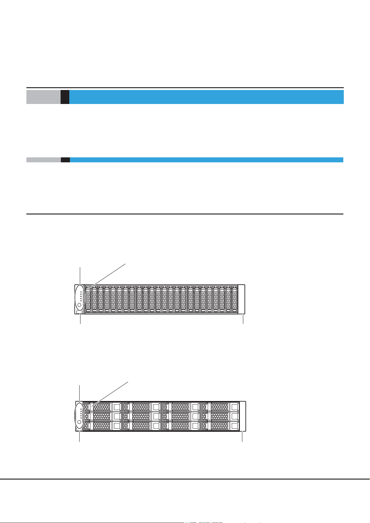
Operation panel
2.5" disk or 2.5" Solid State Drive (SSD)
Flange cover Flange cover
Operation panel
Flange cover Flange cover
3.5" disk or 3.5" Solid State Drive (SSD)
Components
This chapter describes the components of the ETERNUS DX Disk storage system.
1.1 Controller Enclosure
An operation panel and drives are installed in the front of the controller enclosure. Controllers and power
supply units are installed in the rear.
1.1.1 Front
■ 2.5" type
Figure 1.1 Front view of a 2.5" type controller enclosure
■ 3.5" type
Figure 1.2 Front view of a 3.5" type controller enclosure
12
ETERNUS DX80 S2/DX90 S2 Disk storage system User’s Guide -Operation-
Copyright 2013 FUJITSU LIMITED P3AM-4842-12ENZ0
Page 13
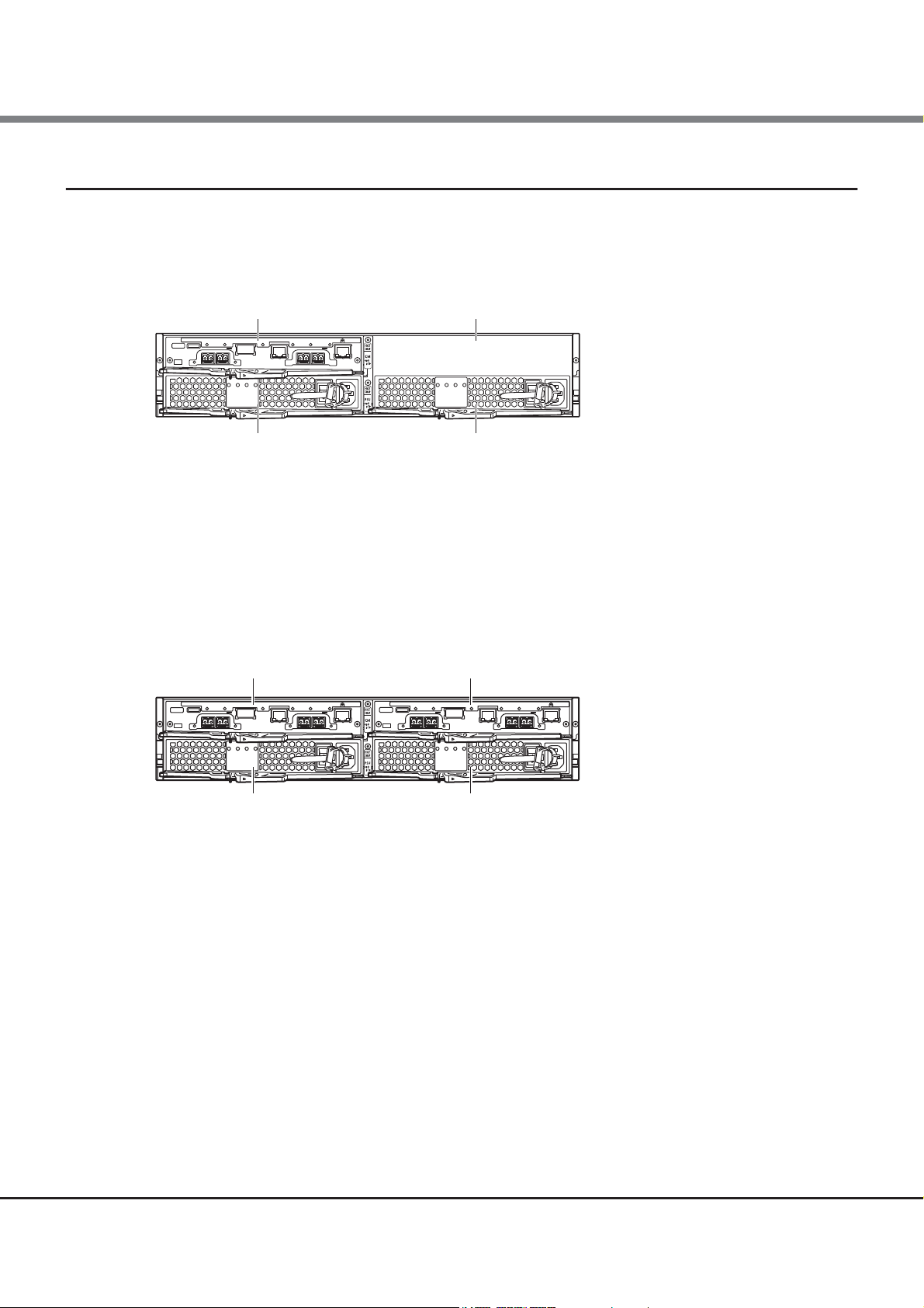
Chapter 1 Components
Power supply unit (PSU#0) Power supply unit (PSU#1)
Controller (CM#0) Cover
Power supply unit (PSU#0) Power supply unit (PSU#1)
Controller (CM#0) Controller (CM#1)
1.1 Controller Enclosure
1.1.2 Rear
■ Single-controller type
Figure 1.3 Rear view of a controller enclosure (single-controller type)
● Part explanation
• Cover
Remove this when installing an additional controller (optional).
■ Dual-controller type
Figure 1.4 Rear view of a controller enclosure (dual-controller type)
ETERNUS DX80 S2/DX90 S2 Disk storage system User’s Guide -Operation-
13
Copyright 2013 FUJITSU LIMITED P3AM-4842-12ENZ0
Page 14
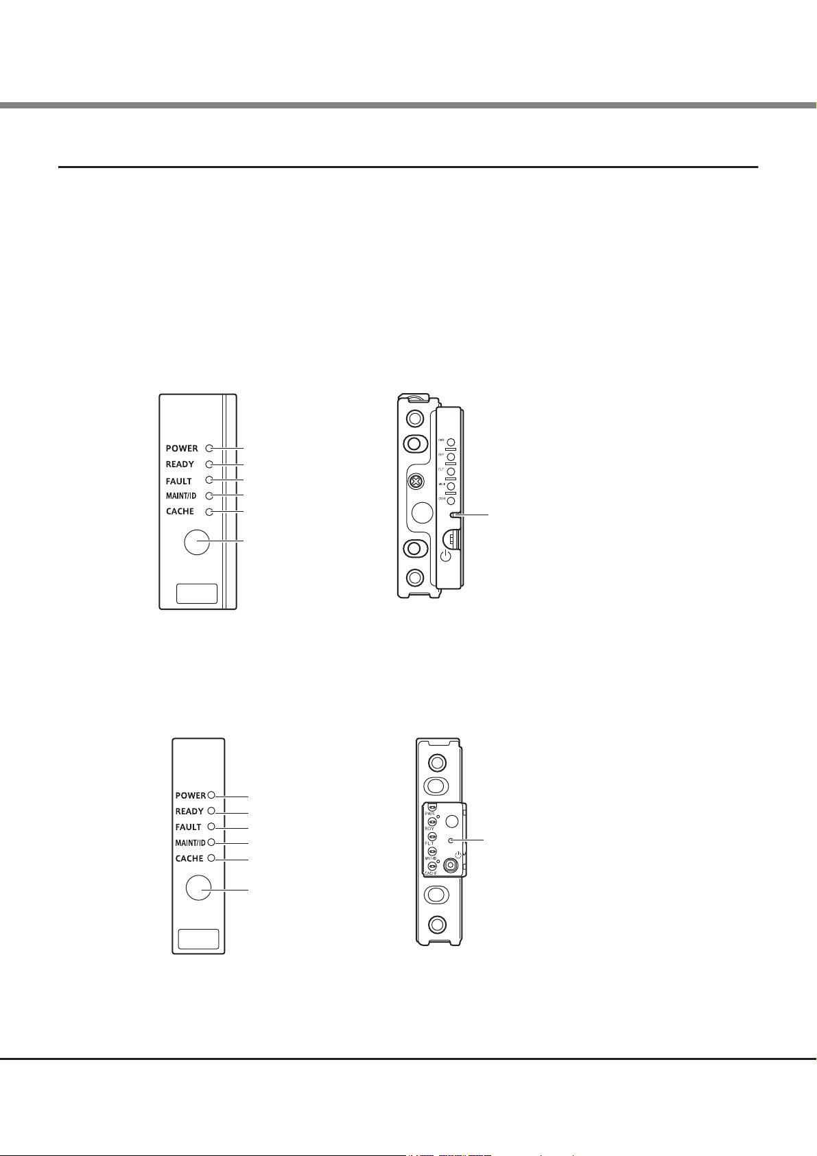
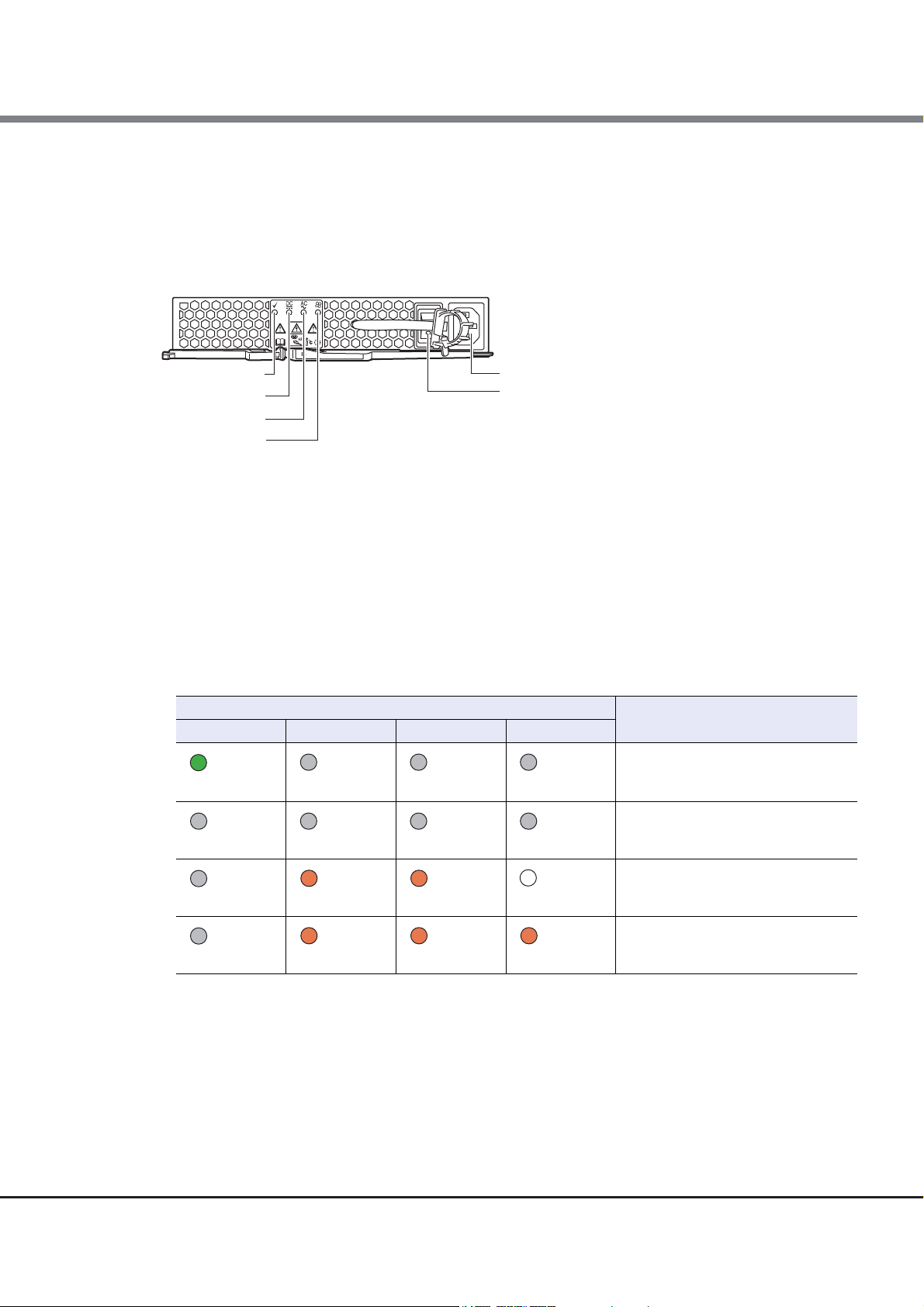
Chapter 1 Components
With a flange cover
CACHE LED
MAINT/ID LED
FAULT LED
READY LED
Power switch
POWER LED
Without a flange cover
FUNCTION button
With a flange cover
Power switch
CACHE LED
MAINT/ID LED
FAULT LED
READY LED
POWER LED
Without a flange cover
FUNCTION button
1.1 Controller Enclosure
1.1.3 Components (Front)
This section describes the operation panel and the drives in the front of the controller enclosure.
■ Operation panel
An operation panel has LEDs, a Power switch, and a FUNCTION button.
● 2.5" type
Figure 1.5 Operation panel (2.5" type controller enclosure)
● 3.5" type
Figure 1.6 Operation panel (3.5" type controller enclosure)
14
ETERNUS DX80 S2/DX90 S2 Disk storage system User’s Guide -Operation-
Copyright 2013 FUJITSU LIMITED P3AM-4842-12ENZ0
Page 15

Chapter 1 Components
1.1 Controller Enclosure
● Part explanation
• Power switch
This switch is used to turn on or off the ETERNUS DX Disk storage system.
• FUNCTION button
Hold down the button for three seconds during maintenance to stop the maintenance operation. Hold
down the button for three seconds while a maintenance operation is not performed to start the
maintenance operation.
For a dual-controller type, press the button twice within three seconds during maintenance to switch the
Master CM to the other controller.
Press the button three times within three seconds during maintenance to restore the factory default
settings of the LAN ports.
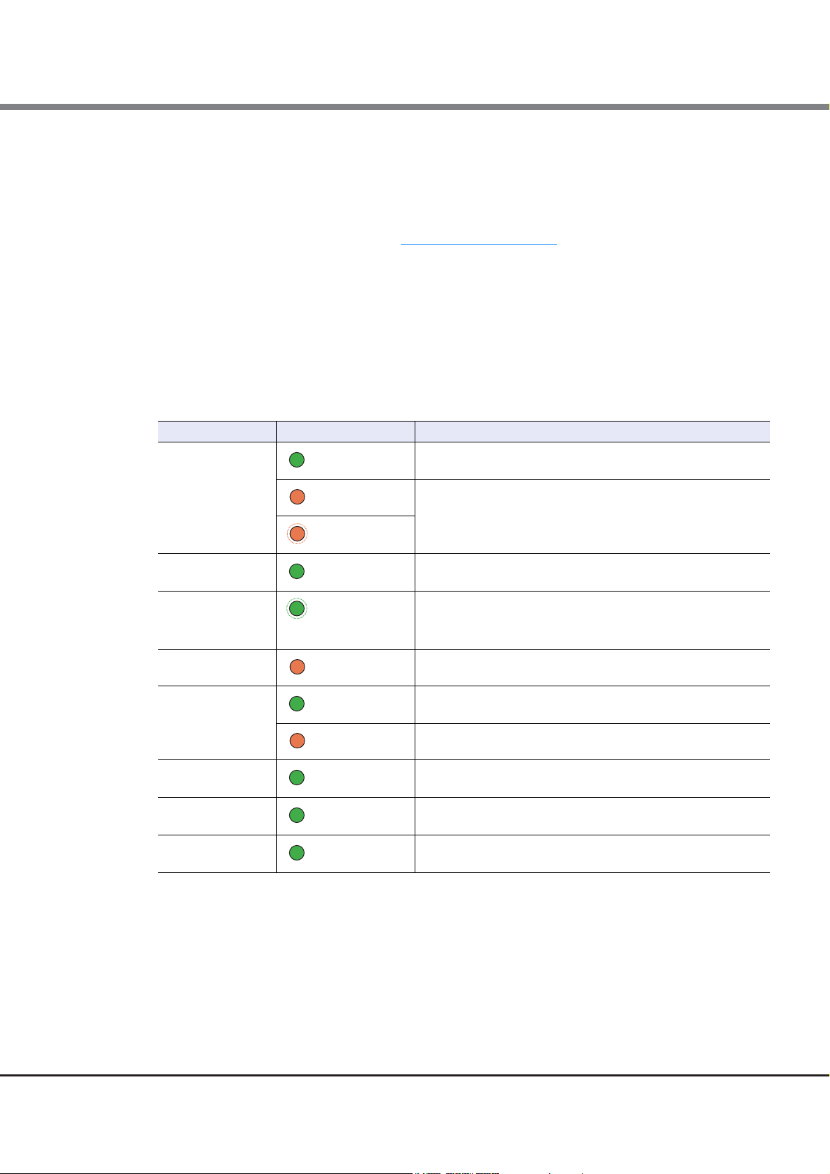
• LEDs
The states of LEDs are listed below.
Table 1.1 Status and meanings of each LED (operation panel (controller enclosure))
POWER
READY
FAULT
MAINT/ID
CACHE
LED name LED status ETERNUS DX Disk storage system status
DC power is supplied to the controller enclosure.
(green)
The ETERNUS DX Disk storage system is available for use.
(green)
The ETERNUS DX Disk storage system is in error status.
(amber)
A part of the ETERNUS DX Disk storage system requires preventive
(blinks amber)
(green)
maintenance.
Maintenance for the ETERNUS DX Disk storage system is in
progress.
• As ordered via ETERNUS Web GUI or ETERNUS CLI, the location
(blinks green)
of the controller enclosure is identified.
• Maintenance or a status check via ETERNUS Web GUI or
ETERNUS CLI is necessary.
There is data in the ETERNUS DX Disk storage system cache
(green)
memory.
15
ETERNUS DX80 S2/DX90 S2 Disk storage system User’s Guide -Operation-
Copyright 2013 FUJITSU LIMITED P3AM-4842-12ENZ0
Page 16

Chapter 1 Components
DRIVE READY LED DRIVE FAULT LED
Slot#8
Slot#9
Slot#10
Slot#11
Slot#12
Slot#13
Slot#14
Slot#15
Slot#0
Slot#1
Slot#2
Slot#3
Slot#4
Slot#5
Slot#6
Slot#7
Slot#16
Slot#17
Slot#18
Slot#19
Slot#20
Slot#21
Slot#22
Slot#23
DRIVE READY LED
DRIVE FAULT LED
Slot#0
Slot#4
Slot#8
Slot#1
Slot#5
Slot#9
Slot#2
Slot#6
Slot#10
Slot#3
Slot#7
Slot#11
1.1 Controller Enclosure
■ Drives
● 2.5" drives
Figure 1.7 2.5" drive
Figure 1.8
shows the slot number of each drive.
Figure 1.8 Drive slot numbers (2.5" type controller enclosure)
● 3.5" drives
Figure 1.9 3.5" drive
Figure 1.10 shows the slot number of each drive.
Figure 1.10 Drive slot numbers (3.5" type controller enclosure)
ETERNUS DX80 S2/DX90 S2 Disk storage system User’s Guide -Operation-
16
Copyright 2013 FUJITSU LIMITED P3AM-4842-12ENZ0
Page 17

Chapter 1 Components
LAN (MNT) port
ACT LEDs
LINK LEDs
DI (OUT) LINKUP LED
READY/FAULT LED
MASTER LEDUNIT ID LED
CA#0 FAULT LED
PWC port
LINK/FAULT LEDs
DI (OUT) port
LAN (RMT) port
Host interface (CA#0)
Host interface (CA#1)
CA#1 FAULT LED
1.1 Controller Enclosure
● Part explanation
• LEDs
The states of LEDs are listed below.
Table 1.2 Status and meanings of each LED (drive)
LED name LED status Drive status
DRIVE READY
DRIVE FAULT
1.1.4 Components (Rear)
(green)
(blinks green)
(amber)
The drive is in normal status.
• The drive is in error status.
• In response to commands from ETERNUS CLI, the location of
the drive is identified.
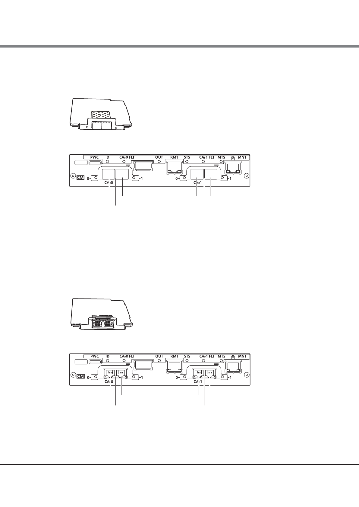
This section describes the controllers and the power supply units in the rear of the controller enclosure.
1.1.4.1 Controllers
The controller contains a CPU, cache memory, System Capacitor Unit (SCU), host interfaces, drive interface (DI)
ports, and LAN ports. The controller controls all operations in the ETERNUS DX Disk storage system.
Figure 1.11 Controller
ETERNUS DX80 S2/DX90 S2 Disk storage system User’s Guide -Operation-
17
Copyright 2013 FUJITSU LIMITED P3AM-4842-12ENZ0
Page 18
Chapter 1 Components
1.1 Controller Enclosure
● Part explanation
• LAN (RMT) port, LAN (MNT) port
These ports are RJ-45 connectors for LAN cables.
• Host interface (CA#0), host interface (CA#1)
Install host interfaces. For details, refer to "Host interfaces" (page 19)
• DI (OUT) port
This port is used to connect a controller enclosure to a drive enclosure with a QSFP cable.
• PWC port
This port is used to connect a power synchronization unit with an RS232C cable.
• LEDs
The states of LEDs are listed below.
Table 1.3 Status and meanings of each LED (controller)
READY/FAULT
MASTER
UNIT ID
CA FAULT
LINK/FAULT
DI (OUT) LINKUP
ACT
LINK
.
LED name LED status Controller status
The controller is in normal status.
(green)
• The controller is performing the initial setup after the power
(amber)
is turned on.
• The controller is in error status.
(blinks amber)
The controller is set as a Master CM.
(green)
• As ordered via ETERNUS Web GUI or ETERNUS CLI, the location
(blinks green)
of the controller is identified.
• System Capacitor Unit (SCU) is charging.
The host interface is in error status.
(amber)
The link between the host interface port and the destination has
(green)
(amber)
(green)
(green)
(green)
been established.
The host interface port is in error status.
The link between the DI (OUT) port and the destination port has
been established.
The controller is sending or receiving data via the LAN port (for
operation management).
The link between the LAN port (for operation management) and
the destination has been established.
18
ETERNUS DX80 S2/DX90 S2 Disk storage system User’s Guide -Operation-
Copyright 2013 FUJITSU LIMITED P3AM-4842-12ENZ0
Page 19

Chapter 1 Components
Port#0 Port#1 Port#0 Port#1
FC iSCSI 10Gbit/s FCoE
Installed host interfaces in the controller
Host interface (CA#0) Host interface (CA#1)
1.1 Controller Enclosure
■ Host interfaces
A host interface is a board that has interface ports to connect a controller to the server.
There are six types of host interfaces: FC 16Gbit/s, FC 8Gbit/s, iSCSI 10Gbit/s, iSCSI 1Gbit/s, FCoE, and SAS.
● FC, iSCSI 10Gbit/s, FCoE (for FC cable connection)
Figure 1.12 Host interface (FC, iSCSI 10Gbit/s, FCoE (for FC cable connection))
• Part explanation
- Host interface ports (FC, iSCSI 10Gbit/s, FCoE (for FC cable connection)) (from left to right: Port#0 and
Port#1 in CA#0, Port#0 and Port#1 in CA#1)
These are the Dual LC connectors to connect FC cables.
19
ETERNUS DX80 S2/DX90 S2 Disk storage system User’s Guide -Operation-
Copyright 2013 FUJITSU LIMITED P3AM-4842-12ENZ0
Page 20
Chapter 1 Components
Port#0 Port#1 Port#0 Port#1
iSCSI 10Gbit/s, FCoE
Installed host interfaces in the controller
Host interface (CA#0)
Host interface (CA#1)
iSCSI 1Gbit/s
Port#0 Port#1Port#0 Port#1
Installed host interfaces in the controller
Host interface (CA#0)
Host interface (CA#1)
1.1 Controller Enclosure
● iSCSI 10Gbit/s, FCoE (for Copper Twinax cable connection)
Figure 1.13 Host interface (iSCSI 10Gbit/s, FCoE (for Copper Twinax cable connection))
• Part explanation
- Host interface ports (iSCSI 10Gbit/s, FCoE (for Copper Twinax cable connection)) (from left to right:
Port#0 and Port#1 in CA#0, Port#0 and Port#1 in CA#1)
These are the connectors to connect Copper Twinax cables.
● iSCSI 1Gbit/s
Figure 1.14 Host interface (iSCSI 1Gbit/s)
• Part explanation
- Host interface ports (iSCSI) (from left to right: Port#0 and Port#1 in CA#0, Port#0 and Port#1 in CA#1)
These are the RJ-45 connectors to connect LAN cables.
20
ETERNUS DX80 S2/DX90 S2 Disk storage system User’s Guide -Operation-
Copyright 2013 FUJITSU LIMITED P3AM-4842-12ENZ0
Page 21

Chapter 1 Components
SAS
Port#0 Port#1Port#0 Port#1
Installed host interfaces in the controller
Host interface (CA#0)
Host interface (CA#1)
Inlet
PSU switch
PSU FAIL LED
AC MISSING LED
POWER LED
FAN FAIL LED
1.1 Controller Enclosure
● SAS
Figure 1.15 Host interface (SAS)
• Part explanation
- Host interface ports (SAS) (from left to right: Port#0 and Port#1 in CA#0, Port#0 and Port#1 in CA#1)
These are the SFF-8088 connectors to connect miniSAS cables.
■ System Capacitor Unit (SCU)
A SCU is installed in a controller as a backup power source in case of power outage.
The SCU is charged from an external power source while the ETERNUS DX Disk storage system is running
normally. If a power outage is detected, data in the cache memory is saved to the non-volatile memory in the
controller using the SCU. The saved data is retained in the non-volatile memory indefinitely.
1.1.4.2 Power Supply Units
The power supply unit transforms input AC power from a power socket to DC power and supplies power to each
component.
Each power supply unit contains fans.
Figure 1.16 Power supply unit
ETERNUS DX80 S2/DX90 S2 Disk storage system User’s Guide -Operation-
Copyright 2013 FUJITSU LIMITED P3AM-4842-12ENZ0
21
Page 22

Chapter 1 Components
1.1 Controller Enclosure
● Part explanation
• Inlet
This inlet is used to connect a power cord.
• PSU switch
This switch is used to turn on and off the AC power supply.
• LEDs
The states of LEDs are listed below.
Table 1.4 Status and meanings of each LED (power supply unit)
(blinks green)
(green)
(off) (off) (off) (off)
(off) (amber) (amber) (off or amber)
(off) (amber) (amber) (amber)
LED name Power supply unit status
POWER PSU FAIL AC MISSING FAN FAIL
(off) (off) (off)
(off) (off) (off)
AC power is supplied to the power
supply unit but the ETERNUS DX Disk
storage system (DC power) is not
turned on.
The power of the ETERNUS DX Disk
storage system (DC power) is turned
on and the power supply unit is
operating normally.
AC power is not supplied to power supply units.
AC power is not supplied to this power
supply unit, but AC power is supplied
to the other power supply unit.
The power supply unit or the fan in the
power supply unit is in error status.
22
ETERNUS DX80 S2/DX90 S2 Disk storage system User’s Guide -Operation-
Copyright 2013 FUJITSU LIMITED P3AM-4842-12ENZ0
Page 23

Chapter 1 Components
LED
Flange cover Flange cover
2.5" disk or 2.5" Solid State Drive (SSD)
DE-ID (drive enclosure number) display panel
Flange cover
3.5" disk or 3.5" Solid State Drive (SSD)
LED
DE-ID (drive enclosure number) display panel
Flange cover
1.2 Drive Enclosures
1.2 Drive Enclosures
LEDs, a DE-ID (drive enclosure number) display panel, and drives are installed on the front side of the drive
enclosure. I/O modules and power supply units are installed in the rear.
There are two types of drive enclosures: a 2.5" type and a 3.5" type.
1.2.1 Front
■ 2.5" type
Figure 1.17 Front view of a 2.5" type drive enclosure
■ 3.5" type
Figure 1.18 Front view of a 3.5" type drive enclosure
23
ETERNUS DX80 S2/DX90 S2 Disk storage system User’s Guide -Operation-
Copyright 2013 FUJITSU LIMITED P3AM-4842-12ENZ0
Page 24
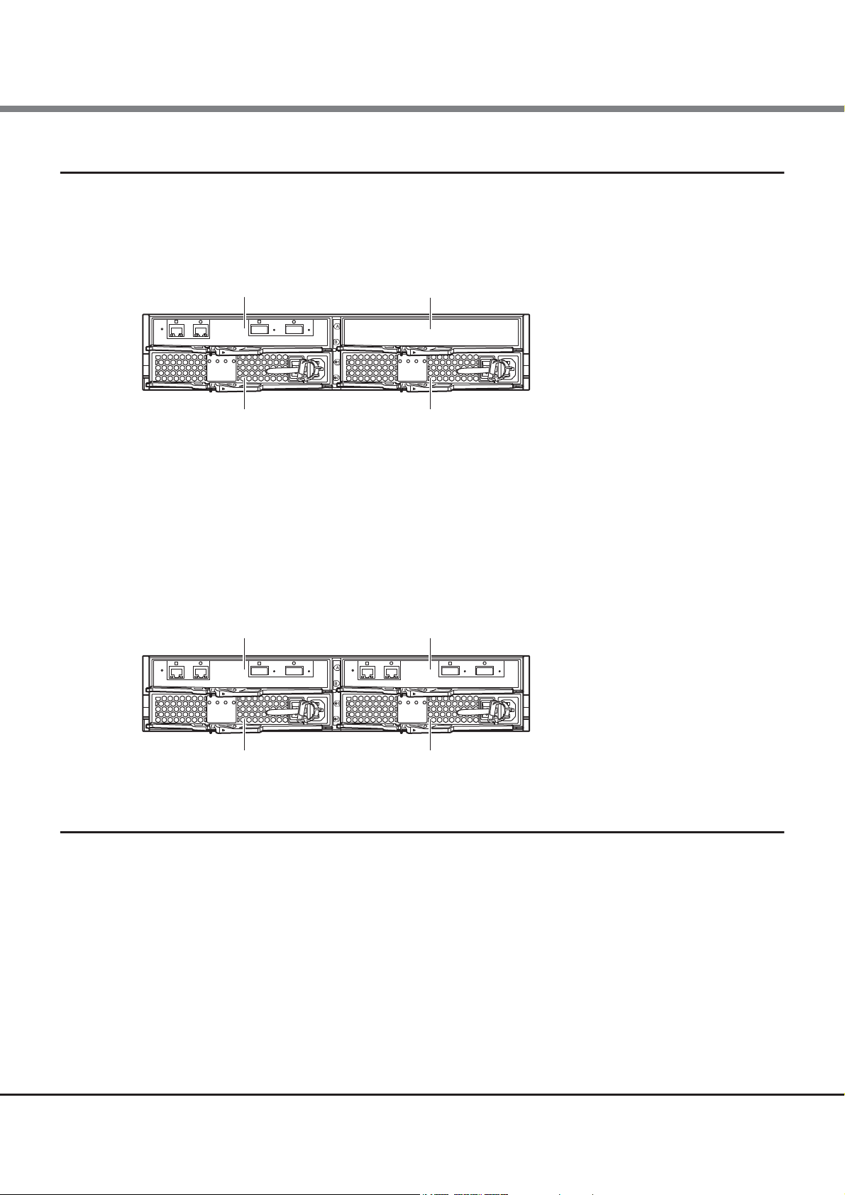
Chapter 1 Components
I/O module (IOM6#0)
Power supply unit (PSU#0) Power supply unit (PSU#1)
Cover
I/O module (IOM6#0)
Power supply unit (PSU#0)
I/O module (IOM6#1)
Power supply unit (PSU#1)
1.2 Drive Enclosures
1.2.2 Rear
■ Single-IOM type
Figure 1.19 Rear view of a drive enclosure (single-IOM type)
● Part explanation
• Cover
Remove this when installing an additional I/O module (optional).
■ Dual-IOM type
Figure 1.20 Rear view of a drive enclosure (dual-IOM type)
1.2.3 Components (Front)
This section describes LEDs, a DE-ID (drive enclosure number) display panel, and drives of the front of the
drive enclosure.
■ DE-ID (drive enclosure number) display panel
The DE-ID (drive enclosure number) of the drive enclosure is displayed.
ETERNUS DX80 S2/DX90 S2 Disk storage system User’s Guide -Operation-
24
Copyright 2013 FUJITSU LIMITED P3AM-4842-12ENZ0
Page 25

Chapter 1 Components
2.5" type 3.5" type
LINE LED
POWER LED
FAULT LED
LINE LED
POWER LED
FAULT LED
DRIVE READY LED DRIVE FAULT LED
1.2 Drive Enclosures
■ LEDs
Figure 1.21 LEDs on the front side of the drive enclosure
The states of LEDs are listed below.
Table 1.5 Status and meanings of each LED (in front of drive enclosure)
LED name LED status Drive enclosure status
LINE
(green)
FAULT
(amber)
POWER
(green)
AC power is supplied to the drive enclosure.
The drive enclosure is in error status.
The drive enclosure is operating normally.
■ Drives
● 2.5" drives
Figure 1.22 2.5" drive
ETERNUS DX80 S2/DX90 S2 Disk storage system User’s Guide -Operation-
25
Copyright 2013 FUJITSU LIMITED P3AM-4842-12ENZ0
Page 26

Chapter 1 Components
Slot#8
Slot#9
Slot#10
Slot#11
Slot#12
Slot#13
Slot#14
Slot#15
Slot#0
Slot#1
Slot#2
Slot#3
Slot#4
Slot#5
Slot#6
Slot#7
Slot#16
Slot#17
Slot#18
Slot#19
Slot#20
Slot#21
Slot#22
Slot#23
DRIVE READY LED
DRIVE FAULT LED
Slot#0
Slot#4
Slot#8
Slot#1
Slot#5
Slot#9
Slot#2
Slot#6
Slot#10
Slot#3
Slot#7
Slot#11
1.2 Drive Enclosures
Figure 1.23 shows the slot number of each drive.
Figure 1.23 Drive slot numbers (2.5" type drive enclosure)
● 3.5" drives
Figure 1.24 3.5" drive
Figure 1.25 shows the slot number of each drive.
Figure 1.25 Drive slot numbers (3.5" type drive enclosure)
● Part explanation
• LEDs
The states of LEDs are listed below.
Table 1.6 Status and meanings of each LED (drive)
LED name LED status Drive status
DRIVE READY
(green)
(blinks green)
DRIVE FAULT
(amber)
The drive is in normal status.
• The drive is in error status.
• In response to commands from ETERNUS CLI, the location of
the drive is identified.
ETERNUS DX80 S2/DX90 S2 Disk storage system User’s Guide -Operation-
26
Copyright 2013 FUJITSU LIMITED P3AM-4842-12ENZ0
Page 27
Chapter 1 Components
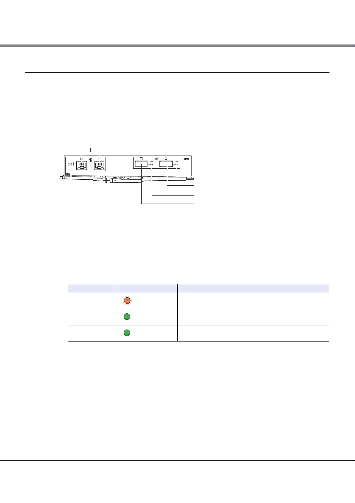
DI (OUT) LINKUP LED
DI (OUT) port
DI (IN) LINKUP LED
DI (IN) port
FAULT LED
These are not used.
1.2 Drive Enclosures
1.2.4 Components (Rear)
This section describes the I/O modules and the power supply units in the rear of the drive enclosure.
■ I/O module
The I/O module is a component that controls how the controller and the drives interact.
Figure 1.26 I/O module
● Part explanation
• DI (OUT) port, DI (IN) port
These ports are connectors for QSFP cables.
• LEDs
The states of LEDs are listed below.
Table 1.7 Status and meanings of each LED (I/O module)
LED name LED status I/O module status
FAULT
(amber)
DI (OUT) LINKUP
(green)
DI (IN) LINKUP
(green)
The I/O module is in error status.
The link between the DI (OUT) port and the destination port has
been established.
The link between the DI (IN) port and the source port has been
established.
ETERNUS DX80 S2/DX90 S2 Disk storage system User’s Guide -Operation-
Copyright 2013 FUJITSU LIMITED P3AM-4842-12ENZ0
27
Page 28
Chapter 1 Components
Inlet
PSU switch
PSU FAIL LED
AC MISSING LED
POWER LED
FAN FAIL LED
1.2 Drive Enclosures
■ Power supply units
The power supply unit transforms input AC power from a power socket to DC power and supplies power to each
component.
Each power supply unit contains fans.
Figure 1.27 Power supply unit
● Part explanation
• Inlet
This inlet is used to connect a power cord.
• PSU switch
This switch is used to turn on and off the AC power supply.
• LEDs
The states of LEDs are listed below.
Table 1.8 Status and meanings of each LED (power supply unit)
LED name Power supply unit status
POWER PSU FAIL AC MISSING FAN FAIL
(green)
(off) (off) (off) (off)
(off) (amber) (amber) (off or amber)
(off) (amber) (amber) (amber)
(off) (off) (off)
AC power is supplied to the power
supply unit.
AC power is not supplied to the power
supply unit.
AC power is not supplied to this power
supply unit, but AC power is supplied
to the other power supply unit.
The power supply unit or the fan in the
power supply unit is in error status.
ETERNUS DX80 S2/DX90 S2 Disk storage system User’s Guide -Operation-
Copyright 2013 FUJITSU LIMITED P3AM-4842-12ENZ0
28
Page 29

Chapter 1 Components
Inlets (INPUT)
Outlets (OUTPUT)
Main line switches
1.3 Power Distribution Units (for Regions other than EMEA&I)
1.3 Power Distribution Units (for Regions other than EMEA&I)
There are two sizes for power distribution units: 1U and 2U.
1.3.1 Power Distribution Units (1U)
The 1U power distribution unit has four outlets and two inlets.
■ Power distribution unit for DX80 S2/DX90 S2 (AC200-240V, 1U, Max 2 enclosures
connection)
Figure 1.28 Power distribution unit for DX80 S2/DX90 S2 (AC200-240V, 1U, Max 2 enclosures connection)
● Part explanation
• Outlet (OUTPUT)
This is a socket (IEC60320-C13) for outgoing power supply. This socket is used to connect a power cord (AC
output cable).
• Inlet (INPUT)
This is a socket (IEC60320-C14) for incoming power supply. This socket is used to connect a power cord (AC
input cable).
• Main line switch
This turns on and off the power distribution unit.
29
ETERNUS DX80 S2/DX90 S2 Disk storage system User’s Guide -Operation-
Copyright 2013 FUJITSU LIMITED P3AM-4842-12ENZ0
Page 30

Chapter 1 Components
Main line switches
Outlets (OUTPUT)
1.3 Power Distribution Units (for Regions other than EMEA&I)
1.3.2 Power Distribution Units (2U)
There are 2U power distribution units that can connect up to six enclosures and 2U power distribution units
that can connect up to eight enclosures.
■ Power distribution unit for DX80 S2/DX90 S2 (AC200-240V, 2U, Max 6 enclosures
connection)
There are 12 outlets.
Figure 1.29 Power distribution unit for DX80 S2/DX90 S2 (AC200-240V, 2U, Max 6 enclosures connection)
● Part explanation
• Outlet (OUTPUT)
This is a socket (IEC60320-C13) for outgoing power supply. This socket is used to connect a power cord (AC
output cable).
• Main line switch
This turns on and off the power distribution unit.
30
ETERNUS DX80 S2/DX90 S2 Disk storage system User’s Guide -Operation-
Copyright 2013 FUJITSU LIMITED P3AM-4842-12ENZ0
Page 31

Chapter 1 Components
Outlets (OUTPUT)
Main line switches
1.3 Power Distribution Units (for Regions other than EMEA&I)
■ Power distribution unit for DX80 S2/DX90 S2 (AC200-240V, 2U, Max 8 enclosures
connection)
There are 16 outlets.
Figure 1.30 Power distribution unit for DX80 S2/DX90 S2 (AC200-240V, 2U, Max 8 enclosures connection)
● Part explanation
• Outlet (OUTPUT)
This is a socket (IEC60320-C13) for outgoing power supply. This socket is used to connect a power cord (AC
output cable).
• Main line switch
This turns on and off the power distribution unit.
31
ETERNUS DX80 S2/DX90 S2 Disk storage system User’s Guide -Operation-
Copyright 2013 FUJITSU LIMITED P3AM-4842-12ENZ0
Page 32

Chapter 2
Main line switch
Basic Operation
This chapter explains how to turn on and off the ETERNUS DX Disk storage system and how to operate the
FUNCTION button on the controller enclosure.
2.1 Powering On and Off
This section explains how to turn on and off the ETERNUS DX Disk storage system.
2.1.1 Switching On and Off the Main Line Switch on the Power Distribution Unit (for Regions Other than EMEA&I)
This section explains how to switch the main line switch of the power distribution unit to ON and OFF.
■ To switch to ON
Turn the main line switch of the power distribution unit to the ON position (marked "I").
Make sure to turn all the main line switches to the ON position.
● For 1U power distribution unit
Figure 2.1 ON position (marked "|") of the main line switches on a 1U power distribution unit
32
ETERNUS DX80 S2/DX90 S2 Disk storage system User’s Guide -Operation-
Copyright 2013 FUJITSU LIMITED P3AM-4842-12ENZ0
Page 33

Chapter 2 Basic Operation
Main line switch
Main line switch
2.1 Powering On and Off
● For 2U power distribution unit
Figure 2.2 ON position (marked "|") of the main line switches on a 2U power distribution unit
■ To switch to OFF
Turn the main line switch of the power distribution unit to the OFF position (marked "O").
If the ETERNUS DX Disk storage system must be turned off, such as before any inspections of power supply
devices are performed, turn off the ETERNUS DX Disk storage system by using the procedure described in
"2.1.4 Powering Off" (page 38)
turn the main line switch to the OFF position.
, turn all the PSU switches of the power supply unit to the OFF position, and
● For 1U power distribution unit
Figure 2.3 OFF position (marked "O") of the main line switches on a 1U power distribution unit
33
ETERNUS DX80 S2/DX90 S2 Disk storage system User’s Guide -Operation-
Copyright 2013 FUJITSU LIMITED P3AM-4842-12ENZ0
Page 34

Chapter 2 Basic Operation
Main line switch
2.1 Powering On and Off
● For 2U power distribution unit
Figure 2.4 OFF position (marked "O") of the main line switches on a 2U power distribution unit
When turning the main line switch to ON (marked "I") right after turning the main line switch to OFF (marked
"O"), turn it back to ON (marked "I") after the POWER LED of the power supply unit has turned off completely.
34
ETERNUS DX80 S2/DX90 S2 Disk storage system User’s Guide -Operation-
Copyright 2013 FUJITSU LIMITED P3AM-4842-12ENZ0
Page 35

Chapter 2 Basic Operation
Power supply unit (PSU#0) Power supply unit (PSU#1)
Drive enclosure
Controller enclosure
2.1 Powering On and Off
2.1.2 Switching On and Off the PSU Switch on the Power Supply Unit
This section explains how to switch the PSU switch of the power supply unit to ON and OFF in each enclosure.
■ To switch to ON
Turn the PSU switch of the power supply unit to the ON position (marked "|").
Make sure all of the PSU switches are in the ON position.
Figure 2.5 ON position (marked "|") of the PSU switch on a power supply unit
AC power is supplied to an enclosure.
• For the controller enclosure, the POWER LED on the power supply unit blinks green.
• For the drive enclosure, the POWER LED on the power supply unit and the LINE LED on the front emit green
lights and the fan revolves at high speed for 30 seconds.
35
ETERNUS DX80 S2/DX90 S2 Disk storage system User’s Guide -Operation-
Copyright 2013 FUJITSU LIMITED P3AM-4842-12ENZ0
Page 36

Chapter 2 Basic Operation
Drive enclosure
Controller enclosure
Power Supply Unit PSU#0 Power Supply Unit PSU#1
2.1 Powering On and Off
■ To switch to OFF
Turn the PSU switch of the power supply unit to the OFF position (marked "O").
For normal operation, there is no need to switch to OFF position.
Figure 2.6 OFF position (marked "O") of the PSU switch on a power supply unit
2.1.3 Powering On
Check that the POWER LED of the power supply unit is off.
This section explains how to turn on the ETERNUS DX Disk storage system.
The following methods can be used to turn the power on:
• Via the Power switch
Press the Power switch to turn on the ETERNUS DX Disk storage system.
• Via the power synchronized unit
Use the power synchronized unit to turn on the ETERNUS DX Disk storage system.
• Via the Wake On LAN function
Use the Wake On LAN function to turn on the power.
36
ETERNUS DX80 S2/DX90 S2 Disk storage system User’s Guide -Operation-
Copyright 2013 FUJITSU LIMITED P3AM-4842-12ENZ0
Page 37

Chapter 2 Basic Operation
Procedure
Controller enclosure
Drive enclosure
Drive enclosure
Power switch
2.1 Powering On and Off
Before turning on the ETERNUS DX Disk storage system, make sure that the main line switches of the power
distribution units and the PSU switches on the power supply units of the ETERNUS DX Disk storage system are
"ON".
Do not turn the main line switches of the power distribution units and the PSU switches on the ETERNUS DX
Disk storage system to the OFF position.
• After turning the power on, it takes about two minutes for the ETERNUS DX Disk storage system to
become READY (i.e. the READY LED turns on). If an error is detected during the initial power-on diagnostic
phase, a longer time (up to ten minutes) may be required before the READY LED turns on.
• Before turning the server on, check that the ETERNUS DX Disk storage system and the network devices
that connect the ETERNUS DX Disk storage system and the server are all in READY status. If the server is
turned on while any of these devices are not in READY status, the server may not be able to recognize the
ETERNUS DX Disk storage system.
• When turning on the power in conjunction with the power synchronized unit, perform the appropriate
waiting process so that the ETERNUS DX Disk storage system is in the READY status before the server is
turned on. Since it takes up to ten minutes before the ETERNUS DX Disk storage system change to READY
status when an error is detected for a component during the initial power-on diagnostic phase, take this
into consideration and specify an appropriate waiting process that is sufficient.
• If the Auto Power function is enabled via ETERNUS Web GUI or ETERNUS CLI, the ETERNUS DX Disk storage
system is automatically turned on when power is supplied to the ETERNUS DX Disk storage system.
• If the Power Resume function is enabled via ETERNUS Web GUI or ETERNUS CLI, the ETERNUS DX Disk
storage system is automatically turned on after the power is restored.
This section explains how to use the Power switch to turn on the ETERNUS DX Disk storage system. For other
procedures, refer to the related manuals.
Before turning on the ETERNUS DX Disk storage system, check that the LINE LEDs of the drive enclosures are
green.
1 Press the Power switch of the controller enclosure.
The POWER LEDs on the controller enclosure and the drive enclosures are turned on.
37
ETERNUS DX80 S2/DX90 S2 Disk storage system User’s Guide -Operation-
Copyright 2013 FUJITSU LIMITED P3AM-4842-12ENZ0
Page 38

Chapter 2 Basic Operation
End of procedure
Controller enclosure
Drive enclosure
Drive enclosure
POWER
READY
FAULT
MAINT/ID
CACHE
LINE
FAULT
POWER
2.1 Powering On and Off
2 After about two minutes, check that the READY LED of the controller enclosure is lit up.
2.1.4 Powering Off
This section explains how to turn off the ETERNUS DX Disk storage system.
The following methods can be used to turn the power off:
• Via the Power switch
Press the Power switch to turn off the ETERNUS DX Disk storage system.
• Via the power synchronized unit
Use the power synchronized unit to turn off the ETERNUS DX Disk storage system.
• Via ETERNUS Web GUI or ETERNUS CLI
Use ETERNUS Web GUI or ETERNUS CLI to turn off the ETERNUS DX Disk storage system.
• When turning off the ETERNUS DX Disk storage system, the power shuts off after the data in the cache
memory is written to the drives. Therefore, it may take one minute (maximum six minutes) for the power
supply to be completely turned off.
• Do not turn off the power of the ETERNUS DX Disk storage system, the network devices that connect the
ETERNUS DX Disk storage system and the server while the server is operating, as this may result in the
loss of data or prevent data from being saved.
• When using a power synchronized unit for power control, make sure to turn off the power with the server.
Even if the ETERNUS DX Disk storage system is turned off by using the Power switch, the power
synchronization function automatically turns on the power.
This section explains how to use the Power switch to turn off the ETERNUS DX Disk storage system. For other
procedures, refer to the related manuals.
38
ETERNUS DX80 S2/DX90 S2 Disk storage system User’s Guide -Operation-
Copyright 2013 FUJITSU LIMITED P3AM-4842-12ENZ0
Page 39

Chapter 2 Basic Operation
Procedure
End of procedure
Controller enclosure
Drive enclosure
Drive enclosure
Power switch
2.2 Using the FUNCTION Button
1 Press and hold the Power switch of the controller enclosure for four seconds or more.
The READY LED of the controller enclosure is turned off.
Press the Power switch only once. If the Power switch is pressed again between the time of the READY
LED turning off and the POWER LED turning off, the ETERNUS DX Disk storage system power may turn
on.
2 The ETERNUS DX Disk storage system power is turned off.
The POWER LEDs on the controller enclosure and the drive enclosures are turned off.
2.2 Using the FUNCTION Button
This section explains how to use the FUNCTION button of the controller enclosure.
The following settings can be performed by using the FUNCTION button:
• Switching the Master CM to the other controller for a dual-controller type
For a dual-controller type, the controller through which the ETERNUS DX Disk storage system is set up and
operated is called the "Master CM", while the other controller is called the "Slave CM".
The single-controller type only has a "Master CM" controller.
• Restoring the factory default settings (network environment settings and firewall settings) of the LAN ports
39
ETERNUS DX80 S2/DX90 S2 Disk storage system User’s Guide -Operation-
Copyright 2013 FUJITSU LIMITED P3AM-4842-12ENZ0
Page 40

Chapter 2 Basic Operation
Procedure
End of procedure
2.2 Using the FUNCTION Button
The following procedure explains how to use the FUNCTION button.
1 Remove the flange cover of the controller enclosure.
2 Change the status of the ETERNUS DX Disk storage system to maintenance status.
Use the pin that is provided with the ETERNUS DX Disk storage system to push down the FUNCTION
button for three seconds.
The ETERNUS DX Disk storage system is in maintenance status when the MAINT/ID LED is green.
3 Use the FUNCTION button to change the following settings:
• Switching the Master CM to the other controller for a dual-controller type
Use the pin to push down the FUNCTION button twice within three seconds.
The MASTER LED for the controller that is set as the Master CM is green.
• Restoring the factory default settings of the LAN ports
Use the pin to push down the FUNCTION button three times within three seconds.
After the default settings of the LAN ports are restored, the MAINT/ID LED blinks green for a few
seconds.
4 Release maintenance status.
Use the pin to push down the FUNCTION button for three seconds.
The ETERNUS DX Disk storage system is not in maintenance status when the MAINT/ID LED is off.
5 Attach the flange cover.
40
ETERNUS DX80 S2/DX90 S2 Disk storage system User’s Guide -Operation-
Copyright 2013 FUJITSU LIMITED P3AM-4842-12ENZ0
Page 41

Chapter 3
Setup
This chapter describes the required settings for operation of the ETERNUS DX Disk storage system and provides
notes for setting up each function of the ETERNUS DX Disk storage system. Note that the Thin Provisioning
function cannot be used for a single-controller type.
3.1 Thin Provisioning Setup
The Thin Provisioning function virtualizes and allocates storage capacity. This reduces physical storage
capacity and unused capacity can be used more efficiently.
The user can start operation of the ETERNUS DX Disk storage system with a small disk capacity by allocating
large virtual disks to the server. Physical disks can be added according to the required capacity without
affecting the server.
The Thin Provisioning balancing function can be used to balance the physical allocation capacity of a Thin
Provisioning Volume (TPV) among RAID groups and to distribute I/O access for the TPV to the RAID groups in
the pool.
In addition, the Thin Provisioning function can be used more efficiently by using the Zero Reclamation
function. The Zero Reclamation function releases physical areas with all zero bits.
To use the Thin Provisioning function, register the Thin Provisioning Feature License in the ETERNUS DX Disk
storage system and set up the Thin Provisioning function.
3.1.1 Registering the Thin Provisioning Feature License
The Thin Provisioning Feature License is a unique license to each ETERNUS DX Disk storage system. This
license cannot be registered in other ETERNUS DX Disk storage systems.
■ For the EMEA&I region
After the Thin Provisioning Feature License is purchased, it is activated by registering a Thin Provisioning
Feature license key in the ETERNUS DX Disk storage system.
When purchasing the Thin Provisioning Feature, a Transaction Authentication Number (TAN) and the URL of
the web-site from which the license key may be obtained are notified by e-mail.
■ For regions other than EMEA&I
When the Thin Provisioning Feature License is purchased separately, register the Thin Provisioning Feature
License in the ETERNUS DX Disk storage system.
For details on how to register the license, refer to the "Feature activation licenses" document that is provided
with the Thin Provisioning Feature License.
41
ETERNUS DX80 S2/DX90 S2 Disk storage system User’s Guide -Operation-
Copyright 2013 FUJITSU LIMITED P3AM-4842-12ENZ0
Page 42

Chapter 3 Setup
3.1 Thin Provisioning Setup
• When the Thin Provisioning Feature License is purchased as a factory-installed option, the license is
registered as a factory setting.
Attach the license label plate provided with the Thin Provisioning Feature License to the rack rail near the
ETERNUS DX Disk storage system which holds its license, for future reference.
• Check whether the license has already been registered using the provided license label plate or the
ETERNUS Web GUI screen. In the following conditions, the license is registered.
- The license key (barcode and 16-character alphanumerical string) is printed on the "LicenseKey" field
of the license label plate.
- In the Thin Provisioning [License] screen of ETERNUS Web GUI, "Registered" is shown in "Status".
3.1.2 Thin Provisioning Setup
For details on the setup and operation management of the Thin Provisioning function, refer to "ETERNUS Web
GUI User’s Guide" or "ETERNUS CLI User’s Guide".
For details on operation management when using ETERNUS SF Storage Cruiser, refer to "ETERNUS SF Storage
Cruiser Operation Guide".
3.1.3 Restrictions and Notes When Using the Thin Provisioning Function
The restrictions and points to note when using the Thin Provisioning function are as follows:
• Storage capacity virtualization
- The maximum number of Thin Provisioning Pools (TPP) is 60 for the ETERNUS DX80 S2 and 120 for the
ETERNUS DX90 S2.
- The maximum TPP capacity is 128TB.
- The maximum Thin Provisioning Volume (TPV) capacity is 128TB. Note that the total TPV capacity must
be smaller than the maximum capacity of the TPP.
- Physical allocation to the created virtual volume is performed in units of 32MB when write operations
from a host to a TPV is performed.
- If the usage of a TPP exceeds the threshold, a notification is sent to the address (SNMP Trap, e-Mail, or
syslog) that is specified by the event notification function of ETERNUS Web GUI or ETERNUS CLI. In
addition, the used capacity can be checked with ETERNUS SF Storage Cruiser. Make sure to add drives to
expand the TPP capacity before insufficient TPP capacity is detected.
- The Thin Provisioning function is unsuitable for using with OSes that write meta-information to all of
the LUNs when creating a file system.
- It is recommended that backing up of a TPV is performed in file units. If a complete backup is
performed, areas that are not allocated to the drives are also backed up as dummy data. The dummy
data is also restored when backed up data is restored for a TPV. If this occurs, drive allocation for the
entire volume capacity is required and the Thin Provisioning function does not work.
- Do not use the Thin Provisioning function when tuning performance.
- The encryption status of a TPP cannot be changed once the TPP is created. To create an encrypted TPP,
specify encryption by firmware when creating the TPP or use Self Encrypting Drives (SED) to configure
the TPP.
42
ETERNUS DX80 S2/DX90 S2 Disk storage system User’s Guide -Operation-
Copyright 2013 FUJITSU LIMITED P3AM-4842-12ENZ0
Page 43

Chapter 3 Setup
3.1 Thin Provisioning Setup
- Caution should be taken when re-recognizing volume capacity dynamically from a server system after
performing TPV capacity expansion with the Thin Provisioning Volume capacity expansion function.
Some platform types (server OS) and versions cannot recognize the expanded volume capacity. To
expand capacity dynamically, refer to the relevant manuals of each OS and file system.
This caution does not apply when creating a new system after TPV capacity expansion.
• Balancing TPV allocation
- Balancing TPV allocation can be performed for TPVs in the same TPP.
- The total number of TPV balancing, FTRP balancing, RAID Migration, and Flexible Tier Migration pro-
cesses that can be performed at the same time is 32.
- TPV balancing cannot be performed at the same time as RAID Migration to a different TPP for which the
target TPV does not belong.
- If RAID groups that cannot perform balancing (such as RAID groups without free capacity) exist in a TPP,
balancing of physical allocation capacity is performed among the other RAID groups in the TPP. If this
occurs, the balancing level after the balancing process is complete may not be "High".
- When TPV balancing is performed, an area for the work volume (the destination TPV which has the
same capacity as the source TPV) is secured in the TPP to which the TPV belongs. As a result, the status
of the TPP may temporarily become alarm status (the TPP usage exceeds the "Caution" or "Warning"
threshold). The alarm status is released when balancing is completed successfully.
- If the capacity of the TPP to which the target TPV belongs is expanded during a TPV balancing process,
the balancing level might be less than before.
- TPV balancing cannot be performed for volumes that are undergoing Zero Reclamation.
• Zero Reclamation
- Zero Reclamation cannot be performed for volumes that are undergoing RAID Migration.
- Zero Reclamation cannot be performed for volumes that are undergoing TPV balancing.
43
ETERNUS DX80 S2/DX90 S2 Disk storage system User’s Guide -Operation-
Copyright 2013 FUJITSU LIMITED P3AM-4842-12ENZ0
Page 44

Chapter 3 Setup
3.2 Flexible Tier (Auto Storage Layering) Setup
3.2 Flexible Tier (Auto Storage Layering) Setup
The automatic storage layering function automatically reallocates data in the ETERNUS DX Disk storage
system according to the data access frequency to optimize performance and costs. This function performs
storage layering by moving frequently accessed data to high speed drives such as SSDs and less frequently
accessed data to cost effective disks with large capacities.
Data is reallocated in smaller units (blocks) than volumes.
Data is redistributed based on the performance information that is monitored and obtained by ETERNUS SF
Storage Cruiser. This function enables Nearline disks to be used while maintaining performance, reducing the
startup cost.
When drives are added to a pool, the physical capacity is allocated unevenly among the RAID groups in the
pool. By using the Flexible Tier Pool balancing function, the allocated physical capacity as well as the usage
rate of the physical disks in the pool can be balanced.
To use the Flexible Tier (auto storage layering) function, register the Thin Provisioning Feature License in the
ETERNUS DX Disk storage system and enable the Flexible Tier function.
3.2.1 Registering the Thin Provisioning Feature License
The Thin Provisioning Feature License is a unique license to each ETERNUS DX Disk storage system. This
license cannot be registered in other ETERNUS DX Disk storage systems.
■ For the EMEA&I region
After the Thin Provisioning Feature License is purchased, it is activated by registering a Thin Provisioning
Feature license key in the ETERNUS DX Disk storage system.
When purchasing the Thin Provisioning Feature, a Transaction Authentication Number (TAN) and the URL of
the web-site from which the license key may be obtained are notified by e-mail.
■ For regions other than EMEA&I
When the Thin Provisioning Feature License is purchased separately, register the Thin Provisioning Feature
License in the ETERNUS DX Disk storage system.
For details on how to register the license, refer to the "Feature activation licenses" document that is provided
with the Thin Provisioning Feature License.
44
ETERNUS DX80 S2/DX90 S2 Disk storage system User’s Guide -Operation-
Copyright 2013 FUJITSU LIMITED P3AM-4842-12ENZ0
Page 45

Chapter 3 Setup
3.2 Flexible Tier (Auto Storage Layering) Setup
• When the Thin Provisioning Feature License is purchased as a factory-installed option, the license is
registered as a factory setting.
Attach the license label plate provided with the Thin Provisioning Feature License to the rack rail near the
ETERNUS DX Disk storage system which holds its license, for future reference.
• Check whether the license has already been registered using the provided license label plate or the
ETERNUS Web GUI screen. In the following conditions, the license is registered.
- The license key (barcode and 16-character alphanumerical string) is printed on the "LicenseKey" field
of the license label plate.
- In the Thin Provisioning [License] screen of ETERNUS Web GUI, "Registered" is shown in "Status".
3.2.2 Flexible Tier Setup
Settings and operation management for the Flexible Tier function are performed with ETERNUS SF Storage
Cruiser.
For details on settings and operation management when using Flexible Tier, refer to "ETERNUS SF Storage
Cruiser Operation Guide for Optimization Option".
3.2.3 Restrictions and Notes
■ When using the Flexible Tier function
The restrictions and points to note when using the Flexible Tier function are as follows:
• Up to 30 Flexible Tier Pools (FTRP) can be registered in an ETERNUS DX Disk storage system.
• Two or three Flexible Tier Sub Pools (FTSP) can be registered in an FTRP. The maximum number of tiers is
three.
• Up to 90 FTSPs can be registered in an ETERNUS DX Disk storage system. Note that the total maximum
number of TPPs and FTSPs is 120. The maximum capacity of an FTSP is 128TB.
• The maximum capacity of a Flexible Tier Volume (FTV) is 128TB. Note that the total capacity of FTVs must
be less than the maximum capacity of FTSPs.
• 32 work volumes (with a physical capacity of 0MB) are created when the Flexible Tier function is enabled.
The maximum number of volumes that can be created in the ETERNUS DX Disk storage system is reduced
by 32.
• To encrypt data, specify encryption for FTRP when creating an FTRP or use Self Encrypting Drives (SED) to
configure the FTSP.
• If usage of an FTRP or an FTV exceeds the threshold, a notification is sent. For FTRPs, a notification (SNMP
Trap, e-mail, or syslog) is also sent to the address that is specified by the event notification setting of
ETERNUS Web GUI or ETERNUS CLI. Make sure to add drives to expand the FTSP capacity by using ETERNUS
SF Storage Cruiser before insufficient FTRP capacity is detected.
45
ETERNUS DX80 S2/DX90 S2 Disk storage system User’s Guide -Operation-
Copyright 2013 FUJITSU LIMITED P3AM-4842-12ENZ0
Page 46

Chapter 3 Setup
3.2 Flexible Tier (Auto Storage Layering) Setup
■ When using the FTRP balancing
The restrictions and points to note when using the FTRP balancing function are as follows:
• Balancing FTRP can be performed for FTSPs in the same TPP.
• The total number of TPV balancing, FTRP balancing, RAID Migration, and Flexible Tier Migration processes
that can be performed at the same time is 32.
• The FTRP balancing function equalizes unevenly allocated physical area in the RAID groups that configure
an FTSP. Note that migrating a physical area to a different FTSP is not available.
• If the free capacity in the FTSP becomes insufficient while FTRP balancing is being performed, an error
occurs and the balancing session ends abnormally. Note that insufficient physical capacity cannot be
replaced by other FTSPs.
• When FTRP balancing is performed, an area for the work volume (the destination FTV which has the same
capacity as the source FTV) is secured in the FTRP to which the FTV belongs. As a result, the status of the
FTRP may temporarily become alarm status (the FTRP usage exceeds the "Caution" or "Warning" threshold).
The alarm status is released when balancing is completed successfully.
• If the capacity of the FTRP is expanded during an FTRP balancing process, the balancing level might be less
than before.
• FTRP balancing cannot be performed for volumes that are undergoing Zero Reclamation.
• FTRP balancing may not be performed regardless of what FTRP balancing level is used. FTRP balancing
availability depends on the physical allocation status of FTVs.
46
ETERNUS DX80 S2/DX90 S2 Disk storage system User’s Guide -Operation-
Copyright 2013 FUJITSU LIMITED P3AM-4842-12ENZ0
Page 47

Chapter 3 Setup
3.3 Storage Migration
3.3 Storage Migration
Storage Migration is a function that migrates the volume data from an old storage system to volumes in a
new storage system without using a server in cases such as when replacing a storage system.
The source storage system and destination ETERNUS DX Disk storage system are physically connected using
cables. Data read from the target volume in the Migration Source is written to the Destination volume in the
ETERNUS DX Disk storage system.
Since Storage Migration is controlled by ETERNUS DX Disk storage system controllers, no additional software
functions are required.
This section describes the restrictions and notes on using Storage Migration.
For details on the Storage Migration procedure, refer to "ETERNUS Web GUI User's Guide".
• Data migration is performed in units of volumes.
• Up to 16 migration source devices can be specified.
• Up to eight migration paths can be created for each migration source device.
• The maximum number of migration volumes for each migration path is 512.
• Storage Migration can be performed when the migration destination device has a larger volume capacity
than the migration source device.
• Volumes for which the volume type (Standard/Open, TPV, or SDV) is available for the host affinity settings
can be specified as migration source volumes.
Standard/Open, WSV, TPV, or FTV type volumes can be specified as migration destination volumes.
• Storage Migration can be performed if the following conditions are satisfied:
- Stop server access to the migration source volumes and the migration destination volumes.
When "Migration + Full Compare" or "Full Compare" is specified for the operation mode, stop the host
access to all of the volumes in the migration destination device.
- Do not specify volumes with existing copy sessions as migration source or migration destination
volumes.
- Do not specify volumes that are being formatted as migration source volumes.
- Do not perform the [Start RAID Group Diagnosis] function or the [Start Disk Diagnosis] function in a
migration source device.
• The FC port mode of the migration destination device must be changed to "Initiator" and the port
parameters must be set.
• The migration paths must be deleted after Storage Migration is complete.
When deletion of the migration paths is complete, change the FC port mode from "Initiator" to "CA" and set
the port parameters. Set the host affinity setting to recognize migration destination volumes from the
server.
47
ETERNUS DX80 S2/DX90 S2 Disk storage system User’s Guide -Operation-
Copyright 2013 FUJITSU LIMITED P3AM-4842-12ENZ0
Page 48

Chapter 3 Setup
3.4 Data Encryption
3.4 Data Encryption
Encrypting data as it is being written to the drive prevents information leakage caused by fraudulent
decoding.
Even if a drive is removed and stolen by malicious third parties, data cannot be decoded.
The encryption function only encrypts the data stored on the drives, so server access results in the
transmission of plain text. Therefore, this function is effective against leakage of data being transferred via
sneaker net, but has no effect on data leakage via server access.
The following two types of data encryption are supported:
• Self Encrypting Drive function
This function encrypts data by using Self Encrypting Drives (SEDs).
SEDs are locked the instant that they are removed from the storage system, which ensures no data is read
or written with these drives. This encryption prevents information leakage from drives that are stolen or
replaced for maintenance. This function also reduces discarding costs because SEDs do not need to be
physically destroyed.
• Volume conversion encryption function
This function encrypts data on a volume basis by using the firmware of the ETERNUS DX Disk storage
system.
Encryption can be performed in volume units according to the importance of the data. No additional
hardware is required to perform volume encryption.
The restrictions and notes on encrypting data are described below.
■ Self Encrypting Drive function
For the procedure to perform data encryption using Self Encrypting Drives (SEDs), refer to "ETERNUS Web GUI
User’s Guide" or "ETERNUS CLI User’s Guide".
• Register the SED authentication key before installing SEDs in the ETERNUS DX Disk storage system. If a SED
is installed without registering the SED authentication key, data leakage in a SED that is removed may
occur.
• The common key can only be set once in the ETERNUS DX Disk storage system. This key can be used for all
the SEDs that are installed in the ETERNUS DX Disk storage system. The common key cannot be changed or
deleted after being set. The common key is used to authenticate RAID groups when key management
server linkage is not used.
48
ETERNUS DX80 S2/DX90 S2 Disk storage system User’s Guide -Operation-
Copyright 2013 FUJITSU LIMITED P3AM-4842-12ENZ0
Page 49

Chapter 3 Setup
3.4 Data Encryption
■ Volume conversion encryption function
For details on the data encryption procedure, refer to "ETERNUS Web GUI User’s Guide" or "ETERNUS CLI User’s
Guide".
• The encryption method for encrypted volumes cannot be changed. Encrypted volumes cannot be changed
to unencrypted volumes.
To change the encryption method or cancel the encryption for a volume, back up the data in the encrypted
volume, delete the encrypted volume, and restore the backed up data.
• It is recommended that the copy source volume and the copy destination volume use the same encryption
method for remote copy between encrypted volumes.
• When copying encrypted volumes (using Advanced Copy or copy operations via server), transfer
performance may not be as good as when copying unencrypted volumes.
• SDPVs cannot be encrypted after they are created. To create an encrypted SDPV, set encryption when
creating a volume.
• Thin Provisioning Volumes (TPVs) cannot be encrypted individually. Rather, the encryption status of TPVs
depends on that of the TPP to which the TPVs belong.
• Flexible Tier Volumes (FTVs) cannot be encrypted individually. Rather, the encryption status of TPVs
depends on that of the Flexible Tier Pool (FTRP) to which the FTVs belong.
49
ETERNUS DX80 S2/DX90 S2 Disk storage system User’s Guide -Operation-
Copyright 2013 FUJITSU LIMITED P3AM-4842-12ENZ0
Page 50

Chapter 3 Setup
LAN
Business server Business server
ETERNUS DX
Disk storage system
Key management server
(Master server)
Key management server
(Slave server)
Replication
SAN
3.5 Key Management Server Linkage
3.5 Key Management Server Linkage
By linking with the key management server, the SEDs and the SED authentication key can be managed
separately and makes it possible to manage the authentication key more securely. Security requirements can
be satisfied by regularly changing the authentication key.
Note that ETERNUS SF KM is required when linking with the key management server.
Figure 3.1 System configuration for linking with the key management server
• To use the authentication key in a key server, a key group needs to be created. Multiple RAID groups can be
registered in a key group. Note that only one key group can be created in each ETERNUS DX Disk storage
system. Only one authentication key can be specified for each key group. The authentication key for a key
group can be changed.
• Setting a period of time for the validity of the authentication key in the key server by using the ETERNUS
DX Disk storage system enables the key to be automatically updated by obtaining a new authentication
key from the key server before the validity of the key expires. Access from the host (server) can be
maintained even if the SED authentication key is changed during operation.
• When linking with the key management server, the ETERNUS DX Disk storage system obtains the SED
authentication key from the key server and performs authentication when key management settings are
performed, key management information is displayed, and any of the following operations are performed.
- Turning on the ETERNUS DX Disk storage system
- Expanding the RAID group capacity (Logical Device Expansion)
- Forcibly enabling a RAID group
- Creating the key group
- Recovering SEDs
- Performing maintenance of drive enclosures
- Performing maintenance of disks
- Applying disk firmware
- Registering Dedicated Hot Spares
- Rebuilding and performing copy back (when using Global Hot Spares)
- Performing a redundant copy (when using Global Hot Spares)
- Turning on the disk motor with the Eco-mode
50
ETERNUS DX80 S2/DX90 S2 Disk storage system User’s Guide -Operation-
Copyright 2013 FUJITSU LIMITED P3AM-4842-12ENZ0
Page 51

Chapter 3 Setup
3.6 Eco-mode
3.6 Eco-mode
Eco-mode is a function that is specifically designed to reduce the power consumption that is characteristic of
Massive Arrays of Idle Disks (MAID).
Eco-mode saves power by managing the scheduled operation times of specified disks and stopping the
motors of disks during periods when they are not required.
The scheduled operation times can be set for each RAID group, Thin Provisioning Pool (TPP), or Flexible Tier
Pool (FTRP) and for operations such as backing up.
If an access occurs while a motor is stopped, the disk is immediately spun up and access proceeds normally
after approximately one to five minutes.
The disk motors can be turned on and off as required by linking the following Storage Foundation Software
ETERNUS SF to Eco-mode.
• ETERNUS SF Storage Cruiser
• ETERNUS SF AdvancedCopy Manager
The following hierarchical storage management software can be also linked with Eco-mode. When using the
Eco-mode function with these software, an Eco-mode disk operating schedule does not need to be set, since
these software turns on the disk motors when stopped disks are accessed.
• IBM Tivoli Storage Manager for Space Management
• IBM Tivoli Storage Manager HSM for Windows
• Dynamic Storage Tiering (DST) function in Symantec Veritas Storage Foundation
The restrictions and notes on using Eco-mode are described below. For details on the Eco-mode procedure,
refer to "ETERNUS Web GUI User’s Guide" or "ETERNUS CLI User’s Guide".
• To set Eco-mode schedule, use ETERNUS Web GUI, ETERNUS CLI, ETERNUS SF Storage Cruiser, or ETERNUS SF
AdvancedCopy Manager (hereinafter, referred to as Storage Foundation Software ETERNUS SF). Note that
schedules that are created by ETERNUS Web GUI or ETERNUS CLI and schedules that are created by Storage
Foundation Software ETERNUS SF cannot be shared. Make sure to use only one type of software to manage
a RAID group.
• Use ETERNUS Web GUI or ETERNUS CLI to set Eco-mode for TPPs and FTRPs. Storage Foundation Software
ETERNUS SF cannot set Eco-mode for TPPs and FTRPs.
• Eco-mode cannot be used for the following drives:
- Global Hot Spares (Eco-mode can be used for Dedicated Hot Spares)
- SSDs
- Unused drives (that are not used by RAID groups)
• For RAID groups, TPPs, or FTRPs disk motors in the following conditions, the Eco-mode schedule cannot be
specified:
- No volumes are registered
- Configured by SSDs
- The RAID group is a RAID group to which the volume with Storage Migration path belongs
- The RAID group is a RAID group that is registered as an REC disk buffer
• For RAID groups in the following conditions, the Eco-mode schedule can be set but the drive motors cannot
be stopped:
- SDPVs are registered
- ODX Buffer volumes are registered
51
ETERNUS DX80 S2/DX90 S2 Disk storage system User’s Guide -Operation-
Copyright 2013 FUJITSU LIMITED P3AM-4842-12ENZ0
Page 52

Chapter 3 Setup
21:009:00
1:00
0:00
Stopped Scheduled Operation Stopped
Disk motors are stopped
ten minutes after the end of
the scheduled operation
Disk motors are spun up
ten minutes before the start of
the scheduled operation
Disk Motors Running
Stopped
Scheduled Operation
Stopped Operation
21:009:00
1:00
Disk Motors RunningDisk Motors Running
Access
Access finishes
Disk motors are
stopped ten minutes
after the end of
the scheduled operation
Disk motors are spun up
ten minutes before the start of
the scheduled operation
Access OK in
one to five minutes
3.6 Eco-mode
• Specify the same Eco-mode schedule for the RAID groups that configure a WSV. If different Eco-mode
schedules are specified, activation of stopped drives when host access is performed occurs and the
response time may increase.
• The operation time of disks varies depending on the Eco-mode schedule and the disk access.
- Access to a stopped disk outside of the scheduled operation time period causes the motor of the
stopped disk to be spun up, allowing normal access in about one to five minutes. When a set time
elapses since the last access to a disk, the motor of the disk is stopped.
- If a disk is activated from the stopped state more than a set amount of times in a day, the Eco-mode
schedule is not applied and disk motors are not stopped by the Eco-mode.
(Example 1) Setting the Eco-mode schedule via ETERNUS Web GUI
Operation schedule is set as 9:00 to 21:00 and there are no accesses outside of the scheduled period
(Example 2) Setting the Eco-mode schedule via ETERNUS Web GUI
Operation schedule is set as 9:00 to 21:00 and there are accesses outside of the scheduled period
• Eco-mode schedules are executed according to the date and time that are set in the ETERUS DX Disk
storage system. To turn on and turn off the disk motors according to the schedule that is set, use the
Network Time Protocol (NTP) server in the date and time setting in ETERNUS Web GUI or ETERNUS CLI to set
automatic adjustment of the date and time.
• Up to eight 2.5" drives or four 3.5" drives can be activated at the same time in a single drive enclosure.
When these maximums are exceeded, the first eight 2.5" drives or four 3.5" drives are activated, followed
by the rest of the drives in matching increments for each size. If the number of drives that are activated in
a single drive enclosure is increased, the time for drive activation takes longer, causing the response times
for the server to increase, which may result in access paths being lost. To prevent this from occurring, the
RAID configuration and drive installation must be taken into consideration.
ETERNUS DX80 S2/DX90 S2 Disk storage system User’s Guide -Operation-
52
Copyright 2013 FUJITSU LIMITED P3AM-4842-12ENZ0
Page 53

Chapter 3 Setup
3.7 Optimizing Volume Configurations
3.7 Optimizing Volume Configurations
The ETERNUS DX Disk storage system allows for the expansion of volumes and RAID group capacities,
migration among RAID groups, and the changing of RAID levels when the volumes are defined.
Exact details depend on the desired operation. Select from the following procedures.
This section describes the restrictions on using each function of the ETERNUS DX Disk storage system and the
notes on setting up each function of the ETERNUS DX Disk storage system.
For details on the above procedures, refer to "ETERNUS Web GUI User’s Guide" or "ETERNUS CLI User’s Guide".
■ Expansion of volume capacity
• RAID Migration (with increased migration destination capacity)
When volume capacity is insufficient, a volume can be moved to a RAID group that has enough free space.
This function is recommended for use when the desired free space is available in the destination.
• LUN Concatenation
Adds areas of free space to an existing volume to expand its capacity. This uses existing free area to
efficiently expand the volume.
■ Expansion of RAID group capacity
• Logical Device Expansion
Adds new drives to an existing RAID group to expand the RAID group capacity. This is used to expand the
existing RAID group capacity instead of adding new RAID group to add the volumes.
■ Migration of RAID groups
• RAID Migration
If the performance of the current RAID groups is not satisfactory due to conflicting volumes, RAID Migration
may be used to improve the performance by redistributing the RAID group configuration.
■ Changing the RAID level
• RAID Migration (to a RAID group with a different RAID level)
Migrating to a RAID group with a different RAID level changes the RAID level of volumes. This is used to
convert the RAID level of all the volumes belonging to a given RAID group.
• Logical Device Expansion (and changing RAID levels when adding the new drives)
The RAID level may also be changed when adding new drives to a RAID group. This is used to convert the
RAID level of all the volumes belonging to a given RAID group.
■ Striping for multiple RAID groups
• Wide Striping
Distributing a single volume to multiple RAID groups makes I/O access from the server more efficient and
improves the performance.
53
ETERNUS DX80 S2/DX90 S2 Disk storage system User’s Guide -Operation-
Copyright 2013 FUJITSU LIMITED P3AM-4842-12ENZ0
Page 54

Chapter 3 Setup
3.7 Optimizing Volume Configurations
3.7.1 RAID Migration
RAID Migration is a function that transfers a volume to a different RAID group while guaranteeing the
integrity of the data. By using RAID Migration, RAID groups and volumes can be hot switched. This allows easy
redistribution of volumes among RAID groups in response to customer needs. The redistribution of volumes
and reconfiguration of RAID groups (e.g. changing the RAID level from RAID5 to RAID1+0) can be performed
while the system is running.
This section describes the restrictions and notes on using RAID Migration.
For details on the RAID Migration procedure, refer to "ETERNUS Web GUI User’s Guide" or "ETERNUS CLI User’s
Guide".
• Volumes can be specified as a target for RAID Migration.
• The total number of RAID Migration, Flexible Tier Migration, TPV balancing, and FTRP balancing processes
that can be performed at the same time is 32.
• The total capacity for RAID Migration, Flexible Tier Migration, TPV balancing, and FTRP balancing processes
that can be performed in at the same time is 128TB.
• The volume types that can be migrated are Standard/Open, TPV, FTV, and WSV. RAID groups, TPPs, FTRPs,
and WSVs can be selected as the RAID Migration destination. If a volume is migrated to a RAID group, it
becomes a Standard/Open volume. If a volume is migrated to a TPP, it becomes a TPV. If a volume is
migrated to an FTRP, it becomes an FTV. If a volume is migrated to a WSV, it becomes a WSV.
• Capacity expansion can be performed at the same time as RAID migration when the RAID Migration source
is a RAID group (Standard/Open) or a WSV and the RAID Migration destination is also a RAID group
(Standard/Open) or a WSV.
Also note that when the RAID Migration source and destination are both WSVs, the number of concatenations for existing RAID groups can be changed.
• Capacity expansion cannot be performed at the same time as RAID migration when the RAID Migration
source is a TPV or an FTV or when the RAID Migration destination is a TPP or an FTRP.
To expand the capacity, use the capacity expansion function of a TPV or an FTV before RAID Migration starts
or after RAID Migration is complete.
• When the RAID Migration destination is a TPP or an FTRP, whether Zero Reclamation is performed after
RAID Migration is complete can be set.
• RAID Migration cannot be performed for volumes that are undergoing Zero Reclamation.
• RAID Migration cannot be performed when the source volume type is "SDV" or "SDPV".
• Select RAID groups under any of the following conditions for the RAID Migration destination:
- The RAID group is not registered as the REC disk buffer.
- The RAID group has an unused area that is more than the capacity of the RAID Migration source
volume.
• TPPs or FTRPs under any of the following conditions cannot be selected as the RAID Migration destination.
- When the capacity of TPP or FTRP is less than the capacity of the RAID Migration source volume (*1)
- When the capacity of the RAID Migration source volume is equal to or larger than the maximum
capacity of TPP for each model (*2)
*1: When the RAID Migration source is a TPV or an FTV, the RAID Migration source volume capacity indicates the
used capacity (physical capacity allocated from a TPP or an FTRP).
*2: This is the total capacity of the TPPs and the FTRPs in the ETERNUS DX Disk storage system.
• RAID levels that are supported by the ETERNUS DX Disk storage system can be set for the source and
destination RAID groups.
• The final volume number (LUN) will be the same as the initial volume number, and from the point of view
of the server, pre-migration, migrating and post-migration volumes are accessed indistinguishably.
54
ETERNUS DX80 S2/DX90 S2 Disk storage system User’s Guide -Operation-
Copyright 2013 FUJITSU LIMITED P3AM-4842-12ENZ0
Page 55

Chapter 3 Setup
3.7 Optimizing Volume Configurations
• During RAID Migration, the access performance for the RAID groups that are specified as the RAID
Migration source and RAID Migration destination may be reduced.
• If the power is turned off or an electrical power outage occurs during RAID Migration, the process will
simply continue when the power is restored.
• When RAID Migration is used to increase the volume (LUN) capacities, note that the increased size of the
expanded volumes may not always be dynamically re-recognized by the server, depending on the serverside OS (type and version) being used. Refer to the applicable OS and file system documentation before
dynamically expanding the volume capacity.
This is not necessary when building a new system after the volume capacity has been expanded.
3.7.2 Logical Device Expansion (LDE)
Logical Device Expansion (LDE) allows the capacity of an existing RAID group to be dynamically expanded by
the addition of extra drives. By expanding the capacity of existing RAID group, a new volume can be added
without having to add new RAID groups.
This section describes the restrictions and notes on using LDE.
For details on the LDE procedure, refer to "ETERNUS Web GUI User’s Guide" or "ETERNUS CLI User’s Guide".
• A RAID group can be specified as a target for LDE.
• Multiple LDEs cannot be performed simultaneously.
• LDE can be performed if the new RAID group capacity is the same or larger than the old capacity.
• Capacity expansion and changing the level of a RAID group can be performed at the same time.
• When adding drives, use drives that have the same capacity and speed as the drives that configure the
target RAID group. If drives of different capacities exist in a RAID group, the smallest capacity becomes the
standard for the RAID group after expansion, and all other drives are regarded as having the same capacity
as the smallest drive. In this case, the remaining drive space is not used. In addition, if drives of different
speeds exist in a RAID group, the access performance of the RAID group is reduced by the slower drives.
• If the drives that configure the target RAID group are SSDs, SSDs must be used when adding drives.
• If the drives that configure the target RAID group are SEDs, SEDs must be used when adding drives.
• LDE can be performed on a RAID group that contains an Advanced Copy target (copy source or copy
destination) volume.
• LDE cannot be performed on a RAID group that belongs to a Thin Provisioning Pool (TPP) or a Flexible Tier
Pool (FTRP).
• LDE cannot be performed for a RAID group in which a Wide Striping Volume (WSV) belongs.
• Since the data cannot be recovered after the failure of LDE, back up all the data of the volumes in the
target RAID group to another area before performing LDE. If LDE fails, recover using this backup data.
• Volumes cannot be added to the target RAID groups while LDE is running. Volumes can be added after LDE
is complete. Volumes cannot be deleted from the target RAID groups while LDE is running.
• If the power is turned off or an electrical power outage occurs during LDE, the process will simply continue
when the power is restored.
55
ETERNUS DX80 S2/DX90 S2 Disk storage system User’s Guide -Operation-
Copyright 2013 FUJITSU LIMITED P3AM-4842-12ENZ0
Page 56

Chapter 3 Setup
3.7 Optimizing Volume Configurations
3.7.3 LUN Concatenation
LUN Concatenation is a function that is used to add new area to a volume and so expand the volume capacity
available to the server. The ability to concatenate widely distributed free areas in the ETERNUS DX Disk
storage system allows efficient use of the drive capacity.
Unused areas, which may be either part or all of a RAID group, are used to create new volumes that are then
added together (concatenated) to form a single large volume.
This section describes the restrictions and notes on using LUN Concatenation.
For details on the LUN Concatenation procedure, refer to "ETERNUS Web GUI User’s Guide" or "ETERNUS CLI
User’s Guide".
• Volumes can be specified as a target for LUN Concatenation.
• Multiple volumes can be concatenated. Up to 16 volumes can be concatenated.
• Maximum concatenated volume capacity is 128TB (*1).
*1: The maximum volume capacity of an ODX Buffer volume is 1TB.
• The minimum required capacity of each volume being concatenated is 1GB.
• Conditions for volumes to be concatenated are as follows:
- Only Standard/Open type volumes can be used for LUN Concatenation. SDV cannot be concatenated.
The encryption status of a concatenated volume is the same status as a volume that is to be
concatenated.
- The RAID levels may be any that are supported by the ETERNUS DX Disk storage system with no need for
all to be the same or any other limitation. It is also possible to connect up volumes with different RAID
levels. Volumes in RAID groups with different types (such as capacity or speed) of drives can be concatenated. However, RAID groups with the same RAID level and same drive type are recommended for concatenated volumes to ensure that performance is not affected.
- LUN Concatenation cannot be performed when the drive type for the RAID group to which the
concatenation source volume belongs and the drive type to which the concatenation target volume
belongs do not match.
• When the concatenation source volume is configured with SAS disks or Nearline SAS disks, volumes
that are configured with SAS disks or Nearline SAS disks can be concatenated.
• When the concatenation source volume is configured with SSDs, volumes that are configured with
SSDs can be concatenated.
• When the concatenation source volume is configured with SEDs, volumes that are configured with
SEDs can be concatenated.
- The same key group setting is recommended for the RAID group to which the concatenation source
volumes belong and the RAID group to which the concatenation destination volumes belong if the
RAID groups are configured with SEDs.
• LUN Concatenation cannot be performed under the following conditions:
- When the volume to be concatenated contains an Advanced Copy session for which the copy range is
"Totally".
- When the volume to be concatenated is a TPV or an FTV.
- When the number of volumes to be concatenated is fewer than the maximum number of volumes that
can be concatenated but the resulting capacity exceeds the maximum single LUN capacity allowed by
the ETERNUS DX Disk storage system.
- When the logical volume to be concatenated is a WSV.
• The encryption status after concatenation is the same as the concatenation source volume.
• It is possible to add extra volumes to an already concatenated volume.
• After concatenation, any number of formatting processes can be started at once.
56
ETERNUS DX80 S2/DX90 S2 Disk storage system User’s Guide -Operation-
Copyright 2013 FUJITSU LIMITED P3AM-4842-12ENZ0
Page 57

Chapter 3 Setup
3.7 Optimizing Volume Configurations
• Because the server-side LUNs are not changed by volume concatenation, an OS reboot is not required.
However, this function only expands the volumes in the ETERNUS DX Disk storage system. Server-side
recognition and capacity expansion is OS dependent.
• The logical unit number of each concatenated volume does not change and remains accessible from the
server before, during, and after the concatenation.
• If the power is turned off or an electrical power outage occurs during LUN Concatenation, the
concatenation will simply continue the next time the power is turned on.
• It is recommended that the data on the volumes that are to be concatenated be backed up first.
• When LUN Concatenation is used to increase the volume (LUN) capacities, note that the increased size of
the expanded volumes may not always be dynamically re-recognized by the server, depending on the
server-side OS (type and version) being used. Refer to the applicable OS and file system documentation
before dynamically expanding the volume capacity.
This is not necessary when building a new system after the volume capacity has been expanded.
• A concatenated volume can be used as an OPC, EC, or QuickOPC copy source or copy destination. It can also
be used as a SnapOPC/SnapOPC+ copy source.
• When a volume that is using ETERNUS SF AdvancedCopy Manager to run backups is expanded via LUN
Concatenation, the volume will need to be registered with ETERNUS SF AdvancedCopy Manager again.
3.7.4 Wide Striping
Wide Striping is a function that improves performance by concatenating multiple RAID groups with striping
and using many drives at the same time. This function is especially effective for systems that require write
access performance.
By increasing the number of drives that configure a LUN, process performance is improved by the distribution
of I/O access from the server to multiple drives.
This section describes the points to note when using the Wide Striping function.
For details on Wide Striping settings, refer to "ETERNUS Web GUI User's Guide" or "ETERNUS CLI User's Guide".
• The maximum volume capacity for a Wide Striping Volume (WSV) is 128TB.
• From 2 to 64 RAID groups can be concatenated.
• Wide Striping cannot be used for RAID groups in the following conditions:
- RAID groups that belong to TPPs or FTRPs
- RAID groups that are registered as REC disk buffers
• The number of RAID groups that are to be concatenated is defined when creating a WSV. The number of
concatenated RAID groups cannot be changed after creation. To change the number of RAID groups in a
WSV, use the RAID Migration function and specify a WSV with a different number of RAID groups as the
RAID Migration destination.
• The LUN Concatenation function cannot be used to expand the WSV capacity. To expand the WSV capacity,
use the RAID Migration function and specify a larger capacity for the RAID Migration destination volume.
• The Logical Device Expansion function cannot be used for RAID groups that configure a WSV.
• Different drive types (SAS, Nearline SAS, SSD, and SED) in RAID groups that configure a WSV cannot be
used.
• Free areas in RAID groups that are concatenated by the Wide Striping function can be used to create other
type volumes (Standard/Open, SDV, SDPV, or WSV).
• WSVs can be created by RAID groups when the stripe size is specified during WSV creation. Note that WSVs
cannot be configured by concatenating RAID groups with different stripe sizes.
57
ETERNUS DX80 S2/DX90 S2 Disk storage system User’s Guide -Operation-
Copyright 2013 FUJITSU LIMITED P3AM-4842-12ENZ0
Page 58

Chapter 4
Operations
This chapter describes the control of the LAN for operation management of the ETERNUS DX Disk storage
system, and the monitoring the status of the ETERNUS DX Disk storage system.
4.1 LAN for Operation Management
The ETERNUS DX Disk storage system must be connected to the LAN for operation management. When remote
support is used, information on errors of the ETERNUS DX Disk storage system or other events can be notified
to the remote support center.
• Make sure to connect each controller to the LAN for operation management.
• The LAN ports of the ETERNUS DX Disk storage system support IPv4 and IPv6.
Note that an IPv6 network is used for an ETERNUS DX Disk storage system with firmware version V10L30
or later.
This section explains how the LAN control controller of the ETERNUS DX Disk storage system operates.
■ LAN control controller (Master CM/Slave CM)
For a dual-controller type, the controller (CM) that is given the authority to manage the LAN is called the
Master CM and the other CM is called the Slave CM.
When an error occurs in the Master CM or LAN, the Master CM is switched automatically.
IP addresses of the LAN ports are not assigned to each controller. These IP addresses are assigned to the role
of master or slave. If the Master CM is switched, the same IP addresses are reused. Therefore, even if the
Master CM is switched and the physical port is changed, access can be maintained via the same IP addresses.
58
ETERNUS DX80 S2/DX90 S2 Disk storage system User’s Guide -Operation-
Copyright 2013 FUJITSU LIMITED P3AM-4842-12ENZ0
Page 59

Chapter 4 Operations
Controller enclosure
MNT
CM#0
Master
CM
MNT
CM#1
Slave
CM
Controller enclosure
MNT
RMT RMT
RMT RMT
CM#0
Slave
CM
MNT
CM#1
Master
CM
IP address A
ETERNUS DX Disk storage system
ETERNUS DX Disk storage system
The Master CM is switched.
CM#0
has failed
IP address A
When the Master CM is
switched, the IP addresses
of the previous Master CM’s
are taken over by the new
Master CM.
Controller enclosure
MNT
CM#0
Master
CM
MNT
CM#1
Slave
CM
RMT
RMT
IP address A IP address B
ETERNUS DX Disk storage system
LAN path
error
The IP address of the Slave CM is used
to switch the Master CM and display
the status of
the ETERNUS DX Disk storage system.
4.1 LAN for Operation Management
Figure 4.1 LAN control (switching of the Master CM)
• Each controller has an LED that lights up green to identify when it is the Master CM.
• Setting the IP address of the Slave CM ensures that ETERNUS Web GUI or ETERNUS CLI can be used from
the Slave CM if an error occurs on the LAN path for the Master CM. The Master CM and the Slave CM
perform different functions. The Slave CM can only switch the Master CM and display the status of the
ETERNUS DX Disk storage system.
The IP address of the Slave CM does not need to be set for normal operation.
Figure 4.2 LAN control (when the IP address of the Slave CM is set)
ETERNUS DX80 S2/DX90 S2 Disk storage system User’s Guide -Operation-
Copyright 2013 FUJITSU LIMITED P3AM-4842-12ENZ0
59
Page 60

Chapter 4 Operations
CAUTION
4.2 Monitoring ETERNUS DX Disk Storage System Status
4.2 Monitoring ETERNUS DX Disk Storage System Status
Check the system status regularly by checking the LEDs of the ETERNUS DX Disk storage system or the status
display function of ETERNUS Web GUI.
Impending trouble may be indicated by the warning message FAULT LEDs of the
ETERNUS DX Disk storage system. The LEDs and the general status of ETERNUS
Web GUI should be checked regularly to prevent any serious trouble from
occurring.
In addition, setting event notification enables e-mail notification messages or SNMP Trap messages for events
that occur in the ETERNUS DX Disk storage system in order to monitor the status of the ETERNUS DX Disk
storage system.
Event notification and status display for the ETERNUS DX Disk storage system can be performed by ETERNUS
CLI. When ETERNUS CLI is used, refer to "ETERNUS CLI User’s Guide".
4.2.1 LED Status Check
The status of the ETERNUS DX Disk storage system can be checked by the LEDs.
If the FAULT LED in front of the ETERNUS DX Disk storage system is amber, contact your maintenance
engineer.
60
ETERNUS DX80 S2/DX90 S2 Disk storage system User’s Guide -Operation-
Copyright 2013 FUJITSU LIMITED P3AM-4842-12ENZ0
Page 61

Chapter 4 Operations
4.2 Monitoring ETERNUS DX Disk Storage System Status
4.2.2 Displaying Status via ETERNUS Web GUI
The status of the ETERNUS DX Disk storage system and the usage status of RAID groups, TPPs, and SDPs can be
checked in the Overview screen of ETERNUS Web GUI.
Figure 4.3 ETERNUS Web GUI screen
Table 4.1
shows the general status.
Status of each component in the ETERNUS DX Disk storage system is monitored periodically, and the result is
displayed as a general status image with character strings.
Table 4.1 General status of ETERNUS Web GUI
General status ETERNUS DX Disk storage system status
The ETERNUS DX Disk storage system is in normal state.
Normal (Green)
"Not Ready" is a status where an abnormality is detected at a power-off,
Not Ready (Red)
Error (Red)
Maintenance (Orange)
Warning (Yellow)
and I/O access from the server cannot be received.
The ETERNUS DX Disk storage system is in error state.
The ETERNUS DX Disk storage system is under maintenance.
The ETERNUS DX Disk storage system is in warning state.
Refer to "ETERNUS Web GUI User’s Guide" for details.
61
ETERNUS DX80 S2/DX90 S2 Disk storage system User’s Guide -Operation-
Copyright 2013 FUJITSU LIMITED P3AM-4842-12ENZ0
Page 62

Chapter 4 Operations
4.2 Monitoring ETERNUS DX Disk Storage System Status
4.2.3 Event Notification
By setting event notification, if an error (event) occurs in the ETERNUS DX Disk storage system, the event
information is notified.
The methods that can be used to notify an event are "e-mail", "SNMP Trap", "syslog", "remote support", and
"host sense".
For the procedure on setting event notification, refer to "User’s Guide -Installation-".
■ E-mail
When an event occurs in the ETERNUS DX Disk storage system, an e-mail is sent to the specified e-mail
address.
For more details on notified event information, refer to "Appendix A Event Notification Message List" (page
103).
■ SNMP Trap
When an event occurs in the ETERNUS DX Disk storage system, an SNMP Trap is sent to the SNMP Manager
(monitoring server).
For more details on event information notified by SNMP Trap, refer to "Appendix A Event Notification Message
List" (page 103).
■ Syslog
When an event occurs in the ETERNUS DX Disk storage system, the event log can be sent to the external server
(syslog server).
For the notified syslog messages, refer to "Appendix A Event Notification Message List" (page 103)
■ Remote Support
The information for errors that occur in the ETERNUS DX Disk storage system is notified to the remote support
center.
■ Host Sense
When an event occurs in the ETERNUS DX Disk storage system, host senses (sense codes) are sent to the
server. For details on sense codes, refer to "Appendix A Event Notification Message List" (page 103)
.
.
62
ETERNUS DX80 S2/DX90 S2 Disk storage system User’s Guide -Operation-
Copyright 2013 FUJITSU LIMITED P3AM-4842-12ENZ0
Page 63

Chapter 4 Operations
SNMP
manager
Mail
server
Syslog
server
ETERNUS DX Disk
storage system
Remote
support
center
REMCS /
AIS Connect
Host sense
Server
(host)
SyslogSNMP TrapE-mail
Syslog serverETERNUS DX Disk storage system
System administrator
Login
Logout
Change settings
↓
↓
Storage system name
User/Role
Operation time
Operation details
Operation result
etc.
Audit log
4.2 Monitoring ETERNUS DX Disk Storage System Status
Figure 4.4 Event notification
4.2.4 Audit Log
By setting audit log, audit trail logs (hereinafter referred to as "audit log") that record performed operations
by using the ETERNUS DX Disk storage system and the system actions that are associated with these
operations can be sent to the syslog server.
For the procedure on setting audit logs, refer to "User’s Guide -Installation-". For audit log information, refer to
"Appendix B Audit Log List" (page 154)
Figure 4.5 Audit logs
.
63
ETERNUS DX80 S2/DX90 S2 Disk storage system User’s Guide -Operation-
Copyright 2013 FUJITSU LIMITED P3AM-4842-12ENZ0
Page 64

Chapter 5
CAUTION
Do Not
Maintaining Optional Products
The following optional products can be installed in the ETERNUS DX Disk storage system:
• Drives
• Drive enclosures
• Host interfaces
• Long wave SFP+ modules
This chapter explains the installation rules, handling instructions, and installation procedures for these
optional products.
Disks, drive enclosures, and Long wave SFP+ modules can be added by users. Users can also replace Short
wave SFP+ modules with Long wave SFP+ modules.
However, make sure to read the manual that contains the safety precautions before performing any of these
procedures.
5.1 Installing Drives
Optional drives can be installed while the ETERNUS DX Disk storage system is running without affecting the
system.
This section explains how to install optional drives.
• Do not uninstall or move a drive that is already installed.
Contact your sales representative or maintenance engineer if a drive needs to
be uninstalled or moved.
64
ETERNUS DX80 S2/DX90 S2 Disk storage system User’s Guide -Operation-
Copyright 2013 FUJITSU LIMITED P3AM-4842-12ENZ0
Page 65

Chapter 5 Maintaining Optional Products
Slot#8
Slot#9
Slot#10
Slot#11
Slot#12
Slot#13
Slot#14
Slot#15
Slot#0
Slot#1
Slot#2
Slot#3
Slot#4
Slot#5
Slot#6
Slot#7
Slot#16
Slot#17
Slot#18
Slot#19
Slot#20
Slot#21
Slot#22
Slot#23
Slot#0
Slot#4
Slot#8
Slot#1
Slot#5
Slot#9
Slot#2
Slot#6
Slot#10
Slot#3
Slot#7
Slot#11
5.1 Installing Drives
5.1.1 Installation Rules for Drives
This section explains the installation rules for drives.
■ 2.5" drives
2.5" drives can be installed in the front side of a 2.5" type controller enclosure or a 2.5" type drive enclosure.
Different types of drives can be installed in the same enclosure. Drives can be installed in any slots of an
enclosure.
Figure 5.1
Figure 5.1 Positions of 2.5" drive slots
shows the positions of 2.5" drive slots.
■ 3.5" drives
3.5" drives can be installed in the front side of a 3.5" type controller enclosure or a 3.5" type drive enclosure.
Different types of drives can be installed in the same enclosure. Drives can be installed in any slots of an
enclosure.
Figure 5.2
shows the positions of 3.5" drive slots.
Figure 5.2 Positions of 3.5" drive slots
5.1.2 Installable Drives
For installable drives, refer to "Product List".
65
ETERNUS DX80 S2/DX90 S2 Disk storage system User’s Guide -Operation-
Copyright 2013 FUJITSU LIMITED P3AM-4842-12ENZ0
Page 66

Chapter 5 Maintaining Optional Products
CAUTION
Do
CAUTION
Do Not
Do
5.1 Installing Drives
5.1.3 Drive Handling Instructions
■ About condensation
• When moving a drive from a cold place, such as an un-conditioned store house
in winter, to a warmer place such as an air-conditioned room, the severe
temperature change may result in condensation forming.
To avoid this, allow the packed drive sufficient time in the warmer place (one
hour for each 15°C of temperature difference) to adapt to the new
temperature.
■ About static electricity
• Do not touch the surface of the board of the drives.
• When handling drives, make sure to wear a wrist strap or touch a metal part to
discharge the human body's natural static electricity. Failure to discharge
static electricity may cause device failure.
• Leave the drive in its package until ready to install it.
66
ETERNUS DX80 S2/DX90 S2 Disk storage system User’s Guide -Operation-
Copyright 2013 FUJITSU LIMITED P3AM-4842-12ENZ0
Page 67

Chapter 5 Maintaining Optional Products
Procedure
CAUTION
Do Not
CAUTION
Do
Do Not
5.1 Installing Drives
■ About shock
• Do not lay the drives directly on a desk or similar hard surface. Always use a
rubber mat or other soft material to cushion the drives against physical
shocks.
• Do not stack drives or stand drives on end.
• Do not apply external force to the interface connectors.
• Do not knock or drop the drives on hard objects.
5.1.4 Additional Drive Installation Procedure
This section describes how to install additional drives in the ETERNUS DX Disk storage system.
• If additional drives are installed in a way other as described here, damage
and/or device failure or electrical shock may occur.
• Do not install drives that are for use in other devices.
■ For 2.5" drives
1 In the [Storage] screen of [Component] on the ETERNUS Web GUI screen, check that all
components of the ETERNUS DX Disk storage system are in normal status.
2 Wear a wrist strap or touch a metal part to discharge the human body’s natural static
electricity.
67
ETERNUS DX80 S2/DX90 S2 Disk storage system User’s Guide -Operation-
Copyright 2013 FUJITSU LIMITED P3AM-4842-12ENZ0
Page 68

Chapter 5 Maintaining Optional Products
Ta b
Dummy drive unit
5.1 Installing Drives
3 Remove the dummy drive unit from the slot in which the drive is to be installed.
Push into the tab of the dummy drive unit and pull it straight out of the drive slot.
The removed dummy drive unit should be retained for future use.
4 Install the new drive.
4-1 Press the catch on the drive lock lever to unlock it.
Catch
Lock lever
4-2 Insert the drive all the way into in the slot, making sure that it is firmly seated and keeping the lock
lever open.
68
ETERNUS DX80 S2/DX90 S2 Disk storage system User’s Guide -Operation-
Copyright 2013 FUJITSU LIMITED P3AM-4842-12ENZ0
Page 69

Chapter 5 Maintaining Optional Products
End of procedure
Procedure
WARNING
Do
Lock lever
5.1 Installing Drives
4-3 Swing the lock lever in the direction of the arrow, until the lock clicks shut.
• Hold the drive with both hands to protect against jarring.
4-4 Check that the newly installed drive's DRIVE READY LED lights up green.
5 Repeat Step 3 and Step 4 for each additional drive.
6 If a wrist strap is used, remove the wrist strap.
7 In the [Disks] screen of [Component] on the ETERNUS Web GUI screen, check that the added
drives have been recognized.
8 Set up RAID groups, volumes, hot spares, and Host Affinity settings on the new drives, as
required.
■ For 3.5" drives
1 In the [Storage] screen of [Component] on the ETERNUS Web GUI screen, check that all
components of the ETERNUS DX Disk storage system are in normal status.
2 Wear a wrist strap or touch a metal part to discharge the human body’s natural static
electricity.
69
ETERNUS DX80 S2/DX90 S2 Disk storage system User’s Guide -Operation-
Copyright 2013 FUJITSU LIMITED P3AM-4842-12ENZ0
Page 70

Chapter 5 Maintaining Optional Products
WARNING
Do
Dummy drive unit
Ta b
Catch
Lock lever
5.1 Installing Drives
3 Remove the dummy drive unit from the slot in which the drive is to be installed.
Push into the tab of the dummy drive unit and pull it straight out of the drive slot.
The removed dummy drive unit should be retained for future use.
4 Install the new drive.
4-1 Press the catch on the drive lock lever to unlock it.
4-2 Insert the drive all the way into in the slot, making sure that it is firmly seated and keeping the lock
lever open.
• Hold the drive with both hands to protect against jarring.
70
ETERNUS DX80 S2/DX90 S2 Disk storage system User’s Guide -Operation-
Copyright 2013 FUJITSU LIMITED P3AM-4842-12ENZ0
Page 71

Chapter 5 Maintaining Optional Products
End of procedure
Lock lever
5.1 Installing Drives
4-3 Swing the lock lever in the direction of the arrow, until the lock clicks shut.
4-4 Check that the newly installed drive's DRIVE READY LED lights up green.
5 Repeat Step 3 and Step 4 for each additional drive.
6 If a wrist strap is used, remove the wrist strap.
7 In the [Disks] screen of [Component] on the ETERNUS Web GUI screen, check that the added
drives are recognized.
8 Set up RAID groups, volumes, hot spares, and Host Affinity settings on the new drives, as
required.
71
ETERNUS DX80 S2/DX90 S2 Disk storage system User’s Guide -Operation-
Copyright 2013 FUJITSU LIMITED P3AM-4842-12ENZ0
Page 72

Chapter 5 Maintaining Optional Products
CAUTION
Do Not
CAUTION
Do
5.2 Installing Drive Enclosures
5.2 Installing Drive Enclosures
Optional drive enclosures can be installed while the ETERNUS DX Disk storage system is running without
affecting the system.
This section explains how to install optional drive enclosures.
• Do not uninstall or move a drive enclosure that is already installed.
Contact your sales representative or maintenance engineer if a drive enclosure
needs to be uninstalled or moved.
5.2.1 Installation Rules for Drive Enclosures
Up to nine drive enclosures can be installed in the ETERNUS DX Disk storage system. 3.5" type drive enclosures
and 2.5" type drive enclosures can be installed in the ETERNUS DX Disk storage system together.
In this case, the maximum number of drives allowed determines the maximum number of drive enclosures
that may be installed.
5.2.2 Installable Drive Enclosures
For installable drive enclosures, refer to "Product List".
5.2.3 Drive Enclosure Handling Instructions
■ About condensation
• When moving a drive enclosure from a cold place, such as an un-conditioned
store house in winter, to a warmer place such as an air-conditioned room, the
severe temperature change may result in condensation forming.
To avoid this, allow the packed drive enclosure sufficient time in the warmer
place (one hour for each 15°C of temperature difference) to adapt to the new
temperature.
72
ETERNUS DX80 S2/DX90 S2 Disk storage system User’s Guide -Operation-
Copyright 2013 FUJITSU LIMITED P3AM-4842-12ENZ0
Page 73

Chapter 5 Maintaining Optional Products
Procedure
CAUTION
Do
CAUTION
Do Not
CAUTION
Do
5.2 Installing Drive Enclosures
■ About static electricity
■ About shock
• When handling drive enclosures, make sure to wear a wrist strap or touch a
metal part to discharge the human body's natural static electricity. Failure to
discharge static electricity may cause device failure.
• Do not handle the drive enclosure roughly or subject it to physical shocks
when laying it down.
• Do not stack the drive enclosures.
• Do not knock or drop the drive enclosure on hard objects.
5.2.4 Additional Drive Enclosure Installation
This section explains how to install additional drive enclosures in the ETERNUS DX Disk storage system.
• If drive enclosures are installed in a way other as described here, damage and/
or device failure or electrical shock may occur.
• Do not install drive enclosures with cables, such as power cords, connected.
• Do not knock the other devices installed in the rack when installing drive
enclosures.
1 In the [Storage] screen of [Component] on the ETERNUS Web GUI screen, check that all
components of the ETERNUS DX Disk storage system are in normal status.
In addition, check the DE-IDs (drive enclosure numbers) of the installed enclosures in the
[Drive Enclosure] screen.
73
ETERNUS DX80 S2/DX90 S2 Disk storage system User’s Guide -Operation-
Copyright 2013 FUJITSU LIMITED P3AM-4842-12ENZ0
Page 74

Chapter 5 Maintaining Optional Products
5.2 Installing Drive Enclosures
2 Display the [Add Drive Enclosure] screen.
2-1 In the [Storage] screen of [Component], click "Add Drive Enclosure" in [Action].
The [Add Drive Enclosure] screen appears.
2-2 Check the DE-ID (drive enclosure number) for the drive enclosure that is to be added in "Target Drive
Enclosure", and click the [Next>>] button.
A screen to show how to install the drive enclosure appears.
3 Wear a wrist strap or touch a metal part to discharge the human body’s natural static
electricity.
74
ETERNUS DX80 S2/DX90 S2 Disk storage system User’s Guide -Operation-
Copyright 2013 FUJITSU LIMITED P3AM-4842-12ENZ0
Page 75

Chapter 5 Maintaining Optional Products
M5 Centering screws (10mm)
2U rack rail
M5 Centering screw (10mm)
M5 Cage nut
M5 Pan head screw (10mm)
5.2 Installing Drive Enclosures
4 Install the drive enclosure in the rack.
4-1 Attach the rack rails to the rack.
■ For the EMEA&I region
(1) Attach the 2U rack rail to the left rear rack pillar.
The M5 centering screws should be inserted in the 1st and 6th holes above the base line of the
controller enclosure.
(2) Insert the pins of the left slide rail in the 1st and 3rd holes from the bottom of the 2U rack rail.
(3) Secure the left slide rail to the front pillar using the M5 centering screw and M5 pan head screw.
(4) For the right slide rail, insert the pins in the holes of the rear pillar, and secure the other side of the
slide rail to the front pillar in the same way as the left slide rail.
ETERNUS DX80 S2/DX90 S2 Disk storage system User’s Guide -Operation-
75
Copyright 2013 FUJITSU LIMITED P3AM-4842-12ENZ0
Page 76

Chapter 5 Maintaining Optional Products
Drive enclosure
1st position
(M5 pan head screw)
3rd position
(M5 centering screw)
1st position
(M5 pan head screw)
3rd position
(M5 centering screw)
2U
Rack rails
Base line of
drive enclosure
[Left] [Right]
2nd position
(M5 cage nut)
2nd position
(M5 cage nut)
(Front rack pillars)
(Rear rack pillars)
Rack rail (for right side)
"R" is stamped on the inner
side of the rack rail
(for right side).
Loosen the M4 screws, and
adjust the rack rails to the depth
of the rack.
[Left]
[Right]
Rack rail (for left side)
"L" is stamped on the inner
side of the rack rail
(for left side).
5.2 Installing Drive Enclosures
(5) Push the M5 cage nuts into the 2nd holes of the front rack pillars above the base line of the drive
enclosure.
The M5 centering screw and M5 pan head screw positions for the slide rails and 2U rack rail are
determined relatively to the base line of the drive enclosure.
Tighten the screws referring to the following figure.
■ For regions other than EMEA&I
(1) Adjust the sizes of the rack rail (for left side) and the rack rail (for right side) to fit the rack.
Loosen the M4 screws to adjust the length of the rack rails to match the distance between the front
and rear rack pillars. Leave the M4 screws slightly unscrewed, as the rack rail must be attached to
the rack before they can be completely tightened.
ETERNUS DX80 S2/DX90 S2 Disk storage system User’s Guide -Operation-
Copyright 2013 FUJITSU LIMITED P3AM-4842-12ENZ0
76
Page 77

Chapter 5 Maintaining Optional Products
(Front rack pillars)
(Rear rack pillars)
Washers
M5 screws
M5 screws
Washers
M5 screws
Plate
M5 screws
Plate
Rack rail (for right side)
Rack rail (for left side)
Front of drive enclosure
Rear of drive enclosure
[Left]
6th position
(M5 screw)
[Left]
1st position
(M5 screw)
5th position
(M5 screw)
2nd position
(M5 screw)
2U
2U
Base line of
drive enclosure
Base line of
drive enclosure
Rack rails
Rack rails
[Right]
[Right]
6th position
(M5 screw)
1st position
(M5 screw)
5th position
(M5 screw)
2nd position
(M5 screw)
5.2 Installing Drive Enclosures
(2) Attach the rack rails to the rack.
Use the two plates to fasten the rack rails to the front rack pillars. Use the four washers to fasten the
rack rails to the rear rack pillars.
Make sure to attach the rack rails and rack pillars so that they fit exactly together without any
space between them.
The M5 screw positions for the rack rails are determined by the drive enclosure base line.
Insert the M5 screws in the 1st and 6th holes on the front rack pillars above the base line and in the
2nd and 5th holes on the rear rack pillars above the base line to fasten the rack rails.
(3) Tighten the M4 screws of the rack rails that were slightly unscrewed in Step (1).
ETERNUS DX80 S2/DX90 S2 Disk storage system User’s Guide -Operation-
77
Copyright 2013 FUJITSU LIMITED P3AM-4842-12ENZ0
Page 78

Chapter 5 Maintaining Optional Products
CAUTION
Do
M5 screw
M5 screw
5.2 Installing Drive Enclosures
4-2 Install the drive enclosure in the rack.
4-3 Fasten the drive enclosure in the rack.
■ For the EMEA&I region
Use two M5 screws to fasten it in the rack pillar.
• When installing or removing the drive enclosure to or from the rack,
make sure that the sides and the bottom of the drive enclosure are held
by two or more people. Failure to do so may cause injury.
78
ETERNUS DX80 S2/DX90 S2 Disk storage system User’s Guide -Operation-
Copyright 2013 FUJITSU LIMITED P3AM-4842-12ENZ0
Page 79

Chapter 5 Maintaining Optional Products
M5 screws
M5 screws
Right front side of the drive enclosure Upper rear side of the drive enclosure
DE_No. label
5.2 Installing Drive Enclosures
■ For regions other than EMEA&I
Use four M5 screws to fasten it in the rack pillar.
4-4 Attach the "DE_No." labels to the positions shown below.
Attach the labels in the same installation order as the drive enclosures (QSFP cable connection
order).
The DE_No. labels are supplied with the ETERNUS DX Disk storage system.
79
ETERNUS DX80 S2/DX90 S2 Disk storage system User’s Guide -Operation-
Copyright 2013 FUJITSU LIMITED P3AM-4842-12ENZ0
Page 80

Chapter 5 Maintaining Optional Products
Right
3.5" type
drive enclosure
2.5" type
drive enclosure
Left
Attachment location of the bracket
2.5" type
drive enclosure
3.5" type
drive enclosure
Bracket
Thumb screw
5.2 Installing Drive Enclosures
4-5 Attach the flange cover that is provided with the ETERNUS DX Disk storage system.
4-6 For regions other than EMEA&I, attach the brackets to the rack rails (for the left and right sides).
Use the thumb screws to attach the brackets at the specified locations on the rear side.
80
ETERNUS DX80 S2/DX90 S2 Disk storage system User’s Guide -Operation-
Copyright 2013 FUJITSU LIMITED P3AM-4842-12ENZ0
Page 81

Chapter 5 Maintaining Optional Products
Controller enclosure
Drive enclosure 1
(Added drive enclosure)
Controller enclosure
Drive enclosure 1
(Added drive enclosure)
Ta b
5.2 Installing Drive Enclosures
5 Connect the added drive enclosure to the previous enclosure with the QSFP cable that is pro-
vided with the ETERNUS DX Disk storage system.
The following figures show the connection paths for QSFP cables when drive enclosure 1 is added.
• For a single-controller type
• For a dual-controller type
• To help with QSFP cable management and prevent incorrect connections, make sure to attach the
destination labels that are supplied with the ETERNUS DX Disk storage system to the connectors of
the QSFP cables.
• When connecting QSFP cables, check the connector orientation and then firmly push it all the way
in.
When disconnecting QSFP cables, use the pull-tab to extract the connector.
81
ETERNUS DX80 S2/DX90 S2 Disk storage system User’s Guide -Operation-
Copyright 2013 FUJITSU LIMITED P3AM-4842-12ENZ0
Page 82

Chapter 5 Maintaining Optional Products
Destination label
IOM (I/O module) number
Drive enclosure number
CM (controller) number
Controller enclosure
Drive enclosure 1
(Added drive enclosure)
5.2 Installing Drive Enclosures
5-1 Attach the destination labels to the connectors of the QSFP cables.
(1) Before attaching the destination labels, check the connection destination of the QSFP cables.
• The connectors on which the "●" symbol is printed are connected to the DI (IN) ports on the
added enclosure.
• The connectors on which the "■" symbol is printed are connected to the DI (OUT) ports on the
enclosure below the added drive enclosure.
(2) Attach the destination labels to the connectors of the QSFP cables.
"Controller number" or "Drive enclosure number - IOM number" is printed on the destination
labels in the "Connection origin DI port → Connection destination DI port" format. The "■" or "●"
symbol is also printed on the destination labels.
Carefully check the connection origin and connection destination. Attach the destination labels
as shown below:
The following figure shows an example of attaching destination labels on the QSFP cables that
connect the controller enclosure to drive enclosure 1.
82
ETERNUS DX80 S2/DX90 S2 Disk storage system User’s Guide -Operation-
Copyright 2013 FUJITSU LIMITED P3AM-4842-12ENZ0
Page 83

Chapter 5 Maintaining Optional Products
Drive enclosure
to be added
Drive enclosure that has
the highest DE-ID
5.2 Installing Drive Enclosures
5-2 Connect the DI (OUT) port of CM#0 or IOM#0 in the enclosure that has the highest DE-ID (drive
enclosure number) to the DI (IN) port of IOM6#0 in the drive enclosure that is to be added.
5-3 Connect the DI (OUT) port of CM#1 or IOM#1 in the enclosure that has the highest DE-ID (drive
enclosure number) to the DI (IN) port of IOM6#1 in the drive enclosure that is to be added.
Perform the same operation as Step 5-2
Do not connect any cable to the last DI (OUT) port on the end.
to connect the QSFP cable.
6 Connect the power cord.
6-1 Connect the power cord to the drive enclosure.
Each enclosure has two power supply units (PSU#0 and PSU#1). The power cords must be
connected to the inlets of both power supply units.
6-2 Connect the power cord plugs to the inlets of the power supply units.
83
ETERNUS DX80 S2/DX90 S2 Disk storage system User’s Guide -Operation-
Copyright 2013 FUJITSU LIMITED P3AM-4842-12ENZ0
Page 84

Chapter 5 Maintaining Optional Products
End of procedure
Controller enclosure
Drive enclosure
POWER
FAULT
FAULT
LINE
5.2 Installing Drive Enclosures
6-3 Fasten the plug of the power cord with the release tie.
Wrap the release tie around the power cord and fasten the release tie from either side. Make sure
that the release tie is not loose.
6-4 Connect the power cord on the power socket side.
Connect the other end of the power cord plug to a power socket or an inlet on the power distribution
unit.
7 Turn the PSU switches of the power supply units (PSU#0 and PSU#1) in the drive enclosure
to the ON position (marked "|").
The power of the drive enclosure is turned on and the fan revolves at high speed for about 30 seconds.
8 Check that the LINE LED and the POWER LED on the drive enclosure are lit up.
9 In the [Add Drive Enclosure] screen, click the [Next>>] button.
The added drive enclosures are recognized and the installation completion screen appears.
10 Click the [Done] button.
The [Add Drive Enclosure] screen closes and the screen display returns to the [Drive Enclosure] screen.
11 In the [Storage] screen of [Component], check that the added drive enclosure is displayed.
12 To install more additional drive enclosures, repeat Step 1 to Step 11.
13 Install the drives.
For details on drive installation, refer to "5.1.4 Additional Drive Installation Procedure" (page 67).
14 If a wrist strap is used, remove the wrist strap.
84
ETERNUS DX80 S2/DX90 S2 Disk storage system User’s Guide -Operation-
Copyright 2013 FUJITSU LIMITED P3AM-4842-12ENZ0
Page 85

Chapter 5 Maintaining Optional Products
CAUTION
Do Not
Do
Host interface 1 (CA#1)
Controller 0 (CM#0)
Expansion
5.3 Installing Host Interfaces
5.3 Installing Host Interfaces
Optional host interfaces can be installed while the ETERNUS DX Disk storage system is running without
affecting the system.
• Do not uninstall or move a host interface that is already installed.
Contact your sales representative or maintenance engineer if a host interface
needs to be uninstalled or moved.
• Contact your maintenance engineer when a host interface is installed in the
host interface 1 (CA#1) of the ETERNUS DX80 S2/DX90 S2.
5.3.1 Installation Rules for Host Interfaces
This section explains the installation rules for host interfaces.
One or two host interfaces that have two host interface ports can be installed for each controller.
Figure 5.3
Install the host interfaces for CA#0 first, and then CA#1. Host interfaces that have different interfaces can be
installed in CA#0 and CA#1.
For a dual-controller type, the configuration is the same for Controller 0 (CM#0) and Controller 1 (CM#1).
■ For a single-controller type
Figure 5.3 Installation diagram for a host interface (single-controller type)
and Figure 5.4 show the installation diagrams for host interfaces.
85
ETERNUS DX80 S2/DX90 S2 Disk storage system User’s Guide -Operation-
Copyright 2013 FUJITSU LIMITED P3AM-4842-12ENZ0
Page 86

Chapter 5 Maintaining Optional Products
Expansion Expansion
Host interface (CA#1) Host interface (CA#1)
Controller 0 (CM#0)
Controller 1 (CM#1)
CAUTION
Do
CAUTION
Do
5.3 Installing Host Interfaces
■ For a dual-controller type
Figure 5.4 Installation diagram for host interfaces (dual-controller type)
5.3.2 Installable Host Interfaces
For installable host interfaces, refer to "Product List".
5.3.3 Host Interface Handling Instructions
■ About condensation
• When moving a host interface from a cold place, such as an un-
conditioned store house in winter, to a warmer place such as an airconditioned room, the severe temperature change may result in
condensation forming.
To avoid this, allow the packed host interface sufficient time in the warmer
place (one hour for each 15°C of temperature difference) to adapt to the
new temperature.
■ About static electricity
• When handling host interfaces, make sure to wear a wrist strap or touch a
metal part to discharge the human body's natural static electricity. Failure
to discharge static electricity may cause device failure.
• Leave the host interface in its package until ready to install it.
86
ETERNUS DX80 S2/DX90 S2 Disk storage system User’s Guide -Operation-
Copyright 2013 FUJITSU LIMITED P3AM-4842-12ENZ0
Page 87

Chapter 5 Maintaining Optional Products
CAUTION
Do Not
5.4 Installing Long Wave SFP+ Modules (16Gbit/s)
■ About shock
• Do not handle the host interface roughly or subject it to physical shocks
when laying it down.
• Do not place any objects on top of the host interface.
• Do not knock or drop the host interface on hard objects.
5.4 Installing Long Wave SFP+ Modules (16Gbit/s)
The Short wave SFP+ module (16Gbit/s) in the host interface (FC 16Gbit/s) can be replaced with an optional
Long wave SFP+ module (16Gbit/s) for an ETERNUS DX Disk storage system.
This section explains the installation rules, handling instructions, and replacement procedure for Long wave
SFP+ modules.
Make sure to read "Safety Precautions" before performing replacement of Long wave SFP+ modules.
Make sure to turn off the ETERNUS DX Disk storage system before replacing SFP+ modules (16Gbit/s).
Contact your sales representative or maintenance engineer to replace SFP+ modules (16Gbit/s) during
system operation.
Long wave SFP+ modules (16Gbit/s) can be installed in an ETERNUS DX Disk storage system with firmware
version V10L50 or later.
5.4.1 Installation Rules for Long Wave SFP+ Modules (16Gbit/s)
One or two Short wave SFP+ modules (16Gbit/s) in a host interface (FC 16Gbit/s) can be replaced with Long
wave SFP+ modules (16Gbit/s).
Short wave SFP+ modules (16Gbit/s) and Long wave SFP+ modules (16Gbit/s) can be mixed in the same host
interface (FC 16Gbit/s).
For the dual controller type, the SFP+ module configurations for controller 0 (CM#0) and controller 1 (CM#1)
must be the same.
87
ETERNUS DX80 S2/DX90 S2 Disk storage system User’s Guide -Operation-
Copyright 2013 FUJITSU LIMITED P3AM-4842-12ENZ0
Page 88

Chapter 5 Maintaining Optional Products
CAUTION
Do
CAUTION
Do
CAUTION
Do Not
5.4 Installing Long Wave SFP+ Modules (16Gbit/s)
5.4.2 Installable Long Wave SFP+ Modules (16Gbit/s)
For installable Long wave SFP+ modules (16Gbit/s), refer to "Product List".
5.4.3 SFP+ Module Handling Instructions
■ About condensation
• When moving an SFP+ module from a cold place, such as an un-conditioned
store house in winter, to a warmer places such as an air-conditioned room, the
severe temperature change may result in condensation forming.
To avoid this, allow the packed SFP+ modules sufficient time in the warmer
place (one hour for each 15°C of temperature difference) to adapt to the new
temperature.
■ About static electricity
■ About shock
• When handling SFP+ modules, make sure to wear a wrist strap or touch a
metal part to discharge the human body's natural static electricity.
Failure to discharge static electricity may cause device failure.
• Leave the SFP+ module in its package until ready to install it.
• Do not handle SFP+ modules roughly or subject them to physical shocks when
laying them down.
• Do not place any objects on top of SFP+ modules.
• Do not knock or drop SFP+ modules on hard objects.
88
ETERNUS DX80 S2/DX90 S2 Disk storage system User’s Guide -Operation-
Copyright 2013 FUJITSU LIMITED P3AM-4842-12ENZ0
Page 89

Chapter 5 Maintaining Optional Products
Procedure
CAUTION
Do
5.4 Installing Long Wave SFP+ Modules (16Gbit/s)
5.4.4 Long Wave SFP+ Modules (16Gbit/s) Installation Procedure
This section describes how to replace a Short wave SFP+ module (16Gbit/s) in the host interface (FC 16Gbit/s)
with a Long wave SFP+ module (16Gbit/s).
• If SFP+ modules are installed in a way other as described here, damage and/or
device failure or electrical shock may occur.
1 Check that all components of the ETERNUS DX Disk storage system are in normal status,
using the [Storage System Status] screen of ETERNUS Web GUI.
2 Check the port location of the Short wave SFP+ module (16Gbit/s) that is to be replaced by
using the Internal Parts information in the [Channel Adapter Detail] screen.
Note that a Short wave SFP+ module (16Gbit/s) is displayed as "16G SFP+(MMF)" in the "SFP Type" field.
3 Turn off the ETERNUS DX Disk storage system.
Refer to "2.1.4 Powering Off" (page 38) for details on how to turn off the ETERNUS DX Disk storage
system.
4 Wear a wrist strap or touch a metal part to discharge the human body's natural static
electricity.
5 Disconnect the FC cable that is connected to the FC port in the Short wave SFP+ module
(16Gbit/s) that is to be replaced.
Push the tab on the FC cable connector and pull out the cable.
Make sure to record the connecting port for the disconnected FC cable.
89
ETERNUS DX80 S2/DX90 S2 Disk storage system User’s Guide -Operation-
Copyright 2013 FUJITSU LIMITED P3AM-4842-12ENZ0
Page 90

Chapter 5 Maintaining Optional Products
Lever
5.4 Installing Long Wave SFP+ Modules (16Gbit/s)
6 Remove the Short wave SFP+ module (16Gbit/s).
6-1 Pull down the Short wave SFP+ module (16Gbit/s) lever.
6-2 Pull the Short wave SFP+ module (16Gbit/s) straight out of the port cage.
Make sure to store the removed Short wave SFP+ module (16Gbit/s) with the fixing lever and the
connector cover attached.
7 Install the Long wave SFP+ module (16Gbit/s).
7-1 Remove the connector cover that is attached to the Long wave SFP+ module (16Gbit/s) port and pull
down the lever.
Keep the removed connector cover in a safe place where they will not be lost.
90
ETERNUS DX80 S2/DX90 S2 Disk storage system User’s Guide -Operation-
Copyright 2013 FUJITSU LIMITED P3AM-4842-12ENZ0
Page 91

Chapter 5 Maintaining Optional Products
CAUTION
Do
Lever
5.4 Installing Long Wave SFP+ Modules (16Gbit/s)
7-2 Insert the Long wave SFP+ module (16Gbit/s) all the way into in the port cage.
7-3 Push up the Long wave SFP+ module (16Gbit/s) lever until it clicks into place.
8 Connect the FC cable that is disconnected in Step 5.
Connect the FC cable connector to the FC port on the Long wave SFP+ module (16Gbit/s).
• When connecting the FC cables, position them so that they will not
obstruct replacement of the power supply unit or controllers by the
maintenance engineer.
9 Repeat Step 5 through Step 8 to replace multiple SFP+ modules (FC 16Gbit/s).
91
ETERNUS DX80 S2/DX90 S2 Disk storage system User’s Guide -Operation-
Copyright 2013 FUJITSU LIMITED P3AM-4842-12ENZ0
Page 92

Chapter 5 Maintaining Optional Products
End of procedure
5.4 Installing Long Wave SFP+ Modules (16Gbit/s)
10 If a wrist strap is used, remove the wrist strap.
11 Turn on the ETERNUS DX Disk storage system.
Refer to "2.1.3 Powering On" (page 36) for details on how to turn on the ETERNUS DX Disk storage
system.
12 Check that the LINK/FAULT LED for the FC port on the replaced Long wave SFP+ module
(16Gbit/s) turns off or lights up green.
13 Start ETERNUS Web GUI to check the status of the newly added Long wave SFP+ module
(16Gbit/s).
On the Internal Parts information in the [Channel Adapter Details] screen of ETERNUS Web GUI, check
that the FC port status is Normal and the SFP type is changed to "16G SFP+(SMF)". In addition, confirm
that all of the other components are in normal status.
92
ETERNUS DX80 S2/DX90 S2 Disk storage system User’s Guide -Operation-
Copyright 2013 FUJITSU LIMITED P3AM-4842-12ENZ0
Page 93

Chapter 6
CAUTION
Do
Maintenance
This chapter describes maintenance for the ETERNUS DX Disk storage system.
6.1 Periodic Backup
In case of a system failure, important data should be regularly backed up.
• We recommend that you backup important data regularly. If the ETERNUS DX
Disk storage system fails and the data has not been backed up, it may be lost.
6.2 Volume Formatting Time
Table 6.1 shows the time for volume formatting (when the volume capacity is 100GB).
Table 6.1 Time for volume formatting (disk)
RAID level Number of
disks
RAID1 2 Approx. 40 minutes/
100GB
RAID1+0 8 Approx. 30 minutes/
100GB
RAID5 5 Approx. 25 minutes/
100GB
RAID5+0 6 Approx. 30 minutes/
100GB
RAID6 6 Approx. 40 minutes/
100GB
*1: The value shows the time required for volume formatting when the volume capacity is 100GB and there is no server
I/O. The time that is required depends on the type and configuration of the disk.
Volume formatting time (*1)
2.5" SAS disks 3.5" SAS disks Nearline SAS disks
Approx. 35 minutes/
100GB
Approx. 25 minutes/
100GB
Approx. 25 minutes/
100GB
Approx. 25 minutes/
100GB
Approx. 30 minutes/
100GB
Approx. 73 minutes/
100GB
Approx. 43 minutes/
100GB
Approx. 49 minutes/
100GB
Approx. 43 minutes/
100GB
Approx. 58 minutes/
100GB
93
ETERNUS DX80 S2/DX90 S2 Disk storage system User’s Guide -Operation-
Copyright 2013 FUJITSU LIMITED P3AM-4842-12ENZ0
Page 94

Chapter 6 Maintenance
6.3 Rebuild/Copyback Process Time
6.3 Rebuild/Copyback Process Time
This section explains the time required for Rebuild/Copyback.
■ Rebuild process time
Table 6.2 shows the time required for the rebuild process (when the volume capacity is 100GB).
Table 6.2 Rebuild process time (disk)
RAID level Number of
disks
RAID1 2 Approx. 27 minutes/
RAID1+0 8 Approx. 7 minutes/
RAID5 5 Approx. 10 minutes/
RAID5+0 6 Approx. 7 minutes/
RAID6 6 Approx. 13 minutes/
*1: The value shows the rebuild process time when the volume capacity is 100GB and there is no server I/O. The time
that is required depends on the type and configuration of the disk.
2.5" SAS disks 3.5" SAS disks Nearline SAS disks
100GB
100GB
100GB
100GB
100GB
Rebuild process time (*1)
Approx. 20 minutes/
100GB
Approx. 5 minutes/
100GB
Approx. 10 minutes/
100GB
Approx. 7 minutes/
100GB
Approx. 13 minutes/
100GB
Approx. 47 minutes/
100GB
Approx. 11 minutes/
100GB
Approx. 15 minutes/
100GB
Approx. 11 minutes/
100GB
Approx. 21 minutes/
100GB
■ Copyback process time
Table 6.3 shows the time required for the copyback process (when the volume capacity is 100GB).
Table 6.3 Copyback process time (disk)
RAID level Number of
disks
RAID1 2 Approx. 27 minutes/
RAID1+0 8 Approx. 7 minutes/
RAID5 5 Approx. 10 minutes/
RAID5+0 6 Approx. 7 minutes/
RAID6 6 Approx. 13 minutes/
*1: The value shows the copyback process time when the volume capacity is 100GB and there is no server I/O. The time
that is required depends on the type and configuration of the disk.
2.5" SAS disks 3.5" SAS disks Nearline SAS disks
100GB
100GB
100GB
100GB
100GB
Copyback process time (*1)
Approx. 20 minutes/
100GB
Approx. 5 minutes/
100GB
Approx. 7 minutes/
100GB
Approx. 5 minutes/
100GB
Approx. 13 minutes/
100GB
Approx. 49 minutes/
100GB
Approx. 11 minutes/
100GB
Approx. 16 minutes/
100GB
Approx. 11 minutes/
100GB
Approx. 20 minutes/
100GB
94
ETERNUS DX80 S2/DX90 S2 Disk storage system User’s Guide -Operation-
Copyright 2013 FUJITSU LIMITED P3AM-4842-12ENZ0
Page 95

Chapter 6 Maintenance
6.4 Maintenance Service
6.4 Maintenance Service
This section explains the ETERNUS DX Disk storage system maintenance service.
When performing maintenance service, the maintenance engineer connects a PC used for maintenance to
the ETERNUS DX Disk storage system. Also, the maintenance engineer may require information that is
necessary for performing maintenance operations.
If the maintenance engineer has any requirement, we ask that they be handled.
6.4.1 Maintenance Support Period
The standard maintenance support period for ETERNUS DX Disk storage system is five years from the date of
purchase, or is defined in your service level agreement (SLA). Contact your sales representative for details if
you prefer to extend the period.
6.4.2 Related Service
■ Remote support
If a possible error that may occur is detected or an error occurs when remote support service is used, the
contents of events are automatically sent to the remote support center and notified to the user.
95
ETERNUS DX80 S2/DX90 S2 Disk storage system User’s Guide -Operation-
Copyright 2013 FUJITSU LIMITED P3AM-4842-12ENZ0
Page 96

Chapter 7
Troubleshooting
This chapter explains troubleshooting when errors occur.
If something unusual occurs during operation (such as the instances listed below), refer to "7.1 Check List"
(page 96) to check the ETERNUS DX Disk storage system status, and contact your maintenance engineer
according to "7.2 Required Information for Inquiries" (page 102)
• When the ETERNUS DX Disk storage system is turned off
• When the ETERNUS DX Disk storage system refuses to turn on
• When the READY LED is not on
• When the FAULT LED is on
• When the FAULT LED blinks
.
• When the ETERNUS DX Disk storage system cannot be connected via a network service
• When the license key cannot be registered
• When I/O access is slow
• When the server does not recognize the volumes
7.1 Check List
■ When the ETERNUS DX Disk storage system is turned off
Check the following points. If none of these resolve the problem, leave the ETERNUS DX Disk storage system
alone and contact your maintenance engineer.
• Is the ETERNUS DX Disk storage system's power cord disconnected?
• Is PSU switch of the power supply unit turned to OFF (O)?
• Has the server been turned off?
If the ETERNUS DX Disk storage system power is in conjunction with the power synchronized unit, the
power of the ETERNUS DX Disk storage system will turn off when the server is turned off.
• Is the main line switch of the power distribution unit turned OFF (O)?
• Is there a power failure?
• Has there been a recent main power failure?
If the Power Resume function is enabled, the ETERNUS DX Disk storage system turns on automatically after
the power is restored.
96
ETERNUS DX80 S2/DX90 S2 Disk storage system User’s Guide -Operation-
Copyright 2013 FUJITSU LIMITED P3AM-4842-12ENZ0
Page 97

Chapter 7 Troubleshooting
Procedure
End of procedure
7.1 Check List
■ When the ETERNUS DX Disk storage system refuses to turn on
Check the following points. If none of these resolve the problem, leave the ETERNUS DX Disk storage system
alone and contact your maintenance engineer.
• Is the ETERNUS DX Disk storage system's power cord disconnected?
• Is PSU switch of the power supply unit turned to OFF (O)?
• Is the main line switch of the power distribution unit turned OFF (O)?
• Is there a power failure?
• Is the QSFP cable disconnected?
■ When the READY LED is not on
If more than ten minutes have passed since the ETERNUS DX Disk storage system's power was turned on and
the READY LED still has not turned on, contact your maintenance engineer.
■ When the FAULT LED is on
Check the general status and the system messages in ETERNUS Web GUI. Perform the necessary actions to
correct the problem. If the problem cannot be resolved, leave the ETERNUS DX Disk storage system alone and
contact your maintenance engineer.
When checking the general status via ETERNUS CLI, refer to "ETERNUS CLI User’s Guide".
• When the general status of ETERNUS Web GUI is
- Check whether one side of the QSFP cable is disconnected. If so, install the connector in the DI port.
- Check if the QSFP cable is connected. If the QSFP cable is not connected, use the following procedure to
connect the QSFP cable.
1 Press the controller enclosure’s Power switch for four seconds or more to turn off the ETERNUS DX
Disk storage system.
Drive enclosures with no QSFP cables connected will remain on.
2 Connect the QSFP cable while the drive enclosure is on.
3 Press the controller enclosure’s Power switch to turn on the ETERNUS DX Disk storage system.
97
ETERNUS DX80 S2/DX90 S2 Disk storage system User’s Guide -Operation-
Copyright 2013 FUJITSU LIMITED P3AM-4842-12ENZ0
Page 98

Chapter 7 Troubleshooting
Procedure
End of procedure
Procedure
End of procedure
7.1 Check List
- Check that the "●" (IN) and "■" (OUT) side of the QSFP cable is connected correctly. If the QSFP cable is
connected incorrectly, use the following procedure to reconnect the QSFP cable.
1 Press the controller enclosure’s Power switch for four seconds or more to turn off the ETERNUS DX
2 Reconnect the QSFP cable.
3 Make sure that power is being supplied, then turn the ETERNUS DX Disk storage system on.
• When the general status of ETERNUS Web GUI is
Check whether the QSFP cables are connected in the correct order or check that the "●" (IN) and "■" (OUT)
side of the QSFP cable is connected correctly. If not, use the following procedure to reconnect the QSFP
cables.
Disk storage system, and turn off the AC power.
1 Press the controller enclosure’s Power switch for four seconds or more to turn off the ETERNUS DX
Disk storage system, and turn off the AC power.
2 Reconnect the QSFP cable.
3 Make sure that power is being supplied, then turn the ETERNUS DX Disk storage system on.
■ When the FAULT LED blinks
Check the general status and the system messages in ETERNUS Web GUI. A general status of
indicates that the ETERNUS DX Disk storage system contains a component that requires preventive
maintenance.
In the details screen for each component, check the detailed information for each component with a and
contact your maintenance engineer.
When checking the general status via ETERNUS CLI, refer to "ETERNUS CLI User’s Guide".
98
ETERNUS DX80 S2/DX90 S2 Disk storage system User’s Guide -Operation-
Copyright 2013 FUJITSU LIMITED P3AM-4842-12ENZ0
Page 99

Chapter 7 Troubleshooting
Procedure
7.1 Check List
■ When the ETERNUS DX Disk storage system cannot be connected via a network service
Check the following points. If none of these resolve the problem, contact your maintenance engineer.
• Is the ETERNUS DX Disk storage system turned off?
• Has the LAN cable become disconnected? For a dual-controller type, does the controller to which the LAN
cable is connected have an unlit MASTER LED?
• Have any network devices (such as LAN switch or router) failed? Are the network device settings invalid?
• Are the environment settings for the network service invalid?
• Is the IP address incorrect?
• Are the settings for the ETERNUS DX Disk storage system LAN ports (firewall) invalid?
If the problem is not resolved, follow the procedure below to restore the default values for the ETERNUS DX
Disk storage system network environment settings and the firewall settings.
Note that the settings (network environment settings and firewall settings) for all of the LAN ports are
initialized after the following procedure is performed.
1 Remove the flange cover of the controller enclosure.
2 Change the status of the ETERNUS DX Disk storage system to maintenance status.
Use the pin that is provided with the ETERNUS DX Disk storage system to push down the FUNCTION
button for three seconds.
The ETERNUS DX Disk storage system is in maintenance status when the MAINT/ID LED is green.
99
ETERNUS DX80 S2/DX90 S2 Disk storage system User’s Guide -Operation-
Copyright 2013 FUJITSU LIMITED P3AM-4842-12ENZ0
Page 100

Chapter 7 Troubleshooting
End of procedure
7.1 Check List
3 Use the pin to push down the FUNCTION button three times within three seconds.
After the default settings of the LAN ports are restored, the MAINT/ID blinks green for a few seconds.
4 Release maintenance status.
Use the pin to push down the FUNCTION button for three seconds.
The MAINT/ID LED turns off.
5 Access ETERNUS Web GUI or ETERNUS CLI by using the default IP address to perform the
network environment settings and the firewall settings.
Make sure to enable the firewall setting for the protocol that is used for each service.
• To use ETERNUS Web GUI, enable the http or https connection. If not, the ETERNUS DX Disk storage
system cannot connect to the network via GUI.
• To use ETERNUS CLI, enable the telnet or SSH connection. If not, the ETERNUS DX Disk storage
system cannot connect to the network via CLI.
• To use the "ping" command for the ETERNUS DX Disk storage system, enable the ICMP connection.
If not, the ETERNUS DX Disk storage system does not respond to the "ping" command.
• To use monitoring software, enable the Maintenance Secure connection. If not, the ETERNUS DX
Disk storage system cannot connect to the network via monitoring software.
• To use the SNMP Manager, enable the SNMP connection. If not, the ETERNUS DX Disk storage
system does not respond to SNMP access.
6 Check whether the ETERNUS DX Disk storage system can connect to each service.
If it cannot connect, contact your maintenance engineer.
■ When the license key cannot be registered
A wrong serial number may have been input when issuing the license key. If the problem persists, contact
your sales representatives.
When issuing the license key again, make sure to check that the [Serial number] (ETERNUS DX Disk storage
system serial number) that is described in the notification e-mail is correct.
■ When I/O access is slow
Check the following points. When the cause is not identified, contact your maintenance engineer.
• Check that the ambient temperature does not exceed the operating environment conditions.
If so, Nearline SAS drive performance may be reduced.
• Click the icon of each part on the [Storage] screen of [Component] of ETERNUS Web GUI to check if an
abnormality is detected in ETERNUS DX Disk storage system parts.
If an abnormality is detected, contact your maintenance engineer.
100
ETERNUS DX80 S2/DX90 S2 Disk storage system User’s Guide -Operation-
Copyright 2013 FUJITSU LIMITED P3AM-4842-12ENZ0
 Loading...