

Page 1

FUJITSU Storage
ETERNUS DX60 S4,
ETERNUS DX60 S3
Hybrid Storage Systems
Operation Guide (Basic)
P3AM-9012-08ENZ0
Operation management/maintenance
Page 2

Table of Contents
1. Component Names and LED Names 9
Controller Enclosures ...................................................................................................................... 9
Front .......................................................................................................................................................................9
Rear ......................................................................................................................................................................10
Components (Front) .............................................................................................................................................11
ETERNUS DX60 S4 Components (Rear) ..................................................................................................................14
ETERNUS DX60 S3 Components (Rear) ..................................................................................................................17
Drive Enclosures ........................................................................................................................... 22
Front .....................................................................................................................................................................22
Rear ......................................................................................................................................................................23
Components (Front)..............................................................................................................................................24
Components (Rear) ..............................................................................................................................................26
Power Distribution Units (for Regions other than the EMEIA, Central American, and Caribbean Re-
gions) ........................................................................................................................................... 29
Power Distribution Units (1U) ...............................................................................................................................29
Power Distribution Units (2U) ...............................................................................................................................30
2. Basic Operation 32
Powering On and Off..................................................................................................................... 32
Switching On and Off the Main Line Switch on the Power Distribution Unit (for Regions other than the EMEIA,
Central American, and Caribbean Regions)...........................................................................................................32
Switching On and Off the PSU Switch on the Power Supply Unit............................................................................36
Powering On .........................................................................................................................................................38
Powering Off .........................................................................................................................................................39
Using the FUNCTION Button.......................................................................................................... 41
3. Storage System Monitoring 43
Checking LED Status...................................................................................................................... 43
Displaying Status via ETERNUS Web GUI ....................................................................................... 43
Displaying Status via ETERNUS CLI ................................................................................................ 44
Event Notification ......................................................................................................................... 44
Audit Log ...................................................................................................................................... 45
2
FUJITSU Storage ETERNUS DX60 S4, ETERNUS DX60 S3 Hybrid Storage Systems Operation Guide (Basic)
Copyright 2018 FUJITSU LIMITED
P3AM-9012-08ENZ0
Page 3

Table of Contents
4. Component Expansion/Function Enhancement 47
Installing Additional Drives........................................................................................................... 47
Installable Drives ..................................................................................................................................................47
Drive Handling Instructions...................................................................................................................................47
Additional Drive Installation Procedure.................................................................................................................48
Installing Additional Drive Enclosures........................................................................................... 54
Installable Drive Enclosures ..................................................................................................................................54
Drive Enclosure Handling Instructions...................................................................................................................54
Additional Drive Enclosure Installation Procedure.................................................................................................56
Adding Servers.............................................................................................................................. 69
RAID Group Creation..............................................................................................................................................69
Volume Creation ...................................................................................................................................................70
Connection Setup ..................................................................................................................................................71
5. Maintenance 76
Periodic Backup ............................................................................................................................ 76
Maintenance Service..................................................................................................................... 76
Maintenance Support Period.................................................................................................................................76
Replacing Batteries ...............................................................................................................................................76
Related Service......................................................................................................................................................77
6. Troubleshooting 78
Check List...................................................................................................................................... 78
Required Information for Inquiries................................................................................................ 86
3
FUJITSU Storage ETERNUS DX60 S4, ETERNUS DX60 S3 Hybrid Storage Systems Operation Guide (Basic)
Copyright 2018 FUJITSU LIMITED
P3AM-9012-08ENZ0
Page 4

List of Figures
Figure 1 Front View of a 2.5" Type Controller Enclosure............................................................................................9
Figure 2 Front View of a 3.5" Type Controller Enclosure............................................................................................9
Figure 3 Rear View of a Controller Enclosure (When Only One Controller Is Installed)............................................10
Figure 4 Rear View of a Controller Enclosure (When Two Controllers Are Installed)................................................10
Figure 5 Operation Panel (Controller Enclosure) ....................................................................................................11
Figure 6 2.5" Drives................................................................................................................................................13
Figure 7 Drive Slot Numbers (2.5" Type Controller Enclosure) ................................................................................13
Figure 8 3.5" Drives................................................................................................................................................13
Figure 9 Drive Slot Numbers (3.5" Type Controller Enclosure) ................................................................................13
Figure 10 Controllers................................................................................................................................................14
Figure 11 Power Supply Unit (Controller Enclosure).................................................................................................17
Figure 12 Controllers................................................................................................................................................18
Figure 13 Power Supply Unit (Controller Enclosure).................................................................................................21
Figure 14 Front View of a 2.5" Type Drive Enclosure.................................................................................................22
Figure 15 Front View of a 3.5" Type Drive Enclosure.................................................................................................22
Figure 16 Rear View of a Drive Enclosure (When Only One I/O Module Is Installed) .................................................23
Figure 17 Rear View of a Drive Enclosure (When Two I/O Modules Are Installed).....................................................23
Figure 18 Operation Panel (Drive Enclosure) ...........................................................................................................24
Figure 19 2.5" Drives................................................................................................................................................25
Figure 20 Drive Slot Numbers (2.5" Type Drive Enclosure) .......................................................................................25
Figure 21 3.5" Drives................................................................................................................................................25
Figure 22 Drive Slot Numbers (3.5" Type Drive Enclosure) .......................................................................................25
Figure 23 I/O Module ...............................................................................................................................................26
Figure 24 Power Supply Unit (Drive Enclosure) ........................................................................................................28
Figure 25 Power Distribution Unit (AC200-240V, 1U, 4 Outlets)...............................................................................29
Figure 26 Power Distribution Unit (AC200-240V, 1U, 4 Outlets)...............................................................................29
Figure 27 Power Distribution Unit (AC200-240V, 2U, 12 Outlets).............................................................................30
Figure 28 Power Distribution Unit (AC200-240V, 2U, 16 Outlets).............................................................................30
Figure 29 Power Distribution Unit (AC200-240V, 2U, 16 Outlets).............................................................................31
Figure 30 ON Position (Marked "|") of the Main Line Switches on a 1U Power Distribution Unit ..............................32
Figure 31 ON Position of the Main Line Switches on a 1U Power Distribution Unit ..................................................32
Figure 32 ON Position (Marked "|") of the Main Line Switches on a 2U Power Distribution Unit ..............................33
Figure 33 ON Position of the Main Line Switches on a 2U Power Distribution Unit ..................................................33
Figure 34 OFF Position (Marked "¡") of the Main Line Switches on a 1U Power Distribution Unit ...........................34
Figure 35 OFF Position of the Main Line Switches on a 1U Power Distribution Unit .................................................34
Figure 36 OFF Position (Marked "¡") of the Main Line Switches on a 2U Power Distribution Unit ...........................35
Figure 37 OFF Position of the Main Line Switches on a 2U Power Distribution Unit .................................................35
Figure 38 ON Position (Marked "|") of the PSU Switch on a Power Supply Unit ........................................................36
Figure 39 OFF Position (Marked "¡") of the PSU Switch of a Power Supply Unit ......................................................37
Figure 40 ETERNUS Web GUI Screen.........................................................................................................................43
Figure 41 Event Notification ....................................................................................................................................45
Figure 42 Audit Log..................................................................................................................................................46
4
FUJITSU Storage ETERNUS DX60 S4, ETERNUS DX60 S3 Hybrid Storage Systems Operation Guide (Basic)
Copyright 2018 FUJITSU LIMITED
P3AM-9012-08ENZ0
Page 5

List of Tables
Table 1 Status and Meanings of Each LED (Operation Panel (Controller Enclosure)) ............................................11
Table 2 Status and Meanings of Each LED (Drive (Controller Enclosure)) .............................................................14
Table 3 Status and Meanings of Each LED (Controller) .........................................................................................16
Table 4 Status and Meanings of Each LED (Power Supply Unit (Controller Enclosure)).........................................17
Table 5 Status and Meanings of Each LED (Controller) .........................................................................................19
Table 6 Status and Meanings of Each LED (Power Supply Unit (Controller Enclosure)).........................................21
Table 7 Status and Meanings of Each LED (Operation Panel (Drive Enclosure)) ...................................................24
Table 8 Status and Meanings of Each LED (Drive (Drive Enclosure)).....................................................................26
Table 9 Status and Meanings of Each LED (I/O Module) .......................................................................................26
Table 10 Status and Meanings of Each LED (Power Supply Unit (Drive Enclosure)) ................................................28
Table 11 General Status of ETERNUS Web GUI.........................................................................................................43
Table 12 General Status of ETERNUS CLI .................................................................................................................44
5
FUJITSU Storage ETERNUS DX60 S4, ETERNUS DX60 S3 Hybrid Storage Systems Operation Guide (Basic)
Copyright 2018 FUJITSU LIMITED
P3AM-9012-08ENZ0
Page 6

Preface
Fujitsu would like to thank you for purchasing the FUJITSU Storage ETERNUS DX60 S4, ETERNUS DX60 S3 (hereinafter referred to as ETERNUS DX).
The ETERNUS DX is designed to be connected to Fujitsu servers (Fujitsu SPARC Servers, PRIMEQUEST, or PRIMERGY) or non-Fujitsu servers.
This manual describes the operation management and maintenance of the ETERNUS DX.
This manual is intended for use of the ETERNUS DX in regions other than Japan.
Please carefully review the information outlined in this manual.
Eighth Edition
April 2018
6
FUJITSU Storage ETERNUS DX60 S4, ETERNUS DX60 S3 Hybrid Storage Systems Operation Guide (Basic)
Copyright 2018 FUJITSU LIMITED
P3AM-9012-08ENZ0
Page 7
Preface
Trademarks
Third-party trademark information related to this product is available at:
http://www.fujitsu.com/global/products/computing/storage/eternus/trademarks.html
About This Manual
Intended Audience
This manual is intended for storage system administrators or system administrators who manage and maintain
the ETERNUS DX.
Related Information and Documents
The latest version of this manual and the latest information for your model are available at:
http://www.fujitsu.com/global/support/products/computing/storage/disk/manuals/
Refer to the following manuals of your model as necessary:
"Configuration Guide -Server Connection-"
"Configuration Guide (Power Synchronized Unit)"
Document Conventions
■
Third-Party Product Names
Oracle Solaris may be referred to as "Solaris", "Solaris Operating System", or "Solaris OS".
•
•
Microsoft® Windows Server® may be referred to as "Windows Server".
■
Notice Symbols
The following notice symbols are used in this manual:
Indicates information that you need to observe when using the ETERNUS storage system.
Make sure to read the information.
Indicates information and suggestions that supplement the descriptions included in this
manual.
7
FUJITSU Storage ETERNUS DX60 S4, ETERNUS DX60 S3 Hybrid Storage Systems Operation Guide (Basic)
Copyright 2018 FUJITSU LIMITED
P3AM-9012-08ENZ0
Page 8

Electric Shock
No Disassembly
Unplug
Warning level indicator
Warning type indicator
Warning details
• To avoid damaging the ETERNUS storage system, pay attention to the
following points when cleaning the ETERNUS storage system:
Warning layout ribbon
Example warning
- Make sure to disconnect the power when cleaning.
- Be careful that no liquid seeps into the ETERNUS storage system
when using cleaners, etc.
- Do not use alcohol or other solvents to clean the ETERNUS storage system.
CAUTION
Do
Preface
Warning Signs
Warning signs are shown throughout this manual in order to prevent injury to the user and/or material damage.
These signs are composed of a symbol and a message describing the recommended level of caution. The following explains the symbol, its level of caution, and its meaning as used in this manual.
The following symbols are used to indicate the type of warnings or cautions being described.
This symbol indicates the possibility of serious or fatal injury if the ETERNUS DX is not used
properly.
This symbol indicates the possibility of minor or moderate personal injury, as well as damage to the ETERNUS DX and/or to other users and their property, if the ETERNUS DX is not
used properly.
This symbol indicates IMPORTANT information for the user to note when using the ETERNUS
DX.
The triangle emphasizes the urgency of the WARNING and CAUTION contents. Inside the
triangle and above it are details concerning the symbol (e.g. Electrical Shock).
The barred "Do Not..." circle warns against certain actions. The action which must be
avoided is both illustrated inside the barred circle and written above it (e.g. No Disassembly).
The black "Must Do..." circle indicates actions that must be taken. The required action is
both illustrated inside the black disk and written above it (e.g. Unplug).
How Warnings are Presented in This Manual
A message is written beside the symbol indicating the caution level. This message is marked with a vertical ribbon in the left margin, to distinguish this warning from ordinary descriptions.
A display example is shown here.
FUJITSU Storage ETERNUS DX60 S4, ETERNUS DX60 S3 Hybrid Storage Systems Operation Guide (Basic)
Copyright 2018 FUJITSU LIMITED
8
P3AM-9012-08ENZ0
Page 9

1. Component Names and LED Names
1
3 3
2
1
3 3
2
This chapter provides the component names of the ETERNUS DX.
Controller Enclosures
An operation panel and drives are installed in the front of the controller enclosure. Controllers and power supply
units are installed in the rear.
Note that some LED names of the controllers are different in the ETERNUS DX60 S4 and the ETERNUS DX60 S3.
Front
This section provides the names of the components on the front of a controller enclosure.
■
2.5" Type
Figure 1 Front View of a 2.5" Type Controller Enclosure
Operation panel
1.
2. 2.5" drive
3. Flange cover
■
3.5" Type
Figure 2 Front View of a 3.5" Type Controller Enclosure
Operation panel
1.
2. 3.5" drive
3. Flange cover
9
FUJITSU Storage ETERNUS DX60 S4, ETERNUS DX60 S3 Hybrid Storage Systems Operation Guide (Basic)
Copyright 2018 FUJITSU LIMITED
P3AM-9012-08ENZ0
Page 10
1
2
34
1
2
34
1. Component Names and LED Names
Controller Enclosures
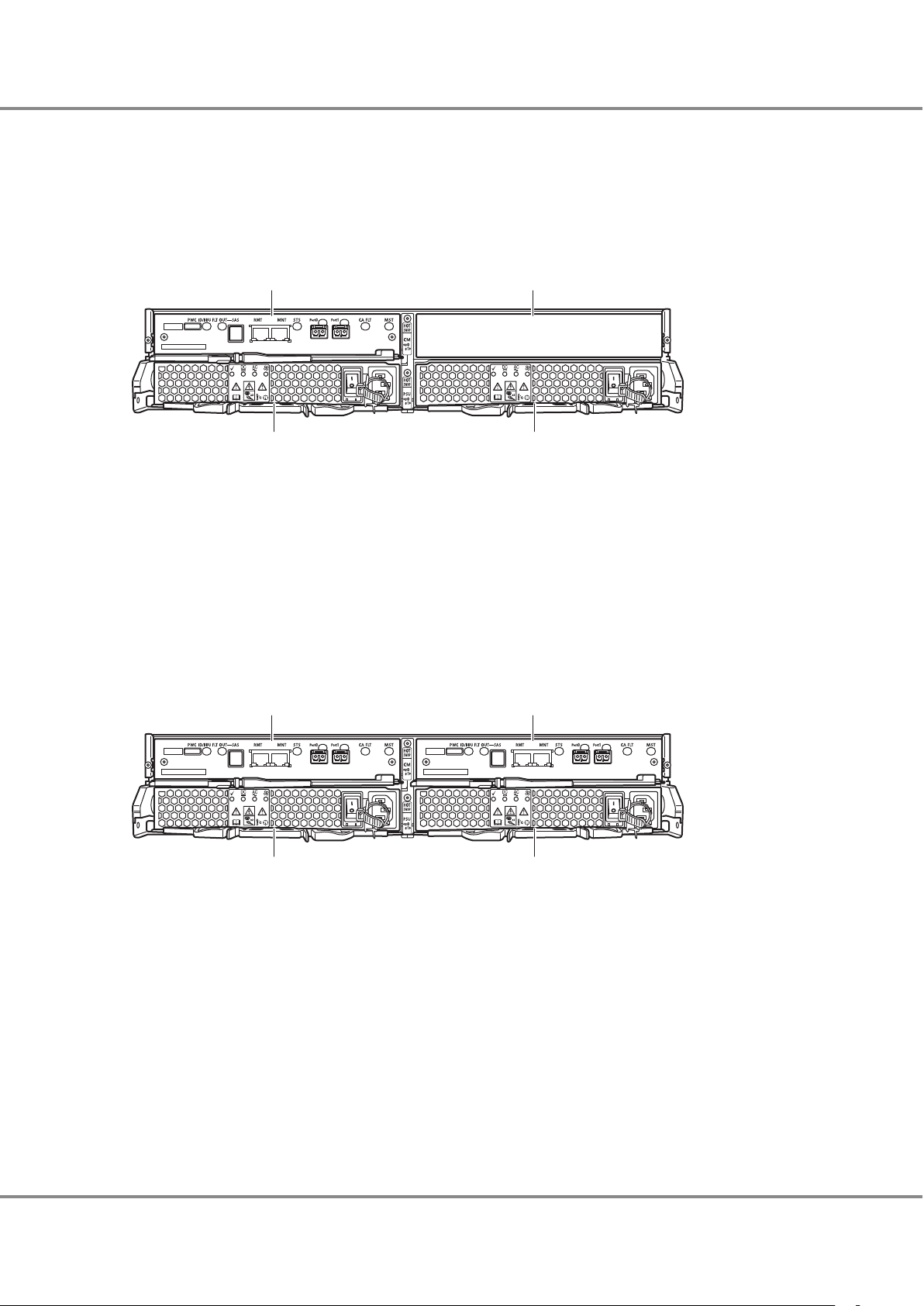
Rear
This section provides the names of the components on the rear of a controller enclosure.
■
When Only One Controller Is Installed
Figure 3 Rear View of a Controller Enclosure (When Only One Controller Is Installed)
1.
Controller (CM#0)
2. Cover
Remove this when installing an additional controller (optional).
3. Power supply unit (PSU#0)
4. Power supply unit (PSU#1)
■
When Two Controllers Are Installed
Figure 4 Rear View of a Controller Enclosure (When Two Controllers Are Installed)
Controller (CM#0)
1.
2. Controller (CM#1)
3. Power supply unit (PSU#0)
4. Power supply unit (PSU#1)
10
FUJITSU Storage ETERNUS DX60 S4, ETERNUS DX60 S3 Hybrid Storage Systems Operation Guide (Basic)
Copyright 2018 FUJITSU LIMITED
P3AM-9012-08ENZ0
Page 11

2
3
1
4
5
6
7
2
3
1
4
5
6
7
8
A
B
1. Component Names and LED Names
Controller Enclosures
Components (Front)
This section describes the operation panel and the drives in the front of the controller enclosure.
■
Operation Panel
An operation panel has LEDs, a Power switch, and a FUNCTION button.
Figure 5 shows the operation panel. Table 1 shows the status and meanings of each LED.
Figure 5 Operation Panel (Controller Enclosure)
A.
With a flange cover
B. Without a flange cover
1. Power switch
This switch is used to turn on or off the ETERNUS DX.
2. POWER LED
3. IDENTIFY LED
4. FAULT LED
5. MAINTENANCE LED
6. CACHE LED
7. READY LED
8. FUNCTION button
This button is used to switch the maintenance status on or off, to switch the master CM (when two controllers
are mounted), to initialize the LAN ports, or to initialize the user settings.
The LEDs turn on or blink to indicate the statuses that are listed below.
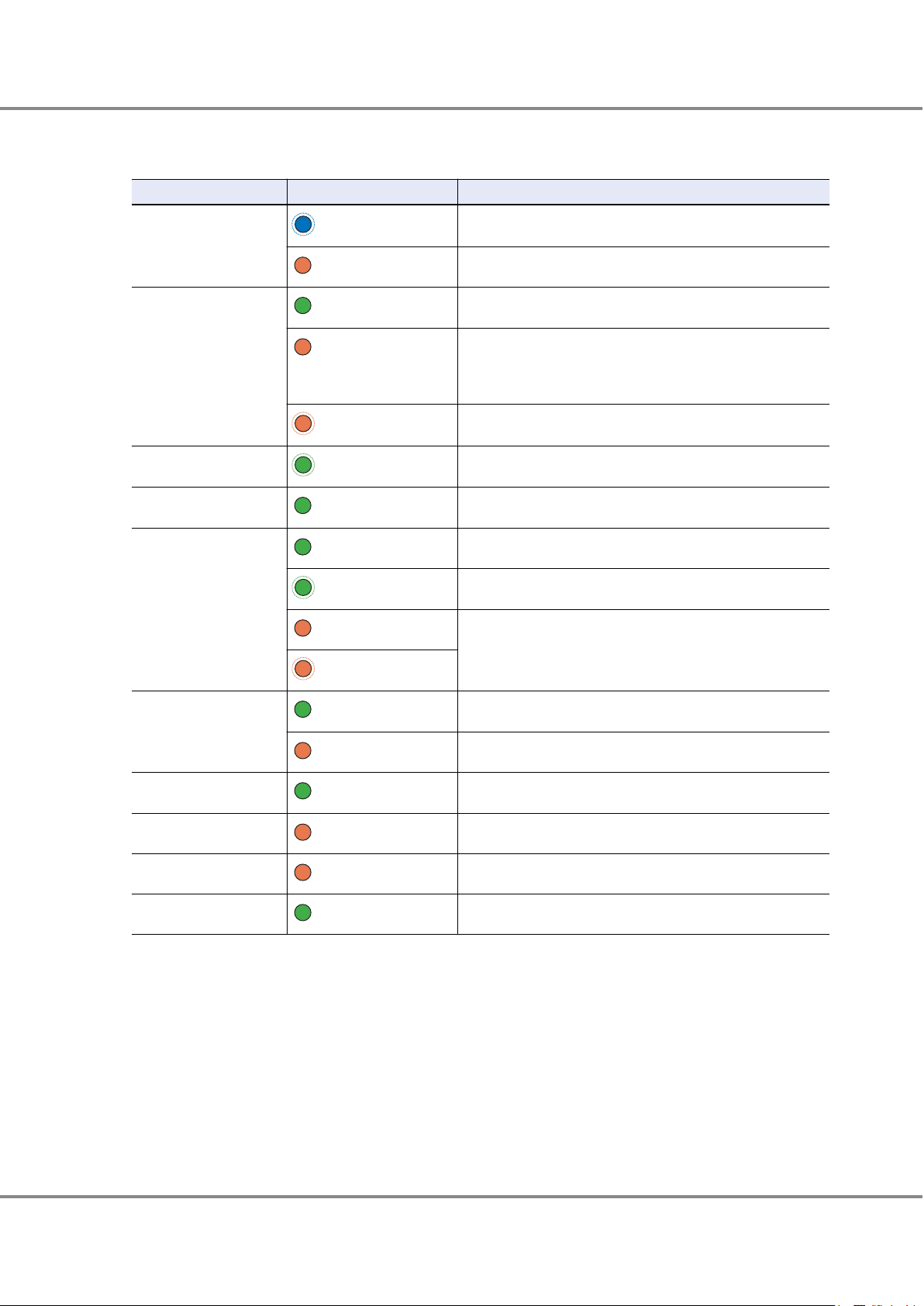
Table 1 Status and Meanings of Each LED (Operation Panel (Controller Enclosure))
LED name
POWER
LED status Meaning
(green)
DC power is supplied to the controller enclosure.
IDENTIFY
FUJITSU Storage ETERNUS DX60 S4, ETERNUS DX60 S3 Hybrid Storage Systems Operation Guide (Basic)
(blinks blue)
Copyright 2018 FUJITSU LIMITED
The installation location of the controller enclosure is identified
according to the instruction that is issued from ETERNUS Web GUI
or ETERNUS CLI.
11
P3AM-9012-08ENZ0
Page 12
1. Component Names and LED Names
Controller Enclosures
LED name LED status Meaning
FAULT
(amber)
The ETERNUS DX is in error status.
MAINTENANCE
CACHE
READY
(blinks amber)
(green)
(blinks green)
(green)
(green)
A part of the ETERNUS DX requires preventive maintenance.
Maintenance for the ETERNUS DX is in progress.
Maintenance (from ETERNUS Web GUI or ETERNUS CLI) for the
ETERNUS DX is in progress or a status check of the ETERNUS DX is
necessary.
There is data in the cache memory of the ETERNUS DX.
The ETERNUS DX is available for use.
12
FUJITSU Storage ETERNUS DX60 S4, ETERNUS DX60 S3 Hybrid Storage Systems Operation Guide (Basic)
Copyright 2018 FUJITSU LIMITED
P3AM-9012-08ENZ0
Page 13
12
Slot#8
Slot#9
Slot#10
Slot#11
Slot#12
Slot#13
Slot#14
Slot#15
Slot#0
Slot#1
Slot#2
Slot#3
Slot#4
Slot#5
Slot#6
Slot#7
Slot#16
Slot#17
Slot#18
Slot#19
Slot#20
Slot#21
Slot#22
Slot#23
1
2
Slot#0
Slot#4
Slot#8
Slot#1
Slot#5
Slot#9
Slot#2
Slot#6
Slot#10
Slot#3
Slot#7
Slot#11
1.
Component Names and LED Names
Controller Enclosures
■
Drives
● 2.5" Drives
Figure 6 shows the 2.5" drive. Figure 7 shows the slot number of each 2.5" drive.
Table 2 shows the status and meanings of each LED.
Figure 6 2.5" Drives
1.
DRIVE READY LED
2. DRIVE FAULT LED
Figure 7 Drive Slot Numbers (2.5" Type Controller Enclosure)
● 3.5" Drives
Figure 8 shows the 3.5" drive. Figure 9 shows the slot number of each 3.5" drive.
Table 2 shows the status and meanings of each LED.
Figure 8 3.5" Drives
DRIVE READY LED
1.
2. DRIVE FAULT LED
Figure 9 Drive Slot Numbers (3.5" Type Controller Enclosure)
13
FUJITSU Storage ETERNUS DX60 S4, ETERNUS DX60 S3 Hybrid Storage Systems Operation Guide (Basic)
Copyright 2018 FUJITSU LIMITED
P3AM-9012-08ENZ0
Page 14

1234
5
1614 15
171617
18 22 23
SAS 6Gbit/s SAS 12Gbit/s
FC
iSCSI 1Gbit/s
iSCSI 10Gbit/s
6
8
10711
12 13
9
19 19
19 19 19 19
2020
2121
8
9
20
21
20
21
1. Component Names and LED Names
Controller Enclosures
The LEDs turn on or blink to indicate the statuses that are listed below.
Table 2 Status and Meanings of Each LED (Drive (Controller Enclosure))
LED name LED status Meaning
DRIVE READY
(green)
The drive is in normal status.
(blinks green)
DRIVE FAULT
(amber)
ETERNUS DX60 S4 Components (Rear)
This section describes the controllers and the power supply units in the rear of the controller enclosure for the
ETERNUS DX60 S4.
■
Controllers
The controller contains a CPU, system memory, Battery Backup Unit (BBU), host interfaces, drive interface (DI)
ports, and LAN ports. The controller controls all operations in the ETERNUS DX.
Controllers (FC, iSCSI 10Gbit/s, iSCSI 1Gbit/s, SAS 12Gbit/s, and SAS 6Gbit/s) are available for different types of
host interfaces.
Figure 10 shows the controller. Table 3 shows the status and meanings of each LED.
Figure 10 Controllers
The drive is in error status.
•
The LED light up operation was performed from the ETERNUS
•
CLI command line in order to identify the drive location.
FUJITSU Storage ETERNUS DX60 S4, ETERNUS DX60 S3 Hybrid Storage Systems Operation Guide (Basic)
PWC port
1.
This port is used to connect a power synchronization unit with an RS232C cable.
Copyright 2018 FUJITSU LIMITED
14
P3AM-9012-08ENZ0
Page 15

1. Component Names and LED Names
Controller Enclosures
2. DI (OUT) port
This port is used to connect a controller enclosure to a drive enclosure with a mini SAS HD cable between enclo-
sures.
3. RMT (LAN) port
This port is used for connecting a LAN cable and used for the remote support function. This port uses an RJ-45
connector.
4. MNT (LAN) port
This port is used for connecting a LAN cable and used for operation management. This port uses an RJ-45 con-
nector.
5. Host interface (CA#0)
This interface is used for connecting a controller with a server.
6. Host interface port (FC port) (CA#0, Port#0)
This port is used for connecting a controller to a server with an FC cable. This port uses a Dual LC connector.
7. Host interface port (FC port) (CA#0, Port#1)
This port is used for connecting a controller to a server with an FC cable. This port uses a Dual LC connector.
8. Host interface port (iSCSI port) (CA#0, Port#0)
This port is used for connecting a LAN cable. This port uses an RJ-45 connector.
9. Host interface port (iSCSI port) (CA#0, Port#1)
This port is used for connecting a LAN cable. This port uses an RJ-45 connector.
10. Host interface port (SAS port) (CA#0, Port#0)
This port is used for connecting an SAS cable. This port uses a miniSAS (SFF-8088) connector.
11. Host interface port (SAS port) (CA#0, Port#1)
This port is used for connecting an SAS cable. This port uses a miniSAS (SFF-8088) connector.
12. Host interface port (SAS port) (CA#0, Port#0)
This port is used for connecting an SAS cable. This port uses a miniSAS HD (SFF-8644) connector.
13. Host interface port (SAS port) (CA#0, Port#1)
This port is used for connecting an SAS cable. This port uses a miniSAS HD (SFF-8644) connector.
14. IDENTIFY/BBU FAULT LED
15. DI (OUT) LINK/FAULT LED
16. LAN ACT LED
17. LAN LINK LED
18. READY/FAULT LED
19. LINK/FAULT LED
20. FAULT LED
21. LINK LED
22. CA#0 FAULT LED
23. MASTER LED
FUJITSU Storage ETERNUS DX60 S4, ETERNUS DX60 S3 Hybrid Storage Systems Operation Guide (Basic)
15
Copyright 2018 FUJITSU LIMITED
P3AM-9012-08ENZ0
Page 16
1. Component Names and LED Names
Controller Enclosures
The LEDs turn on or blink to indicate the statuses that are listed below.
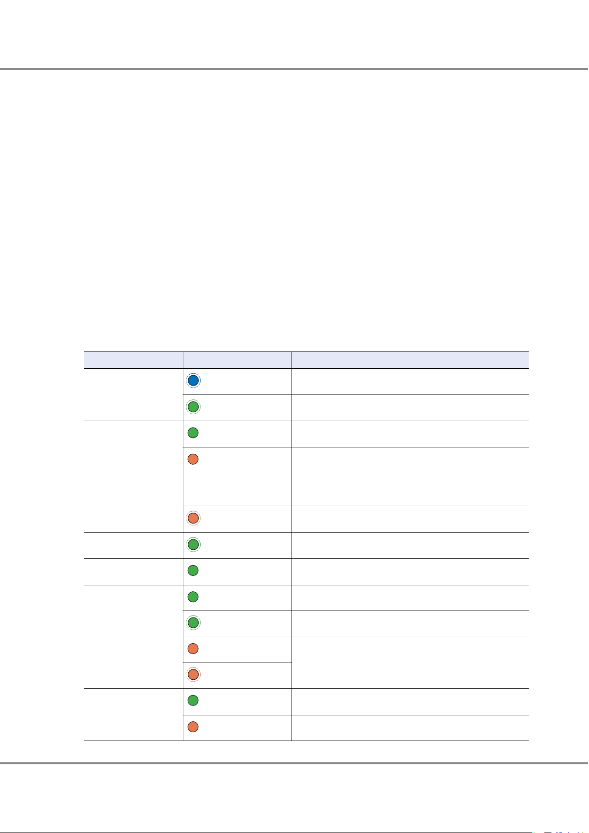
Table 3 Status and Meanings of Each LED (Controller)
LED name LED status Meaning
IDENTIFY/BBU FAULT
(blinks blue)
(amber)
As ordered via ETERNUS Web GUI or ETERNUS CLI, the installation
location of the controller is identified.
The battery is in error status.
DI (OUT) LINK/FAULT
LAN ACT
LAN LINK
READY/FAULT
LINK/FAULT
(green)
(amber)
(blinks amber)
(blinks green)
(green)
(green)
(blinks green)
(amber)
(blinks amber)
(green)
(amber)
The link between the DI (OUT) port and the destination port has
been established.
The link between the DI (OUT) port and the destination port is
•
in error status.
The ports to remove the cables between enclosures from are in-
•
dicated. This occurs while a drive enclosure is being added.
The ports to connect the cables are indicated. This occurs while a
drive enclosure is being added.
Data is being sent or received via the LAN port.
The link between the LAN port and the destination has been established.
The controller is in normal status.
An error has occurred during startup.
The controller is performing the initial setup after the power is
•
turned on.
The controller is in error status.
•
The link between the host interface port (FC or SAS) and the destination port has been established.
The host interface port (FC or SAS) is in error status.
FAULT
LINK
CA FAULT
MASTER
(green)
(amber)
(amber)
(green)
The link between the host interface port (iSCSI) and the destination port has been established.
The host interface port (iSCSI) is in error status.
The host interface is in error status.
The controller is set as a Master CM.
16
FUJITSU Storage ETERNUS DX60 S4, ETERNUS DX60 S3 Hybrid Storage Systems Operation Guide (Basic)
Copyright 2018 FUJITSU LIMITED
P3AM-9012-08ENZ0
Page 17

1234 5 6
1.
Component Names and LED Names
Controller Enclosures
■
Power Supply Units
The power supply unit transforms input AC power from a power socket to DC power and supplies power to each
component.
Each power supply unit contains fans.
Figure 11 shows the power supply unit. Table 4 shows the status and meanings of each LED.
Figure 11 Power Supply Unit (Controller Enclosure)
1.
POWER LED
2. FAULT LED
3. AC MISSING LED
4. FAN FAIL LED
5. PSU switch
This switch is used to turn on and off the AC power supply.
6. Inlet
This inlet is used to connect a power cord.
The LEDs turn on or blink to indicate the statuses that are listed below.
Table 4 Status and Meanings of Each LED (Power Supply Unit (Controller Enclosure))
LED name
POWER
FAULT
AC MISSING
FAN FAIL
LED status Meaning
(green)
(blinks green)
(amber)
(amber)
(amber)
AC power is supplied to the power supply unit.
AC power is supplied to the power supply unit, but DC power is
not supplied to the ETERNUS DX.
AC power is not supplied to the power supply unit.
AC power is not supplied to this power supply unit, but AC power
is supplied to the other power supply unit.
The power supply unit or the fan in the power supply unit is in error status.
ETERNUS DX60 S3 Components (Rear)
This section describes the controllers and the power supply units in the rear of the controller enclosure for the
ETERNUS DX60 S3.
■
Controllers
The controller contains a CPU, cache memory, System Capacitor Unit (SCU), host interfaces, drive interface (DI)
ports, and LAN ports. The controller controls all operations in the ETERNUS DX.
FUJITSU Storage ETERNUS DX60 S4, ETERNUS DX60 S3 Hybrid Storage Systems Operation Guide (Basic)
Copyright 2018 FUJITSU LIMITED
17
P3AM-9012-08ENZ0
Page 18

1234
5
1412 13
151415
16 20 21
SAS
FC
iSCSI 1Gbit/s
iSCSI 10Gbit/s
6
8
10711
9
17 17 17 17
1818
1919
8
9
18
19
18
19
1. Component Names and LED Names
Controller Enclosures
Controllers (FC, iSCSI 10Gbit/s, iSCSI 1Gbit/s, and SAS) are available for different types of host interfaces.
Figure 12 shows the controller. Table 5 shows the status and meanings of each LED.
Figure 12 Controllers
1. PWC port
This port is used to connect a power synchronization unit with an RS232C cable.
2. DI (OUT) port
This port is used to connect a controller enclosure to a drive enclosure with a mini SAS HD cable between enclo-
sures.
3. RMT (LAN) port
This port is used for connecting a LAN cable and used for the remote support function. This port uses an RJ-45
connector.
4. MNT (LAN) port
This port is used for connecting a LAN cable and used for operation management. This port uses an RJ-45 con-
nector.
5. Host interface (CA#0)
This interface is used for connecting a controller with a server.
6. Host interface port (FC port) (CA#0, Port#0)
This port is used for connecting a controller to a server with an FC cable. This port uses a Dual LC connector.
7. Host interface port (FC port) (CA#0, Port#1)
This port is used for connecting a controller to a server with an FC cable. This port uses a Dual LC connector.
8. Host interface port (iSCSI port) (CA#0, Port#0)
This port is used for connecting a LAN cable. This port uses an RJ-45 connector.
9. Host interface port (iSCSI port) (CA#0, Port#1)
This port is used for connecting a LAN cable. This port uses an RJ-45 connector.
18
FUJITSU Storage ETERNUS DX60 S4, ETERNUS DX60 S3 Hybrid Storage Systems Operation Guide (Basic)
Copyright 2018 FUJITSU LIMITED
P3AM-9012-08ENZ0
Page 19
1. Component Names and LED Names
Controller Enclosures
10. Host interface port (SAS port) (CA#0, Port#0)
This port is used for connecting an SAS cable. This port uses a miniSAS (SFF-8088) connector.
11. Host interface port (SAS port) (CA#0, Port#1)
This port is used for connecting an SAS cable. This port uses a miniSAS (SFF-8088) connector.
12. IDENTIFY/SCU READY LED
13. DI (OUT) LINK/FAULT LED
14. LAN ACT LED
15. LAN LINK LED
16. READY/FAULT LED
17. LINK/FAULT LED
18. FAULT LED
19. LINK LED
20. CA#0 FAULT LED
21. MASTER LED
The LEDs turn on or blink to indicate the statuses that are listed below.
Table 5 Status and Meanings of Each LED (Controller)
LED name
IDENTIFY/SCU READY
DI (OUT) LINK/FAULT
LAN ACT
LAN LINK
READY/FAULT
LED status Meaning
(blinks blue)
(blinks green)
(green)
(amber)
(blinks amber)
(blinks green)
(green)
(green)
(blinks green)
(amber)
(blinks amber)
As ordered via ETERNUS Web GUI or ETERNUS CLI, the installation
location of the controller is identified.
System Capacitor Unit (SCU) is charging.
The link between the DI (OUT) port and the destination port has
been established.
The link between the DI (OUT) port and the destination port is
•
in error status.
The ports to remove the mini SAS HD cables between enclo-
•
sures from are indicated. This occurs while a drive enclosure is
being added.
The ports to connect the cables are indicated. This occurs while a
drive enclosure is being added.
Data is being sent or received via the LAN port.
The link between the LAN port and the destination has been established.
The controller is in normal status.
An error has occurred during startup.
The controller is performing the initial setup after the power is
•
turned on.
The controller is in error status.
•
LINK/FAULT
(green)
(amber)
The link between the host interface port (FC or SAS) and the destination port has been established.
The host interface port (FC or SAS) is in error status.
19
FUJITSU Storage ETERNUS DX60 S4, ETERNUS DX60 S3 Hybrid Storage Systems Operation Guide (Basic)
Copyright 2018 FUJITSU LIMITED
P3AM-9012-08ENZ0
Page 20
1. Component Names and LED Names
Controller Enclosures
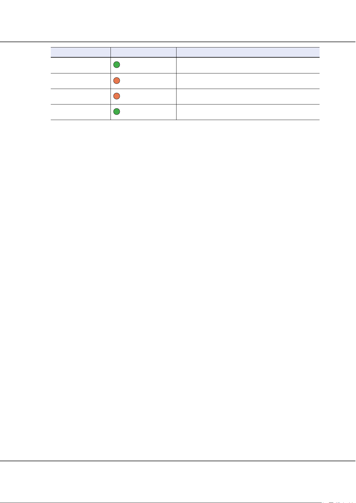
LED name LED status Meaning
FAULT
LINK
(green)
(amber)
The link between the host interface port (iSCSI) and the destination port has been established.
The host interface port (iSCSI) is in error status.
CA FAULT
MASTER
(amber)
The host interface is in error status.
The controller is set as a Master CM.
(green)
20
FUJITSU Storage ETERNUS DX60 S4, ETERNUS DX60 S3 Hybrid Storage Systems Operation Guide (Basic)
Copyright 2018 FUJITSU LIMITED
P3AM-9012-08ENZ0
Page 21

1234 5 6
1. Component Names and LED Names
Controller Enclosures
■
Power Supply Units
The power supply unit transforms input AC power from a power socket to DC power and supplies power to each
component.
Each power supply unit contains fans.
Figure 13 shows the power supply unit. Table 6 shows the status and meanings of each LED.
Figure 13 Power Supply Unit (Controller Enclosure)
1.
POWER LED
2. FAULT LED
3. AC MISSING LED
4. FAN FAIL LED
5. PSU switch
This switch is used to turn on and off the AC power supply.
6. Inlet
This inlet is used to connect a power cord.
The LEDs turn on or blink to indicate the statuses that are listed below.
Table 6 Status and Meanings of Each LED (Power Supply Unit (Controller Enclosure))
LED name
POWER
FAULT
AC MISSING
FAN FAIL
LED status Meaning
(green)
(blinks green)
(amber)
(amber)
(amber)
AC power is supplied to the power supply unit.
AC power is supplied to the power supply unit, but DC power is
not supplied to the ETERNUS DX.
AC power is not supplied to the power supply unit.
AC power is not supplied to this power supply unit, but AC power
is supplied to the other power supply unit.
The power supply unit or the fan in the power supply unit is in error status.
FUJITSU Storage ETERNUS DX60 S4, ETERNUS DX60 S3 Hybrid Storage Systems Operation Guide (Basic)
Copyright 2018 FUJITSU LIMITED
21
P3AM-9012-08ENZ0
Page 22

1
3 3
2
1
3 3
2
1. Component Names and LED Names
Drive Enclosures
Drive Enclosures
Drives and an operation panel are installed in the front of the drive enclosure. I/O modules and power supply
units are installed in the rear.
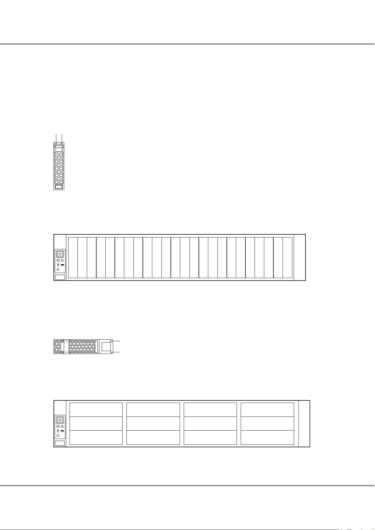
Front
This section provides the names of the components on the front of a drive enclosure.
■
2.5" Type
Figure 14 Front View of a 2.5" Type Drive Enclosure
1.
Operation panel
2. 2.5" drive
3. Flange cover
■
3.5" Type
Figure 15 Front View of a 3.5" Type Drive Enclosure
Operation panel
1.
2. 3.5" drive
3. Flange cover
22
FUJITSU Storage ETERNUS DX60 S4, ETERNUS DX60 S3 Hybrid Storage Systems Operation Guide (Basic)
Copyright 2018 FUJITSU LIMITED
P3AM-9012-08ENZ0
Page 23

12
34
12
34
1. Component Names and LED Names
Drive Enclosures
Rear
This section provides the names of the components on the rear of a drive enclosure.
When only one I/O module is installed
•
Figure 16 Rear View of a Drive Enclosure (When Only One I/O Module Is Installed)
1. I/O module (IOM#0)
2. Cover
Remove this when installing an additional I/O module (optional).
3. Power supply unit (PSU#0)
4. Power supply unit (PSU#1)
When two I/O modules are installed
•
Figure 17 Rear View of a Drive Enclosure (When Two I/O Modules Are Installed)
I/O module (IOM#0)
1.
2. I/O module (IOM#1)
3. Power supply unit (PSU#0)
4. Power supply unit (PSU#1)
23
FUJITSU Storage ETERNUS DX60 S4, ETERNUS DX60 S3 Hybrid Storage Systems Operation Guide (Basic)
Copyright 2018 FUJITSU LIMITED
P3AM-9012-08ENZ0
Page 24

2
1
3
4
1. Component Names and LED Names
Drive Enclosures
Components (Front)
This section describes the operation panel and the drives in the front of the drive enclosure.
■
Operation Panel
An operation panel has a DE-ID display and LEDs.
Figure 18 shows the operation panel. Table 7 shows the status and meanings of each LED.
Figure 18 Operation Panel (Drive Enclosure)
1.
DE-ID
The DE-ID (drive enclosure number) of the drive enclosure is displayed.
2. IDENTIFY LED
3. FAULT LED
4. POWER LED
The LEDs turn on or blink to indicate the statuses that are listed below.
Table 7 Status and Meanings of Each LED (Operation Panel (Drive Enclosure))
LED name
IDENTIFY
FAULT
POWER
LED status Meanings
(blinks blue)
(amber)
(green)
The installation location of the drive enclosure is identified according to the instruction that is issued from ETERNUS Web GUI or
ETERNUS CLI.
The drive enclosure is in error status.
DC power is supplied to the drive enclosure.
24
FUJITSU Storage ETERNUS DX60 S4, ETERNUS DX60 S3 Hybrid Storage Systems Operation Guide (Basic)
Copyright 2018 FUJITSU LIMITED
P3AM-9012-08ENZ0
Page 25

12
Slot#8
Slot#9
Slot#10
Slot#11
Slot#12
Slot#13
Slot#14
Slot#15
Slot#0
Slot#1
Slot#2
Slot#3
Slot#4
Slot#5
Slot#6
Slot#7
Slot#16
Slot#17
Slot#18
Slot#19
Slot#20
Slot#21
Slot#22
Slot#23
1
2
Slot#0
Slot#4
Slot#8
Slot#1
Slot#5
Slot#9
Slot#2
Slot#6
Slot#10
Slot#3
Slot#7
Slot#11
1.
Component Names and LED Names
Drive Enclosures
■
Drives
● 2.5" Drives
Figure 19 shows the 2.5" drive. Figure 20 shows the slot number of each 2.5" drive.
Table 8 shows the status and meanings of each LED.
Figure 19 2.5" Drives
1.
DRIVE READY LED
2. DRIVE FAULT LED
Figure 20 Drive Slot Numbers (2.5" Type Drive Enclosure)
● 3.5" Drives
Figure 21 shows the 3.5" drive. Figure 22 shows the slot number of each 3.5" drive.
Table 8 shows the status and meanings of each LED.
Figure 21 3.5" Drives
DRIVE READY LED
1.
2. DRIVE FAULT LED
Figure 22 Drive Slot Numbers (3.5" Type Drive Enclosure)
25
FUJITSU Storage ETERNUS DX60 S4, ETERNUS DX60 S3 Hybrid Storage Systems Operation Guide (Basic)
Copyright 2018 FUJITSU LIMITED
P3AM-9012-08ENZ0
Page 26
14
7
8
9
23 56
1. Component Names and LED Names
Drive Enclosures
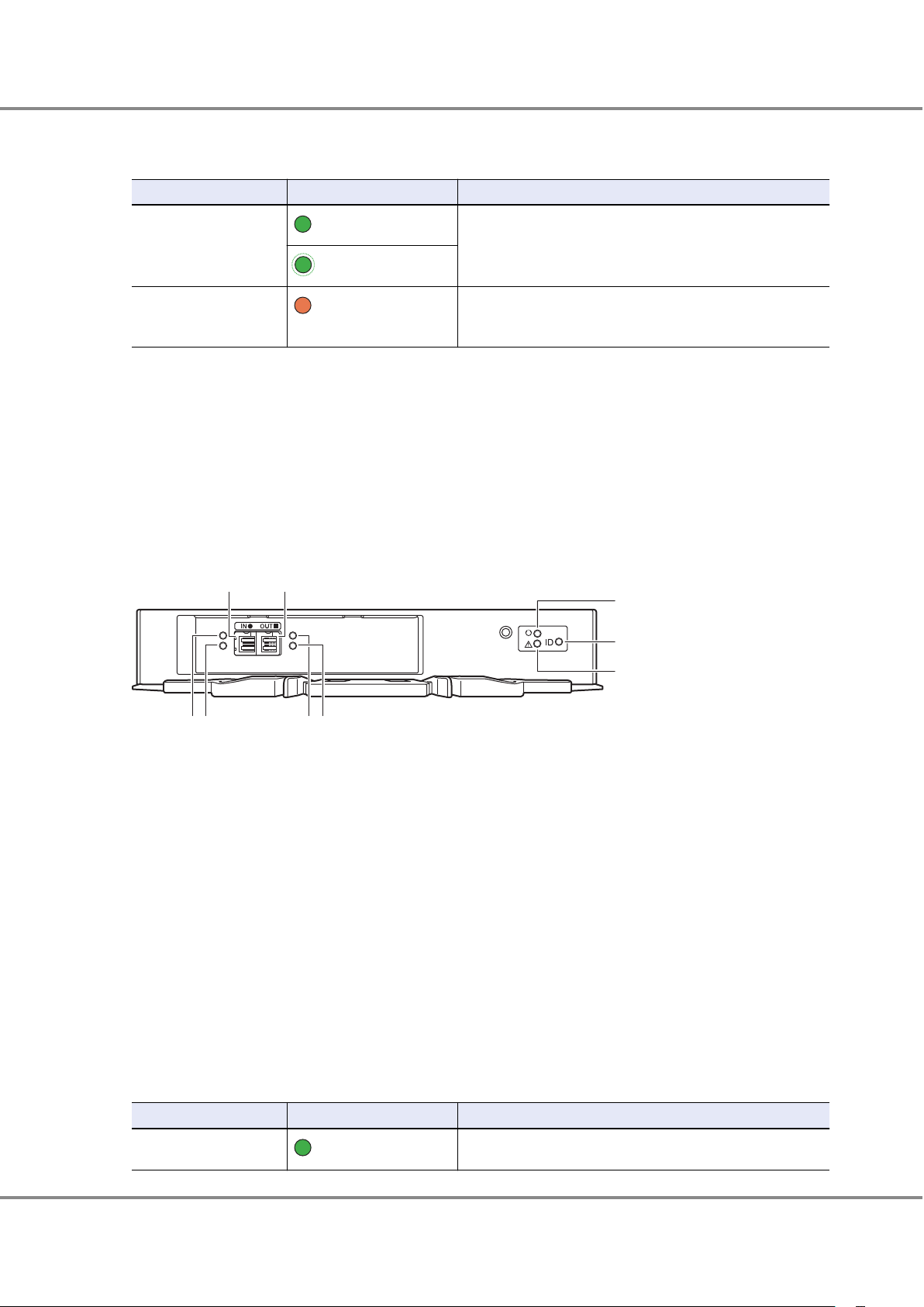
The LEDs turn on or blink to indicate the statuses that are listed below.
Table 8 Status and Meanings of Each LED (Drive (Drive Enclosure))
LED name LED status Meanings
DRIVE READY
(green)
The drive is in normal status.
(blinks green)
DRIVE FAULT
Components (Rear)
This section describes the I/O modules and the power supply units in the rear of the drive enclosure.
■
I/O Modules
The I/O module is a component that controls how the controller and the drives interact.
Figure 23 shows the I/O module. Table 9 shows the status and meanings of each LED.
Figure 23 I/O Module
(amber)
The drive is in error status.
•
The LED light up operation was performed from the ETERNUS
•
CLI command line in order to identify the drive location.
DI (IN) port
1.
This port is used to connect between enclosures.
2. DI (IN) LINK LED
3. DI (IN) FAULT LED
4. DI (OUT) port
This port is used to connect between enclosures.
5. DI (OUT) LINK LED
6. DI (OUT) FAULT LED
7. READY LED
8. IDENTIFY LED
9. FAULT LED
The LEDs turn on or blink to indicate the statuses that are listed below.
Table 9 Status and Meanings of Each LED (I/O Module)
LED name
DI (IN) LINK
LED status Meaning
(green)
The link between the DI (IN) port and the source port has been
established.
26
FUJITSU Storage ETERNUS DX60 S4, ETERNUS DX60 S3 Hybrid Storage Systems Operation Guide (Basic)
Copyright 2018 FUJITSU LIMITED
P3AM-9012-08ENZ0
Page 27
1. Component Names and LED Names
Drive Enclosures
LED name LED status Meaning
DI (IN) FAULT
DI (OUT) LINK
DI (OUT) FAULT
READY
(amber)
(blinks amber)
(green)
(amber)
(blinks amber)
(green)
The link between the DI (IN) port and the source port is in error
status.
The ports to connect the cables are indicated. This occurs while a
drive enclosure is being added.
The link between the DI (OUT) port and the destination port has
been established.
The link between the DI (OUT) port and the destination port is in
error status.
The ports to connect the cables are indicated. This occurs while a
drive enclosure is being added.
The I/O module is in normal status.
IDENTIFY
FAULT
(blinks blue)
(amber)
The installation location of the I/O module is identified according
to the instruction that is issued from ETERNUS Web GUI or ETERNUS CLI.
The I/O module is in error status.
27
FUJITSU Storage ETERNUS DX60 S4, ETERNUS DX60 S3 Hybrid Storage Systems Operation Guide (Basic)
Copyright 2018 FUJITSU LIMITED
P3AM-9012-08ENZ0
Page 28

1234 5 6
1. Component Names and LED Names
Drive Enclosures
■
Power Supply Units
The power supply unit transforms input AC power from a power socket to DC power and supplies power to each
component.
Each power supply unit contains fans.
Figure 24 shows the power supply unit. Table 10 shows the status and meanings of each LED.
Figure 24 Power Supply Unit (Drive Enclosure)
1.
POWER LED
2. FAULT LED
3. AC MISSING LED
4. FAN FAIL LED
5. PSU switch
This switch is used to turn on and off the AC power supply.
6. Inlet
This inlet is used to connect a power cord.
The states of LEDs are listed below.
Table 10 Status and Meanings of Each LED (Power Supply Unit (Drive Enclosure))
LED name
POWER
FAULT
AC MISSING
FAN FAIL
LED status Meaning
(green)
(amber)
(amber)
(amber)
AC power is supplied to the power supply unit.
AC power is not supplied to the power supply unit.
AC power is not supplied to this power supply unit, but AC power
is supplied to the other power supply unit.
The power supply unit or the fan in the power supply unit is in error status.
FUJITSU Storage ETERNUS DX60 S4, ETERNUS DX60 S3 Hybrid Storage Systems Operation Guide (Basic)
Copyright 2018 FUJITSU LIMITED
28
P3AM-9012-08ENZ0
Page 29

3
2
1
3
2
1
1. Component Names and LED Names
Power Distribution Units (for Regions other than the EMEIA, Central American, and Caribbean Regions)
Power Distribution Units (for Regions other than the EMEIA, Central American, and Caribbean Regions)
There are two sizes for power distribution units: 1U and 2U.
Power Distribution Units (1U)
The 1U power distribution unit has four outlets and two inlets.
■
Power Distribution Unit (AC200-240V, 1U, 4 Outlets)
For power distribution units (AC200-240V, 1U, 4 Outlets), there are two different types of exteriors.
Figure 25 Power Distribution Unit (AC200-240V, 1U, 4 Outlets)
1.
Main line switch
This turns on and off the power distribution unit.
2. Outlet (OUTPUT)
This is a socket (IEC60320 C13) for outgoing power supply. This socket is used to connect a power cord (AC out-
put cable).
3. Inlet (INPUT)
This is a socket (IEC60320 C14) for incoming power supply. This socket is used to connect a power cord (AC input
cable).
Figure 26 Power Distribution Unit (AC200-240V, 1U, 4 Outlets)
Main line switch
1.
This turns on and off the power distribution unit.
2. Outlet (OUTPUT)
This is a socket (IEC60320 C13) for outgoing power supply. This socket is used to connect a power cord (AC out-
put cable).
3. Inlet (INPUT)
This is a socket (IEC60320 C14) for incoming power supply. This socket is used to connect a power cord (AC input
cable).
29
FUJITSU Storage ETERNUS DX60 S4, ETERNUS DX60 S3 Hybrid Storage Systems Operation Guide (Basic)
Copyright 2018 FUJITSU LIMITED
P3AM-9012-08ENZ0
Page 30

2
1
2
1
1. Component Names and LED Names
Power Distribution Units (for Regions other than the EMEIA, Central American, and Caribbean Regions)
Power Distribution Units (2U)
2U power distribution units are available in two types: a 12 outlet type and a 16 outlet type.
■
Power Distribution Unit (AC200-240V, 2U, 12 Outlets)
There are 12 outlets.
Figure 27 Power Distribution Unit (AC200-240V, 2U, 12 Outlets)
1.
Main line switch
This turns on and off the power distribution unit.
2. Outlet (OUTPUT)
This is a socket (IEC60320 C13) for outgoing power supply. This socket is used to connect a power cord (AC out-
put cable).
■
Power Distribution Unit (AC200-240V, 2U, 16 Outlets)
For power distribution units (AC200-240V, 2U, 16 Outlets), there are two different types of exteriors.
There are 16 outlets.
Figure 28 Power Distribution Unit (AC200-240V, 2U, 16 Outlets)
Main line switch
1.
This turns on and off the power distribution unit.
30
FUJITSU Storage ETERNUS DX60 S4, ETERNUS DX60 S3 Hybrid Storage Systems Operation Guide (Basic)
Copyright 2018 FUJITSU LIMITED
P3AM-9012-08ENZ0
Page 31

2
1
1
1. Component Names and LED Names
Power Distribution Units (for Regions other than the EMEIA, Central American, and Caribbean Regions)
2. Outlet (OUTPUT)
This is a socket (IEC60320 C13) for outgoing power supply. This socket is used to connect a power cord (AC out-
put cable).
Figure 29 Power Distribution Unit (AC200-240V, 2U, 16 Outlets)
1. Main line switch
This turns on and off the power distribution unit.
2. Outlet (OUTPUT)
This is a socket (IEC60320 C13) for outgoing power supply. This socket is used to connect a power cord (AC out-
put cable).
31
FUJITSU Storage ETERNUS DX60 S4, ETERNUS DX60 S3 Hybrid Storage Systems Operation Guide (Basic)
Copyright 2018 FUJITSU LIMITED
P3AM-9012-08ENZ0
Page 32

2. Basic Operation
Main line switch
Main line switch
This chapter explains how to turn on and off the ETERNUS DX and how to operate the FUNCTION button on the
controller enclosure.
Powering On and Off
This section explains how to turn on and off the ETERNUS DX.
Switching On and Off the Main Line Switch on the Power Distribution Unit (for Regions other than the EMEIA, Central American, and Caribbean Regions)
This section explains how to switch the main line switch of the power distribution unit to ON and OFF.
For power distribution units, there are two different types of exteriors.
■
To Switch to ON
Turn the main line switch of the power distribution unit to the ON position (marked "|").
Make sure all of the main line switches are in the ON position.
● For 1U
Figure 30 ON Position (Marked "|") of the Main Line Switches on a 1U Power Distribution Unit
Figure 31 ON Position of the Main Line Switches on a 1U Power Distribution Unit
32
FUJITSU Storage ETERNUS DX60 S4, ETERNUS DX60 S3 Hybrid Storage Systems Operation Guide (Basic)
Copyright 2018 FUJITSU LIMITED
P3AM-9012-08ENZ0
Page 33

Main line switch
Main line switch
2.
Basic Operation
Powering On and Off
● For 2U
Figure 32 ON Position (Marked "|") of the Main Line Switches on a 2U Power Distribution Unit
Figure 33 ON Position of the Main Line Switches on a 2U Power Distribution Unit
■
To Switch to OFF
Turn the main line switch of the power distribution unit to the OFF position (marked "¡").
This does not need to be turned off for normal operation. If the ETERNUS DX must be turned off, such as before any inspections of power supply devices are performed, turn off the ETERNUS DX by using the procedure
described in "Powering Off" (page 39), turn all the PSU switches of the power supply unit to the OFF position, and turn the main line switch to the OFF position.
33
FUJITSU Storage ETERNUS DX60 S4, ETERNUS DX60 S3 Hybrid Storage Systems Operation Guide (Basic)
Copyright 2018 FUJITSU LIMITED
P3AM-9012-08ENZ0
Page 34

Main line switch
Main line switch
2. Basic Operation
Powering On and Off
● For 1U
Figure 34 OFF Position (Marked "¡") of the Main Line Switches on a 1U Power Distribution Unit
Figure 35 OFF Position of the Main Line Switches on a 1U Power Distribution Unit
34
FUJITSU Storage ETERNUS DX60 S4, ETERNUS DX60 S3 Hybrid Storage Systems Operation Guide (Basic)
Copyright 2018 FUJITSU LIMITED
P3AM-9012-08ENZ0
Page 35

Main line switch
Main line switch
2.
Basic Operation
Powering On and Off
● For 2U
Figure 36 OFF Position (Marked "¡") of the Main Line Switches on a 2U Power Distribution Unit
Figure 37 OFF Position of the Main Line Switches on a 2U Power Distribution Unit
When turning the main line switch to ON (marked "|") right after turning the main line switch to OFF (marked
"¡"), turn it back to ON (marked "|") after the POWER LED of the power supply unit has turned off completely.
35
FUJITSU Storage ETERNUS DX60 S4, ETERNUS DX60 S3 Hybrid Storage Systems Operation Guide (Basic)
Copyright 2018 FUJITSU LIMITED
P3AM-9012-08ENZ0
Page 36

Power supply unit (PSU#0) Power supply unit (PSU#1)
Drive enclosure
Controller enclosure
Power supply unit (PSU#1)Power supply unit (PSU#0)
POWER
LED
2.
Basic Operation
Powering On and Off
Switching On and Off the PSU Switch on the Power Supply Unit
This section explains how to move the PSU switch of the power supply unit of the controller enclosure and drive
enclosures to the ON and OFF positions in each enclosure.
■
To Switch to ON
Turn the PSU switch of the power supply unit to the ON position (marked "|").
Make sure all of the PSU switches are in the ON position.
Figure 38 ON Position (Marked "|") of the PSU Switch on a Power Supply Unit
AC power is supplied to an enclosure.
For the controller enclosure, the POWER LED on the power supply unit blinks green.
•
For the drive enclosure, the POWER LED on the power supply unit emits green lights and the fan revolves at
•
high speed for 30 seconds.
FUJITSU Storage ETERNUS DX60 S4, ETERNUS DX60 S3 Hybrid Storage Systems Operation Guide (Basic)
36
Copyright 2018 FUJITSU LIMITED
P3AM-9012-08ENZ0
Page 37

Power supply unit (PSU#0) Power supply unit (PSU#1)
2.
Basic Operation
Powering On and Off
■
To Switch to OFF
Turn the PSU switch of the power supply unit to the OFF position (marked "¡").
This does not need to be turned off for normal operation.
Figure 39 OFF Position (Marked "¡") of the PSU Switch of a Power Supply Unit
Check that the POWER LED of the power supply unit is off.
FUJITSU Storage ETERNUS DX60 S4, ETERNUS DX60 S3 Hybrid Storage Systems Operation Guide (Basic)
37
Copyright 2018 FUJITSU LIMITED
P3AM-9012-08ENZ0
Page 38

2.
Basic Operation
Powering On and Off
Powering On
This section explains how to turn on the ETERNUS DX.
To turn on the ETERNUS DX, perform the following procedure.
Via the power switch
•
Press the Power switch to turn on the ETERNUS DX.
The following methods can be used to turn the power on by linking with the server.
Power Synchronized Unit
•
Use the power synchronized unit to turn on the ETERNUS DX.
Wake On LAN
•
Use the Wake On LAN function to turn on the power.
Before turning on the ETERNUS DX, make sure that the main line switches of the power distribution units and
the PSU switches on the power supply units of the ETERNUS DX are "ON". Do not turn the main line switches of
the power distribution units and the PSU switches on the ETERNUS DX to the OFF position.
After turning the power on, it takes approximately five minutes for the ETERNUS DX to reach the READY
•
state (the READY LED turns on). If an error is detected in a component during the initial power-on diagnostics, it may take up to 10 minutes for the ETERNUS DX to reach the READY state. This should be taken into
consideration for scheduled operations.
Before turning the server on, check that the ETERNUS DX and the network devices that connect the ETER-
•
NUS DX and the server are all in READY status.
If the server is turned on while any of these devices are not in READY status, the server may not be able to
recognize the ETERNUS DX.
To turn on the ETERNUS DX by linking with the server, the server must wait until the ETERNUS DX is in the
•
READY state.
If the Auto Power function is enabled via ETERNUS Web GUI or ETERNUS CLI, the ETERNUS DX is automatical-
•
ly turned on when power is supplied to the ETERNUS DX.
If the Power Resume function is enabled via ETERNUS Web GUI or ETERNUS CLI, the ETERNUS DX is automat-
•
ically turned on after the power is restored.
After power-off, wait for about one minute before turning power on again.
•
If the ETERNUS DX is not turned off normally due to problems such as a power failure, it takes approximate-
•
ly five minutes (max.) longer to reach the READY state the next time the ETERNUS DX is turned on.
This section explains how to use the Power switch to turn on the ETERNUS DX.
For other procedures, refer to the related manuals.
38
FUJITSU Storage ETERNUS DX60 S4, ETERNUS DX60 S3 Hybrid Storage Systems Operation Guide (Basic)
Copyright 2018 FUJITSU LIMITED
P3AM-9012-08ENZ0
Page 39

Power switch
2.
Basic Operation
Powering On and Off
1 Press the Power switch of the controller enclosure.
2 After approximately five minutes, check that the READY LED is lit up.
The POWER LED is turned on.
Powering Off
This section explains how to turn off the ETERNUS DX.
To turn off the ETERNUS DX, perform one of the procedures below.
Via power switch
•
Press the Power switch to turn off the ETERNUS DX.
Via ETERNUS Web GUI or ETERNUS CLI
•
Use ETERNUS Web GUI or ETERNUS CLI to turn off the ETERNUS DX.
The following methods can be used to turn off the power by linking with the server.
Via the power synchronized unit
•
Use the power synchronized unit to turn off the ETERNUS DX.
39
FUJITSU Storage ETERNUS DX60 S4, ETERNUS DX60 S3 Hybrid Storage Systems Operation Guide (Basic)
Copyright 2018 FUJITSU LIMITED
P3AM-9012-08ENZ0
Page 40

Power switch
2.
Basic Operation
Powering On and Off
•
•
•
•
•
This section explains how to use the Power switch to turn off the ETERNUS DX.
For other procedures, refer to the related manuals.
When the ETERNUS DX is turned off, the power shuts off after the write data in the cache memory is written
back to the drives. As a result, it may take approximately five minutes or up to 10 minutes maximum for
the power supply to be completely turned off.
Do not turn off the power of the ETERNUS DX and the network devices that connect the ETERNUS DX to a
server while the server is operating. This may result in the loss of data or prevent data from being saved in
the ETERNUS DX.
When using a power synchronized unit for power control, turn off the power of the ETERNUS DX via the power synchronized unit. When a power synchronized unit is connected, the power of the ETERNUS DX is automatically turned on because the power synchronization function is activated.
To turn off the ETERNUS DX60 S4, use the Power switch, a power synchronized unit, ETERNUS Web GUI, or
ETERNUS CLI. If any other method is used to turn off the ETERNUS DX, the replacement cycle for the battery
is shortened significantly because the battery continues to charge and discharge.
After power-off, wait for about one minute before turning power on again.
1 Press and hold the Power switch of the controller enclosure for four seconds or more.
The READY LED is turned off.
Press the Power switch only once. If the Power switch is pressed again between the time of the READY
LED turning off and the POWER LED turning off, the ETERNUS DX power may turn on.
2
The power of the ETERNUS DX is disconnected.
When the power is disconnected, the POWER LED is turned off.
40
FUJITSU Storage ETERNUS DX60 S4, ETERNUS DX60 S3 Hybrid Storage Systems Operation Guide (Basic)
Copyright 2018 FUJITSU LIMITED
P3AM-9012-08ENZ0
Page 41

2.
Basic Operation
Using the FUNCTION Button
Using the FUNCTION Button
This section explains how to use the FUNCTION button of the controller enclosure.
The following settings can be performed by using the FUNCTION button:
Switching the Master CM to the other controller
•
For the two controllers in the ETERNUS DX, the controller through which the ETERNUS DX is set up and operated is called the "Master CM", while the other controller is called the "Slave CM". The single-controller type
only has a "Master CM" controller.
Restoring the factory default settings (network environment settings and firewall settings) of the LAN ports
•
Restoring the factory default user settings (user account, role, and RADIUS settings)
•
The following procedure explains how to use the FUNCTION button.
1 Remove the flange cover of the controller enclosure.
2 Change the status of the ETERNUS DX to maintenance status.
Use the pin to push down the FUNCTION button for three seconds.
The ETERNUS DX is in maintenance status when the MAINTENANCE LED is green.
41
FUJITSU Storage ETERNUS DX60 S4, ETERNUS DX60 S3 Hybrid Storage Systems Operation Guide (Basic)
Copyright 2018 FUJITSU LIMITED
P3AM-9012-08ENZ0
Page 42

2.
Basic Operation
Using the FUNCTION Button
3 Use the FUNCTION button to change settings.
• Switching the Master CM to the other controller when two controllers are installed
Use the pin to push down the FUNCTION button twice within three seconds.
The MASTER LED for the controller that is set as the Master CM is green.
• Restoring the factory default settings of the LAN ports
Use the pin to push down the FUNCTION button three times within three seconds.
After the default settings of the LAN ports are restored, the MAINTENANCE LED blinks green a few times a
second for several seconds.
• Restoring the factory default user settings
(1) Remove all the LAN cables from the LAN ports (MNT ports and RMT ports) of all the controllers.
(2) Use the pin to push down the FUNCTION button five times within three seconds.
After the default user settings are restored, the MAINTENANCE LED blinks green approximately every second for several seconds.
4 Release maintenance status.
Use the pin to push down the FUNCTION button for three seconds.
The MAINTENANCE LED turns off, which indicates that the ETERNUS DX is no longer in maintenance status.
5 Attach the flange cover.
42
FUJITSU Storage ETERNUS DX60 S4, ETERNUS DX60 S3 Hybrid Storage Systems Operation Guide (Basic)
Copyright 2018 FUJITSU LIMITED
P3AM-9012-08ENZ0
Page 43

3. Storage System Monitoring
This chapter describes the status monitoring of the ETERNUS DX.
Checking LED Status
The status of the ETERNUS DX can be checked by the LEDs.
If the FAULT LED in the operation panel is amber, contact your maintenance engineer.
Displaying Status via ETERNUS Web GUI
The status of the ETERNUS DX and the usage status of RAID groups, TPPs, and SDPs can be checked in the Overview screen of ETERNUS Web GUI.
Figure 40 ETERNUS Web GUI Screen
Table 11 shows the general status.
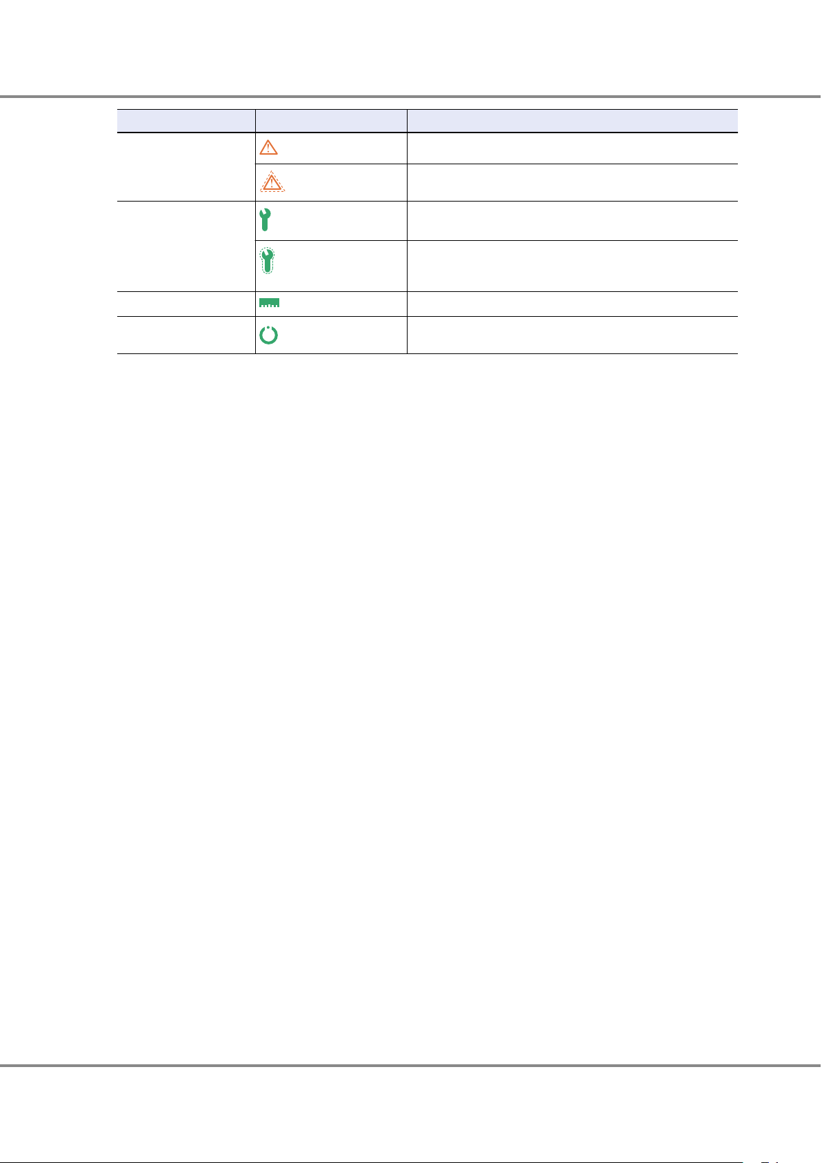
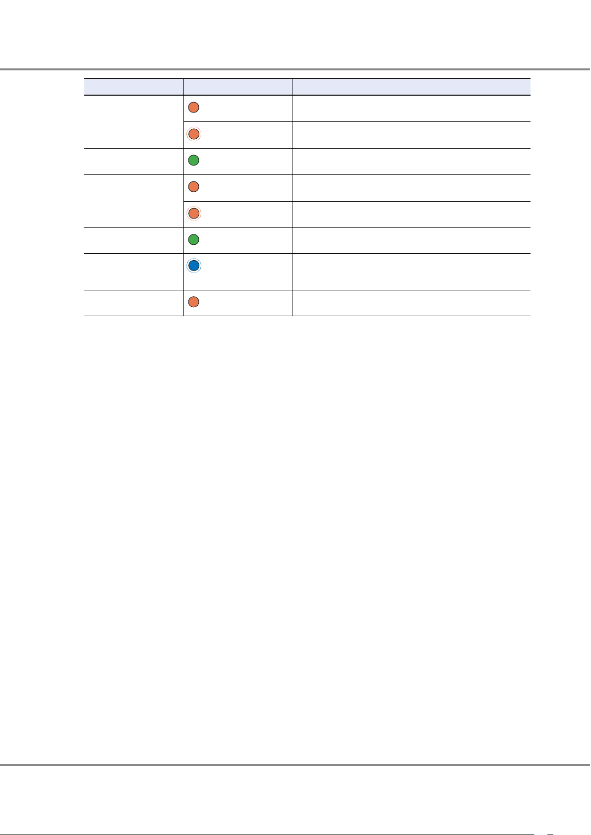
Status of the ETERNUS DX is monitored periodically, and the result is displayed as a general status icon with
character strings.
Table 11 General Status of ETERNUS Web GUI
Status
(green)
(red)
Description
The ETERNUS DX is in a normal state.
An abnormality is detected at a power-off, and I/O access from the server
cannot be received.
43
FUJITSU Storage ETERNUS DX60 S4, ETERNUS DX60 S3 Hybrid Storage Systems Operation Guide (Basic)
Copyright 2018 FUJITSU LIMITED
P3AM-9012-08ENZ0
Page 44

3.
Storage System Monitoring
Displaying Status via ETERNUS CLI
Status Description
The ETERNUS DX is in error state.
(red)
The ETERNUS DX is under maintenance.
(orange)
The ETERNUS DX is in warning state.
(yellow)
For details, refer to "Configuration Guide (Web GUI)".
Displaying Status via ETERNUS CLI
The status of the ETERNUS DX and the usage status of RAID groups, TPPs, and SDPs can be checked by sending
the status display command via ETERNUS CLI.
CLI> show status
Summary Status [Normal]
CLI> show status
Summary Status [Error]
CLI> show status
Summary Status [Warning]
The general status of the ETERNUS DX indicates whether an error status component or a warning status component exists in the storage system.
Table 12 General Status of ETERNUS CLI
Status
Empty An undefined or uninstalled component exists in the ETERNUS DX.
Normal The ETERNUS DX is in a normal state.
Pinned Data Pinned data exists in the ETERNUS DX.
Unused An undefined component is installed in the ETERNUS DX.
Warning The ETERNUS DX contains a component that requires preventive maintenance.
Maintenance The ETERNUS DX is under maintenance.
Error An error has occurred in a component that is installed in the ETERNUS DX.
Loop Down The ETERNUS DX is in the BackEnd Down state.
Not Ready An abnormality is detected and access from the host cannot be received.
Subsystem Down The ETERNUS DX cannot be used.
Change Assigned CM CM hot expansion recovery is required.
Event Notification
Description
By setting event notification, if an error (event) occurs in the ETERNUS DX, the event information is notified.
The methods that can be used to notify an event are "e-mail", "SNMP Trap", "Syslog", "remote support", and "host
sense".
For the procedure on setting event notification, refer to "Configuration Guide (Basic)".
44
FUJITSU Storage ETERNUS DX60 S4, ETERNUS DX60 S3 Hybrid Storage Systems Operation Guide (Basic)
Copyright 2018 FUJITSU LIMITED
P3AM-9012-08ENZ0
Page 45

SNMP managerMail server Syslog server
Remote
support
center
REMCS/AIS Connect
Host sense
Server (host)
syslog
SNMP Trap
E-mail
ETERNUS DX
3.
Storage System Monitoring
Audit Log
■
E-mail
When an event occurs in the ETERNUS DX, an e-mail is sent to the specified e-mail address.
For more details on notified event information, refer to "Message List".
■
SNMP Trap
When an event occurs in the ETERNUS DX, an SNMP Trap is sent to the SNMP Manager (monitoring server).
For more details on event information notified by SNMP Trap, refer to "Message List".
■
Syslog
When an event occurs in the ETERNUS DX, the event log can be sent to the external server (Syslog server).
For the notified Syslog messages, refer to "Message List".
■
Remote Support
The information for errors that occur in the ETERNUS DX is notified to the remote support center.
■
Host Sense
When an event occurs in the ETERNUS DX, host senses (sense codes) are sent to the server. For details on sense
codes, refer to "Message List".
Figure 41 Event Notification
Audit Log
By setting audit log, audit trail logs (hereinafter referred to as "audit log") that record performed operations by
using the ETERNUS DX and the system actions that are associated with these operations can be sent to the Syslog server.
45
FUJITSU Storage ETERNUS DX60 S4, ETERNUS DX60 S3 Hybrid Storage Systems Operation Guide (Basic)
Copyright 2018 FUJITSU LIMITED
P3AM-9012-08ENZ0
Page 46

System administrator
Login
Logout
Setting change
↓
↓
Device name
User/role
Process time
Process details
Process result
etc.
Audit log
ETERNUS DX
Syslog server
3. Storage System Monitoring
Audit Log
For the procedure on setting audit logs, refer to "Configuration Guide (Basic)". For log information, refer to "Message List".
Figure 42 Audit Log
FUJITSU Storage ETERNUS DX60 S4, ETERNUS DX60 S3 Hybrid Storage Systems Operation Guide (Basic)
46
Copyright 2018 FUJITSU LIMITED
P3AM-9012-08ENZ0
Page 47

4. Component Expansion/Function Enhancement
Do Not
Do
For the ETERNUS DX, customers can expand (add) the following optional products.
Drives
•
Drive enclosures
•
This chapter explains the handling instructions and the installation procedures for these optional products.
Make sure to read "Safety Precautions" before performing any of these procedures.
When adding servers to be connected, refer to "Adding Servers" (page 69).
Installing Additional Drives
Drives can be installed while the ETERNUS DX is running without affecting the system.
This section explains how to install drives in the ETERNUS DX.
Do not uninstall or move a drive that is already installed.
•
Contact your sales representative or maintenance engineer if drives that are installed
by default need to be uninstalled or moved to another slot.
Installable Drives
For installable drives, refer to "Product List".
Drive Handling Instructions
■
About Condensation
When moving a drive from a cold place, such as an unconditioned store house in win-
•
ter, to a warmer place such as an air-conditioned room, the severe temperature
change may result in condensation forming.
To avoid this, allow the packed drive sufficient time in the warmer place (one hour for
each 15°C of temperature difference) to adapt to the new temperature.
47
FUJITSU Storage ETERNUS DX60 S4, ETERNUS DX60 S3 Hybrid Storage Systems Operation Guide (Basic)
Copyright 2018 FUJITSU LIMITED
P3AM-9012-08ENZ0
Page 48

Do Not
Do
Do Not
4.
Component Expansion/Function Enhancement
Installing Additional Drives
■
About Static Electricity
Do not touch the surface of the board of the drives.
•
When handling drives, wear a wrist strap or touch a metal part to discharge the hu-
•
man body's natural static electricity. Failure to discharge static electricity may cause
failure in the ETERNUS DX.
Leave the drive in its package until ready to install it.
•
■
About Shock
Do not lay the drives directly on a desk or similar hard surface. Always use a rubber
•
mat or other soft material to cushion the drives against physical shocks.
Do not stack drives or stand drives on end.
•
Do not apply external force to the interface connectors.
•
Do not knock or drop the drives on hard objects.
•
Additional Drive Installation Procedure
This section explains how to install optional drives in the ETERNUS DX.
Drives can be installed in any slots.
48
FUJITSU Storage ETERNUS DX60 S4, ETERNUS DX60 S3 Hybrid Storage Systems Operation Guide (Basic)
Copyright 2018 FUJITSU LIMITED
P3AM-9012-08ENZ0
Page 49

Do
Do Not
4. Component Expansion/Function Enhancement
Installing Additional Drives
If components are installed in a way other as described in this section, damage and/or
•
device failure or electrical shock may occur.
Do not install drives that are for use in other devices.
•
49
FUJITSU Storage ETERNUS DX60 S4, ETERNUS DX60 S3 Hybrid Storage Systems Operation Guide (Basic)
Copyright 2018 FUJITSU LIMITED
P3AM-9012-08ENZ0
Page 50

Tab
Dummy drive unit
Catch
Lock lever
4.
Component Expansion/Function Enhancement
Installing Additional Drives
■
For 2.5" Drives
1 In the [Storage] screen of [Component] on the ETERNUS Web GUI screen, check that all components of the
ETERNUS DX are in normal status.
2 Wear a wrist strap or touch a metal part to discharge the human body's natural static electricity.
3 Remove the dummy drive unit from the slot in which the drive is to be installed.
Push into the tab of the dummy drive unit and pull it straight out of the drive slot.
Keep the removed dummy drive units in a safe place where they will not be lost.
4 Install the new drive.
(1) Press the catch on the drive lock lever to unlock it.
50
FUJITSU Storage ETERNUS DX60 S4, ETERNUS DX60 S3 Hybrid Storage Systems Operation Guide (Basic)
Copyright 2018 FUJITSU LIMITED
P3AM-9012-08ENZ0
Page 51

Do
Lock lever
4.
Component Expansion/Function Enhancement
Installing Additional Drives
(2) Insert the drive all the way into the slot, making sure that it is firmly seated and that the lock lever is
still left open.
• Hold the drive with both hands to protect against jarring.
(3) Swing the lock lever in the direction of the arrow, until the lock clicks shut.
(4) Check that the newly installed drive's DRIVE READY LED lights up green.
5 To install more additional drives, repeat Step 3 and Step 4.
6 If a wrist strap is used, remove the wrist strap.
7 In the [Drives] screen of [Component] on the ETERNUS Web GUI screen, check that the added drives have
been recognized.
8 Set up RAID groups, volumes, hot spares, and host affinity settings, as required.
51
FUJITSU Storage ETERNUS DX60 S4, ETERNUS DX60 S3 Hybrid Storage Systems Operation Guide (Basic)
Copyright 2018 FUJITSU LIMITED
P3AM-9012-08ENZ0
Page 52

Dummy drive unit
Tab
Catch
Lock lever
4.
Component Expansion/Function Enhancement
Installing Additional Drives
■
For 3.5" Drives
1 In the [Storage] screen of [Component] on the ETERNUS Web GUI screen, check that all components of the
ETERNUS DX are in normal status.
2 Wear a wrist strap or touch a metal part to discharge the human body's natural static electricity.
3 Remove the dummy drive unit from the slot in which the drive is to be installed.
Push into the tab of the dummy drive unit and pull it straight out of the drive slot.
Keep the removed dummy drive units in a safe place where they will not be lost.
4 Install the new drive.
(1) Press the catch on the drive lock lever to unlock it.
(2) Insert the drive all the way into the slot, making sure that it is firmly seated and that the lock lever is
still left open.
52
FUJITSU Storage ETERNUS DX60 S4, ETERNUS DX60 S3 Hybrid Storage Systems Operation Guide (Basic)
Copyright 2018 FUJITSU LIMITED
P3AM-9012-08ENZ0
Page 53

Do
Lock lever
4.
Component Expansion/Function Enhancement
Installing Additional Drives
(3) Swing the lock lever in the direction of the arrow, until the lock clicks shut.
(4) Check that the newly installed drive's DRIVE READY LED lights up green.
• Hold the drive with both hands to protect against jarring.
5 To install more additional drives, repeat Step 3 and Step 4.
6 If a wrist strap is used, remove the wrist strap.
7 In the [Drives] screen of [Component] on the ETERNUS Web GUI screen, check that the added drives have
been recognized.
8 Set up RAID groups, volumes, hot spares, and host affinity settings, as required.
53
FUJITSU Storage ETERNUS DX60 S4, ETERNUS DX60 S3 Hybrid Storage Systems Operation Guide (Basic)
Copyright 2018 FUJITSU LIMITED
P3AM-9012-08ENZ0
Page 54

Do Not
Do
Do
4.
Component Expansion/Function Enhancement
Installing Additional Drive Enclosures
Installing Additional Drive Enclosures
Drive enclosures can be installed while the ETERNUS DX is running without affecting the system.
This section explains how to install drive enclosures in the ETERNUS DX.
Do not uninstall or move a drive enclosure that is already installed.
•
Contact your sales representative or maintenance engineer if a drive enclosure needs
to be uninstalled or moved.
When installing the ETERNUS DX, secure the rack to the floor to prevent the rack from
•
moving out of place or from toppling over. For details on the rack installation requirements, refer to "Site Planning Guide".
Installable Drive Enclosures
For installable drive enclosures, refer to "Product List".
Drive Enclosure Handling Instructions
■
About Condensation
When moving a drive enclosure from a cold place, such as an unconditioned store
•
house in winter, to a warmer place such as an air-conditioned room, the severe temperature change may result in condensation forming.
To avoid this, allow the packed drive enclosure sufficient time in the warmer place
(one hour for each 15°C of temperature difference) to adapt to the new temperature.
54
FUJITSU Storage ETERNUS DX60 S4, ETERNUS DX60 S3 Hybrid Storage Systems Operation Guide (Basic)
Copyright 2018 FUJITSU LIMITED
P3AM-9012-08ENZ0
Page 55

Do
Do Not
4.
Component Expansion/Function Enhancement
Installing Additional Drive Enclosures
■
About Static Electricity
■
About Shock
When handling drive enclosures, wear a wrist strap or touch a metal part to discharge
•
the human body's natural static electricity. Failure to discharge static electricity may
cause failure in the ETERNUS DX.
Do not handle the drive enclosure roughly or subject it to physical shocks when laying
•
it down.
Do not stack the drive enclosures.
•
Do not knock or drop the drive enclosure on hard objects.
•
55
FUJITSU Storage ETERNUS DX60 S4, ETERNUS DX60 S3 Hybrid Storage Systems Operation Guide (Basic)
Copyright 2018 FUJITSU LIMITED
P3AM-9012-08ENZ0
Page 56

Do
Tab
4.
Component Expansion/Function Enhancement
Installing Additional Drive Enclosures
Additional Drive Enclosure Installation Procedure
This section explains how to install additional drive enclosures in the ETERNUS DX.
If components are installed in a way other than as described in this section, damage
•
and/or device failure or electrical shock may occur.
Do not install the drive enclosure in the rack with cables, such as power cords, connec-
•
ted.
Do not knock the other devices installed in the rack when installing drive enclosures.
•
When connecting the mini SAS HD cable between enclosures, check the direction of the connector (the tab
must be pointed downward) and firmly insert all the way in.
To disconnect the mini SAS HD cables between enclosures, hold the tab and then pull out the connector.
56
FUJITSU Storage ETERNUS DX60 S4, ETERNUS DX60 S3 Hybrid Storage Systems Operation Guide (Basic)
Copyright 2018 FUJITSU LIMITED
P3AM-9012-08ENZ0
Page 57

Connection configuration between
Controller 0 and the I/O module line 0
Connection configuration between
Controller 1 and the I/O module line 1
Controller enclosure
Drive enclosure 1
Drive enclosure 2
(drive enclosure
that is to be added)
Controller 0 Controller 1
Remove
from here
Connect here
Connect here
Remove
from here
Connect here
Connect here
Connect here
Connect here
4.
Component Expansion/Function Enhancement
Installing Additional Drive Enclosures
The following figure shows how the mini SAS HD cables between enclosures are connected when drive enclosure
2 is added.
1 In the [Storage] screen of [Component] on the ETERNUS Web GUI screen, check that all components of the
ETERNUS DX are in normal status. In addition, check the DE-IDs (drive enclosure numbers) of the installed
enclosures in the [Drive Enclosure] screen.
2 Display the [Add Drive Enclosure] screen.
(1) In the [Storage] screen of [Component], click [Add Drive Enclosure] in [Action].
The [Add Drive Enclosure] screen appears.
FUJITSU Storage ETERNUS DX60 S4, ETERNUS DX60 S3 Hybrid Storage Systems Operation Guide (Basic)
57
Copyright 2018 FUJITSU LIMITED
P3AM-9012-08ENZ0
Page 58

4.
Component Expansion/Function Enhancement
Installing Additional Drive Enclosures
(2) Select which DE-ID to connect the additional drive enclosure to and the type of drive enclosure that is
to be added in "Target Drive Enclosure", and then click the [Next>>] button.
• Type
Select the type of drive enclosure that is to be added.
- 2.5" 24DE
2.5" type drive enclosure
- 3.5" 12DE
3.5" type drive enclosures
A screen that shows which DE-ID the additional drive enclosure is to be connected to, the type of
drive enclosure that is to be added, and the procedure to add the drive enclosure is displayed.
3 Wear a wrist strap or touch a metal part to discharge the human body's natural static electricity.
58
FUJITSU Storage ETERNUS DX60 S4, ETERNUS DX60 S3 Hybrid Storage Systems Operation Guide (Basic)
Copyright 2018 FUJITSU LIMITED
P3AM-9012-08ENZ0
Page 59

(Rear view of rack pillar)
(Front view of rack pillar)
Loosen the M4 screws to
adjust the length of the rack
rails to match the distance
between the front and
rear rack pillars.
Rack rail (left)
"L" indicated inside
Rack rail (right)
"R" indicated inside
[Left]
[Right]
(Front view of rack pillar)
(Rear view of rack pillar)
Washer
M5 screw
M5 screw
Washer
M5 screw
Plate
M5 screw
Plate
Rack rail (right)
Rack rail (left)
4.
Component Expansion/Function Enhancement
Installing Additional Drive Enclosures
4 Install the drive enclosure in the rack.
This step explains how to install drive enclosures that are used in regions other than the EMEIA, Central
American, and Caribbean regions.
(1) Adjust the sizes of the rack rail (for left side) and the rack rail (for right side) to fit the rack.
Loosen the M4 screws to adjust the length of the rack rails to match the distance between the front
and rear rack pillars. Leave the M4 screws slightly unscrewed, as the rack rails must be attached to
the rack before they can be completely tightened.
(2) Attach the rack rails to the rack.
Use the two plates to fasten the rack rails to the front rack pillars. Use the washers to fasten the rack
rails to the rear rack pillars.
Make sure to attach the rack rails to rack pillars so that they fit exactly together without any space
between them.
The M5 screw positions for the rack rails are determined by the drive enclosure base line.
59
FUJITSU Storage ETERNUS DX60 S4, ETERNUS DX60 S3 Hybrid Storage Systems Operation Guide (Basic)
Copyright 2018 FUJITSU LIMITED
P3AM-9012-08ENZ0
Page 60

Front view of drive enclosure
Rear view of drive enclosure
2U
Rack rail
[Right][Left]
2U
Rack rail
[Right][Left]
Sixth screw
(M5 screw)
First screw
(M5 screw)
First screw
(M5 screw)
Fifth screw
(M5 screw)
Fifth screw
(M5 screw)
Second screw
(M5 screw)
Second screw
(M5 screw)
Sixth screw
(M5 screw)
Bottom position of
drive enclosure
Bottom position of
drive enclosure
Do
4.
Component Expansion/Function Enhancement
Installing Additional Drive Enclosures
Insert the M5 screws in the 1st and 6th holes on the front rack pillars above the base line and in the
2nd and 5th holes on the rear rack pillars above the base line to fasten the rack rails.
(3) Tighten the M4 screws of the rack rails that were slightly unscrewed in Step (1).
(4) Install the drive enclosure in the rack.
• When installing or removing the drive enclosure to or from the rack, make
sure that the sides and the bottom of the drive enclosure are held by two or
more people. Failure to do so may cause injury.
FUJITSU Storage ETERNUS DX60 S4, ETERNUS DX60 S3 Hybrid Storage Systems Operation Guide (Basic)
Copyright 2018 FUJITSU LIMITED
60
P3AM-9012-08ENZ0
Page 61

M5 screws
M5 screws
DE_No. label
Right front side of the drive enclosure Upper right rear side of the drive enclosure
4.
Component Expansion/Function Enhancement
Installing Additional Drive Enclosures
(5) Fasten the drive enclosure in the rack.
Use four M5 screws to fasten it in the rack pillar.
(6) Attach the "DE_No." labels to the positions shown below.
Attach the labels in the same installation order as the drive enclosures (cable between enclosures
connection order).
The DE_No. labels are supplied with the ETERNUS DX.
FUJITSU Storage ETERNUS DX60 S4, ETERNUS DX60 S3 Hybrid Storage Systems Operation Guide (Basic)
Copyright 2018 FUJITSU LIMITED
61
P3AM-9012-08ENZ0
Page 62

Drive enclosure 1
Drive enclosure 2
(drive enclosure
that is to be added)
Connect here
Connect here
4.
Component Expansion/Function Enhancement
Installing Additional Drive Enclosures
(7) Attach the flange cover.
5 Check the connection destination of the mini SAS HD cables between enclosures.
• The connectors on the cable with the "l" symbol are connected to the DI (IN) ports on the added drive
enclosure.
• The connectors on the cable with the "n" symbol are connected to the DI (OUT) ports on the nearest en-
closure.
6 Connect the DI (IN) port of IOM#0 in the drive enclosure that is to be added to the DI (OUT) port of IOM#0
in the nearest drive enclosure with the mini SAS HD cable between enclosures.
The following figure shows how the mini SAS HD cables between enclosures are connected when drive enclosure 2 is added.
62
FUJITSU Storage ETERNUS DX60 S4, ETERNUS DX60 S3 Hybrid Storage Systems Operation Guide (Basic)
Copyright 2018 FUJITSU LIMITED
P3AM-9012-08ENZ0
Page 63

4.
Component Expansion/Function Enhancement
Installing Additional Drive Enclosures
7 Connect the power cord.
(1) Connect the power cord to the drive enclosure.
Each enclosure has two power supply units. Make sure that the power cords are connected to all
the power supply units.
(i) Connect the power cord plugs to the power inlets of the power supply units.
(ii) Fasten the plug of the power cord with the release tie.
Wrap the release tie around the power cord and fasten the release tie from either side. Make
sure that the release tie is not loose.
(2) Connect the power cord on the power socket side.
Connect the other end of the power cord plug to a power socket or an inlet on the power distribution
unit.
8 Move the PSU switches for PSU#0 and PSU#1 in the drive enclosures to the ON position (marked "|").
63
FUJITSU Storage ETERNUS DX60 S4, ETERNUS DX60 S3 Hybrid Storage Systems Operation Guide (Basic)
Copyright 2018 FUJITSU LIMITED
P3AM-9012-08ENZ0
Page 64

4.
Component Expansion/Function Enhancement
Installing Additional Drive Enclosures
9 In the [Add Drive Enclosure] screen, click the [Next>>] button.
Configuration of IOM#0 in the drive enclosure that is to be added and the power supply units in the system
is performed.
When the configuration process is complete, the [Disable IOM#1] screen appears.
10 In the IOM#1 disconnection screen, click the [Next>>] button.
64
FUJITSU Storage ETERNUS DX60 S4, ETERNUS DX60 S3 Hybrid Storage Systems Operation Guide (Basic)
Copyright 2018 FUJITSU LIMITED
P3AM-9012-08ENZ0
Page 65

4.
Component Expansion/Function Enhancement
Installing Additional Drive Enclosures
The process to disconnect IOM#1 starts.
When the disconnection process is complete, the [Detach Cable] screen appears.
11 Disconnect the cables from I/O module line 1.
Remove the cable that connects the DI (OUT) port of CM#1 in the controller enclosure and the DI (IN) port
of IOM#1 in the drive enclosure, which is nearest to the drive enclosure that is to be added.
The following figure shows the cable (between CE and DE) that needs to be disconnected from the enclosures when drive enclosure 2 is added.
65
FUJITSU Storage ETERNUS DX60 S4, ETERNUS DX60 S3 Hybrid Storage Systems Operation Guide (Basic)
Copyright 2018 FUJITSU LIMITED
P3AM-9012-08ENZ0
Page 66

Controller enclosure
Drive enclosure 1
Drive enclosure 2
(drive enclosure
that is to be added)
Controller 1
Remove from here
Remove from here
4.
Component Expansion/Function Enhancement
Installing Additional Drive Enclosures
The FAULT LED for the DI (IN) port from which the cable is to be disconnected and the LINK/FAULT LED for
the DI (OUT) port in the controller enclosure turn on.
12 Click the [Next >>] button.
The [Connect Cable] screen appears.
13 Connect the DI (OUT) port of CM#1 in the controller enclosure to the DI (IN) port of IOM#1 in the drive
enclosure that is to be added with a mini SAS HD cable between enclosures.
The following figure shows how a mini SAS HD cable between enclosures (CE and DE) is connected when
drive enclosure 2 is added.
66
FUJITSU Storage ETERNUS DX60 S4, ETERNUS DX60 S3 Hybrid Storage Systems Operation Guide (Basic)
Copyright 2018 FUJITSU LIMITED
P3AM-9012-08ENZ0
Page 67

Controller enclosure
Drive enclosure 1
Drive enclosure 2
(drive enclosure
that is to be added)
Controller 1
Connect here
Connect here
4.
Component Expansion/Function Enhancement
Installing Additional Drive Enclosures
The FAULT LED for the DI (IN) port to which the cable is to be connected and the LINK/FAULT LED for the DI
(OUT) port blink on and off.
14 Click the [Next >>] button.
The [Enable IOM#1] screen appears.
15 Connect the DI (OUT) port of IOM#1 in the drive enclosure that is to be added to the DI (IN) port of IOM#1
in the drive enclosure that is nearest to the drive enclosure that is to be added with the mini SAS HD cable
between enclosures.
The following figure shows how a mini SAS HD cable between enclosures (DE and DE) is connected when
drive enclosure 2 is added.
67
FUJITSU Storage ETERNUS DX60 S4, ETERNUS DX60 S3 Hybrid Storage Systems Operation Guide (Basic)
Copyright 2018 FUJITSU LIMITED
P3AM-9012-08ENZ0
Page 68

Drive enclosure 2
(drive enclosure
that is to be added)
Drive enclosure 1
Connect
here
Connect
here
4.
Component Expansion/Function Enhancement
Installing Additional Drive Enclosures
The FAULT LED for the DI (IN) port to which the cable is to be connected and the FAULT LED for the DI
(OUT) port blink on and off.
16 Click the [Next >>] button.
A screen that indicates the drive enclosure has been added appears.
17 Click the [Done] button.
The [Add Drive Enclosure] screen closes and the screen display returns to the [Drive Enclosure] screen.
18 In the [Storage] screen of [Component], check that the added drive enclosure is displayed.
19 To install more additional drive enclosures, repeat Step 1 to Step 18.
20 Install the drives.
For details on drive installation, refer to "Additional Drive Installation Procedure" (page 48).
21 If a wrist strap is used, remove the wrist strap.
68
FUJITSU Storage ETERNUS DX60 S4, ETERNUS DX60 S3 Hybrid Storage Systems Operation Guide (Basic)
Copyright 2018 FUJITSU LIMITED
P3AM-9012-08ENZ0
Page 69

4.
Component Expansion/Function Enhancement
Adding Servers
Adding Servers
To connect a new server to ETERNUS DX, preparation is required.
RAID Group Creation
Create RAID groups in order to create volumes to be used by the added server.
If free space in an existing RAID group is used, this procedure can be omitted.
The procedure to register a RAID group is as follows:
1 Click the [RAID Group] tab on the navigation of the ETERNUS Web GUI screen.
The [RAID Group] screen appears.
2 In [Action], click [Create].
The [Create RAID Group] screen appears.
3 Enter the name of the RAID group that is to be registered and select "Automatic" or "Manual" for "Create
Mode".
When "Automatic" is selected, the settings for "Automatic Setting" are displayed.
When "Manual" is selected, the settings for "Manual Setting" are displayed.
4 Set the required items and click the [Create] button.
A confirmation screen appears.
5 Click the [OK] button.
The RAID group is registered and the registration completion screen appears.
6 Click the [Done] button.
The screen returns to the [RAID Group] screen.
69
FUJITSU Storage ETERNUS DX60 S4, ETERNUS DX60 S3 Hybrid Storage Systems Operation Guide (Basic)
Copyright 2018 FUJITSU LIMITED
P3AM-9012-08ENZ0
Page 70

4.
Component Expansion/Function Enhancement
Adding Servers
Volume Creation
Create volumes in the RAID group. The procedure to create a volume is as follows:
1 Click the [Volume] tab on the navigation of the ETERNUS Web GUI screen.
The [Volumes] screen appears.
2 In [Action], click [Create].
The [Create Volumes] screen appears.
3 Select "Automatic" or "Manual" for "RAID Group / TPP Selection".
4 Enter the name of the volume that is to be created in "Name", set the required items, and click the [Create]
button.
A confirmation screen appears.
5 Click the [OK] button.
The volume is created and the registration completion screen appears.
6 Click the [Done] button.
The screen returns to the [Volumes] screen.
70
FUJITSU Storage ETERNUS DX60 S4, ETERNUS DX60 S3 Hybrid Storage Systems Operation Guide (Basic)
Copyright 2018 FUJITSU LIMITED
P3AM-9012-08ENZ0
Page 71

4.
Component Expansion/Function Enhancement
Adding Servers
Connection Setup
On the ETERNUS DX, perform information registration and host affinity creation for the server that is to be added. On the server, operations such as preparing drivers and performing a LUN check are required.
For details on connection related setting procedures, refer to "Configuration Guide (Basic)" or "Configuration
Guide (Web GUI)". Also refer to "Configuration Guide -Server Connection-" as required.
The procedure to create a host affinity is as follows:
Host group addition
•
CA port parameter settings
•
CA port group creation
•
LUN group addition
•
Host affinity creation
•
■
Host Group Addition
Add the information on the hosts (servers) that access the ETERNUS DX via the host interface port.
A host group is a group of HBAs that have the same host interface and access the same LUN groups.
Make sure to perform the appropriate host response settings before performing host group registration.
If the appropriate host response settings are not set, the volumes may not be recognized or the expected
performance may not be achieved.
The procedure to register a host group is as follows:
1 Click the [Connectivity] tab on the navigation of the ETERNUS Web GUI screen.
2 In [Action], click the [Add Host Group] that corresponds to the host interface of the server that is to be
added.
The screen to add a host group appears.
3 Specify a host group name to be created, and select a host response to be assigned to the host group.
4
Register a host in a host group, and then click the [Add] button.
A confirmation screen appears.
5 Click the [OK] button.
The host group is added and the registration completion screen appears.
71
FUJITSU Storage ETERNUS DX60 S4, ETERNUS DX60 S3 Hybrid Storage Systems Operation Guide (Basic)
Copyright 2018 FUJITSU LIMITED
P3AM-9012-08ENZ0
Page 72

4.
Component Expansion/Function Enhancement
Adding Servers
■
CA Port Parameter Settings
Set the CA port parameters if the port information of the ETERNUS DX needs to be changed because of the server
that is to be added.
When any server is already connected, make sure that the server will not be affected by the change.
For details on how to change the settings, refer to "Configuration Guide (Web GUI)".
■
CA Port Group Creation
Create a CA port group for a host to access the ETERNUS DX.
A CA port group is a group of host interface ports that have the same interface and connect to the specific host
group.
The procedure to create a CA port group is as follows:
1 Click the [Connectivity] tab on the navigation of the ETERNUS Web GUI screen, and then click "Port Group"
in [Category].
The [CA Port Group] screen appears.
2 In [Action], click the [Create CA Port Group] that corresponds to the host interface of the port group that is
to be added.
The [Create CA Port Group] screen appears.
3 In the [Create CA Port Group] screen, enter the name of the CA port group that is to be created, select the
checkbox for the ports that are to be registered in the CA port group, and click the [Create] button.
A confirmation screen appears.
4 Click the [OK] button.
The CA port group is created and the setting completion screen appears.
5 Click the [Done] button.
The screen returns to the [CA Port Group] screen.
72
FUJITSU Storage ETERNUS DX60 S4, ETERNUS DX60 S3 Hybrid Storage Systems Operation Guide (Basic)
Copyright 2018 FUJITSU LIMITED
P3AM-9012-08ENZ0
Page 73

4.
Component Expansion/Function Enhancement
Adding Servers
■
LUN Group Addition
Add a group of volumes that can be recognized by the host (LUN group).
For each LUN group, volume numbers are assigned for the Logical Unit Numbers (LUNs) that are recognized by
the host.
The procedure to create a LUN group is as follows:
1 Click the [Connectivity] tab on the navigation of the ETERNUS Web GUI screen, and then click "LUN Group"
in [Category].
The [LUN Group] screen appears.
2 In [Action], click [Add LUN Group].
The [Add LUN Group] screen appears.
3 Enter the LUN group name in [LUN Group Setting], and then click the [Add] button in [Define LUN Group].
The [Add LUN] screen appears.
4 Enter the number for the first LUN and number of LUNs to allocate to the LUN group in [LUN Setting], se-
lect the number for the first volume to be allocated, and click the [OK] button.
The LUNs that are to be registered in the LUN group and the information for the volumes that are allocated
to the LUNs are displayed.
5 Click the [Create] button.
A confirmation screen appears.
6 Click the [OK] button.
The LUN group is added and the setting completion screen appears.
7 Click the [Done] button.
The screen returns to the [LUN Group] screen.
73
FUJITSU Storage ETERNUS DX60 S4, ETERNUS DX60 S3 Hybrid Storage Systems Operation Guide (Basic)
Copyright 2018 FUJITSU LIMITED
P3AM-9012-08ENZ0
Page 74

4.
Component Expansion/Function Enhancement
Adding Servers
■
Host Affinity Creation
Create an association between a host group and a CA port group and an association between a host group and a
LUN group to enable the host to recognize a LUN group.
The procedure to create a host affinity is as follows:
1 Click the [Connectivity] tab on the navigation of the ETERNUS Web GUI screen, and then click [Create Host
Affinity] in [Action].
The [Create Host Affinity] screen appears.
2 Select "Host Group - CA Port Group" in "Target Connection".
3 Select the "Host Group", the "CA Port Group", and the "LUN Group" that are to be associated.
(1) Click the [Browse] button in [Host Group].
A screen to select the host group appears.
(2) Select "Host Group" or "All" in "Target Connection".
To allow all of the hosts to recognize the LUN group, select "All".
• When "Host Group" is selected
Select a host group that is to be associated, and click the [OK] button.
• When "All" is selected
Select a host response, and then click the [OK] button.
(3) Click the [Browse] button in [CA Port Group].
A screen to select the CA port group appears.
(4) Select the CA port group that is to be associated and click the [OK] button.
The name of the selected CA port group is displayed in [CA Port Group].
(5) Click the [Browse] button in [LUN Group].
A screen to select the LUN group appears.
(6) Select the LUN group that is to be associated, and then click the [OK] button.
The name of the selected LUN group is displayed in [LUN Group].
4 Check the path between the host and the host interface port on the ETERNUS DX in [Host - CA Port Connec-
tion], and click the [Create] button.
A confirmation screen appears.
5 Click the [OK] button.
The host affinity is created and the registration completion screen appears.
74
FUJITSU Storage ETERNUS DX60 S4, ETERNUS DX60 S3 Hybrid Storage Systems Operation Guide (Basic)
Copyright 2018 FUJITSU LIMITED
P3AM-9012-08ENZ0
Page 75

4. Component Expansion/Function Enhancement
Adding Servers
6 Click the [Done] button.
The screen returns to the [Connectivity] screen.
75
FUJITSU Storage ETERNUS DX60 S4, ETERNUS DX60 S3 Hybrid Storage Systems Operation Guide (Basic)
Copyright 2018 FUJITSU LIMITED
P3AM-9012-08ENZ0
Page 76

5. Maintenance
Do
This chapter describes maintenance once the ETERNUS DX starts to be operated.
Periodic Backup
In case of an unexpected problems, important data should be regularly backed up.
We recommend that you backup important data regularly. If the ETERNUS DX fails and
•
the data has not been backed up, it may be lost.
Maintenance Service
This section explains the ETERNUS DX maintenance service.
When performing maintenance service, the maintenance engineer connects a PC used for maintenance to the
ETERNUS DX. Also, the maintenance engineer may require information that is necessary for performing maintenance operations. If the maintenance engineer has any requirement, we ask that they be handled.
Maintenance Support Period
The standard maintenance support period for ETERNUS DX is five years from the date of purchase, or is defined
in your service level agreement (SLA). Contact your sales representative for details if you prefer to extend the
period.
Replacing Batteries
The batteries of the ETERNUS DX60 S4 are expendable components that need to be replaced periodically.
Batteries can be replaced during regular maintenance free of charge. For customers without a maintenance contract, replacement requests (payment required) must be made.
■
Replacement Cycle for a Battery
If a battery is used at an average temperature of 25 °C, the battery can be used for the entire maintenance support period (five years). The replacement cycle for a battery varies according to the customer's environment and
usage.
76
FUJITSU Storage ETERNUS DX60 S4, ETERNUS DX60 S3 Hybrid Storage Systems Operation Guide (Basic)
Copyright 2018 FUJITSU LIMITED
P3AM-9012-08ENZ0
Page 77

Do
5.
Maintenance
Maintenance Service
The replacement cycle for a battery is shortened if the battery is used at high tempera-
•
tures or the battery charges and discharges frequently.
■
Checking the Time to Replace the Battery
If the time to replace the battery is near, contact your maintenance engineer to re-
•
place the battery. If the battery is still used even after the replacement time has
passed, the performance of the ETERNUS DX60 S4 degrades because the operational
state of the cache is changed to Write Through mode.
The time to replace the battery can be checked by using the following options.
If the time to replace the battery is near, contact your maintenance engineer.
Check the time to replace the battery by using ETERNUS Web GUI or ETERNUS CLI.
•
If the time to replace the battery is near, a notification is sent via an e-mail or an SNMP trap message.
•
A notification is sent six months before the expiration date.
-
A notification is sent everyday for a week before the expiration date.
-
Related Service
■
Remote Support
If a possible error that may occur is detected or an error occurs when remote support service is used, the contents of events are automatically sent to the remote support center and notified to the user.
77
FUJITSU Storage ETERNUS DX60 S4, ETERNUS DX60 S3 Hybrid Storage Systems Operation Guide (Basic)
Copyright 2018 FUJITSU LIMITED
P3AM-9012-08ENZ0
Page 78

6. Troubleshooting
This chapter explains how to troubleshoot when errors occur.
If something unusual occurs during operation, refer to "Check List" (page 78) to check the ETERNUS DX status,
and contact your maintenance engineer according to "Required Information for Inquiries" (page 86).
When the ETERNUS DX is turned off
•
When the ETERNUS DX refuses to turn on
•
When the READY LED is not on
•
When the FAULT LED is on
•
When the FAULT LED blinks
•
When the DRIVE FAULT LED is on
•
When the ETERNUS DX cannot be connected via a network service
•
When I/O access is slow
•
When the server does not recognize the volumes
•
When a server HBA fails and needs to be replaced
•
Check List
■
When the ETERNUS DX Is Turned Off
Check the points that are shown below. If the problem cannot be resolved, leave the ETERNUS DX alone and
contact your maintenance engineer.
Is the ETERNUS DX's power cord disconnected?
•
•
Is PSU switch of the power supply unit turned to OFF (¡)?
Has the server been turned off?
•
If the ETERNUS DX power is in conjunction with the power synchronized unit, the power of the ETERNUS DX will
turn off when the server is turned off.
•
Is the main line switch of the power distribution unit turned OFF (¡)?
Is there a power failure?
•
Has there been a recent main power failure?
•
If the Power Resume function is enabled, the ETERNUS DX turns on automatically after the power is restored.
78
FUJITSU Storage ETERNUS DX60 S4, ETERNUS DX60 S3 Hybrid Storage Systems Operation Guide (Basic)
Copyright 2018 FUJITSU LIMITED
P3AM-9012-08ENZ0
Page 79

6.
Troubleshooting
Check List
■
When the ETERNUS DX Refuses to Turn On
Check the points that are shown below. If the problem cannot be resolved, leave the ETERNUS DX alone and
contact your maintenance engineer.
Is the ETERNUS DX's power cord disconnected?
•
•
Is PSU switch of the power supply unit turned to OFF (¡)?
•
Is the main line switch of the power distribution unit turned OFF (¡)?
Is there a power failure?
•
Is the mini SAS HD cable between enclosures disconnected?
•
■
When the READY LED Is Not On
If more than 10 minutes have passed since the power of the ETERNUS DX was turned on and the READY LED is
still not on, contact your maintenance engineer.
■
When the FAULT LED Is On
Check the general status and the system messages in ETERNUS Web GUI. Perform the necessary actions to correct the problem. If the problem cannot be resolved, leave the ETERNUS DX alone and contact your maintenance
engineer.
For details about how to check the general status via ETERNUS CLI, refer to "Displaying Status via ETERNUS
CLI" (page 44).
•
When the general status of ETERNUS Web GUI is
Check whether one side of the mini SAS HD cable between enclosures is disconnected. If so, install the con-
-
nector in the DI port.
Check if the mini SAS HD cable between enclosures is connected. If the mini SAS HD cable between enclo-
-
sures is not connected, use the following procedure to connect the mini SAS HD cable between enclosures.
-
Check that the l (IN) and n (OUT) side of the mini SAS HD cable between enclosures is connected correctly.
If the mini SAS HD cable between enclosures is connected incorrectly, use the procedure that is shown below
to reconnect it.
•
When the general status of ETERNUS Web GUI is
Check whether the mini SAS HD cable between enclosures is connected in the correct order or check that the l
(IN) and n (OUT) side of the mini SAS HD cable between enclosures is connected correctly. If the mini SAS HD
cable between enclosures is not connected correctly, use the procedure that is shown below to reconnect the
mini SAS HD cable between enclosures.
When a mini SAS HD cable between enclosures is not connected
1 Press the controller enclosure's Power switch for four seconds or more to turn off the ETERNUS DX.
Drive enclosures with no mini SAS HD cable between enclosures connected will remain on.
79
FUJITSU Storage ETERNUS DX60 S4, ETERNUS DX60 S3 Hybrid Storage Systems Operation Guide (Basic)
Copyright 2018 FUJITSU LIMITED
P3AM-9012-08ENZ0
Page 80

6.
Troubleshooting
Check List
2 Connect the mini SAS HD cable between enclosures while the drive enclosure is on.
3 Press the controller enclosure's Power switch to turn on the ETERNUS DX.
When the l (IN) and n (OUT) sides of the mini SAS HD cable between enclosures are incorrectly connected
or the cable is connected in the wrong order
1 Press the controller enclosure's Power switch for four seconds or more to turn off the ETERNUS DX, and turn
off the AC power.
2 Reconnect the mini SAS HD cable between enclosures.
3 Make sure that AC power is being supplied, then turn the ETERNUS DX on.
■
When the FAULT LED Blinks
Check the general status and the system messages in ETERNUS Web GUI. A general status of indicates
that the ETERNUS DX contains a component that requires preventive maintenance.
In the details screen for each component, check the detailed information for each component with the symbol and contact your maintenance engineer.
For details about how to check the general status via ETERNUS CLI, refer to "Displaying Status via ETERNUS
CLI" (page 44).
■
When the DRIVE FAULT LED Is On
Check the drive status.
While the Protection (Shield) function is being used, the DRIVE FAULT LED is temporarily turned on. For details
on how the Protection (Shield) function works and how to check whether it is running, refer to "Design Guide
(Basic)".
If the problem persists, contact your maintenance engineer.
80
FUJITSU Storage ETERNUS DX60 S4, ETERNUS DX60 S3 Hybrid Storage Systems Operation Guide (Basic)
Copyright 2018 FUJITSU LIMITED
P3AM-9012-08ENZ0
Page 81

6.
Troubleshooting
Check List
■
When the ETERNUS DX Cannot Be Connected via a Network Service
Check the points that are shown below. If the problem persists, contact your maintenance engineer.
Is the ETERNUS DX turned off?
•
Has the LAN cable become disconnected? For a dual-controller type, does the controller to which the LAN ca-
•
ble is connected have an unlit MASTER LED?
To switch the Master CM, perform one of the following procedures.
Using the FUNCTION button to switch the Master CM
-
Push down the FUNCTION button twice within three seconds during maintenance to switch the Master CM to
another controller.
Using ETERNUS Web GUI to switch the Master CM
-
If the IP address for the Slave CM is specified, access to the Slave CM IP address via ETERNUS Web GUI to
switch the Master CM is performed.
Have any network devices (such as LAN switch or router) failed? Are the network device settings invalid?
•
Are the environment settings for the network service invalid?
•
Is the IP address incorrect?
•
Are the settings for the ETERNUS DX LAN ports (firewall) invalid?
•
If the problem is not resolved, follow the procedure below to restore the default values for the ETERNUS DX
network environment settings and the firewall settings.
Note that the settings (network environment settings and firewall settings) for all of the LAN ports are initialized after the following procedure is performed.
1 Remove the flange cover of the controller enclosure.
81
FUJITSU Storage ETERNUS DX60 S4, ETERNUS DX60 S3 Hybrid Storage Systems Operation Guide (Basic)
Copyright 2018 FUJITSU LIMITED
P3AM-9012-08ENZ0
Page 82

6.
Troubleshooting
Check List
2 Change the status of the ETERNUS DX to maintenance status.
Use the pin to push down the FUNCTION button for three seconds.
The ETERNUS DX is in maintenance status when the MAINTENANCE LED is green.
3 Use the pin to push down the FUNCTION button three times within three seconds.
After the default settings of the LAN ports are restored, the MAINTENANCE LED blinks green a few times a
second for several seconds.
4 Release maintenance status.
Use the pin to push down the FUNCTION button for three seconds.
The MAINTENANCE LED turns off.
5 Access ETERNUS Web GUI or ETERNUS CLI by using the default IP address to perform the network environ-
ment settings and the firewall settings.
Make sure to enable the firewall setting for the protocol that is used for each service.
• To use ETERNUS Web GUI, enable the http or https connection. If the connection is disabled, the ETER-
NUS DX cannot connect to the network via GUI.
• To use ETERNUS CLI, enable the telnet or SSH connection. If the connection is disabled, the ETERNUS
DX cannot connect to the network via CLI.
• To use the "ping" command for the ETERNUS DX, enable the ICMP connection. If the connection is disa-
bled, the ETERNUS DX does not respond to the "ping" command.
• To use monitoring software, enable the Maintenance Secure connection. If the connection is disabled,
the ETERNUS DX cannot connect to the network via monitoring software.
• To use the SNMP Manager, enable the SNMP connection. If the connection is disabled, the ETERNUS
DX does not respond to SNMP access.
6 Check whether each service can connect to the ETERNUS DX.
If it cannot connect, contact your maintenance engineer.
82
FUJITSU Storage ETERNUS DX60 S4, ETERNUS DX60 S3 Hybrid Storage Systems Operation Guide (Basic)
Copyright 2018 FUJITSU LIMITED
P3AM-9012-08ENZ0
Page 83

6.
Troubleshooting
Check List
■
When I/O Access Is Slow
Check the points that are shown below. When the cause is not identified, contact your maintenance engineer.
Check the battery status of the ETERNUS DX60 S4 by using ETERNUS Web GUI. If the battery charge rate is low
•
or if the replacement time for a battery has passed, the performance of the ETERNUS DX degrades because the
operational state of the cache is changed to Write Through mode.
If the replacement time for a battery has passed, contact your maintenance engineer.
Check that the ambient temperature does not exceed the operating environment conditions.
•
If the ambient temperature exceeds the operating environment conditions, Nearline SAS disk performance
may be reduced.
Click the icon of each part on the [Storage] screen of [Component] of ETERNUS Web GUI to check if an abnor-
•
mality is detected in ETERNUS DX parts.
If an abnormality is detected, contact your maintenance engineer.
Check the path status.
•
If the ETERNUS Multipath Driver is used, start ETERNUS Multipath Manager.
-
If an abnormality is detected in a path, refer to the ETERNUS Multipath Driver manuals and follow the direction given in the manuals.
If the ETERNUS Multipath Driver is not used, check the path status by using the path management tool that
-
each software provides and handle any problems as required.
Check the loading of the ETERNUS DX. If the load is out of balance because of operation content changing or
•
for other reasons, review the configuration and settings.
Check the transfer rate of the FC port.
•
If the transfer rate for the ETERNUS DX is different from the server or the FC switch, set the same transfer rate
as the server or FC switch.
Check the number of command queues in the server.
•
When there are no problems in the process capacity of the server, adjust the number of command queues so
that the I/Os are issued for the appropriate number.
For details on the number of command queues, refer to "Configuration Guide -Server Connection-".
Check the message log of the OS on the server that is connected and then take the appropriate actions.
•
Check the status of the RAID group.
•
When rebuild/copyback or redundant copy is being performed in a RAID group with a "High" rebuild priority,
the performance may be reduced until the operation is complete.
Check the cache parameter settings of the volumes.
•
The performance may be reduced when multiple sequential read accesses simultaneously occur for volumes
that do not have the Force Prefetch mode enabled. Enable the Force Prefetch mode and specify the appropriate value for the Prefetch Limit.
This may be caused by accesses that are used for video distribution businesses.
83
FUJITSU Storage ETERNUS DX60 S4, ETERNUS DX60 S3 Hybrid Storage Systems Operation Guide (Basic)
Copyright 2018 FUJITSU LIMITED
P3AM-9012-08ENZ0
Page 84

6.
Troubleshooting
Check List
■
When the Server Does Not Recognize the Volumes
Check the points that are shown below. If the problem cannot be resolved, leave the ETERNUS DX alone and
contact your maintenance engineer.
Check the status of the ETERNUS DX and other devices such as network devices connecting the server and the
•
ETERNUS DX, and ensure that there are no problems with the power supply.
Check if an error occurs in a path by using a path management tool such as ETERNUS Multipath Manager. Re-
•
fer to the relevant manuals and take the required actions.
■
When a Server HBA Fails and Needs to Be Replaced
This section explains the procedure that is required when the HBAs on the server need to be replaced due to an
FC card failure.
Only an overview of this procedure is provided here. For details, refer to related manuals.
Identifiers such as WWNs and IP addresses of ports persist even after CMs and ports of the ETERNUS DX are
changed.
● FC
The following procedure explains how to replace the FC card.
1 Use ETERNUS Web GUI or ETERNUS CLI to check the WWN, the host affinity and the other settings of the FC
card that is to be removed, and then record the settings.
2 Replace the FC card on the server.
(1) Turn off the server where the FC card is to be replaced.
(2) Replace the FC card.
3 Use ETERNUS Web GUI or ETERNUS CLI to specify the required settings.
(1) Change the WWN, host affinity, and other settings of the removed FC card.
Set the WWN, host affinity, and other settings of the new FC card by referring to the information recorded in Step 1.
(2) When a switch is used, the WWN zoning settings need to be changed. For details on this setting, refer
to relevant manuals of the switch.
4 After completing the settings, confirm that access from the server is available.
84
FUJITSU Storage ETERNUS DX60 S4, ETERNUS DX60 S3 Hybrid Storage Systems Operation Guide (Basic)
Copyright 2018 FUJITSU LIMITED
P3AM-9012-08ENZ0
Page 85

6.
Troubleshooting
Check List
● LAN Card Replacement
The following procedure explains how to replace the LAN card.
1 Turn off the server where the LAN card is to be replaced.
2 Replace the LAN card.
For details on the replacement procedure, refer to the relevant documentation for the LAN card.
3 After completing the settings, confirm that access from the server is available.
● SAS Card Replacement
The following procedure explains how to replace the SAS card.
1 Check the SAS address, the host affinity and the other settings of the SAS card that is to be removed from
ETERNUS Web GUI or ETERNUS CLI, and then record the settings.
2 Replace the SAS card on the server.
(1) Turn off the server where the SAS card is to be replaced.
(2) Replace the SAS card.
For details on the replacement procedure, refer to the relevant documentation for the SAS card.
3 Change the SAS address, host affinity, and other settings of the removed SAS card.
Set the SAS address, host affinity, and other settings of the new SAS card by referring to the information
recorded in Step 1.
4 After completing the settings, confirm that access from the server is available.
85
FUJITSU Storage ETERNUS DX60 S4, ETERNUS DX60 S3 Hybrid Storage Systems Operation Guide (Basic)
Copyright 2018 FUJITSU LIMITED
P3AM-9012-08ENZ0
Page 86

MODEL. ETxxxxx
SERIAL. xxxxxxxxxx
Model name
Serial number
Device ID label
ETERNUS Web GUI screen
ETERNUS CLI ("show enclosure-status" command)
Output example of the ETERNUS DX60 S3
CLI> show enclosure-status
Storage System Name [ETERNUS DX60 S3]
Enclosure View
Model Upgrade Status [Not Upgraded]
Model name
Serial number
Serial Number [xxxxxx]
Model Name [ETxxxxxx]
:
Model name - Serial number
6.
Troubleshooting
Required Information for Inquiries
Required Information for Inquiries
Before contacting your maintenance engineer when trouble occurs, prepare the information that is shown below. For details on the maintenance service, refer to "Maintenance Service" (page 76).
● The Model Name and the Serial Number of the ETERNUS DX
This information can be checked by using a device ID label, ETERNUS Web GUI, or ETERNUS CLI.
● Details about the Trouble, Any Actions Taken, and the Results of These Actions
● The Devices That Are Connected to the ETERNUS DX
The models of the server and network devices
•
The power synchronized unit model
•
The UPS model
•
● Log/Dump Information of the ETERNUS DX
When your maintenance engineer asks for the log/dump information of the ETERNUS DX, obtain the required
log/dump information using the log/dump collection function of ETERNUS Web GUI.
For details on obtaining the log/dump information, refer to "ETERNUS Web GUI User's Guide".
FUJITSU Storage ETERNUS DX60 S4, ETERNUS DX60 S3 Hybrid Storage Systems Operation Guide (Basic)
Copyright 2018 FUJITSU LIMITED
86
P3AM-9012-08ENZ0
Page 87

FUJITSU Storage ETERNUS DX60 S4, ETERNUS DX60 S3 Hybrid Storage Systems
Operation Guide (Basic)
P3AM-9012-08ENZ0
Date of issuance: April 2018
Issuance responsibility: FUJITSU LIMITED
The content of this manual is subject to change without notice.
•
This manual was prepared with the utmost attention to detail.
•
However, Fujitsu shall assume no responsibility for any operational problems as the result of errors, omissions, or the
use of information in this manual.
Fujitsu assumes no liability for damages to third party copyrights or other rights arising from the use of any information
•
in this manual.
The content of this manual may not be reproduced or distributed in part or in its entirety without prior permission from
•
Fujitsu.
Page 88

 Loading...